ac/dc module - kesco current carrying objects inductor, ... • ac/dc module supports magnetic...
TRANSCRIPT
AC/DC Module
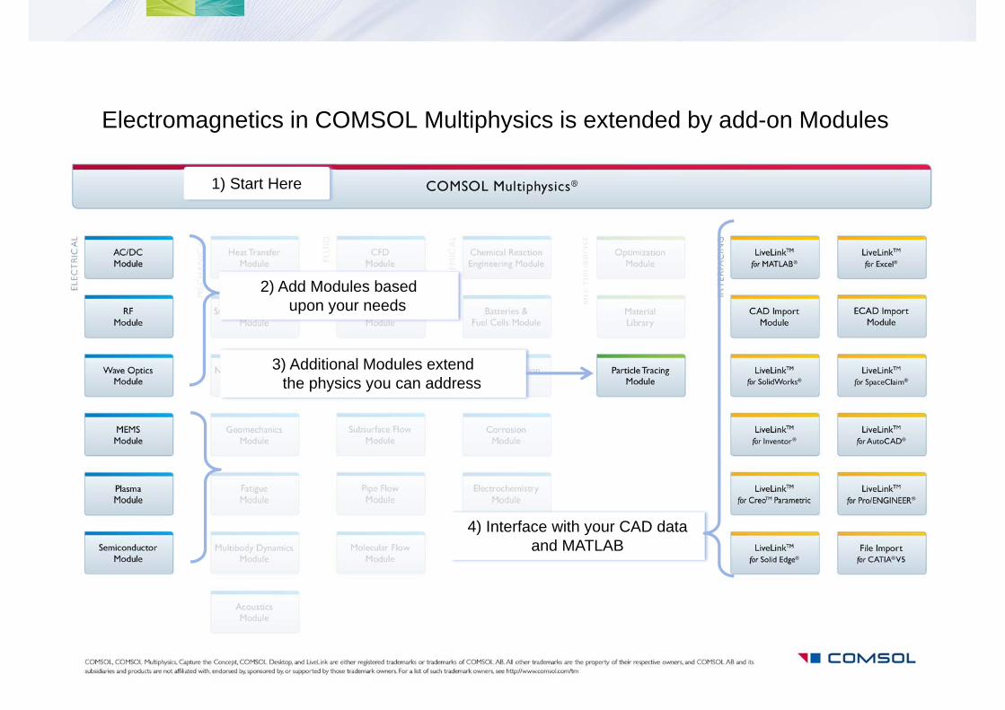
Electromagnetics in COMSOL Multiphysics is extended by add-on Modules
1) Start Here
2) Add Modules based upon your needs
4) Interface with your CAD data and MATLAB
3) Additional Modules extendthe physics you can address
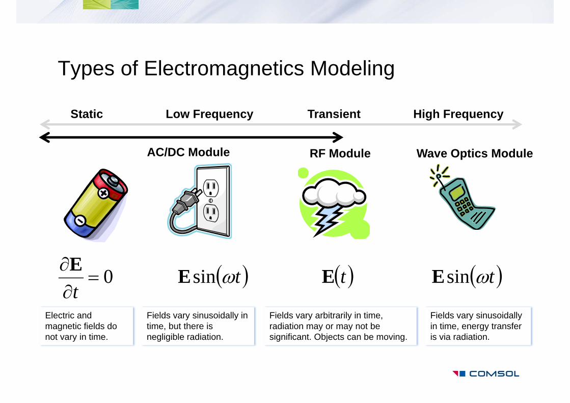
Types of Electromagnetics Modeling
RF Module
Static Low Frequency Transient High Frequency
0
tE tsinE tE tsinE
Electric and magnetic fields do not vary in time.
Fields vary sinusoidally in time, but there is negligible radiation.
Fields vary arbitrarily in time, radiation may or may not be significant. Objects can be moving.
Fields vary sinusoidallyin time, energy transfer is via radiation.
Wave Optics ModuleAC/DC Module
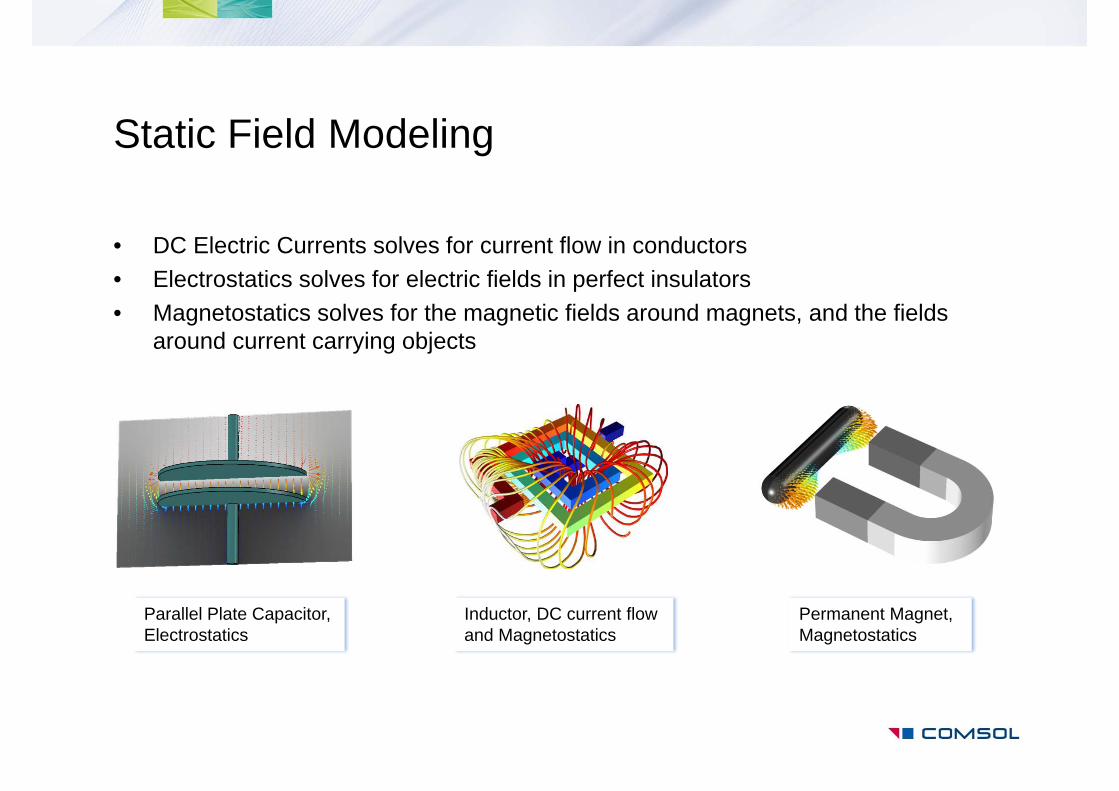
Static Field Modeling
• DC Electric Currents solves for current flow in conductors• Electrostatics solves for electric fields in perfect insulators• Magnetostatics solves for the magnetic fields around magnets, and the fields
around current carrying objects
Inductor, DC current flow and Magnetostatics
Parallel Plate Capacitor, Electrostatics
Permanent Magnet, Magnetostatics
Mutual Inductance, Magnetic Fields Analysis
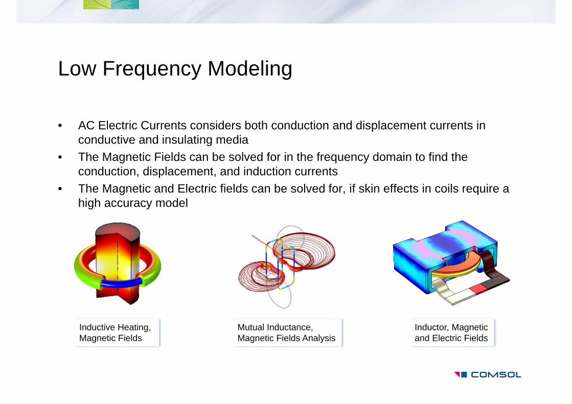
Low Frequency Modeling
• AC Electric Currents considers both conduction and displacement currents in conductive and insulating media
• The Magnetic Fields can be solved for in the frequency domain to find the conduction, displacement, and induction currents
• The Magnetic and Electric fields can be solved for, if skin effects in coils require a high accuracy model
Inductive Heating, Magnetic Fields
Inductor, Magnetic and Electric Fields
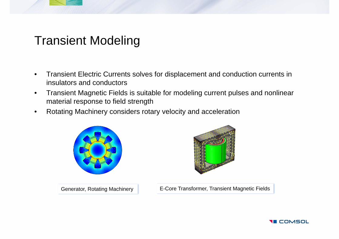
Transient Modeling
• Transient Electric Currents solves for displacement and conduction currents in insulators and conductors
• Transient Magnetic Fields is suitable for modeling current pulses and nonlinear material response to field strength
• Rotating Machinery considers rotary velocity and acceleration
E-Core Transformer, Transient Magnetic FieldsGenerator, Rotating Machinery
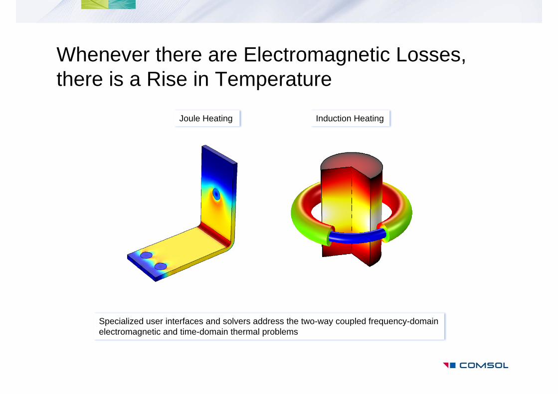
Whenever there are Electromagnetic Losses, there is a Rise in Temperature
Joule Heating Induction Heating
Specialized user interfaces and solvers address the two-way coupled frequency-domain electromagnetic and time-domain thermal problems
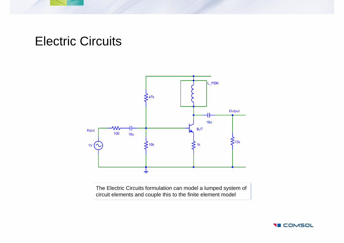
Electric Circuits
The Electric Circuits formulation can model a lumped system of circuit elements and couple this to the finite element model
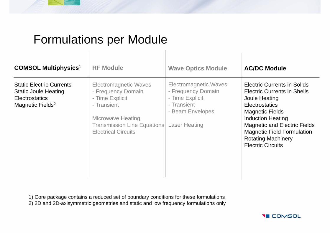
Formulations per Module
COMSOL Multiphysics1 AC/DC Module RF Module
Static Electric CurrentsStatic Joule HeatingElectrostaticsMagnetic Fields2
Electric Currents in SolidsElectric Currents in ShellsJoule HeatingElectrostaticsMagnetic FieldsInduction HeatingMagnetic and Electric FieldsMagnetic Field FormulationRotating MachineryElectric Circuits
Electromagnetic Waves- Frequency Domain- Time Explicit- Transient
Microwave HeatingTransmission Line EquationsElectrical Circuits
1) Core package contains a reduced set of boundary conditions for these formulations 2) 2D and 2D-axisymmetric geometries and static and low frequency formulations only
Wave Optics Module
Electromagnetic Waves- Frequency Domain- Time Explicit- Transient- Beam Envelopes
Laser Heating
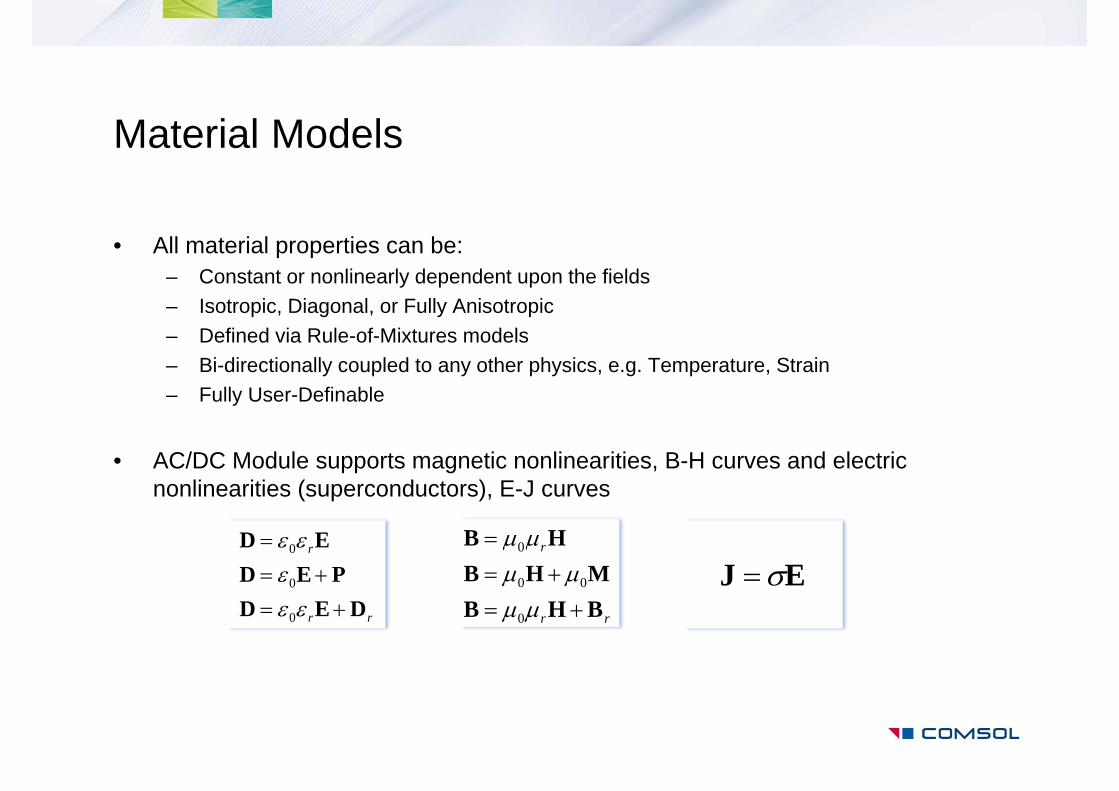
Material Models
• All material properties can be:– Constant or nonlinearly dependent upon the fields– Isotropic, Diagonal, or Fully Anisotropic– Defined via Rule-of-Mixtures models– Bi-directionally coupled to any other physics, e.g. Temperature, Strain– Fully User-Definable
• AC/DC Module supports magnetic nonlinearities, B-H curves and electric nonlinearities (superconductors), E-J curves
rr
r
DEDPED
ED
0
0
0
rr
r
BHBMHB
HB
0
00
0
EJ
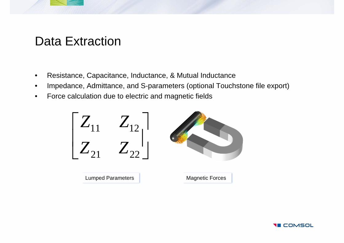
Data Extraction
• Resistance, Capacitance, Inductance, & Mutual Inductance• Impedance, Admittance, and S-parameters (optional Touchstone file export)• Force calculation due to electric and magnetic fields
Magnetic Forces
2221
1211
ZZZZ
Lumped Parameters
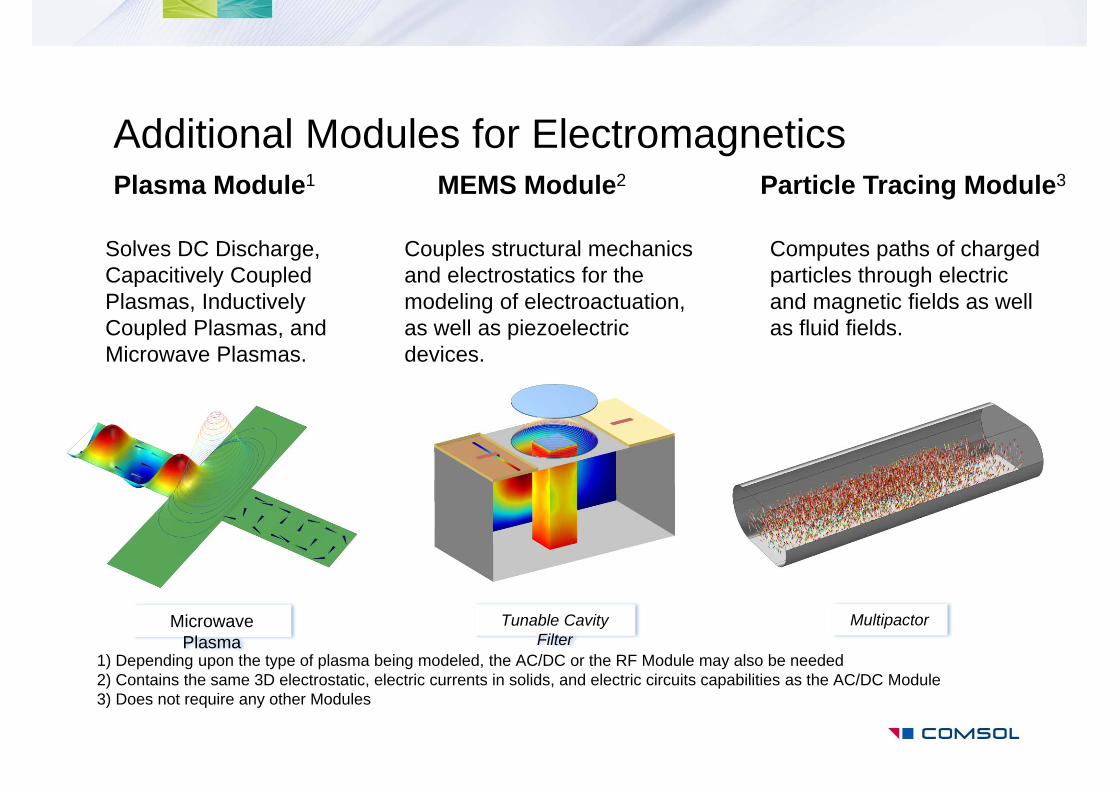
Additional Modules for ElectromagneticsPlasma Module1 MEMS Module2 Particle Tracing Module3
Tunable Cavity Filter
Microwave Plasma
Multipactor
Solves DC Discharge, Capacitively Coupled Plasmas, Inductively Coupled Plasmas, and Microwave Plasmas.
Couples structural mechanics and electrostatics for the modeling of electroactuation, as well as piezoelectric devices.
Computes paths of charged particles through electric and magnetic fields as well as fluid fields.
1) Depending upon the type of plasma being modeled, the AC/DC or the RF Module may also be needed2) Contains the same 3D electrostatic, electric currents in solids, and electric circuits capabilities as the AC/DC Module3) Does not require any other Modules
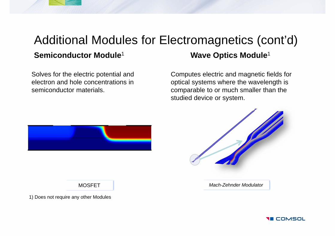
Additional Modules for Electromagnetics (cont’d)Semiconductor Module1 Wave Optics Module1
MOSFET Mach-Zehnder Modulator
Solves for the electric potential and electron and hole concentrations in semiconductor materials.
1) Does not require any other Modules
Computes electric and magnetic fields for optical systems where the wavelength is comparable to or much smaller than the studied device or system.
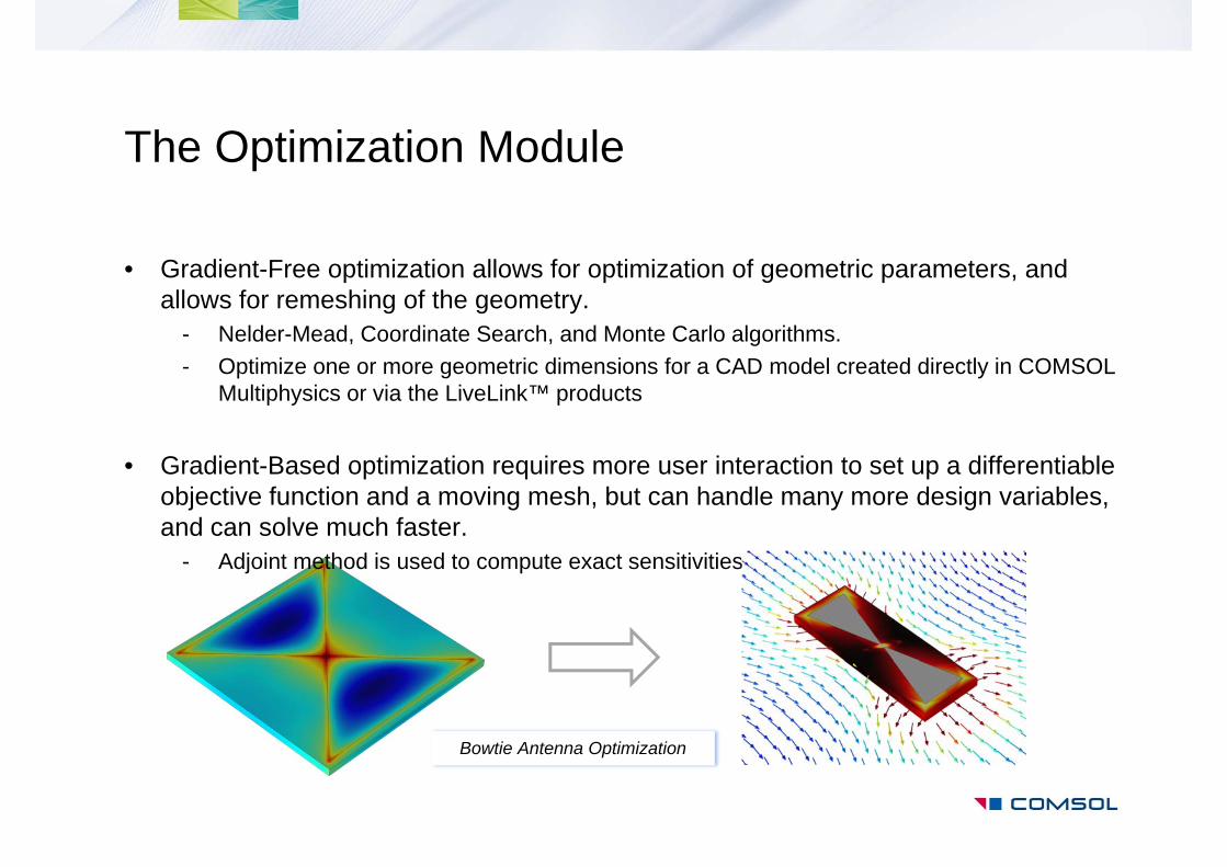
The Optimization Module
• Gradient-Free optimization allows for optimization of geometric parameters, and allows for remeshing of the geometry.
- Nelder-Mead, Coordinate Search, and Monte Carlo algorithms.- Optimize one or more geometric dimensions for a CAD model created directly in COMSOL
Multiphysics or via the LiveLink™ products
• Gradient-Based optimization requires more user interaction to set up a differentiable objective function and a moving mesh, but can handle many more design variables, and can solve much faster.
- Adjoint method is used to compute exact sensitivities
Bowtie Antenna Optimization
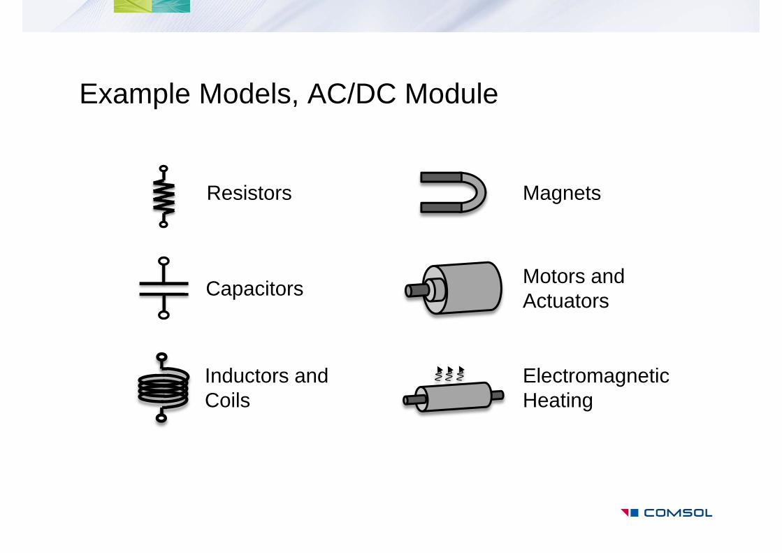
Resistors
Capacitors
Inductors and Coils
Magnets
Motors and Actuators
Electromagnetic Heating
Example Models, AC/DC Module
Resistor and Capacitor Modeling
• DC Resistive device analysis assumes that all materials are conductors, and solves the equation:
• Electrostatic analysis assumes all materials are insulators, thus:
• AC resistive and AC capacitive devices are both solved in the frequency domain using the same governing equation:
• Transient analysis also uses the same governing equation:
0 V
00 Vr
00 Vj r
00
Vt
V r

Electrostatic, Transient, and Frequency Domain modeling of a Parallel Plate Capacitor
• A parallel plate capacitor is modeled under electrostatic, frequency domain, and transient conditions
• Fringing fields and domain size effects on capacitance are studied
• Frequency domain modeling resolves the losses in dielectric materials
• Transient modeling of the charging behavior agrees with analytic solution
http://www.comsol.com/showroom/gallery/12695/
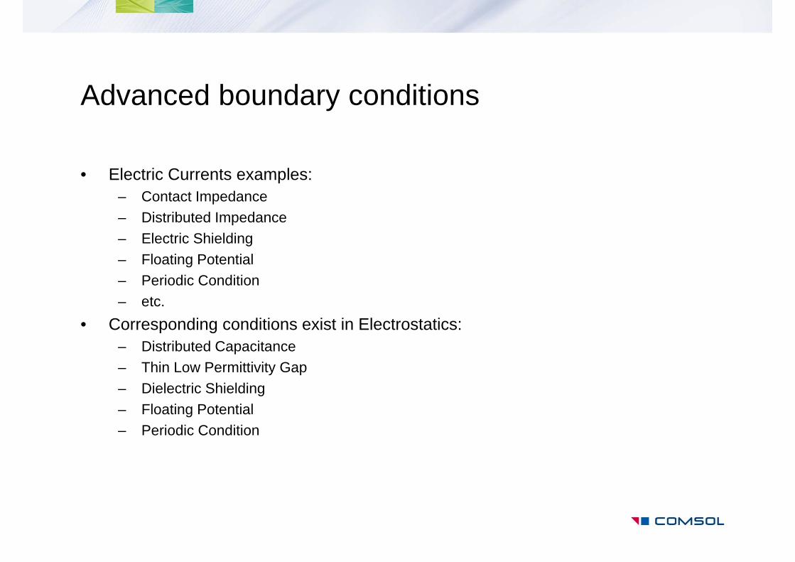
Advanced boundary conditions
• Electric Currents examples:– Contact Impedance– Distributed Impedance– Electric Shielding– Floating Potential– Periodic Condition– etc.
• Corresponding conditions exist in Electrostatics:– Distributed Capacitance– Thin Low Permittivity Gap– Dielectric Shielding– Floating Potential– Periodic Condition
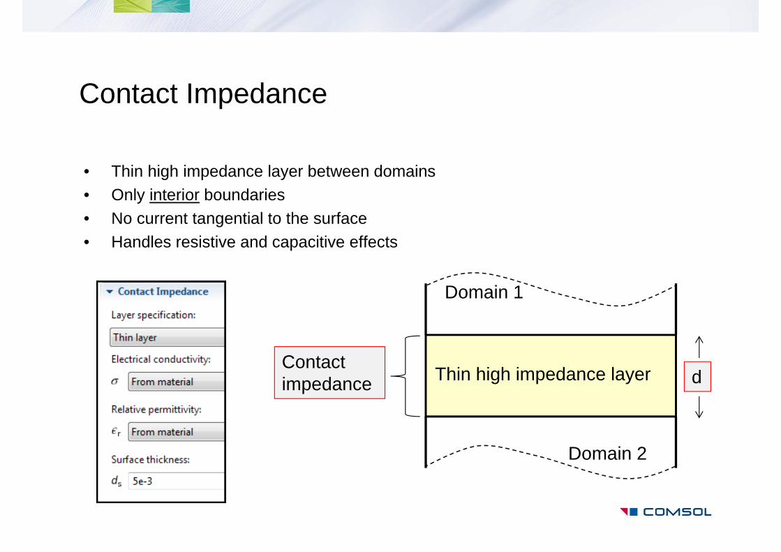
• Thin high impedance layer between domains• Only interior boundaries• No current tangential to the surface• Handles resistive and capacitive effects
Domain 1
Thin high impedance layerContact impedance d
Domain 2
Contact Impedance
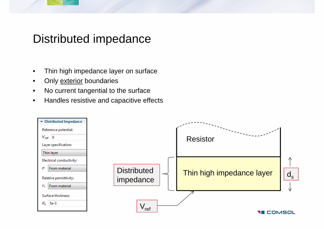
Distributed impedance
• Thin high impedance layer on surface• Only exterior boundaries• No current tangential to the surface• Handles resistive and capacitive effects
Resistor
Thin high impedance layerDistributed impedance
Vref
ds
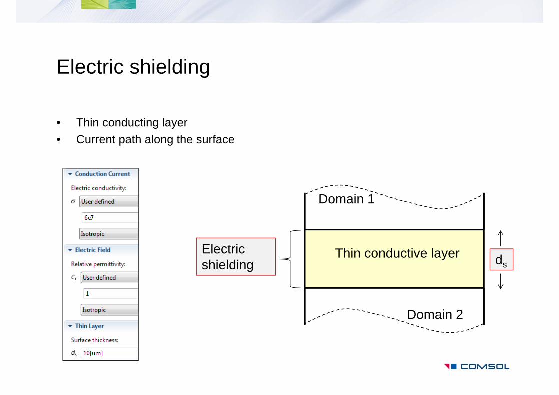
Electric shielding
• Thin conducting layer• Current path along the surface
Domain 1
Thin conductive layerElectric shielding ds
Domain 2
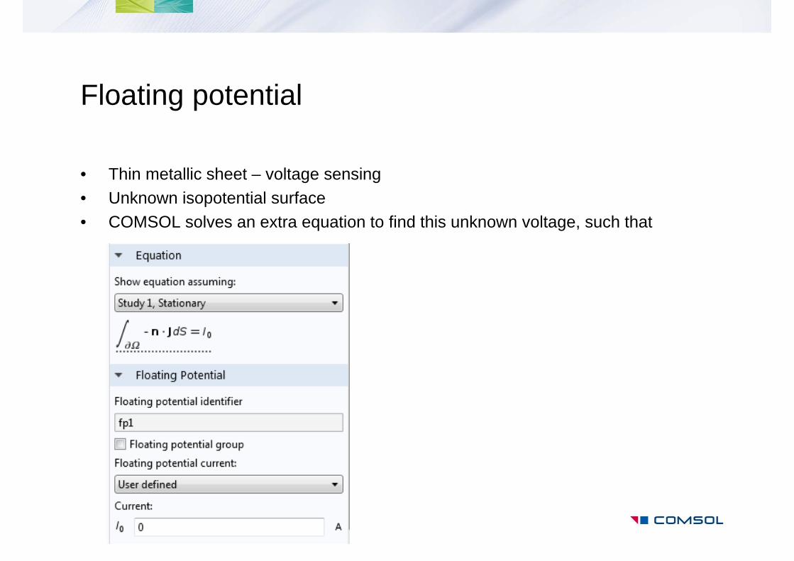
Floating potential
• Thin metallic sheet – voltage sensing• Unknown isopotential surface• COMSOL solves an extra equation to find this unknown voltage, such that
Inductor and Coil Modeling
BHABJH
1
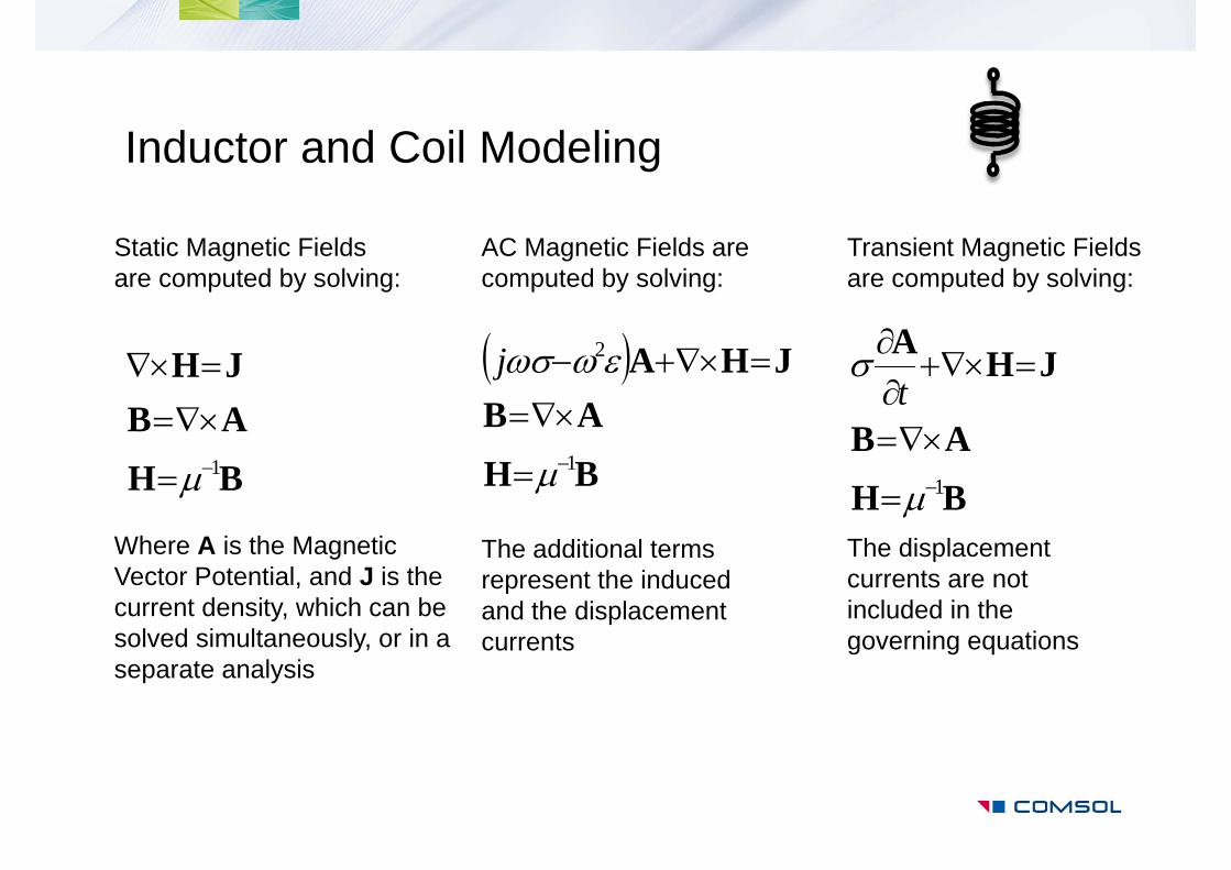
Static Magnetic Fields are computed by solving:
Where A is the Magnetic Vector Potential, and J is the current density, which can be solved simultaneously, or in a separate analysis
BHAB
JHA
1
2
j
AC Magnetic Fields are computed by solving:
The additional terms represent the induced and the displacement currents
BHAB
JHA
1
t
The displacement currents are not included in the governing equations
Transient Magnetic Fields are computed by solving:
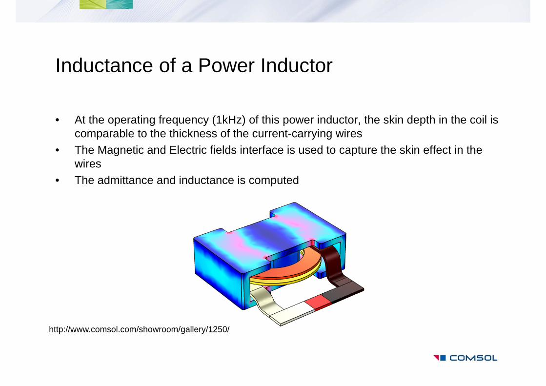
Inductance of a Power Inductor
• At the operating frequency (1kHz) of this power inductor, the skin depth in the coil is comparable to the thickness of the current-carrying wires
• The Magnetic and Electric fields interface is used to capture the skin effect in the wires
• The admittance and inductance is computed
http://www.comsol.com/showroom/gallery/1250/
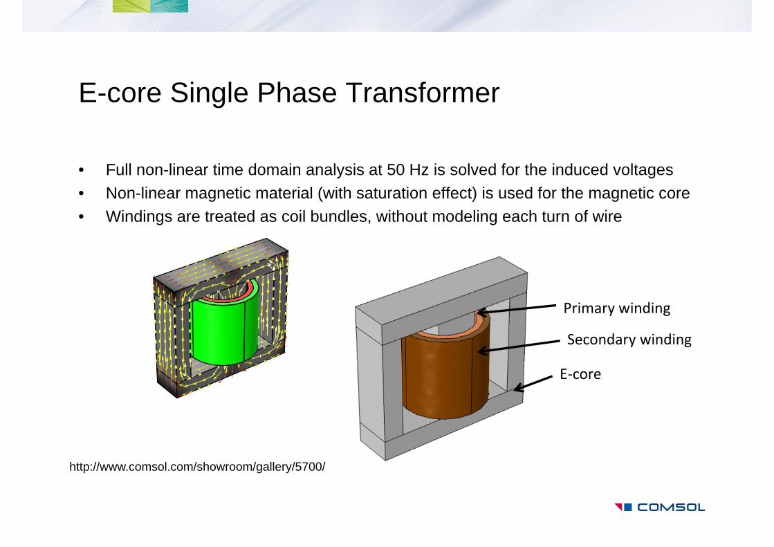
E-core Single Phase Transformer
E‐core
Primary winding
Secondary winding
http://www.comsol.com/showroom/gallery/5700/
• Full non-linear time domain analysis at 50 Hz is solved for the induced voltages• Non-linear magnetic material (with saturation effect) is used for the magnetic core• Windings are treated as coil bundles, without modeling each turn of wire
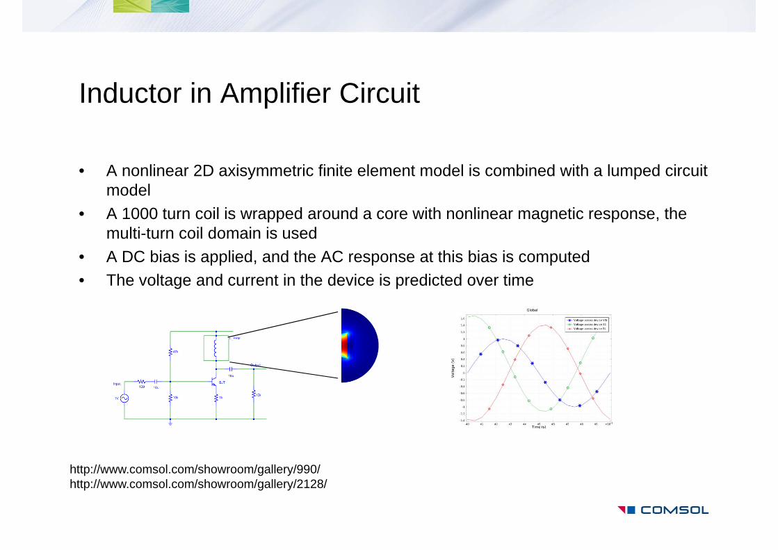
Inductor in Amplifier Circuit
• A nonlinear 2D axisymmetric finite element model is combined with a lumped circuit model
• A 1000 turn coil is wrapped around a core with nonlinear magnetic response, the multi-turn coil domain is used
• A DC bias is applied, and the AC response at this bias is computed• The voltage and current in the device is predicted over time
http://www.comsol.com/showroom/gallery/990/http://www.comsol.com/showroom/gallery/2128/
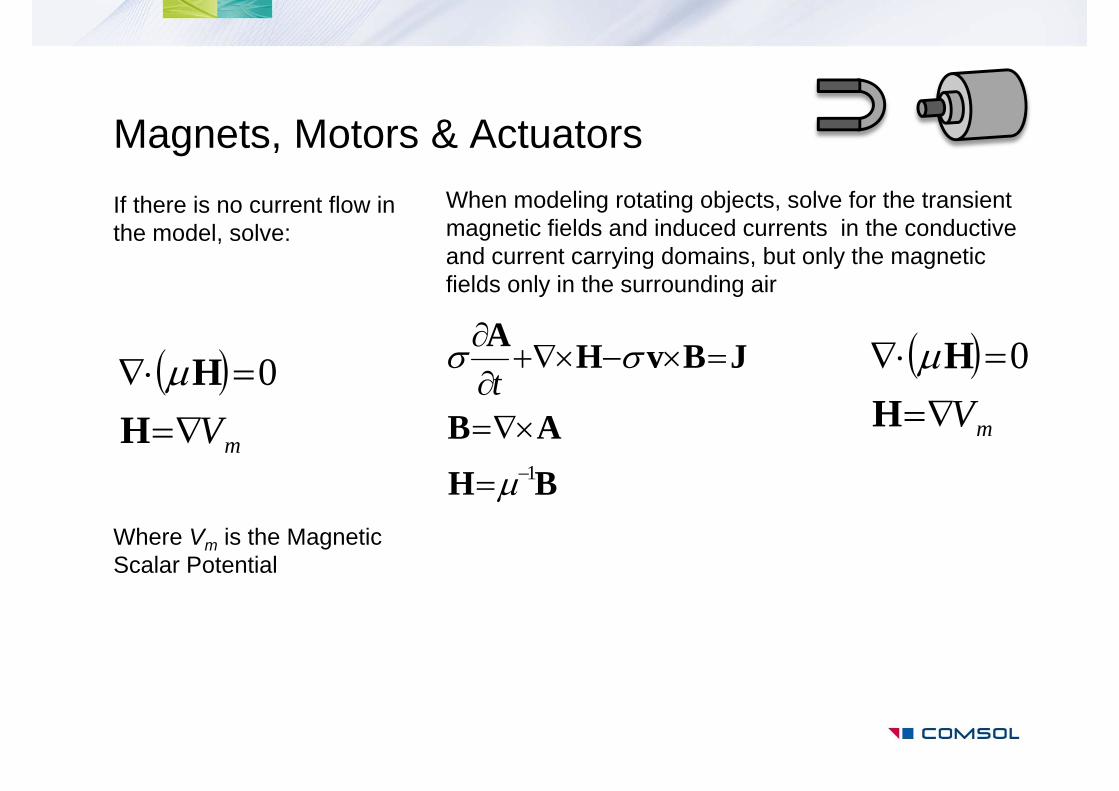
If there is no current flow in the model, solve:
Where Vm is the Magnetic Scalar Potential
Magnets, Motors & Actuators
mV
HH 0
When modeling rotating objects, solve for the transient magnetic fields and induced currents in the conductive and current carrying domains, but only the magnetic fields only in the surrounding air
mV
HH 0
BHAB
JBvHA
1
t
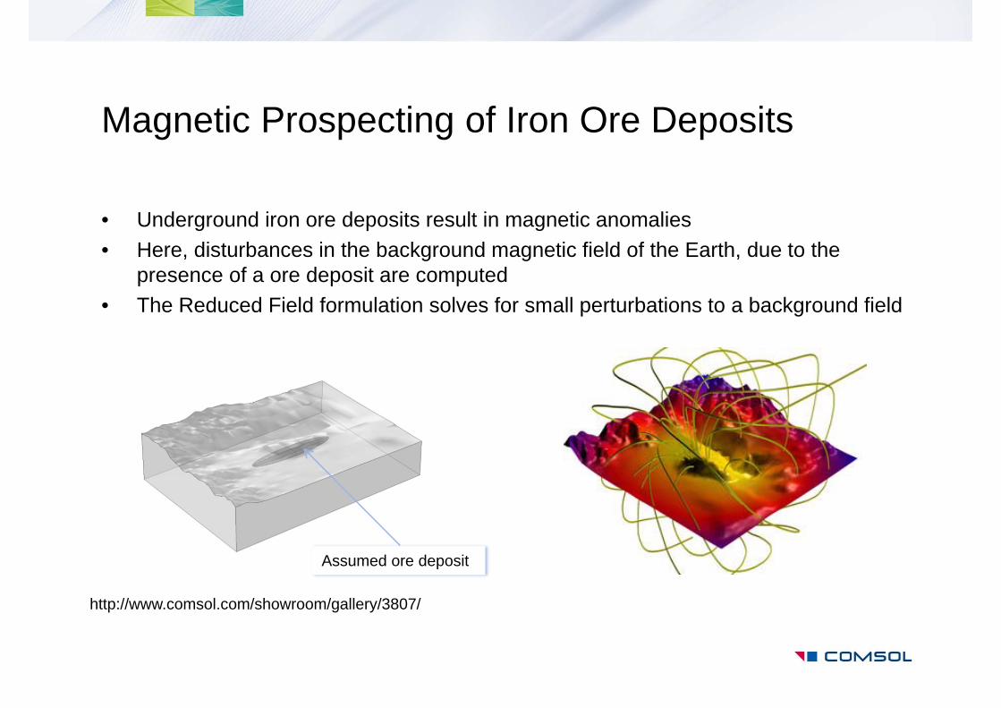
Magnetic Prospecting of Iron Ore Deposits
• Underground iron ore deposits result in magnetic anomalies• Here, disturbances in the background magnetic field of the Earth, due to the
presence of a ore deposit are computed• The Reduced Field formulation solves for small perturbations to a background field
http://www.comsol.com/showroom/gallery/3807/
Assumed ore deposit
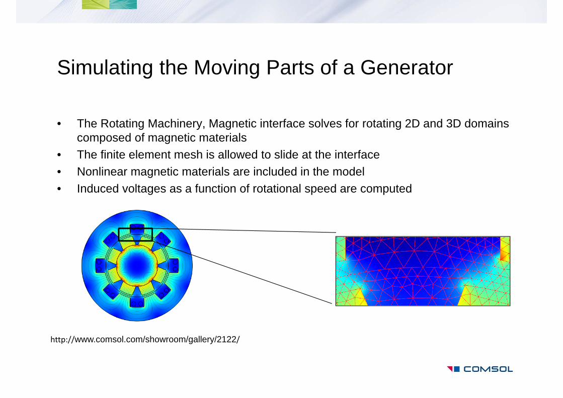
Simulating the Moving Parts of a Generator
• The Rotating Machinery, Magnetic interface solves for rotating 2D and 3D domains composed of magnetic materials
• The finite element mesh is allowed to slide at the interface• Nonlinear magnetic materials are included in the model• Induced voltages as a function of rotational speed are computed
http://www.comsol.com/showroom/gallery/2122/
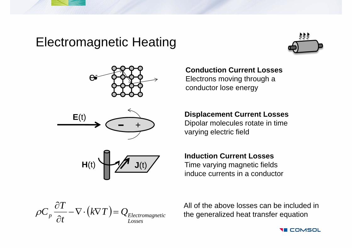
Electromagnetic Heating
Displacement Current LossesDipolar molecules rotate in time varying electric field
e-Conduction Current LossesElectrons moving through a conductor lose energy
Induction Current LossesTime varying magnetic fields induce currents in a conductor
J(t)H(t)
All of the above losses can be included in the generalized heat transfer equation
LossesneticElectromagp QTk
tTC
+E(t)
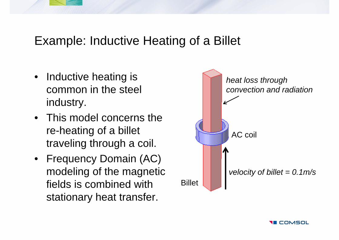
Example: Inductive Heating of a Billet
• Inductive heating is common in the steel industry.
• This model concerns the re-heating of a billet traveling through a coil.
• Frequency Domain (AC) modeling of the magnetic fields is combined with stationary heat transfer.
AC coil
velocity of billet = 0.1m/sBillet
heat loss throughconvection and radiation
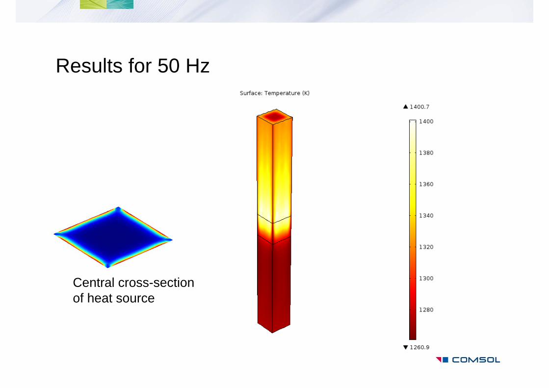
Results for 50 Hz
Central cross-section of heat source
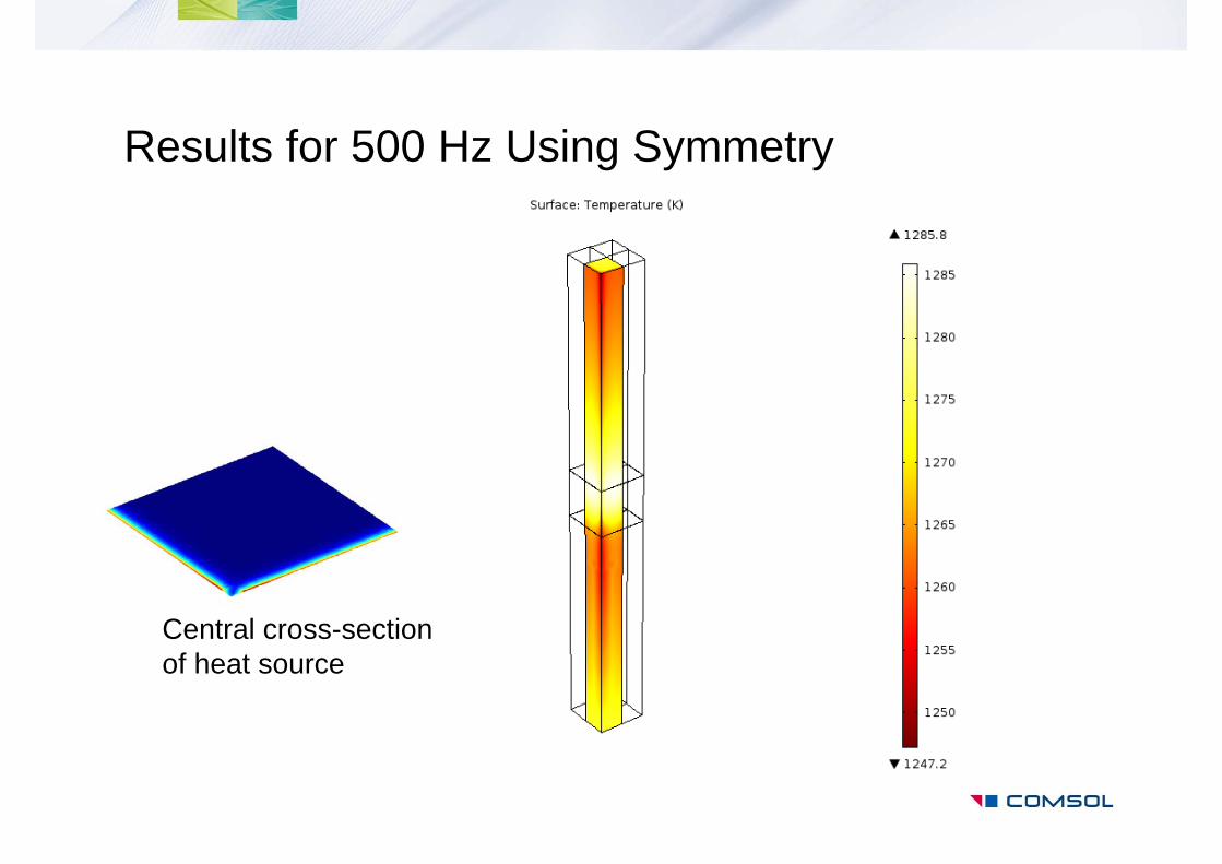
Results for 500 Hz Using Symmetry
Central cross-section of heat source