ace climatic wind tunnel · ace climatic wind tunnel ... climatic wind tunnel – ace has one of...
TRANSCRIPT
University of Ontario 2000 Simcoe Street North PH 905.721.8668
Institute of Technology Oshawa, ON, Canada L1H 7K4 www.ace.uoit.ca
ACE Climatic Wind Tunnel
Facility Fact Sheets
University of Ontario 2000 Simcoe Street North PH 905.721.8668
Institute of Technology Oshawa, ON, Canada L1H 7K4 www.ace.uoit.ca
What is ACE?
The Automotive Centre of Excellence (ACE) is the first testing and research centre of its kind in Canada, and in many respects the world. It is wholly owned and operated by the University of Ontario Institute of Technology (UOIT) and is located on the north campus in Oshawa, Ontario.
ACE is a truly independent test facility that is commercially available to customers who are seeking to bring their ideas into a proof of concept and ready for market. This is where the next generation of electric and alternative fuel vehicles, green energy technology and products we haven’t even thought of yet will be discovered, tested and validated.
ACE is a multi-purpose centre with an area of approximately 16,300 square metres. It is divided into two distinct sections: a core research facility and an integrated research and training facility. The total cost of the facility is approximately $100 million.
ACE was developed in partnership with UOIT, General Motors of Canada, the Government of Ontario, the Government of Canada and the Partners for the Advancement of Collaborative Engineering Education (PACE).
What is the core research facility? The core research facility is a heavy lab area with five distinctive test chambers:
Climatic Wind Tunnel – ACE has one of the largest and most sophisticated climatic wind tunnels in the world. In this test chamber, wind speeds can exceed 240 kilometres per hour, temperatures range from -40 to +60°C and relative humidity ranges from 5 to 95 per cent. The climatic wind tunnel has a unique variable nozzle that can optimize the airflow from 7 to 13 metres squared allowing for an unprecedented range of vehicle and other test property sizes. Coupled with this feature is a large chassis dynamometer that is integrated into an 11.5-metre turntable. Now, for the first time anywhere, vehicles and test properties can be turned into the airstream under full operating conditions to facilitate vehicle performance testing in a crosswind development. The large open chamber has a readily reconfigurable solar array that will replicate the effects of the sun and is hydrogen-capable, allowing for alternative fuels and fuel cell development.
Climate Chambers – ACE has a large and a small climate chamber that provide exacting conditions of both temperature and humidity. The large climate chamber is a high feature chamber that includes an input dynamometer coupled with a solar array. Temperatures range from -40°C to +60°C and relative humidity from 5 to 95 per cent.
University of Ontario 2000 Simcoe Street North PH 905.721.8668
Institute of Technology Oshawa, ON, Canada L1H 7K4 www.ace.uoit.ca
Climatic Four-Poster Shaker – ACE has a drive-on four-poster shaker within a climatic chamber. This vertical axis shaker can provide the motion for simulated drive surfaces to validate suspension and body durability for applications like squeak and rattle. In addition, the four-poster is capable of providing highly accelerated motion further enhancing its capabilities to support advanced structural durability and life cycle testing. Temperatures range from -40°C to +60°C and relative humidity from 5 to 95 per cent.
Multi-Axis Shaker Table (MAST) – ACE has a multi-axis shaker table or MAST in a hemi-anechoic chamber. The six axis inverted hexapod design allows for products to be tested for structural durability and the detection of noise and vibration in three dimensions.
Secure Preparation Garages – ACE has three secure preparation garages, with exhaust extraction system, tool chest, work bench and electric power
What is the Integrated Research and Training Facility? The integrated research and training facility spans five floors with space dedicated for research, education and training. It has offices, laboratories, conference rooms and common work areas that are available to rent. This facility will foster an environment for collaboration and interaction between industry, researchers and students. What are the potential markets? In addition to conventional automotive applications, ACE is suitable for testing alternative fuel, hybrid and electric vehicles. It is large enough to accommodate trucks, tandem drive systems, full coach buses, light rail transit, aerospace, military and agricultural applications, wind turbines and solar panels. Furthermore, ACE could be used to train military personnel, rescue crews or competitive athletes, to carry out performance testing of outdoor survival gear. It has the potential to assist the movie industry or test products that are subject to severe wind, humidity, snow, icing or desert heat. Booking ACE ACE is available to rent by those with a need for its unique capabilities, including: manufacturers of all descriptions, start-up companies and researchers in Canada and from around the world. Clients can rent the entire facility or specific chambers at an hourly rate that is globally competitive. For more detailed information or to take a tour of ACE, please visit our website at: www.ace.uoit.ca.
University of Ontario 2000 Simcoe Street North PH 905.721.8668
Institute of Technology Oshawa, ON, Canada L1H 7K4 www.ace.uoit.ca
CLIMATIC WIND TUNNEL
Fact Sheet
Key Features
Adjustable nozzle 7- 13m2 and long test section to accommodate a wide range of vehicle size
and type, from small cars to Class 8 trucks and buses, with wind speeds in excess of 240kph
Temperature from -40oC to +60oC and humidity from 5% to 95% RH
Exceptional flow quality for advanced aerodynamic simulation in thermodynamic testing
Low background noise level (71dBA at 50kph) for the detection of vehicle drive-away anomalies
such as misfires, transmission hesitation, etc.
Unique independently-power rolls chassis dynamometer in a turntable to enable cross-wind
testing
Solar simulation system up to 1100W/m2 intensity with sunrise-sunset simulation capabilities
Blowing rain, falling and blowing snow simulation
Complete suite of ancillary systems for customer vehicle operation, including hydrogen and
electric vehicle compatibility
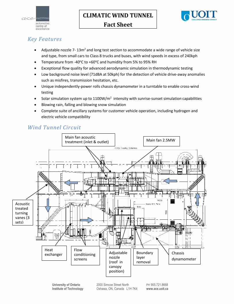
Wind Tunnel Circuit
Chassis
dynamometer
Adjustable nozzle (roof in canopy position)
Main fan 2.5MW
Acoustic treated turning vanes (3 sets)
Heat exchanger
Flow conditioning screens
Boundary layer removal
Main fan acoustic treatment (inlet & outlet)
University of Ontario 2000 Simcoe Street North PH 905.721.8668
Institute of Technology Oshawa, ON, Canada L1H 7K4 www.ace.uoit.ca
CLIMATIC WIND TUNNEL
Fact Sheet
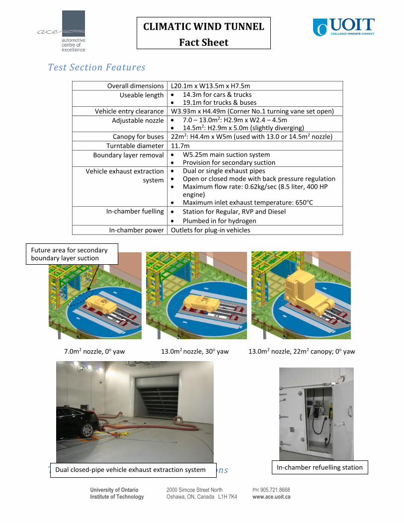
Test Section Features
Overall dimensions L20.1m x W13.5m x H7.5m
Useable length 14.3m for cars & trucks 19.1m for trucks & buses
Vehicle entry clearance W3.93m x H4.49m (Corner No.1 turning vane set open)
Adjustable nozzle 7.0 – 13.0m2: H2.9m x W2.4 – 4.5m 14.5m2: H2.9m x 5.0m (slightly diverging)
Canopy for buses 22m2: H4.4m x W5m (used with 13.0 or 14.5m2 nozzle)
Turntable diameter 11.7m
Boundary layer removal W5.25m main suction system Provision for secondary suction
Vehicle exhaust extraction system
Dual or single exhaust pipes Open or closed mode with back pressure regulation Maximum flow rate: 0.62kg/sec (8.5 liter, 400 HP
engine) Maximum inlet exhaust temperature: 650oC
In-chamber fuelling Station for Regular, RVP and Diesel
Plumbed in for hydrogen
In-chamber power Outlets for plug-in vehicles
7.0m2 nozzle, 0o yaw 13.0m2 nozzle, 30o yaw 13.0m2 nozzle, 22m2 canopy; 0o yaw
Thermal and Wind Speed Specifications
Future area for secondary boundary layer suction area
In-chamber refuelling station Dual closed-pipe vehicle exhaust extraction system
University of Ontario 2000 Simcoe Street North PH 905.721.8668
Institute of Technology Oshawa, ON, Canada L1H 7K4 www.ace.uoit.ca
CLIMATIC WIND TUNNEL
Fact Sheet
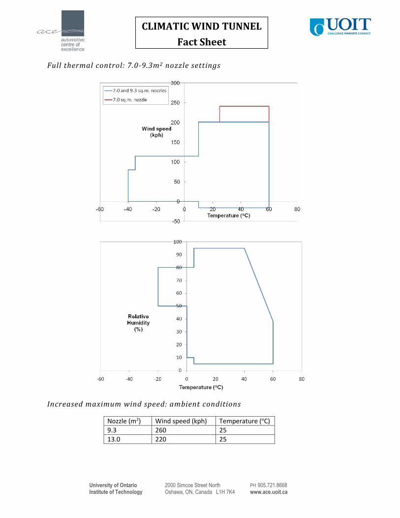
Full thermal control: 7.0-9.3m2 nozzle settings
Increased maximum wind speed: ambient conditions
Nozzle (m2) Wind speed (kph) Temperature (oC)
9.3 260 25
13.0 220 25
University of Ontario 2000 Simcoe Street North PH 905.721.8668
Institute of Technology Oshawa, ON, Canada L1H 7K4 www.ace.uoit.ca
CLIMATIC WIND TUNNEL
Fact Sheet
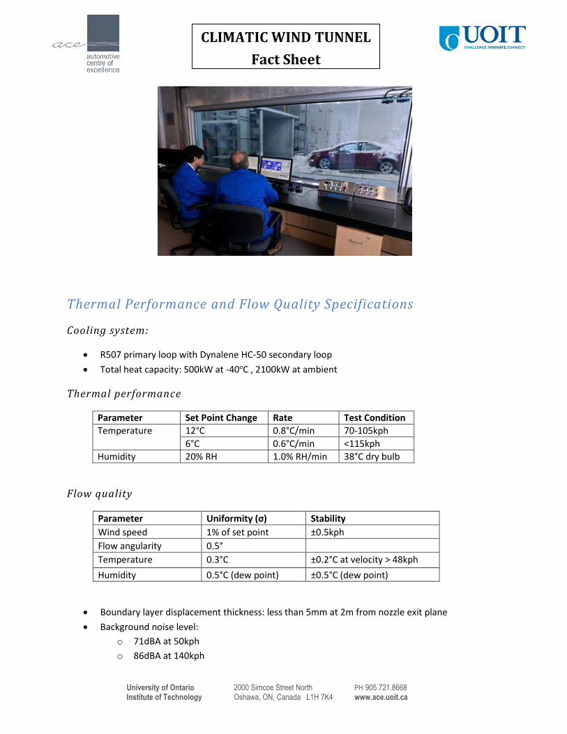
Thermal Performance and Flow Quality Specifications
Cooling system:
R507 primary loop with Dynalene HC-50 secondary loop
Total heat capacity: 500kW at -40oC , 2100kW at ambient
Thermal performance
Parameter Set Point Change Rate Test Condition
Temperature 12°C 0.8°C/min 70-105kph
6°C 0.6°C/min <115kph
Humidity 20% RH 1.0% RH/min 38°C dry bulb
Flow quality
Parameter Uniformity (σ) Stability
Wind speed 1% of set point ±0.5kph
Flow angularity 0.5°
Temperature 0.3°C ±0.2°C at velocity > 48kph
Humidity 0.5°C (dew point) ±0.5°C (dew point)
Boundary layer displacement thickness: less than 5mm at 2m from nozzle exit plane
Background noise level:
o 71dBA at 50kph
o 86dBA at 140kph
University of Ontario 2000 Simcoe Street North PH 905.721.8668
Institute of Technology Oshawa, ON, Canada L1H 7K4 www.ace.uoit.ca
CLIMATIC WIND TUNNEL
Fact Sheet
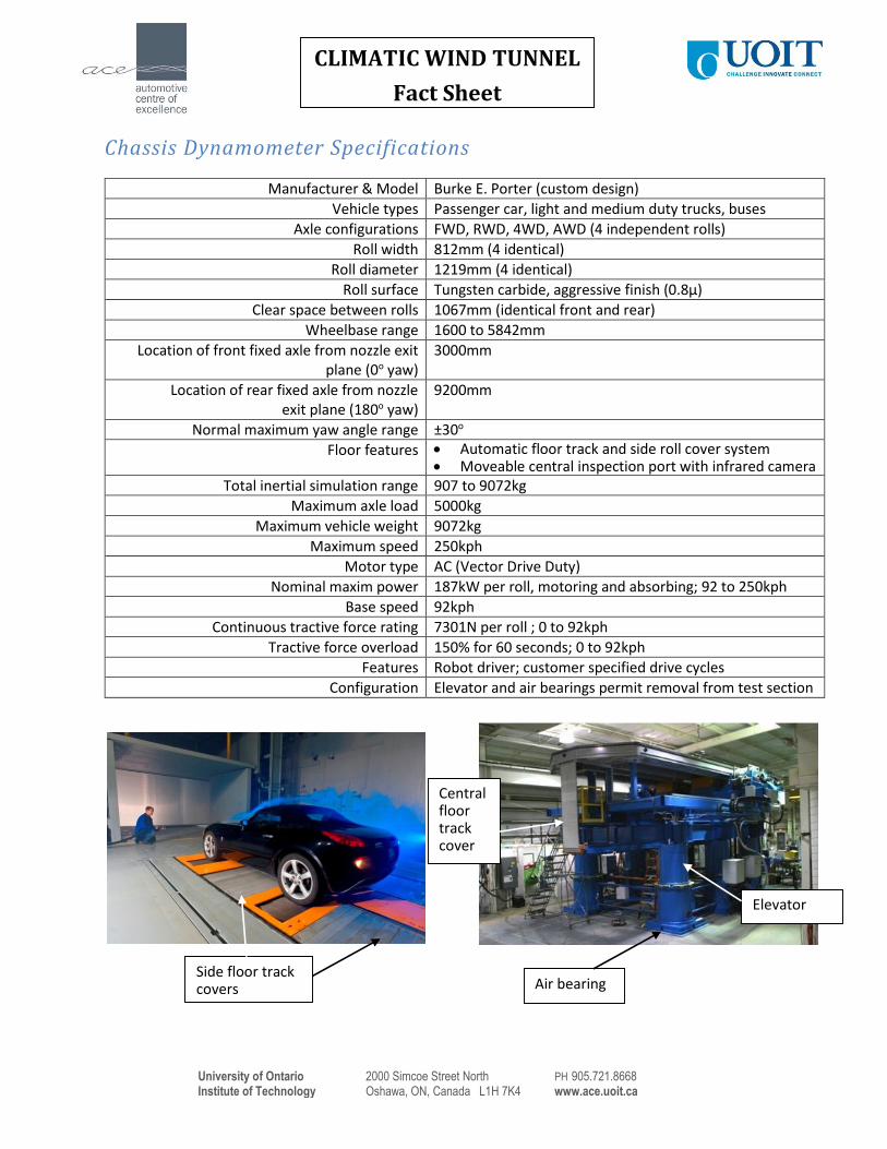
Chassis Dynamometer Specifications
Manufacturer & Model Burke E. Porter (custom design)
Vehicle types Passenger car, light and medium duty trucks, buses
Axle configurations FWD, RWD, 4WD, AWD (4 independent rolls)
Roll width 812mm (4 identical)
Roll diameter 1219mm (4 identical)
Roll surface Tungsten carbide, aggressive finish (0.8µ)
Clear space between rolls 1067mm (identical front and rear)
Wheelbase range 1600 to 5842mm
Location of front fixed axle from nozzle exit plane (0o yaw)
3000mm
Location of rear fixed axle from nozzle exit plane (180o yaw)
9200mm
Normal maximum yaw angle range ±30o
Floor features Automatic floor track and side roll cover system Moveable central inspection port with infrared camera
Total inertial simulation range 907 to 9072kg
Maximum axle load 5000kg
Maximum vehicle weight 9072kg
Maximum speed 250kph
Motor type AC (Vector Drive Duty)
Nominal maxim power 187kW per roll, motoring and absorbing; 92 to 250kph
Base speed 92kph
Continuous tractive force rating 7301N per roll ; 0 to 92kph
Tractive force overload 150% for 60 seconds; 0 to 92kph
Features Robot driver; customer specified drive cycles
Configuration Elevator and air bearings permit removal from test section
Side floor track covers Air bearing
Elevator
Central floor track cover
University of Ontario 2000 Simcoe Street North PH 905.721.8668
Institute of Technology Oshawa, ON, Canada L1H 7K4 www.ace.uoit.ca
CLIMATIC WIND TUNNEL
Fact Sheet
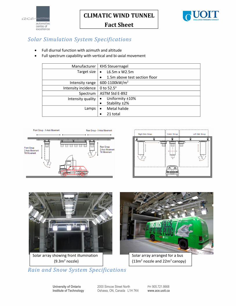
Solar Simulation System Specifications
Full diurnal function with azimuth and altitude
Full spectrum capability with vertical and bi-axial movement
Manufacturer KHS Steuernagel
Target size L6.5m x W2.5m
1.5m above test section floor
Intensity range 600-1100kW/m2
Intensity incidence 0 to 52.5o
Spectrum ASTM Std E-892
Intensity quality Uniformity ±10% Stability ±2%
Lamps Metal halide
21 total
Rain and Snow System Specifications
Solar array arranged for a bus
(13m2 nozzle and 22m2 canopy)
Solar array showing front illumination
(9.3m2 nozzle)
University of Ontario 2000 Simcoe Street North PH 905.721.8668
Institute of Technology Oshawa, ON, Canada L1H 7K4 www.ace.uoit.ca
CLIMATIC WIND TUNNEL
Fact Sheet
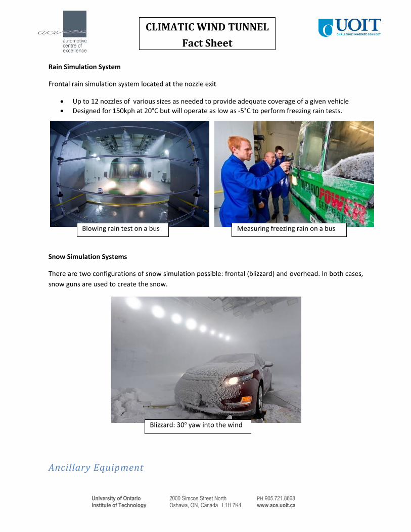
Rain Simulation System
Frontal rain simulation system located at the nozzle exit
Up to 12 nozzles of various sizes as needed to provide adequate coverage of a given vehicle
Designed for 150kph at 20°C but will operate as low as -5°C to perform freezing rain tests.
Snow Simulation Systems
There are two configurations of snow simulation possible: frontal (blizzard) and overhead. In both cases,
snow guns are used to create the snow.
Ancillary Equipment
Blizzard: 30o yaw into the wind
Blowing rain test on a bus Measuring freezing rain on a bus
University of Ontario 2000 Simcoe Street North PH 905.721.8668
Institute of Technology Oshawa, ON, Canada L1H 7K4 www.ace.uoit.ca
CLIMATIC WIND TUNNEL
Fact Sheet
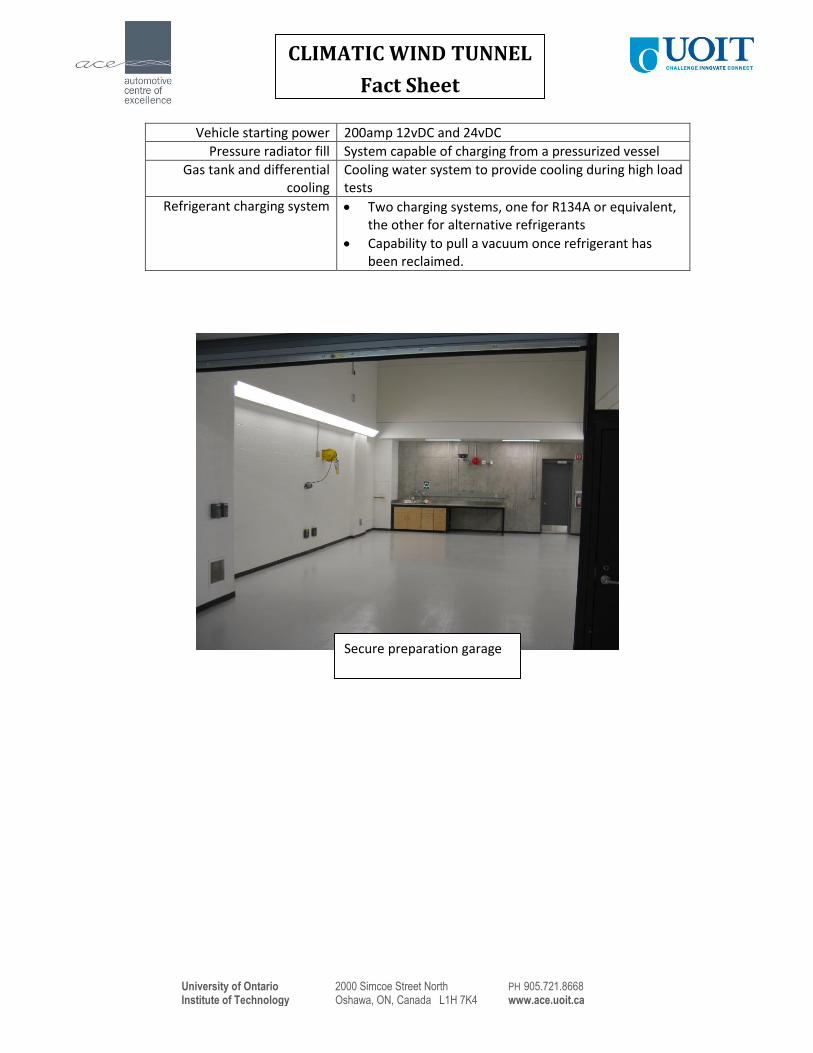
Vehicle starting power 200amp 12vDC and 24vDC
Pressure radiator fill System capable of charging from a pressurized vessel
Gas tank and differential cooling
Cooling water system to provide cooling during high load tests
Refrigerant charging system Two charging systems, one for R134A or equivalent, the other for alternative refrigerants
Capability to pull a vacuum once refrigerant has been reclaimed.
Secure preparation garage
University of Ontario 2000 Simcoe Street North PH 905.721.8668
Institute of Technology Oshawa, ON, Canada L1H 7K4 www.ace.uoit.ca
LARGE CLIMATE CHAMBER
Fact Sheet
Key Features
Exceptionally long test section to permit articulated buses
Temperature from -40oC to +60oC and humidity from 5% to 95% RH
Chassis dynamometer
Solar simulation system up to 1200W/m2 intensity
Inter-chamber door to Small Climate Chamber to permit insertion of a test bench to effect a
‘three chamber’ mode
Complete suite of ancillary systems for customer vehicle operation, including hydrogen and
electric vehicle compatibility
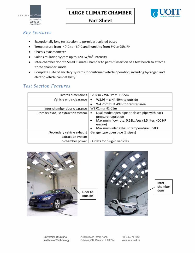
Test Section Features
Overall dimensions L20.8m x W6.0m x H5.55m
Vehicle entry clearance W3.93m x H4.49m to outside
W4.26m x H4.49m to transfer area
Inter-chamber door clearance W2.01m x H2.01m
Primary exhaust extraction system Dual mode: open pipe or closed pipe with back pressure regulation
Maximum flow rate: 0.62kg/sec (8.5 liter, 400 HP engine)
Maximum inlet exhaust temperature: 650oC Secondary vehicle exhaust
extraction system Garage type open pipe (2 pipes)
In-chamber power Outlets for plug-in vehicles
Door to outside
Inter-chamber door
University of Ontario 2000 Simcoe Street North PH 905.721.8668
Institute of Technology Oshawa, ON, Canada L1H 7K4 www.ace.uoit.ca
LARGE CLIMATE CHAMBER
Fact Sheet
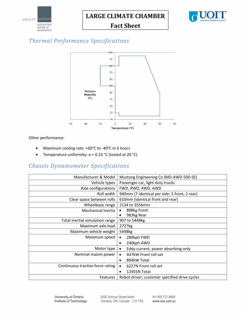
Thermal Performance Specifications
Other performance:
Maximum cooling rate: +60oC to -40oC in 6 hours
Temperature uniformity: σ = 0.33 °C (tested at 20 °C)
Chassis Dynamometer Specifications
Manufacturer & Model Mustang Engineering Co (MD-AWD-500-SE)
Vehicle types Passenger car, light duty trucks
Axle configurations FWD, RWD, 4WD, AWD
Roll width 940mm (7 identical per side: 5 front, 2 rear)
Clear space between rolls 610mm (identical front and rear)
Wheelbase range 2134 to 3556mm
Mechanical Inertia 888kg Front 983kg Rear
Total inertial simulation range 907 to 5448kg
Maximum axle load 2727kg
Maximum vehicle weight 5448kg
Maximum speed 280kph FWD
240kph AWD
Motor type Eddy current, power absorbing only
Nominal maxim power 447kW Front roll set
894kW Total
Continuous tractive force rating 6227N Front roll set
12455N Total
Features Robot driver; customer specified drive cycles
University of Ontario 2000 Simcoe Street North PH 905.721.8668
Institute of Technology Oshawa, ON, Canada L1H 7K4 www.ace.uoit.ca
LARGE CLIMATE CHAMBER
Fact Sheet
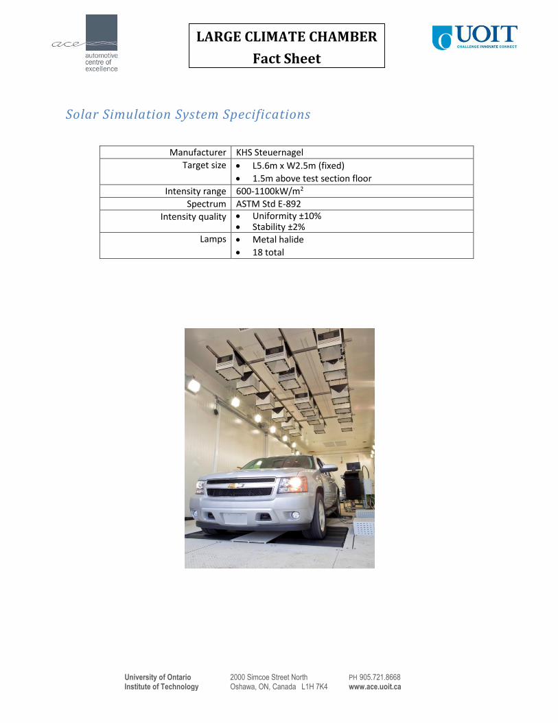
Solar Simulation System Specifications
Manufacturer KHS Steuernagel
Target size L5.6m x W2.5m (fixed)
1.5m above test section floor
Intensity range 600-1100kW/m2
Spectrum ASTM Std E-892
Intensity quality Uniformity ±10% Stability ±2%
Lamps Metal halide
18 total
University of Ontario 2000 Simcoe Street North PH 905.721.8668
Institute of Technology Oshawa, ON, Canada L1H 7K4 www.ace.uoit.ca
SMALL CLIMATE CHAMBER
Fact Sheet
Key Features
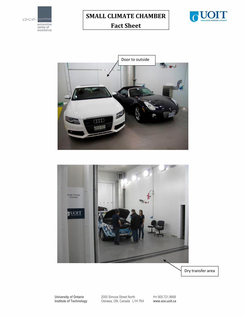
Large enough to accommodate two cars
Temperature from -40oC to +60oC and humidity from 5% to 95% RH
Inter-chamber door to Large Climate Chamber to permit insertion of a test bench to effect a
‘three chamber’ mode
Directly linked to climatic wind tunnel via dry transfer area
Complete suite of ancillary systems for customer vehicle operation, including hydrogen and
electric vehicle compatibility
Test Section Features
Overall dimensions L9.0m x W6.0m x H5.5m
Vehicle entry clearance W3.68m x H4.49m to outside
W4.26m x H4.49m to transfer area
Inter-chamber door clearance W2.01m x H2.01m
Passive exhaust extraction Garage type
In-chamber power Outlets for plug-in vehicles
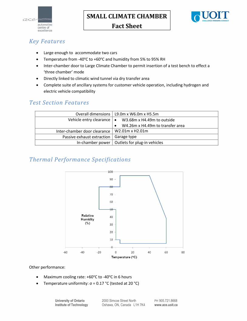
Thermal Performance Specifications
Other performance:
Maximum cooling rate: +60oC to -40oC in 6 hours
Temperature uniformity: σ = 0.17 °C (tested at 20 °C)
University of Ontario 2000 Simcoe Street North PH 905.721.8668
Institute of Technology Oshawa, ON, Canada L1H 7K4 www.ace.uoit.ca
SMALL CLIMATE CHAMBER
Fact Sheet
Door to outside
Dry transfer area
University of Ontario 2000 Simcoe Street North PH 905.721.8668
Institute of Technology Oshawa, ON, Canada L1H 7K4 www.ace.uoit.ca
4-POST CLIMATE CHAMBER
Fact Sheet
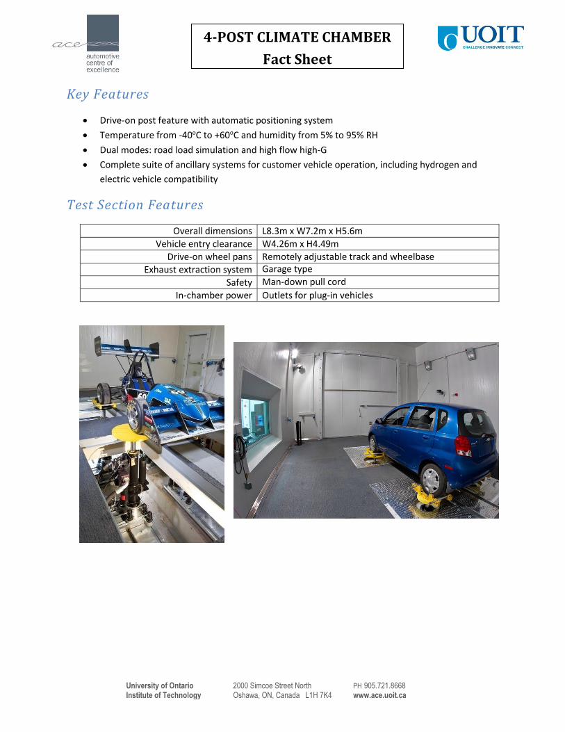
Key Features
Drive-on post feature with automatic positioning system
Temperature from -40oC to +60oC and humidity from 5% to 95% RH
Dual modes: road load simulation and high flow high-G
Complete suite of ancillary systems for customer vehicle operation, including hydrogen and
electric vehicle compatibility
Test Section Features
Overall dimensions L8.3m x W7.2m x H5.6m
Vehicle entry clearance W4.26m x H4.49m
Drive-on wheel pans Remotely adjustable track and wheelbase
Exhaust extraction system Garage type
Safety Man-down pull cord
In-chamber power Outlets for plug-in vehicles
University of Ontario 2000 Simcoe Street North PH 905.721.8668
Institute of Technology Oshawa, ON, Canada L1H 7K4 www.ace.uoit.ca
4-POST CLIMATE CHAMBER
Fact Sheet
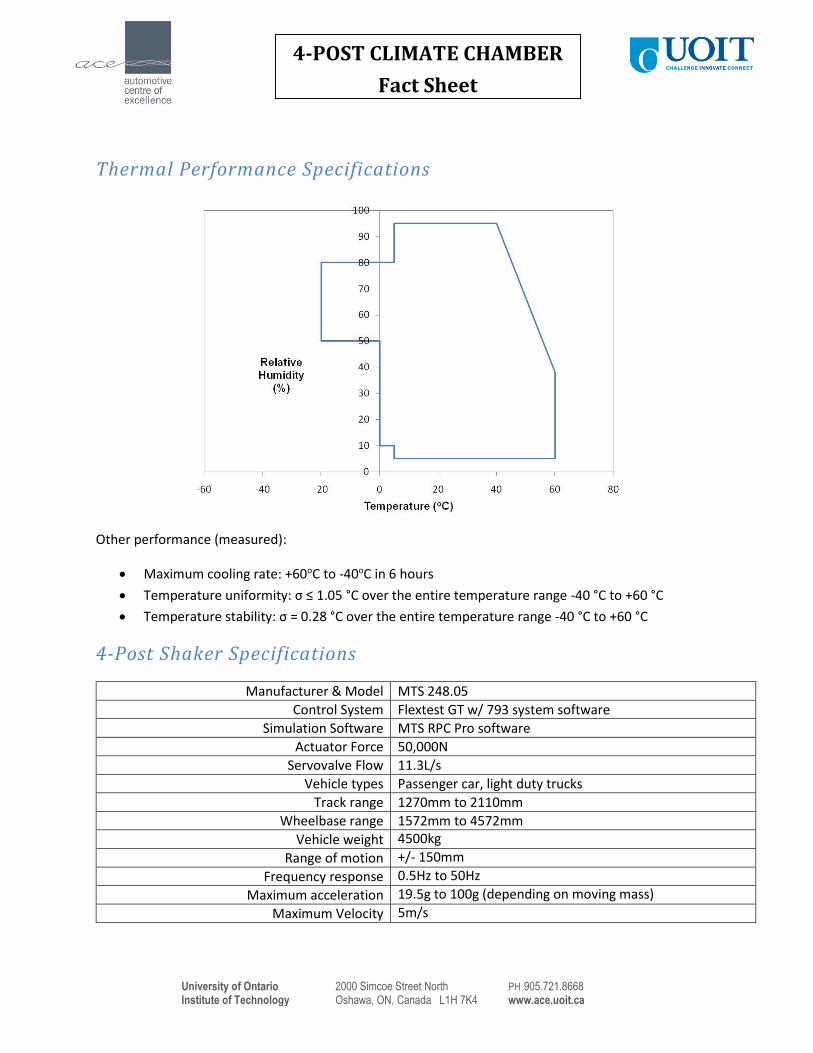
Thermal Performance Specifications
Other performance (measured):
Maximum cooling rate: +60oC to -40oC in 6 hours
Temperature uniformity: σ ≤ 1.05 °C over the entire temperature range -40 °C to +60 °C
Temperature stability: σ = 0.28 °C over the entire temperature range -40 °C to +60 °C
4-Post Shaker Specifications
Manufacturer & Model MTS 248.05
Control System Flextest GT w/ 793 system software
Simulation Software MTS RPC Pro software
Actuator Force 50,000N
Servovalve Flow 11.3L/s
Vehicle types Passenger car, light duty trucks
Track range 1270mm to 2110mm
Wheelbase range 1572mm to 4572mm
Vehicle weight 4500kg
Range of motion +/- 150mm
Frequency response 0.5Hz to 50Hz
Maximum acceleration 19.5g to 100g (depending on moving mass)
Maximum Velocity 5m/s
University of Ontario 2000 Simcoe Street North PH 905.721.8668
Institute of Technology Oshawa, ON, Canada L1H 7K4 www.ace.uoit.ca
HEMI-ANECHOIC CHAMBER
WITH MULTI-AXIS SHAKER TABLE
Fact Sheet
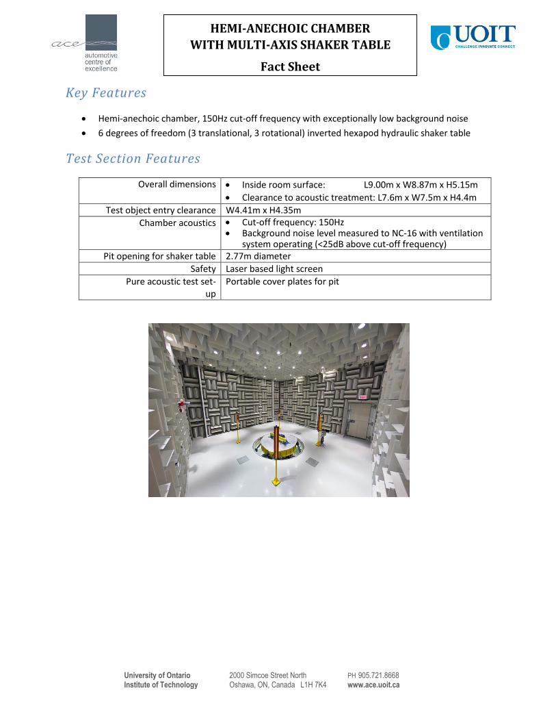
Key Features
Hemi-anechoic chamber, 150Hz cut-off frequency with exceptionally low background noise
6 degrees of freedom (3 translational, 3 rotational) inverted hexapod hydraulic shaker table
Test Section Features
Overall dimensions Inside room surface: L9.00m x W8.87m x H5.15m
Clearance to acoustic treatment: L7.6m x W7.5m x H4.4m
Test object entry clearance W4.41m x H4.35m
Chamber acoustics Cut-off frequency: 150Hz Background noise level measured to NC-16 with ventilation
system operating (<25dB above cut-off frequency) Pit opening for shaker table 2.77m diameter
Safety Laser based light screen
Pure acoustic test set-up
Portable cover plates for pit
University of Ontario 2000 Simcoe Street North PH 905.721.8668
Institute of Technology Oshawa, ON, Canada L1H 7K4 www.ace.uoit.ca
HEMI-ANECHOIC CHAMBER
WITH MULTI-AXIS SHAKER TABLE
Fact Sheet
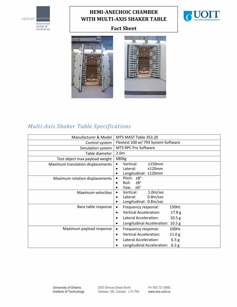
Multi-Axis Shaker Table Specifications
Manufacturer & Model MTS MAST Table 353.20
Control system Flextest 100 w/ 793 System Software
Simulation system MTS RPC Pro Software
Table diameter 2.0m
Test object max payload weight 680kg
Maximum translation displacements Vertical: ±150mm Lateral: ±120mm Longitudinal: ±120mm
Maximum rotation displacements Pitch: ±8o Roll: ±8o Yaw: ±6o
Maximum velocities Vertical: 1.0m/sec Lateral: 0.8m/sec Longitudinal: 0.8m/sec
Bare table response Frequency response: 150Hz
Vertical Acceleration: 17.8 g
Lateral Acceleration: 10.5 g
Longitudinal Acceleration: 10.5 g
Maximum payload response Frequency response: 100Hz
Vertical Acceleration: 11.0 g
Lateral Acceleration: 6.5 g
Longitudinal Acceleration: 6.5 g
University of Ontario 2000 Simcoe Street North PH 905.721.8668
Institute of Technology Oshawa, ON, Canada L1H 7K4 www.ace.uoit.ca
Key Features
Five-floor building connecting the CRF with faculty of engineering building, containing heavy lab
areas and industry-university collaborative research space
Second and third floors are university-sponsored collaborative research areas
First, fourth and fifth floors are secure areas (total area 2,190m2) containing preparation areas,
machine shop, offices, laboratories, conference rooms and common work areas that are
available to rent
Capabilities
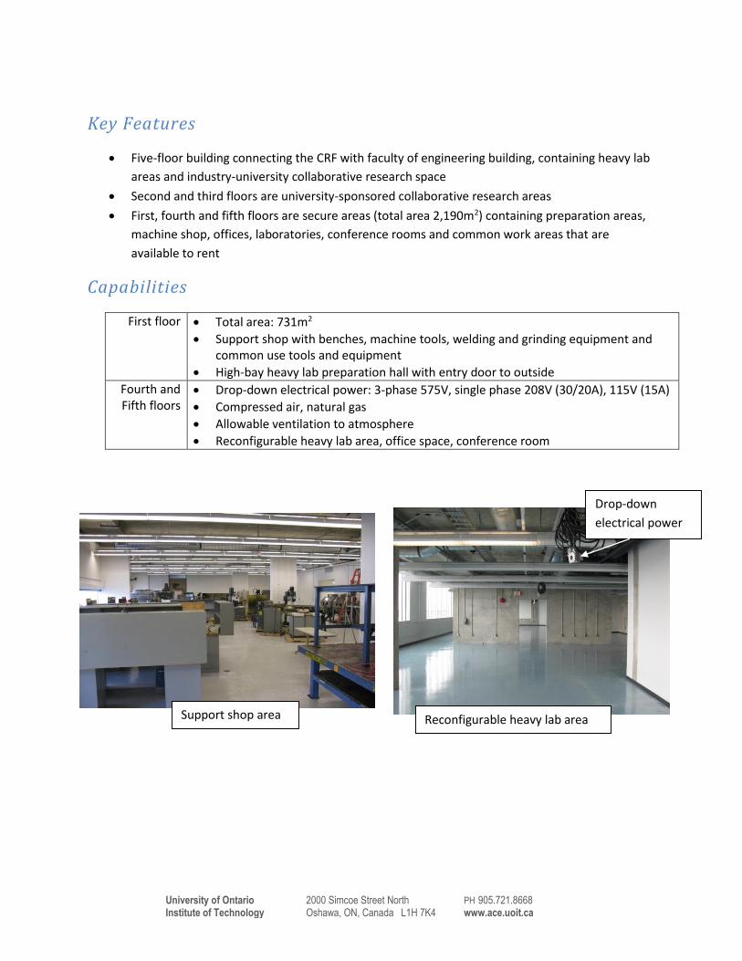
First floor Total area: 731m2
Support shop with benches, machine tools, welding and grinding equipment and common use tools and equipment
High-bay heavy lab preparation hall with entry door to outside
Fourth and Fifth floors
Drop-down electrical power: 3-phase 575V, single phase 208V (30/20A), 115V (15A)
Compressed air, natural gas
Allowable ventilation to atmosphere
Reconfigurable heavy lab area, office space, conference room
Reconfigurable heavy lab area
Drop-down
electrical power
Support shop area