acec erosion control design training 2013 - ncdot · acec erosion control design training 2013...
TRANSCRIPT

1
ACEC Erosion Control Design Training 2013
Barney Blackburn, PE, CPESC, CPSWQNCDOT – Roadside Environmental UnitSoil & Water Engineering Section Supervisor
Erosion Control Plans
►Considered Temporary Construction Plans
►PE Seal not Required or Recommended
►Level III/IIIA Certification Name & No. required on all NCDOT Erosion Control Plans
� EC Title Sheet Only

2
Reasons to Not Seal EC Plans
►Temporary, not Permanent
►Revisions would require new sealed plan sheet
►Sediment Law/Land Quality does not require
►Sediment Law is performance-based
Perimeter Devices
►Temporary Silt Fence (TSF)
►Special Sediment Control Fence (SSCF)
►Wattle Barrier (EW, CFW)
►Temporary Silt Ditch
►Earthen Berm - for this application

3
Temporary Silt Fence
Design - Utilized on Clearing & Grubbing and Final Grade Phases of Erosion Control Plans
Placement – Along stream banks and at the toe of fill slopes
Function - Silt Fence temporarily traps sheet flow from disturbed slopes allowing sediment to settle on the flow side
Silt Fence Tips
►Commonly Overused in EC design!
►Placement Locations on EC Plans:� Toe of Bridge Approach Fill Slopes
� Toe of Fill Slopes in Wetlands
� Toe of Fill Slopes in Urban Areas
� Above Culvert Inlets and Outlets, esp. on Final Grade Phase
� Perimeter of Streams and Fill Slopes inside Riparian Buffers
4
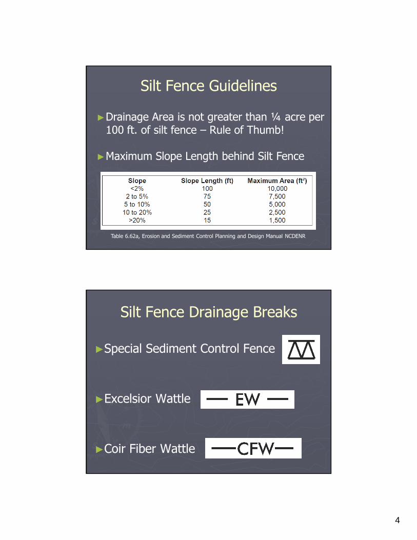
Silt Fence Guidelines
►Drainage Area is not greater than ¼ acre per 100 ft. of silt fence – Rule of Thumb!
►Maximum Slope Length behind Silt Fence
Table 6.62a, Erosion and Sediment Control Planning and Design Manual NCDENR
Silt Fence Drainage Breaks
►Special Sediment Control Fence
►Excelsior Wattle
►Coir Fiber Wattle

5
Special Sediment Control Fence
Design - Utilized on Clearing & Grubbing and Final Grade Phases of Erosion Control Plans
Placement – Short Sections between Silt Fence unless longer sections required
Function - Special Sediment Control Fence provides a drainage break for Silt Fence Sections in Low Areas
SSCF Tips
►Commonly Overused in EC design!
►Can be used in wetlands, but difficult to remove
►Placement Locations on EC Plans:
� Drainage Breaks in Silt Fence (Max. Spacing of 200 ft.)
� Adjacent to Stream Relocations
� Some Permit Conditions require Special Sediment Control Fence at Toe of Bridge Approach Fills parallel to stream

6
Silt Fence Wattle Breaks
Design - Utilized on Clearing & Grubbing and Final Grade Phases of Erosion Control Plans
Placement – Between Long Segments of Silt Fence
Function – Wattle provides a drainage break for Silt Fence Sections and in Low Areas
Wattle Break Tips
►Design for Wattle of 10 ft. in length
►Can be used in wetlands, easy to remove (or not!)
►Maximum Spacing of 200 ft.
►Use Coir Fiber Wattles (CFW) for projects > 1 year
� Environmentally Sensitive Areas (Trout, 303(d), etc.)

7
Wattle Barrier
Design - Utilized on Clearing & Grubbing and Final Grade Phases of Erosion Control Plans
Placement - At the toe of bridge approach fill slopes and along slopes
Function - Wattle Barrier temporarily traps sheet flow from disturbed slopes allowing sediment to settle on the flow side
Wattle Barrier Tips
►Utilize where Silt Fence can’t be installed
►Can be used in wetlands, easy to remove (or not!)
►Maximum Spacing of 20 ft. for breaks on slopes
►Use Coir Fiber Wattles (CFW) for projects > 1 year
� Environmentally Sensitive Areas (Trout, 303(d), etc.)

8
Wattle Barrier Update
►Utilize where vertical clearance between ground and bottom of bridge is less than 4 ft.
► Increased Minimum Diameter from 12” to 18”
►Deepened Trench from 1” to 2” to 2” to 3”
►Pay Item – Wattle Barrier, Coir Fiber Wattle Barrier
Temporary Silt Ditch
Design - Utilized on Clearing & Grubbing and Final Grade Phases of Erosion Control Plans
Placement - Toe of fill slopes
Function - TSD directs sheet flow from fill slopes into sediment traps and basins

9
TSD Tips
►Extend TSD to inflow side of sediment basins without leaving any gaps
►Place velocity checks (either a Rock Silt Check or Wattle) with TSD
►Do not place inside slope stake lines in the footprint of the project!
Earth Berm
Design - Utilized on Clearing & Grubbing and Final Grade Phases of Erosion Control Plans
Placement - Toe of fill slopes
Function – Provides sediment storage for large fill slopes where sediment basins are not feasible

10
Earth Berm Tips
►Consider for:
� Fill Slopes > 20 ft. in height measured along slope
� Fill Slopes > 2 acres in area
►Place Stone Drainage Breaks, DA < 1 acre
� Temporary Rock Silt Check Type A
� Temporary Sediment Dam Type A
►Place Geotextile Spillways, DA > 1 acre
Temporary Earth Berm Detail
2

11
Earth Berm at Toe of Fill Slope
Runoff Diversion Devices
►Temporary Diversion (TD)
►Temporary Earth Berm
►Clean Water Diversion (CWD)
►Temporary Berms and Slope Drains
12
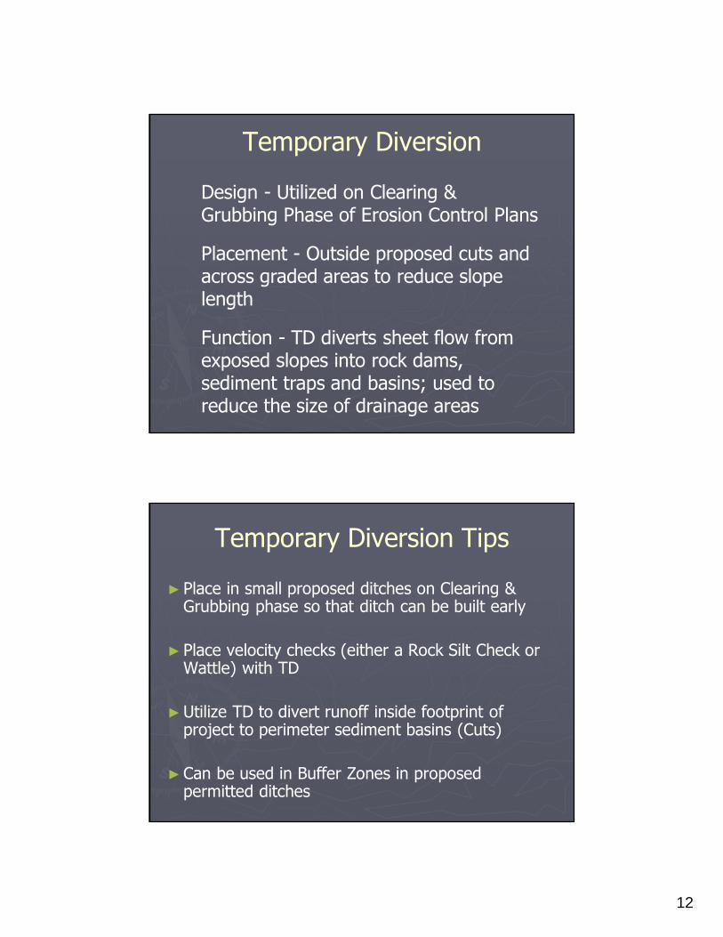
Temporary Diversion
Design - Utilized on Clearing & Grubbing Phase of Erosion Control Plans
Placement - Outside proposed cuts and across graded areas to reduce slope length
Function - TD diverts sheet flow from exposed slopes into rock dams, sediment traps and basins; used to reduce the size of drainage areas
Temporary Diversion Tips
►Place in small proposed ditches on Clearing & Grubbing phase so that ditch can be built early
►Place velocity checks (either a Rock Silt Check or Wattle) with TD
►Utilize TD to divert runoff inside footprint of project to perimeter sediment basins (Cuts)
►Can be used in Buffer Zones in proposed permitted ditches

13
Temporary Earth Berm
Design - Utilized on Clearing & Grubbing and Final Grade Phases of EC Plans
Placement - Outside cuts and fills and parallel to the ROW; across graded areas to reduce slope length (Fills)
Function - Earth Berms divert offsite runoff to minimize the runoff flowing to erosion control devices; used to reduce the size of drainage areas
Earth Berm Tips
►Include Earth Berm Detail on plan sheets where utilized
►Place velocity checks (either a Rock Silt Check or Wattle) with Earth Berms
►Place Earth Berms inside footprint of fill slopes to divert runoff to sediment basins

14
Clean Water Diversion
Design - Utilized on Clearing & Grubbing and Final Grade Phases of EC Plans
Placement - Outside cuts and fills and parallel to the ROW
Function – Clean Water Diversions divert offsite runoff to minimize the runoff flowing to erosion control devices; used to reduce the size of drainage areas
Clean Water Diversion Tips
►Include Clean Water Diversion Detail on plan sheets where utilized
►Place Type B Silt Checks for velocity control with CWD’s every 2 ft. of elevation change
►Place Type A Silt Checks at outlets
►Do not show wattles in Diversions

15
Clean Water Diversion Detail
Temporary Slope Drains
Design - Utilized on Clearing & Grubbing and Final Grade Phases of EC Plans
Placement – On large cuts and fills
Function – Convey concentrated runoff to bottom of slopes in a non-erosive manner
16
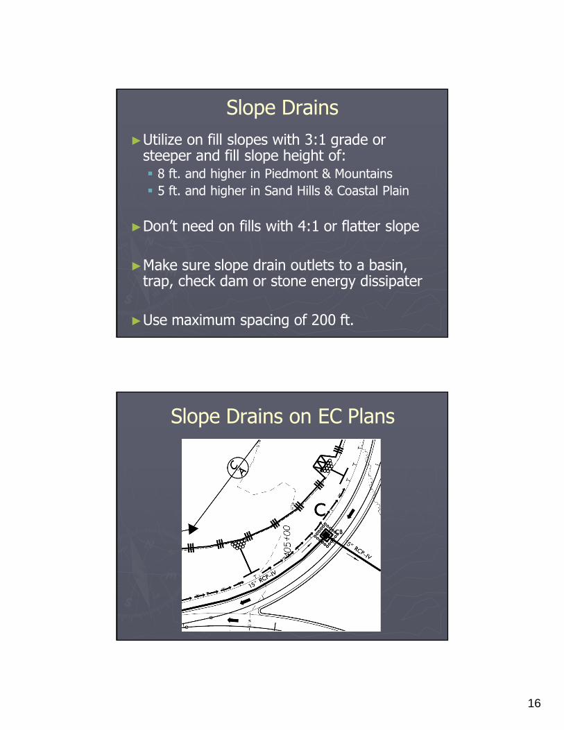
Slope Drains
►Utilize on fill slopes with 3:1 grade or steeper and fill slope height of:� 8 ft. and higher in Piedmont & Mountains
� 5 ft. and higher in Sand Hills & Coastal Plain
►Don’t need on fills with 4:1 or flatter slope
►Make sure slope drain outlets to a basin, trap, check dam or stone energy dissipater
►Use maximum spacing of 200 ft.
Slope Drains on EC Plans

17
NCG-01 Construction Permit
►Effective August 3, 2011
►Outlet devices must withdraw from basin surface unless drainage area is < 1 acre
►Ground Stabilization Time Frames of 7 or 14 days
Surface Dewatering Devices
►Skimmer Devices
►Infiltration Basins
►Silt Basin B (excavated below ground)
►Riser Basins
►Earth Berm at Toe of Fill Slopes

18
NOT Surface Dewatering Devices
►Temporary Rock Silt Checks
►Temporary Rock Sediment Dams
►Silt Fence
►Stone Inlet Protection Devices
►Wattles
Standard Sediment Basins
►Silt Basin Type B
►Temporary Rock Sediment Dam Type B
►Infiltration Basin

19
Sediment Basin FYI
►Optimal Length:Width Ratio is 3:1, with 2:1 minimum and 6:1 maximum - exceptions
►NCDOT Sediment Basins have 1.5:1 side slopes� Not Required but Flatter Side Slopes = Less Volume
►Don’t place basins in following locations:� Riparian Buffer Zones (unless permitted)
� Wetlands (unless permitted)
� Close to Homes or Businesses
� In live streams
Ideal design!
20
Silt Basin Type B
►Surface Area Requirement
� 435 ft2per cfs of Q
10 or 25peak inflow
� 325 ft2per cfs of Q
10 or 25peak inflow at drainage inlet
structures (i.e. DI’s, CB’s, etc.)
►Sediment Storage Requirement
� 3600 ft3per disturbed acre
� 1800 ft3per disturbed acre at drainage inlet structures
(i.e. DI’s, CB’s, etc.)
Silt Basin Type B Tips
►Can be utilized in medians at drainage inlets
►Utilize adjacent to Rock Pipe Inlet Sediment Traps (PIST-A, PIST-B)
� Surface Area = 435 ft2per cfs of Q
10 or 25
� Sediment Storage = 3600 ft3per disturbed acre
►Use Silt Basin B’s for additional sediment storage upgrade of drainage outlet

21
Sediment Dam Type B
►Surface Area Requirement
� 435 ft2per cfs of Q
10 or 25peak inflow
►Sediment Storage Requirement
� 3600 ft3per disturbed acre
►Minimum Weir Length is 4 ft.
►Maximum Drainage Area is 1 Acre (NCG-01)
Sediment Dam Type B Tips
►Place Temporary Rock Sediment Dams Type B (TRSD-B) at drainage outlets that do notdrain directly to a jurisdictional water body
►Place TRSD-B’s inside footprint of project on Clearing & Grubbing EC Plans
►TRSD-B’s are relatively inexpensive, but have largest basin footprint
22
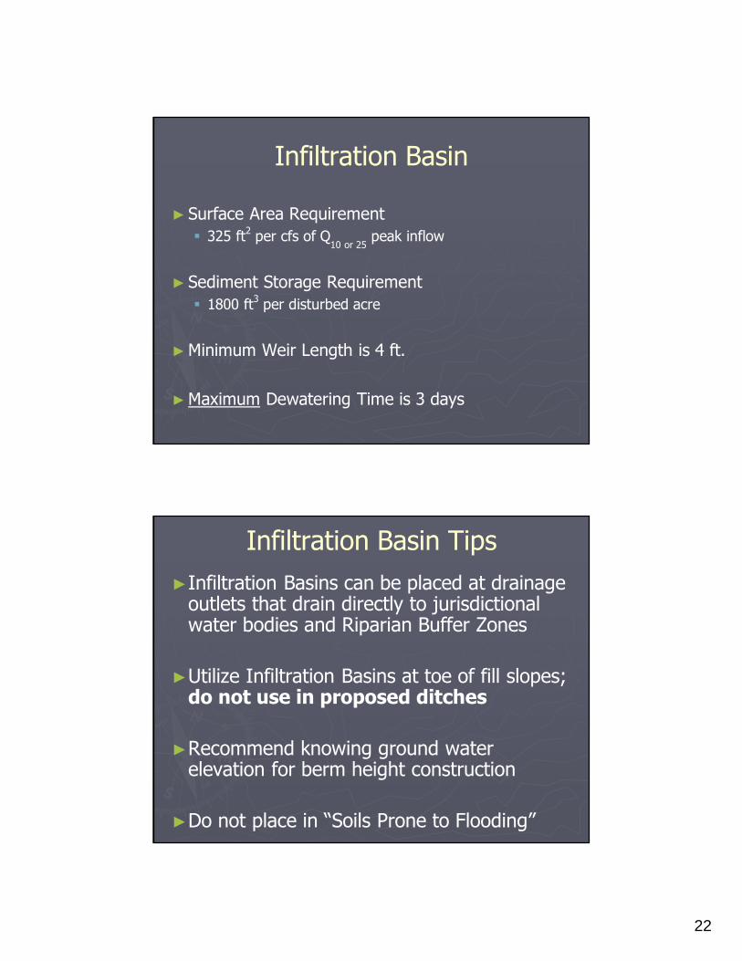
Infiltration Basin
►Surface Area Requirement
� 325 ft2per cfs of Q
10 or 25peak inflow
►Sediment Storage Requirement
� 1800 ft3per disturbed acre
►Minimum Weir Length is 4 ft.
►Maximum Dewatering Time is 3 days
Infiltration Basin Tips
►Infiltration Basins can be placed at drainage outlets that drain directly to jurisdictional water bodies and Riparian Buffer Zones
►Utilize Infiltration Basins at toe of fill slopes; do not use in proposed ditches
►Recommend knowing ground water elevation for berm height construction
►Do not place in “Soils Prone to Flooding”

23
Break!
Skimmer Devices
►Skimmer Basin
►Tiered Skimmer Basin
►Earthen Dam with Skimmer
►Stormwater Basin with Skimmer

24
Skimmer Device Update
►Removed references to “Faircloth Skimmer”
►Revised Appearance of Skimmer in Detail
►Changed “Emergency” to “Primary” Spillway
►Revised Spillway Weir Formula to Q/0.4

25
Skimmer Device Spillway Update
►Impermeable Geomembrane for Spillways
� Polypropylene
� Polyethylene
►Divisions 1, 2, 3, 4, 6
►Cost More than Soil Stabilization Geotextile
►Skimmer, Tiered Skimmer, Infiltration, Dam
Skimmer Basin Design Criteria
►Surface Area Requirement
� 325 ft2per cfs of Q
10 or 25peak inflow
►Sediment Storage Requirement
� 1800 ft3per disturbed acre
►Minimum Primary Spillway Weir Length is 4 ft.
►Minimum Dewatering Time is 24 48 hours

26
Skimmer Basin Tips
►Place Skimmer Basins at drainage outlets that drain directly to jurisdictional water bodies and Riparian Buffer Zones
►Skimmer Orifice is sized to dewater basin in 2 to 3 days in DOT Basin Design spreadsheet
►Skimmer Basins are more expensive than TRSD-B’s, but have smaller footprint
Tiered Skimmer Basin Tips
►Place Tiered Skimmer Basins at drainage outlets that drain directly to jurisdictional water bodies and Riparian Buffer Zones
►Utilize Tiered Skimmer Basin when elevation difference is greater than 6 ft. from inflow to outflow ends of basin
► Label length, width and weir dimensions of upper basin (Modified Silt Basin Type B) and lower basin

27
Earthen Dam with Skimmer Design Criteria
►Surface Area Requirement
� 325 ft2per cfs of Q
10 or 25peak inflow
►Sediment Storage Requirement
� 1800 ft3per disturbed acre
►Minimum Weir Length is 4 ft.
►Minimum Dewatering Time is 24 48 hours
Skimmer Dam Tips
►Place Earthen Dam with Skimmer in ditches with Large Cross Section (i.e. Base Ditch)
►Utilize when ditch grade is less than 2%
► Label weir length and height of designed dam
►Economic and Construction Benefits if feasible
28
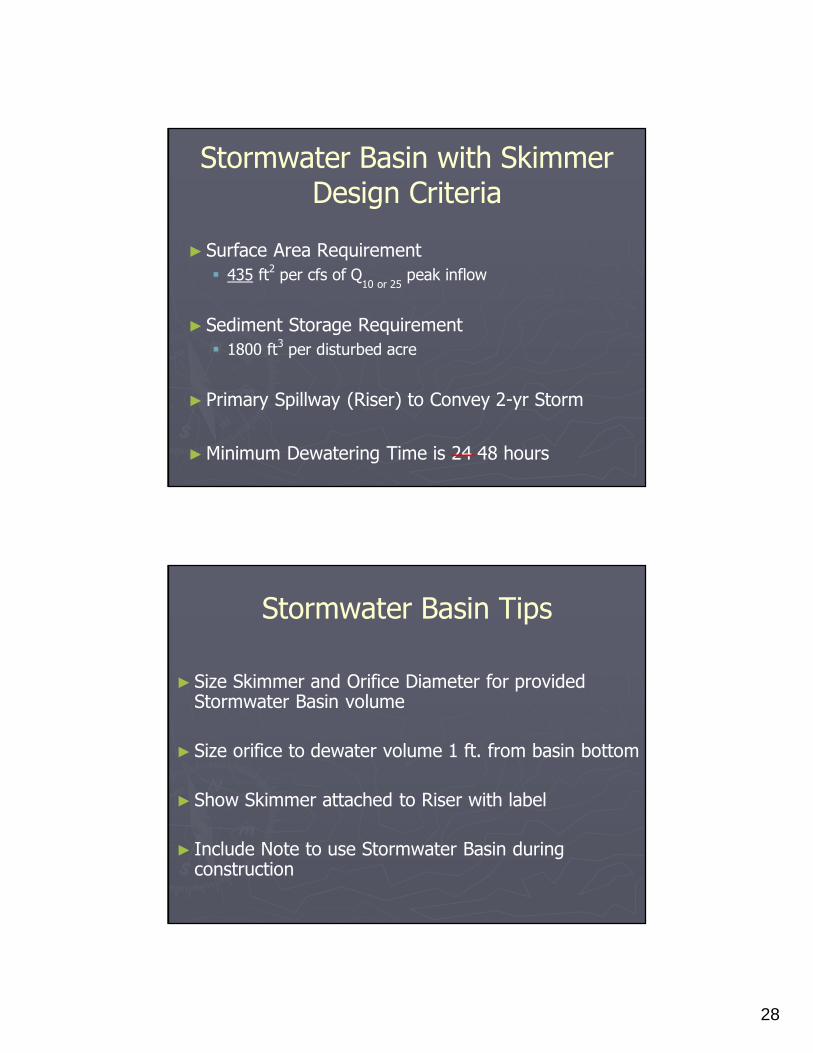
Stormwater Basin with Skimmer Design Criteria
►Surface Area Requirement
� 435 ft2per cfs of Q
10 or 25peak inflow
►Sediment Storage Requirement
� 1800 ft3per disturbed acre
►Primary Spillway (Riser) to Convey 2-yr Storm
►Minimum Dewatering Time is 24 48 hours
Stormwater Basin Tips
►Size Skimmer and Orifice Diameter for provided Stormwater Basin volume
►Size orifice to dewater volume 1 ft. from basin bottom
►Show Skimmer attached to Riser with label
► Include Note to use Stormwater Basin during construction
29
Stormwater Basin ConstructionConcerns
►Rock Layer or Water Table Too Close to Surface
►Unsuitable Material for Berms
► Inadequate Compaction in Berms
►Stormwater Basin may be too large to maintain
Stormwater Basin Construction Specs
►Minimum of 3 Baffles with Equal Spacing
►Anti-Seep Collars
ftp://ftp-fc.sc.egov.usda.gov//IL/engineer/supplements/6-36.1.pdf
►Berm Material
-Compact Embankment to at least 90% of AASHTO T 99 Test
►Specify Matting and Permanent Seed Mix for Slopes
30
When surface area and/or sediment storage requirement for a basin
cannot be achieved:
►Design sediment basin or sediment trap to the maximum practical length and width dimensions
►Utilize Polyacrylamide (PAM) devices (Wattle, Silt Check A with Matting) upgrade of the sediment basin/trap
PAM Devices
►Excelsior Wattle
►Coir Fiber Wattle
►Silt Check Type A with Matting

31
Excelsior Wattle
►Can be used with or without PAM
►When utilized, place wattles every 50 ft. in temporary and/or permanent ditches
►Use Excelsior Wattles on short term projects (one year project duration or less)
Coir Fiber Wattle
►Can be used with or without PAM
►When utilized, place coir wattles every 50 ft. in temporary and/or permanent ditches
►Use Coir Fiber Wattles on long term projects (project duration of more than a year)� Environmentally Sensitive Areas (Trout, 303(d), etc.)

32
Silt Check Type A with Matting
►When utilized, place Silt Check Type A (TRSC-A) with Matting and PAM in temporary and/or permanent ditches
►When utilized, place TRSC-A’s with Matting and PAM every 50 ft. in temporary and permanent ditches
►Use TRSC-A’s with Matting and PAM on short and long term projects where ditch grade > 2.5%
Environmentally Sensitive Areas
►50 ft. zone from top of streambank (TOB)� 50 ft. from water’s edge if TOB is not delineated on plans
►Shown inside and to ROW/Easement; do not hatch the water surface!
►Match ESA hatch spacing to ESA plan sheet note

33
ESA Locations
► DWQ High Quality Waters & Critical Area (CA) Waters� WS-I, WS-II, HQW, ORW, SA, CA
► DWQ and WRC Trout Streams
► Streams with Riparian Buffers
► Relocated Streams
► 303(d) Streams for Turbidity Impairment� 2010 Construction-related Impairments� 2012 Final 303(d) List
► Design Standards in Sensitive Watersheds Commitment
EC in Riparian Buffers
►No excavated erosion control devices inside Riparian Buffer, unless permitted by DWQ!
►Runoff treated separately inside and outside Buffer
►Protect Buffer and Stream with Perimeter EC Devices

34
Allowed EC Devices in Buffers
►Temporary Silt Fence
►Special Sediment Control Fence
►Rock Silt Checks
►Wattles
►Stone Inlet Protection
►Special Stilling Basins
Temporary Rock Silt Check Type A
►Utilize at the outlet of diversion ditches and berms for offsite runoff
►Place at the outlet of permitted ditches in Buffer Zones
►Utilize at outlet of proposed tail ditches

35
Temporary Rock Silt Check Type B
►Utilize in diversion ditches and berms for offsite runoff
►Place in any temporary and permanent ditch
►Use spacing of 250 / % ditch grade
►Use at inlets of sediment basins and driveway pipes
Type A Inlet Protection
►Use Type A Rock Inlet Sediment Traps (RIST-A, PIST-A) in high flow situations
►Utilize Type A Inlet Protection devices in medians and ditches on new alignments
►Must be at least 30 ft. from travel lane

36
Type B Inlet Protection
►Use Type B Rock Inlet Sediment Traps (RIST-B, PIST-B) in moderate flow situations
►Utilize Type B Inlet Protection devices in urban areas; widening projects
►No minimum offset distance from travel lane
Type C Inlet Protection
►Use Type C Rock Inlet Sediment Traps (RIST-C) in low to moderate flow situations
►Utilize Type C Inlet Protection devices in urban areas with C&G; widening projects
►Use RIST-C’s for fill slope drainage inlets at shoulder break points

37
Culvert/Pipe Phasing
►Provide Phasing for Pipes 48” and up
►Do not show EC design on phasing
►Make sure all phasing measures are labeled
►Be consistent with label and text language
Pipe Phasing

38
Design-Build Updates
►Vegetation Management Plan
►Field Verification of EC devices
►Monthly Field Reviews for Intermediate EC
►Approval for Modification of EC Devices

39
Vegetation Management Plan
►Narrative (Tables, Charts, etc.)
►Address Short, Mid & Long Term Stabilization
►Incorporate 7/14 Day Stabilization Timeframes
►Address ESAs – Timely and Stage Seeding
►Stage Seeding Slopes over 25 ft. in length
Field Verification of EC Devices
►After Clearing & Grubbing Measures Installed
►Monthly (Every 30 Days)
►Verify Device Drainage and Disturbed Area
►Provide Documentation of Field Verifications

40
Intermediate EC Design
Please try not to use Carolina Blue!!
Devices Requiring Calculations and Approval to Modify
►Sediment Basins (Silt Basin B, Infiltration, etc.)
►Skimmer Basin and all devices with skimmers
►Riser Basin
►Temporary Rock Sediment Dam Type A & B
►Temporary Rock Silt Check Type A
►Culvert Construction Sequence
►Temporary and Permanent Stream Channel Relocations
41
Low Impact Bridge (LIB) EC Plans
►Include Erosion Control Title Sheet
►Stabilization Timeframe Sheet required
►Utilize PAM devices
►Include all Details and Reforestation if needed
LIB Additional Info
►Checklist and Water Quality Sheet
►Cross Sections
►Permit Drawings – Draft & Final
►General Structure Drawing
42
General EC Plan Review
►Clip/Move All Labels and Notes
►Make Sure EC Measures Print on Top
►Don’t Modify EC Title Sheet
►Use Soil & Water Color Scheme for EC devices
Final EC Thoughts
►Consider Final Grade erosion control while designing Clearing & Grubbing phase
►Submit Water Quality AND Checklist sheets
►Don’t place EC devices in streams!
►Soil & Water Engineering Section is open to new ideas!
43
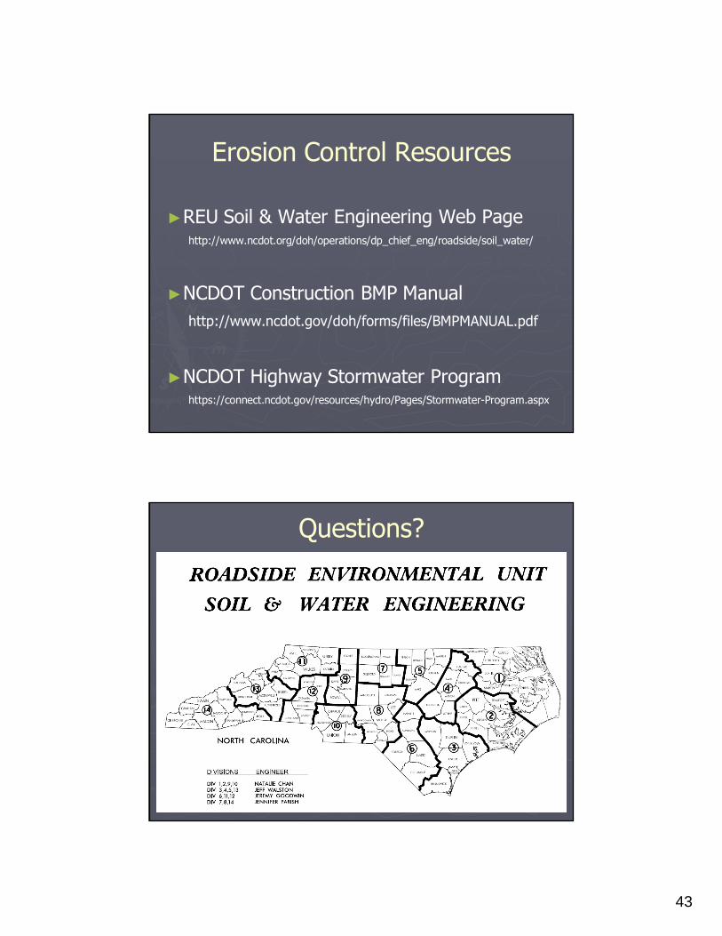
Erosion Control Resources
►REU Soil & Water Engineering Web Pagehttp://www.ncdot.org/doh/operations/dp_chief_eng/roadside/soil_water/
►NCDOT Construction BMP Manual
http://www.ncdot.gov/doh/forms/files/BMPMANUAL.pdf
►NCDOT Highway Stormwater Programhttps://connect.ncdot.gov/resources/hydro/Pages/Stormwater-Program.aspx
Questions?