acf4 1118.02 gbhydraulics-care.com/pdf/acf5_product_description.pdf · and steam turbines, hydro...
TRANSCRIPT
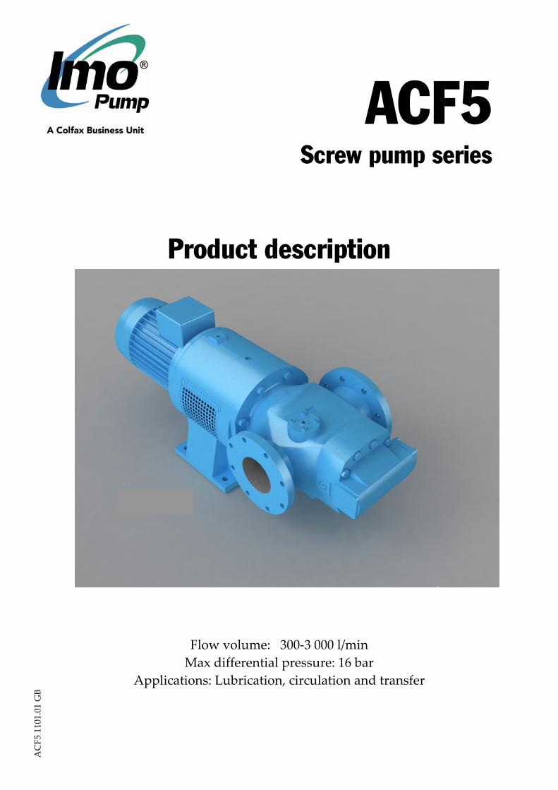
ACF5 Screw pump series
Product description
Flow volume: 300‐3 000 l/min Max differential pressure: 16 bar
Applications: Lubrication, circulation and transfer
ACF5 1101.01 GB
2 www.imo.se
AC
F5 1
101.
01 G
B
The ACF pumps are used for a number ofdifferent fluids:Lubrication oil, fuel oil, vegetable oil, hydrau-lic oil and other hydraulic fluids, glycols,polymers, emulsions, and any non-aggressivefluid with some lubricating properties.Typical applications are:• Lubrication of diesel engines, gears, gas
and steam turbines, hydro turbines, paper
machines. Main and prelube pumpfor diesel engines.
• Circulation for cooling and filtrationin large machineries and hydraulicsystems, pumping transformer oil forinsulation in transformers.
• Transfer onboard ships, in oil factories,refineries, tank farms etc.
• Filling of pressure chambers inhydraulic presses.
Applications
Viscosity, mm2/s (cSt) 2 7 12 20 30 37Max. diff. pressure (bar) 5 8 10 12 15 16
Discharge pressureMaximum discharge pressure is 16 bar
Differential pressureMaximum differential pressure is 16 bar but is reduced at low viscosities, see table below..
adjustable for different opening pressures up to 16 bar.The value of the pressure limit can be set atthe factory and should be adjusted at installa-tion (see Installation & Start-up instructionfor low pressure pumps).The maximum pressure ackumulation varieswith pump size, speed and viscosity, but willnormally not exceed 5 bar. The characteristicof the valve allows the valve to be used aspressure regulating valve when not too highdemands on pressure modulation arerequired.
DriveThe ACF -pump is designed primarily fordirect drive through a flexible shaft coupling.Under certain conditions other types of drivecan be permitted, e.g. gear or pulley drives,which create radial loads onto the shaft end.Permissible radial force varies with pressure,speed and inlet conditions.For radial load requirements, please contactIMO AB.
Inlet pressureMax. inlet pressure is 7 bar.Min. inlet pressure (suction capability) isdependent on fluid viscosity and axialvelocity of the fluid. I.e. suction capabilityincreases with decreased viscosity and rota-tion speed.Information about all specific pump per-formance can be obtained by using IMO ABpump selection program WinPump .
Displacement cm3/rSize and lead
080K 080N 090K 090N 100K 100N380 458 555 653 769 895
110L 110N 125L 125N1053 1191 1399 1748
Pressure relief valveThe pump is equipped with an integralpressure relief valve with internal return,limiting the differential pressure across thepump and protecting the pump should thedischarge line be blocked. The valve is
Technical data
www.imo.se 3
Speed The maximum speed is 1800 rpm. The operating speed may be reduced depending on inlet conditions. Please consult the pump selection program for limitations in order to avoid cavitation problems. Rotation The ACF pump is designed to operate in one rotational direction only, as standard clockwise when facing the shaft end. Pumps for CCW operation can be delivered on special request.
For shorter periods of time, a few minutes for emptying a discharge line, the pump may be operated in reverse direction, provided the back pressure is limited to 3 bar. Fluid viscosity 2‐1500 mm2/s. Viscosity up to 5000 mm2/swith approval from IMO AB. Fluid temperature Type Ixxx: ‐20°C to 90°C. Type NVxx: ‐20°C to 130°C
Sound level Typical pump sound pressure levels refer to free field conditions at a distance of 1 m from the pump. Noise of driver excluded in the quoted figures. The pressure levels are measured at a discharge pressure of 7 bar, speed 1450 rpm, viscosity 37 mm2/s. Pump Size 080 090 100 110 125 Sound level dB(A) 73 74 75 76 77 _____________________________________________________________________________ Material and design
IVXX NVXX Pump body Grey cast iron Nodular cast iron Power rotor Carbon steel Idler rotors Carbon steel Shaft seal Mechanical seal with rotating sealing ring and stationary seat in perlitic cast iron (surface treated). For handling of fluids which may be aggressive to above materials consult IMO AB. Viscosity table cSt 2 4 8 20 37 75 200 400 800 1500 SSU 32.6 39.2 52.2 99.4 174 346 927 1850 3700 6940 Units The following units are frequently used for specification of pumps:
SI‐unit IMO units USA units conversion Pressure Pa (MPa) bar psi 1 bar = 14.5 psi = 0.1 MPa Speed r/s rpm rpm 1 rpm = 0.016667 r/s Viscosity mm 2 /s cSt SSU mm 2 /s = cSt (see table) Temperature °C °C °F °C = (°F‐32)/1.8 Length m mm inch 1 mm = 0.0394 inch Flow rate m3/s lit/min GPM 1 lit/min = 0.264 USGPM
ACF5 1101.01 GB
www.imo.se 4
Performance guide
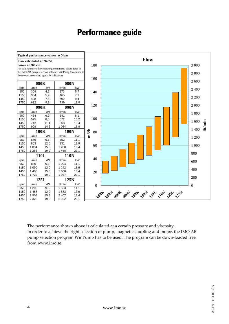
The performance shown above is calculated at a certain pressure and viscosity. In order to achieve the right selection of pump, magnetic coupling and motor, the IMO AB pump selection program WinPump has to be used. The program can be down‐loaded free from www.imo.se.
Typical performance values at 5 bar
rpm l/min kW l/min kW950 308 4,7 373 5,71150 384 5,9 465 7,11450 498 7,8 602 9,41750 612 9,8 739 11,8
rpm l/min kW l/min kW950 464 6,9 541 8,11150 575 8,6 672 10,21450 742 11,4 868 13,41750 908 14,3 1 064 16,8
rpm l/min kW l/min kW950 649 9,5 752 11,11150 803 12,0 931 13,91450 1 034 15,8 1 200 18,41750 1 265 19,9 1 468 23,1
rpm l/min kW l/min kW950 880 9,5 1 004 11,11150 1 090 12,0 1 242 13,91450 1 406 15,8 1 600 18,41750 1 722 19,9 1 957 23,1
rpm l/min kW l/min kW950 1 208 9,5 1 533 11,11150 1 488 12,0 1 883 13,91450 1 908 15,8 2 407 18,41750 2 328 19,9 2 932 23,1
125L 125N
110L 110N
Flow calculated at 26 cSt, power at 260 cStFor values under other operating conditions, please refer to the IMO AB pump selection software WinPump (download it from www.imo.se and apply for a licence).
100K 100N
080K 080N
090K 090N
Flow
0
20
40
60
80
100
120
140
160
180
080K
080N
090K
090N
100K
100N
110L
110N
125L
125N
m3/
h
0
200
400
600
800
1 000
1 200
1 400
1 600
1 800
2 000
2 200
2 400
2 600
2 800
3 000
lit/m
in
ACF5 1101.01 GB
9www.imo.se
AC
F5 1
101.
01 G
B
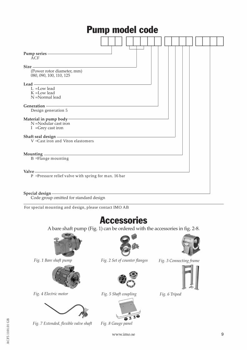
Pump model code
Pump seriesACF
Size(Power rotor diameter, mm)080, 090, 100, 110, 125
LeadL =Low leadK =Low leadN =Normal lead
GenerationDesign generation 5
Material in pump bodyN =Nodular cast ironI =Grey cast iron
Shaft seal designV =Cast iron and Viton elastomers
MountingB =Flange mounting
ValveP =Pressure relief valve with spring for max. 16 bar
Special designCode group omitted for standard design
Accessories
Fig. 1 Bare shaft pump Fig. 2 Set of counter flanges Fig. 3 Connecting frame
Fig. 4 Electric motor
A bare shaft pump (Fig. 1) can be ordered with the accessories in fig. 2-8.
Fig. 5 Shaft coupling
Fig. 7 Extended, flexible valve shaft Fig. 8 Gauge panel
Fig. 6 Tripod
For special mounting and design, please contact IMO AB
www.imo.se 6
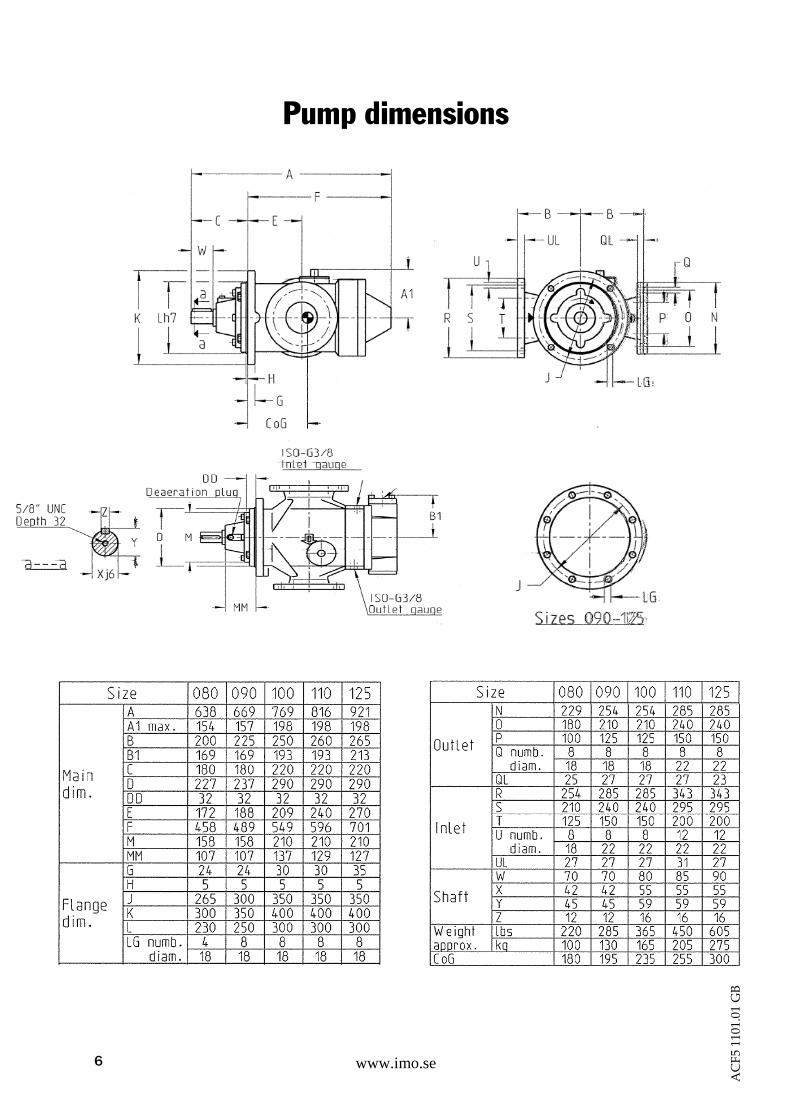
Pump dimensions
ACF5 1101.01 GB

www.imo.se 7
Pump dimensions
ACF5 1101.01 GB
www.imo.se 8
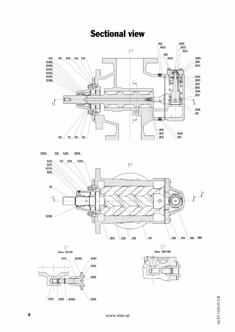
Sectional view
ACF5 1101.01 GB
www.imo.se 9
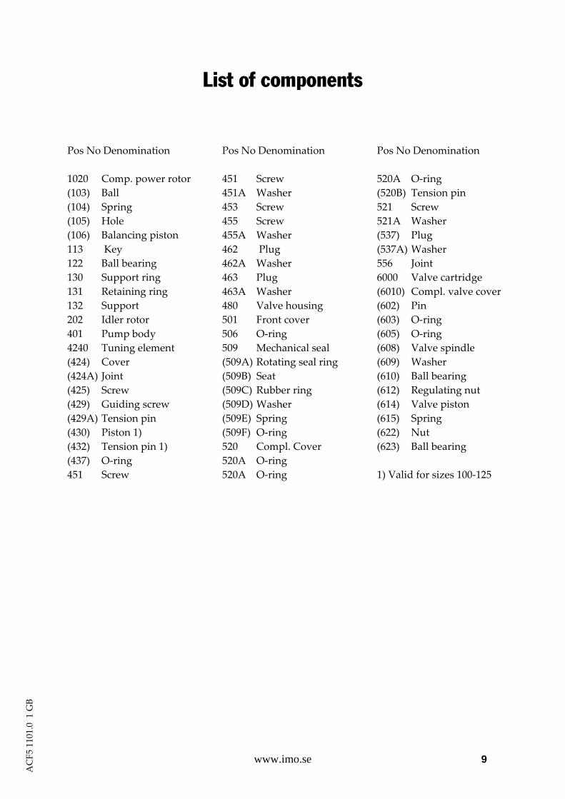
List of components
Pos No Denomination 1020 Comp. power rotor (103) Ball (104) Spring (105) Hole (106) Balancing piston 113 Key 122 Ball bearing 130 Support ring 131 Retaining ring 132 Support 202 Idler rotor 401 Pump body 4240 Tuning element (424) Cover (424A) Joint (425) Screw (429) Guiding screw (429A) Tension pin (430) Piston 1) (432) Tension pin 1) (437) O‐ring 451 Screw
Pos No Denomination 451 Screw 451A Washer 453 Screw 455 Screw 455A Washer 462 Plug 462A Washer 463 Plug 463A Washer 480 Valve housing 501 Front cover 506 O‐ring 509 Mechanical seal (509A) Rotating seal ring (509B) Seat (509C) Rubber ring (509D) Washer (509E) Spring (509F) O‐ring 520 Compl. Cover 520A O‐ring 520A O‐ring
Pos No Denomination 520A O‐ring (520B) Tension pin 521 Screw 521A Washer (537) Plug (537A) Washer 556 Joint 6000 Valve cartridge (6010) Compl. valve cover (602) Pin (603) O‐ring (605) O‐ring (608) Valve spindle (609) Washer (610) Ball bearing (612) Regulating nut (614) Valve piston (615) Spring (622) Nut (623) Ball bearing 1) Valid for sizes 100‐125
ACF5 1101.01 GB
10 www.imo.se
AC
F5 1
101.
01 G
B
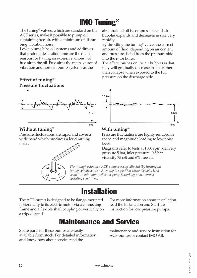
The tuning® valve on a ACF-pump is easily adjusted (by turning thetuning spindle with an Allen key to a position where the noise levelcomes to a minimum) while the pump is working under normaloperating conditions.
The tuning® valves, which are standard on theACF series, make it possible to pump oilcontaining free air, with a minimum of distur-bing vibration noise.Low volume lube oil systems and additivesthat prolong deaeration time are the mainreasons for having an excessive amount offree air in the oil. Free air is the main source ofvibration and noise in pump systems as the
IMO Tuning®
Effect of tuning®
Pressure fluctuations
Without tuning®
Pressure fluctuations are rapid and cover awide band which produces a loud rattlingnoise.
With tuning®
Pressure fluctuations are highly reduced inspeed and magnitude leading to low noiselevel.Diagrams refer to tests at 1800 rpm, deliverypressure 5 bar, inlet pressure -0,5 bar,viscosity 75 cSt and 6% free air.
air entrained oil is compressible and airbubbles expands and decreases in size veryrapidly.By throttling the tuning® valve, the correctamount of fluid, depending on air contentand pressure, is fed from the pressure sideinto the rotor bores.The effect this has on the air bubbles is thatthey will gradually decrease in size ratherthan collapse when exposed to the fullpressure on the discharge side.
InstallationThe ACF-pump is designed to be flange-mountedhorizontally to its electric motor via a connectingframe and a flexible shaft coupling or vertically ona tripod stand.
Maintenance and ServiceSpare parts for these pumps are easilyavailable from stock. For detailed informationand know-how about service read the
maintenance and service instruction forACF-pumps or contact IMO AB.
For more information about installationread the Installation and Start-upinstruction for low pressure pumps.

www.imo.se 11
ACF5 1101.01 GB
IMO AB: P. O. Box 42090, SE 126 14 Stockholm, Sweden Telephone: +46 8 50 622 800, Telefax: +46 8 645 1509
www.imo.se