acha / achba self-contained horizontal units air to air
TRANSCRIPT

INSTALLATION, OPERATION AND MAINTENANCE INSTRUCTIONS
ACHA / ACHBASELF-CONTAINED HORIZONTAL UNITS AIR TO AIR
ACHA - Cooling only ACHBA - Heat pump
CCHA / ECHA - CCHBA / ECHBASPLIT HORIZONTAL UNITS AIR-AIR
CCHA / ECHA - Cooling onlyCCHBA / ECHBA - Heat pump

- ACHA / ACHBA
Pages 1 - 28
- CCHA / ECHA - CCHBA / ECHBA
Pages 29 - 52
CATALOGS SUMMARY

Installation, operation and maintenance instructions
ACHA / ACHBASELF-CONTAINEDHORIZONTALUNITSMONOBLOCAIR-AIR ACHA-CoolingOnly ACHBA-HeatPump


3
1. INTRODUCTION.................................................................................................................................................................................. 4
2. SAFETY PRECAUTIONS ................................................................................................................................................................. 5
3. RECEPTION.
. . 3.1..Inspection.upon.receipt............................................................................................................................................................ 6
. . 3.2..Rigging................................................................................................................................................................................................ 6
. . 3.3..Storage................................................................................................................................................................................................ 6
4. INSTALLATION LOCATION.
. . 4.1..Service.area.(mm)......................................................................................................................................................................... 7
. . 4.2..Weight.distribution.(kg)........................................................................................................................................................... 7
. . 4.3..Unit.settlement.............................................................................................................................................................................. 7
5. START UP
. . 5.1..Operation.limits............................................................................................................................................................................. 8
. . 5.2..Electrical.data.................................................................................................................................................................................. 9
. . 5.3..Drainage.......................................................................................................................................................................................... 10
. . 5.4..Air.ducts.......................................................................................................................................................................................... 10
. . 5.5..Adjustment.of.fan.transmision......................................................................................................................................... 11
. . 5.6..Compressor.lubricant.............................................................................................................................................................. 11
6. TECHNICAL DATA............................................................................................................................................................................. 12
7. DIMENSIONS........................................................................................................................................................................................ 14
8. REFRIGERANT CHARGE............................................................................................................................................................... 21
9. MAINTENANCE.................................................................................................................................................................................. 22
10. APPENDIX: SAFETY DATA R410A........................................................................................................................................ 17
INDEX
Visit.our.website.and.register.in.order.to.obtain.technical.documentation.of.these.products.as.well.as.of.the.rest.of.the.Hitecsa.range.
www.hitecsa.com
InStAllAtIOn,.OpERAtIOn.AnD.MAIntEnAnCE.InStRUCtIOnS.-.ACHA / ACHBA
4
1. INTRODUCTION
The contents of this manual are designed to assure the correct installation, adjustment and maintenance of the unit, therefore:.
•.Read.the.instructions.with.due.care.and.attention.
•.the.appliance.must.be.installed,.tested.and.serviced.by.properly.qualified.staff.licensed.in.accordance.with.the.established.legislation..
•.the.manufacturer.declines.all. liability.and.warranty.coverage. is.automatically.waived,. if.electrical.and/or.mechanical.modifications.to.the.unit..tampering.and.unauthorized.repairs.or.modifications.to.the.unit.will.automatically.void.the.warranty.
•.Observe.the.safety.regulations.in.force.at.the.time.of.installation.
•.Make.sure.that.the.characteristics.of.the.mains.network.conform.to.the.data.on.the.serial.number.plate.placed.on.the.unit.
•.Keep.this.manual.and.the.wiring.diagram.with.care.and.make.sure.that.they.are.available.for.consultation.by.the.operator.whenever.necessary.
•.packing.materials.(plastic.wrappings,.expanded.polystyrene,.etc).are.potentially.hazardous.and.must.be.kept.out.of.reach.of.children..Recycle.packing.materials.in.accordance.with.local.legislation..
•.the.units.must.be.used.only.for.the.purpose.for.which.they.are.designed..the.manufacturer.bears.no.res-ponsibility.in.the.case.of.applications.other.than.the.specified.use.
•.Disconnect.the.unit.in.the.event.of.breakdowns.or.malfunctions.
•.If.repairs.are.necessary,.use.only.HItECSA.approved.service.centres.and.always.insist.on.original.spare.parts..the.use.of.non-original.parts.and/or.unauthorized.service.centres.may.result.in.unsafe.operation.of.the.unit.
Regulations and certifications
ISO 9001:2008 CERTIFICATION:.HItECSA.AIRE.ACOnDICIOnADO.S.l.U.,.trying.always.to.find.the.customer.satisfaction,.has.obtained.the.ISO.9001:2008.Quality.System.referred.to.its.production.activity..this.will.results.in.a.continuous.determination.to.improve.quality.and.reliability.of.all.our.products;.commercial.activities,.de-sign,.raw.materials,.production.and.after-.sales.service,.are.the.means.to.reach.our.goal..
CE MARkING:.Our.machines.have.got. the.CE.mark,. in.conformity.with. the.essential. requirements.of. the.applicable.EC.directives.and.their.last.modifications.as.well.as.with.the.national.legislation.of.each.country.

5
2. SAFETY PRECAUTIONS
•. Installation.and.maintenance.of.air.conditioning.equipment.can.be.dangerous.because.the.system.is.under.pressure,.because.some.of.its.elements.have.high.temperatures.and.include.electrical.components.
•.Only.qualified.and.trained.service.staff.should.install,.commission.and.carry.out.maintenance.works..Unqua-lified.staff.should.only.carry.out.basic.tasks.such.as.cleaning.and.replacement.of.filters,.etc.
•. In.every.visit,.all.precautions.should.be.taken.into.account:.those.recommended.in.the.Installation,.operation.and.maintenance.instructions,.as.well.as.the.ones.indicated.in.labels.of.the.unit..Do.not.forget.to.strictly.follow.any.other.safety.codes.
•.Use.safety.glasses,.work.gloves.and.any.other.safety.accessory.necessary.
•.For.brazing.operations.use.a.quenching.cloth.and.have.at.close.distance.a.fire.extinguisher.
•.When.repairing.the.unit,.use.only.original.spare.parts.and.install.them.properly.in.the.same.position.where.old.parts.were.placed.
•.Do.not.install.the.unit..in.explosive.atmosphere.
WARNING!
Before starting installation, service or maintenance, turn off the main power switch in order to avoid electrical shock that may cause personal damages.

InStAllAtIOn,.OpERAtIOn.AnD.MAIntEnAnCE.InStRUCtIOnS.-.ACHA / ACHBA
6
3. RECEPTION
3.1 Inspection upon receipt
•.Units.are.delivered.with.special.protective.packing;.therefore.when.it.arrives,.please.inspect.it.carefully.to.check.that.no.damage.has.occurred.during.transport.and.that.the.unit.has.been.supplied.complete.with.all.parts.specified.in.the.order..If.any.damage.is.found,.immediately.file.a.claim.with.the.transport.company..
•.Verify.the.correct.voltage.of.the.nameplate.and.make.sure.it’s.in.accordance.with.local.power.supply..
•. In.case.of.any.flaw.or.anomaly.detected,.please.contact.HItECSA
3.2 Rigging
•.Before.moving.the.unit,.make.sure.that.all.panels.are.well.fixed.
•.Raise.and.set.down.the.equipment.carefully.
•.Do.not.tilt.the.unit.more.than.15.degrees.during.transportation.
•.When.lifting.the.unit,.make.sure.that.it’s.balanced.and.stable;.bear.in.mind.that.the.heaviest.part.is.where.the.compressor.is.installed.
•.Check.minimum.length.of.wire.raising.
3.3 Storage
If.the.equipment.is.going.to.be.stored.please.follow.the.instructions.below.in.order.to.avoid.damages,.corrosion.or.deterioration:
•.Keep.the.unit.away.from.direct.sunlight,.rain,.sand,.wind.or.temperatures.above.50ºC
•.Storage.temperature:.maximum.50ºC,.minimum.-10ºC
•.Maximum.humidity:.90%
Fig. 2Fig. 1

7
4. INSTALLATION LOCATION
•.Check.if.the.base.is.able.to.support.the.weight.of.unit.during.operation.
•.Reserve.a.minimum.service.area.according.to.Fig..2.
•.Choose.a.place.free.of.dust.or.any.other.foreign.material.that.could.clog.or.damage.the.condenser.coil..the.location.should.also.be.a.place.that.cannot.be.flooded.
•.Consult.and.respect.all.regulations.concerning.installation.of.air.conditioning.systems.
•.Check.if.sound.waves.do.not.disturb.anyone.
4.1 Service area (mm)
4.2 Weight distribution (kg)
4.3 Unit settlement
•.Make.sure.that.the.unit.is.correctly.levelled.
•.the.bed.frame.should.be.strong.and.solid.enough.to.support.the.weight.of.the.machine.
•.Verify.that.the.indoor.drain.is.working.properly.
MODEL 1 2 3 4 TOTAL
.. 201. 62. 25. 37. 35. 159
. 251. 55. 28. 42. 39. 163
.. 351. 73. 39. 51. 51. 214
.. 371. 87. 44. 64. 58. 253
.. 401. 87. 45. 65. 57. 253
.. 501. 97. 50. 68. 53. 266
. 701. 94. 77. 135. 78. 384
. 721. 94. 79. 131. 80. 384
.. 751. 95. 83. 144. 80. 402
.. 801. 107. 80. 110. 111. 408
.. 1001. 108. 81. 113. 125. 427
. 1201. 113. 100. 132. 138. 483 Fig. 4
Fig. 3
Models 201-751
Models 801-1201
Condenser
Evaporator

InStAllAtIOn,.OpERAtIOn.AnD.MAIntEnAnCE.InStRUCtIOnS.-.ACHA / ACHBA
8
5. START UP
•.Start.up.should.be.performed.by.qualified.technical.people.
•.Use.a.start.up.check.list:.record.inlet.and.outlet.temperatures.and.pressures,.outdoor.air.temperature,.volts.
and.amps.of.each.compressor.and..each.fan.motor,.suction.and.discharge.pressure.of.each.compressor.
•.Use.a.similar.check.list.for.service.and.maintenance.works.
•Remember.that.after.4.hours.of.operation,.it.is.necessary.to.clean.the.filters..
•.Monitor.at.least.3.cooling.cycle.operations..
1. Mainpower400/3/50+neutral2. Earth3. Crankcaseheater(230/1/50)4. Time-delayfusesorcircuitbreaker(MCB)curveD5. Mainpowerswitch6. Remotecontrol
BEFORE START UP
Check the following points:• Wiresarewelltightened.
•Panelsarefirmlysecuredwithscrews.
•Therearenooilorrefrigerantleaks.
•Theunitiscorrectlylevelled.
•Thereisenoughspaceforserviceandmaintenance.
•Drainageisnotblocked.
•Crankcaseheaterhasbeenworkingatleast24hourspriortothestart-up.
•Airfiltersarecleanandcorrectlymounted.
•Grilles,airdiffusers,airductsandflexibleconnectionsareingoodcondition.
•Electricalpowersourceisinaccordancewithwhatissaidinthenameplate.
•Fansrotateintherightdirection.
Fig. 5
OUTDOOR UNITINDOOR UNIT

9
5.1 Operation limits
Units.can.operate.at.a.maximum.altitude.of.1.500.meters.For.other.conditions,.please.consult.
•.Main.power.supply.of.the.unit.should.agree.with.the.data.shown.on.the.nameplate..HItECSA.will.not.be.held.responsible.for.damages.resulted.from.non.observance.of.the.above.
•.Always.use.the.wiring.diagram.sent.with.the.unit.to.make.electrical.connections
•.Check.that.the.crankcase.heater.has.been.working.at.least.24.hours.prior.to.the.start.up.of.the.unit.
•.Current.supply.should.be.within.10%.of.Volts.and.Amperes.indicated.on.the.unit.nameplate..
•.Do.not.operate.the.unit.at.different.current.from.that.shown.on.the.unit.nameplate.
•..the.installer.should.put.line.protection.elements.in.compliance.with.current.legislation.
•.the.interconnecting.wires.should.be.protected.with.a.tube.or.put.inside.a.groove.channel...
5.2 Electrical data
COOLING
Standard
Minimum
Maximum
HEATING
Standard
Minimum
Maximum
ºC ºC ºC ºC.
. 35. 24. 27. 19
. 20. -. 20. 15.
. 45. -. 32. 23
OUTDOORAIR INDOORAIR
DRY WET DRY WET
ºC ºC ºC ºC.
. 7. 6. 20. -
. -6. -7. 10. -.
. 24. 18. 26. -
WARNING!
Before starting installation, service or maintenance, turn off the main power switch in order to avoid electrical shock that may cause personal damages.
ACHA - ACHBA
Voltage
total.input.power.(1)
total.input.current.(1)
total.input.power.(2)
total.input.current.(2)
total.input.power.(3)
total.input.current.(3)
total.input.power.(4)
total.input.current.(4)
Starting.current
Circuit.breaker.curve.D*
Min..wire.section.(227.CEI.53)
201 251 351 371 401 501. V.(50Hz). 230.1. 230.1. 230.1/400.3+n. 400.3+n. 400.3+n. 400.3+n.
. kW. 2,8. 3,4. 4,3. 5,0. 5,2. 6,5
. A. 14,6. 20,4. 12,1. 15,3. 15,4. 14,6
. kW. 3,5. 4,1. 5,3. 6,9. 7,1. 9,2.
. A. 15,9. 18,5. 12,8. 16,8. 16,8. 16,6
. kW. 2,8. 3,25. 3,8. 4,8. 5,1. 6,4.
. A. 13,3. 18,9. 11,9. 14,8. 15,1. 13,4.
. kW. 3,4. 4,3. 4,8. 5,8. 6,5. 8,5
. A. 15,2. 19,4. 12,8. 15,8. 16,4. 15,5.
. A. 63. 96. 43. 63. 63. 66
. A. 20. 20. 15. 15. 20. 20
. mm2. 2,5. 4. 2,5. 2,5. 2,5. 2,5

InStAllAtIOn,.OpERAtIOn.AnD.MAIntEnAnCE.InStRUCtIOnS.-.ACHA / ACHBA
10
. nOtES:.
. . 1..Cooling.:.Outdoor.air.temperature..35ºC...Indoor.air.temperature.(WB)..19ºC.
. . 2..Cooling.(max).:.Outdoor.air.temperature..46ºC..Indoor.air.temperature.(WB)..21ºC.
. . 3..Heating.:.Outdoor.air.temperature.(WB)..6ºC..Indoor.air.temperature..20ºC.
. . 4..Maximo.calor.:.Outdoor.wet.temperature..18ºC..Indoor.air.temperature..26ºC.
. *Recommendation.to.the.installer
5.3 Drainage
ACHA - ACHBA
Voltage
total.input.power.(1)
total.input.current.(1)
total.input.power.(2)
total.input.current.(2)
total.input.power.(3)
total.input.current.(3)
total.input.power.(4)
total.input.current.(4)
Starting.current
Circuit.breaker.curve.D*
Min..wire.section.(227.CEI.53)
701 721 751 801 1001 1201. V.(50Hz). 400.3+n. 400.3+n. 400.3+n. 400.3+n. 400.3+n. 400.3+n.
. kW. 7,8. 8,5. 9,5. 9,7. 12,4. 15,1
. A. 16,9. 18,6. 20,2. 20,3. 24,5. 32,0
. kW. 10,9. 12,0. 13,2. 13,3. 17,0. 20,3.
. A. 18,6. 21,0. 22,2. 22,2. 29,1. 34,0
. kW. 6,9. 7,9. 8,1. 8,8. 11,8. 14,4.
. A. 14,4. 16,5. 18,9. 19,2. 23,0. 31,5.
. kW. 9,4. 10,2. 12,4. 12,0. 16,4. 19,5
. A. 18,4. 19,1. 21,1. 20,6. 27,0. 33,3.
. A. 67. 96. 96. 96. 96. 158
. A. 25. 25. 25. 25. 30. 40
. mm2. 4. 4. 4. 4. 6. 10
•. Indoor.drainage.(of.condensate.water).has.a.3/4”.Mpt.connection.
•.Condensate.drain.line.diameter.should.be.equal.or.larger.than.the.unit.connection.depending.on.line.length.and.general.building.configuration..
•.Drainage.line.should.have.a.minimum.inclination.of.2%.for.proper.water.evacuation.
•.When. drainage. line. is. exposed. to. temperatures.below.0ºC,. it. is.necessary. to.provide. thermal. in-sulation.or.electrical.heating.wire.to.avoid.water.freezing.and.tube.damages
•. It.is.advisable.to.install.a.trap.with.proper.dimensions..Fig. 6
Dimensions
5.4 Air ducts
•.Air.duct.dimensions.will.be.determined.according.to.the.airflow.and.available.static.pressure..
•.Ducts.must.be.designed.by.qualified.technical.people..
•.Use.ducts.made.of.non-inflammable.materials.in.order.to.avoid.any.emission.of.gas.in.case.of.fire..It.is.ad-visable.to.use.metal.plate.duct.with.insulation..
•.Use.flexible.ducts.to.connect.air.ducts.into.the.unit.and.thus.avoid.vibration.and.noise.transmission.

11
5.5 Adjustment of fan transmission
•.Adjust.transmission.so.that.indoor.fan-motor.reaches.its.nominal.value.
•. If.consumption.is.lower.than.the.nominal.value,.the.airflow.is.insufficient.
- To change fan speed: 1. Remove.the.belt.and.slide.the.motor.over.the.channel... 2.. loosen.setscrews.and.turn.the.mobile.flap.around,.depending.on.your.needs.. 3.. tight.setscrews... 4.. put.the.belt.back.in.the.pulley’s.channel.. 5.. tight.the.belt.using.a.tension.adjuster.screw..
- To line up motor and fan pulleys: 1. Loosen.setscrews.from.the.fan.pulley.. 2.. Slide.the.fan.pulley.down.the.axe.and.line.up.with.the.motor,.using.a.ruler.to.make.sure.that.it’s.in.parallel... . with.the.belt... 3.. tight.the.fan.pulley.using.a.tension.adjuster.crew..
5.6 Compressor lubricant
Compressors.with.R410a.refrigerant.use.synthetic.polyester.oil,.each.manufacturer.using.a.specific.oil.for.his.pro-duct...the.system.must.not.remain.open.to.the.atmosphere.more.than.15.minutes..Due.to.its.hygroscopic.qualities,.you.must.be.very.careful.during.manipulation:.when.synthetic.oils.mix.up.with.mineral.oil,.they.deteriorate.causing.obstructions.and.even.the.breakdown.of.the.compressor..Do.not.mix.them.under.any.circumstance..
Fig. 7
1.-Motor.2.-Motorpulley.3.-Belt.4.-Fanpulley.5.-Tensoradjustmentscrew.6.-Setscrew.7.-Mobileflap.8.-Fixflap.
Fig. 8
RIGHT POSITION OF RULER
WRONG ALIGNMENT
WRONG
WRONG

InStAllAtIOn,.OpERAtIOn.AnD.MAIntEnAnCE.InStRUCtIOnS.-.ACHA / ACHBA
12
6. TECHNICAL DATA
ACHA / ACHBA
CAPACITIES
Cooling.capacity.(1)
EER.Efficiency
Heating.capacity.(2)
COp.Efficiency
COMPRESSOR
type
Voltage.
Operating.refrigerant.charge.R410A
Input.power.(COOlInG)
Input.current.(COOlInG)
Input.power.(HEAtInG)
Input.current.(HEAtInG)
INDOORHEATEXCHANGER
type.
Frontal.surface
Fins.size
piping.diameter
OUTDOORHEATEXCHANGER
type.
Frontal.surface
Fins.size
piping.diameter
INDOORFAN
type.
Model.
Motor.power
Voltage
Absorbed.current.
OUTDOORFAN
type.
Model.
Motor.power
Voltage
Absorbed.current.
DIMENSIONSANDWEIGHT
length
Width
Height
Weight
201 251 351 371 401 501
.
. kW. 5,6. 7,4. 9,7. . 11,6. 12,4. 14,1
. . 2,0. 2,2. 2,2. . 2,3. 2,4. 2,2
. kW. 6,1. 8,2. 9,8. . 12,0. 13,8. 16,4
. . 2,4. 2,5. 2,6. . 2,7. 2,9. 2,8
. . Rotatif. Rotatif. Rotatif. . Scroll. Scroll. Scroll
. V. 230.1. 230.1. 230.1/400.3+n.. 400.3+n. 400.3+n. 400.3+n
. kg. 2,2. 2,7. 3,8. . 4,0. 4,1. 5,0
. kW. 2,8. 3,4. 4,3. . 5,0. 5,2. 6,5
. A. 9,6. 4,6. 5,5. . 7,6. 7,9. 9,7
. kW. 2,8. 3,25. 3,8. . 4,8. 5,1. 6,4
. A. 8,3. 4,4. 4,9. . 6,8. 7,1. 8,5
. . ...........................Aluminum.fins.and.copper.tubing
. m2. 0,20. 0,25. 0,25. . 0,31. 0,31. 0,31
. mm. 2,1. 2,1. 1,8. . 2,1. 2,1. 2,1.
. mm. 3/8. 3/8. 3/8. . 3/8. 3/8. 3/8
. ............................................Aluminum.fins.and.copper.tubing
. m2. 0,22. 0,292. 0,36. . 0,4. 0,4. 0,4
. mm. 1,8. 1,8. 1,8. . 1,8. 1,8. 1,8
. mm. 3/8. 3/8. 3/8. . 3/8. 3/8. 3/8
. .............Centrifugal,.double.suction
. . 9/7.DD. 9/9.DD. 10/10.DD. . 10/10.DD. 10/10.DD. 10/10.SS
. kW. 0,120. 0,250. 0,250. . 0,373. 0,373. 0,550
. V. 230-1. 230-1. 230-1. . 230-1. 230-1. 400-3
. A. 1,6. 1,5. 1,9. . 2,6. 2,7. 1,6
. .............Centrifugal,.double.suction
. . 9/9.DD. 10/10.DD. 10/10.DD. . 12/9.DD. 12/9.DD. 12/9.DD
. kW. 0,37. 0,37. 0,44. . 0,55. 0,55. 1,10
. V. 230-1. 230-1. 230-1. . 230-1. 230-1. 400-3
. A. 4,0. 4,0. 4,3. . 4,8. 4,7. 3,0
. mm. 1.175. 1.325. 1.405. . 1.455. 1.455. 1.455
. mm. 1.109. 1.252. 1.339. . 1.389. 1.389. 1.389
. mm. 452. 504. 504. . 562. 562. 562
. kg. 159. 163. 214. . 253. 266. 266
(1).COOlInG:.Outdoor.temperature:.35.°C..Indoor.WB.temperature:.19.°C..(2).HEAt.pUMp:.WB.outdoor.temperature:.6.°C..Indoor.temperature:.20.°C..

13
ACHA / ACHBA
CAPACITIES
Cooling.capacity.(1)
EER.Efficiency
Heating.capacity.(2)
COp.Efficiency
COMPRESSOR
type
Voltage.
Operating.refrigerant.charge.R410A
Input.power.(COOlInG)
Input.current.(COOlInG)
Input.power.(HEAtInG)
Input.current.(HEAtInG)
INDOORHEATEXCHANGER
type.
Frontal.surface
Fins.size
piping.diameter
OUTDOORHEATEXCHANGER
type.
Frontal.surface
Fins.size
piping.diameter
INDOORFAN
type.
Model.
Motor.power
Voltage
Absorbed.current..
OUTDOORFAN
type.
Model.
Motor.power
Voltage
Absorbed.current.
DIMENSIONSANDWEIGHT
length
Width
Height
Weight
701 721 751 801 1001 1201
.
. kW. 17,2. 18,5. 20,8. . 21,9. 28,4. 33,5
. . 2,0. 2,2. 2,2. . 2,3. 2,3. 2,1
. kW. 18,9. 20,4. 21,9. . 24,6. 29,8. 37,2
. . 2,8. 2,6. 2,7. . 2,8. 2,5. 2,5
. . . . . Scroll
. V. 400.3+n. 400.3+n. 400.3+n. . 400.3+n. 400.3+n. 400.3+n
. kg. 5,7. 5,7. 5,9. . 6,7. 9,0. 9,5
. kW. 7,8. 8,5. 9,5. . 9,7. 12,4. 15,1
. A. 10,9. 12,8. 14,5. . 14,5. 18,0. 19,0
. kW. 6,9. 7,9. 8,1. . 8,8. 11,8. 14,4
. A. 9,3. 11,7. 13,2. . 12,9. 16,0. 17,9
. . ..................... ............Aluminum.fins.and.copper.tubing
. m2. 0,47. 0,47. 0,47. . 0,54. 0,65. 0,77
. mm. 1,8. 1,8. 1,8. . 1,8. 1,8. 1,8.
. mm. 3/8. 3/8. 3/8. . 3/8. 3/8. 3/8
. ............. .....................................Aluminum.fins.and.copper.tubing
. m2. 0,605. 0,605. 0,605. . 0,605. 0,9. 1,19
. mm. 1,8. 1,8. 1,8. . 1,8. 1,8. 1,8
. mm. 3/8. 3/8. 3/8. . 3/8. 3/8. 3/8
. .............Centrifugal,.double.suction
. . 12/9.SS. 12/9.SS. 12/9.SS. . 12/9.SS. 12/12.SS. 15/15.SS
. kW. 0,735. 0,735. 0,735. . 0,735. 1,5. 1,5
. V. 400-3+n. 400-3+n. 400-3+n. . 400-3. 400-3. 400-3
. A. 2,0. 2,0. 2,1. . 2,3. 3,0. 3,0
. ............Centrifugal,.double.suction
. . 12/12.DD. 12/12.DD. 12/12.SS. . 12/12.SS. 12/12.SS. 15/15.SS
. kW. 1,10. 1,10. 1,50. . 1,50. 2,20. 3,00
. V. 400-3. 400-3. 400-3. . 400-3. 400-3. 400-3
. A. 3,5. 3,5. 3,4. . 3,6. 4,7. 6,6
. mm. 1.755. 1.755. 1.755. . 1.755. 1.755. 2.400
. mm. 1.697. 1.697. 1.697. . 1.697. 1.950. 2.193
. mm. 640. 640. 640. . 640. 662. 782
. kg. 384. 384. 402. . 408. 425. 620
(1).COOlInG:.Outdoor.temperature:.35.°C..Indoor.WB.temperature:.19.°C..(2).HEAt.pUMp:.WB.outdoor.temperature:.6.°C..Indoor.temperature:.20.°C..

InStAllAtIOn,.OpERAtIOn.AnD.MAIntEnAnCE.InStRUCtIOnS.-.ACHA / ACHBA
14
7. DIMENSIONS MODEL 201
LEG
EN
D
1.
Com
pres
sor
2.
Out
door
hea
texc
hang
er3
.In
door
hea
texc
hang
er4
.E
lect
ricb
ox5
.In
door
fan
6.
Indo
orfa
nm
otor
7.
Out
door
fan
mot
or8
.O
utdo
orfa
n9
.A
irfil
ter
10.
Indo
ord
rain
age
3/4”
mal
e11
.E
xter
nalv
alve
sfo
rpr
essu
rete
st12
.In
putp
ower
sup
ply
13.
Out
door
dra
inag
e3/
4”m
ale
Stand
ard
Optional

15
DIMENSIONS
MODELS 251 - 271
LEG
EN
D
1.
Com
pres
sor
2.
Out
door
hea
texc
hang
er3
.In
door
hea
texc
hang
er4
.E
lect
ricb
ox5
.In
door
fan
6.
Indo
orfa
nm
otor
7.
Out
door
fan
mot
or8
.O
utdo
orfa
n9
.A
irfil
ter
10.
Indo
ord
rain
age
3/4”
mal
e11
.E
xter
nalv
alve
sfo
rpr
essu
rete
st12
.In
putp
ower
sup
ply
13.
Out
door
dra
inag
e3/
4”m
ale
Stand
ard
Optional

InStAllAtIOn,.OpERAtIOn.AnD.MAIntEnAnCE.InStRUCtIOnS.-.ACHA / ACHBA
16
DIMENSIONS
MODEL 351
LEG
EN
D
1.
Com
pres
sor
2.
Out
door
hea
texc
hang
er3
.In
door
hea
texc
hang
er4
.E
lect
ricb
ox5
.In
door
fan
6.
Indo
orfa
nm
otor
7.
Out
door
fan
mot
or8
.O
utdo
orfa
n9
.A
irfil
ter
10.
Indo
ord
rain
age
3/4”
mal
e11
.E
xter
nalv
alve
sfo
rpr
essu
rete
st12
.M
ain
switc
h13
.In
putp
ower
sup
ply
14.
Out
door
dra
inag
e3/
4”m
ale
Stand
ard
Optional
17
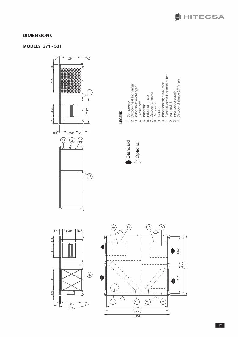
DIMENSIONS
MODELS 371 - 501
LEG
EN
D
1.
Com
pres
sor
2.
Out
door
hea
texc
hang
er3
.In
door
hea
texc
hang
er4
.E
lect
ricb
ox5
.In
door
fan
6.
Indo
orfa
nm
otor
7.
Out
door
fan
mot
or8
.O
utdo
orfa
n9
.A
irfil
ter
10.
Indo
ord
rain
age
3/4”
mal
e11
.E
xter
nalv
alve
sfo
rpr
essu
rete
st12
.M
ain
switc
h13
.In
putp
ower
sup
ply
14.
Out
door
dra
inag
e3/
4”m
ale
Stand
ard
Optional

InStAllAtIOn,.OpERAtIOn.AnD.MAIntEnAnCE.InStRUCtIOnS.-.ACHA / ACHBA
18
DIMENSIONS
MODELS 701 - 801
LEG
EN
D
1.
Ele
ctric
box
2.
Indo
orh
eate
xcha
nger
3.
Out
door
fan
mot
or4
.O
utdo
orfa
n5
.A
irfil
ter
6.
Indo
orfa
n7
.In
door
fan
mot
or8
.O
utdo
orh
eate
xcha
nger
9.
Com
pres
sor
10.
Indo
ord
rain
age
3/4”
mal
e11
.In
putp
ower
sup
ply
12.
Mai
nsw
itch
13.
Ext
erna
lval
ves
for
pres
sure
test
14.
Out
door
dra
inag
e3/
4”m
ale
Stand
ard
Optional
19
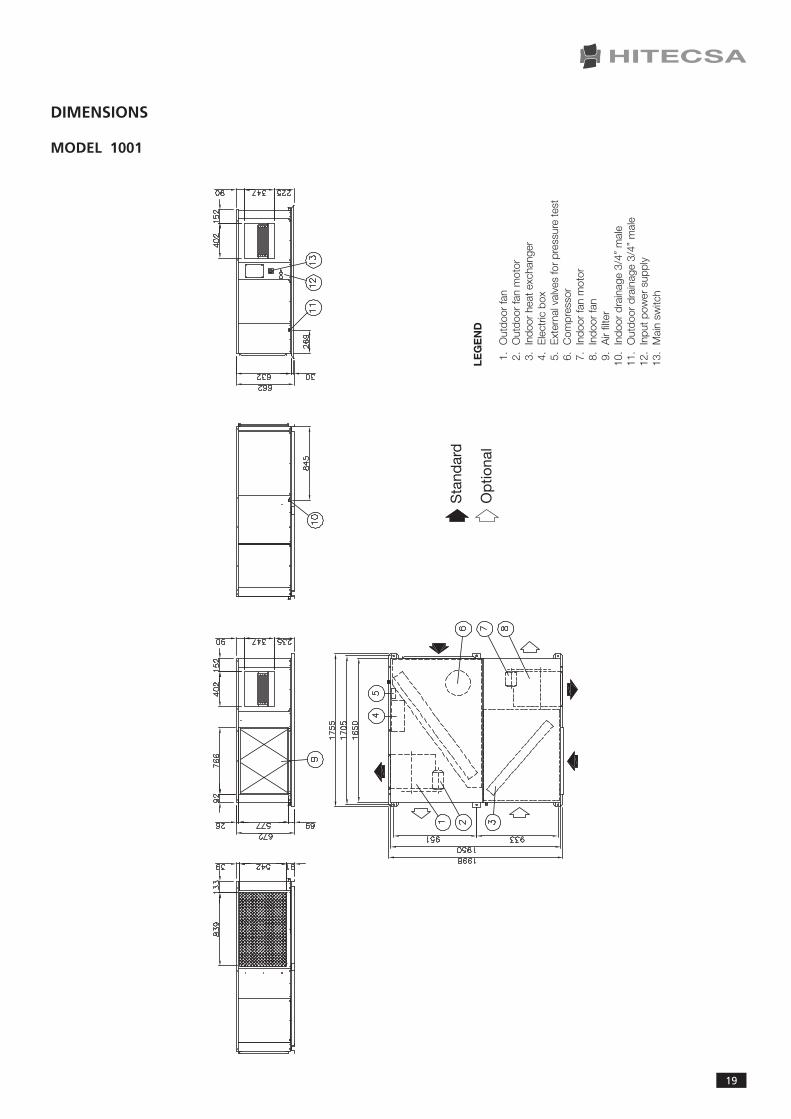
DIMENSIONS
MODEL 1001
LEG
EN
D
1.
Out
door
fan
2.
Out
door
fan
mot
or3
.In
door
hea
texc
hang
er
4.
Ele
ctric
box
5.
Ext
erna
lval
ves
for
pres
sure
test
6
.C
ompr
esso
r7
.In
door
fan
mot
or8
.In
door
fan
9.
Air
filte
r10
.In
door
dra
inag
e3/
4”m
ale
11.
Out
door
dra
inag
e3/
4”m
ale
12.
Inpu
tpow
ers
uppl
y13
.M
ain
switc
h
Stand
ard
Optional

InStAllAtIOn,.OpERAtIOn.AnD.MAIntEnAnCE.InStRUCtIOnS.-.ACHA / ACHBA
20
DIMENSIONS
MODEL 1201
LEG
EN
D
1.
Out
door
dra
inag
e3/
4”m
ale
2.
Inpu
tpow
ers
uppl
y3
.M
ain
switc
h4
.A
irfil
ter
5.
Out
door
fan
6.
Out
door
fan
mot
or
7.
Indo
orh
eate
xcha
nger
8
.In
door
fan
9.
Indo
orfa
nm
otor
10.
Com
pres
sor
11.
Out
door
hea
texc
hang
er12
.E
xter
nalv
alve
sfo
rpr
essu
rete
st
13.
Ele
ctric
box
14.
Indo
ord
rain
age
3/4”
mal
e
Stand
ard
Optional

21
8. REFRIGERANT CHARGE
•.Should.it.be.necessary.to.add.or.recover.refrigerant,.do.it.always.in.lIQUID.phase,.never.in.gas.or.vapour.phase.since.this.would.cause.wrong.mixing.conditions.
•.Due.to. its.high.pressure.and.quick.evaporation,.refrigerant.R410A.cannot.be.kept. in. liquid.phase.inside.charge.cylinder.because.bubbles.would.form,.making.reading.difficult.
•.Repair.immediately.any.refrigerant.leak.
•.never.overcharge.the.system.
•.never.use.compressor.as.a.vacuum.pump..
•. If.symptoms.of.refrigerant.loss.appear.during.operation,.it’s.necessary.to.carry.out.a.leak.test...leak.detec-tors.usually.employed.with.CFC.and.HCFC.cannot.be.used.with.R410a,.due.to.chlorine.in.its.composition...A.leak.detector.for.R134A.may.be.used.but.the.sensibility.will.be.lower.(when.sensibility.is.1.for.R134A,.it.falls.to.0,6.for.R410A)..
•.to.find.small.leaks,.you.will.need.a.detector.for.HCF..Sensibility.for.R410A.is.approx..23.grams.per.year.
•. If.a.gas.leak.is.found,.it.will.be.necessary.to.remove.and.completely.recover.the.refrigerant.charge..pressurize.the.system.with.dry.nitrogen..If.no.leakage.is.detected,.then.do.the.vacuum.and.charge.again.with.refrigerant..
WARNING!
Never use oxygen to carry out leak tests. Oxygen reacts violently when in contact with oil and could cause an explosion resulting in damage, personal
injuries or even death.
WARNING!
If it’s necessary to make welding operations, you must fill the circuit with dry nitrogen. Combustion of R410A refrigerant generates toxic gases.

InStAllAtIOn,.OpERAtIOn.AnD.MAIntEnAnCE.InStRUCtIOnS.-.ACHA / ACHBA
22
9. MAINTENANCE
It.is.advisable.to.do.maintenance.works.every.1.000.operating.hours.as.well.as.at.the.beginning.of.each.cooling.season.
•.Coils: At.least.once.a.year,.clean.condenser.coils.with.water.and.detergent,.then.dry.with.air.at.a.pressure.of.600.kpa..never.clean.with.wire.brush.
•.Fans and motors:.Adjust.transmission.belt.at.least.twice.during.the.first.month.of.operation.and.then.check.every.1.000.hours..Fan.and.motors.do.not.need.additional.lubrication.
•.Drainage system:.Verify.condition.and.good.operation.of.the.drainage.tray..Make.sure..that.holes.at.the.base.of.the.unit.are.not.blocked.so.that.evacuation.can.be.properly.done.
•.Refrigeration circuit:.Check.for.oil.refrigerant.leaks,.noises.or.system’s.vibrations..take.measurements.of.tem-peratures.and.pressures.of.components.and.record.them.on.the.maintenance.form.
•.Electrical circuit:.Make.sure.that.all.electrical.connections.-wires,.contactors,.terminals-.are.properly.tight..Re-cord.the.measurements.(volts.and.amperes).of.each.compressor.and.fan.motor..Verify.the.starting.current..Check.the.good.operation.of.all.relays,.pressostats.and.phase.sequence.relay.of.Scroll.compressor.
•.Air filters:.Clean.filters.after.the.first.4.operating.hours.and.then.every.3.months.(or.even.before)..Wash.filters.in.water.with.detergent,.rinse.thoroughly.and.let.dry.
WARNING!
Before performing any service or maintenance operation, turn off the main power switch of the system to avoid any personal injuries. Block the power switch so that
nobody other than a qualified technician can switch on electrical power.

23
10. APPENDIX: SAFETY DATA R410A
Refrigerant data Safety data: R410A
Toxicity
Contactwithskin
Contactwitheyes
Ingestion
Inhalation
Recommendations
Prolongedexposure
Professionallevels
Stability
Conditionstoavoid
Hazardousreactions
Hazardousdecompositionproducts
low
R410A.vapors.can.irritate.the.skin.and.eyes..In.liquid.form,.it.can.freeze.skin.on.contact.. If.contact.with.skin.occur,.flush. the.exposed.area.with.lukewarm.water.until.all.of.the.chemical.is.removed..If.there.is.evidence.of.frostbite,.bathe.in.lukewarm.water.
If. contact. with. eyes. occur,. immediately. flush. with. large. amounts. of..lukewarm. water. for. at. least. 15. minutes,. lifting. eyelids. occasionally. to..facilitate.irrigation..Seek.medical.attention.as.soon.as.possible.
Very. unlikely. -. should. something. happen,. it. will. cause. frost. burns.. Do.not. induce. vomiting.. Only. if. the. patient. is. conscious,. wash. out. mouth.with.water.and.give.some.250.ml.of.water.to.drink..then,.obtain.medical..attention.
Inhalation.of.the.R41.0A.vapor.may.cause.irritation..Vapor.inhalation.at.high.concentrations.may.result.in.asphyxiation.or.the.heart.may.become.sensitized,. causing. cardiac. arrhythmia.. When. concentration. of. R410A.reach.levels.which.reduce.oxygen.to.14-16%.by.displacement,.symptoms.of.asphyxiation.will.occur..An.individual.exposed.to.high.concentrations.of.R410A.must.be.given.medical.attention.immediately..Adequate.ventilation.must.be.provided.at.all.times.
Semiotics.or.support. therapy. is. recommended..Cardiac.sensitisation.has.been.observed.that,.in.the.presence.of.circulating.catecholamines.such.as.adrenalin,.may.cause.cardiac.arrhythmia.and.accordingly,.in.case.of.expo-sure.to.high.concentrations,.cardiac.arrest.
R410A: a. study. on. the. effects. of. exposure. to. 50,000. ppm. during. the.whole.life.of.rats.has.identified.the.development.of.benign.testicle.tumour..this. situation. should. therefore. be. negligible. for. personnel. exposed. to..concentrations.equal.to.or.lower.than.professional.levels.
R410A:.Recommended.threshold:.1000.ppm.v/v.-.8.hours.tWA.
R410A:..is.stable.under.normal.operating.conditions.
Do.not.use.in.the.presence.of.high.temperatures,.flames,.burning.surfaces.and.excess.humidity.
Contact.with. certain. red-hot.metals.may. result. in. exothermic.or. explo-sive. reactions. and. yield. toxic. and/or. corrosive. decomposition. products...Specific.materials.to.avoid.include.freshly.abraded.aluminum.surfaces.and.active.metals.such.as.sodium,.potassium,.calcium,.powdered.aluminum,..magnesium.and.zinc.
R410A:.Halogen.acids.produced.by.thermal.decomposition.and.hydrolysis.
InStAllAtIOn,.OpERAtIOn.AnD.MAIntEnAnCE.InStRUCtIOnS.-.ACHA / ACHBA
24
Generalprecautions
Respiratorysystemprotection
Storage
Protectiveclothing
Accidentalreleasemeasures
Disposal
Firefightinginformation
Cylinders
Protectivefirefightingequipment
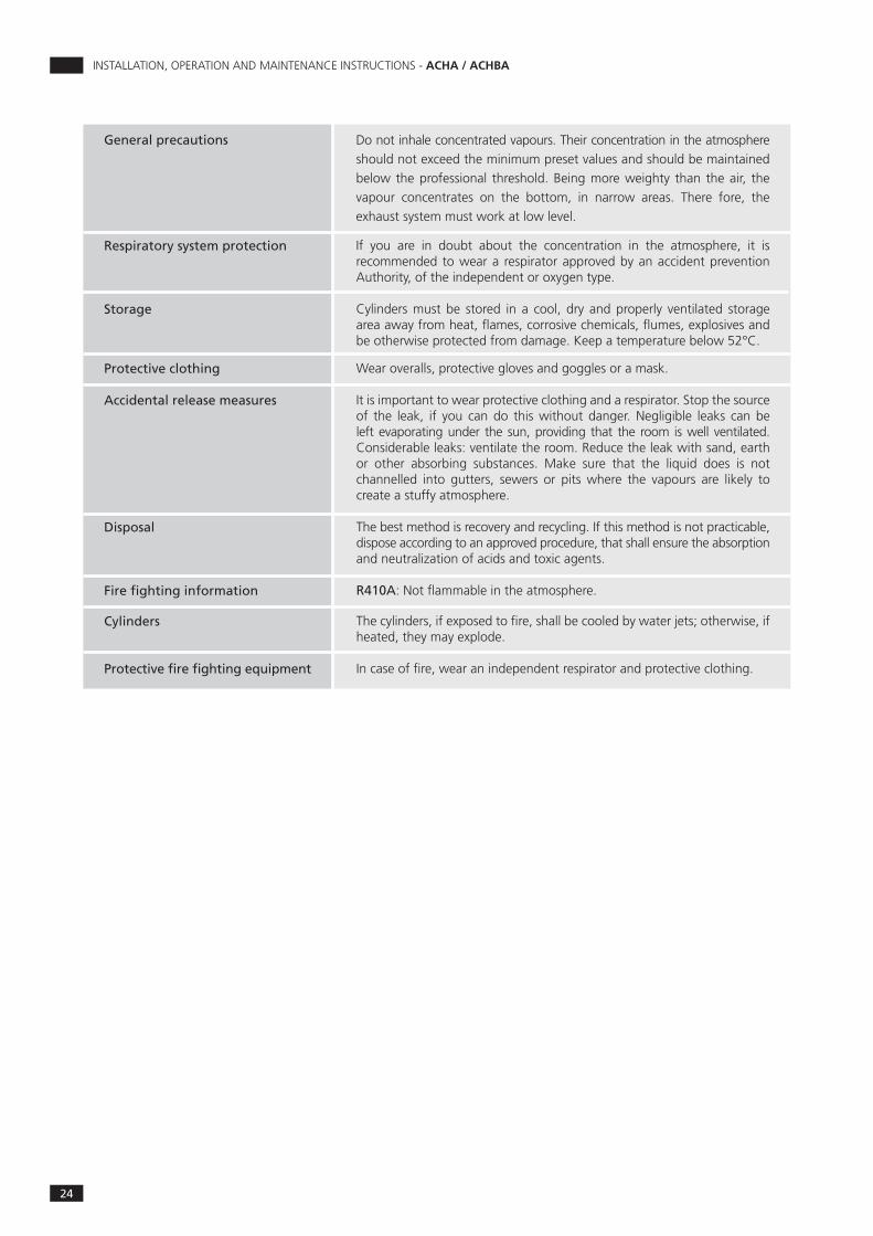
Do.not.inhale.concentrated.vapours..their.concentration.in.the.atmosphere.should.not.exceed.the.minimum.preset.values.and.should.be.maintained.below. the.professional. threshold..Being.more.weighty. than. the.air,. the.vapour. concentrates. on. the. bottom,. in. narrow. areas.. there. fore,. the..exhaust.system.must.work.at.low.level.
If. you. are. in. doubt. about. the. concentration. in. the. atmosphere,. it. is..recommended.to.wear.a. respirator.approved.by.an.accident.prevention.Authority,.of.the.independent.or.oxygen.type.
Cylinders.must.be. stored. in. a. cool,. dry. and.properly. ventilated. storage.area.away.from.heat,.flames,.corrosive.chemicals,.flumes,.explosives.and.be.otherwise.protected.from.damage..Keep.a.temperature.below.52°C.
Wear.overalls,.protective.gloves.and.goggles.or.a.mask.
It.is.important.to.wear.protective.clothing.and.a.respirator..Stop.the.source.of. the. leak,. if. you. can.do. this.without. danger..negligible. leaks. can.be.left.evaporating.under. the. sun,.providing. that. the. room. is.well. ventilated..Considerable.leaks:.ventilate.the.room..Reduce.the.leak.with.sand,.earth.or. other. absorbing. substances.. Make. sure. that. the. liquid. does. is. not..channelled. into. gutters,. sewers. or. pits. where. the. vapours. are. likely. to..create.a.stuffy.atmosphere.
the.best.method.is.recovery.and.recycling..If.this.method.is.not.practicable,.dispose.according.to.an.approved.procedure,.that.shall.ensure.the.absorption.and.neutralization.of.acids.and.toxic.agents.
R410A:.not.flammable.in.the.atmosphere.
the.cylinders,.if.exposed.to.fire,.shall.be.cooled.by.water.jets;.otherwise,.if.heated,.they.may.explode.
In.case.of.fire,.wear.an.independent.respirator.and.protective.clothing.


HITECSAAIREACONDICIONADOS.L.UnipersonalMasia.torrents,.2tel..938.934.912Fax.938.939.61508800.Vilanova.i.la.Geltrú(Barcelona,.Spain)
www.hitecsa.com
200948

CCHA/ECHA – CCHBA/ECHBA Installation, operation and maintenance instructions
1
Installation, operation and maintenance instructions
CCHA / ECHA – Cooling Only CCHBA / ECHBA – Heat Pump
SPLIT HORIZONTAL UNITS AIR-AIR

CCHA/ECHA – CCHBA/ECHBA Installation, operation and maintenance instructions
2
CONTENTS
INTRODUCTION ................................................................................ 3 SAFETY PRECAUTIONS
................................................................................
4
RECEPTION
................................................................................
5
LOCATION INSTALLATION
................................................................................
8
START UP
................................................................................
10
TECHNICAL DATA
................................................................................
14
DIMENSIONS
................................................................................
16
REFRIGERANT CHARGE
................................................................................
22
REGULATION
................................................................................
27
MAINTENANCE
................................................................................
23

CCHA/ECHA – CCHBA/ECHBA Installation, operation and maintenance instructions
3
INTRODUCTION The contents of this manual are designed to assure the correct installation, adjustment and maintenance of the unit, therefore:
• Read the instructions with due care and attention.
• The appliance must be installed, tested and serviced by properly qualified staff licensed in accordance with the established legislation.
• The manufacturer declines all liability and warranty coverage is automatically waived, if electrical and/or mechanical modifications to the unit. Tampering and unauthorized repairs or modifications to the unit will automatically void the warranty.
• Observe the safety regulations in force at the time of installation.
• Make sure that the characteristics of the mains network conform to the data on the serial number plate placed on the unit.
• Keep this manual and the wiring diagram with care and make sure that they are available for consultation by the operator whenever necessary.
• Packing materials (plastic wrappings, expanded polystyrene, etc) are potentially hazardous and must be kept out of reach of children. Recycle packing materials in accordance with local legislation.
• The units must be used only for the purpose for which they are designed. The manufacturer bears no responsibility in the case of applications other than the specified use.
• Disconnect the unit in the event of breakdowns or malfunctions.
• If repairs are necessary, use only HITECSA approved service centres and always insist on original spare parts. The use of non-original parts and/or unauthorized service centres may result in unsafe operation of the unit.
REGULATIONS AND CERTIFICATIONS ISO 9001:2008 certification: HITECSA AIRE ACONDICIONADO S.L.U., trying always to find the customer satisfaction, has obtained the ISO 9001:2008 Quality System referred to its production activity. This will result in a continuous determination to improve quality and reliability of all our products. Commercial activities, design, raw materials, production and after-sales service, are the means to reach our goal.
CE marking: our machines have got the CE mark, in conformity with the essential requirements of the applicable EC directives and their last modifications as well as with the national legislation of each country.

CCHA/ECHA – CCHBA/ECHBA Installation, operation and maintenance instructions
4
SAFETY PRECAUTIONS
• Installation and maintenance of air conditioning equipment can be dangerous because the system is under pressure, because some of its elements have high temperatures and include electrical components.
• Only qualified and trained service staff should install, commission and carry out maintenance works. Unqualified staff should only carry out basic tasks such as cleaning and replacement of filters, etc.
• In every visit, all precautions should be taken into account: those recommended in the Installation, operation and maintenance instructions, as well as the ones indicated in labels of the unit. Do not forget to strictly follow any other safety codes.
• Use safety glasses, work gloves and any other safety accessory necessary.
• For brazing operations use a quenching cloth and have at close distance a fire extinguisher.
WARNING! Before starting installation, service or maintenance, turn off the main power switch in order to
avoid electrical shock that may cause personal damages.
• When repairing the unit, use only original spare parts and install them properly in the same position where old parts were placed.
• Do not install the unit in explosive atmosphere.

CCHA/ECHA – CCHBA/ECHBA Installation, operation and maintenance instructions
5
RECEPTION INSPECTION UPON RECEIPT
• Units are delivered with special protective packing; therefore when it arrives, please inspect it carefully to check that no damage has occurred during transport and that the unit has been supplied complete with all parts specified in the order. If any damage is found, immediately file a claim with the transport company.
• Verify the correct voltage of the nameplate and make sure it’s in accordance with local power supply.
• In case of any flaw or anomaly detected, please contact HITECSA RIGGING
• Before moving the unit, make sure that all panels are well fixed.
• Raise and set down the equipment carefully.
• Do not tilt the unit more than 15 degrees during transportation. When lifting the unit, make sure that it’s balanced and stable; bear in mind that the heaviest part is where the compressor is installed.
STORAGE If the equipment is going to be stored please follow the instructions below in order to avoid damages, corrosion or deterioration:
• Keep the unit away from direct sunlight, rain, sand, wind or temperatures above 50ºC
• Storage temperature: maximum 50ºC, minimum -10ºC
• Maximum humidity: 90%

CCHA/ECHA – CCHBA/ECHBA Installation, operation and maintenance instructions
6
INSTALLATION LOCATION
• Check if the base is able to support the weight of unit during operation.
• Reserve a minimum service area according to Fig. 2.
• Choose a place free of dust or any other foreign material that could clog or damage the condenser coil. The location should also be a place that cannot be flooded.
• Consult and respect all regulations concerning installation of air conditioning systems.
• Check if sound waves do not disturb anyone and put anti-vibration plots if necessary. SERVICE AREA (mm)
CCHA/ECHA – CCHBA/ECHBA Installation, operation and maintenance instructions
7
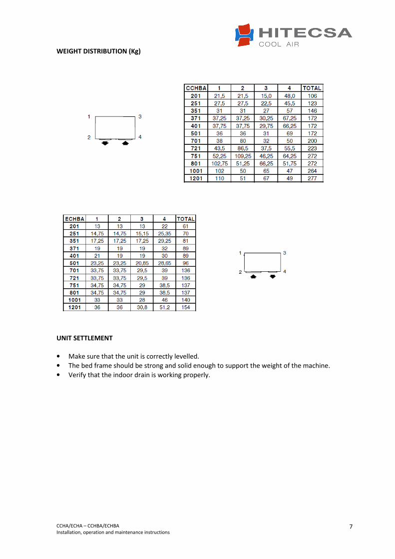
WEIGHT DISTRIBUTION (Kg)
UNIT SETTLEMENT
• Make sure that the unit is correctly levelled.
• The bed frame should be strong and solid enough to support the weight of the machine.
• Verify that the indoor drain is working properly.

CCHA/ECHA – CCHBA/ECHBA Installation, operation and maintenance instructions
8
BEFORE START UP
• Check the following points: o Wires are well tightened. o Panels are firmly secured with screws. o There are no oil or refrigerant leaks. o The unit is correctly levelled. o There is enough space for service and maintenance. o Drainage is not blocked. o Crankcase heater has been working at least 24 hours prior to the start-up. o Air filters are clean and correctly mounted. o Grilles, air diffusers, air ducts and flexible connections are in good condition. o Electrical power source is in accordance with what is said in the nameplate. o Fans rotate in the right direction.
.
START UP
• Start up should be performed by qualified technical people.
• Use a start up check list: record inlet and outlet temperatures and pressures, outdoor air temperature, volts and amps of each compressor and each fan motor, suction and discharge pressure of each compressor.
• Use a similar check list for service and maintenance works.
• Remember that after 4 hours of operation, it is necessary to clean the filters.
• Monitor at least 3 cooling cycle operations.

CCHA/ECHA – CCHBA/ECHBA Installation, operation and maintenance instructions
9
LEGEND 1. Main power 400/3/50 + neutral or 230/1 2. Earth 3. Time delay fuses or circuit breaker (MCB) curve D 4. Main power switch 5. Indoor fan motor supply 400/3** or 230.1* 6. Electric heating wiring (option) 7. Electric heating supply (option) de ∆ ∆ 400.3 or ∆ 230.1 8. Remote control OPERATING LIMITS
1 4 3
8
2
5
6
2
7 3
OUTDOOR UNIT INDOOR UNIT
Units can operate at a maximum altitude of 1.500 meters. For other conditions, please consult.

CCHA/ECHA – CCHBA/ECHBA Installation, operation and maintenance instructions
10
WARNING! Before starting installation, service or maintenance,
turn off the main power switch in order to avoid electrical shock that may cause personal damages.
• Main power supply of the unit should agree with the data shown on the nameplate. HITECSA will not be held responsible for damages resulted from non observance of the above.
• Always use the wiring diagram sent with the unit to make electrical connections.
• Make sure that the crankcase heater has been working at least 24 hours prior to the start up of the unit.
• Current supply should be within 10% of Volts and Amperes indicated on the unit nameplate.
• Do not operate the unit at different current from that shown on the unit nameplate.
• The installer should put line protection elements in compliance with current legislation.
• The interconnecting wires should be protected with a tube or put inside a groove channel. ELECTRICAL DATA
Alimentación V (50Hz) 230.I 230.I 400.III 400.III 400.III 400.III
Potencia total absorbida (1) kW 2,8 3,3 4,2 5,3 5,6 7,0
Corriente total absorbida (1) A 15 20 12 15 15 15
Potencia total absorbida (2) kW 3,5 4,1 5,3 6,9 7,1 9,23
Corriente total absorbida (2) A 16 19 13 17 17 17
Potencia total absorbida (3) kW 2,6 3,2 3,7 4,8 4,9 6,2
Corriente total absorbida (3) A 13 19 12 15 15 13
Potencia total absorbida (4) kW 3,4 4,3 4,8 5,8 6,5 8,5
Corriente total absorbida (4) A 15 19 13 16 16 15
Corriente de arranque A 63 96 43 63 63 66
Magnetotérmicos curva D * A 20 20 15 15 20 20
Sección min. cable (227 CEI 53) mm2 2,5 4,0 2,5 2,5 2,5 2,5
Alimentación V (50Hz) 400.3 400.3 400.3 400.3 400.3 400.3
Potencia total absorbida (1) kW 7,6 8,8 10,7 10,3 13,4 15,7
Corriente total absorbida (1) A 17 19 20 20 25 32
Potencia total absorbida (2) kW 10,9 12,0 13,2 13,3 17,0 20,31
Corriente total absorbida (2) A 19 21 22 22 29 34
Potencia total absorbida (3) kW 6,8 7,7 10,0 10,1 12,7 15,2
Corriente total absorbida (3) A 14 17 19 19 23 32
Potencia total absorbida (4) kW 9,4 10,2 12,4 12,0 16,4 19,46
Corriente total absorbida (4) A 18 19 21 21 27 33
Corriente de arranque A 67 96 96 96 96 158
Magnetotérmicos curva D * A 25 25 25 25 30 40
Sección min. cable (227 CEI 53) mm2 4,0 4,0 4,0 4,0 6,0 10
801 1001 1201CCHBA / ECHBA STD
CCHA / ECHA STD701 721 751
371 401CCHBA / ECHBA STD
501CCHA / ECHA STD
201 251 351
NOTES: 1.COOLING: Outdoor air temperature 35ºC. Indoor air temperature (WB) 19ºC. 2. COOLING (MAX.) : Outdoor air temperature 46ºC. Indoor air temperature (WB) 21ºC. 3.HEATING: Outdoor air temperature (WB) 6ºC. Indoor air temperature 20ºC. 4. HEATING (MAX.) : Outdoor wet temperature 18ºC. Indoor air temperature 26ºC. * Recommendation to the installer

CCHA/ECHA – CCHBA/ECHBA Installation, operation and maintenance instructions
11
DRAINAGE
• Indoor drainage (of condensate water) has a 3/4” MPT connection.
• Condensate drain line diameter should be equal or larger than the unit connection depending on pipe length and general building configuration.
• Drainage line should have a minimum inclination of 2% for proper water evacuation.
• When drainage line is exposed to temperatures below 0ºC, it is necessary to provide thermal insulation or electrical heating wire to avoid water freezing and tube damages
• It is advisable to install a trap with proper dimensions.
AIR DUCTS - Air duct dimensions will be determined according to the airflow and available static pressure. - Ducts must be designed by qualified technical people. - Use ducts made of non-inflammable materials in order to avoid any emission of gas in case of
fire. It is advisable to use metal plate duct with insulation. - Use flexible ducts to connect air ducts into the unit and thus avoid vibration and noise
transmission.

CCHA/ECHA – CCHBA/ECHBA Installation, operation and maintenance instructions
12
ADJUSTMENT OF FAN TRANSMISSION - Adjust transmission so that indoor fan-motor reaches its nominal value.. - If consumption is lower than the nominal value, the airflow is insufficient.
To change fan speed:
1. Remove the belt and slide the motor over the channel. 2. Loosen setscrews and turn the mobile flap around, depending on your needs. 3. Tight setscrews. 4. Put the belt back in the pulley’s channel. 5. Tight the belt using a tension adjuster screw.
LEGEND: 1.- Motor. 2.- Motor pulley. 3.- Belt. 4.- Fan pulley. 5.- Tensor adjustment screw. 6.- Setscrew. 7.- Mobile flap 8.- Fix flap.
7
6
8
3
1
5
4 2
Polea Pulley abiertas
Fi jo Variable Correa
kW A
CCHBA 751 X 1,5 3,6 150 E25 1A 75/100 E 24 1A A-45 0
CCHBA 801 X 1,5 3,6 150 E25 1A 100/125 E 24 1A A-45 2
CCHBA 1001 X 2,2 4,7 150 E25 1A 100/125 E 28 1A A-46 1
CCHBA 1201 X 4,0 9,2 160 E30 2A 100/125 E 28 2A A-46 2
ECHBA 501 X 0,550 1,59 150 E20 1A 100/125 E19 1A A-42 0
ECHBA 701 X 0,735 2,0 150 E25 1A 75/100 E19 1A A-43 1
ECHBA 721 X 0,735 2,0 150 E25 1A 75/100 E19 1A A-43 1
ECHBA 751 X 0,735 2,0 150 E25 1A 75/100 E19 1A A-43 1
ECHBA 801 X 0,735 2,0 150 E25 1A 75/100 E19 1A A-43 0
ECHBA 1001 X 1,5 3,0 160 E25 1A 100/125 E24 1A A-45 2
ECHBA 1201 X 2,2 4,8 160 E25 2A 100/125 E28 2A A-46 2
MODELOExterior
NominalInterior
CCHA/ECHA – CCHBA/ECHBA Installation, operation and maintenance instructions
13
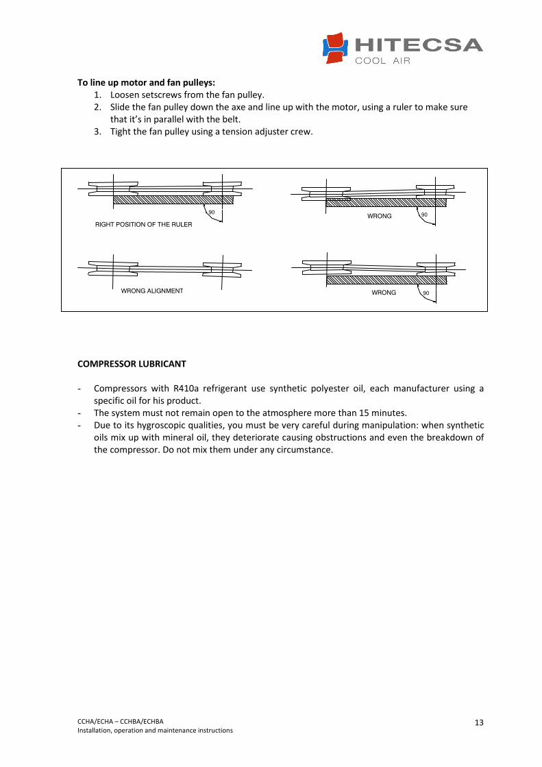
To line up motor and fan pulleys:
1. Loosen setscrews from the fan pulley. 2. Slide the fan pulley down the axe and line up with the motor, using a ruler to make sure
that it’s in parallel with the belt. 3. Tight the fan pulley using a tension adjuster crew.
COMPRESSOR LUBRICANT - Compressors with R410a refrigerant use synthetic polyester oil, each manufacturer using a
specific oil for his product. - The system must not remain open to the atmosphere more than 15 minutes. - Due to its hygroscopic qualities, you must be very careful during manipulation: when synthetic
oils mix up with mineral oil, they deteriorate causing obstructions and even the breakdown of the compressor. Do not mix them under any circumstance.
WRONG ALIGNMENT 90
°
WRONG
WRONG 90
° RIGHT POSITION OF THE RULER
90
°

CCHA/ECHA – CCHBA/ECHBA Installation, operation and maintenance instructions
14
TECHNICAL DATA
POTENCIAS
Potencia frigorífica (1) kW 5,6 7,4 9,7 11,6 12,4 14,1
Potencia calorífica (2) kW 6,1 8,2 9,8 12,0 13,8 16,4
COMPRESOR
Tipo Rotativo Rotativo Rotativo Scroll Scroll Scroll
Voltaje V 230-1 230-1 400-3 400-3 400-3 400-3
Carga de refrigerante R410A Kg 2,2 2,7 3,8 4,0 4,1 5,0
INTERCAMBIADOR INTERIOR
Tipo
Área frontal m2 0,20 0,25 0,25 0,31 0,31 0,31
Paso aletas mm 2,1 2,1 1,8 2,1 2,1 2,1
Diametro tubos " 3/8 3/8 3/8 3/8 3/8 3/8
INTERCAMBIADOR EXTERIOR
Tipo
Área frontal m2 0,22 0,292 0,36 0,4 0,4 0,4
Paso aletas mm 1,8 1,8 1,8 1,8 1,8 1,8
Diametro tubos " 3/8 3/8 3/8 3/8 3/8 3/8
VENTILADOR INTERIOR
Tipo
Modelo 9/7 DD 9/9 DD 10/10 DD 10/10 DD 10/10 DD 10/10 SS
Potencia motor kW 0,120 0,250 0,250 0,373 0,373 0,550
Voltaje V 230-1 230-1 230-1 230-1 230-1 400-3
Corriente absorbida nominal A 1,6 1,5 1,9 2,6 2,7 1,6
VENTILADOR EXTERIOR
Tipo
Modelo 9/9 DD 10/10 DD 10/10 DD 12/9 DD 12/9 DD 12/9 DD
Potencia motor kW 0,37 0,37 0,44 0,55 0,55 1,10
Voltaje V 230-1 230-1 230-1 230-1 230-1 400-3
Corriente absorbida nominal A 4,0 4,0 4,3 4,8 4,7 3,0
501
Batería de aletas de aluminio y tubos de cobre
Batería de aletas de aluminio y tubos de cobre
Centrífugo de doble aspiración
Centrífugo de doble aspiración
CCHA / ECHA 201 371251 351 401
CCHBA / ECHBA
(1) COOLING: Outdoor air temperature: 35 °C. Indoor air temperature (WB): 19 °C. (2) HEATING: Outdoor air temperature (WB).: 6 °C. Indoor air temperature: 20 °C.

CCHA/ECHA – CCHBA/ECHBA Installation, operation and maintenance instructions
15
TECHNICAL DATA
POTENCIAS
Potencia frigorífica (1) kW 17,2 18,5 20,8 21,9 28,4 33,5
Potencia calorífica (2) kW 18,9 20,4 21,9 24,6 29,8 37,2
COMPRESOR
Tipo
Voltaje V 400-3 400-3 400-3 400-3 400-3 400-3
Carga de refrigerante R410A Kg 5,7 5,7 5,9 6,7 9,0 9,5
INTERCAMBIADOR INTERIOR
Tipo
Área frontal m2 0,47 0,47 0,47 0,54 0,65 0,77
Paso aletas mm 1,8 1,8 1,8 1,8 1,8 1,8
Diametro tubos " 3/8 3/8 3/8 3/8 3/8 3/8
INTERCAMBIADOR EXTERIOR
Tipo
Área frontal m2 0,605 0,605 0,605 0,605 0,9 1,19
Paso aletas mm 1,8 1,8 1,8 1,8 1,8 1,8
Diametro tubos " 3/8 3/8 3/8 3/8 3/8 3/8
VENTILADOR INTERIOR
Tipo
Modelo 12/9 SS 12/9 SS 12/9 SS 12/9 SS 12/12 SS 15/15 SS
Potencia motor kW 0,735 0,735 0,735 0,735 1,500 2,200
Voltaje V 400-3 400-3 400-3 400-3 400-3 400-3
Corriente absorbida nominal A 2,0 2,0 2,1 2,3 3,0 4,8
VENTILADOR EXTERIOR
Tipo
Modelo 12/12 DD 12/12 DD 12/12 SS 12/12 SS 12/12 SS 15/15 SS
Potencia motor kW 1,10 1,10 1,50 1,50 2,20 4,00
Voltaje V 400-3 400-3 400-3 400-3 400-3 400-3
Corriente absorbida nominal A 3,5 3,5 3,4 3,6 4,7 9,2
1201
Batería de aletas de aluminio y tubos de cobre
Batería de aletas de aluminio y tubos de cobre
Scroll
Centrífugo de doble aspiración
Centrífugo de doble aspiración
CCHA / ECHA 701 801721 751 1001
CCHBA / ECHBA
(1) COOLING: Outdoor air temperature: 35 °C. Indoor air temperature (WB): 19 °C. (2) HEATING: Outdoor air temperature (WB).: 6 °C. Indoor air temperature: 20 °C.

CCHA/ECHA – CCHBA/ECHBA Installation, operation and maintenance instructions
16
DIMENSIONS CCHA – CCHBA 351
ECHA – ECHBA 351

CCHA/ECHA – CCHBA/ECHBA Installation, operation and maintenance instructions
17
CCHA – CCHBA 371 – 401 – 501
ECHA – ECHBA 371 – 401 – 501

CCHA/ECHA – CCHBA/ECHBA Installation, operation and maintenance instructions
18
CCHA – CCHBA 701 – 721 – 751 - 801
ECHA – ECHBA 701 – 721 – 751 - 801

CCHA/ECHA – CCHBA/ECHBA Installation, operation and maintenance instructions
19
REFRIGERANT LINES
REFRIGERANT CIRCUIT Split systems demand a correct disposition of refrigerant piping and a correct connection between both indoor and outdoor units. Line selection should be done according to the following criteria: - Pressure drop of the line - Circulation speed of the refrigerant - Refrigerant mass DISCHARGE LINE In heat pump operation, the gas line works as discharge line.
WARNING!!! When working with the machines in operation, discharge line temperature is very HIGH and
could result in burns.
TRAZADO DE LÍNEAS 1. When indoor unit is at a lower level than outdoor unit: It is not essential to install traps in the
vertical line. However, it could be convenient to install some every 6 to 9 meters in order to help oil return.
A – INDOOR UNIT
B – OUTDOOR UNIT
GAS LINE
LIQUID LINE
B
A

CCHA/ECHA – CCHBA/ECHBA Installation, operation and maintenance instructions
20
2. When indoor unit is at the same level as outdoor unit: rise the suction line to a higher level
than the exchanger in order to avoid refrigerant return into the compressor.
3. When indoor unit is at a higher level than outdoor unit.
LÍNEA DE GAS
LÍNEA DE LÍQUIDO
A B
A – UNIDAD INTERIOR
B – UNIDAD EXTERIOR
LÍNEA DE GAS
LÍNEA DE LÍQUIDO
LÍNEA DE GAS
LÍNEA DE LÍQUIDO LÍNEA DE LÍQUIDO
A B
A – UNIDAD INTERIOR
B – UNIDAD EXTERIOR
A B
A – UNIDAD INTERIOR
B – UNIDAD EXTERIOR
A – UNIDAD INTERIOR
B – UNIDAD EXTERIOR
B
A
LÍNEA DE GAS
LÍNEA DE LÍQUIDO
A – UNIDAD INTERIOR
B – UNIDAD EXTERIOR
B
A
B
A
LÍNEA DE GAS
LÍNEA DE LÍQUIDO
LÍNEA DE GAS
LÍNEA DE LÍQUIDO LÍNEA DE LÍQUIDO
A – UNIDAD INTERIOR
B – UNIDAD EXTERIOR
A – UNIDAD INTERIOR
B – UNIDAD EXTERIOR

CCHA/ECHA – CCHBA/ECHBA Installation, operation and maintenance instructions
21
NOTES :
- Refrigerant lines should be as short and straight as possible. Use recommended diameters to reduce quantity of refrigerant in the system.
- Fasten the tubes to fixed elements by means of braces to avoid vibration. - Carry out welding works in dry nitrogen atmosphere inside the line to be welded -USE A
BOTTLE WITH PRESSURE REGULATOR- to avoid the appearance of oxide and to expel rest of polluting material or humidity. Use rods with a minimum 15% of silver alloy.
- Insulate suction line in order to avoid condensation. Liquid line will be insulated only when exposed to high temperatures (solar radiation, etc.)
- Horizontal segment of suction line: 4% pitch towards the compressor. - In addition to refrigerant, sometimes it’s necessary to add oil. For more than 25 meters,
add 30 grams. - When height difference is more than 30 meters, it may be necessary to install an oil
separator on discharge line. - If liquid line is descendant and there is a considerable height difference, you have to
compensate the excess pressure before the expansion. - If liquid line is ascendant and there is a considerable height difference, the formation of gas
refrigerant before the expansion must be avoided. - If you should not find the chosen pipe diameter, you can use the immediately lower
diameter. The system will function normally only with a slight reduction of performance.

CCHA/ECHA – CCHBA/ECHBA Installation, operation and maintenance instructions
22
REFRIGERANT CHARGE
WARNING!!! It is forbidden by law to expel refrigerant into the atmosphere; therefore, it is necessary to
recover all the refrigerant and to avoid leaks.
- Units CCHA-CCHBA y ECHA-ECHBA are supplied with nitrogen charge. Before proceeding to any welding work, it’s necessary to remove this charge out of the interconnection lines. Once you have finished, make the vacuum and charge with the right amount of refrigerant.
WARNING!!! Never use oxygen to carry out leak tests. Oxygen reacts violently when in contact with oil and
could cause an explosion resulting in damage, personal injuries or even death.
• Should it be necessary to add or recover refrigerant, do it always in LIQUID phase, never in gas
or vapour phase since this would cause wrong mixing conditions.
• Due to its high pressure and quick evaporation, refrigerant R410A cannot be kept in liquid phase inside charge cylinder because bubbles would form, making reading difficult.
WARNING!!! If it’s necessary to make welding operations, you must fill the circuit with dry nitrogen.
Combustion of R410a refrigerant generates toxic gases.
• Repair immediately any refrigerant leak.
• Never overcharge the system.
• Never use compressor as a vacuum pump.
• If symptoms of refrigerant loss appear during operation, it’s necessary to carry out a leak test. Leak detectors usually employed with CFC and HCFC cannot be used with R410a, due to chlorine in its composition. A leak detector for R134a may be used but the sensibility will be lower (when sensibility is 1 for R134a, it falls to 0,6 for R410a).
• To find small leaks, you will need a detector for HCF. Sensibility for R410A is approx. 23 grams per year.
• If a gas leak is found, it will be necessary to remove and completely recover the refrigerant charge. Pressurize the system with dry nitrogen. If no leakage is detected, then do the vacuum and charge again with refrigerant.

CCHA/ECHA – CCHBA/ECHBA Installation, operation and maintenance instructions
23
MAINTENANCE
WARNING!!! Before performing any service or maintenance operation, turn off the main power switch of the
system to avoid any personal injuries. Block the power switch so that nobody other than a qualified technician can switch on electrical power.
• It is advisable to do maintenance works every 1.000 operating hours as well as at the beginning of each cooling season.
• Coils: at least once a year, clean condenser coils with water and detergent, then dry with air at a pressure of 600 kPa. Never clean with wire brush.
• Fans and motors: adjust transmission belt at least twice during the first month of operation and then check every 1.000 hours. Fan and motors do not need additional lubrication.
• Drainage system: verify condition and good operation of the drainage tray. Make sure that holes at the base of the unit are not blocked so that evacuation can be properly done.
• Refrigeration circuit: check for oil refrigerant leaks, noises or system’s vibrations. Take measurements of temperatures and pressures of components and record them on the maintenance form.
• Electrical circuit: make sure that all electrical connections -wires, contactors, terminals- are properly tight. Record the measurements (volts and amperes) of each compressor and fan motor. Verify the starting current. Check the good operation of all relays, pressostats and phase sequence relay of Scroll compressor.
• Air filters: clean filters after the first 4 operating hours and then every 3 months (or even before). Wash filters in water with detergent, rinse thoroughly and let dry.

CCHA/ECHA – CCHBA/ECHBA Installation, operation and maintenance instructions
24
www.hitecsa.com HITECSA AIRE ACONDICIONADO S.L.U. Masia Torrents, 2 08800 Vilanova i la Geltrú (Barcelona) España Tel. +34 93 893 49 12 Fax. +34 93 893 96 15 [email protected]