achieving success in the commissioning and startup of
TRANSCRIPT

Implementation Resource 312-2
Volume II
Achieving Success in the Commissioning and Startup of Capital Projects: Mini-Case Studies
CII Member Companies
AbbottAmeren CorporationAmerican Transmission CompanyAnadarko Petroleum CorporationAnglo AmericanAnheuser-Busch InBevAramco Services CompanyArcelorMittalArchitect of the CapitolAstraZenecaBG GroupBP AmericaCargillChevronConocoPhillipsConsolidated Edison Company of New YorkDTE EnergyThe Dow Chemical CompanyDuPontEastman Chemical CompanyEcopetrolEnbridgeEnLink MidstreamEskom Holdings SOCExxonMobil CorporationGeneral Electric CompanyGeneral Motors CompanyGlaxoSmithKlineGlobal Infrastructure PartnersHoneywell InternationalHuntsman CorporationIntel CorporationIrving Oil LimitedKaiser PermanenteKoch IndustriesEli Lilly and CompanyLyondellBasellMarathon Petroleum CorporationNational Aeronautics & Space AdministrationNOVA Chemicals CorporationONEOKOccidental Petroleum CorporationOntario Power GenerationPacific Gas and Electric CompanyPetroleo Brasileiro S/A - PetrobrasPetroleos MexicanosPetronasPhillips 66Pioneer Natural ResourcesPraxairThe Procter & Gamble CompanyPublic Service Electric & Gas CompanyReliance Industries Limited (RIL)SABIC - Saudi Basic Industries CorporationSasol Technology Proprietary LimitedShell Global Solutions USSmithsonian InstitutionSouthern CompanyStatoil ASASunCoke EnergyTennessee Valley AuthorityTransCanada CorporationU.S. Army Corps of EngineersU.S. Department of Commerce/NIST/
Engineering LaboratoryU.S. Department of Defense/
Tricare Management ActivityU.S. Department of EnergyU.S. Department of StateU.S. Department of Veterans AffairsU.S. General Services AdministrationThe Williams Companies
AECOMAMEC Foster WheelerAZCOAecon GroupAffiliated Construction ServicesAlstom PowerAtlas RFID SolutionsAutodeskBaker Concrete ConstructionBarton Malow CompanyBechtel GroupBentley SystemsBilfinger Industrial ServicesBlack & VeatchBurns & McDonnellCB&ICCC GroupCDI Engineering SolutionsCH2MCSA CentralConstrutora Norberto OdebrechtCoreworx Day & ZimmermannEmerson Process ManagementEnstoaFaithful+GouldFluor CorporationHargrove Engineers + ConstructorsHilti CorporationIHI E&C International CorporationIHSInternational Rivers ConsultingJMJ AssociatesJV Driver ProjectsJacobsKBRKiewit CorporationLauren Engineers & ConstructorsLeidos Constructors Matrix Service CompanyMcCarthy Building Companies McDermott InternationalMidwest SteelPCL Construction Enterprises PTAGParsonsPathfinderQuality Execution Richard Industrial GroupThe Robins & Morton GroupS & B Engineers and ConstructorsSBM OffshoreSNC-LavalinSkanska USASupreme GroupTechnipTOYO-SETAL EngenhariaUniversalPegasus InternationalVictaulicWESCO InternationalWalbridgeWanzek ConstructionThe Weitz CompanyWilhelm Construction Wood Group MustangWorleyParsonsYates ConstructionZachry GroupZurich
Achieving Success in the Commissioning and Startup of Capital Projects: Mini-Case Studies
Research Team 312, Best Practices for Commissioning and Startup
Construction Industry Institute
Implementation Resource 312-2, Volume II
September 2015
© 2015 Construction Industry Institute™
The University of Texas at Austin
CII members may reproduce and distribute this work internally in any medium at no cost to internal recipients. CII members are permitted to revise and adapt this work for their internal use, provided an informational copy is furnished to CII.
Available to non-members by purchase; however, no copies may be made or distributed, and no modifications may be made without prior written permission from CII. Contact CII at http://construction-institute.org/catalog.htm to purchase copies. Volume discounts may be available.
All CII members, current students, and faculty at a college or university are eligible to purchase CII products at member prices. Faculty and students at a college or university may reproduce and distribute this work without modification for educational use.
Printed in the United States of America.

iii
Contents
1
19
25
Case Study A Plant X Energy Center
Case Study B Urban Water Pumping Station
Case Study C Project Y Downstream Chemical Plant
Case Study D 31Power Generating Facility: Selective Catalytic Reduction
Ammonia Unit Forwarding Line


1
Case Study A
Plant X Energy Center
Project Description
One day in 2012, the boiler feed pump turbine at the Plant X Energy Center Unit (a coal-fired steam plant) experienced an uncontrolled overspeed event, resulting in significant damage to the turbine and surrounding equipment. The unit had been brought on line with the motor-driven boiler feed pump at 1:30 a.m. and was operating at about 200 megawatts. The plant's two steam-driven boiler feed pumps had been uncoupled from their turbines for the normally scheduled overspeed testing. The tuning of the boiler feed pump turbine steam control and stop valves had not been completed, and the boiler feed pump steam stop valves were in the open position. Shortly after 9:00 a.m., the boiler feed pump turbine steam control valves drifted open without any operator-initiated control signal command calling for them to open. Since the steam stop valves were upstream of the control valves and in the open position, the main steam immediately drove the boiler feed pump turbine speed to greater than 9,000 revolutions per minute (RPMs). Normal maximum running speed is approximately 5,600 RPMs, and the overspeed protection trip point is set at approximately 6,000 RPMs. Last stage blades were thrown from the boiler feed pump turbine due to this overspeed event. The boiler feed pump suction line was punctured by one of the thrown blades, releasing great amounts of water in the area. Another thrown blade severed a group of power and control cables above the boiler feed pump turbine, pieces of turbine blades were thrown through the turbine room roof, and other piping was damaged, including the main turbine main steam piping. All personnel were safely evacuated and accounted for, and no one suffered any injuries.
Project and CSU-related Performance or Outcome
The boiler feed pump turbine was uncoupled from the pump and put in a reset condition, ready for tuning/testing of newly installed distributed control system (DCS) controls. In the reset condition, the boiler feed pump turbine’s steam stop valves were open, and the downstream steam control valves were closed. The steam control valves suddenly went full open and failed to respond to DCS-initiated close signals, causing uncontrolled acceleration of the boiler feed pump turbine. The protective devices failed to trip the boiler feed pump turbine quickly enough, allowing it to overspeed. The boiler
2
Plant X Energy Center
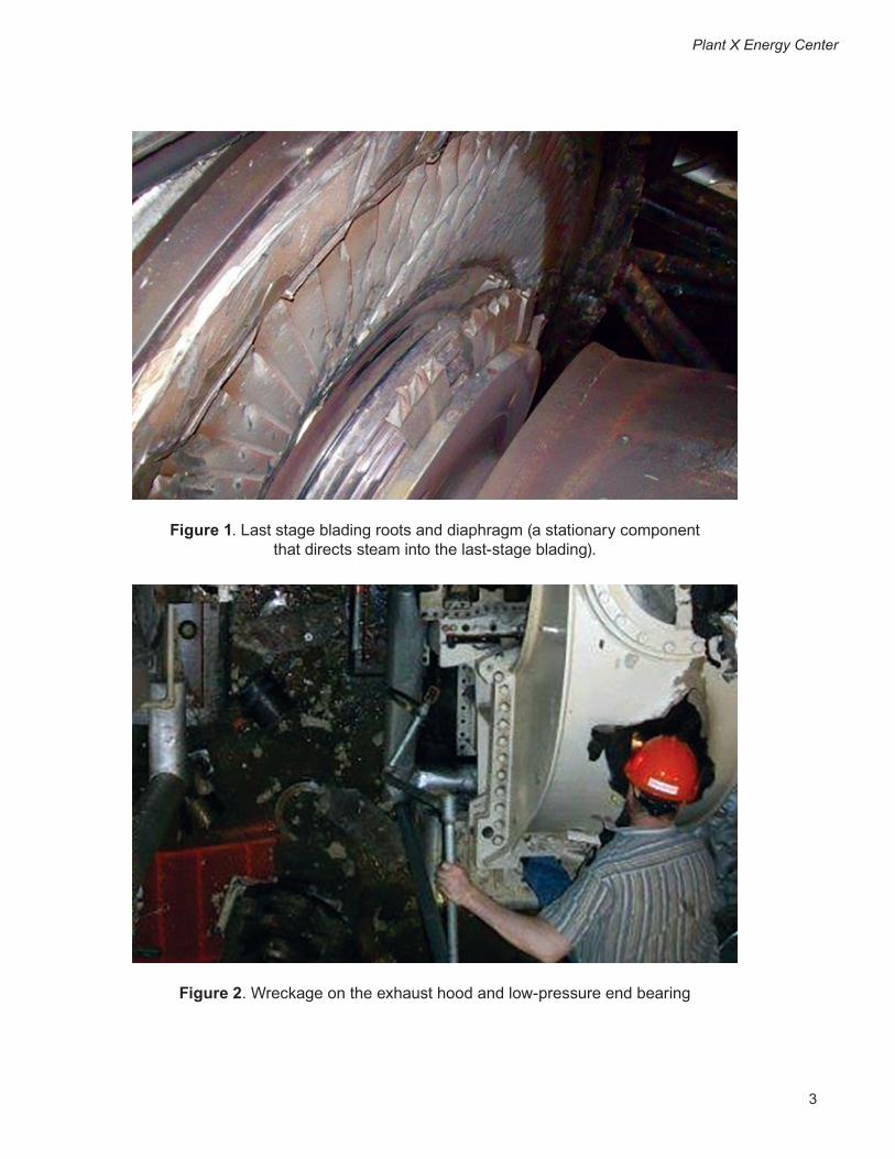
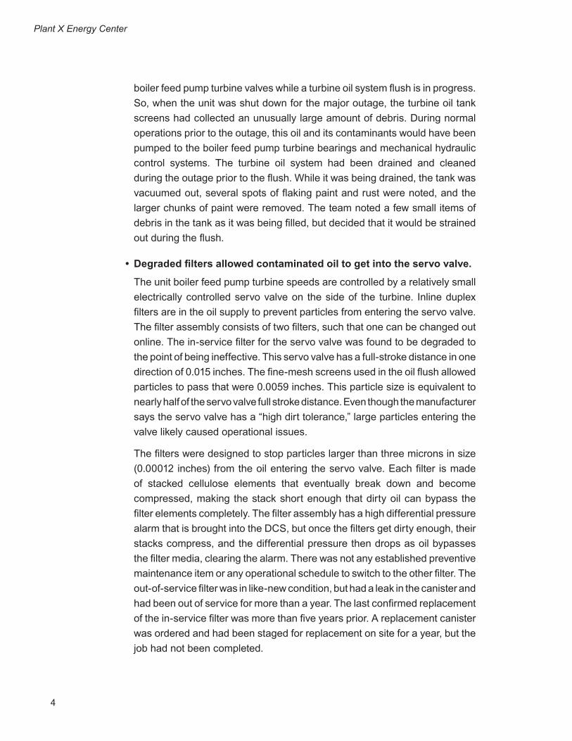
feed pump turbine accelerated past its design speed of 5,600 RPMs, resulting in failure. Then, the last stage blading of the boiler feed pump turbine was ejected through the casing, damaging nearby piping and electrical cable trays. (Figures 1 and 2 show some of the damage.) Finally, a fire erupted at the high-pressure end of the boiler feed pump turbine, as the shaft grounding device broke and discharged oil onto nearby hot steam valves. The fire was extinguished by the plant’s deluge fire protection system and the water that had been released as a result of collateral damage to the boiler feed pump suction line; this line emptied the entire deaerating heater storage tank contents (approximately 60,000 gallons of 300°F water) onto the failed boiler feed pump turbine. The plant was evacuated, all personnel were accounted for, and the unit was removed from service for repairs. After the event was contained, two major questions remained: 1) What caused the uncontrolled acceleration?; and 2) Why did the boiler feed pump turbine fail to trip?
CSU-related Problems, Opportunities, and Contributing Factors
Possible causal factors of the uncontrolled acceleration of the boiler feed pump turbine
• Oil contamination was present in the turbine oil system.
The turbine oil tank collects oil that has flowed through all the bearings of the main turbine and boiler feed pump turbines. Pumps mounted on the turbine oil tank work to pump the oil back to the bearings and to the hydraulic controls of the boiler feed pump turbines. During the outage that preceded this event, the project to replace the boiler feed pump turbine controls required use of the oil system for checkout and testing of the newly installed controls. At the same time, an oil system flush was in progress due to the extensive main turbine work that had been completed. The original equipment manufacturer (OEM) recommends an oil system flush be performed following major turbine work to ensure that dirt and foreign material are removed from the oil prior to operation of the main turbine. Since part of the flush involved filtering the return oil to the tank, the project team installed fine-mesh screens over the normal turbine oil tank screen panels inside the turbine oil tank. As the oil was flushed through the piping, debris and contaminants were rinsed back to the tank. The fine-mesh screens stopped the larger debris, but since the screen has an actual opening size of 0.0059 inches, particles of 150 microns or smaller easily passed through the screen. Even though the team used standard methods to conduct the oil flush, it is not normal practice to stroke
3
Plant X Energy Center
Figure 1. Last stage blading roots and diaphragm (a stationary component that directs steam into the last-stage blading).
Figure 2. Wreckage on the exhaust hood and low-pressure end bearing
4
Plant X Energy Center
boiler feed pump turbine valves while a turbine oil system flush is in progress. So, when the unit was shut down for the major outage, the turbine oil tank screens had collected an unusually large amount of debris. During normal operations prior to the outage, this oil and its contaminants would have been pumped to the boiler feed pump turbine bearings and mechanical hydraulic control systems. The turbine oil system had been drained and cleaned during the outage prior to the flush. While it was being drained, the tank was vacuumed out, several spots of flaking paint and rust were noted, and the larger chunks of paint were removed. The team noted a few small items of debris in the tank as it was being filled, but decided that it would be strained out during the flush.
• Degraded filters allowed contaminated oil to get into the servo valve.
The unit boiler feed pump turbine speeds are controlled by a relatively small electrically controlled servo valve on the side of the turbine. Inline duplex filters are in the oil supply to prevent particles from entering the servo valve. The filter assembly consists of two filters, such that one can be changed out online. The in-service filter for the servo valve was found to be degraded to the point of being ineffective. This servo valve has a full-stroke distance in one direction of 0.015 inches. The fine-mesh screens used in the oil flush allowed particles to pass that were 0.0059 inches. This particle size is equivalent to nearly half of the servo valve full stroke distance. Even though the manufacturer says the servo valve has a “high dirt tolerance,” large particles entering the valve likely caused operational issues.
The filters were designed to stop particles larger than three microns in size (0.00012 inches) from the oil entering the servo valve. Each filter is made of stacked cellulose elements that eventually break down and become compressed, making the stack short enough that dirty oil can bypass the filter elements completely. The filter assembly has a high differential pressure alarm that is brought into the DCS, but once the filters get dirty enough, their stacks compress, and the differential pressure then drops as oil bypasses the filter media, clearing the alarm. There was not any established preventive maintenance item or any operational schedule to switch to the other filter. The out-of-service filter was in like-new condition, but had a leak in the canister and had been out of service for more than a year. The last confirmed replacement of the in-service filter was more than five years prior. A replacement canister was ordered and had been staged for replacement on site for a year, but the job had not been completed.

5
Plant X Energy Center
• The servo valve was operating under extreme cycling conditions.
The servo valve normally makes very small movements to port oil to the bottom of the pilot valve. The pilot valve operates against spring pressure to port oil either to or from the operating cylinder, which is directly linked to the turbine’s control valves. The servo valve has to port enough oil to get the much larger pilot valve lifted quickly into its null position (where it is neither porting oil to or from the operating cylinder), and then move the right amount to control the speed of the turbine. The controls that drive the servo valve motor were changed during the outage, so the servo valve needed to be re-tuned to its new control loop. In the hours leading up to the event, the servo valve was rapidly cycling due to incomplete tuning. Tuning of this valve may have been impossible due to the build-up of contaminants found in the servo valve body after the event. Trend data of the pilot valve position showed that the pilot valve movement (normally less than one percent of full travel) was rapidly swinging more than 15 percent, up to 20 times a minute. This movement was cycling oil to and from the operating cylinder, but not for a long enough duration each cycle to cause the steam control valves to open.
Four hours before the overspeed event, the controls tuner sensed the extreme cycling of the servo valve and detuned it. This reduced the swings of the pilot valve from 15 percent back to one percent, but this was still an extreme amount of movement, and it was still swinging three to four cycles per minute. The servo valve failed by sticking in one position, allowing pressure to continue to build under the pilot valve, porting it open, and causing the steam control valves to open. After the event, the servo valve was removed from the turbine, and was found to have sloppy movement and sticky spots in its travel. These sticky spots were severe enough that the valve would fail to respond to control signals attempting to drive the servo valve back to its rest position. Later, at a servo valve repair facility, the valve was disassembled and found to have sludge and contaminant build-up in the valve ports. It is suspected that the extreme cycling of the servo valve, along with dirty oil, accelerated the wear on it. Since there were no indications of operational issues with the servo valve before the outage, it was not replaced during the outage. Before the event, the servo was rapidly oscillating, which would normally have been enough to cause the steam control valves to oscillate too. Post-event trend data does not support this expectation. There was no evidence available that the DCS initiated the event.
6
Plant X Energy Center
Possible Causal Factors of the Events Leading to Failure to Trip
• Debris and foreign material were found in the trip valve/reset piston assembly.
Much debris and grit was found in the cylinders of the mechanical hydraulic trip system, and there were several possible contributors to this accumulation. Most notable was the failed rubber boot that was designed to provide a seal on the trip valve/reset piston indication rod that penetrates the top of the trip reset assembly at the turbine front standard. This boot was in very poor condition and allowed debris to enter the cylinder. The O-ring that seals the top portion of the trip reset assembly to the front standard top cover was missing. All of these missing seals provided an entry route for dirt and debris. None of the pistons in the trip reset assembly could be verified for proper operation after the incident, since they suffered damage during the event. Trend data collected after the event showed that the trip assembly was taking longer to trip each time it was tripped. Before the outage, the time from initiation of an electronic trip to the time the steam stop valves indicated that they were closed about one second. The first time a trip was initiated (near the completion of the outage), it took two seconds. Subsequent trips took four seconds, then five seconds, and then nine seconds. During the failure event, it took 12 seconds from initiation of trip signal to steam stop valve closure. The trip valve may have dumped oil only after being affected by the turbine rotor during the failure. Repeated operation during testing with contaminated oil likely increased the trip times.
• Inoperable mechanical overspeed trip governor
When the turbine was disassembled after the overspeed event, the condition of the overspeed governor was examined. It was found to be non-functional, and showed no evidence of being actuated (extended) during the overspeed event. The construction of the governor comprises a spring-loaded brass plunger with a continuous shaft through the device housing. The plunger could not be moved by applying normal pressure to the end of the shaft. Once it had been freed, it became stuck in the trip position (extended). It is believed that, if it had been actuated during the event, it would have been found in the extended position due to this stickiness. The housing for the governor was damaged during the event, so it is possible that its operation was altered by the event itself. The data from the previous year’s overspeed tests indicated that actual overspeed trips were increasing instead of decreasing. According to OEM, a sticking plunger usually frees up with use, and subsequent trips occur at lower RPMs. This observation is validated by the earlier data. The overspeed governor acts on the same trip finger that is acted on by the manual trip handle and the trip

7
Plant X Energy Center
piston, which is used for electrical trips through a solenoid. In this case, since a trip was already in progress from the DCS, the trip finger would have already unlatched the trip valve/reset piston. This assumes that the trip piston functioned (even if it was sluggish), but this could not be verified. Based on the amount of sludge in the cylinders, it is likely that the trip piston did function, and that the trip valve reset piston assembly was sluggish. If that were the case, the trip finger would already have been rotated out of the way, and the overspeed governor would not have had anything on which to act.
Possible Failed Defenses:
• Personnel had generally low levels of knowledge and understanding of the boiler feed pump turbine controls.
Plant management, operations, engineering, and maintenance employees were found to have a low level of knowledge regarding the set-up and interface of the boiler feed pump turbine control system. This lack of understanding was itself a failed defense, having limited the staff’s ability to make informed risk decisions regarding the other failed defenses during the event. This failed defense applied to some degree, either directly or indirectly, at all levels of the plant organization.
• Not having established any documented preventive maintenance basis for the boiler feed pump turbines led to the following:
– Deficient operational checks: The daily and weekly operations activities recommended by the manufacturer were not performed regularly or recorded. These activities are designed to keep the mechanical hydraulic trip system exercised and to provide an early warning of any underlying problems with the overall protective scheme that would not otherwise be indicated. No process (e.g., check-sheet or log record) existed to incorporate these activities into operational routines. One of the factors in the event was equipment cleanliness. The compromised boot and the missing O-ring allowed dirt to enter the system. In addition, the build-up of dirt on the top of the front standard should not have been present. There were oil-soaked wipes present at the bottom of the control console cabinet, and grime build-up in locations at which leaked oil had mixed with dust from coal and fly ash leaks in the building.
– Deficient equipment maintenance: The in-service filter for the servo valve was in failed condition. Periodic replacement or inspection needed to be performed. No preventive maintenance had been established for the filters.
8
Plant X Energy Center
• Inadequate oversight of instrumentation tuner during controls checkout phase
This is not directly related to the event, but it addresses questions posed by employees regarding the sequence of events and the testing in progress. On the morning of the event, the controls field engineer reloaded the DCS control, which controls the boiler feed pump turbines. Due to excessive overshoot in the pilot valve control loop, the boiler feed pump turbine unexpectedly started rolling. The field engineer loaded the control drop without the consent of the operations staff and in the absence of the owner’s test personnel in the computer room. Since the turbine was in “auto” mode, the DCS controls initiated a trip as soon as the turbine speed reached 1,000 RPMs above set speed; but, the steam stop valves did not close until 24 seconds later. The turbine was out of control, turning at a speed that went above the 100-percent rated speed (5,600 RPMs), peaking at 5,726 RPMs.
• Inadequate communication between commissioning team members
In a post-event interview, the computer technician who tested the boiler feed pump turbine controls said that, when he left on the evening before the event, he thought no further tuning or testing was required with the steam valved in. Turnover from the controls tuner to the project engineer on the evening before the event indicated that, although there was more work to do, it would be possible to get the overspeeds performed. The project engineer was unaware of the computer technician’s opinion of the readiness of the boiler feed pump turbine controls.
• Inadequate mechanical engineering experience involved with the controls replacement project
Although the designer of the project’s DCS controls strongly recommended having a mechanical engineer on site to assist with the calibration of the servo and pilot valves, this advice was not taken. A few factors influenced that decision: the station’s computer technicians had previous experience calibrating the servo valves; no mechanical components were to be replaced; and the project had no mechanical engineering support from either the plant staff or corporate resources. Hoerver, having a greater depth of mechanical engineering experience involved in the servo valve tuning would have been beneficial.
9
Plant X Energy Center
• Lack of clear procedures during checkout and testing of new controls
The project had neither clearly identified a commissioning plan for the new controls, nor had it developed any operational procedures for the new boiler feed pump turbine controls, including trip-checks and overspeed testing.
• Outage schedule pressure
The time available in the outage schedule to perform checkout of the controls lessened as the outage progressed. Originally, the schedule had allotted eight days after the turbine oil flush to complete the testing and checkout of the new boiler feed pump turbine controls. The thinking was that the testing and checkout would require only two days. Additional work scope on the main low pressure turbine replacements caused an 11-day delay in getting the turbine oil system restored; this, in turn, delayed the testing of the boiler feed pump controls. Moving the outage end date up two days, due to early completion of critical-path work, added even more pressure to the schedule. The time allotted for testing was compressed into the two days that were believed to be needed. The turbine oil system flush and boiler feed pump turbine valve testing were allowed to be performed concurrently without objection.
• Fatigued testing personnel
The project engineer responsible for the project worked 60 hours in the four days leading up to the event. By the time he left the plant site after attempting to run the boiler feed pump turbine early in the morning, he had been on site for nearly 19 hours, not including the offsite dinner break earlier in the evening. Plant policy prohibits employees from working more than 16 hours in any 24-hour period without the plant manager’s prior approval.
• Trouble with a related boiler feed pump turbine tuning was not resolved prior to starting the malfunctioning boiler feed pump turbine.
The related boiler feed pump turbine was the first of the two boiler feed pump turbines to be tested under live-steam conditions. It proved to be uncontrollable and was tripped off on each of three attempts. The two boiler feed pump turbines have identical but separate logics that controls them. A decision was made to try the other boiler feed pump turbine in hopes of gaining diagnostic information on the original boiler feed pump turbine, but this also proved unsuccessful.
10
Plant X Energy Center
• Prior adjustment of the boiler feed pump turbine overspeeds
In previous years, the boiler feed pump turbine overspeed testing had been stable, with results in the proper range. In these previous tests, the turbine did not trip within specifications on the first two attempts. After several adjustments, it tripped within the range on the last three trials, so testing was concluded. The OEM field service engineer assisting with this investigation noted that, even though all three overspeed trip speeds were in range, the turbine tripped at a higher speed each trial. This could have indicated that the mechanical overspeed plunger was binding within one year—as it was found to be in the following year.
• The boiler feed pump turbine was reset for nearly seven hours without the steam control valves being properly tuned
In this condition, the steam control valves were the only mechanisms preventing acceleration of the turbine. It is not advisable to allow this condition to persist for extended periods. The manufacturer’s guidance in the instruction manual says, “The steam stop valve trip should never be reset until the unit is ready to be started.” Due to stop valve body cracks that have been observed on other boiler feed pump turbine steam stop valve assemblies, operations had been resetting the turbine for a brief period of time (usually 20 to 30 minutes) before rolling the turbine to allow the stop valve body to warm. This reduces thermal stress on the valve chests. Under normal startup conditions, it takes roughly two hours for the steam chest wall temperature to stabilize once the turbine is reset.
After several attempts to tune and test the related boiler feed pump turbine controls, an attempt was made on the malfunctioning turbine. When this turbine also proved difficult to control, testing was abandoned, and the controls tuner was called to be on site later that morning. In discussions, the project engineer and operations staff agreed on the need to have the turbine ready for tuning. Once the turbine coasted down from the last test of the day, it was reset for the next test, which was to be performed a few hours later. Keeping the turbine reset allowed the wall temperature of the steam chest to rise with the main steam temperature as the startup progressed; this “warm-up” minimized thermal stresses on the stop valve assembly, but placed the turbine in a ready condition with unstable controls for several hours.
• Abnormal operation of the turbine oil tank vapor extractor
OEM instructions recommend operation of the vapor extractor in a manner that maintains just enough of a vacuum in the turbine oil tank to keep oil vapors from being vented from the system. This should be somewhere

11
between a half-inch water column and 1.5-inch water column vacuum in the tank. Operators reported that the vacuum is normally run much higher than that (up to four inches of vacuum) to minimize oil leakage. Although operating with an increased vacuum helped prevent oil leakage from the system, it also increased the introduction of dirt into the oil system.
• Inadequate redundancy in the trip scheme
There are several single-point failure modes of the unit boiler feed pump turbines:
– There is a single trip solenoid that is energized to trip, which means that the controls must receive a positive signal to trip the turbine electrically. If the system encounters any power supply problem (e.g., solenoid problems or a breaker failure), or if the solenoid valve sticks in the normal position, all electrical tripping is disabled. This was not the cause of this event, but it does constitute a design weakness.
– The lock-out solenoid could have failed. If it had been stuck in the lock-out position after the last time it was tested, all tripping, including overspeed, would have been disabled. This was also found not to have contributed to the event, but it too is a significant weakness in design.
– The reset solenoid could have failed in the reset position since the last time the turbine was reset. If that were to happen, all tripping, including overspeed, would be disabled. This was also not found to be a cause of the event, but it is another significant design weakness.
– The trip relay could have been stuck in the reset position. This would keep the trip header pressurized, disabling all tripping methods, including overspeed. This also did not contribute to the event, but it is a significant design weakness.
– The trip piston could also have been stuck, which would have eliminated all electrical tripping; but the overspeed governor should still have been able to function. It is not clear whether this was a factor in the event, but it could have contributed to the damage inflicted during the event. As found, it was not functional.
– The trip valve/reset piston assembly could have gotten stuck, and this would have disabled all tripping. It is also not clear if this was a factor in the event, but it could have contributed to the damage inflicted during the event. As found, it was not functional.
Plant X Energy Center

12
Plant X Energy Center
• Failed defenses in the DCS controls
Although the DCS provides “close” signals to the steam control valves, if the valves fail to respond to these controls in a timely manner, the steam stop valves should trip. However, the logic that trips the turbine if the steam control valves fail to respond is only active with the controls set in “auto” mode; and the boiler feed pump turbine controls were in “manual” mode.
After the event, the project team implemented many improvements in the boiler feed pump turbine control logic. One of these improvements was the alarm that monitored the time between the moment the boiler feed pump turbine received a trip signal to the time it indicated that it had tripped. At the time of the event, it was set at 10 seconds. The longest trip time observed before the event was nine seconds. This time delay was set at two seconds after the event.
Lessons LearnedContaminated turbine oil and the failed barriers to block the contaminants from the
control oil system for the boiler feed pump turbine led to both the uncontrolled acceleration and the trip failures. Many factors contributed to the event:
• Since all turbines on a unit share the same oil supply system, it is essential to keep that oil system in good condition. Many failed mechanisms were dedicated to keeping contaminants out of the oil and out of critical components. Abnormal operation of the vapor extractor, deficient operational and maintenance practices, compromised physical barriers, and inadequate filtering are all detrimental to the overall health of the oil system.
• At the time of the failure, the decision had already been reached to perform more offline testing and tuning of the boiler feed pump turbine controls. Commissioning personnel should take clearly defined ownership of the equipment during the checkout phase. In the future, this process will be formalized to create jurisdictional boundaries to enable equipment operation while processes are undergoing major repair efforts or are undergoing commissioning.
Corrective Actions
• Completed or in-progress corrective actions (at time of the report):
1. Developed formal written procedures to finish the checkout and testing of the controls for the boiler feed pump turbine. This will be the basis for all future commissioning efforts on boiler feed pump turbine controls.

13
Plant X Energy Center
2. Ensured that qualified engineering support was available (both electrical and mechanical) to support the checkout and testing of the controls. This is complete for the boiler feed pump turbine controls, but will need to be considered for similar projects in the future.
3. Disassembled and eliminated accumulated debris and contaminants from the trip and control mechanisms of the boiler feed pump turbine. Reassembly ensured that the trip reset mechanism was properly sealed to eliminate paths of debris entry. Periodic inspections will be developed to ensure that these barriers remain intact.
4. Performed a high-velocity oil flush of the turbine oil system, making sure all debris and contaminants were removed from the oil. This process should be evaluated as needed in the future.
5. Obtained a controls engineering re-evaluation and an independent third-party review of the existing boiler feed pump turbine controls logic. The controls replacement team incorporated their suggestions as applicable, which improved the reliability of the controls and trip scheme. The modifications will be recorded and evaluated as potential improvements to all boiler feed pump turbine control logics.
6. Ensured that the following operational checks were performed and documented at each start of the turbine: initiated a manual trip shortly after roll-off, to verify steam valve tightness and oil trip system health; performed tests to detect thrust-bearing wear; exercised the overspeed trip governor; and performed valve tests on the LP and HP steam stop valves weekly.
7. Performed inspection, repair, and non-destructive testing of the affected high-pressure piping, to ensure that minimum wall thickness remained per the engineering code. The affected locations will be inspected and re-evaluated in the future.
8. Performed a preventative maintenance basis review of the boiler feed pump turbine assemblies. This included a basis on the hydraulic controls, turbine, and front standard overhauls, and a check of the functionality of protective systems. This involved a review of the manufacturer’s suggestions regarding the maintenance of the turbine oil system (e.g., checking for leaks, monitoring screen differential level, cleaning out the oil tank, and increasing surveillance of oil sample points).

14
Plant X Energy Center
9. Replaced all unit turbine oil tank door gaskets and boiler feed pump oil sump oil seals to minimize potential ingress of debris into the turbine oil system. A periodic inspection will be developed to ensure that these barriers remain intact on both units.
10. The owner is finalizing the previously planned consolidation of the plant engineering and centralized engineering resources. This will allow for streamlined procedures and communications, as well as make additional support resources available to projects in the future. These personnel changes will provide a greater depth of experience to draw from on future projects.
11. Performing a critical systems assessment of other systems at the station, ensuring that proper maintenance and documentation is being performed appropriately.
• Other corrective actions being considered (at time of the report):
1. Establish replacement intervals for the servo valve filters and/or install a differential pressure transmitter across the servo valve filter assembly to monitor filter health.
2. Isolate the boiler feed pump turbine oil systems during oil flushes to prevent contaminants from entering boiler feed pump turbine controls and bearings.
3. During overspeed testing of boiler feed pump turbines, no personnel will be allowed in the area near the turbine.
4. Review the plant database to see whether there are other open jobs that are in closed job packages. Such a situation contributed to the failure to change the servo valve filter canister.
5. Provide training for all operations employees qualified as operator assistants and unit operators, including their supervisors on the boiler feed pump turbine controls. This training should address how to monitor the control systems, perform periodic operational checks, recognize abnormal operation, and coordinate startup activities such as pre-warming.
6. Perform a review of procedures (e.g., operations department logs, reading sheets, check-sheets, and rounds).
7. Develop and implement procedures to delineate responsibilities during commissioning activities.

15
Plant X Energy Center
8. Evaluate speed deviation logic in the DCS controls and implement protection for deviation events while controls are in the manual mode.
9. Update the overspeed trip procedure to include notes that help identify abnormal or inconsistent indications and that outline situations that might require further testing.
10. Install a pressure transmitter and alarm point to monitor proper vacuum pressure on the turbine oil tank.
11. Evaluate the possibility of a filtration system that would filter the oil for the entire tripping and control system for the boiler feed pump turbines. This would eliminate some of the potential sludge build-up in the trip system components, and act as a pre-filter for the servo valve filters.
12. Re-evaluate the installation of a redundant testable dump manifold that would replace the existing trip scheme and all of the single-point failure modes of the controls.
13. Establish a DCS control drop load procedure that outlines the potential impacts to various systems affected by each controller.
14. Replace the existing servo valve control set-up with a valve or other device that is more easily controlled from the existing DCS.
15. Establish a team that would evaluate the practices in place at each facility and ensure that the best practices are being followed.
Links to CSFs
CSF 1 – CSU Value Recognition
Project management did not properly recognize commissioning and startup, having disregarded the controls provider’s advice to include properly trained personnel on the CSU team and, thus, understaffing that team.
CSF 4 – Alignment among Owner Project Manager, Operations, CSU, Engineering, and Construction
All stakeholders had a low level of knowledge about the startup. This lack of alignment also led to failed oversight during instrumentation tuning and created an environment in which communication was ineffective. Also, pressure to meet the schedule created an environment in which decisions were rushed.

16
Plant X Energy Center
CSF 8 – Recognition of CSU Sequence Drivers
Because the project team lacked an understanding of the primary sequences and procedures for startup, it conducted the protocol and startup sequencing improperly. This led to pump failure.
CSF 9 – Detailed CSU Execution Plan
The project team did not perform proper execution planning, and failed to ensure the oversight and communication that were so needed. No set procedures had been defined, and the planning for the startup neglected to allot enough schedule days. Proper sequencing was not followed due to the lack of planning.
CSF 10 – Systems Focus in Detailed Design
The DCS controls did not operate as intended, having failed to incorporate automatic changes experienced in the field.
CSF 11 – CSU Check-sheets, Procedures, and Tools
There was a lack of clear procedure during testing of the controls. Furthermore, improper sequencing and startup of additional equipment were allowed to proceed even though proper milestones had not been met or achieved.
CSF 12 – CSU Team Capability
The CSU team did not have experienced personnel that were familiar with the feedpump turbine and controls. Also, the controls provider recommended having a mechanical engineer on site, but this expertise was not included on the CSU team.
CSF 13 – Integrated Construction/CSU Schedule
Once the outage schedule was shortened, the CSU schedule was feeling pressure to get the feed pump turbine up and operational. Performing a sound startup and achieving all objectives required the proper allocation of time.
CSF 16 – Collaborative Approach to Construction-CSU Turnover
Collaboration should have become a top priority as the outage scheduled was reduced. Increased communication could have ensured that proper protocols were met prior to startup of the feed pumps.
17
Case Study B
Urban Water Pumping Station
Project Description
The project consisted of electrical and control system upgrades for a potable water pumping station. The contractor, utility client, and the businesses requiring water service were the primary stakeholders. This project was a major infrastructure upgrade to provide redundancy to a critical 200MGD potable water facility in a heavily populated urban area in the western United States, where water is a crucial and increasingly scarce resource.
The brownfield project included replacing all the medium-voltage pump switch gear and upgrading and adding high-voltage transformers with dual substation feeds. Also requiring replacement was the programmable logic controller (PLC) migration from the Bristol Babcock remote terminal unit (RTU) platform to the Allen Bradley Control Logix PLC platform within the pump station. The project scope included the PLC migration and instrument upgrades within the rate-of-flow control station (ROFC). The supervisory control and data acquisition (SCADA) scope of work included the testing and validation of the new screen sets with the PLC programs. The project also involved the upgrade and retrofit of butterfly valve actuators and controls for three parallel 48-inch high-pressure water mains inside the pump station (ROFC 1, 2, and 3). The initial plan was to take only one line out of service at a time, allowing for the other two parallel lines to continue providing service. This was to be done for all three lines. The facility had to remain in operation during the entire project, and scheduled outages were to be planned and approved prior to any shutdowns. This is a high-importance facility within the city infrastructure. If this facility is not in operation, the amount of work and money involved to re-route water flow is non-recoverable for the client.
Project and CSU-related Performance or Outcome
During installation of the new valve actuator on ROFC 1, the contractor had the connection spool fabricated incorrectly. The fabricator assumed that the actuator moved in a counter-clockwise motion, when the opposite was true. During submittal review, only the material was checked, and not the layout angle of the spool. When the team connected the valve actuator to the closed valve, the assumption was that it would stroke in the “open” position, but it ended up stroking the valve “closed.” This action forced the valve seal to reverse and bind within the pipeline. Due to the fully closed valve
18
actuator, the valve could not be moved in either direction. Since the spool connector was fabricated incorrectly, the valve’s logic assumed it was trying to open the valve, when in reality it was closed. The valve position was not marked prior to shutdown of the line, causing further confusion during installation of the new actuator.
The contractor’s team was not able to “lie” to the valve actuator because its housing had solid state positioning. Solid state specifies that the valve position indicators on the circuit boards are integrated into the valve actuator itself. A new spool connector had to be fabricated and installed. Once that was complete, the valve was opened, which forced the seat of the valve back into the proper position. As a result of rework, the team had to leak-test the valve in both directions, and it passed the specified tests.
During the commissioning of the 48-inch butterfly valve actuator on ROFC 1, the valve was stroked several times in the presence of the owner’s PLC programmer, owner’s inspector, controls integrator, startup manager, and engineer. Each valve was stroked three separate times and timed at 90 seconds for the full stroke of the valve. This information was provided to the owner’s PLC programmer for input into the valve's proportional-integral-derivative (PID) controller. There was a major lack of communication on the required stroke time of the valves. At no point in time did operations or maintenance inform the teams that the original valve actuators had a stroke time of 15 minutes and not 90 seconds, as programmed. Experienced personnel missed this fact, and experienced operators were not present.
In another part of the facility, the contractor team had to relocate and extend the flood switch within the building. Rather than terminate the flood switch on terminal blocks, the team decided to butt-splice the wires and extend them to the new PLC location. This was the incorrect method for extending the flood switches. After the first valve on ROFC 1 was finally ready to bring online, it was put into operation. Final PID tuning was performed. For the next three days, all the ROFC valves were in use, and the station was fully operational. After the three-day period, ROFC 2 was taken off line to begin the retrofit of its controls and valve actuators.
At some point during the ROFC 2 conversion, the owner’s maintenance team decided to take the ROFC 3 off line temporarily. This left only the newly converted ROFC 1 on line and providing service, contradicting the original plan of having only one line out of service at any one time. While work continued on ROFC 2 and 3, there was a false intermittent flood alarm that was traced back to the extended flood switch that had been previously modified. This false alarm initiated a shutdown and caused ROFC 1 to close in 90 seconds, and not 15 minutes, which was the original intent and design. As a result, the 96-inch downstream pipeline that fed this station was then pumping against
Urban Water Pumping Station
19
a closed valve. This caused a rupture in the 96-inch line that caused water to come bubbling up out of the ground within a minute of the ROFC 1 valve closing. The overall shutdown control strategy for the 96-inch pipeline had the ROFC valve close times set at 15 minutes, which was assumed to be enough time to adjust pressures and prevent pumping against a closed valve. It was assumed at the time that the flood alarm and emergency shutdown had been caused by human error and not the faulty butt-splice.
The owner now had to reroute water to meet the water demands of major downtown businesses and tourist destinations. ROFC 3 was then quickly repaired by the owner’s team so that service could be provided once the repairs were completed. From the moment the leak was identified until the time the repairs were completed, the system had been down for 36 hours. During that time, crews were on site around the clock. The repairs to the 96-inch line were completed, and the process of chlorination and de-chlorination had to begin. After the repairs had been made, the owner would not allow use of ROFC 1 because of the actuator timing, and ROFC 2 was halfway through the retrofit of the valve, leaving only the non-upgraded ROFC 3 to provide service.
Due to this incident, the owner did not trust the upgrades made on ROFC 1 and 2, and required the contractor to conduct tests of specified functionality prior to upgrading ROFC 3. At that moment, the owner halted progress on the entire project until ROFC 1 and 2 could be repaired and proven to work as specified. The valve actuator control boards needed to be reprogrammed at the factory and shipped back. The reprogramming would change the shut-time to 15 minutes from 90 seconds. There was a major miscommunication between the contractor and programmer, and when the new boards arrived, the timing had not been changed and was still at 90 seconds full stroke. In the end, the project was shut down for three full weeks until the new boards were installed, tested, and verified. After the new boards were tested and the PID tuning completed, ROFC 1 was put back into service. The ROFC 2 upgrades and modifications were completed simultaneously and put into service. The owner was very skeptical about the operation of the new valve actuators and would not allow work to start on ROFC 3 until the actuators for ROFC 1 and 2 proved to function properly. This caused an additional two-week delay in the project schedule.
During the two-week period that the facility was in operation, there was another false flood alarm that caused the entire system to shut down. However, with the properly programed actuators, adjustments were made, and no failures in the system occurred. This time, the facility was unoccupied, which eliminated human error as a possible cause of the shutdown. Upon investigation, the faulty connection on the flood switch that caused the initial, unintended shutdown, was found and corrected.
Urban Water Pumping Station

20
CSU-related Problems, Opportunities, and Contributing Factors
The butt-splice connection was made incorrectly, and had created a false and intermittent flood alarm. This incorrect procedure should have been identified in the inspection of the connection, since it had been noted that the flood switch factory wiring would not reach the new termination locations. A splice was known to be necessary, so the proper extension of the alarm should have been verified. There was a major miscommunication factor between the CSU team and its suppliers. This lack of leadership and continuity created an environment in which the valve timing was consistently and drastically incorrect. This could have been prevented with proper communication.
There was also a lack of understanding about working effectively in a brownfield application. Only one line at a time should have been taken off line, to ensure a redundant line in case of emergency. Also, plant operations should have been consulted during startup, since operations staff may have been able to prevent the installation of the incorrect timing sequence on the valve actuators. This overall lack of alignment contributed to a major failure during startup.
Impact of CSU Failure
The failure resulted in the rerouting of water and loss of service to a major urban center, and possible threats to worker safety. It also caused severe delays to the project schedule.
Lessons LearnedFor brownfield expansions/upgrades, system maintenance personnel who are familiar
with existing equipment configurations/operations should be involved in the detailed planning and HAZOP analysis of system CSU. This especially applies for system-critical devices or any other devices that are otherwise unfamiliar to others involved in the project. Planning for control system upgrades must fully consider the operating properties/conditions of all critical equipment and components. Lack of continuity among startup managers can contribute to a chain of events that leads to failure.
Maintenance support must buy in to the CSU process and share in CSU success or failure. The team should have access to and refer to specification sheets on existing equipment data (i.e., stroke times for valves).
Urban Water Pumping Station
21
Links to CSFs
CSF 2 – Critical Interfaces on Brownfield Projects
A complete and thorough understanding of the existing facility operations and equipment is needed on all brownfield projects. Knowledge of interim operations, emergency protocols, and upstream/downstream impacts would have facilitated this startup.
CSF 4 – Alignment among Owner Project Manager, Operations, CSU, Engineering, and Construction
Early project alignment and planning was not accomplished. All stakeholders, including maintenance staff, were not involved in early CSU planning, and alignment was ineffective for the stakeholders that were involved. The assumption at the start of the project was that the retrofit was simple and did not require much technical expertise or input. The mechanical and process engineers were not involved in the CSU planning and team. Alignment of these parties and their goals could have prevented some of the outcomes of this startup.
CSF 5 – CSU Leadership Continuity
The CSU team was also incomplete, lacking a single, continuous startup manager to oversee CSU on the contractor’s team. The project did not define any requirements or qualifications for this manager.
CSF 11 – CSU Check-sheets, Procedures, and Tools
A lack of access to specification data, and the absence of check-sheets during startup were a contributing factor to this failure. Functional checkouts were not performed prior to the installation of the actuators.
CSF 12 – CSU Team Capability
The CSU team was limited in its understanding of the original operating parameters of the existing equipment and plant. No expert knowledge from the plant operators was solicited during planning for startup, and unfamiliarity with the system led to the failure.
Urban Water Pumping Station


23
Case Study C
Project Y Downstream Chemical Plant
Project Description
The project involved the construction and startup of a new, downstream petrochemical plant on the U.S. Gulf Coast. The new plant contained approximately 2,000 total inputs/outputs (I/O), with over 200 control valves and 600 transmitters. It had a similar design to an existing, 10-year-old plant near the same site. The fact that the demand on the existing plant exceeded its capacity warranted the additional construction of the new plant. Output for the new plant was already sold out for the first 12 months following startup of the plant.
Installation was also to include new and unfamiliar control system device security firewalls and high levels of protection against outside cyber-attacks. This required installation, testing, and set-up prior to operations of the new plant. If during plant handover to the owner, the security system was not fully operational, a penalty was to be assessed to the EPC firm for completion lateness.
Project Y amounted to a doubling of the existing plant’s size, and design of the plant processes were well known. However, the owner chose not to hire the EPC contractor that built the existing plant. Since the owner of the plants suggested that the new plant would largely be a copy of the existing plant, little in the way of process changes or upgrades would be needed. The assumption was that commissioning and startup would proceed smoothly due to this mirrored design. The new plant was put onto a fast track schedule, under the assumption that replication of the existing plant was the primary concern.
Project and CSU-related Performance or Outcome
Though construction was achieved without major delays, CSU was ultimately slowed by approximately two months. This delay was attributed to many factors, including excessive on-the-job training, ghost-chasing of control loop anomalies, and rotating equipment issues not being reduced. Also, at the time of handover to the owner for initial operations, it was noted that the cyber-security plan had been violated and turned over in an undetermined state. The new plant had many process changes that made it different from the existing plant. This was the result of many owner changes throughout all phases, though the owner
24
initially requested an exact design replica of the existing facility. The assumption was that these changes would be incorporated easily, though that was not the case.
Late startup charges/penalties exceeded $3 million, and over $15 million in viable production was lost. A $3 million early startup bonus to the EPC contractor was also not awarded. An additional $10,000 fee was assessed to this contractor for failure to hand over a fully functional and proper cyber-security system. In spite of all the good faith work and reputation the EPC had built with the owner, the end-user personnel ended up having an unfavorable impression of the EPC because of the delayed startup. This negative view ultimately cost the EPC additional awards from the owner for work in subsequent phases.
The new plant design neglected to incorporate electronic smart marshalling technologies (which allow for flexibility in making modifications) for the I/O, due to many changes in desired functions during the detailed design phase. Had it been included, an additional three weeks in schedule could have been saved. This schedule reduction would have netted the plant an additional $4 million in realizable, early profits, and would have made the plant far easier to modify later in its life cycle. Asset management software (AMS) field device diagnostics were also not fully utilized, although they were included in the design. This was due to the EPC and owner not fully understanding their value to project startup. This software is capable of helping speed up CSU time by 40 to 55 percent, reducing loop ghost-chasing 70 to 85 percent, and reducing documentation time for as-builts by 65 percent. No training on these advantageous and beneficial tools was conducted, so the schedule savings benefits could not be realized.
CSU-related Problems, Opportunities, and Contributing Factors
CSU personnel were not properly trained on new AMS device diagnostics technologies and best practices. There was also no training on the new cyber-security features and capabilities. While this system was new and different for the CSU team, training in it would not have been overly difficult. This inadequate training led to unnecessary delays and troubleshooting issues.
The CSU capital budget was also insufficient and did not allow for subject matter experts (SMEs) to provide onsite support for three to six work weeks. Had SMEs been available, the project could have conducted a far more effective and efficient CSU of the more complex smart field devices. Both the owner and EPC were to blame for not fully realizing the need for these experts and not requiring their participation prior to initial operations.
Project Y Downstream Chemical Plant
25
As a result, no startup best practices were shared or utilized regarding the new technologies and security requirements. As-built data/documentation was completed, but it was unreliable and scattered at best. Had the CSU users been properly trained on the full functionality of the devices, the new system could have easily organized, displayed, and printed out all the required details quite easily.
Impact of CSU Failure
The failure resulted in significant loss of production and the associated cash flow, ranging in the tens of millions of dollars. Extra time and cost were required to achieve required product quality. Additionally, the contractor lost a substantial early startup bonus.
Lessons LearnedThe involvement and planning of the CSU team during the early project phases are
crucial to achieve a smoother CSU. The owner and EPC must understand the need for and agree upon more frequent and reaffirmed alignment of resources and training. It is imperative to have a sufficient budget process that delivers appropriate and skilled resources at the site when needed. Including SMEs in the CSU process enhances the schedule and performance benefits made possible by proper training.
Similar projects in operation currently utilize smart field devices with asset management and self-diagnostic capabilities. These devices are designed to aid CSU immensely. Not realizing and utilizing the full capabilities of these tools can be detrimental to the CSU process and team. They are not only for use during CSU or plant turnarounds, but can be valuable during operations for the life cycle of the plant.
Links to CSFs
CSF 1 – CSU Value Recognition
No member of the CSU team (including the CSU manager) recognized the value of the CSU, nor did anyone know the procedures (or best practices and CSFs) to help achieve a bonus-level CSU. As a result, the project handover was delayed and incurred penalties accordingly. Had affordable CSU team training been applied early and had a few supplier-certified SMEs been on the site, the project could have saved millions of dollars.
Project Y Downstream Chemical Plant
26
CSF 3 – Adequate Funding for CSU
The CSU budget lacked the necessary funding for a successful startup, not having allocated sufficient resources either for the CSU team or operator training. A small number of expenditures could have prevented the loss of millions of dollars in lost revenue that was due to the delayed plant operations.
CSF 4 – Alignment among Owner Project Manager, Operations, CSU, Engineering, and Construction
The project did not achieve early project phase alignment and did not sufficiently plan for training and development of key resources. Key issues, drivers, and strategies were not identified early in the project. The CSU team involvement was minimized until too late in project, and CSU was pursued without effective collaboration. Also the owner made far more process changes that they had originally indicated (when the plan was to replicate the existing plant).
Project management was also not aligned with its new operating plant staff. This misalignment created many clashes, delays in schedule, excess costs, and increased risk. An understanding of total installed and commissioned costs (TICC) is crucial to the CSU goal of enabling the owner to make saleable product at the promised date, grade, and quality.
CSF 6 – System Milestone Acceptance Criteria and Deliverables
Milestone acceptance criteria were vague and left gaps in the set-up and test specifications. Milestone dates for completion and the required deliverables were also ill-defined. Thus, the EPC did not have a clear understanding of these expectations prior to CSU.
CSF 8 – Recognition of CSU Sequence Drivers
The project team did not do a good job of planning critical interfaces to the existing plant, nor did it plan the availability of experienced operator resources when needed. Recognition and even definition of key CSU sequences and sequence drivers was also not well planned, discussed, or communicated.
CSF 9 – Detailed CSU Execution Plan
Execution planning was conducted too late or not at all. The project team had not achieved the proper mix of skills in CSU craft and management, and had not planned for any contribution from the plant operators. There was also no established plan for the massive amount of training needed for the instrumentation and the new security system.
Project Y Downstream Chemical Plant

27
Project Y Downstream Chemical Plant
CSF 11 – CSU Check-sheets, Procedures, and Tools
System functional checkouts were not performed for the security system. The criteria lacked the scope, breadth, and depth to achieve a functional system.
CSF 12 – CSU Team Capability
The CSU team lacked an understanding of the multitude of CSU systems on the project, and did not possess the expertise necessary to identify potential problems and concerns prior to CSU, e.g., the need to incorporate SMEs.
CSF 13 – Integrated Construction/CSU Schedule
The integrated construction/CSU schedule was developed late, did not emphasize or promote collaboration, and did not share the project’s operations performance metrics and guarantees with the key CSU team.
CSF 14 – Accurate As-built Information
Without the adequate training of CSU team members, clearer roles and requirements, and the use of SMEs, the asset management database was not properly loaded. The tool for self-documenting as-built drawings was only partially utilized and partially correct. Thus, neither the CSU team nor the plant operators could realize the full benefit of as-built information.
CSF 16 – Collaborative Approach to Construction-CSU Turnover
At the beginning stages of the project, the project team lacked a collaborative approach to CSU. The CSU team was brought on too late to work effectively on system handover with the construction team. Conflict arose when systems were not ready, and training was ineffective.

29
Case Study D
Power Generating Facility: Selective Catalytic Reduction Ammonia Unit
Forwarding Line
Project Description
The project was a brownfield, power-generating facility, operated by a subsidiary of a major electric utility corporation. The main portion of the work consisted of the construction of new duct work between the boiler and exhaust. The project also involved the construction of a selective catalytic reduction ammonia unit forwarding line. The primary purpose of this new system was to clean flue gas from the boiler prior to exhaust, to reduce NOx gases. The project involved the installation of approximately 40 new systems at a cost of $100 million.
Project and CSU-Related Performance or Outcome
One day, during the initial operations phase of the project, an incident involving the release of ammonia gas occurred inside the facility. At 1:00 a.m., a high ammonia (NH3) concentration was detected by a storage tank area sensor, and plant personnel manually activated an emergency-stop push button, to automatically close the supply valves from the ammonia tanks. The project then contracted with an environmental emergency response team to respond to the ammonia leak and investigate the source. Estimates at the time foresaw the possibility that more than 100 pounds of ammonia had leaked into the environment.
Upon investigation, the leak was determined to be in a pipe trench running from the storage area, which had multiple other lines. Although the line was wrapped in insulation, it had become soaked with ammonia because it had been leaking slowly for an unknown period of time. The leak was due to a threaded union connection becoming loose. The insulation on the lines made it difficult to determine how long the line had been leaking.
To stop the leak, the insulation was removed, and the union was retightened. Under monitoring, the anhydrous ammonia was placed back in service while the environmental emergency response team monitored the pipe for any continued leakage. An operator remained on the scene for communication with the control room. During the test, the leak recurred. In response, the environmental emergency response team tightened the

30
union a little more and stopped the leak. The area of the incident remained barricaded for the remainder of the weekend as a precaution.
Ultimately, the environmental risk and exposure was not as severe as originally feared. It was estimated that only 10 pounds of ammonia had been released, though the potential risk for further environmental exposure was a concern. The team investigating the incident found that the union from which the leak occurred was the wrong type. A fully welded union was specified, but instead a threaded union had been installed. This incorrect installation was the cause of the leak. Once it was stopped, the welded coupling was installed as per specifications.
During the CSU phase of the project, all threaded and welded connections were checked against the as-built drawings. However, during construction, the deviating union was installed, but not communicated and marked on the as-built drawings. Since this field modification was made without any engineering review, the connection was not checked during initial testing and commissioning. Though it passed a standard leak test during startup, no other system-specific integrity tests were performed, and the insulated pipe made visual inspection impossible.
CSU-related Problems, Opportunities, and Contributing Factors
Contributing factors to this failure included the following: – Installation of incorrect materials and components during the construction phase, i.e., a fallible component (threaded union) in a pressurized NH3 system.
– Inadequate communications between engineering, construction, and operations. The startup team, engineering, and plant operators were unaware of the installed union on the pressurized NH3 line during construction. The decision to deviate from the specified union was made at the field level, with no engineering input. Field personnel were unaware of issues and complications experienced in the past with threaded unions in pressurized NH3 lines, and did not know the reason welded couplings were specified. Plant personnel on site during the incident were unaware that the unit forwarding line was pressurized with NH3.
– Inspection, examination, and testing of ammonia piping system were not conducted according to required procedure ASME B31.1. Roles and responsibilities relative to proper testing procedures were not understood.
Power Generating Facility: Selective Catalytic Reduction Ammonia Unit Forwarding Line

31
Power Generating Facility: Selective Catalytic Reduction Ammonia Unit Forwarding Line
Moreover, the startup team did not understand the requirements of the testing protocol. Startup utilized a typical O&M-type leak test, which was the only integrity test performed prior to pressurizing with NH3. The insulation around the union made visual inspection impossible.
Impact of CSU Failure
The failure of the union resulted in significant safety and environmental threats to facility personnel and the local community, since it allowed the release of a toxic chemical. At the time of occurrence, the amount of ammonia was not known and was feared to be high.
Takeaway Lessons Learned or How to Have a More Successful CSU Next Time
Many lessons learned resulted from this failure:
• On NH3 lines and other similar systems, construction should be given (or take) less latitude to make field modifications without engineering review. As-built drawings critically associated with a pressurized chemical system should be reviewed prior to testing on the system.
• Critical information regarding pressurization and testing of an NH3 system should be communicated to appropriate plant personnel and to the startup team.
• An enhanced system of communication should be encouraged for system owners, technical services, and other appropriate parties to make it easier to share lessons learned and best practices in accordance with company compliance guidelines.
• For NH3 lines and similar systems, integrity testing should be assigned to construction and performed to applicable codes/standards. Functionality-testing should be assigned to the startup team. Turnover packages should be reviewed to ensure that testing roles and responsibilities are clearly defined and that required testing meets specifications.
• For pressurized NH3 lines and similar systems, teams should evaluate a reliable method of referencing the required testing procedures on design documents and specifications, to aid communication in the field.
• Proper documentation of the applicable testing protocol and desired results should be completed prior to introduction of NH3 into the system.
32
• Training needs related to roles and responsibilities for the construction and/or startup teams should be evaluated and defined.
• Deviations from approved testing procedures must be reviewed and approved by the appropriate engineering team.
• Assign a committee within the company to review how to design, construct, startup/checkout, and operate pressurized systems involving hazardous fluids or gases.
Links to CSFs
CSF 2 – Critical Interfaces on Brownfield Projects
Proper communication of existing plant protocols and procedures would have revealed the flaw in using threaded union couplings on pressurized ammonia lines. Operator education and a more thorough understanding of the system could have prevented the failure.
CSF 4 – Alignment among Owner Project Manager, Operations, CSU, Engineering, and Construction
Lack of alignment between engineering, construction, and operations led to a gap in information that ultimately led to the ammonia leak. The lack of collaboration during the engineering and construction phases, ultimately posed safety and environmental risks during initial operations on a brownfield project.
CSF 9 – Detailed CSU Execution Plan
Plant operations should have been more thoroughly involved during construction and should have reviewed system startup procedures. Input should have been provided during the construction phase and CSU. CSU staff required a more thorough understanding of operations and the need for specialized milestone acceptance criteria.
CSF 11 – CSU Check-sheets, Procedures, and Tools
Functional checkouts for the ammonia forwarding line were not adequate, and check-sheet and detailed system commissioning procedures were ill-defined. Testing of the ammonia line required more stringent tests than a regular leak test, but this higher standard was not defined for the CSU or construction team.
Power Generating Facility: Selective Catalytic Reduction Ammonia Unit Forwarding Line
33
Power Generating Facility: Selective Catalytic Reduction Ammonia Unit Forwarding Line
CSF 13 – Integrated Construction/CSU Schedule
The proper checks and tests should have been established in the construction/CSU schedule. Approval and acceptance milestones for a unit forwarding line should have been established prior to system startup and initial operations. Development of supportive documentation, including proper test protocols, should have been listed as a requirement for system acceptance.
CSF 14 – Accurate As-built Information
Inaccurate as-builts of the union connection installed during construction caused the faulty union to be overlooked during CSU. Because the insulation made visual inspection impossible, the team had to rely on accurate as-builts. No one discovered that the union was incorrectly installed until after a leak had occurred.


35
Notes

Research Team 312, Best Practices for Commissioning and Startup
Daniel W. Barrett, ConocoPhillips
Mark Bennett, Black & Veatch
Jin Ouk Choi, The University of Texas at Austin
Jonah Collins, Southern Company
Tony Ermovick, U.S. Department of Energy
Paul Foster, Alstom Power, Inc.
Quint Hebert, ConocoPhillips
Ron Johnson, Lauren Engineers & Constructors, Inc.
Edward McDaniel, CH2M
Dale Millsap, The Williams Companies, Inc.
Rob Murray, Irving Oil Limited
Brian Nordmann, Emerson Process Management
* Jim O’Connor, The University of Texas at Austin
* Tom Pierie, Ameren Corporation – Missouri
Mauricio Rodriguez, Smithsonian Institution
Michael B. Rugh, Technip North America
Elizabeth Shaw, ArcelorMittal
Matt Sikstrom, Ontario Power Generation, Inc.
Mitchell Suchyta, Barton Malow
Joel Tremblay, Chevron
Matthew Winkler, The University of Texas at Austin
* Principal authors
Editor: Jacqueline Thomas

Construction Industry InstituteThe University of Texas at Austin
3925 W. Braker Lane (R4500)Austin, Texas 78759-5316

IR 3
12-2
, Vol
ume
II