acoustic design aspects of the brisbane supreme & district ... · pdf fileacoustic design...
TRANSCRIPT

Proceedings of Acoustics 2013 – Victor Harbor 17-20 November 2013, Victor Harbor, Australia
Australian Acoustical Society 1
Acoustic Design Aspects of the Brisbane Supreme & District Courts
Neil Mackenzie (1,2), Yong-Keat Lee (1), Bill Dawson (1) and Magaesh Naidu (1)
(1) Building Sciences, Aurecon, Adelaide, Australia (2) Director, SoundMatrix, Adelaide, Australia
ABSTRACT The $600 million Brisbane Supreme & District Courts is the largest and most complex courts projects undertaken to date in Australia. The design intent was to use a palette of few materials - concrete, timber and glass - all of which re-flect sound making the task of controlling acoustics within spaces critical for speech intelligibility very challenging. The internal vision was to have spaces filled with light to reflect the transparency of justice, with glass walls between courts, and fully glazed facades. Additionally, the internal spaces used displacement ventilation to provide air-conditioning, with no ceiling available to relieve air, and open air paths integrated into walls between courts. This pa-per will detail the approach taken to overcome these challenges, with the outcome facility that has been acclaimed by the judiciary.
INTRODUCTION
The Queen Elizabeth II Courts of Law is arguably the most significant new building built in Brisbane’s CBD for at least four decades. The new courthouse took almost four years to complete and when opened in 2012, was named in honour of Her Majesty the Queen in her Diamond Jubilee year. Aurecon worked closely with Lend Lease to design this 60,000 m2 building which boasts 42 courtrooms, 67 judicial chambers and a public library – described overall by Lend Lease’s project director as “a sculpture, not a concrete struc-ture”. It is also considered to be the landmark building of the Queensland judiciary system and according to - Chief Justice Paul de Jersey "It is the most important public building to be erected in Brisbane for a century". The Queen Elizabeth II Courts of Law has now set a global benchmark for innovation in large public buildings and courthouse design and construc-tion.
The new courts building, is located at the intersection of George and Roma St, with the completed building shown in Figure 1. The design intent was to use a palette of few mate-rials - concrete, timber and glass. Internal spaces are filled with light to reflect the transparency of justice, with glass walls between courts, and fully glazed facades. To maintain visual amenity, this was achieved with high level glazing internally and reflective concrete soffits.
The extensive use of highly visible off-form concrete ele-ments presented many structural and building services engi-neering challenges with the floor framing system which em-ployed long spans and upturned beams and building services that are heavily concealed within floor voids to provide func-tionality while respecting the architectural form. Internal spaces were air-conditioned using displacement ventilation, and with no ceiling available to relieve air, open air paths were integrated into walls between courts.
Courts require low levels of background noise from external and internal noise sources, and control of direct to reverber-ant energy to maximise speech intelligibility critical to listen-ing and recording. Equally important is speech privacy be-tween spaces to ensure confidentiality.
Figure 1 Completed building
Figure 2 Court as viewed from the Bar Table
Paper Peer Reviewed
Proceedings of Acoustics 2013 – Victor Harbor 17-20 November 2013, Victor Harbor, Australia
2 Australian Acoustical Society
EXTERNAL SOUND INSULATION
Double Skin Façade System
To fulfil the stringent design parameters for the courtrooms and provide a practical solution to privacy, sunlight penetra-tion control, enhanced energy efficiency and external sound insulation, a dynamically adaptable double skinned transpar-ent glass façade system was designed surrounding the entire building’s exterior. Ventilated façades are becoming more prevalent in Australia given the drive for sustainable initia-tives. The secondary façade provides the opportunity to con-trol the heat load incident on the inner primary façade, and provides an opportunity to use the void between skins as a thermal chimney.
The outer layer comprises a floor-to-floor single-leaf of glass contained within a curtain wall system, while the inner layer comprises a floor-to-ceiling double-glazed high-performing low E glass unit in a curtain wall frame. The two layers are separated by approximately 1200-mm air space cavity. This is shown below in Figure 3.
Figure 3 Vented or double skin facade
External Sound Insulation
The primary external noise sources affecting the building are the surrounding road traffic noise from buses, cars, trucks, motorcycles, people on the street, and waste collection, etc. The surrounding street noise may be reinforced by the reflec-tion of sound between the adjacent multi-storey buildings. External noise levels incident on the façade was analysed by Aurecon to confirm the external glazing facade requirements.
Road Traffic Noise Levels Incident on Proposed Façades
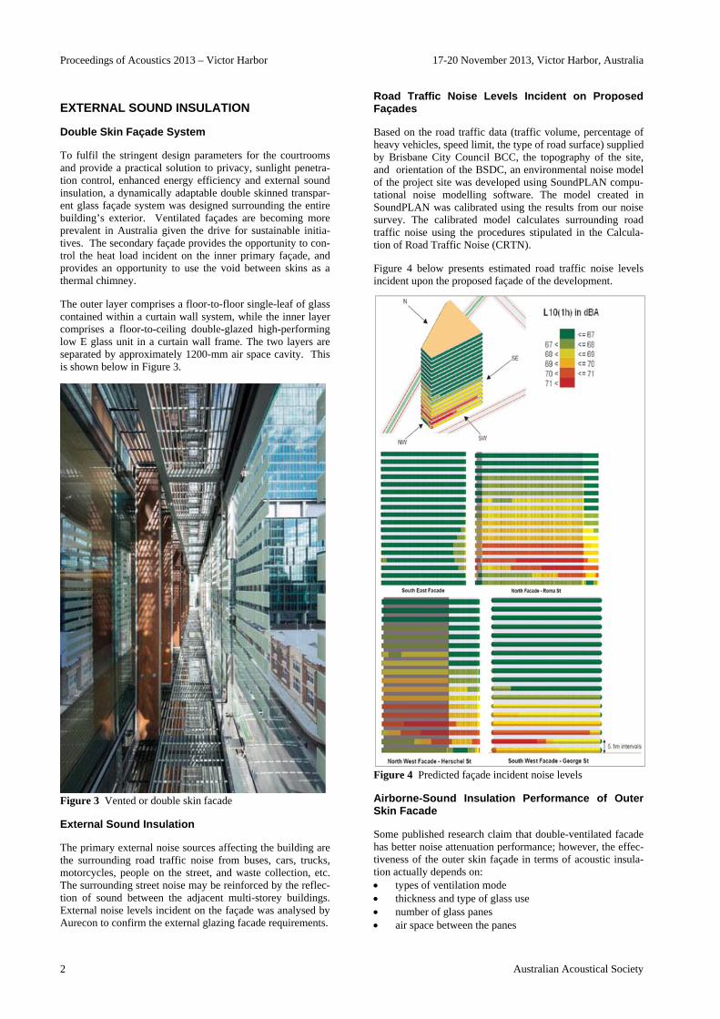
Based on the road traffic data (traffic volume, percentage of heavy vehicles, speed limit, the type of road surface) supplied by Brisbane City Council BCC, the topography of the site, and orientation of the BSDC, an environmental noise model of the project site was developed using SoundPLAN compu-tational noise modelling software. The model created in SoundPLAN was calibrated using the results from our noise survey. The calibrated model calculates surrounding road traffic noise using the procedures stipulated in the Calcula-tion of Road Traffic Noise (CRTN).
Figure 4 below presents estimated road traffic noise levels incident upon the proposed façade of the development.
Figure 4 Predicted façade incident noise levels
Airborne-Sound Insulation Performance of Outer Skin Facade
Some published research claim that double-ventilated facade has better noise attenuation performance; however, the effec-tiveness of the outer skin façade in terms of acoustic insula-tion actually depends on: types of ventilation mode thickness and type of glass use number of glass panes air space between the panes

Proceedings of Acoustics 2013 – Victor Harbor 17-20 November 2013, Victor Harbor, Australia
Australian Acoustical Society 3
As shown in Figure 5 below, Blumenberg et al (2006) re-ported improvements of between 14dB (with openings across the second skin) to 19dB (with openings at the perimeter of the second skin). This is in contrast to Oesterle et al (2001), and Blasco et al (2004) have reported an improvement of between 4 to 8dB.
Figure 5 Suggested sound insulation performance of vented facades (in section), Blumenberg et al (2006).
To understand the likely noise reduction achieved by vented facades, predictions and measurements were carried out at the Adelaide’s Commonwealth Law Courts as shown in Fig-ure 8 (equivalent continuous noise levels were measured in third-octave bands concurrently by two abseilers). The per-formance of the façade with openings at the perimeter is shown in Figure 6 below. An average reduction of about 5dB in incident noise levels is apparent for octave bands above 125Hz. At 125Hz and below, the spacing of the second skin from the primary introduces resonance effects between the skins which increases incident noise levels on the primary façade.
Figure 6 Measured sound level difference at centre and sides (left/right, top and bottom) of the large vented facade (Ade-laide Commonwealth Law Courts).
Estimates of noise reductions can be made using theory for sound radiated in flat spaces with specularly reflecting sur-faces using theory developed by Kuttruff (1985), reported in Bies and Hansen (2003):
⟨ ⟩4
12 11
Where is the source sound power (can be modelled as sound power per unit length), the acoustic impedance, the distance from the noise source, and the reflection coef-ficient. Similarly resonances within the cavity between fa-cades can be modelled using Boundary Element (BEM) Software, with typical results shown below in Figure 7.
Figure 7 Modal analysis of vented façade cavity (0.5m deep, about 10m x 20m) using BEM.
Figure 8 In-situ measurements of vented façade (Adelaide Commonwealth Law Courts)
These results were used to predict the likely noise reduction from the vented façade for the new courts building in Bris-bane. However, installation of such an extensive second skin required gaps between glass panes. The width of these gaps effected not only the noise reduction provided, but also intro-duced the potential for wind noise through slots in the façade. Estimates of the noise reduction were made using composite transmission loss theory, taking into account the transmission loss of a slot, and the percentage open area of the second skin.
Commissioning measurements were carried out using a dual channel spectrum analyser, with the microphone measuring the external traffic noise levels positioned at approximately 2m away from the façade. The other microphone was placed within the cavity at the respective height. The equivalent continuous noise levels on outer and inner sides of the exter-nal skin façade were measured concurrently. Results of measured and predicted noise level differences between the internal and external surfaces are shown in Figure 9.

Proceedings of Acoustics 2013 – Victor Harbor 17-20 November 2013, Victor Harbor, Australia
4 Australian Acoustical Society
Figure 9 Measured and predicted noise reduction across a secondary skin
In summary, results of in-situ testing of the airflow cavity at the Brisbane BSDC and Adelaide Commonwealth Law Court buildings revealed an average improvement of 4-8 dB over with a vented façade, however consideration needs to be given to cavity resonances below 125Hz.
Vented Facades – Aero-acoustics
Noise from airflow through or across slots in the second skin of the façade can be estimated using theory presented in Beranek (2003). The sound power level can be estimated from:
10 10
Where is the net pressure coefficient measured across the façade, is the incident velocity across a surface of area . To estimate the pressure coefficient (and to determine clad-ding pressures for use in the façade design), Aurecon’s build-ing sciences team carried out wind tunnel testing, with a scale model (1:400) of the building and surrounds as shown in Figure 10.
Figure 10 Wind tunnel model of the building with remova-ble secondary façade
Net pressures across the façade for a 1 in 1000 year return period (ultimate limit state) peak (gust) wind speed of 60m/s (at a reference height of 10m) are shown in Figure 11. This can be factored down and converted to a mean wind speed subject to the return period required. Based on the theory
outlined above and the results from our wind tunnel test, it was determined that the slot width should be no less than 20mm to avoid generation of Aeolian tones based on an an-nual return period wind speed.
Figure 11 Peak pressure differential across the secondary façade (kPa).
INTERNAL AIRBORNE SOUND INSULATION
Extensive testing and design advice for glazed partition and door systems was carried out in conjunction with the glazing contractor to ensure the systems installed on site would com-ply with the required DnTw ratings. This required a degree of design development with the contractor, with modifications made to the glass thickness, air-gap and infill material to optimise the acoustic performance yet conceal absorption to the reveals and enable practical installation and cost effec-tiveness. Modelling methods were adjusted to allow for vari-ations in stiffness due to the size of glass panels and the lack of mullions or framing between panels (which had the benefit of improving the sound insulation performance).
Figure 12 Image of interfaces between courts – walls, soffit, floor etc.
High performance light-weight (plasterboard/fibre cement) partitions were typically constructed using D-Studs staggered in top/bottom tracks specifically selected to meet the high

Proceedings of Acoustics 2013 – Victor Harbor 17-20 November 2013, Victor Harbor, Australia
Australian Acoustical Society 5
floor-floor spans. However the floor to floor height reduced the sound insulation performance of single stud partitions given the stud thickness needed to be increased above that commonly used to suit the span. The impact of stud resili-ence (affected by stiffness) has recently been highlighted by Betit (2010), with a 5dB reduction in performance with in-creasing thickness of stud (stiffness) noted. This was over-come through the use of resilient channels or additional plas-terboard linings.
Figure 13 Sound transmission loss of partition with varying stud thickness (Betit, 2010)
When complete, the sound level difference was measured between courts horizontally and vertically, with DnTw of 59 (-1,-2) achieved.
IMPACT SOUND INSULATION
Impact sound ratings were predicted using previous work carried out by Asdrubali and D’Alessandro (2008), with measured results of raised access floors on a concrete sub-strate with and without a suspended ceiling below shown in Figure 14. The use of a damping layer under the steel sup-port posts, comprising 3mm thick vulcanised rubber, pro-vides an equivalent impact noise rating to the floor surface covered with carpet.
The floor construction is typically 400mm deep with up-turned beams, with Beranek (2003) noting that the radiated sound power varies inversely with the cube of the slab thick-ness as given by:
105.1
120 10
Where is the density of air (kg/m3), is the speed of sound (m/s), is the radiation efficiency of the slab, the lon-gitudinal wave speed (m/s), the composite loss factor of the slab, the thickness of the slab (m), and the density of the slab material. Hence increasing the thickness will reduce the impact noise rating to about Lnw 35 (noting also the changes in radiation efficiency with increasing thickness).
Installation of the resilient pad under the pedestals affected the smoothness of the floor finish given the non-uniform imposed load (seating, furniture). Commissioning measure-ments on-site were made difficult due to background noise at the time of the measurements, however a rating in excess of FIIC 65 was obtained (less than Lnw 45).
Figure 14 Impact noise ratings (Lnw) for raised access floors (Asdrubali and D’Alessandro, 2008)
ROOM ACOUSTICS
The room acoustics of critical listening rooms was challenged to some extent by the imposed form and finishes of these spaces. The volume of the larger court spaces (refer to Fig-ure 15) was around 1,000m3, with the Schroeder frequency (used to define regions of room acoustic behaviour, ie. mod-al, diffuse, absorption) .down at about 60Hz (based on a de-sign criterion for the reverberation time of about 1.0 sec). The critical frequencies for speech are 250Hz to 2kHz, hence the driver in the design process was control of reverberation time and stray reflections (including flutter echoes) to max-imise speech intelligibility. Smaller spaces such as interview and conference rooms required consideration of their modal response, particularly in rooms used for protected or vulnera-ble witnesses.
Figure 15 Finishes within a typical court
Modelling was carried out using EASE ((Electro Acoustic Simulation for Engineers) which uses a ray-based approach to assess the mid to high frequency response of spaces, dif-fuse field parameters, and time domain parameters.
Our EASE models were calibrated in a mock-up court built primarily to assess functionality and aesthetics of a typical court. In addition, auralisation was used to demonstrate the impact on speech intelligibility of alternative finishes.
While the hard reflective finishes of the concrete soffit, tim-ber floor and high level glazing may seem disadvantageous, there are some benefits:
The underfloor cavity acted provided low frequency absorption, acting as Helmholtz resonator with openings to the cavity via unducted swirl diffusers.
The large unframed glass panes acted as low frequency absorbers. Measured damping loss factors for framed or

Proceedings of Acoustics 2013 – Victor Harbor 17-20 November 2013, Victor Harbor, Australia
6 Australian Acoustical Society
unframed glazing have been measured by Quirt (1982). Similar results have been found by Tadeau et al (2001).
The design approach was as follows:
Provide absorption at audience level with the mid fre-quency response controlled using slotted timber panels tuned to the required frequency based on slot width/length, thickness of facing panel and flow resistiv-ity of acoustic backing. The high frequency response was controlled using upholstered seating.
Use the seats and tables to provide diffusion to control flutter echoes between the ceiling and floor;
Low frequency response controlled using absorption in the floor cavity and resonant response of glass walls.
The results of predicted and measured reverberation times are shown in Figure 17, with significantly more low frequency provided by the glazing than estimated.
Figure 16 EASE model of typical court
Figure 17 Predicted and measured reverberation time for a typical court
BUILDING SERVICES
Figure 18 shows the typical sub-floor duct layouts, with floor-by-floor air handling units supplying to adjacent the court (perimeter and internal zones) and a more distant court. Perimeter zones are ducted, while interior zones use the floor void as a plenum. Key design issues included:
Limits for duct velocities (with and without internal lining) to minimise radiated noise from air flow.
Duct thickness and internal lining requirements to con-trol flanking noise between courts without introducing additional attenuators.
Sizing attenuators to control break-out noise from AHUs and down-duct noise to the plenum or discharge diffus-ers
Detailing of penetrations through sub-floor walls Plant-rooms were of unducted return/fresh-air type,
hence traffic and AHU noise was controlled through the sound insulation performance of the division wall and return-air attenuator to the plant-room.
Space constraints required return air from the courts to be ducted back to the plant-room via the public lobby through a common plenum as shown in Figure 19. Es-sentially the courts were separated from each other and the public lobby by only sound attenuators which were carefully designed to ensure the required level of sound isolation was achieved between courts.
The procedures for these analyses are well established in texts such as Bies and Hansen (2003) and Ver and Beranek (2005).
Figure 18 Duct layout
Figure 19 Return air path between courts
Detailed specifications were provided for to limit sound pow-er levels and tonal noise from AHU’s, with suppliers noise data reviewed at the time of tender. However when AHU’s were received, testing off-site, revealed an audible tone was evident at about 160Hz from the Ziehl-Abegg radial blade fans (required to achieve the required pressure within the discharge plenum of a multi-zone unit). While attenuators were adequate to comply with the low background noise levels within the courts, resonator silencers were designed and tested to ensure a solution was available should tones be audible on completion.

Proceedings of Acoustics 2013 – Victor Harbor 17-20 November 2013, Victor Harbor, Australia
Australian Acoustical Society 7
SOUND REINFORCEMENT
The architect’s vision for simple spaces prevented the use of conventional technology for sound reinforcement in the large expansive foyer spaces. It was intended to use beam steered arrays (phase shifted column loudspeakers) mounted on the walls to direct sound to the public areas as was done for the Ceremonial (BANCO) Court, however loudspeakers were to be concealed and sound absorption was to be avoided.
The solution to achieve the architect’s vision was to use lo-calised, omni-directional loudspeakers mounted in the floor to provide a low level of sound reinforcement. While this has been done on other projects with sub-floor loudspeakers used to provide masking noise to improve privacy within offices, the use of loudspeakers mounted within floor air-conditioning ducts below diffusers has not to our knowledge been done before.
One of the author’s past experience with distributed mode loudspeakers for the audio industry, Mackenzie (2002), was adapted for this application.
A brief discussion of sound radiation due to concentrated forces on plates follows. The dynamics of structures was outlined in Gaekwad and Mackenzie (2013) in terms of ad-mittance. In a similar way the mean square velocity at the driving point, , or at any other point , on a two-dimensional plate (using impedance rather than admittance) is given by Fahy (1985):
2 ∗
2 ∗
Where is the mode shape for mode , the modal imped-ance, 1 ⁄ , and the modal mass
given by , with the surface area of the panel. Given modes are orthogonal, it can be shown that the spatial average mean square response is given by (with
):
⟨ ̅ ⟩2
It is apparent that the response at the driving point exceeds that at points remote from the driving point given phase can-cellation (ie. Cancellation of terms for ). The sound power radiated by vibration in the panel remote from the driving point, is then given by (with the radiation efficien-cy) the familiar expression:
⟨ ̅ ⟩
Clearly in order to maintain a uniform frequency response, the radiation efficiency must be constant across the frequency range of interest (eg. above the coincidence frequency). However this neglects the sound power radiated at the driv-ing point which as stated exceeds the average response from the plate (particularly for plates with moderate damping).
An alternative expression for the mean square velocity at the driving point can be derived using a wavenumber transform technique to solve the bending-wave equation (Fahy (1985)).
It can be shown that for frequencies well below the critical frequency of the plate, the sound power radiated by the plate is given by (with the surface mass, the acoustic im-pedance):
4
This is the fundamental premise for the operation of flat pan-el or distributed mode loudspeakers, in that the power gener-ated by a finite, bounded plate is independent of frequency below the coincidence frequency, hence a relatively flat fre-quency response can be achieved if the radiation efficiency can be maintained at a constant level.
Given these results, with reference to Figure 20, a novel loudspeaker was designed to operate with a coincidence fre-quency of about 20kHz (low surface mass and bending stiff-ness), ensuring a relatively flat response up to about 5kHz. The panel perimeter and area were sized to ensure the lower frequency limit at which the radiation efficiency is main-tained is such that 10 10log 4⁄ . A light weight (about 0.5kg/m2), thin (less than 5mm), sandwich panel was selected to meet these criteria with metal skins ensuring ade-quate robustness within the floor diffuser environment.
Various types of exciters can be applied to the rear of the panel depending on the sensitivity required (eg. Electro-dynamic, piezo-ceramic, or magneto-strictive) and given spatial constraints. The location of the exciter must be con-sidered relative to the low frequency modal response of the plate (ie. the first mode at around 100Hz given the parame-ters described above). A high pass filter was introduced to further control the response at frequencies below 200Hz where the modal density was insufficient to provide a uni-form frequency response.
Figure 20 Theoretical modal average radiation efficiency of a baffled rectangular panel (Ver and Holmer, 1971)
The engineered product is shown below in Figure 21, with tests carried out at Krix’s testing laboratory in Adelaide (refer to Figure 21) demonstrating an omnidirectional sound field and uniform frequency response from 200-4000 Hz, with a sensitivity of 85dB (1W at 1m at 1kHz). Tapped line trans-formers were fitted to allow the speakers to be connected in a 100V line network.
Approximately 400 loudspeakers were installed in the build-ing, throughout the lobbies and courts. Components were imported and assembled in Adelaide, tested and then shipped

Proceedings of Acoustics 2013 – Victor Harbor 17-20 November 2013, Victor Harbor, Australia
8 Australian Acoustical Society
to Brisbane over a 6 month period. Extensive prototype test-ing was carried out to demonstrate the technology to Lend Lease.
Figure 21 Final product as installed and in the test rig (cour-tesy Soundmatrix)
CONCLUSION
This paper has highlighted some of the design challenges and innovations incorporated within the new Queen Elizabeth II Courts of Law in Brisbane. It has demonstrated application of an integrated building sciences approach to overcome these challenges and provide certainty to the client’s desired outcomes. The building has set a global benchmark for inno-vation in large public buildings and courthouse design and construction.
ACKOWLEDGEMENTS
We would like to acknowledge the support of Lend Lease, Architectus, Queensland’s Department of Public Works (Pro-ject Services) and the Justice and Attorney General’s De-partment. Additionally we would like to acknowledge the support of Aurecon’s project directors, Ben Coxon, Adrian Jenkins and Rob Hugall. Finally we would also like to acknowledge the contribution of Aurecon’s former employ-ees, David Lee and Mick Worthington.
REFERENCES
Fahy, F. (1985), “Sound and Structural Vibration – Radia-tion, Transmission and Response”, Academic Press Ltd.
Bies, D.A. and Hansen, C.H. (2003), Engineering Noise Con-trol-Theory and Practice”, 3rd Edn, Spon Press Ltd.
Gaekwad, J. and Mackenzie, N.C. (2013), “Dynamics of Wind Sensitive Sports Stadium Structures”, Annual Con-ference of the Australian Acoustical Society. Victor Har-bour, South Australia.
Mackenzie, N.C. (2002), “Distributed Mode Loudspeakers”, Annual Conference of the Australian Acoustical Society, Adelaide, South Australia.
Ver, I.L. and Holmer, C.I. (1971), In “Noise and Vibration Control” (L.L. Beranek, ed.), pp. 287-296. McGraw-Hill, New York.
Ver, I.L. and Beranek, L.L. (2006). “Noise and Vibration Control Engineering – Principles and Applications”, 2nd Ed., John Wiley and Sons.
Kuttruff, H. (1985). Stationare schallausbreitung in flachraumen, Acustica, 57, pp62-70.
Asdrubali, F. and D’Alessandro, F. (2008). “Impact sound insulating performance of access floors”, Acoustics 08, Paris.
Betit, A. (2010). “Performance Details of Metal Stud Parti-tions”, Sound and Vibration Magazine, pp14-16.
Tadeu, A.J.B. and Mateus, D.M.R. (2001). “Sound Transmis-sion through single, double and triple glazing. Experi-mental evaluation”, Applied Acoustics, 62, pp307-325.
Quirt J. (1982). “Sound transmission through windows I. Single and double glazing”, Journal of the Acoustical So-ciety of America, 72(3), pp834-44.
Blasco, M. Crispin, C. and Ingelaere, B. (2004). “Acoustical Performances of Double Ventilated Glass Facades”, In-ter-Noise 2004.
Oesterle, E., Lieb, R-D., Lutz, M. and Heusler, P. (2001). “Double Skin Façades: Integrated planning. Building Physics, Construction, Aerophysics, Air-Conditioning, Economic Viability.”, Prestal Verlag GmbH.
Blumenberg, J., Spinnler, M., Sattelmayer, T. (2006). “Dou-ble-skin façade systems - a comprehensive review on thermal and energetic behaviour”, International Confer-ence on Recent Advances in Heat Transfer, Karunya In-stitute of Technology and Sciences, Coimbatore, India