acoustic levitation report - university of illinois · acoustic levitation is recently developed...
TRANSCRIPT

1
Acoustic Levitation
Jason Yang, Michael Redlich
Experiment March 13th through April 24th
Abstract
Acoustic Levitation is recently developed experiment based on acoustic pressure counteracting gravity. We used ultrasonic transducer to provide sound pressure because it is in inaudible range with optimized pressure. A reflector plate set opposite of the transducer provides a standing wave when
located at the correct distance. Styrofoam bits are used as levitation material because they are relatively light and have larger surface. Using the described design we tested several properties of acoustic
levitation systems. We discovered that the curvature of the reflector plate did little to change the system, that we could create up to seven nodes, and that new properties emerged when we used a double
transducer setup. However, the pressure microphone was unable to record data on the ultrasonic device, so we used computer simulation called COMSOL to see the theoretical pressure field.
I. Introduction With a transducer connected to a driver board placed on a table and a reflector
plate overhead we had designed a simple mechanism for acoustically levitating small, low density, materials. Using (nonmetal) tweezers we carefully placed small bits of Styrofoam that we had shredded earlier into the acoustic beam. Most of the time we failed to levitate the object. Largely this was due to the empirical nature of the setup; without accurate measurements from the oscilloscope we were unable to determine whether or not we had a standing wave so we had to make small adjustments to the height of the reflector plate and continue placing objects into the beam with the tweezers until we were successful. When we were successful we made note of the distance measurement between the reflector plate and the transducer. However due to the fluctuations in temperature and humidity those measurements did not guarantee success if we were to retry at a later date. Therefore we advise that a microphone capable of making measurements in the ultrasonic is necessary not only to gather data but also to set up the system reliably. Experiments related to the curvature of the reflector plate, the material levitated, pressure nodes, and double transducers were carried out on the general system described.

2
II. Theory
A transducer is placed at the base of the system vibrating rapidly. This vibration released sound pressure waves of a certain wavelength related to the frequency of vibration. When a rigid reflector disk is placed somewhere above the transducer, a large percentage of the wave pressure is reflected back towards the transducer. Thus, by modifying the distance between the transducer and the reflector it is possible to create standing waves ‐ a wave front that does not change with time. The standing pressure wave has a certain quality that we are interested in exploiting. At the nodes, the pressure level is at a minimum such that the pressure is greater above and below the point due to the placement of the anti‐nodes and around the point where the pressure is equal to atmospheric pressure. A particle placed at this point would therefore feel a constant pressure in the radial direction point inwards. If we choose a particle material carefully it is possible to use the pressure differential to defeat the force of gravity and levitate the particle. Pressure is equivalent to force per unit area. Therefore we would like to maximize the surface area of the particle in question to take advantage of as much of the acoustic pressure as possible. However, the force of gravity is proportional to the mass of the particle so ideally we would like to find a material that would allow for a large surface area combined with a low mass, something of low density such as Styrofoam.
Fig.1

3
III. Experiment
1. Instrumentation a. Ultrasonic transducer (26.6kHz)
It takes electrical signal and vibrates to provide acoustic pressure. We used a transducer that that was advertised to vibrate 28000 times per second which produces 28kHz sound signal. We chose ultrasound frequency because the system should operate at around 140dB which is beyond the threshold of pain of human sensitivity. When actually tested the transducer was found to produce a 26.6kHz signal.
Fig.2 Set Up
b. Aluminum reflector It was necessary to use a reflector to produce standing waves.
Some qualities of reflector are curvature and absorptivity. We chose flat aluminum reflector to conduct the initial experiment. It was chosen because its absorptivity is low and reflects the majority of

4
incoming wave. We also wished to experiment with curved reflectors to see if the system can be more optimized to levitate.
c. Driver board The driver board we used was specialized for ultrasonic generator. It admits electrical power and transforms it to signal for the transducer to accept. We additionally put a switch between the power supply and the driver board to turn it on and off.
d. Oscilloscope We attached a pressure microphone near the reflector to observe
standing waves on oscilloscope. Unfortunately, the pressure microphone was not suited to ultrasonic generator, so we were unable to see standing waves.
2. Goals a. Curvature
We wished to experiment with different curvature of reflectors. Initially the experiment was in progress with a flat reflector and we successfully levitate several Styrofoam bits. After that, we hoped to use curved reflector to focus the acoustic pressure to levitate more Styrofoam bits.
b. Number of nodes By generating standing waves, there are a number of nodes
depending on the distance between the transducer and the reflector. The greater the distance, the less acoustic pressure is, so beyond certain distance, it would become impossible to levitate. We hoped to find the limit of the number of Styrofoam bits with given equipment.
c. Material With Styrofoam bits being successfully levitated, we started to
wonder if there was potential to levitate other materials. We needed to look for other materials like Styrofoam in that they should be of low enough density such that the force of gravity is small as compared to the acoustical force being brought to bear. Furthermore it had to be possible to find chunks of the material small enough to place into our system. Some candidate materials were: water droplets, sand grains, and insects.
d. Double transducer Instead of using the curved disk to provide the reflected wave
necessary to produce a standing wave we thought that it would be possible to use a second transducer placed above the first and facing it. If we placed the transducers at the right phase relative to each

5
other we should be able to produce standing waves just as before but with much greater intensity. This should allow us to levitate more Styrofoam bits. However, this experiment comes at the cost of possibly being less stable. If the two signals are off by just a little it could be impossible to create a standing wave.
3. Results
a. Curvature In place of the reflector dish we placed a focusing lens which,
importantly, is a curved (concave) piece of glass. Wearing googles in case the sound pressure was great enough to break the glass, we ran the experiment again. Luckily for us the integrity of the glass held and we were able to continue. An unforeseen benefit to using glass was that we were now able to view the experiment from the top. We were able to successfully create stable nodes at which we could levitate bits of Styrofoam. However the curved dish seem to do little for increasing our levitating power. Indeed, it seemed to have the effect of scattering the pressure waves making it more difficult to properly place the Styrofoam at the nodes. Instead of our unsuccessful attempts merely dropping onto the surface of the transducer many were violently thrown from the system and into surrounding laboratory areas.
b. Number of nodes The most obvious metric for success in our experimentation is just
how many stable nodes we can create at once while maintaining the acoustical power to levitate our particles. In order to focus the acoustic pressure beam we screwed a horn into the top of our transducer. A great deal of the vibrational power from the transducer is transferred to this horn which is a cylinder with a much smaller top surface area than the transducer. We figured that this would have the beam dissipate less rapidly than it otherwise would. Our finest attempt which was completed used the flat reflector, had us stably levitating seven Styrofoam bits at once. We declare an open challenge for anyone to top our record. We did run into some problems. Without an oscilloscope reading we have to create standing waves empirically. We knew roughly the wavelength of the pressure wave based on the advertised frequency of the transducer. However the error involved with the specifics of the environment such as temperature and humidity were beyond our power of calculation. As a result we largely had to guess a distance and make small adjustments until we found the sweet spot. Due to the length
6
scales involved this requires a very fine adjuster and a steady hand. To makes matters even more difficult as time went on both the circuit and the transducer would heat substantially. The heat from the transducer appeared to have an effect on our ability to successfully levitate objects. We believe that the heat either dispersed the power of the pressure wave or, more likely, made the particles themselves less stable and therefore more difficult to levitate with regularity.
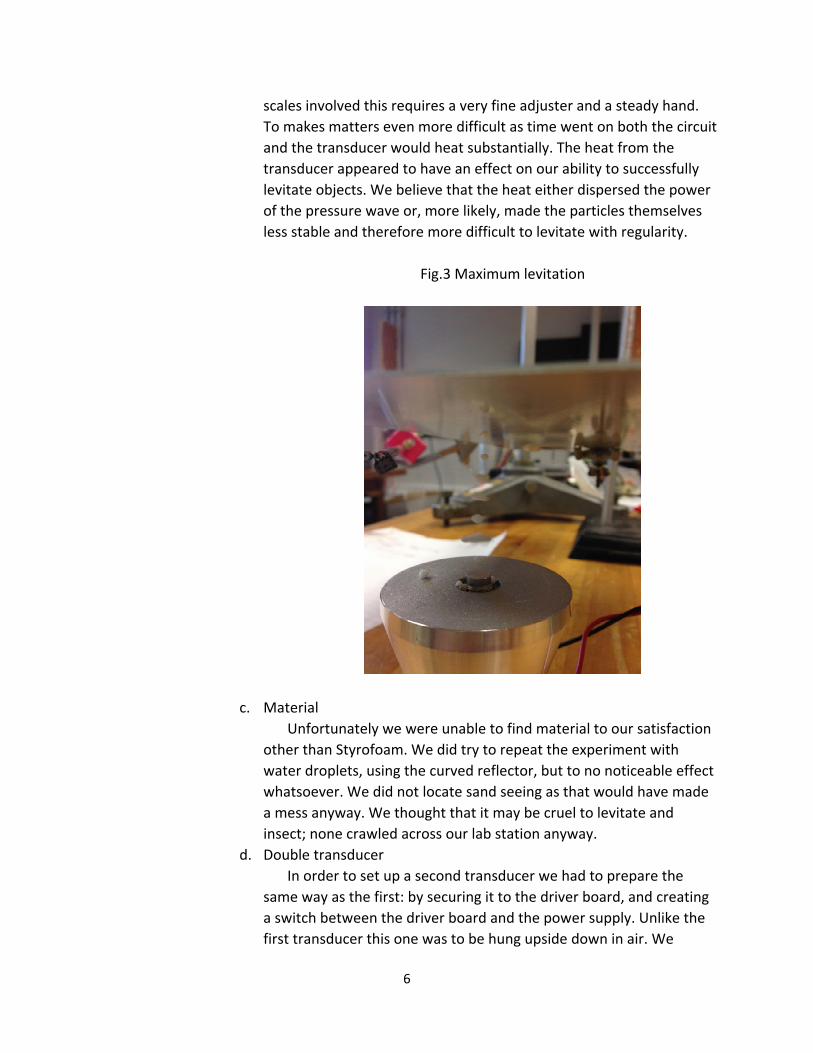
Fig.3 Maximum levitation
c. Material Unfortunately we were unable to find material to our satisfaction
other than Styrofoam. We did try to repeat the experiment with water droplets, using the curved reflector, but to no noticeable effect whatsoever. We did not locate sand seeing as that would have made a mess anyway. We thought that it may be cruel to levitate and insect; none crawled across our lab station anyway.
d. Double transducer In order to set up a second transducer we had to prepare the
same way as the first: by securing it to the driver board, and creating a switch between the driver board and the power supply. Unlike the first transducer this one was to be hung upside down in air. We

7
carefully selected a pair of rubber clamps sturdy enough to do the job. The relative beauty of the reflector, especially the flat one, is that only very rough alignment is required. As long as some bit of the disk was above the transducer satisfactory reflection would occur. However, with the second transducer it became necessary no only to ensure that they were parallel but that the transducer horns were perfectly aligned with each other. This posed a significant problem as we tried to set up the experiment. However, with some patience, it is possible to get it running in this fashion. The double transducer produced a pressure field other than what we were expecting. While there appeared to be the regular nodes at even intervals between the transducers, there also seemed to be a ring of low pressure at the top of the first transducer; particles trapped traced a circular path around and around the transducer horn. We were able to levitate several bits of Styrofoam at the traditional nodal points, however we were unable to beat or even match our record of seven. Other than the imperfections of the alignment playing a greater role, there was a problem in placing the Styrofoam in the system. Whenever we placed the tweezer into the path of the beam to release a particle it seemed to have a distorting effect on the pressure field causing whatever particles we were levitating to drop.
4. COMSOL
Due to the limitations of the microphones available to us we were unable to retrieve data relating to the acoustics of the system very accurately. We were unable to get a waveform on the oscilloscope which made it very difficult to create a standing wave. We were also unable to determine pressure fields, particle displacement velocities, or any other acoustic data metrics.
We decided to use COMSOL, a program were one may design acoustic systems, to attempt to find some theoretical structure for our experiment. After we had run most of our experiments we attempted to design a very similar system in COMSOL with a curved reflector plate. The program then gave us 2‐D plots of the particle trajectory, sound pressure level, and acoustic pressure which are shown below. COMSOL is a good program with many features that the user may vary most importantly, the geometry of the system.

anwe
The plots g
nd the reflece would hav
give a roughctor but we bve liked.
8
Fig. 4 Acous
h idea of whabelieve that
Fig. 5 Sound
stic Pressure
at is occurrinour COMSO
d Pressure L
e
ng between OL design wa
evel
the transduas not as exa
cer act as

IV
V. Safet1. Tr
thwiEr
10vo
fraallsinimth
he
2. Dr
cowisw
bo
ty ransducers
The transdey warmed ings where trrede was suUsing a vo
0 mega‐ohmolts. We advi
After the tagile. It is iml. This is partnce one tranmperative to e base of thAs the tran
eavily unadv
river Board The only s
onnecting it tires, once atwitch.
While the oard made a
Fig. 6 P
ducer were sto room temthe driver boubject to an uoltmeter ands, we were aise caution.transducers mportant to hticularly truensducer musmake sure te transducensducer is ruvisable to tou
afety issue wto the transdttached, are
system ran,n increasing
9
article Traje
shipped to umperature a oard cord wounfortunated two resistoable to dete
have warmehold them bye when runnst necessarilythe a rubberr. unning the touch.
we had withducer. It is ncompletely
however, wgly nontrivia
ectories
us in a low tevoltage diffould later bee shock as a rors, one of 10ermine that t
ed, they are y the base aning the douy be clamper clamp is us
op surface h
the driver bnecessary thacovered by
we did occasl humming n
emperature ference was e connectedresult. 0 kilo‐ohms the system r
still both daand not toucuble transducd in the vertsed and that
heats up con
board was wat one is certape before
ionally noticnoise and als
environmencreated on t. Professor
and anotheruns at 13,60
angerous andh the wings cer experimtical positionit only hold
nsiderably. It
while we werrtain that thee flipping the
ce that the dso warmed u
nt. As the
r of 00
d at ent; n it is onto
t is
re e e
driver up

10
considerably. This did not cause any problems for us, however we are not clear of the ramifications of leaving the board running for too long.
3. The Beam The acoustic beam is at an ultrasonic frequency (26.6 KHz) and runs at
130 decibels. We had no problems as far as the beam damaging the reflector plate materials, nor did we as ambient observers discover any issues. Additionally the materials we levitated did not display any signs of trauma that we could determine. It is extremely unwise to place any bit of one’s person into the path of the beam particularly eyes or ears. We are not sure exactly the outcome but we can be certain that it will not be beneficial.
4. Conclusion Within reason the design is sound enough such that experiments can be
carried out safely.
V. Conclusion Our project only scratches the surface of acoustic levitation. We have demonstrated that it can be done with a reasonable simple and elegant design. We have done some work in establishing potential pitfalls and difficulties in carrying out experiments. We are most proud of our double transducer design. Although a great deal of patience is required to set up the design and carry out experiments, we were able to look at some very strange and exciting behavior. Successor groups will be able to collect more data in the areas we were unable to satisfactorily explore. Materials other than bits of shredded Styrofoam should be tested in order to experimentally determine criterion for whether or not an object and be levitated. More experiments should be run to see how large levitated objects can be. We would have liked to have run further experiments on reflector plates with more substantial curve. Most importantly, further data is required to tease out the non‐linear components of the double transducer design.