acoustical evaluation of power skiving gears … · acoustical evaluation of power skiving gears...
TRANSCRIPT

ICSV21, Beijing, China, 13-17 July 2014 1
The 21st International Congress on Sound and Vibration
13-17 July, 2014, Beijing/China
ACOUSTICAL EVALUATION OF POWER SKIVING GEARS FOR HYDRAULIC PUMPS
Francesca Pedrielli, Eleonora Carletti CNR-Imamoter, National Research Council of Italy, Ferrara, Italy
e-mail: [email protected]
This paper describes the results of a research project aimed at evaluating to what extent the technology used for manufacturing the gear set can affect the performances of a gear pump. Two different kinds of gears were tested, the first manufactured according to the traditional process and the other one manufactured according to the skiving technology. Specific inves-tigations were performed in order to quantify the effects referring to the life cycle of the pump and its noise emission. As for the acoustical characterization, in particular, sound in-tensity measurements were carried out in different operating conditions in order to quantify the differences induced by the two gear sets on the emitted sound power level. The noise fre-quency content was also analyzed to quantify the noise impact of the two gear configurations on the perceived annoyance. Results confirmed the potentiality of the skiving technology to improve the pump performances in terms of efficiency and better resistance to wear and stress. Referring to the noise emission, the pump mounting the skiving gear set generated higher noise levels at the beginning; however, after 10,000 cycles of endurance tests the emit-ted noise was reduced at the same levels as that in the standard configuration. The noise lev-els further decreased while the pump working time further increased.
1. Introduction
Traditionally, the manufacturing process of gear sets for hydraulic pumps includes three main steps: the cutting phase, the finishing phase (shaving) and the final heat-treat phase by which the tooth flanks are properly hardened. In the last years, a different process was introduced, known as skiving technology, which involves the same initial cutting phase directly followed by the heat-treat phase. Then there is a final finishing phase which is done by skiving the tooth using a proper tool (skiving tool). The purpose is to compensate the tooth form distortions occurring after the heat treatment.
Studies on gear design and manufacture show that the skiving process leads to gear sets of higher quality compared with the traditional ones just because it permits to achieve a better tooth profile1,2. The gears obtained by the innovative skiving technique are also more resistant to wear and stress.
An Italian manufacturer of external gear pumps launched a research project to test if and to what extent pump performances change when skiving gears are used. This paper describes the re-sults of the acoustical characterizations performed on two different gear pumps when equipped with the standard and skiving gear sets. The acoustical differences have been evaluated in terms of emit-ted overall sound power level and frequency content.

21st International Congress on Sound and Vibration (ICSV21), Beijing, China, 13-17 July 2014
ICSV21, Beijing, China, 13-17 July 2014 2
2. Generation of noise in external gear pumps
An external gear pump consists of two meshing spur gears, usually with 9 to 12 teeth, en-closed in a closely fitting housing. These two identical gears come into and out of mesh to produce flow. One of them is driven by a motor and in turn it drives the other one. Each gear is supported by a shaft with bearings on both sides of the gear. Figure 1 shows an exploded view of such a pump.
Figure 1. Exploded view of an external gear pump.
The pumping action of a gear pump may be summarized as follows (see Fig. 2). As the gears
come out of mesh, they create expanding volume on the inlet side of the pump (low pressure). Oil flows into the cavity and is trapped by the gear teeth as they rotate. As the teeth engage on the outlet side, the volume between the two meshing teeth decreases and the oil is forced to the delivery port under high pressure3.
Inlet (Supply)
Outlet (Discharge)
Meshing Area Figure 2. Scheme of operation of an external gear pump.
The main causes of noise emission can be summarized as follows:
tangential tooth deflections induced during meshing and unmeshing; radial tooth deflections induced by fluctuating forces due to the sliding meshing teeth; oil and air jets occurring during the engagement cycle and resulting in speeds close to the sonic
level (cavitation effect). The above events produce noise at the gear meshing frequency and related harmonics. This
frequency is calculated by Eq. (1):
60
rpmnf teeth
m
. (1)

21st International Congress on Sound and Vibration (ICSV21), Beijing, China, 13-17 July 2014
ICSV21, Beijing, China, 13-17 July 2014 3
As a consequence of pumping action, pressure fluctuations are generated in the fluid which induce vibrations on the gears and on the case. When the frequencies of these vibrations coincide with the natural vibration modes of these two elements, they resonate and can act as acoustic radia-tors themselves, generating airborne noise. The actual entity of the noise emitted, however, depends on the dynamic characteristics of the system and the acoustic coupling between the vibrating sur-faces and the surrounding medium (air). Even the not perfect balance of the rotating parts or their eccentricity may generate vibrations and, therefore, airborne noise. [5]. This noise is concentrated at low frequencies while the noise components due to structural resonances are always in the high frequency range.
3. Experimental investigation
The experimental investigation was performed on two different pumps: a group 1 pump with a displacement volume of 4.2 cc/rev - Pump A; a group 2 pump with a displacement volume of 11 cc/rev - Pump B.
For each pump, three different 12-tooth gears were used: two gears were manufactured in a traditional way but came from different suppliers (F1 and F2); the third gear was manufactured us-ing skiving technique (F3).
The pumps were alternatively mounted on the same hydraulic test rig. The operating condi-tions of the whole system were constantly checked with suitable gauges. The rotational speed was hold at 1500 rpm. The working pressures were set at 50 and 200 bar, for different tests.
3.1 Test rig The tests were performed in the R&D Department of the company, using a test rig modified in
order to comply with the mounting conditions suggested by ISO 16902-14. A reflecting plane was placed at pump mounting surface and underneath, taking care of minimizing the vibration transmit-ted from the whole rig. There were non-rigid supports for prime mover and the inlet and discharge pipes were passing though the reflecting plane. As shown in Fig. 3, the test rig was modified for the acoustic test environment not being too reverberant.
Figure 3. Test rig, test environment and measurement instrumentation.
For this purpose, both reflecting planes were uncoupled from the pump and the hydraulic cir-
cuit. Moreover, the three walls enclosing the measurement surface were treated with sound absorb-ing material with an apparent acoustic absorption coefficient with good behavior from 250 Hz up-wards. Piping outside the measurement surface was shielded providing that this shielding did not account for more than 10% of the area of the measurement surface.

21st International Congress on Sound and Vibration (ICSV21), Beijing, China, 13-17 July 2014
ICSV21, Beijing, China, 13-17 July 2014 4
3.2 Data acquisition and measurement instrumentation The acoustic measurements were performed on site using sound intensity technique5,6 and
were aimed at comparing the noise emission of different pumps at different working pressures as a function of the gears fitted on them. The noise emission was quantified by: linear overall sound power level; linear sound power level spectrum, in 1/3 octave bands; percentage incidence of each frequency.
This latter parameter was calculated by Eq. (2)
100% TOT
ff W
W (2)
where Wf is the linear sound power value (Watt) of the f-th frequency band and WTOT is the linear total sound power value (Watt).
The acoustic characterization followed the test code described in ISO 9614-27. The method is based upon sampling of the intensity field normal to the measurement surface by moving an intensi-ty probe continuously along one or more specified paths. Measurements were performed so that an “Engineering” level of accuracy (grade 2) could be attained.
Measurements were made by means of a one-dimensional sound intensity probe equipped with ½" microphones and a 12 mm spacer and connected to a Bruel & Kjaer Pulse 9-channel ana-lyzer. Both analyzer and sound intensity probe met the requirements of class 1 instruments. Figure 4 shows the intensity probe during a sound power test.
Figure 4. One-dimensional sound intensity probe.
4. Results
The results reported in Fig. 5 show that pumps mounting skiving gears have a sound power level always higher than that of pumps mounting traditional gears, regardless the displacement vol-ume of the pump and the operating conditions. On the contrary, the difference between the overall levels of the pumps mounting traditional gears provided by different suppliers is not statistically significant.
When considering the frequency content, in many cases the pumps fitted with skiving gears show relevant components in the 2,000-3,000 Hz frequency range (shown later in Fig. 9). This be-havior could be explained by the teeth creation process. In fact, the skiving technique gives the tooth profile a typical ‘polyline’ shape. It creates a number of micro planes directly proportional to the number of teeth present on the skiving tool. This does not occur, however, in the case of stand-ard technique in which the profile of the tooth flank has a more homogeneous and curvilinear trend.

21st International Congress on Sound and Vibration (ICSV21), Beijing, China, 13-17 July 2014
ICSV21, Beijing, China, 13-17 July 2014 5
A zoom of the two profiles is shown in Fig. 6 and it allows the detection of the differences between the teeth made with the two different technologies.
Pump A 50 bar Pump A 200 bar Pump B 50 bar Pump B 200 barF1-F1 61.1 61.2 63.9 70.6F2-F2 61.1 61.7 65.1 72.0F3-F3 61.8 65.8 67.3 73.6
56
58
60
62
64
66
68
70
72
74
76
Ove
rall
soun
d po
wer
leve
l (dB
)Lw (dB) F1-F1 F2-F2 F3-F3
Figure 5. Overall sound power levels for 3 different gears, fitted on 2 different pumps at 2 different working pressures.
(a) (b)
Figure 6. Tooth profile for traditional (a) and skiving (b) gears.
In order to better understand if the presence of relevant frequency components may be related
to the different tooth profile, further acoustic measurements were carried out on all the pumps after specific ‘hard’ work cycles, normally used to test the pump endurance. The determination of the sound power level was then repeated every 10,000 endurance cycles. The expectation was that the continuous work of the pump may reduce the discontinuities localized on the tooth flanks.
The experimental results confirm this hypothesis as it can be seen in the following two bar charts, where the sound power levels already shown in Fig. 5 are compared to those emitted by the same pumps after achieving different levels of endurance. The level of endurance is identifiable by different shades of color: the darkest shade of color (F#-F#) represents new gears after break-in period; the second shade of color (F#end10-F#end10) represents gears after 10,000 endurance cycles; the third shade of color (F#end20-F#end20) represents gears after 20,000 endurance cycles; the fourth and last shade of color (F#end30-F#end30) represents gears after 30,000 endurance
cycles.
21st International Congress on Sound and Vibration (ICSV21), Beijing, China, 13-17 July 2014
ICSV21, Beijing, China, 13-17 July 2014 6
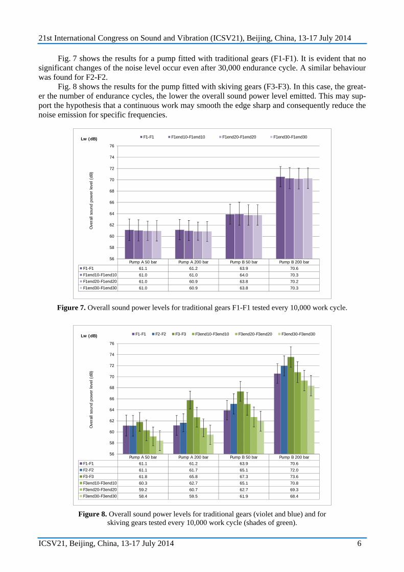
Fig. 7 shows the results for a pump fitted with traditional gears (F1-F1). It is evident that no significant changes of the noise level occur even after 30,000 endurance cycle. A similar behaviour was found for F2-F2.
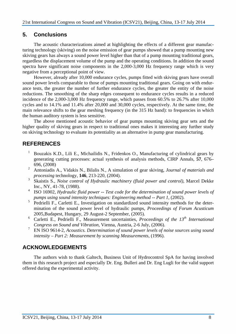
Fig. 8 shows the results for the pump fitted with skiving gears (F3-F3). In this case, the great-er the number of endurance cycles, the lower the overall sound power level emitted. This may sup-port the hypothesis that a continuous work may smooth the edge sharp and consequently reduce the noise emission for specific frequencies.
Pump A 50 bar Pump A 200 bar Pump B 50 bar Pump B 200 barF1-F1 61.1 61.2 63.9 70.6F1end10-F1end10 61.0 61.0 64.0 70.3F1end20-F1end20 61.0 60.9 63.8 70.2F1end30-F1end30 61.0 60.9 63.8 70.3
56
58
60
62
64
66
68
70
72
74
76
Ove
rall
soun
d po
wer
leve
l (dB
)
Lw (dB) F1-F1 F1end10-F1end10 F1end20-F1end20 F1end30-F1end30
Figure 7. Overall sound power levels for traditional gears F1-F1 tested every 10,000 work cycle.
Pump A 50 bar Pump A 200 bar Pump B 50 bar Pump B 200 barF1-F1 61.1 61.2 63.9 70.6F2-F2 61.1 61.7 65.1 72.0F3-F3 61.8 65.8 67.3 73.6F3end10-F3end10 60.3 62.7 65.1 70.8F3end20-F3end20 59.2 60.7 62.7 69.3F3end30-F3end30 58.4 59.5 61.9 68.4
56
58
60
62
64
66
68
70
72
74
76
Ove
rall
soun
d po
wer
leve
l (dB
)
Lw (dB) F1-F1 F2-F2 F3-F3 F3end10-F3end10 F3end20-F3end20 F3end30-F3end30
Figure 8. Overall sound power levels for traditional gears (violet and blue) and for
skiving gears tested every 10,000 work cycle (shades of green).

21st International Congress on Sound and Vibration (ICSV21), Beijing, China, 13-17 July 2014
ICSV21, Beijing, China, 13-17 July 2014 7
In all cases (Pump A and Pump B, at 50 and 200 bar), the sound power level emitted by pumps fitted with new skiving gears (F3-F3) is always higher than that emitted by pumps fitted with skiving gears after endurance cycles. After only 10,000 endurance cycles, in fact the reduction is important, although not always statistically significant, and the overall sound power levels are comparable with those emitted by pumps fitted with traditional gears. This improvement is even more evident when the endurance cycles increase.
A spectral analysis was performed in order to quantify the noise impact of the two gear con-figurations on the perceived annoyance. This analysis is reported in Fig. 9 for Pump A at 200 bar and it quantifies to which extent (see Eq. 2) each frequency band component contributes to the total linear sound power value. First of all, it shows the presence of the gear meshing frequency (fm = 300 Hz for a 12-tooth pump rotating at 1500 rpm) in the 1/3 octave band centered at 315 Hz (dark blue) that in many cases accounts for more than 35%, individually. In details: 40.4% for F1- F1 gears; 15.3% for F3- F3 gears; 37.0% for F3end10- F3end10 gears; 45.8% for F3end20- F3end20 gears; 48.1% for F3end30- F3end30 gears.
Then, it shows that the pump fitted with skiving gears have relevant components at medium-high frequencies - in the frequency range where the ear is most sensitive – that accounts for: 60.5% at 2500 Hz and 5.4% at 3150 Hz, for F3-F3 gears; 26.7% at 2500 Hz and 8.6% at 3150 Hz, for F3end10- F3end10 gears; 14.1% at 2500 Hz and 11.9% at 3150 Hz, for F3end20- F3end20 gears; 11.4% at 2500 Hz and 14.0% at 3150 Hz, for F3end30- F3end30 gears.
The comparison among the effects of different levels of endurance shows that the smoothing of the sharp edges results in a reduced incidence of the frequency band centered at 2500 Hz, which passes from 60.5% to 26.7% after 10,000 cycles and to 14.1% and 11.4% after 20,000 and 30,000 cycles, respectively. At the same time, the main relevance is shifted to the frequency band centered at 315 Hz, the gear meshing frequency.
It is worth noting that such a shift towards the low frequency range is very important from a perceptional point of view, as the human auditory system has its greater sensitivity in the frequency range 1,000-5,000 Hz.
0% 10% 20% 30% 40% 50% 60% 70% 80% 90% 100%
F3end30‐F3end30
F3end20‐F3end20
F3end10‐F3end10
F3‐F3
F1‐F1
Incidence on the overall value (%)
Pump A 200 bar
250 Hz 315 Hz 400 Hz 500 Hz 630 Hz 800 Hz 1000 Hz 1250 Hz 1600 Hz 2000 Hz 2500 Hz 3150 Hz 4000 Hz 5000 Hz 6300 Hz
Figure 9. Percentage incidence of each frequency evaluated for Pump A – 200 bar.
21st International Congress on Sound and Vibration (ICSV21), Beijing, China, 13-17 July 2014
ICSV21, Beijing, China, 13-17 July 2014 8
5. Conclusions
The acoustic characterizations aimed at highlighting the effects of a different gear manufac-turing technology (skiving) on the noise emission of gear pumps showed that a pump mounting new skiving gears has always a sound power level higher than that of a pump mounting traditional gears, regardless the displacement volume of the pump and the operating conditions. In addition the sound spectra have significant noise components in the 2,000-3,000 Hz frequency range which is very negative from a perceptional point of view.
However, already after 10,000 endurance cycles, pumps fitted with skiving gears have overall sound power levels comparable to those of pumps mounting traditional gears. Going on with endur-ance tests, the greater the number of further endurance cycles, the greater the entity of the noise reductions. The smoothing of the sharp edges consequent to endurance cycles results in a reduced incidence of the 2,000-3,000 Hz frequency range, which passes from 60.5% to 26.7% after 10,000 cycles and to 14.1% and 11.4% after 20,000 and 30,000 cycles, respectively. At the same time, the main relevance shifts to the gear meshing frequency (in the 315 Hz band): to frequencies in which the human auditory system is less sensitive.
The above mentioned acoustic behavior of gear pumps mounting skiving gear sets and the higher quality of skiving gears in respect to traditional ones makes it interesting any further study on skiving technology to evaluate its potentiality as an alternative in pump gear manufacturing.
REFERENCES 1 Bouzakis K.D., Lili E., Michailidis N., Fridenkos O., Manufacturing of cylindrical gears by
generating cutting processes: actual synthesis of analysis methods, CIRP Annals, 57, 676–696, (2008)
2 Antoniadis A., Vidakis N., Bilalis N., A simulation of gear skiving, Journal of materials and processing technology, 146, 213-220, (2004).
3 Skaistis S., Noise control of Hydraulic machinery (fluid power and control), Marcel Dekke Inc., NY, 41-78, (1988).
4 ISO 16902, Hydraulic fluid power -- Test code for the determination of sound power levels of pumps using sound intensity techniques: Engineering method -- Part 1, (2002).
5 Pedrielli F., Carletti E., Investigation on standardized sound intensity methods for the deter-mination of the sound power level of hydraulic pumps, Proceedings of Forum Acusticum 2005,Budapest, Hungary, 29 August-2 September, (2005).
6 Carletti E., Pedrielli F., Measurement uncertainties, Proceedings of the 13th International Congress on Sound and Vibration, Vienna, Austria, 2-6 July, (2006).
7 EN ISO 9614-2, Acoustics. Determination of sound power levels of noise sources using sound intensity – Part 2: Measurement by scanning Measurements, (1996).
ACKNOWLEDGEMENTS
The authors wish to thank Galtech, Business Unit of Hydrocontrol SpA for having involved them in this research project and especially Dr. Eng. Bulleri and Dr. Eng Lugli for the valid support offered during the experimental activity.