actions to improve coal seam gas drainage...
TRANSCRIPT
Black, D J and Aziz, N I, 2011. Actions to improve coal seam gas drainage performance, in Proceedings of the 11th Underground Coal Operator’s Conference COAL2011. University of Wollongong, (eds: N I Aziz, R J Kininmonth, J A Nemcik and T X Ren), Wollongong, 10-11 February, pp. 309-316
ACTIONS TO IMPROVE COAL SEAM GAS DRAINAGE PERFORMANCE
Dennis J. Black1,2
ABSTRACT: Coal seam gas drainage is affected by many factors, which may be generally divided into two groups, geological properties and operational factors. Studies conducted in the Bulli seam found geological factors had a dominant impact on coal seam gas drainage while operational factors had a secondary impact, affecting the amount of optimum gas drainage performance achieved within the limitations imposed by the prevailing geological conditions. Various operational factors, which are controllable by the mine operator, are presented and recommendations made to improve and optimise gas drainage performance.
and Naj I. Aziz1
INTRODUCTION
The use of inseam drilling ahead of mining for gas drainage was first introduced in Australia in 1980 to reduce the coal seam gas concentrations to levels sufficient to be managed by the mine ventilation system during both the roadway development and longwall coal extraction processes. Since 1980 underground to inseam (UIS) drilling has evolved from simple rotary drilling rigs to more advanced units which utilise down-hole motors and are capable of drilling borehole in the order of 1,600 m. The use of UIS drilling has expanded throughout the Australian coal mining industry to become the method of choice for underground gas drainage drilling, particularly in mining regions such as the Illawarra which operate at depths in the order of 450-500 m that have substantial surface access constraints which restrict access for surface based methods.
In gassy mines, such as those operating in the Bulli seam, it is common for substantial UIS drilling to be completed ahead of mine development, with more than 100 000 m drilled annually. The annual cost of such intensive drilling programs, along with supporting infrastructure, may be in the order of $4-6 million. Mechanisms that control and influence coal seam gas drainage are generally not well understood and therefore most coal mine gas drainage programs achieve less than optimum performance. Recent studies to evaluate the effectiveness of such intensive UIS gas drainage programs found that almost half the boreholes delivered little to no benefit to gas content reduction (Black and Aziz, 2008). Where difficult drainage areas are encountered a common response is to increase the borehole density, often allowing minimal drainage time for the additional boreholes; a high cost to achieve generally poor results.
Studies conducted in the Bulli seam in areas where seam gas was found to be extremely difficult to drain from the coal found geological factors, in particular the degree of saturation (DoS) and permeability had a dominant impact on gas drainage effectiveness, with gas drainage found to be most difficult from deeply undersaturated and low permeability coal. While prevailing geological conditions, which tend to cap total gas drainage potential operational factors, were found to affect the ability of coal seam gas drainage programs to achieve the potential maximum gas production performance.
The operational factors which are generally within the control of mine personnel to change as appropriate to optimise total gas drainage performance within the limits imposed by prevailing geological properties are discussed.
SELECTION OF GAS DRAINAGE METHOD
Many deep, gassy mines rely on UIS drilling to provide borehole for the purpose of coal seam gas drainage. The UIS method involves drilling boreholes into unmined coal from formed roadways to drain gas from the coal seam ahead of advancing mine development. With the UIS method both drilling and the time available to drain gas from the drilled area (drainage window) fall on the critical path of the mine production schedule. It is typical for the drainage window associated with the use of the UIS method is less than 12 months. In deeply undersaturated and low permeability coal seams the rate of reservoir pressure reduction can be extremely slow, often taking much longer than 12 months to reach the critical desorption pressure. In such conditions UIS gas drainage may not be capable of delivering the necessary gas content reduction within the time available.
The impact of prevailing geological conditions on the rate of gas emission from the coal seam must be understood and considered when selecting an appropriate gas drainage method, or combination of methods. Figure 1 shows estimated drainage time required to reduce the in situ gas content to the Level 1 outburst threshold limit using the UIS gas drainage method. In areas where the required drainage time exceeds the available drainage window alternative surface-based drilling and gas drainage methods must be used. A variety of drilling and gas drainage enhancement techniques are available and each is appropriate for use in a particular set of geological conditions. Surface-based drilling and gas drainage enhancement methods for example enable drilling and gas drainage to be conducted independent of mine
1 Department of Civil, Mining and Environmental Engineering, University of Wollongong, Australia 2 Pacific Mining and Gas Management (PacificMGM), www.pacificmgm.com.au

Black, D J and Aziz, N I, 2011. Actions to improve coal seam gas drainage performance, in Proceedings of the 11th Underground Coal Operator’s Conference COAL2011. University of Wollongong, (eds: N I Aziz, R J Kininmonth, J A Nemcik and T X Ren), Wollongong, 10-11 February, pp. 309-316 operations, preferably many years ahead of mining activity, and therefore avoid becoming a critical path activity on the mine production schedule.
Figure 1: Total time required (days) to reduce seam gas content to Bulli seam Level 1 outburst threshold limit
DESIGN OF BOREHOLE LAYOUT
The orientation of boreholes relative to (a) the principal horizontal stress, (b) the cleats and joints, and (c) the dip of the coal seam, impact gas drainage performance and therefore must be considered when designing the layout of the gas drainage drilling program. Typically boreholes oriented parallel to the major horizontal stress and perpendicular to the face cleat produce gas at an increased rate. The influence of both stress and cleat orientation on drainage performance should be investigated to determine which is the more dominant factor in the coal seam to be drained. In a study of factors impacting gas drainage performance in the Bulli seam, borehole orientation relative to the major horizontal stress was found to have a more significant impact on gas drainage than orientation relative to cleat.
The spacing between boreholes, i.e. drilling density, must also be considered. As shown in Figure 2, should the spacing between boreholes be too great the gas content of the coal seam midway between the drainage boreholes may be reduced below the required level within the available drainage period. Alternatively if the spacing between boreholes is too low interference occurs quickly and the intensity and cost of the drainage program becomes unnecessarily high.
Figure 2: Impact of borehole spacing in achieving effective gas drainage
DRILLING AND COMPLETION OF DRAINAGE BOREHOLES
Standpipes of sufficient length that extend beyond the zone of fracturing in the coal rib are necessary to reduce the risk of excessive gas leakage from the rib surrounding the borehole when the borehole has been shut-in and alternatively excessive air leakage through the rib to dilute the drainage gas when the borehole is producing and suction pressure is applied to the borehole. Likewise the standpipe should be effectively grouted into the borehole. It is good practice to conduct a pressure test on each standpipe following installation, prior to resuming drilling of the borehole, to determine if leakage paths exist.
As roadway development advances in adjacent panels each of the UIS boreholes is intersected. These open boreholes represent a source of potentially high air dilution entering the gas drainage system. The exposed borehole may be plugged or returned to operation, typically by using a length of hose with the ends inserted and grouted into the coal rib. The grouting of the plugs or hose ends into the coal rib must be to a high standard to minimise air dilution into the drainage range and reduce the rate of gas emission into the mine airways.
Following the introduction of directional drilling and the development of the DDM-MECCA in-hole survey system in the 1990’s there has been little change in the equipment and methods used for drilling UIS gas drainage boreholes. Although
Black, D J and Aziz, N I, 2011. Actions to improve coal seam gas drainage performance, in Proceedings of the 11th Underground Coal Operator’s Conference COAL2011. University of Wollongong, (eds: N I Aziz, R J Kininmonth, J A Nemcik and T X Ren), Wollongong, 10-11 February, pp. 309-316 industry funded projects have developed several generations of sensors and logging systems to improve drilling guidance and in-hole data collection the development process has stopped short of commercialisation and therefore technology has not been adopted by drill rig operators to improve UIS gas drainage performance.
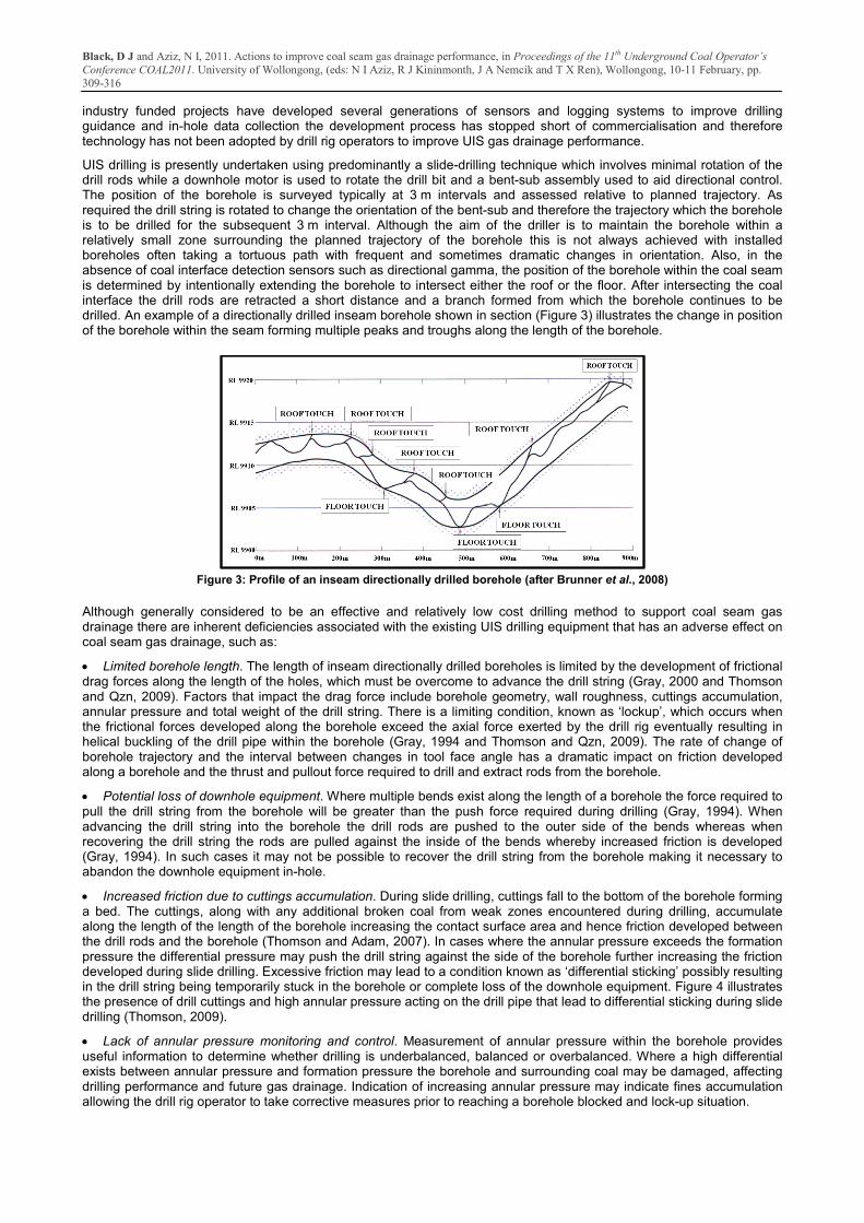
UIS drilling is presently undertaken using predominantly a slide-drilling technique which involves minimal rotation of the drill rods while a downhole motor is used to rotate the drill bit and a bent-sub assembly used to aid directional control. The position of the borehole is surveyed typically at 3 m intervals and assessed relative to planned trajectory. As required the drill string is rotated to change the orientation of the bent-sub and therefore the trajectory which the borehole is to be drilled for the subsequent 3 m interval. Although the aim of the driller is to maintain the borehole within a relatively small zone surrounding the planned trajectory of the borehole this is not always achieved with installed boreholes often taking a tortuous path with frequent and sometimes dramatic changes in orientation. Also, in the absence of coal interface detection sensors such as directional gamma, the position of the borehole within the coal seam is determined by intentionally extending the borehole to intersect either the roof or the floor. After intersecting the coal interface the drill rods are retracted a short distance and a branch formed from which the borehole continues to be drilled. An example of a directionally drilled inseam borehole shown in section (Figure 3) illustrates the change in position of the borehole within the seam forming multiple peaks and troughs along the length of the borehole.
Figure 3: Profile of an inseam directionally drilled borehole (after Brunner et al., 2008)
Although generally considered to be an effective and relatively low cost drilling method to support coal seam gas drainage there are inherent deficiencies associated with the existing UIS drilling equipment that has an adverse effect on coal seam gas drainage, such as:
• Limited borehole length. The length of inseam directionally drilled boreholes is limited by the development of frictional drag forces along the length of the holes, which must be overcome to advance the drill string (Gray, 2000 and Thomson and Qzn, 2009). Factors that impact the drag force include borehole geometry, wall roughness, cuttings accumulation, annular pressure and total weight of the drill string. There is a limiting condition, known as ‘lockup’, which occurs when the frictional forces developed along the borehole exceed the axial force exerted by the drill rig eventually resulting in helical buckling of the drill pipe within the borehole (Gray, 1994 and Thomson and Qzn, 2009). The rate of change of borehole trajectory and the interval between changes in tool face angle has a dramatic impact on friction developed along a borehole and the thrust and pullout force required to drill and extract rods from the borehole.
• Potential loss of downhole equipment. Where multiple bends exist along the length of a borehole the force required to pull the drill string from the borehole will be greater than the push force required during drilling (Gray, 1994). When advancing the drill string into the borehole the drill rods are pushed to the outer side of the bends whereas when recovering the drill string the rods are pulled against the inside of the bends whereby increased friction is developed (Gray, 1994). In such cases it may not be possible to recover the drill string from the borehole making it necessary to abandon the downhole equipment in-hole.
• Increased friction due to cuttings accumulation. During slide drilling, cuttings fall to the bottom of the borehole forming a bed. The cuttings, along with any additional broken coal from weak zones encountered during drilling, accumulate along the length of the length of the borehole increasing the contact surface area and hence friction developed between the drill rods and the borehole (Thomson and Adam, 2007). In cases where the annular pressure exceeds the formation pressure the differential pressure may push the drill string against the side of the borehole further increasing the friction developed during slide drilling. Excessive friction may lead to a condition known as ‘differential sticking’ possibly resulting in the drill string being temporarily stuck in the borehole or complete loss of the downhole equipment. Figure 4 illustrates the presence of drill cuttings and high annular pressure acting on the drill pipe that lead to differential sticking during slide drilling (Thomson, 2009).
• Lack of annular pressure monitoring and control. Measurement of annular pressure within the borehole provides useful information to determine whether drilling is underbalanced, balanced or overbalanced. Where a high differential exists between annular pressure and formation pressure the borehole and surrounding coal may be damaged, affecting drilling performance and future gas drainage. Indication of increasing annular pressure may indicate fines accumulation allowing the drill rig operator to take corrective measures prior to reaching a borehole blocked and lock-up situation.

Black, D J and Aziz, N I, 2011. Actions to improve coal seam gas drainage performance, in Proceedings of the 11th Underground Coal Operator’s Conference COAL2011. University of Wollongong, (eds: N I Aziz, R J Kininmonth, J A Nemcik and T X Ren), Wollongong, 10-11 February, pp. 309-316 Inseam directional drilling, under normal conditions, is ‘underbalanced’, whereby formation pressure exceeds the annular pressure of the circulating drilling fluid (Thomson and Qzn, 2009). The higher pressure of the formation in the underbalanced condition creates a pressure differential resulting in the flow of water and gas from the coal seam into the borehole (Thomson and Qzn, 2009). In underbalanced drilling, particularly where the pressure differential is high and when negotiating zones of weak coal and geological structures, the risk of the borehole collapsing around the drill string is increased. Rapid build-up of material within the borehole may disrupt fluid circulation causing increased annular pressure potentially causing differential sticking, mechanical jamming and borehole failure (Thomson and Qzn, 2009).
Where annular pressure exceeds formation pressure an ‘overbalanced’ condition is created. In an overbalanced condition the higher pressure of the borehole annulus forces drilling fluids and fines into the cleat and pores of the surrounding coal seam forming a ‘skin’ around the wall of the borehole which adversely impacts future gas drainage (Thomson and Qzn, 2009). Where the rate of fluid loss into the surrounding coal seam is high the velocity of drill fluid circulating in the borehole may be insufficient to effectively clear cuttings from the borehole potentially leading to increased friction and bogging of the drill string (Thomson and Adam, 2007). Figure 5 illustrates the nature of fluid and gas flow in underbalanced and overbalanced conditions associated with a localised failure within the borehole (Thomson, 2009).
A borehole pressurisation system was developed under ACARP project C3072 in the late 1990’s (Gray, 1998) however this system was not tested in an underground mine UIS drilling application and to this day UIS drilling continues without any form of monitoring or control of fluid pressure balance relative to the conditions present in the reservoir.
Figure 4: Effect of drill cuttings and annular pressure to increase drag forces leading to differential sticking of the drill string (Thomson, 2009)
Figure 5: Effect of overbalanced and underbalanced conditions in inseam drilling (Thomson, 2009)
Control of annular pressure may also offer some resistance to the adverse impact of stress induced borehole instability. Figure 6 illustrates the effect of excessive vertical and horizontal stress experienced by a borehole and the resulting stress induced failure (break-out). Creedy et al. (1997) suggested the strength of the material being drilled is the most important factor controlling borehole stability as lower strength materials are more likely to fail, particularly those affected by water. The magnitude and orientation of the stress field relative to the borehole can also have a significant impact on resulting stability. In areas where the coal seam is weak and there is an increased risk of coal failure and potential restriction or blockage of the borehole a liner should be inserted into the borehole
Figure 6: Impact of vertical and horizontal stress on borehole stability (after Brown et al., 1996)

Black, D J and Aziz, N I, 2011. Actions to improve coal seam gas drainage performance, in Proceedings of the 11th Underground Coal Operator’s Conference COAL2011. University of Wollongong, (eds: N I Aziz, R J Kininmonth, J A Nemcik and T X Ren), Wollongong, 10-11 February, pp. 309-316
COMPLETION
The presence of water in the coal seam and within a borehole tends to impede gas desorption. Therefore following drilling each borehole should be flushed to remove residual water and coal fines. When drilling using fan patterns there is an increased risk of connection between boreholes due to the high density close to the collar. In such cases drilling fluid may readily pass between borehole and it may be necessary to delay flushing until all holes in the pattern have been drilled. Where boreholes are aligned down-dip or deep troughs exist along the length of the borehole, subject to groundwater make, in-hole dewatering systems should be installed and used to maintain conditions conducive to gas drainage.
DESIGN OF GAS RETICULATION SYSTEM
To avoid discharging drained gas into the mine ventilation system and potentially creating an unsafe condition within the mine a gas reticulation pipe network may be utilised to remove the drained gas from the borehole directly to the surface where the gas may be utilised for power generation, flared or discharged directly to atmosphere. Prior to committing to a particular gas reticulation system the location, volume and concentration of the current and future gas sources must be assessed to ensure the pipe network is of sufficient size. Where pipe diameter is too small internal pressure losses may be very high restricting total gas reticulation capacity to less than may be necessary.
Vacuum is typically applied to the gas reticulation pipe network via a series of liquid ring pumps installed in a surface gas drainage plant. The purpose of the surface vacuum plant is to maintain the pressure throughout the underground pipe network at below atmospheric pressure so as to prevent gas leaking from the pipes into the underground mine airways. Applying a suction pressure of 10-15 kPa (gauge) to drainage boreholes is considered acceptable. Where increased suction is applied increased gas drainage is unlikely to be achieved whereas there is a far greater risk of air leakage into the system, which not only reduces the quality of the drainage gas but also reduces the effective area of the pipes and therefore the capacity of the gas reticulation system, as shown in Figure 7.
Figure 7: Reduction in effective area due to fines accumulation (Black and Self, 2007)
The design of the gas drainage reticulation system should also allow for the installation of measuring stations to record gas flow and composition, positioned at all major junctions throughout the network. Water traps should also be installed throughout the pipe network, particularly at the bottom of synclines and other low sections where water is likely to accumulate and create a restriction within the network. In order to reduce the risk of water and coal fines entering the gas reticulation pipe network gas/water separators should be installed and maintained to provide an interface between each gas drainage borehole, or group of boreholes, and the pipe range, particularly during the initial production phase of the boreholes. A separator unit, similar to the design shown in Figure 8, would be located near to the boreholes and receive all gas, water and coal fines, produced from the boreholes. Once inside the main body of the unit separation occurs with the seam gas exiting the top of the unit to the gas drainage range leaving the water and fines to be pumped and drained from the bottom of unit and removed from the site.
Figure 8: Conceptual gas, water, coal fines separation unit
Black, D J and Aziz, N I, 2011. Actions to improve coal seam gas drainage performance, in Proceedings of the 11th Underground Coal Operator’s Conference COAL2011. University of Wollongong, (eds: N I Aziz, R J Kininmonth, J A Nemcik and T X Ren), Wollongong, 10-11 February, pp. 309-316
MONITORING AND MANAGEMENT
Restrictions and blockages can easily occur within gas drainage boreholes due to an inflow of groundwater from the coal seam or failure of the coal seam surrounding the borehole. Such restrictions or blockages may dramatically slow or even prevent gas drainage and although water accumulation is more likely to occur early in the life of the borehole failure of the coal may occur at any time.
Dedicated resources should be assigned to regularly monitor and actively manage the performance of UIS gas drainage boreholes and the complete gas reticulation network. If the performance and status of the gas reticulation network is not continuously monitored, measurement of the pressure, flow rate and gas composition should be recorded at least weekly at each drill site, each panel entry, the entry to the surface gas drainage plant and all other major junctions throughout the network. The flow rate and composition of gas from each borehole should also be measured weekly. This information will enable all gas production sources to be quantified as well as identify sources of leakage and changes in system performance. Water production and applied suction pressure should also be recorded to enable detailed analysis and understanding of site specific gas drainage characteristics.
An important aspect of data analysis and reporting must be identification of changes in performance, for example a sudden decrease in gas production rate, excessive air dilution, or excessive water production. Regular monitoring enables potential issues to be identified, investigated, and appropriate corrective action to be taken.
CONCLUSIONS
From an assessment of operational factors that impact coal seam gas drainage the following is a summary of actions that should be considered by mine operators to optimise the performance of the total gas drainage program.
• Develop an understanding of the gas drainage characteristics of the coal seam to be mined. In particular, gather data and conduct testing to forecast maximum likely gas production based on prevailing geological properties.
• Determine suitable gas drainage method(s) based on review of mine production schedule and available gas drainage window.
• Design the drilling program considering increased gas production is likely from boreholes oriented parallel to principal horizontal stress and perpendicular to the face cleat and joints. Boreholes should ideally be drilled up-dip to facilitate removal of any inflow of groundwater to the borehole. When drilling down-dip is necessary and where troughs are present along the length of the boreholes that may allow water to accumulate in-hole dewater systems should be installed and maintained.
• Existing UIS drilling equipment and methods have an adverse impact on the drainage of gas from the coal seam due to lack of directional control that necessitates frequent changes in drilling orientation, branching and roof/floor touches. An absence of pressure control has the potential to create unstable conditions within the borehole and damage the permeability of the coal seam surrounding the borehole. The development of sensors and control systems to support automation of drilling guidance, used in conjunction with pressure sensing and control systems, would have a significant impact on increasing drilling productivity, reducing cost per metre drilled and improve total gas drainage performance.
• Standpipes should be of sufficient length to extend beyond the zone of fracturing in the coal rib and be effectively grouted into the coal seam to prevent leakage. Each standpipe should ideally be pressure tested following installation to determine whether leakage paths exist.
• Following the completion of each borehole, or pattern of boreholes, all holes should be flushed to remove drilling fluid and fines as any residual material within the boreholes has the potential to impede gas drainage.
• The gas reticulation pipe range should include pipes of sufficient diameter to cater for all current and future gas production demands. Monitoring stations should be installed throughout the network to record system performance. Water traps should also be installed throughout the pipe network, particularly at the bottom of synclines and other low sections where water is likely to accumulate and create a restriction within the network. All water traps should ideally be of an automated design to eliminate the reliance on manual release of accumulated water from the system.
• Where system performance is not continuously monitored, measurement of the pressure, flow rate and gas composition should be recorded at least weekly at each drill site, each panel entry, the entry to the surface gas drainage plant and all other major junctions throughout the network. The flow rate and composition of gas from each borehole should also be measured weekly to enable total gas production and quality to be recorded by source as well as identify leakage and changes in system performance. Water production and applied suction pressure should also be recorded to support detailed analysis and improved understanding of site specific gas drainage characteristics.

Black, D J and Aziz, N I, 2011. Actions to improve coal seam gas drainage performance, in Proceedings of the 11th Underground Coal Operator’s Conference COAL2011. University of Wollongong, (eds: N I Aziz, R J Kininmonth, J A Nemcik and T X Ren), Wollongong, 10-11 February, pp. 309-316
REFERENCES Black, D. J. and Aziz, N. I. (2008) Improving UIS gas drainage in underground coal mines, in Proceedings of the 8th Underground Coal
Operator’s Conference, Wollongong 14-15 February 2008, pp. 186-196. Black, D and Self, A, 2007. Appin gas drainage system improvement project, BHP Billiton Illawarra Coal Gas & Ventilation, Confidential
Technical Report. Brown, K, Casey, D A, Enever, J R, Facer, R A and Wright, K, 1996. New South Wales coal seam methane potential, Geological Survey
of NSW Coal and Petroleum Geology, Department of Mineral Resources, Petroleum Bulletin 2. Creedy, D P, Saghafi, A and Lama R, 1997. Gas control in underground coal mining, IEA Coal Research, Organisation for Economic
Co-operation and Development, London. Gray, I, 1994. Optimisation of longhole drilling equipment, Australian Coal Association Research Program (ACARP), Project Report
C3023. Gray, I, 1998. Borehole pressurisation system, Australian Coal Association Research Program (ACARP), Project Report C3072. Gray, I, 2000. Surface to in-seam drilling for methane drainage and exploration [online]. Available from:
http://www.sigra.com.au/ppr_sinblurb.html [Accessed: February 2008]. Logan, T. L., Schwoebel, J.J. and Horner, D.M. (1987) Application of horizontal drainhole drilling technology for coalbed methane
recovery, SPE/DOE Low Permeability Reservoirs Symposium, Society of Petroleum Engineers, Denver, Colorado May 18-19 pp.195-206
Thompson, S, 2009. Review of inseam drilling practice [online], ACARP Gas and Outburst Seminar, Wollongong, 11 November. Available from: http://www.uow.edu.au/eng/outburst/html/outburst_pres.html [Accessed: September 2010].
Thomson S and Adam, S, 2007. Intelligent drilling systems, Australian Coal Association Research Program (ACARP), Project Report C14034.
Thomson, S and Qzn, Z, 2009. Review of inseam drilling practice, Australian Coal Association Research Program (ACARP), Project Report C15075.