active control of lorentz-detuning and microphonics · - stiffness: depends on young’s modulus of...
TRANSCRIPT

Active Control of Lorentz-Detuning
M. Liepe, W.D. Möller, H.-B. Peters, S.N. Simrock
I Why?Lorentz-force detuning, microphonicsand power requirements
II How?The piezoelectric tuner: principle, layout, control, ...
III Can it work?Reliability: high dynamic operation, low temperature, radiation,Controllability: coupling to mechanical modes
IV First ResultsThe piezo as a sensor: microphonics, mechanical oscillations,The piezo as an active element: lorentz-detuning compensation
and Microphonics

I Why?
• Pulsed Operation of s.c. Cavities:
time [ms]
am
plitu
de
[a
.u]
0.50.0 1.0 1.5
gradient
time dependent detuning!
0
time dependent gradient+ inertial mass of cavity walls
⇓
∆f
TESLA: 950µs flat top5 to 10 Hz repetition rate
SNS: 1 ms flat top60 Hz (!) repetition rate
Lorentz-vibration model: differential equation for mode #k:
d2∆ f k
dt2
---------------ωk
Qk------
d∆ f k
dt------------- ωk
2∆ f k+ + KkEacc2= ∆f ∆
k∑ f k=
M. Liepe, April 2001
electromagnetic field exerts
deformation of cavity
resonance frequency shift∆f
⇓
⇓
Lorentz-forces
(detuning) ∆f f cav f gen–=

0 500 1000 1500 2000
−600
−500
−400
−300
−200
−100
0
100
200
time [usec]
de
tun
ing
[H
z]
cavity AC59 at 20, 25, 30 and 34 MV/m
M. Liepe, April 2001
• Lorentz-Force Detuning:
0 200 400 600 800 1000 1200−450
−400
−350
−300
−250
−200
−150
−100
−50
0
E2 [(MV/m)2] fr
eq
ue
ncy d
rift
du
rin
g F
T [
Hz]
frequency drift during 800 usec flat top
fit for Km
=−0.36
measured 20 MV/m
25 MV/m
30 MV/m
34 MV/m
TESLA 9-cell cavityFrequency drift during 800µs flat top
Frequency drift during 950µs flat top (TESLA 9-cell cavity):
∆ f FT 0.4 to 0.65( )–Hz
MV m2⁄
--------------------Eacc2≈

M. Liepe, April 2001
• The Problem:
detuning of cavity during 950µs FT:
TESLA 9-cell cavity:
K=0.4 ... 0.65 Hz/(MV/m)2
required power to keep the gradientand phase constant:
∆ f FT f cav f gen–= K– E2=
Pcomp
P ∆f 0=( )-------------------
14--- ∆f
f 1 2⁄----------
2E
4∝=
⇒ At high gradients significant additional power would be required to keep the gradient and phase constant!
⇒ Increase stiffness of the cavity oruse a fast piezo-tuner foractiveLorentz-force compensation.

M. Liepe, April 2001
• Simulation for 35 MV/m (TESLA800):
0 500 1000 1500 2000−5
0
5
10
15
20
25
30
35
40
time [µs]
grad
ient
[MV/
m] ,
pha
se [2
deg
] , d
etun
ing
[20
Hz]
0 500 1000 1500 2000−20
−10
0
10
20
30
40
time [µs]
grad
ient
[MV/
m] ,
pha
se [2
deg
] , d
etun
ing
[20
Hz]
0 500 1000 1500 20000
100
200
300
400
500
600
700
time [µs]
forw
ard
powe
r [kW
]
0 500 1000 1500 20000
100
200
300
400
500
600
700
time [µs]
forw
ard
powe
r [kW
]
TESLA 9-cell cavity with detuning:
time [µs] time [µs]
time [µs]time [µs]
TESLA 9-cell cavity with compensated detuning during flat top:
additional power
detuning
detuning
gradient
gradient
phase
phase
power
power
grad
ient
[ΜV
/m]
detu
ning
[20
Ηz]
- ph
ase
[2 de
g]
grad
ient
[ΜV
/m]
detu
ning
[20
Ηz]
- ph
ase
[2 de
g]
pow
er [k
W]
pow
er [k
W]

’distance from cavity’ [cm
]
time [µs]
amplitude [arb. units]
’distance from cavity’ [cm
]
time [µs]
amplitude [arb. units]
0 500 1000 1500 2000−5
0
5
10
15
20
25
30
35
40
time [µs]
grad
ient
[MV/
m] ,
pha
se [2
deg
] , d
etun
ing
[20
Hz]
0 500 1000 1500 2000−20
−10
0
10
20
30
40
time [µs]
grad
ient
[MV/
m] ,
pha
se [2
deg
] , d
etun
ing
[20
Hz]
M. Liepe, April 2001
am
plit
ud
e [
arb
. u
nits]
"dis
tanc
e fr
om c
avity
" [c
m]
"dis
tanc
e fr
om c
avity
" [c
m]
time [µs]time [µs]
• Standing Waves in the Input Coupler / Waveguide:
gradient gradient
detuning
detuning
grad
ient
[ΜV
/m]
detu
ning
[20
Ηz]
- ph
ase
[2 de
g]
-

M. Liepe, April 2001
• CW Operation of s.c. Cavities:- Microphonics: modulation of resonance frequency by external
mechanical disturbances- thin wall-thickness and small bandwidth of superconducting cavities
⇒ sensitive to microphonics
detuning of cavity due to microphonics ⇒ additional power required to keep
the gradient and phase constant:
for matched QL:
Pcomp
P ∆f 0=( )-------------------
14--- ∆f
f 1 2⁄----------
2=
QL
Vacc
R Q⁄( )I beam------------------------------=
⇒ At high QL (i.e. low beam current)
to keep the gradient and phase constant!significant additional power would be required

M. Liepe, April 2001
• Example: TESLA 9-cell Cavity at 10 MV/m
106
107
108
0
5
10
15
20
25
Ql
po
we
r [k
W]
0 Hz 10 Hz20 Hz30 Hz40 Hz50 Hz
106
107
108
0
5
10
15
20
25
Ql
po
we
r [k
W]
0 Hz 10 Hz20 Hz30 Hz40 Hz50 Hz
beam current: 1mA beam current: 0.1mA
⇒ At low beam currents microphonics should be low!Use a fast tuner to compensate external
mechanical disturbances.

M. Liepe, April 2001
⇒ fast frequency tuner based on piezotranslators!II How?
• Principle:
piezoHe-tank
He-tankbellow
bellow

M. Liepe, April 2001
• Proof of Principle Setup of a fast Piezo-Tuner:
Piezo-Actuator:
Umax=150Vl = 39 mm
∆l≈ 4 to 5µm at 2K∆fmax, static≈ 500Hz
He-tank
piezo
tuning mechanism
+ cavity

M. Liepe, April 2001
• Fundamentals of Piezo-Actuators:
multilayer design
+
electric dipoles:anisotropic crystal structureafter poling
randomly orientatedWeiss domains(group of parallelorientated dipoles)
before poling:
poling (electric field applied to the piezo):electric dipoles align, material expands along the field axis
after poling:remanent polarization
When an electric voltageis applied, the Weissdomains increasestheir alignment andthe material expands.

M. Liepe, April 2001
• New Piezo-Holder for two Stacks
preload
piezostack piezostackplace for 2nd
with Lever Motion Amplifier:

M. Liepe, April 2001
• Prototype Tuner for TESLA
tuning
cavity withHe-tank
mechanical tuner(dog bone design)
possible positionfor piezos?
⇒ under study

M. Liepe, April 2001
• Piezostacks:
- maximum stroke at room temperature: ≈ 0.1% of stack lengthwithout external forces
- maximum stroke at 2K: ≈ 10 to 15% of stroke at room temp.
- stiffness: depends on Young’s Modulus of the ceramic(≈ 25% that of steel), the cross section and the length of the ceramic(plus a number of nonlinear parameters)
- maximum force generation:high pushing forces < stiffness * max. stroke,but reduction in displacement!
- preload: zero point is offset, but piezostack will not lose any travel
- mechanical damage: piezo ceramics cannot withstand high pulling forcesor shear forces
- electrical behavior: capacitor (first order estimation)
- heat generation: loss factor in the order of 1 to 2% (at room temp.)

M. Liepe, April 2001
• Control Principle: Lorentz-Force Compensation
⇒ Adaptive feedforward control:
system model
optimizecontrol table
piezo
rf pulsecavity
detuning

M. Liepe, April 2001
• Control Principle: Compensation of Microphonics
system model piezo
cavity
detuning
calculatecontrol signal
⇒ A simple proportional feedback control can not be used!(mechanical resonances)
M. Liepe, April 2001
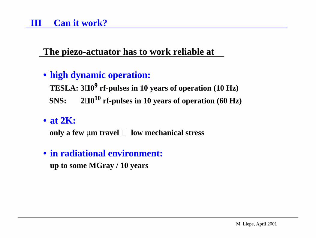
III Can it work?
The piezo-actuator has to work reliable at
• high dynamic operation: TESLA: 3⋅109 rf-pulses in 10 years of operation (10 Hz)
SNS: 2⋅1010 rf-pulses in 10 years of operation (60 Hz)
• at 2K: only a fewµm travel ⇒ low mechanical stress
• in radiational environment: up to some MGray / 10 years

M. Liepe, April 2001
• High Dynamic Operation of a Piezo:Statement by PIEZOMECHANIK:
“This operation mode is characterized by the high acceleration forces act-ing in the piezostack or ring. One popular application in the near future willbe thepiezo triggered Diesel fuel injection, where the control valve ispiezoactuated in theµs-range with maximum stroke.
In the early days of this application, a typical failure mechanism was thegeneration of cracks inside the ceramic, which was the starting point forelectrical break down and short-circuiting of the stacks. ...
An essential contribution to the stack’s reliability under dynamic cycling isthesufficiently high preloading of stacks in the range of 50% to 100% ofthe specified maximum loads.
PIEZOMECHANIK’s actuator are well-known for their excellent stability
under high dynamic operation showing aperformance of more than 1010
cycles. ...”

M. Liepe, April 2001
• Piezo used for Diesel Fuel Injection:
U = -60 to 160 Vsize: 30 x 7 x 7 mm
∆l ≈ 40 µm at room temp.
M. Liepe, April 2001
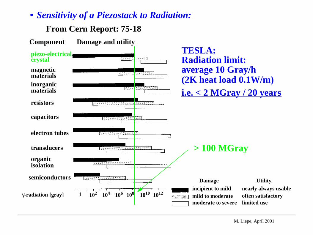
• Sensitivity of a Piezostack to Radiation:
Component Damage and utility
piezo-electricalcrystal
magneticmaterialsinorganicmaterials
resistors
capacitors
electron tubes
transducers
organicisolation
semiconductors
γ-radiation [gray] 1 102 104 106 1010 1012108
From Cern Report: 75-18
TESLA:Radiation limit:average 10 Gray/h(2K heat load 0.1W/m)i.e. < 2 MGray / 20 years
> 100 MGray
Damageincipient to mildmild to moderatemoderate to severe
Utilitynearly always usableoften satisfactorylimited use

M. Liepe, April 2001
• Controllability:
for a linear system:ideal system: same coupling to all modes:
real system:
⇒ K is invertible, if all rows are≠ 0, i.e. if thepiezo is coupling to all modes (and if all rows and columns are different).
If not, place second piezo at aappropriate place.
∆f ω1( )…
∆f ωN( )
K
Vpiezo ω1( )…
Vpiezo ωN( )
=
∆f ω1( )…
∆f ωN( )
K11 … K1N
… … …KN1 … KNN
Vpiezo ω1( )…
Vpiezo ωN( )
=

M. Liepe, April 2001
IV First Results
• used piezo as asensor:⇒ measure piezo-voltage⇒ oscillations (rf-pulses, microphonics)
• tested piezo as anactive element:⇒ apply voltage to piezo⇒ damping / excitation of oscillations⇒ Lorentz-force compensation

M. Liepe, April 2001
• The Piezo as Sensor:
0 0.02 0.04 0.06 0.08 0.1
−0.4
−0.2
0
0.2
0.4
0.6
time [s]
−(pie
zo−v
oltag
e) [
V]
The cavity oscillates between the RF-pulses.
RF-pulse with Lorentz-force detuning
TESLA 9-cell Cavity at 30 MV/m with 10 Hz repetition rate:
- vo
ltage
[V
]mechanical oscillations due to Lorentz-force detuning:

M. Liepe, April 2001
0 0.05 0.1 0.15 0.2 0.25 0.3
−0.6
−0.4
−0.2
0
0.2
0.4
The oscillation is highly repetitive from pulse to pulse.⇒ Same initial detuning at the beginning of the RF pulses!
RF-pulse
TESLA 9-cell Cavity at 30 MV/m with 10 Hz repetition rate:
time [s]
- vo
ltage
[V
]

M. Liepe, April 2001
• Spectrum of the mechanical Oscillations
0 200 400 600 800 100010
−1
100
101
102
mechanical resonances of the cavity
frequency [Hz]
ampl
itude
[arb
. uni
t] due to the RF Pulses (Example):
He-system
pumps

M. Liepe, April 2001
• Frequency Spectrum of Oscillation for 2 Cavities (30MV/m 2Hz)
100 200 300 400 500 6000
1
2
3
4
5
6
7
frequency [Hz]
ampl
itude
[arb
. uni
ts]

M. Liepe, April 2001
• Comparison between the Piezo Signal and the Phase-Variation
0 0.05 0.1 0.15 0.2 0.25−0.5
0
0.5
time [s]
due to Microphonics (Example):
⇒ Clear correlation!⇒ Oscillation can be damped by a piezo-tuner.
phas
e [d
eg]
-6⋅V
piez
o [V
]
cw-operation, open loop

M. Liepe, April 2001
• Microphonics Spectrum:
0 0.05 0.1 0.15 0.2 0.25 0.3−40
−30
−20
−10
0
10
20
30
40
time [s]
detuni
ng [Hz
]de
tuni
ng [H
z]
time [s]
cw-operation of 9-cell cavity
0 200 400 600 800 10000
2
4
6
8
10
12
frequency [Hz]
am
plit
ud
e [
Hz]
pumps,He-system
mechanical resonance
⇒ Only a few frequencies!

0 200 400 600 800 10000
0.005
0.01
0.015
0.02
0.025
frequencypiezo
[Hz]
ampl
itude
[arb
. uni
ts]
M. Liepe, April 2001
• Piezo as an active Element: Excitation of mechanical Modes
2 dominating groups ofmechanical modes

M. Liepe, April 2001
−200
−100
0
100
200
300
400de
tuni
ng [H
z]
0 500 1000 1500 2000time [µs]
fill time 900 µs constant gradient
without compensation
with compensation
“beam on”- time
TTF 9-cell cavity operated in pulsed mode at 23.5 MV/m (TESLA500)• Piezo as an active Element: Lorentz-Detuning Compensation

M. Liepe, April 2001
0 500 1000 1500 2000−5
0
5
10
15
20
25
30
35
40
time [µs]
grad
ient
[MV/
m] ,
pha
se [2
deg
] , d
etun
ing
[20
Hz]
0 500 1000 1500 20000
100
200
300
400
500
600
700
time [µs]
forw
ard
powe
r [kW
]
time [µs]time [µs]
detuning
gradient
phase
power
grad
ient
[ΜV
/m]
detu
ning
[20
Ηz]
phas
e [2
deg]
pow
er [k
W]
• Lorentz-Detuning Compensation:
−200
−100
0
100
200
300
400
detu
ning
[Hz]
0 500 1000 1500 2000time [µs]
fill time 900 µs constant gradient
without compensation
with compensation
“beam on”- time
Simulation:
Measurement:

M. Liepe, April 2001
• Future Plans:
Proof of Principle: Active Lorentz-Detuning Compensation
Investigatemechanical oscil-lations of cavitiesin detail:
measurements,FE-models.
Design, built andtest a prototypepiezo-tuner.
Develop feedfor-ward control.
Test reliability:
Long term oper-ation at 2K andradiation hard-ness of differenttypes of piezoac-tuators.
Reliable, well understood piezoelectric tuner.
workstarted