active damping of torsional modes in turbine-generator shafts · pdf fileactive damping of...
TRANSCRIPT
ACTIVE DAMPING OF TORSIONAL MODES INTURBINE-GENERATOR SHAFTS
A. M. MIRI1, C. SIHLER2, T. ZÖLLER1
(1) Universität Karlsruhe, Institut für Elektroenergiesysteme und Hochspannungstechnik (IEH),Kaiserstr. 12, D-76128 Karlsruhe, Germany E-Mail: [email protected]
(2) Max-Planck-Institut für Plasmaphysik (IPP), EURATOM Association, D-85748 Garching, Germany E-Mail: [email protected]
Abstract − Subsynchronous resonance (SSR) maypossibly occur in turbine-generators with long shafts andlarge inertias constituting a weakly damped mechanicalresonator. Although SSR is most frequently encounteredin power systems with series compensated transmissionlines, electro-mechanical resonances can occur in allkinds of power sytems where synchronous generatorssupply critical loads. Any load causing active powerfluctuations with frequency components in the samerange as the mechanical resonant frequencies of thegenerator shaft assembly can be critical. Evidence forthis statement is supplied by measurements which wereperformed with a 144 MVA and a 220 MVA flywheelgenerator of the IPP experimental power supply.Subsynchronous oscillations and resonances were causedin the shaft assemblies of these synchronous machines bythyristor converter loads supplying an experimentaltokamak. The problems could be solved in applying acompact damper circuit which is connected in parallel tothe dynamic loads. This novel damping method has beencontinuously applied at IPP in more than 3000 dynamicload sequences. Since it has proven to be very efficientand reliable, this paper presents results from numericalinvestigations on applying this active damping method asa countermeasure to SSR in large electrical networks.
1. INTRODUCTION
Torsional resonance problems are most frequentlyencountered in rotor systems with long shafts and largeinertias constituting a weakly damped mechanicalresonator which exhibits a low (subsynchronous)resonance frequency, e. g. 20 – 40 Hz.Subsynchronous resonance (SSR) phenomena inelectric power systems have received great attention inliterature since the first two shaft failures in largeturbo-generators in 1970 and 1971 [1-2]. AlthoughSSR is usually discussed in case of systems withturbine generators and compensated transmission lines,it has been shown that this phenomenon can also occurin other cases, where it can also cause severe damageto machines and equipment [3]. Any load causingactive power fluctuations with frequency componentsin the same range as the mechanical resonantfrequencies of the generator shaft assembly can becritical. Evidence for this statement is supplied by
measurement results from the IPP experimental powersupply, a 500 MVA power supply based on largeflywheel generators.
As a countermeasure to these torsional resonanceproblems a novel feedback controlled circuit wasdeveloped for damping the torsional oscillations [4-5].Connected to the stator winding of a synchronousmachine it produces the same effect as an increasednatural damping for oscillation modes in the rotatingshaft assembly. Therefore, it can be universallyapplied to torsional resonance problems in electricpower systems.
The paper is organized as follows. It starts with adescription of problems with torsional oscillationswhich were experienced in the shaft assemblies offlywheel generators belonging to the experimentalpower supply of ASDEX Upgrade (AUG), Germany’slargest experiment for nuclear fusion research. Aparallel connected circuit developed for damping thesesubsynchronous oscillations is described in Section IIIand application examples are given. In Section IV afurther developed design of the active damping circuitis presented. It is capable to actively damp torsionaloscillations in multi-mass systems, e. g. turbo-generators with large shaft assemblies featuringseveral natural frequencies. The simulation resultspresented show that this damping circuit can even beapplied to classical SSR problems, i. e. systems withturbine generators and compensated transmission lines.The paper ends with a conclusion on the simulationand test results achieved with this novel dampingmethod.
2. TORSIONAL RESONANCE PROBLEMS IN THE IPP POWER SUPPLY
The active damping method for torsionaloscillations in generator shaft assemblies was devisedto solve problems which were experienced in thepower supply of the ASDEX Upgrade (AUG)tokamak. The power and energy for the plasmaexperiments conducted with this experimentaltokamak are supplied by large flywheel generators asshown in Fig. 1, the biggest of which can deliver a

power of 150 megawatts for ten seconds with aflywheel weighing 230 tons. The flywheel generatorssupply high-power thyristor converters. They enable afast control of the DC currents in the magnet coils usedfor magnetic confinement of the plasma in the staticand dynamic case [6]. Because of problems withelectromechanical resonances leading to a damagedcoupling in the shaft assembly of the EZ4 generator,torque measurement and protection systems wereinstalled (see Fig. 2). The torque measuring concept isbased on the anisotropic magnetostrictive effect inferromagnetic materials which is measured by acontactless inductive sensor [7]. A measurement result
showing a resonant excitation of the EZ4 shaft isshown in Fig. 3. More than 100 electromechanicalresonances occuring during plasma experiments wereinvestigated by measurements and partly by numericalinvestigations. Many plasma experiments had to beprematurely terminated by the generator protectionsystem in order to prevent negative effects on thedurability of the shaft assemblies. A torque reductionby a factor of two could be achieved by a solutionbased on changing parameters of the plasma controlsystem [8]. Since this solution adversely affected thedynamic performance of the control system [6], aneffective method of damping the torsional resonancesin the affected rotor shaft systems had to be developed.
3. DESIGN OF THE ACTIVE DAMPING CIRCUITS APPLIED AT IPP
Torsional oscillations in shaft systems can bedescribed by the following n-dimensional differentialequation system:
BuKDJ =++ φφφ &&&
whereφ(t) torsion angles of the shaft;u(t) externally applied torques;J matrix of moments of inertia;
D damping matrix;K stiffness matrix;B input matrix for external torques.
Since the damping matrix of a steel shaft system ismore or less a fixed parameter, the method is based onapplying an additional electrical torque through thestator winding, thus causing the same effect as one (ormore) increased damping coefficient(s). In order todamp only one natural frequency of a shaft assembly,
Fig. 1. Flywheel generator power supply of AUG tokamak
����������
��� ��� ���
������������
�������������
����������������� ������������������
��� ��!"�# $
%�!� ��!�&'$ (')�*+� !',
%!�'(�%�' $ �#
)+�-��+�-.,
��� $ �#�!� �$ #
)/�,
�0�"��
����������
��� ��� ���
������������
�������������
����������������� ������������������
��� ��!"�# $
%�!� ��!�&'$ (')�*+� !',
%!�'(�%�' $ �#
)+�-��+�-.,
��� $ �#�!� �$ #
)/�,
�0�"��
Fig. 2. One of the flywheel generators at IPP with thebig flywheel in the middle and the generator on the right.The arrow shows where the torque sensor was installed
on the rotor shaft system
Fig. 3. Measured output power and torque at the rotor-flywheelcoupling of generator EZ4
Time/s
(1)
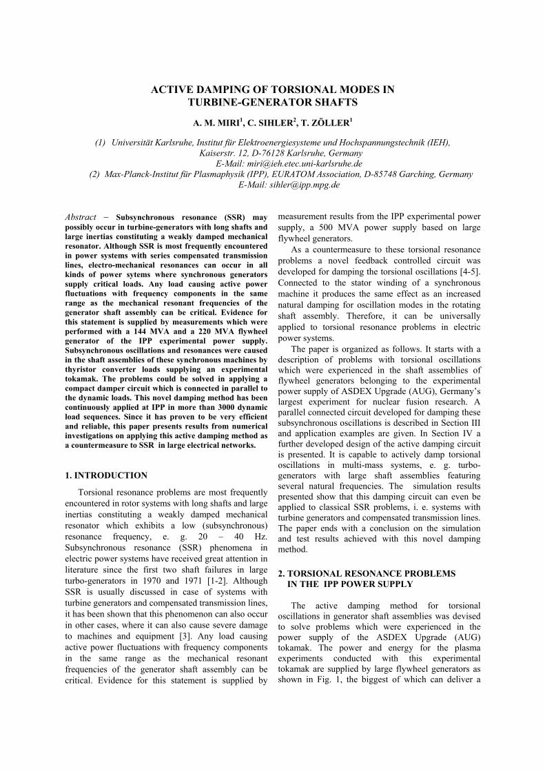
this can be realised in applying an electrical torque incounter-phase to the measured torsional velocity of theshaft as illustrated in the block diagram in Fig. 4. Thetorsional velocity is electronically derived from theexisting torque sensor measurement in the block"Control System for Signal Modification". Below thatblock, the feedback signal is superposed to a staticvalue controlling the DC current in the inductor bymeans of a thyristor converter (current controlled six-pulse bridge circuit). The inductor is used as a bufferstorage for magnetic energy, being loaded andunloaded in counter-phase to the torsional velocity ofthe shaft at the location of the torque sensor. Since theactive damping circuit generates a damping powerPdamp respectively an electromagnetic torque acting onthe rotor with a frequency corresponding to theresonant frequency, this damping method is veryefficient.
Once all control parameters are properly set, sucha parallel connected circuit can be continuously usedto damp one torsional mode of oscillation efficiently.Since the feedback control is based on a torquemeasurement, the damping effect is independent of theexcitation curve (e. g. an electrical or a mechanicaldisturbance, pulse type loads or an active poweroscillation). Different load curves do not requireadjustments or modifications to control parameters ofthe damping module.
Since installation of the first active dampingcircuit in the ASDEX Upgrade power supply, thisdamping method has been continously applied to twodifferent synchronous machines in more than 3000
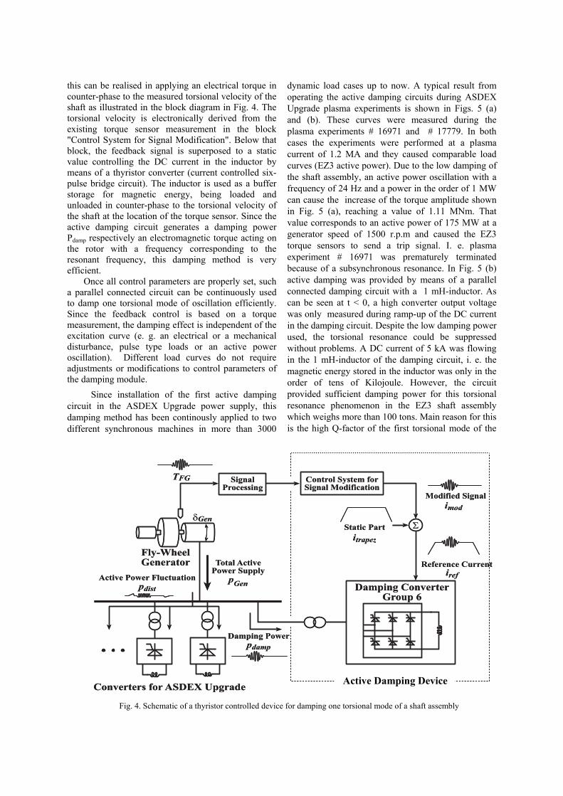
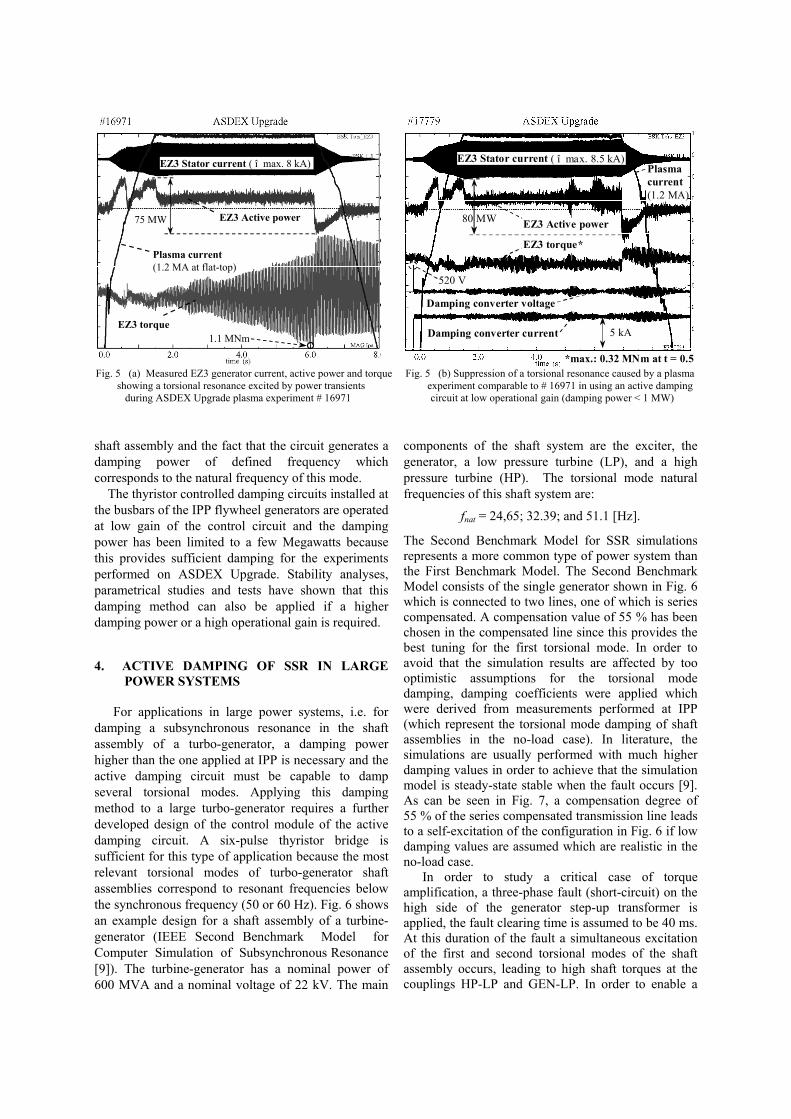
dynamic load cases up to now. A typical result fromoperating the active damping circuits during ASDEXUpgrade plasma experiments is shown in Figs. 5 (a)and (b). These curves were measured during theplasma experiments # 16971 and # 17779. In bothcases the experiments were performed at a plasmacurrent of 1.2 MA and they caused comparable loadcurves (EZ3 active power). Due to the low damping ofthe shaft assembly, an active power oscillation with afrequency of 24 Hz and a power in the order of 1 MWcan cause the increase of the torque amplitude shownin Fig. 5 (a), reaching a value of 1.11 MNm. Thatvalue corresponds to an active power of 175 MW at agenerator speed of 1500 r.p.m and caused the EZ3torque sensors to send a trip signal. I. e. plasmaexperiment # 16971 was prematurely terminatedbecause of a subsynchronous resonance. In Fig. 5 (b)active damping was provided by means of a parallelconnected damping circuit with a 1 mH-inductor. Ascan be seen at t < 0, a high converter output voltagewas only measured during ramp-up of the DC currentin the damping circuit. Despite the low damping powerused, the torsional resonance could be suppressedwithout problems. A DC current of 5 kA was flowingin the 1 mH-inductor of the damping circuit, i. e. themagnetic energy stored in the inductor was only in theorder of tens of Kilojoule. However, the circuitprovided sufficient damping power for this torsionalresonance phenomenon in the EZ3 shaft assemblywhich weighs more than 100 tons. Main reason for thisis the high Q-factor of the first torsional mode of the
�3$ 4 �%�1 �5!.3$.�$ �#�����
� #�!%�3 '' #
+�#4 $ '�6������������
���
��
+�#$�!��&'$ (�6�� #�!�"�� 6 3�$ �#
"�� 6 ��� #�!
��(� #�+�#4 $ 2�.��0
��(� #�%�1 �����
��$�!��3$ 4 %�1 ��.��!&
��
5!&*78 !2 # �$�
�� �
: 6 #3 �+. #$���
�$�$ 3�%�$������
�
�3$ 4 �%�1 �5!.3$.�$ �#�����
� #�!%�3 '' #
+�#4 $ '�6������������
���
��
+�#$�!��&'$ (�6�� #�!�"�� 6 3�$ �#
"�� 6 ��� #�!
��(� #�+�#4 $ 2�.��0
��(� #�%�1 �����
��$�!��3$ 4 %�1 ��.��!&
��
5!&*78 !2 # �$�
�� �
: 6 #3 �+. #$���
�$�$ 3�%�$������
�
Active Damping Facility
Fig. 4. Schematic of a thyristor controlled device for damping one torsional mode of a shaft assembly
Active Damping Device
shaft assembly and the fact that the circuit generates adamping power of defined frequency whichcorresponds to the natural frequency of this mode.
The thyristor controlled damping circuits installed atthe busbars of the IPP flywheel generators are operatedat low gain of the control circuit and the dampingpower has been limited to a few Megawatts becausethis provides sufficient damping for the experimentsperformed on ASDEX Upgrade. Stability analyses,parametrical studies and tests have shown that thisdamping method can also be applied if a higherdamping power or a high operational gain is required.
4. ACTIVE DAMPING OF SSR IN LARGE POWER SYSTEMS
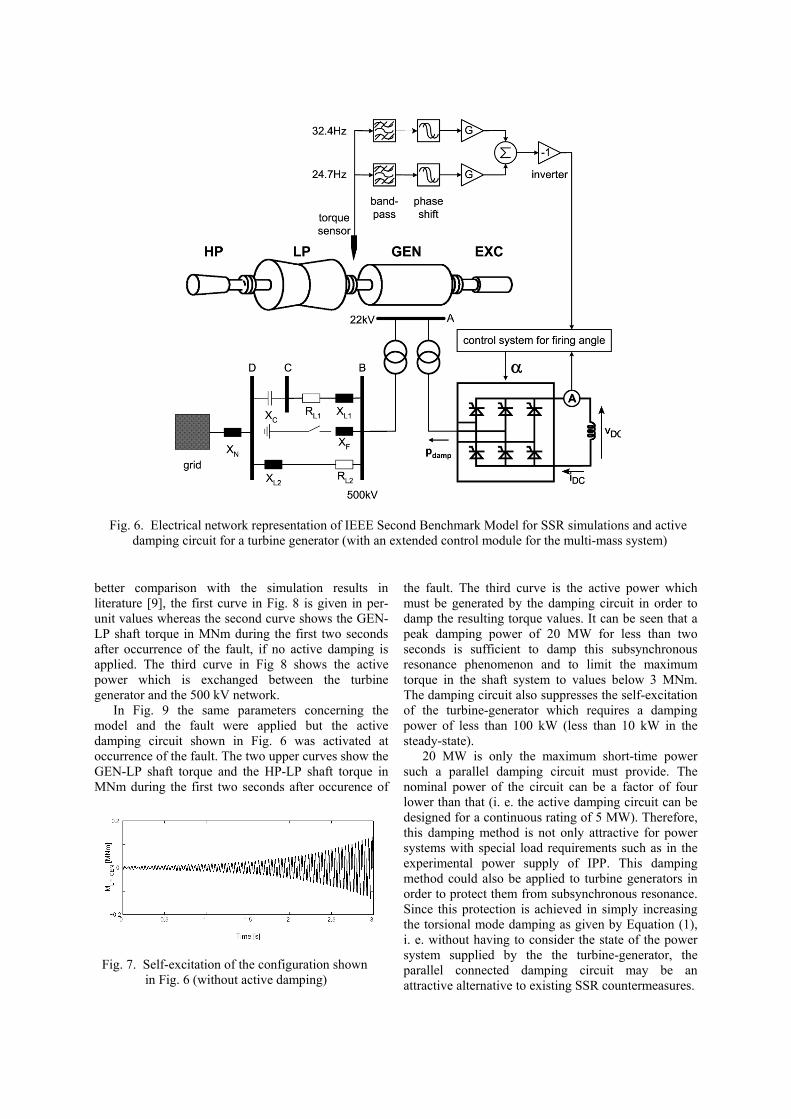
For applications in large power systems, i.e. fordamping a subsynchronous resonance in the shaftassembly of a turbo-generator, a damping powerhigher than the one applied at IPP is necessary and theactive damping circuit must be capable to dampseveral torsional modes. Applying this dampingmethod to a large turbo-generator requires a furtherdeveloped design of the control module of the activedamping circuit. A six-pulse thyristor bridge issufficient for this type of application because the mostrelevant torsional modes of turbo-generator shaftassemblies correspond to resonant frequencies belowthe synchronous frequency (50 or 60 Hz). Fig. 6 showsan example design for a shaft assembly of a turbine-generator (IEEE Second Benchmark Model forComputer Simulation of Subsynchronous Resonance[9]). The turbine-generator has a nominal power of600 MVA and a nominal voltage of 22 kV. The main
components of the shaft system are the exciter, thegenerator, a low pressure turbine (LP), and a highpressure turbine (HP). The torsional mode naturalfrequencies of this shaft system are:
fnat = 24,65; 32.39; and 51.1 [Hz].
The Second Benchmark Model for SSR simulationsrepresents a more common type of power system thanthe First Benchmark Model. The Second BenchmarkModel consists of the single generator shown in Fig. 6which is connected to two lines, one of which is seriescompensated. A compensation value of 55 % has beenchosen in the compensated line since this provides thebest tuning for the first torsional mode. In order toavoid that the simulation results are affected by toooptimistic assumptions for the torsional modedamping, damping coefficients were applied whichwere derived from measurements performed at IPP(which represent the torsional mode damping of shaftassemblies in the no-load case). In literature, thesimulations are usually performed with much higherdamping values in order to achieve that the simulationmodel is steady-state stable when the fault occurs [9].As can be seen in Fig. 7, a compensation degree of55 % of the series compensated transmission line leadsto a self-excitation of the configuration in Fig. 6 if lowdamping values are assumed which are realistic in theno-load case.
In order to study a critical case of torqueamplification, a three-phase fault (short-circuit) on thehigh side of the generator step-up transformer isapplied, the fault clearing time is assumed to be 40 ms.At this duration of the fault a simultaneous excitationof the first and second torsional modes of the shaftassembly occurs, leading to high shaft torques at thecouplings HP-LP and GEN-LP. In order to enable a
Plasma current(1.2 MA at flat-top)
EZ3 Active power75 MW
EZ3 Stator current ( î max. 8 kA)
EZ3 torque1.1 MNm
Plasmacurrent(1.2 MA)
EZ3 Active power80 MW
EZ3 Stator current ( î max. 8.5 kA)
EZ3 torque*
Damping converter voltage
Damping converter current
520 V
5 kA
*max.: 0.32 MNm at t = 0.5 Fig. 5 (a) Measured EZ3 generator current, active power and torque Fig. 5 (b) Suppression of a torsional resonance caused by a plasma showing a torsional resonance excited by power transients experiment comparable to # 16971 in using an active damping during ASDEX Upgrade plasma experiment # 16971 circuit at low operational gain (damping power < 1 MW)
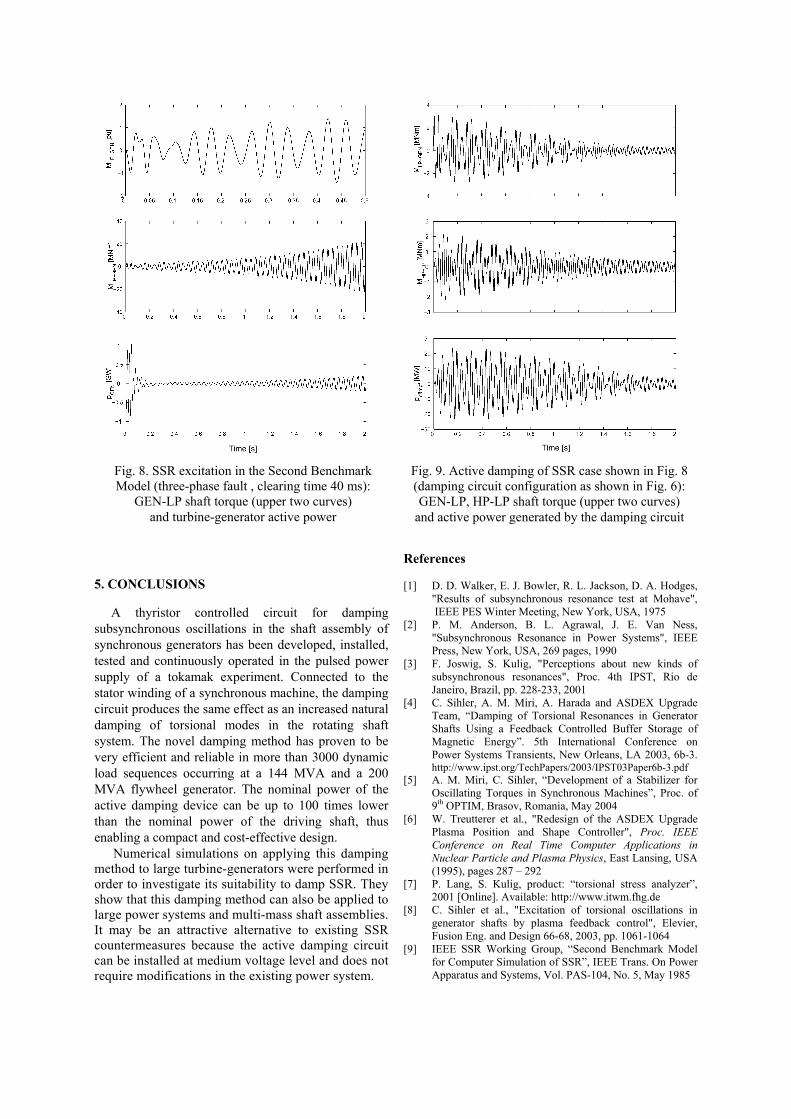
better comparison with the simulation results inliterature [9], the first curve in Fig. 8 is given in per-unit values whereas the second curve shows the GEN-LP shaft torque in MNm during the first two secondsafter occurrence of the fault, if no active damping isapplied. The third curve in Fig 8 shows the activepower which is exchanged between the turbinegenerator and the 500 kV network.
In Fig. 9 the same parameters concerning themodel and the fault were applied but the activedamping circuit shown in Fig. 6 was activated atoccurrence of the fault. The two upper curves show theGEN-LP shaft torque and the HP-LP shaft torque inMNm during the first two seconds after occurence of
the fault. The third curve is the active power whichmust be generated by the damping circuit in order todamp the resulting torque values. It can be seen that apeak damping power of 20 MW for less than twoseconds is sufficient to damp this subsynchronousresonance phenomenon and to limit the maximumtorque in the shaft system to values below 3 MNm.The damping circuit also suppresses the self-excitationof the turbine-generator which requires a dampingpower of less than 100 kW (less than 10 kW in thesteady-state).
20 MW is only the maximum short-time powersuch a parallel damping circuit must provide. Thenominal power of the circuit can be a factor of fourlower than that (i. e. the active damping circuit can bedesigned for a continuous rating of 5 MW). Therefore,this damping method is not only attractive for powersystems with special load requirements such as in theexperimental power supply of IPP. This dampingmethod could also be applied to turbine generators inorder to protect them from subsynchronous resonance.Since this protection is achieved in simply increasingthe torsional mode damping as given by Equation (1),i. e. without having to consider the state of the powersystem supplied by the the turbine-generator, theparallel connected damping circuit may be anattractive alternative to existing SSR countermeasures.
Fig. 6. Electrical network representation of IEEE Second Benchmark Model for SSR simulations and active damping circuit for a turbine generator (with an extended control module for the multi-mass system)
Fig. 7. Self-excitation of the configuration shown in Fig. 6 (without active damping)
5. CONCLUSIONS
A thyristor controlled circuit for dampingsubsynchronous oscillations in the shaft assembly ofsynchronous generators has been developed, installed,tested and continuously operated in the pulsed powersupply of a tokamak experiment. Connected to thestator winding of a synchronous machine, the dampingcircuit produces the same effect as an increased naturaldamping of torsional modes in the rotating shaftsystem. The novel damping method has proven to bevery efficient and reliable in more than 3000 dynamicload sequences occurring at a 144 MVA and a 200MVA flywheel generator. The nominal power of theactive damping device can be up to 100 times lowerthan the nominal power of the driving shaft, thusenabling a compact and cost-effective design. Numerical simulations on applying this dampingmethod to large turbine-generators were performed inorder to investigate its suitability to damp SSR. Theyshow that this damping method can also be applied tolarge power systems and multi-mass shaft assemblies.It may be an attractive alternative to existing SSRcountermeasures because the active damping circuitcan be installed at medium voltage level and does notrequire modifications in the existing power system.
References
[1] D. D. Walker, E. J. Bowler, R. L. Jackson, D. A. Hodges,"Results of subsynchronous resonance test at Mohave", IEEE PES Winter Meeting, New York, USA, 1975
[2] P. M. Anderson, B. L. Agrawal, J. E. Van Ness,"Subsynchronous Resonance in Power Systems", IEEEPress, New York, USA, 269 pages, 1990
[3] F. Joswig, S. Kulig, "Perceptions about new kinds ofsubsynchronous resonances", Proc. 4th IPST, Rio deJaneiro, Brazil, pp. 228-233, 2001
[4] C. Sihler, A. M. Miri, A. Harada and ASDEX UpgradeTeam, “Damping of Torsional Resonances in GeneratorShafts Using a Feedback Controlled Buffer Storage ofMagnetic Energy”. 5th International Conference onPower Systems Transients, New Orleans, LA 2003, 6b-3.http://www.ipst.org/TechPapers/2003/IPST03Paper6b-3.pdf
[5] A. M. Miri, C. Sihler, “Development of a Stabilizer forOscillating Torques in Synchronous Machines”, Proc. of9th OPTIM, Brasov, Romania, May 2004
[6] W. Treutterer et al., "Redesign of the ASDEX UpgradePlasma Position and Shape Controller", Proc. IEEEConference on Real Time Computer Applications inNuclear Particle and Plasma Physics, East Lansing, USA(1995), pages 287 – 292
[7] P. Lang, S. Kulig, product: “torsional stress analyzer”,2001 [Online]. Available: http://www.itwm.fhg.de
[8] C. Sihler et al., "Excitation of torsional oscillations ingenerator shafts by plasma feedback control", Elevier,Fusion Eng. and Design 66-68, 2003, pp. 1061-1064
[9] IEEE SSR Working Group, “Second Benchmark Modelfor Computer Simulation of SSR”, IEEE Trans. On PowerApparatus and Systems, Vol. PAS-104, No. 5, May 1985
Fig. 8. SSR excitation in the Second BenchmarkModel (three-phase fault , clearing time 40 ms):
GEN-LP shaft torque (upper two curves)and turbine-generator active power
Fig. 9. Active damping of SSR case shown in Fig. 8(damping circuit configuration as shown in Fig. 6):GEN-LP, HP-LP shaft torque (upper two curves)
and active power generated by the damping circuit