active filters
TRANSCRIPT

Active Filters

IntroductionIntroduction
Filters are circuits that are capable of passing signals within a band of frequencies while rejecting or blocking signals of frequencies outside this band.
This property of filters is also called “frequency selectivity”.

Types of Filters
There are two broad categories of filters: An analog filter processes continuous-time signals A digital filter processes discrete-time signals.
The analog or digital filters can be subdivided into four categories: Lowpass Filters Highpass Filters Bandstop Filters Bandpass Filters

Ideal Filters
Passband Stopband Stopband Passband
Passband PassbandStopband
Lowpass Filter Highpass Filter
Bandstop Filter
PassbandStopband Stopband
Bandpass Filter
M(ω)
M(ω)
ω ω
ω ω
ω c ω c
ω c1ω c1
ω c2ω c2

Analog Filter Responses
H(f)
ffc
0
H(f)
ffc
0
Ideal “brick wall” filter Practical filter
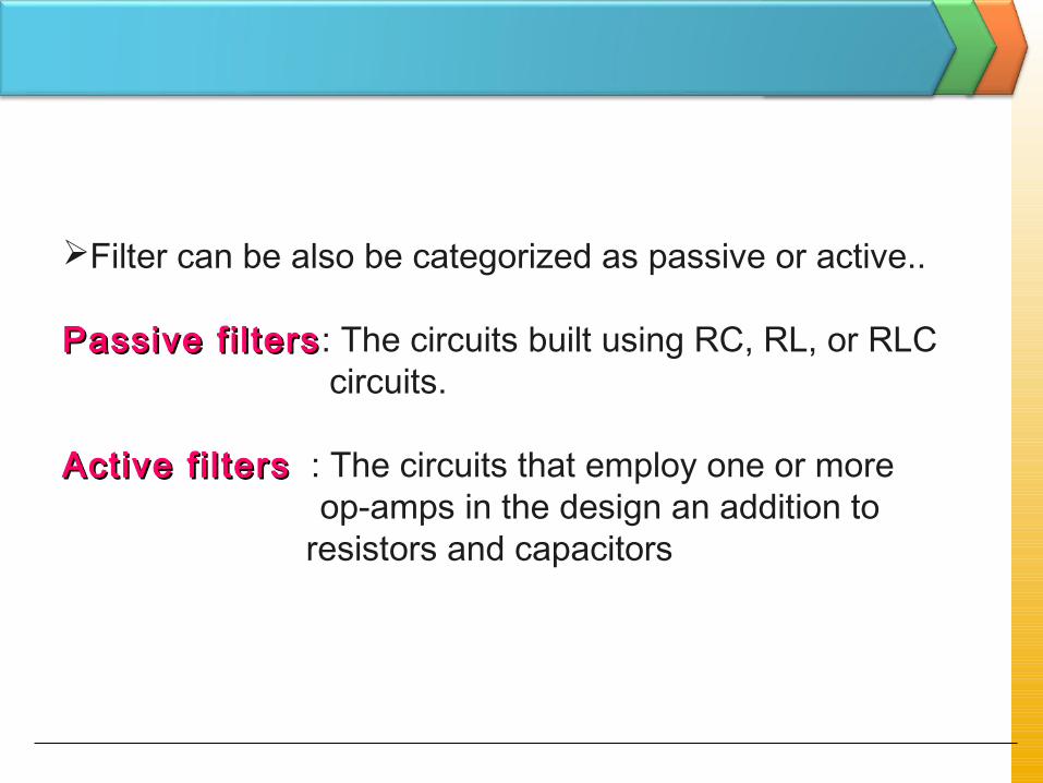
Filter can be also be categorized as passive or active..
Passive f i l tersPassive f i l ters: The circuits built using RC, RL, or RLC circuits.
Active f i l tersActive f i l ters : The circuits that employ one or more op-amps in the design an addition to
resistors and capacitors

Passive filtersPassive filters use resistors, capacitors, and inductors
(RLC networks).
To minimize distortion in the filter characteristic, it is desirable to use inductors with high quality factors
practical inductors includes a series resistance. They are particularly non-ideal They are bulky and expensive

Active filters overcome these drawbacks and are realized using resistors, capacitors, and active devices (usually op-amps) which can all be integrated:
Active filters replace inductors using op-amp based equivalent circuits.

Advantages
Advantages of active RC filters include: reduced size and weight increased reliability and improved performance simpler design than for passive filters and can realize a wider
range of functions as well as providing voltage gain in large quantities, the cost of an IC is less than its passive
counterpart

DisadvantagesActive RC filters also have some disadvantages:
limited bandwidth of active devices limits the highest attainable frequency (passive RLC filters can be used up to 500 MHz)
require power supplies (unlike passive filters) increased sensitivity to variations in circuit parameters
caused by environmental changes compared to passive filters
For many applications, particularly in voice and data communications, the economic and performance advantages of active RC filters far outweigh their disadvantages.
Bode Plots
Bode plots are important when considering the frequency response characteristics of amplifiers.
They plot the magnitude or phase of a transfer function in dB versus frequency.

Bode plots use a logarithmic scale for frequency.
where a decade is defined as a range of frequencies where the highest and lowest frequencies differ by a factor of 10.
10 20 30 40 50 60 70 80 90 100 200
One decade

The decibel (dB)
Two levels of power can be compared using aunit of measure called the bel.
The decibel is defined as:
1 bel = 10 decibels (dB)
1
210logP
PB =

A common dB term is the half power pointwhich is the dB value when the P2 is one-half P1.
1
210log10P
PdB =
dBdB 301.32
1log10 10 −≈−=

15
Decibel (dB) By Definition:
=
1
210log10P
PdB
(1) Power Gain in dB :
=in
o
p P
PdBA
10log10)(
=in
in
P
PdB
10log100
=−in
in
P
PdB 2
1
log10310
=+
in
in
P
PdB
2log103
10
Pin Pout
(2) Voltage Gain in dB: (P=V2/R)
vin vout
=in
o
v v
vdBA
10log20)(
=in
in
v
vdB
10log200
=−in
in
v
vdB 2
1
log20610
=+in
in
v
vdB
2log206
10

16
Cascaded System
Av1 Av2 Av3x10 x10x10
vin vout
20dB 20dB 20dB
321 vvvvAAAA ××=
310101010 =××=vA
( )32110
log20)(vvvvAAAdBA ××=
( ) ( ) ( )310210110
log20log20log20)(vvvvAAAdBA ++=
( ) ( ) ( )dBAdBAdBAdBAvvvv 321
)( ++=
dBdBdBdBAv
202020)( ++=
dBdBAv
60)( =( ) dB2010log20
10=
( ) dB6010log20 3
10=

Poles & Zeros of the transfer functionpole—value of s where the denominator goes to
zero.zero—value of s where the numerator goes to zero.

Actual response
Vo
A low-pass filterlow-pass filter is a filter that passes frequencies from 0Hz to critical frequency, fc and significantly attenuates all other frequencies.
Ideal response
Ideally, the response drops abruptly at the critical frequency, fH
roll-off rateroll-off rate

StopbandStopband is the range of frequencies that have the most attenuation.
Crit ical frequencyCrit ical frequency, ff cc, (also called the cutoff frequency) defines the end of the passband and normally specified at the point where the response drops – 3 dB (70.7%) from the passband response.
PassbandPassband of a filter is the range of frequencies that are allowed to pass through the filter with minimum attenuation (usually defined as less than -3 dB of attenuation).
Transition regionTransition region shows the area where the fall-off occurs.
roll-off rateroll-off rate

At low frequencies, XC is very high and the capacitor circuit can be considered as open circuit. Under this condition, Vo = Vin or AV = 1 (unity).
At very high frequencies, XC is very low and the Vo is small as compared with Vin. Hence the gain falls and drops off gradually as the frequency is increased.
Vo

The bandwidthbandwidth of an idealideal low-pass filter is equal to ffcc:
cfBW =
The critical frequency of a low-pass RC filter occurs when
XX CC = R = R and can be calculated using the formula below:
RCfc π2
1=

A high-pass filterhigh-pass filter is a filter that significantly attenuates or rejects all frequencies below fc and passes all frequencies above fc.
The passband of a high-pass filter is all frequencies above the critical frequency..
Vo
Actual response Ideal response
Ideally, the response rises abruptly at the critical frequency, fL

The critical frequency of a high-pass RC filter occurs when
XX CC = R = R and can be calculated using the formula below:
RCfc π2
1=

A band-pass filterband-pass filter passes all signals lying within a band between a lower-frequency limitlower-frequency limit and upper-frequency limitupper-frequency limit and essentially rejects all other frequencies that are outside this specified band.
Actual response Ideal response

The bandwidth (BW)bandwidth (BW) is defined as the differencedifference between the upper critical frequency (fupper critical frequency (fc2c2)) and the lower critical lower critical frequency (ffrequency (fc1c1)).
12 cc ffBW −=

21 cco fff =
The frequency about which the pass band is centered is called the center frequencycenter frequency, ff oo and defined as the geometric mean of the critical frequencies.

Band-stop filterBand-stop filter is a filter which its operation is oppositeopposite to that of the band-pass filter because the frequencies withinwithin the bandwidth are rejectedrejected, and the frequencies above ffc1c1 and ffc2c2 are passedpassed.
Actual response
For the band-stop filter, the bandwidthbandwidth is a band of frequencies between the 3 dB points, just as in the case of the band-pass filter response.
Ideal response

RCfc π2
1=
cXR =
Figure below shows the basic Low-Pass filter circuit
CfR
cπ21=
CR
cω1=
At critical frequency,
Resistance = Capacitance
So, critical frequency ;

RCfc π2
1=
cXR =
Figure below shows the basic High-Pass filter circuit :
CfR
cπ21=
CR
cω1=
At critical frequency,
Resistance = Capacitance
So, critical frequency ;

Single-Pole Passive Filter
First order low pass filterCut-off frequency = 1/RC rad/sProblem : Any load (or source) impedance will
change frequency response.
vin voutC
R
RCs
RC
sCR
sCR
sC
ZR
Z
v
v
C
C
in
out
/1
/1
1
1
/1
/1
+=
+=
+=
+=
Ref:080222HKN EE3110 Active Filter (Part 1)31
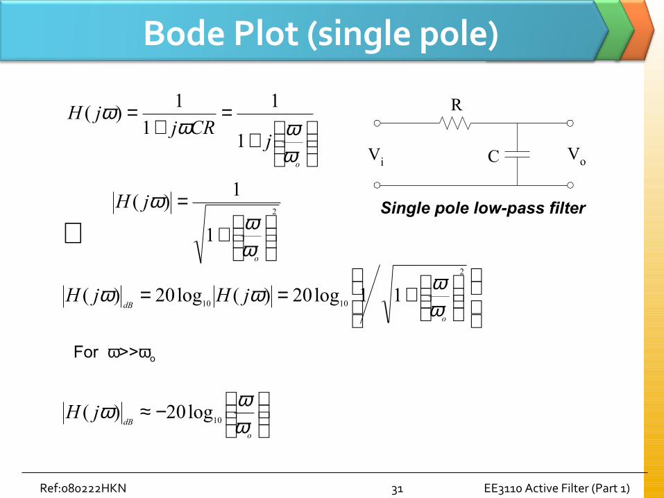
Bode Plot (single pole)
+=
+=
o
jCRj
jH
ωωω
ω1
11
1)(
2
1
1)(
+
=
o
jH
ωω
ω
+==2
101011log20)(log20)(
o
dBjHjH
ωωωω
⇒
−≈o
dBjH
ωωω
10log20)(
For ω>>ωo
R
C VoVi
Single pole low-pass filter

32
dBjH )( ω
(log)ωx
ωx
ω2 xω10
6dB
20dB slope
-6dB/octave-20dB/decade
−≈
o
jHωωω 10log20)(
For octave apart,1
2=o
ωω dBjH 6)( −≈ω
For decade apart,
1
10=oω
ω dBjH 20)( −≈ω

Single-Pole Active Low-Pass Filter
Same frequency response as passive filter.Buffer amplifier does not load RC network.Output impedance is now zero.
vin vout
CR

Single-pole active low-pass filter and response curve.
This filter provides a roll-off rate of -20 dB/decade above the critical frequency.

The op-amp in single-pole filter is connected as a noninverting amplifier with the closed-loop voltage gain in the passband is set by the values of R1 and R2 :
12
1)( +=R
RA NIcl
The critical frequency of the single-pole filter is :
RCfc π2
1=

The critical frequencycritical frequency, ffcc is determined by the values of R and C in the frequency-selective RC circuit.
Each RCRC set of filter components represents a polepole.
Greater roll-off ratesGreater roll-off rates can be achieved with more polesmore poles.
Each pole represents a -20dB/decade-20dB/decade increase in roll-off.
One-pole (first-order) low-pass filter.

In high-pass filters, the roles of the capacitorcapacitor and resistorresistor are reversedreversed in the RC circuits as shown from Figure (a). The negative feedback circuit is the same as for the low-pass filters.
Figure (b) shows a high-pass active filter with a -20dB/decade roll-off
Single-pole active high-pass filter and response curve.

The op-amp in single-pole filter is connected as a noninverting amplifier with the closed-loop voltage gain in the passband is set by the values of R1 and R2 :
12
1)( +=R
RA NIcl
The critical frequency of the single-pole filter is :
RCfc π2
1=

The number of poles determines the roll-off rate of the filter. A Butterworth response produces -20dB/decade/poleThis means that: One-pole (first-order)One-pole (first-order) filter has a roll-off of -20 dB/decade Two-pole (second-order)Two-pole (second-order) filter has a roll-off of -40 dB/decade Three-pole (third-order)Three-pole (third-order) filter has a roll-off of -60 dB/decade

The number of filter poles can be increased by cascadingcascading. To obtain a filter with three poles, cascade a two-pole with one-pole filters.
Three-pole (third-order) low/high pass filter.

41
Two-Stage Band-Pass Filter
R2 R1
vin
C1
C2
Rf1
Rf2
C4 C3
R3
R4
+V
-V
vout
Rf3
Rf4
+
-
+
-
+V
-V
Stage 1Two-pole low-pass
Stage 2Two-pole high-pass
BW
f1 f2
f
Av
Stage 2response
Stage 1response
fo
BW = f2 – f1
Q = f0 / BW

42
Band-Stop (Notch) FilterThe notch filter is designed to block all frequencies that fall within its bandwidth. The circuit is made up of a high pass filter, a low-pass filter and a summing amplifier. The summing amplifier will have an output that is equal to the sum of the filter output voltages.
f 1
f 2
v in v out
Low passfilter
High passfilter
Summingamplifier
Σ
-3dB{
f
f2f1
Av(dB)
low-pass high-pass
Block diagram Frequency response

43
Notch filter

44
Transfer function H(jω)
TransferFunction
)( ωjHVoVi
)(
)()(
ωωωjV
jVjH
i
o=
)Im()Re( HjHH +=
22 )Im()Re( HHH +=

45
Frequency transfer function of filter H(jω)
HL
HL
o
o
o
o
ffffjH
fffjH
ffjH
ffjH
ffjH
ffjH
><=
<<=
>=
<=
>=
<=
and 0)(
1)(
Filter Pass-Band (III)
1)(
0)(
Filter Pass-High (II)
0)(
1)(
Filter Pass-Low (I)
ω
ω
ω
ω
ω
ω
response phase specific a has
allfor 1)(
Filter shift)-phase(or Pass-All (V)
and 1)(
0)(
Filter (Notch) Stop-Band (IV)
fjH
ffffjH
fffjH
HL
HL
=
><=
<<=
ω
ω
ω

Advantages of active filters over passive filters (R, L, and C elements only):
1. By containing the op-amp, active filters can be designed to provide required gain, and hence no signal attenuationno signal attenuation as the signal passes through the filter.
2. No loading problemNo loading problem, due to the high input impedance of the op-amp prevents excessive loading of the driving source, and the low output impedance of the op-amp prevents the filter from being affected by the load that it is driving.
3. Easy to adjust over a wide frequency rangeEasy to adjust over a wide frequency range without altering the desired response.