active metal brazing and characterization of brazed joints in
TRANSCRIPT
Materials Science and Engineering A (2005) in press
Active Metal Brazing and Characterization of Brazed Joints in Titanium to Carbon-Carbon Composites
M. Singh and T.P. Shpargel QSS Group, Inc.,
NASA Glenn Research Center Cleveland, OH 44135
G. N. Morscher Ohio Aerospace Institute
NASA Glenn Research Center Cleveland, OH 44135
R. Asthana Technology Department
University of Wisconsin-Stout Menomonie, WI 54751
ABSTRACT The Ti-metal/C-C composite joints were formed by reactive brazing with three commercial
brazes, namely, Cu-ABA, TiCuNi, and TiCuSil. The joint microstructures were examined using
optical microscopy and scanning electron microscopy (SEM) coupled with energy dispersive
spectrometry (EDS). The results of the microstructure analysis indicate solute redistribution
across the joint and possible metallurgical bond formation via interdiffusion, which led to good
wetting and spreading. A tube-on-plate tensile test was used to evaluate joint strength of Ti-
tube/C-C composite joints. The load-carrying ability was greatest for the Cu-ABA braze joint
structures. This system appeared to have the best braze spreading which resulted in a larger
braze/C-C composite bonded area compared to the other two braze materials. Also, joint load-
carrying ability was found to be higher for joint structures where the fiber tows in the outer ply
of the C-C composite were aligned perpendicular to the tube axis when compared to the case
where fiber tows were aligned parallel to the tube axis.
https://ntrs.nasa.gov/search.jsp?R=20060005030 2018-12-27T03:40:57+00:00Z
2
1. INTRODUCTION
Carbon-carbon (C-C) composites are extensively used for the nose cap and leading edges of
the space shuttle, rocket nozzles exit cones and heat shield for ballistic missiles [1]. For the space
exploration systems, high conductivity C-C composites have been developed for applications in
lightweight radiators and recuperators of the thermal management systems and for spacecraft
structures. Most such applications will require joining C-C to metals. Robust assembly and
integration technologies will, therefore, play an essential role in the development and
manufacture of parts using novel and conventional carbon-base materials [2-4]. Carbon-carbon
has been brazed using Ag, Au and Cu-base filler metals for moderate use temperatures, and Zr
and Hf metals, and HfB2 and MoSi2 powders for very high use temperatures [5-7].
In this paper, three commercial active metal brazes (Cu-ABA, TiCuNi, and TiCuSil) were used
to create C-C/Ti joints. The microstructure and composition of the brazed joints were examined
by optical and scanning electron microscopy (SEM) coupled with EDS. The effect of braze
composition and processing conditions on the interfacial microstructure and composition of the
joint regions is presented in light of the wetting and spreading of reactive brazes. Joint strength
was characterized to examine the effect of the bonded area and the orientation of the C fibers in
the outer ply on the strength.
2. EXPERIMENTAL PROCEDURE
The carbon-carbon composites used in this study were obtained from C-C Advanced
Technologies, Inc. (C-CAT) Fort Worth, TX. These composites were made from T-300 C fibers
and resin-derived carbon matrix. The composite panels were sliced into 2.54 cm x 1.25 cm x
0.25 cm pieces. Commercially pure Ti plates from Titanium Metals Corporation (TIMET), MO,
were also cut into slices of the same size, and joined to C-C using intervening braze foils. The
following commercial brazes obtained from Morgan Advanced Ceramics, Inc., CA, were used
for joining C-C composites to Ti: Cu-ABA, TiCuNi, and TiCuSil. The composition, and physical
and mechanical characteristics of these brazes are summarized in Table 1. The braze foil
thickness was ~50 µm. All the materials were ultrasonically cleaned in acetone for 10 min. prior
3
to their use. The braze foil, cut to the size of Ti and C-C plates, was sandwiched between them,
and a normal load of 0.30 N was applied to the assembly to hold them together. The assembly
was heated to the brazing temperature under vacuum, isothermally held for 5 min., and then
cooled to room temperature. The brazed samples were cut, mounted in epoxy, polished, and
examined using optical and scanning electron microscopy (SEM) coupled with energy dispersive
x-ray spectroscopy (EDS).
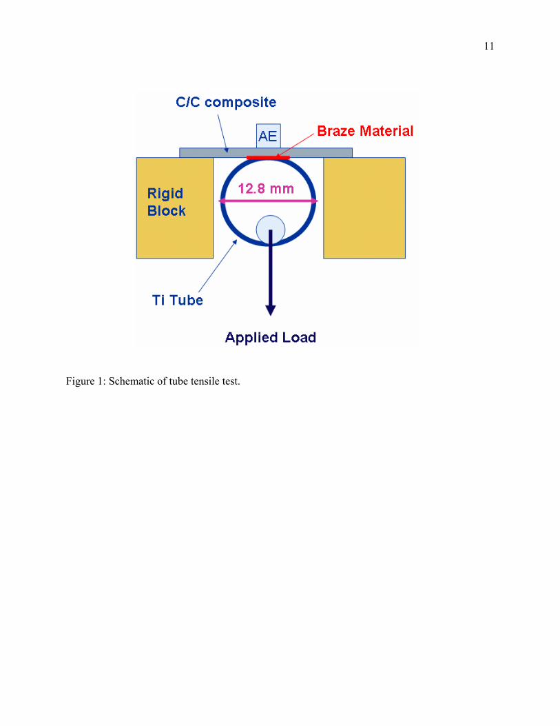
For mechanical testing, a “tube tensile test” was developed [8] to evaluate the effectiveness
of the three braze approaches for tube/plate braze applications. C-C composite pieces, 2.54 cm x
1.25 cm x 0.25 cm, were brazed to 1.25 cm diameter Ti tubes. The tensile test (Figure 1)
consisted of mounting the flat plate on a rigid bar and pulling the tube in tension with a universal
testing machine (Instron 4502, Canton, MA). The peak load corresponded to the load-carrying
ability of the joint. The fracture surface was examined to determine the fracture location and
nature and extent of bonding.
3. RESULTS AND DISCUSSION
3.1 Interface Microstructure
Figures 2 through 7 display the interface microstructure of the joints made using the three
braze materials. Both low- and high-magnification views of the C-C/braze interface for each of
the braze materials indicate an intimate contact between the carbon and the braze. The interfaces
are free of commonly-found structural defects such as microvoids and porosity. An interfacial
interphase appears to have preferentially precipitated on the carbon surface in all the cases (Figs.
3, 5 & 7). The EDS analysis across the interface regions shows evidence of solute redistribution
during brazing. High Ti concentrations were detected at the interface in C-C/TiCuNi (Fig. 5a)
and C-C/TiCuSil (Fig. 7a) joints, suggesting possible formation of a Ti-rich interphase, such as
TiC1-x, which bonds well to both the carbon and the braze. At the braze/Ti interface, some
dissolution of the metal in the molten braze appears to have occurred, leading to near-interfacial
changes in the composition. Overall, the interfaces appear to be microstructurally sound, and
well-bonded due to interdiffusion of solutes and the formation of secondary phases.
4
The formation of TiC in Ti-containing brazes in contact with carbon is thermodynamically
favorable. The Gibb’s free energy change for TiC formation from the reaction Ti+C TiC in the
temperature range 920-1050ºC is -174 to 169 kJ, which indicates that TiC formation is highly
likely. Thermodynamic calculations [9,10] also show that sub-stoichiometric carbides such as
TiC0.95, TiC0.91, TiC0.80, TiC0.70, TiC0.60 and TiC0.48 could form from Cu alloys in which the
activity of Ti is greater than 0.1. As the solubility of Ti in Cu at the brazing temperatures of 920-
1050° C is high, its activity coefficient may be large enough to cause the formation of these
carbides. With reference to the Cu-ABA braze, it should be noted that it contains Si in addition
to Ti, and both silicon carbide and titanium carbide could form from the reaction of Si and Ti
with carbon. The Gibb’s free energy change for SiC formation (Si+C SiC) in the temperature
range 920 to 1050°C is -62.4 to -61.1 kJ, which suggests that SiC formation during brazing is
thermodynamically possible.
3.2 Braze Spreading The interface microstructures presented in Figs. 2-7 show that the Ti-metal/braze/C-C joints
are free of interfacial micro defects, and exhibit excellent physical contact and good
metallurgical bonding. The literature data compiled in Table 2 and Fig. 8(a) show that Ti
additions to Sn, Ag, Cu, and CuSn alloys sharply decrease the contact angle, θ, and promote
braze spreading on carbon. Usually, short brazing times suffice for maximum spread; for
example, θ approaches 0° in 5 min. for Cu-12%Ti melt in contact with vitreous C [11]. Thus,
pure Cu and Ag do not wet graphite (θ ∼ 137°-140°), but the addition of Ti [9,11,12] and/or Si
[13] improves the wetting through the formation of carbides TiC and SiC at the interface. One of
our brazes, Copper-ABA, contained Si besides Ti, and Si is known to react with and lower the
contact angle on carbon (θ∼0° for Si/C [14,15]). In the case of Ti as a reactive solute in braze,
both TiC and substoichiometric titanium carbides with C/Ti ratio<0.65 could form. These
carbides are readily wetted by Cu [9].
The spreading and bonding behaviors depend also upon the reaction layer morphology, which, in
turn, is sensitive to porosity in the substrate. For example, with porous graphite, Naidich and
coworkers [12,16] and Sobczak et al [17] note that Cu-Ti alloys both wet and impregnate the
graphite. With Ti in the braze, the TiC reaction layer is discontinuous with a non-homogenous
5
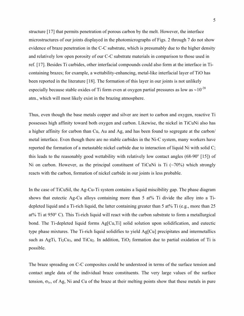
structure [17] that permits penetration of porous carbon by the melt. However, the interface
microstructures of our joints displayed in the photomicrographs of Figs. 2 through 7 do not show
evidence of braze penetration in the C-C substrate, which is presumably due to the higher density
and relatively low open porosity of our C-C substrate materials in comparison to those used in
ref. [17]. Besides Ti carbides, other interfacial compounds could also form at the interface in Ti-
containing brazes; for example, a wettability-enhancing, metal-like interfacial layer of TiO has
been reported in the literature [18]. The formation of this layer in our joints is not unlikely
especially because stable oxides of Ti form even at oxygen partial pressures as low as ∼10-28
atm., which will most likely exist in the brazing atmosphere.
Thus, even though the base metals copper and silver are inert to carbon and oxygen, reactive Ti
possesses high affinity toward both oxygen and carbon. Likewise, the nickel in TiCuNi also has
a higher affinity for carbon than Cu, Au and Ag, and has been found to segregate at the carbon/
metal interface. Even though there are no stable carbides in the Ni-C system, many workers have
reported the formation of a metastable nickel carbide due to interaction of liquid Ni with solid C;
this leads to the reasonably good wettability with relatively low contact angles (68-90° [15]) of
Ni on carbon. However, as the principal constituent of TiCuNi is Ti (~70%) which strongly
reacts with the carbon, formation of nickel carbide in our joints is less probable.
In the case of TiCuSil, the Ag-Cu-Ti system contains a liquid miscibility gap. The phase diagram
shows that eutectic Ag-Cu alloys containing more than 5 at% Ti divide the alloy into a Ti-
depleted liquid and a Ti-rich liquid, the latter containing greater than 5 at% Ti (e.g., more than 25
at% Ti at 950° C). This Ti-rich liquid will react with the carbon substrate to form a metallurgical
bond. The Ti-depleted liquid forms Ag[Cu,Ti] solid solution upon solidification, and eutectic
type phase mixtures. The Ti-rich liquid solidifies to yield Ag[Cu] precipitates and intermetallics
such as AgTi, Ti2Cu3, and TiCu2. In addition, TiO2 formation due to partial oxidation of Ti is
possible.
The braze spreading on C-C composites could be understood in terms of the surface tension and
contact angle data of the individual braze constituents. The very large values of the surface
tension, σlv, of Ag, Ni and Cu of the braze at their melting points show that these metals in pure
6
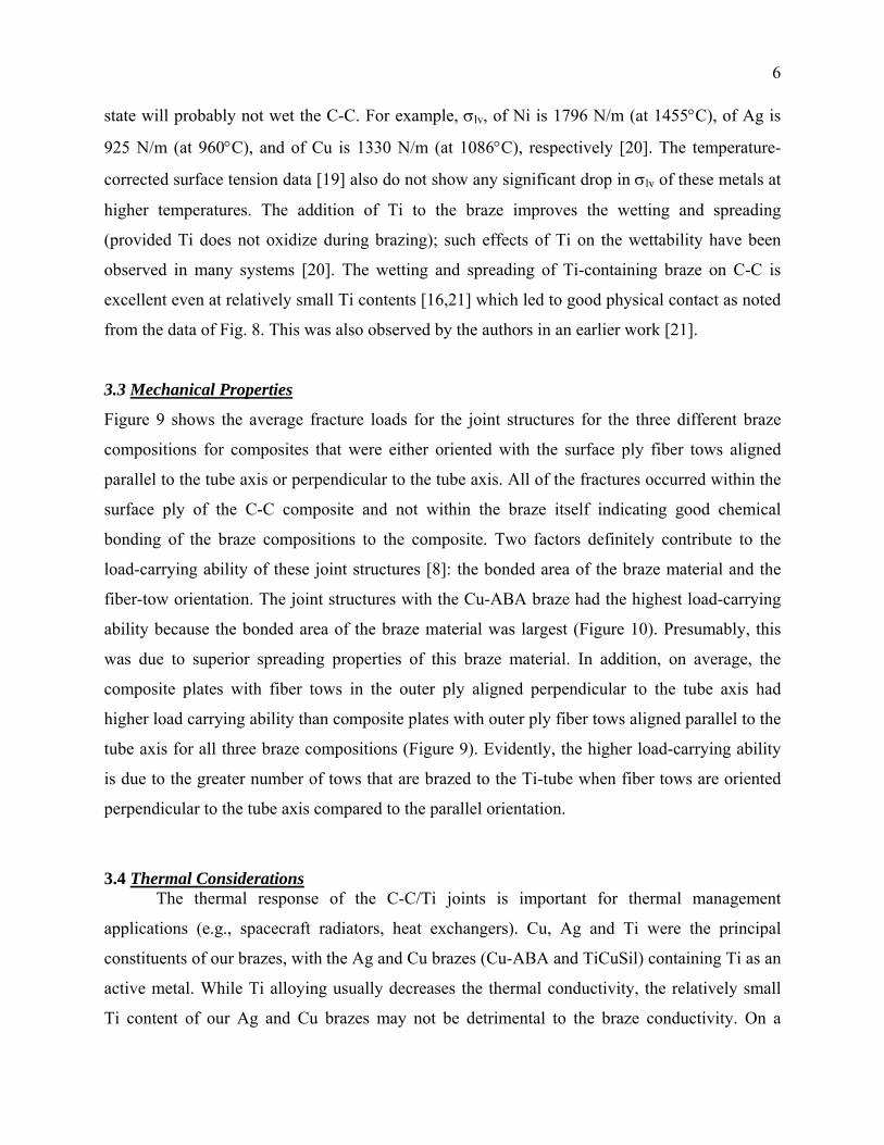
state will probably not wet the C-C. For example, σlv, of Ni is 1796 N/m (at 1455°C), of Ag is
925 N/m (at 960°C), and of Cu is 1330 N/m (at 1086°C), respectively [20]. The temperature-
corrected surface tension data [19] also do not show any significant drop in σlv of these metals at
higher temperatures. The addition of Ti to the braze improves the wetting and spreading
(provided Ti does not oxidize during brazing); such effects of Ti on the wettability have been
observed in many systems [20]. The wetting and spreading of Ti-containing braze on C-C is
excellent even at relatively small Ti contents [16,21] which led to good physical contact as noted
from the data of Fig. 8. This was also observed by the authors in an earlier work [21].
3.3 Mechanical Properties
Figure 9 shows the average fracture loads for the joint structures for the three different braze
compositions for composites that were either oriented with the surface ply fiber tows aligned
parallel to the tube axis or perpendicular to the tube axis. All of the fractures occurred within the
surface ply of the C-C composite and not within the braze itself indicating good chemical
bonding of the braze compositions to the composite. Two factors definitely contribute to the
load-carrying ability of these joint structures [8]: the bonded area of the braze material and the
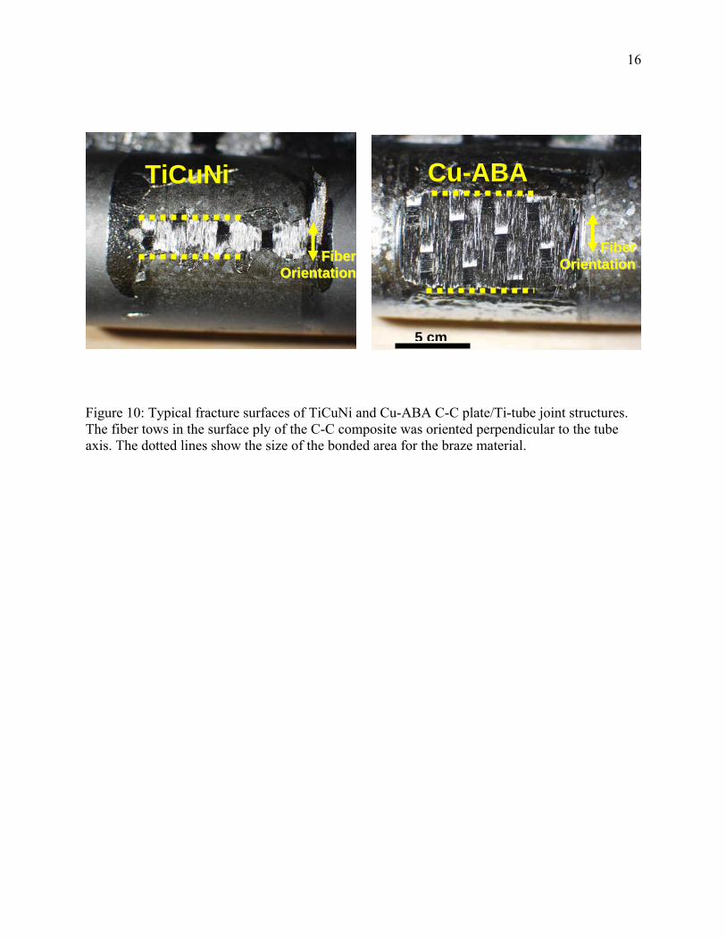
fiber-tow orientation. The joint structures with the Cu-ABA braze had the highest load-carrying
ability because the bonded area of the braze material was largest (Figure 10). Presumably, this
was due to superior spreading properties of this braze material. In addition, on average, the
composite plates with fiber tows in the outer ply aligned perpendicular to the tube axis had
higher load carrying ability than composite plates with outer ply fiber tows aligned parallel to the
tube axis for all three braze compositions (Figure 9). Evidently, the higher load-carrying ability
is due to the greater number of tows that are brazed to the Ti-tube when fiber tows are oriented
perpendicular to the tube axis compared to the parallel orientation.
3.4 Thermal Considerations
The thermal response of the C-C/Ti joints is important for thermal management
applications (e.g., spacecraft radiators, heat exchangers). Cu, Ag and Ti were the principal
constituents of our brazes, with the Ag and Cu brazes (Cu-ABA and TiCuSil) containing Ti as an
active metal. While Ti alloying usually decreases the thermal conductivity, the relatively small
Ti content of our Ag and Cu brazes may not be detrimental to the braze conductivity. On a
7
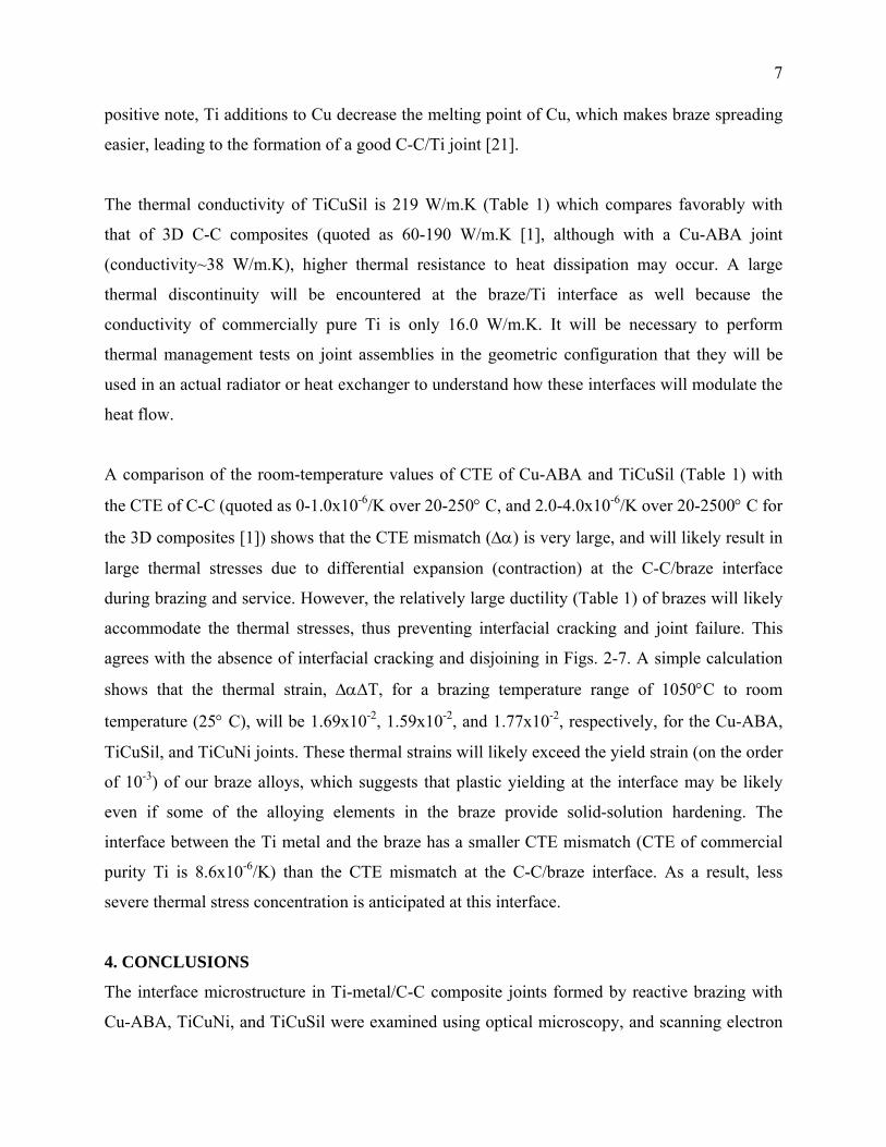
positive note, Ti additions to Cu decrease the melting point of Cu, which makes braze spreading
easier, leading to the formation of a good C-C/Ti joint [21].
The thermal conductivity of TiCuSil is 219 W/m.K (Table 1) which compares favorably with
that of 3D C-C composites (quoted as 60-190 W/m.K [1], although with a Cu-ABA joint
(conductivity~38 W/m.K), higher thermal resistance to heat dissipation may occur. A large
thermal discontinuity will be encountered at the braze/Ti interface as well because the
conductivity of commercially pure Ti is only 16.0 W/m.K. It will be necessary to perform
thermal management tests on joint assemblies in the geometric configuration that they will be
used in an actual radiator or heat exchanger to understand how these interfaces will modulate the
heat flow.
A comparison of the room-temperature values of CTE of Cu-ABA and TiCuSil (Table 1) with
the CTE of C-C (quoted as 0-1.0x10⁻⁶/K over 20-250° C, and 2.0-4.0x10⁻⁶/K over 20-2500° C for
the 3D composites [1]) shows that the CTE mismatch (∆α) is very large, and will likely result in
large thermal stresses due to differential expansion (contraction) at the C-C/braze interface
during brazing and service. However, the relatively large ductility (Table 1) of brazes will likely
accommodate the thermal stresses, thus preventing interfacial cracking and joint failure. This
agrees with the absence of interfacial cracking and disjoining in Figs. 2-7. A simple calculation
shows that the thermal strain, ∆α∆T, for a brazing temperature range of 1050°C to room
temperature (25° C), will be 1.69x10⁻², 1.59x10⁻², and 1.77x10⁻², respectively, for the Cu-ABA,
TiCuSil, and TiCuNi joints. These thermal strains will likely exceed the yield strain (on the order
of 10-3) of our braze alloys, which suggests that plastic yielding at the interface may be likely
even if some of the alloying elements in the braze provide solid-solution hardening. The
interface between the Ti metal and the braze has a smaller CTE mismatch (CTE of commercial
purity Ti is 8.6x10⁻⁶/K) than the CTE mismatch at the C-C/braze interface. As a result, less
severe thermal stress concentration is anticipated at this interface.
4. CONCLUSIONS
The interface microstructure in Ti-metal/C-C composite joints formed by reactive brazing with
Cu-ABA, TiCuNi, and TiCuSil were examined using optical microscopy, and scanning electron
8
microscopy (SEM) coupled with energy dispersive spectrometry (EDS). Evidence of solute
redistribution across the joint during brazing, and possible metallurgical bond formation via
interdiffusion led to good wetting and bonding. The mechanical characterization of the joints
using a Ti-tube/C-C plate joint tensile test indicated that both the area of bonding and the
orientation of the C fiber tows in the outer ply of the harness satin weave at the mating surface
affected the joint strength. The Cu-ABA braze material had the best spreading (bonded area) for
the Ti-Tube/C-C joint structures which enabled the highest joint strengths. Also, joint structures
with outer fiber tows oriented perpendicular to the tube axis had greater load-carrying ability
than joint structures with outer fiber tows oriented parallel to the tube axis for all three braze
compositions.
ACKNOWLEDGEMENT
The authors would like to thank Mr. Mike Halbig and Mr. J. Douglas Kiser for helpful
comments on the manuscript. R. Asthana acknowledges the award of a NASA/ASEE Faculty
Fellowship for research at NASA Glenn Research Center during June-Aug 2004.
REFERENCES 1. R. Taylor, “Carbon-matrix composites”; in Comprehensive Composite Materials, 4 pp. 387-426, Elsevier Science Ltd., Boston, 2000.
2. D. Lewis III and M. Singh, in ASM Handbook, 21 (2001) 668-673 ASM Int., Mater. Park, OH.
3. D. Goodman and R. Singler, NASA CR 97, 206679 (1998).
4. M.G. Nicholas, Joining of Ceramics, (1990) 73-93, Chapman & Hall, London.
5. P.G. Valentine and P.W. Trester in Proc., 15th Conference on Metal-Matrix, Carbon, and Ceramic-Matrix Composites, NASA CP-3133, Part I, J.D. Buckley (ed.) (1990) 39-55.
6. “Joining of carbon-carbon and ceramic-matrix composites”, Materials Innovations Lab Presentation, Inter-agency Planning Group Meet, S. Yalof (ed.); IDA Memo Report M-312, T.F. Kearns (ed.) (April 1987).
7. P. Dadras, Proceedings of the 14th Conf. Metal-, Carbon- and Ceramic-Matrix Compos., NASA CP 3097, Part 2, J.D. Buckley (ed.) (1990).
8. G.N. Morscher, R. Asthana, M. Singh, and T. Shpargel, "A Simple Test to Determine the Effectiveness of Different Braze Compositions for Joining Ti-Tubes to C/C Plates" (to be submitted). 9. R. Standing and M. Nicholas, J. Mater. Sci., 13 (1978) 1509-1514.
10. E.K. Storms, Refractory Carbides, Academic Press, New York, 1967.
9
11. J.G. Li, J. Mater. Sci. Lett., 11 (1992) 1551-1554.
12. N. Grigorenko, V. Poluyanskaya, N. Eustathopoulos, and Y. Naidich, in Interfacial Sci. of Ceram. Joining, Bellosi et al (eds.), Kluwer Acad. Publ., Boston (1998), 69-78.
13. O. Dezellus, F. Hodaj and N. Eustathopoulos, in Trans. JWRI, Osaka Univ. (Japan), N. Eustathopoulos, K. Nogi and N. Sobczak (eds.), 30 (2001) 75-84.
14. J. T. Whalen and A.T. Anderson, J. Amer. Ceram. Soc., 34[4] (1976) 378-383.
15. M. Humenik, Jr. and W.D. Kingery, J. Amer. Ceram. Soc., 37[1] (1954) 18-23.
16. N. Grigorenko, V. Poluyanskaya, N. Eustathopoulos, and Y. V. Naidich, in Proc. 2nd Int. Conf. on High-Temp. Capillarity, N. Eustathopoulos and N. Sobczak (eds.), Foundry Res. Inst. (Krakow) (1997) 27-35.
17. N. Sobczak, J. Sobczak, M. Ksiazek, W. Radziwill and J. Morgiel, in Proc. 2nd Int. Conf. on High-Temp. Capillarity, Eustathopoulos and Sobczak (eds.), Foundry Research Institute (Krakow) (1997) 97-98.
18. V.M. Pervertailo, O.B. Loginova, and N.G. Bagno, 143-147 in Trans. JWRI, Osaka Univ. (Japan), N. Eustathopoulos, K. Nogi and N. Sobczak (eds.), 30 (2001) 143-147.
19. B.J. Keene, Int. Mater. Revs., 38(4) (1993) 157-192.
20. Y.V. Naidich, in Progress in Surface and Membrane Science, Cadenhead and Danielli (eds.), Academic Press, New York (1981).
21. M. Singh, T.P. Shpargel, G. Morscher and R. Asthana, in Proc. of the 5th International Conference on High-Temperature Ceramic-Matrix Composites (HTCMC-5), M. Singh, R.J. Kerans, E. Lara-Curzio, and R. Naslain (eds.), The Amer. Ceramic Soc., Westerville, OH (2005) 457-462.
10
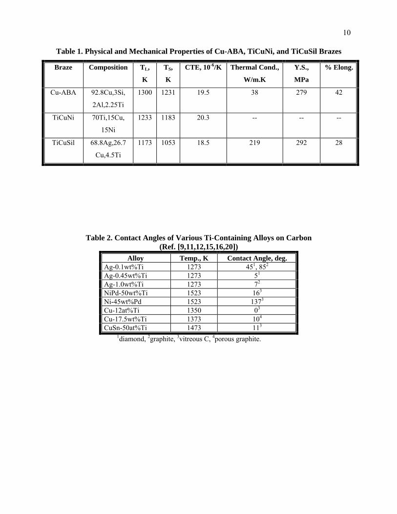
Table 1. Physical and Mechanical Properties of Cu-ABA, TiCuNi, and TiCuSil Brazes
Braze Composition TL,
K
TS,
K
CTE, 10-6/K Thermal Cond.,
W/m.K
Y.S.,
MPa
% Elong.
Cu-ABA 92.8Cu,3Si,
2Al,2.25Ti
1300 1231 19.5 38 279 42
TiCuNi 70Ti,15Cu,
15Ni
1233 1183 20.3 -- -- --
TiCuSil 68.8Ag,26.7
Cu,4.5Ti
1173 1053 18.5 219 292 28
Table 2. Contact Angles of Various Ti-Containing Alloys on Carbon (Ref. [9,11,12,15,16,20])
Alloy Temp., K Contact Angle, deg. Ag-0.1wt%Ti 1273 451, 852
Ag-0.45wt%Ti 1273 51
Ag-1.0wt%Ti 1273 72
NiPd-50wt%Ti 1523 163
Ni-45wt%Pd 1523 1373
Cu-12at%Ti 1350 03
Cu-17.5wt%Ti 1373 104
CuSn-50at%Ti 1473 113
1diamond, 2graphite, 3vitreous C, 4porous graphite.
11
Figure 1: Schematic of tube tensile test.
12
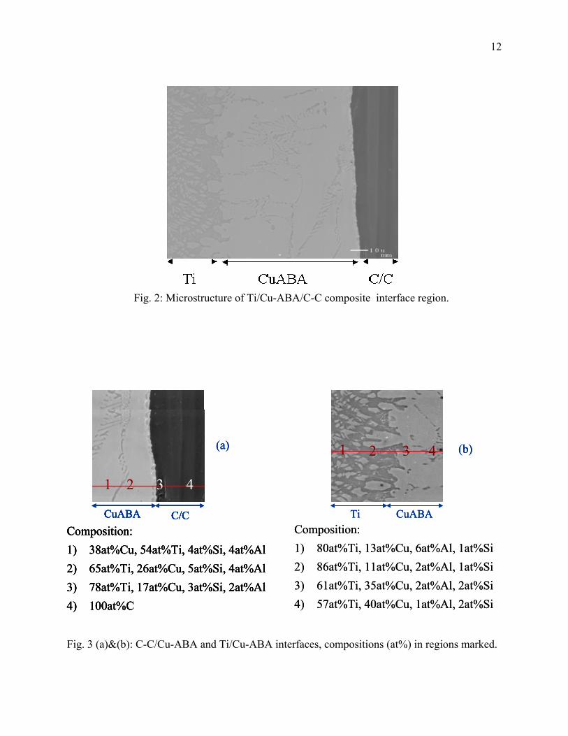
Fig. 2: Microstructure of Ti/Cu-ABA/C-C composite interface region.
C- C
1 2 3 4 1 2 3 4 1 2 3 4 1 2 3 4 1 2 3 4 4 3 1 2
1 2 3 4 (b)1 2 3 4 (b)1 2 3 4 2 3 4 (b)1
(a)(a)(a)
CuABA C/CCuABA C/CCuABA C/CCuABA C/CC/CCuABA Ti CuABA Ti CuABA CuABA Ti
Composition:Composition: Composition:Composition:Composition:Composition:
1)1) 80at%Ti, 13at%Cu, 6at%Al, 1at%Si80at%Ti, 13at%Cu, 6at%Al, 1at%Si 1)1)1)1) 38at%Cu, 54at%Ti, 4at%Si, 4at%Al38at%Cu, 54at%Ti, 4at%Si, 4at%Al38at%Cu, 54at%Ti, 4at%Si, 4at%Al38at%Cu, 54at%Ti, 4at%Si, 4at%Al2)2) 86at%Ti, 11at%Cu, 2at%Al, 1at%Si86at%Ti, 11at%Cu, 2at%Al, 1at%Si
2)2)2)2) 65at%Ti, 26at%Cu, 5at%Si, 4at%Al65at%Ti, 26at%Cu, 5at%Si, 4at%Al65at%Ti, 26at%Cu, 5at%Si, 4at%Al65at%Ti, 26at%Cu, 5at%Si, 4at%Al
3)3) 61at%Ti, 35at%Cu, 2at%Al, 2at%Si61at%Ti, 35at%Cu, 2at%Al, 2at%Si 3)3)3)3) 78at%Ti, 17at%Cu, 3at%Si, 2at%Al78at%Ti, 17at%Cu, 3at%Si, 2at%Al78at%Ti, 17at%Cu, 3at%Si, 2at%Al78at%Ti, 17at%Cu, 3at%Si, 2at%Al4)4) 57at%Ti, 40at%Cu, 1at%Al, 2at%Si57at%Ti, 40at%Cu, 1at%Al, 2at%Si
4)4)4)4) 100at%C100at%C100at%C100at%C
Fig. 3 (a)&(b): C-C/Cu-ABA and Ti/Cu-ABA interfaces, compositions (at%) in regions marked.
13
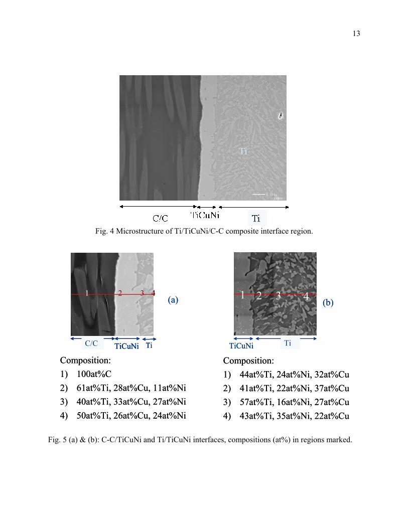
Fig. 4 Microstructure of Ti/TiCuNi/C-C composite interface region.
Fig. 5 (a) & (b): C-C/TiCuNi and Ti/TiCuNi interfaces, compositions (at%) in regions marked.
C-C
C-C
Composition:1) 44at%Ti, 24at%Ni, 32at%Cu2) 41at%Ti, 22at%Ni, 37at%Cu3) 57at%Ti, 16at%Ni, 27at%Cu4) 43at%Ti, 35at%Ni, 22at%Cu
Composition:1) 100at%C
2) 61at%Ti, 28at%Cu, 11at%Ni3) 40at%Ti, 33at%Cu, 27at%Ni4) 50at%Ti, 26at%Cu, 24at%Ni
1 2 3 4 1 2 3 4
C/C TiCuNi Ti TiCuNi Ti
(a) (b)
Composition:1) 44at%Ti, 24at%Ni, 32at%Cu2) 41at%Ti, 22at%Ni, 37at%Cu3) 57at%Ti, 16at%Ni, 27at%Cu4) 43at%Ti, 35at%Ni, 22at%Cu
Composition:1) 100at%C
2) 61at%Ti, 28at%Cu, 11at%Ni3) 40at%Ti, 33at%Cu, 27at%Ni4) 50at%Ti, 26at%Cu, 24at%Ni
1 2 3 4 11 2 3 4 2 3 4 1
C/C TiCuNi Ti
2 3 4 1 2 3 4 (a) (b)
C/C TiTi TiCuNiTiCuNi
14
Ti TiCuSil C/CTi TiCuSil C/C
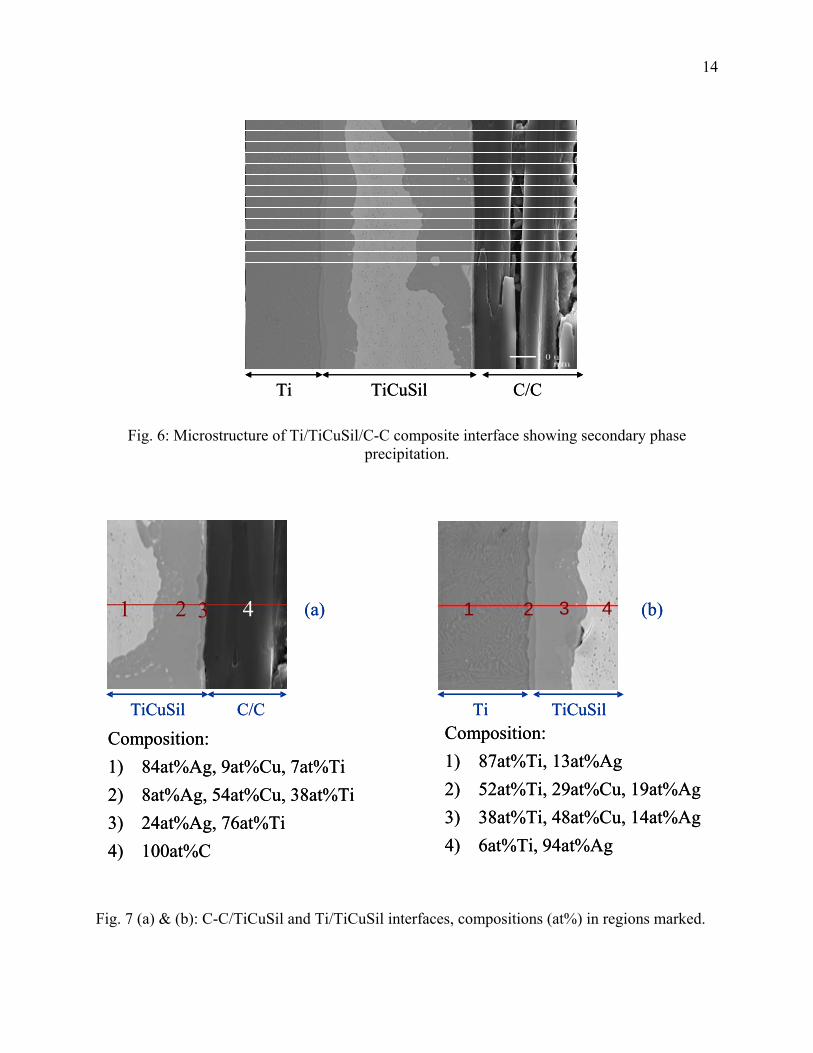
Fig. 6: Microstructure of Ti/TiCuSil/C-C composite interface showing secondary phase precipitation.
F
i
1 2 3 4 1 2 3 4 (a) (b)1 2 3 4 1 2 3 4 1 2 3 4 1 2 3 4 (a) (b)
T
ig. 7 (a) & (b): C-C/TiCuSil and Ti/TiCuSil interfaces, compositions (at%) in regions marked.
Composition:1) 84at%Ag, 9at%Cu, 7at%Ti2) 8at%Ag, 54at%Cu, 38at%Ti3) 24at%Ag, 76at%Ti 4) 100at%C
Composition:1) 87at%Ti, 13at%Ag
2) 52at%Ti, 29at%Cu, 19at%Ag3) 38at%Ti, 48at%Cu, 14at%Ag4) 6at%Ti, 94at%Ag
TiCuSil C/C Ti TiCuSil
Composition:1) 84at%Ag, 9at%Cu, 7at%Ti2) 8at%Ag, 54at%Cu, 38at%Ti3) 24at%Ag, 76at%Ti 4) 100at%C
Composition:1) 87at%Ti, 13at%Ag
2) 52at%Ti, 29at%Cu, 19at%Ag3) 38at%Ti, 48at%Cu, 14at%Ag4) 6at%Ti, 94at%Ag
TiCuSil C/C Ti TiCuSil

15
020406080
100120140160180
0 5 10 15 20 25% Ti
Con
tact
Ang
le, d
eg. Sn-Ti/graphite
Cu-Ti/graphite Ag-Ti/carbon Cu-Ti/v itreous C CuSn-Ti/v itreous C
Fig. 8: Effect of Ti on the contact angle of carbon with some metals. Data are from studies cited
in ref. [9,11,12,15,20].
0
5
10
15
20
25
TiC
uNi
(per
pend
icul
ar)
TiC
uNi
(par
alle
l)
TiC
uSil
(per
pend
icul
ar)
TiC
uSil
(p
aral
lel)
CuA
BA
(per
pend
icul
ar)
CuA
BA
(p
aral
lel)
Load
, N
7 8 9 8 5
+/-2.8N
+/-1.9N
+/-3.4N
+/- 12N
+/- 3.3N
+/-0.9N
6
+/- std dev.
1/2 inch wide C/C
Figure 9: Tensile failure loads of C-C plate, Ti-tube joints.
16
Cu-ABA TiCuNi
Figure 10: Typical fracture surfaces of TiCuNi and Cu-ABA C-C plate/Ti-tube joint structures. The fiber tows in the surface ply of the C-C composite was oriented perpendicular to the tube axis. The dotted lines show the size of the bonded area for the braze material.
FFiibbeerr OOrriieennttaattiioonn FFiibbeerr
OOrriieennttaattiioonn
5 cm