actively lubricated hybrid journal bearings based on
TRANSCRIPT

HAL Id: hal-02426104https://hal.archives-ouvertes.fr/hal-02426104
Submitted on 1 Jan 2020
HAL is a multi-disciplinary open accessarchive for the deposit and dissemination of sci-entific research documents, whether they are pub-lished or not. The documents may come fromteaching and research institutions in France orabroad, or from public or private research centers.
L’archive ouverte pluridisciplinaire HAL, estdestinée au dépôt et à la diffusion de documentsscientifiques de niveau recherche, publiés ou non,émanant des établissements d’enseignement et derecherche français ou étrangers, des laboratoirespublics ou privés.
Actively lubricated hybrid journal bearings based onmagnetic fluids for high-precision spindles of machine
toolsLuis Lopez de Lacalle, Harkaitz Urreta, Gorka Aguirre, Pavel Kuzhir, Luis
Norberto López de Lacalle
To cite this version:Luis Lopez de Lacalle, Harkaitz Urreta, Gorka Aguirre, Pavel Kuzhir, Luis Norberto López de Lacalle.Actively lubricated hybrid journal bearings based on magnetic fluids for high-precision spindles ofmachine tools. Journal of Intelligent Material Systems and Structures, SAGE Publications, 2019, 30(15), pp.2257-2271. 10.1177/1045389X19862358. hal-02426104

For Peer Review
Actively lubricated hybrid journal
bearings based on magnetic fluids for
high precision spindles of machine tools
Harkaitz Urreta1*, Gorka Aguirre
1, Pavel Kuzhir
2, Luis Norberto
Lopez de Lacalle3
1 IK4-IDEKO, Arriaga 2, E-20870 Elgoibar, Spain
2 University Côte d’Azur, CNRS UMR 7010 Inst. of Physics of Nice, Parc Valrose
06100 Nice, France
3 EHU-UPV Dept. Mechanical Engineering, Alameda Urquijo S/N, E-48013 Bilbao,
Spain
* Corresponding author [email protected]; Tel: +34943748000 ; Fax: +34943743804
Abstract
The research work reported in this paper is focused on the use of magnetic fluids as
active lubricant for improving the performance of hybrid journal bearings, with
application to high precision machine tools. Prototype design was optimized following
numerical computation of Reynolds equation and computational fluid dynamics (CFD)
calculations, in both cases with Herschel-Buckley model for the magnetorheological
fluid. This fluid (LORD Corp. MRF 122-2ED) was experimentally characterized in
detail. The improvement of the hydrodynamic effect in journal bearings was
demonstrated with 50% higher load capacity and stiffness, mainly at half of shaft
eccentricity 0.4<ε<0.7. Active hydrostatic lubrication achieved quasi-infinite stiffness
Page 1 of 53
http://mc.manuscriptcentral.com/jimss
Journal of Intelligent Material Systems and Structures
123456789101112131415161718192021222324252627282930313233343536373839404142434445464748495051525354555657585960

For Peer Review
within working limits (load and speed), at low frequencies. For high dynamic response
the active lubrication based on magnetorheological valves did not show good response.
The feasibility of using magnetic fluids for developing high performance machine tool
spindles and the validity of the simulation models was demonstrated experimentally.
Keywords
Magnetorheological fluid, MR valves, active bearing, CFD, machine tool, spindle.
Page 2 of 53
http://mc.manuscriptcentral.com/jimss
Journal of Intelligent Material Systems and Structures
123456789101112131415161718192021222324252627282930313233343536373839404142434445464748495051525354555657585960

For Peer Review
Nomenclature and main variables
b Recess width [m] S Stiffness [N/m]
B Magnetic flux density [T] t Time [s]
C Radial clearance [m] T Temperature [ºC]
F Force [N] W Load capacity [N]
Ff Friction force [N] x,y,z Linear coordinates [-]
h Film thickness [m] r,θ,z Cylind. coordinates [-]
H Magnetic field strength [A/m] u,v,w Fluid velocity [m/s]
l Recess length [m] Shear rate [1/s]
L Bearing length [m] θ Angular coordinate [º]
n Number of pockets [-] ρ Density [kg/m3]
p Pressure distribution [Pa] σ Stress [Pa]
Pr Recess pressure [Pa] τ Shear stress [Pa]
Pp Pumping pressure [Pa] µ Dynamic viscosity [Pa·s]
Q Flowrate [m3/s] ν Kinematic viscosity [m
2/s]
R Radius [m] φ Attitude angle [º]
Ra Shaft radius [m] ψ Angular abscissa [º]
Rc Bearing raius [m] Ω Angular speed [1/s]
Rh Hydraulic resistance [Pa·s/m3]
Ro Hydraulic resist. bearing [Pa·s/m3]
Ri Hydraulic resist. restrictor [Pa·s/m3]
= 11 +
Hydraulic resistance ratio
R
L
2=λ
Length to
diameter ratio
R
e=ε
Relative eccentricity
ωµτ
τR
C
0
0*
0 =
Dimensionless
yield stress
R
xX
∆=∆
Dimensionless element
size in tangential
direction C
hH =
Dimensionless
gap size
h
hY
∆=∆
Dimensionless element
size in radial direction ( )µω
2RCp
P = Dimensionless
pressure
L
zZ
∆=∆
Dimensionless element
size in axial direction ( )
µω
2RC
dx
dp
Xd
Pd=
Dimensionless
pressure gradient
tangential
R
vu x
ω=
Dimensionless velocity
in tangential direction ( )
µω
2RC
dz
dp
Zd
Pd=
Dimensionless
pressure gradient
axial
R
vw z
ω=
Dimensionless velocity
in axial direction
Page 3 of 53
http://mc.manuscriptcentral.com/jimss
Journal of Intelligent Material Systems and Structures
123456789101112131415161718192021222324252627282930313233343536373839404142434445464748495051525354555657585960

For Peer Review
INTRODUCTION
The introduction to this research work has three sections, 1) a brief introduction to
classic lubricated bearings with hydrostatic and hydrodynamic lubrication, 2) active
bearings and 3) active hybrid journal bearings with magnetic fluid.
Hydrostatic and hydrodynamic lubrication bearings
Pressurized lubricated bearings, commonly known as hydrostatic or hydrodynamic
bearings, are quite widely used and known by manufacturers of high-precision machine
tools. Most influencing authors in the machine tool building field, for instance M. Weck
(Weck, 1984), agree that between the available technologies for guiding systems, namely
sliding, rolling and pressurized lubricant technologies, the latter offers better properties,
considering resolution, damping and smoothness in the movement. Lubricated bearings
can work in either hydrostatic or hydrodynamic regime, in function of the boundary
conditions, i.e.: external oil pressurization, geometry of the bearing, fluid viscosity and
applied load.
Hydrodynamic bearings, where pressure is generated by relative motion between the
bearing surfaces (Frêne et al., 1997), are suitable for applications where working
conditions are quite stationary. Thus, with a proper design of the bearing, a stable and
safe pressurized oil thin film can be achieved between the moving parts, the shaft and the
bearing, avoiding any contact, friction and therefore wear. The pressure in the bearing
follows the classic equation in thin fluid films proposed by Osborne Reynolds (Reynolds,
1886). The main hydrodynamic bearing drawback are the starting and deceleration
stages, where fluid velocity is so low that lubricant film cannot support the load, leading
to contact, friction and wear of surfaces.
To avoid contact and wear whatever is relative movement speed, hydrostatic
lubrication (Bassani and Piccigallo, 1992) is the proper solution. In this case, lubricant
Page 4 of 53
http://mc.manuscriptcentral.com/jimss
Journal of Intelligent Material Systems and Structures
123456789101112131415161718192021222324252627282930313233343536373839404142434445464748495051525354555657585960

For Peer Review
fluid pressure is provided by an external hydraulic pump, which ensures a fully
developed thin lubricant film between bearing and shaft. The bearing behaviour is
strongly dependent on the selection of compensation valves, commonly known as
restrictors. Restrictors determine fundamental mechanical properties of the bearing, like
stiffness and force. With increasing shaft speed, hydrodynamic pressure appears in the
hydrostatic bearings, as described by Reynolds equation. Hydrostatic bearings can thus,
in function of the geometry, oil viscosity and operational conditions, become in a “hybrid
bearing” with mixed hydrodynamic and hydrostatic lubrication regime. Figure 1 scheme
shows the bearing hydrodynamic pressure governed by Reynolds equation (1).
[insert figure 1]
Figure 1 Hydrodynamic pressure in journal bearings.
Figure 2 shows the implementation of hydrostatic lubrication ruled by the basic
equations (2).
[insert figure 2]
Figure 2 Hybrid journal bearing and hydraulic circuit
The improvement of the performance of journal bearing with hybrid lubrication by
means of active magnetic fluids will be discussed in this paper.
Active bearings for smart systems
Following Reynolds and hydrostatic lubrication basic equations, see Eqs. (1) and (2),
an active lubricated bearing can be achieved by the modification of bearing geometry,
fluid viscosity and/or restrictor hydraulic resistance, the latter in the case of hydrostatic
bearings.
( ) ( ) hVUUx
hx
hUU
z
ph
zx
ph
xρρρρ
µρ
µρ
&121266 2121
33
++−∂∂
+∂
∂+=
∂
∂
∂∂
+
∂
∂
∂∂
(1)
= · =
· = ·
= ! (2)
Page 5 of 53
http://mc.manuscriptcentral.com/jimss
Journal of Intelligent Material Systems and Structures
123456789101112131415161718192021222324252627282930313233343536373839404142434445464748495051525354555657585960

For Peer Review
Geometry change is a very complex option due the requirement of a mechanism to
produce micrometric deformation with as large as possible stiffness. This solution has
been explored with active air bearings by including flexible structures driven by piezo
actuators (Aguirre et al., 2010; Morosi and Santos, 2011; Shamoto et al., 2006), but they
are not transposable to high pressure hybrid journal bearings. Working with oil lubricated
bearings, different approaches can be found in bibliography for pure hydrodynamic cases,
e.g. closed loop control in oil feeding (Albers et al., 2011) to improve the energy
efficiency of guiding, and in the particular case of tilting pads hydrodynamic bearings
(Deckler, 2004; Nicoletti and Santos, 2003; Sun and Krodkiewski, 1999), the lubrication
conditions and tilting angle of pads were modified by hydraulic or electromechanical
actuators.
Regarding active bearings with hydrostatic lubrication, therefore with active restrictors
(Jordan, 2000), some other research works aimed at a) the improvement of hybrid
bearings with servo-valves (Santos and Watanabe, 2006), b) the study of active
lubrication in complex multibody simulation (Estupiñan and Santos, 2009), and c) special
considerations required for flexible rotors typical of energy generation machinery
(Nicoletti and Santos, 2008). But a common characteristic in all those works was either
the use of complex mechanisms for the bearing, or precise servo-valves for lubricant
feeding.
Active hybrid lubricated bearings with magnetic fluids
A second research strand about actively lubricated bearings was focused on the use of
fluids with rheological response under external exciting fields: electro-rheological fluids
and magnetic fluids.
Electrorheological fluids change their rheology under electric field, increasing the
shear stress proportionally to the field. Some research works developed active bearings
(hydrodynamic and hydrostatic) using this kind of fluid as lubricant, e.g. in high-speed
journal bearings to control stiffness and stability (G. Nikolakopoulos and Papadopoulos,
1998), describing the theoretical behaviour of journal bearings lubricated with active
Page 6 of 53
http://mc.manuscriptcentral.com/jimss
Journal of Intelligent Material Systems and Structures
123456789101112131415161718192021222324252627282930313233343536373839404142434445464748495051525354555657585960
For Peer Review
fluids (Peng and Zhu, 2005), and studying the use of electrorheological fluids for active
hydrostatic bearings (Bouzidane et al., 2008). In all those cases the high voltage (in the
range of 1-10kV) electric field required achieve a high enough electrorheological effect
was reported as a serious drawback for industrial implementation.
Regarding magnetic fluids, two main groups can be noted: ferrofluids and
magnetorheological fluids, hereinafter MRF. All magnetic fluids are composed by a
carrier fluid (lubricant oil in this case), additives to improve tribology and fluid stability,
and magnetic particles, which in function of their size (nanometric or micrometric) define
their behaviour. Ferrofluids contain stabilized nanometric particles (5-12nm diameter),
where due to their size and energy balance (gravity < particle’s thermal energy) the
colloidal suspension is stable in time. Those particles are usually formed by iron or cobalt
oxides, covered with surfactants (oleic acid-like, the most extended) to avoid aggregation
and final settling of particles. The most relevant reference is the compilation book by S.
Odenbach (Odenbach, 2002), in which fluids synthesis, rheological characterization and
several applications are discussed.
The MRF are similar to ferrofluids but magnetic particles are in the range of
micrometres, from 1-10µm, mainly made of carbonyl iron powder, hereinafter CIP. They
are strongly unstable, as a matter of fact in few minutes the particles are settled on the
tank bottom. To avoid agglomeration and to have a quick restoration of homogeneous
MRF, the fluid may include several additives, and in a few removing or pumping cycles
the fluid can get its original behaviour.
The application of magnetic fluids in lubricated bearings was studied in some previous
works with two main approaches: Hydrodynamic and hydrostatic. In the case of
hydrodynamic bearings the magnetic field is applied directly into the bearing, modifying
the rheology of the fluid in the pressurized thin film. The hydrostatic lubrication is based
in the active restrictor that feed the bearing with controlled flowrate and pressures.
Starting with hydrodynamic lubrication, notorious changes in the Stribeck curve were
observed experimentally with the use of ferrofluids (Spur and Patzwald, 1998). The use
Page 7 of 53
http://mc.manuscriptcentral.com/jimss
Journal of Intelligent Material Systems and Structures
123456789101112131415161718192021222324252627282930313233343536373839404142434445464748495051525354555657585960

For Peer Review
of ferrofluids in lubricated bearings design was also tackled by Osman et al., (T. A.
Osman et al., 2001), focusing on the static and dynamic response (T.A. Osman et al.,
2001), and the misalignment effect between shaft and bearing (Osman, 2001). A deeper
approach about magnetic fluids as lubricants was developed by (Uhlmann et al., 2002)
with a later application to journal bearings (Uhlmann and Bayat, 2003). More recent
works in this matter (Kuzhir et al. 2011; Hsu et al. 2013), aimed at the study of the free
boundary laws and the effect of surface roughness.
In the case of hydrostatic lubrication, the flowrate and pressure in a basic test bench by
magnetic field under variable external loads was explored (Hesselbach and Abel-
Keilhack, 2003). The same authors studied posteriorly the vibrational response of the
bearings as active dampers (Díaz-Tena et al., 2013; Guldbakke and Hesselbach, 2006).
Valves (or restrictors) with magnetic fluids for hydrostatic bearings determine the
pressure drop in function of flowrate and applied magnetic field ((Songjing et al., 2002)).
Results from different MRF and characterization of fluids in valve mode was presented
in(Bin Mazlan, 2008)).
Considering that ferrofluids are highly stable but show very low magnetoviscous
effect as bearings lubricant ((Urreta et al., 2010)); and that MRF, unstable but with very
high magnetorheology response, the research presented in this paper was conducted
exclusively with MRF. Thus,
Section 2 describes the modelling and characterization of the magnetic fluid used in
the research; Section 3 deals with the mathematical modelling of the active hybrid journal
bearing; Section 4 presents the prototypes for experimental validation; Section 5
summarizes the results, and finally Section 6 the main conclusions.
CHARACTERIZATION OF
MAGNETORHEOLOGICAL FLUIDS
A commercial magnetorheological fluid from LORD® Corp. model MRF 122-2ED
was used in this research. First at all, experimental characterization of the fluid was
Page 8 of 53
http://mc.manuscriptcentral.com/jimss
Journal of Intelligent Material Systems and Structures
123456789101112131415161718192021222324252627282930313233343536373839404142434445464748495051525354555657585960

For Peer Review
carried out. Data given by manufacturers are usually approximate values, both for
magnetic and rheological behaviour. Therefore the fluid magnetic response was studied,
along with the rheological properties under applied magnetic field and temperature.
MRFs are strongly non-Newtonian fluids, presenting a strong yield stress in function
of applied magnetic field before fluid flows. The computational model to consider its
behaviour was Herschel-Buckley given by Eq. (3), which is the classical Bingham model
modified with thinning effect, as shown in Figure 3. Equation (4) is the apparent viscosity
of the non-Newtonian fluid, the viscosity that would have a Newtonian fluid with the
same shear stress (τ) at that strain rate ().
[insert figure 3]
Figure 3 Models for magnetic fluids characterization.
( )( ) ( )γγττ && sgn1
0
mKH +=
(3)
μ#$$ = τ γ (4)
The magnetic characterization was performed with a Magnet-Physik Permagraph L
magnetometer and the electromagnet EP-3, from which the magnetic field strength, flux
density and magnetic fluid permeability were obtained, as shown in Figure 4. The
magnetorheological characterization was carried out with a Thermo HAAKE RheoStress
RS150 control stress rheometer, with a magnetic module and a thermally controlled plate.
[insert figure 4]
Figure 4 Magnetic characterization of MRF 122–2ED from LORD Corp.
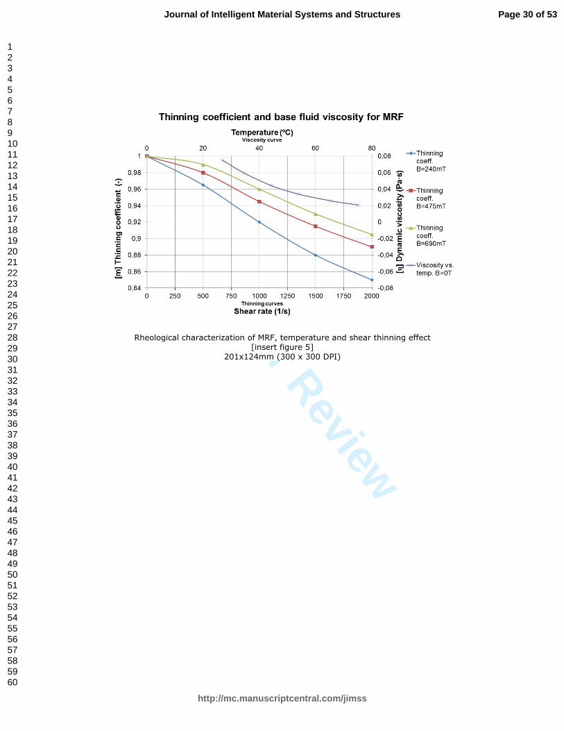
Rheological analysis of the MRF was carried out, and the results are presented in
Figure 5, i.e., temperature effect in viscosity and shear thinning effect in function of the
Page 9 of 53
http://mc.manuscriptcentral.com/jimss
Journal of Intelligent Material Systems and Structures
123456789101112131415161718192021222324252627282930313233343536373839404142434445464748495051525354555657585960
For Peer Review
magnetic field; in Figure 6, yield stress and base fluid viscosity in function of applied
magnetic field at room temperature.
[insert figure 5]
Figure 5 Rheological characterization of MRF, temperature and shear thinning effect.
[insert figure 6]
Figure 6 Rheological characterization of MRF, shear stress and base viscosity.
LUBRICATION MODEL WITH MAGNETIC FLUIDS
Mathematical modelling of MRF based lubrication was carried out in this section, in
order to improve the designing and optimize the behaviour of the prototypes. Modelling
is focused on determining i) pressure in the fluid, ii) velocity distribution (flowrate) and
iii) magnetic field in the bearing and valves. The design of the bearing and valve
prototypes is discussed in Section 4, together with the test benches for experimental
characterization.
Calculations and fluid simulations were carried out with two tools, in both cases
considering non-Newtonian fluid: a) for two-dimensional models, modified Reynolds
equation is solved into a MATLAB® based program, and b) for three-dimensional cases,
computational fluid dynamics (CFD) is used with SIEMENS NX® Advanced Flow.
Magnetic simulations were performed to determine the magnetic field strength and flux
density with the commercial software FLUX from CEDRAT®.
Page 10 of 53
http://mc.manuscriptcentral.com/jimss
Journal of Intelligent Material Systems and Structures
123456789101112131415161718192021222324252627282930313233343536373839404142434445464748495051525354555657585960
For Peer Review
Modelling was applied to two elements, described in the following two sub-sections:
1) Hybrid journal bearings and 2) magnetorheological (MR) valves.
Hybrid journal bearing lubricated with MRF
The solution of lubrication with magnetic fluids is based in a modified Reynolds
equation, where the behaviour of the fluid ranges from Newtonian to non-Newtonian
response. To solve the modified Reynolds equation, principles studied by (Dorier and
Tichy, 1992; Tichy, 1991) were assumed, modifying the Bingham equation for the
Herschel-Buckley model.
In the MRF lubrication, strong fluid yield stress requires a non-linear approach for
solving the model. In this case, the shear stress in the fluid is evaluated across the gap
radial section to determine the zone where the fluid is flowing and where it is plug. In
Figure 7 the zones I and II are flowing; and in the zone III there is plug fluid (or pseudo-
plastic MRF):
[insert figure 7]
Figure 7 Balance of forces on a fluid element in the plug region, MRF lubrication
Considering equations (1), (3), and (4), the Reynolds equation, Herschel-Buckley
model and apparent viscosity respectively, the equation to solve is:
3
26h
hhR
papp
∗−=
∂∂
ωρµθ
(5)
Considering the behaviour of MRF fluids, and the plug formation under magnetic
field, velocity distribution of the fluid is defined with next equations, see Figure 8:
I) ( ) ( )[ ]221
2
1yhh
xd
pd
Kyu aax −−
−=
( )ahy ≤≤0
(6)
II) ( ) ( ) ( )[ ]221
2
1bbx hyhh
xd
pd
Kyu −−−
−=
( )hyhb ≤≤
(7)
Page 11 of 53
http://mc.manuscriptcentral.com/jimss
Journal of Intelligent Material Systems and Structures
123456789101112131415161718192021222324252627282930313233343536373839404142434445464748495051525354555657585960

For Peer Review
III) ( ) 21
2
1ax h
xd
pd
Kyu
−=
( )ba hyh ≤≤
(8)
[insert figure 8]
Figure 8 Velocity distribution in a MRF under magnetic field with plug region (III)
Where the overall flow-rate in the bearing is:
( ) ( ) ( ) Ldyhyhudyhyhudyhyub
ab
a h
h
bax
h
h
bx
h
ax
<<+<<+<<= ∫∫∫
0
0Q
(9)
The modified Reynolds equation is solved numerically by finite difference method, in
which the bearing is discretized in “n” elements (i x j), and the equilibrium equation is
solved (10).
BPAPAPAPAPA jijijijiji ++++= −+−+ 1,41,3,12,11,0 (10)
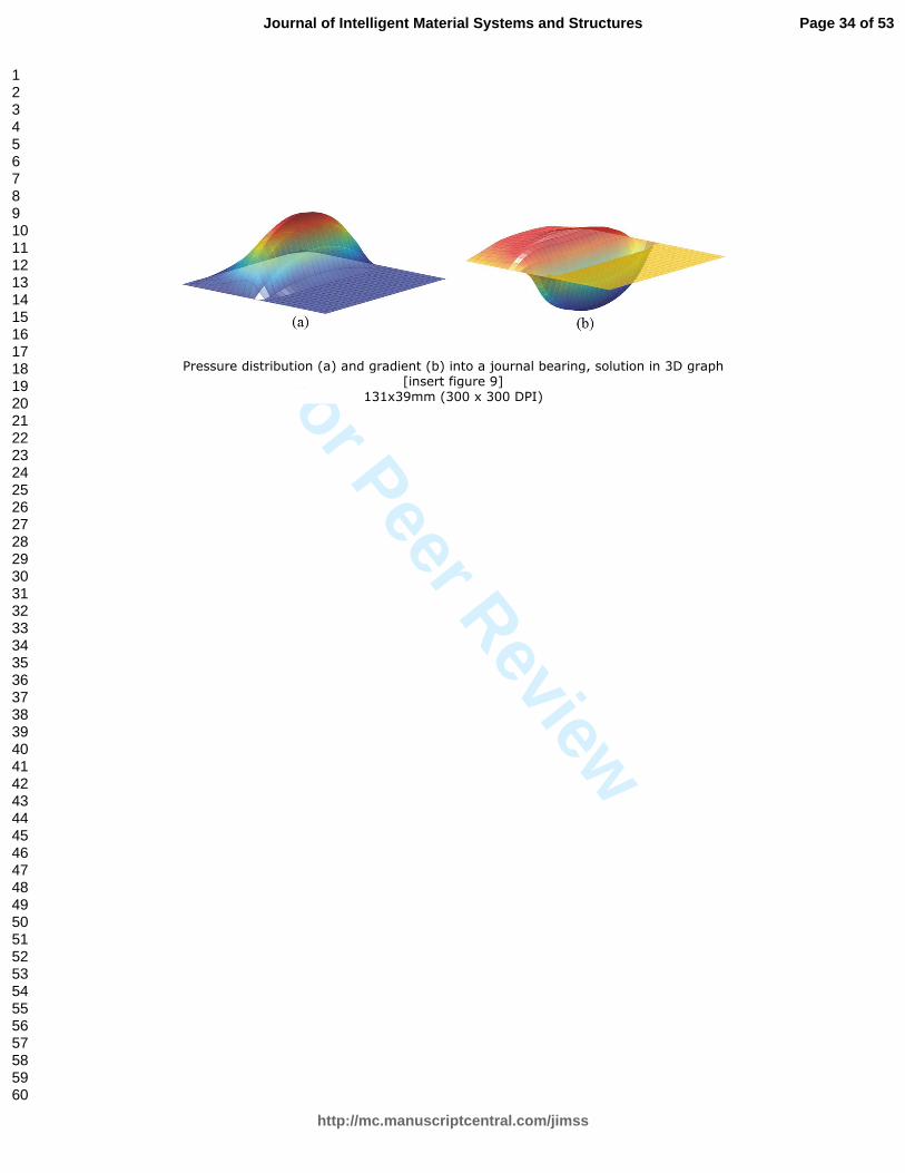
Solving this equation, the pressure profile (Figure 9), the velocity distribution of the
magnetic fluid in the bearing and therefore the load capacity, stiffness and flowrate were
obtained.
[insert figure 9]
Figure 9 Pressure distribution (a) and gradient (b) into a journal bearing, solution in
3D graph.
Reynolds-based modelling was used for two-dimensional cases, like plain journal
bearings. In the case of three dimensional models like hybrid bearings with recesses and
the MR valve, the CFD tool was implemented with Herschel-Buckley model for non-
Newtonian fluids, which is modified to be solved at any shear stress with a base viscosity
(11). It means that below a certain shear rate value, viscosity is Newtonian and given by
user ('(), and above that value, the viscosity is calculated for each element.
Page 12 of 53
http://mc.manuscriptcentral.com/jimss
Journal of Intelligent Material Systems and Structures
123456789101112131415161718192021222324252627282930313233343536373839404142434445464748495051525354555657585960

For Peer Review
' = '(0 ≤ ≤,'(
' = - + ,( >,'(
(11)
Active magnetorheological (MR) valves
Magnetorheological (MR) valve was calculated with CFD software, where the
pressure drop in the valve was determined for different flowrates and applied magnetic
fields. As shown in Figure 10, the valve has a coaxial architecture with two squeeze
surfaces where pressure drop and flowrate was controlled. Moreover, velocity and
flowrate of the fluid were calculated as shown in Figure 10b.
Magnetic calculations were carried out to determine the magnetization of the fluid.
Figure 11 shows the magnetic simulation of the MR valve, which was designed for the
hybrid journal bearing, with the magnetic flux density plotted for some critical points of
the valve.
[insert figure 10]
Figure 10 CFD simulations of MR valve, pressure drop (a) and flow-rate calculation
(b).
[insert figure 11]
Figure 11 Magnetic simulation of MR valve (a) and magnetic field in control points
(b).
Page 13 of 53
http://mc.manuscriptcentral.com/jimss
Journal of Intelligent Material Systems and Structures
123456789101112131415161718192021222324252627282930313233343536373839404142434445464748495051525354555657585960

For Peer Review
DESING OF PROTOTYPE AND TEST BENCH
Being the main aim of this research the development of magnetic fluid based
technology for machine-tool active spindles, two kind of devices were tested: a)
magnetorheological valves for active lubrication, and b) a hybrid journal bearing with
active compensation.
Magnetorheological (MR) valves
Four MR valves were dimensioned and designed to be used in the hybrid journal
bearing that will be described in the next section. Each of the four valves was composed
of two commercial electromagnets with coaxial architecture, in which the fluid flows
through two squeeze areas where the magnetic field is concentrated. Figure 12 shows the
valve and main design parameters
[insert figure 12]
Figure 12 MR valve for hybrid bearing, design sketches (a) and working principle
(b).
The gap for the fluid is 0.6mm, the external diameter (D_ext) is 30mm and the internal
diameter of squeeze area under magnetic field (D_int) is 24mm. Coils used in the valve
had 850 turns of 0.15mm diameter wires, for a maximum 5A current, so that, as shown in
Figure 11(a) the field induced in the fluid it is up to 800mT. In Figure 13 the valves and
parts are shown.
[insert figure 13]
Figure 13 MR valves picture with description of parts
Page 14 of 53
http://mc.manuscriptcentral.com/jimss
Journal of Intelligent Material Systems and Structures
123456789101112131415161718192021222324252627282930313233343536373839404142434445464748495051525354555657585960

For Peer Review
Hybrid journal bearing
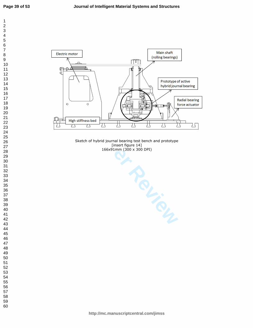
The hybrid journal bearing demonstrator was composed by two main parts: the main
structure with electric motor, main shaft and bed (the test bench), and the prototype of
bearing system with monitoring and magnetic systems, see Figure 14.
[insert figure 14]
Figure 14 Sketch of hybrid journal bearing test bench and prototype
The main shaft was guided by high precision rolling bearings with runout below 2µm,
and a semi-shaft was attached to be tested into the bearing, as shown in Figure 15. The
shaft was driven by an electric motor, with two transmission belts. The system was
clamped onto a heavy and stiff table to ensure stability. The bearing was made in bronze
to ensure good tribological properties and to guide properly the magnetic field generated
by two coils into the MRF. This system was mounted in the bearing house, which was
guided with two perpendicular linear rolling guides to ensure two degrees of freedom
between bearing and shaft, radial movement.
Load was applied radially on the bearing with a screw and a load cell (INTERFACE
SM 20kN), and the displacements derived by the load were measured with two eddy
current probes (Brüel&Kjaer SD-081) with a resolution below 1µm.
[insert figure 15]
Figure 15 Hybrid journal bearing test bench, overall view
[insert figure 16]
Figure 16 Hybrid journal bearing prototype, bearing house section view and
dimensions
Page 15 of 53
http://mc.manuscriptcentral.com/jimss
Journal of Intelligent Material Systems and Structures
123456789101112131415161718192021222324252627282930313233343536373839404142434445464748495051525354555657585960
For Peer Review
Figure 16 shows a detailed view of the bearing house and active bearing system, and
the main geometrical values of the hybrid bearing and recesses.
The four magnetorheological valves shown in previous section were located close to
the bearing house. Valves were working in closed-loop control with a real-time
controller, INGETEAM IC3. The control diagram is shown in Figure 17. Each valve had
its signal amplifiers providing up to 5A with 24V, while the fluid was pumped with a
hydraulic system composed by a pump/tank module and a pressure relief valve.
[insert figure 17]
Figure 17 Active hybrid journal bearings hydraulic circuit and control
RESULTS AND DISCUSSION
The results are split into two sections: magnetorheological (MR) valves and active
hybrid journal bearing.
Magnetorheological valves
Calculations were carried out with CFD due to the complexity of the flow into the
channels, and they were compared with experimental results from the prototype. The first
step was the calculation of magnetic field into the valve (see Figure 11), with flux density
isovalues (a) and some control points in function of the current through the coils. After
calculating the magnetic field values, the expected rheology of MRF was determined
based on the experimental results (see Figure 5 and Figure 6). The final step was the
computation in CFD of the flow rate and pressure drop in to the MR valve. To achieve
right results from simulations, the viscosity for low shear rate (µ0) was adjusted, a value
selected in the computation to solve Navier-Stokes equations including Herschel-Buckley
Page 16 of 53
http://mc.manuscriptcentral.com/jimss
Journal of Intelligent Material Systems and Structures
123456789101112131415161718192021222324252627282930313233343536373839404142434445464748495051525354555657585960

For Peer Review
model, equation (11). A good agreement was achieved with a constant ratio in all the
simulations of ,0/·'0 ≈ 200 (see Figure 18).
[insert figure 18]
Figure 18 Experimental and theoretical results in the MR valve for active bearing
Active hybrid bearing
The experimental analysis of the active hybrid journal bearing was carried out
regarding three aspects: load capacity, time response and wear during operation.
Load capacity and stiffness of the active hybrid journal bearing
Load capacity and stiffness in the active hybrid bearings were experimentally studied
in two ways: 1) the hydrodynamic effect improvement due to the magnetic fluid flow in
the bearing, and 2) the hydrostatic response with the four MR valves feeding the recesses
and working in closed loop control.
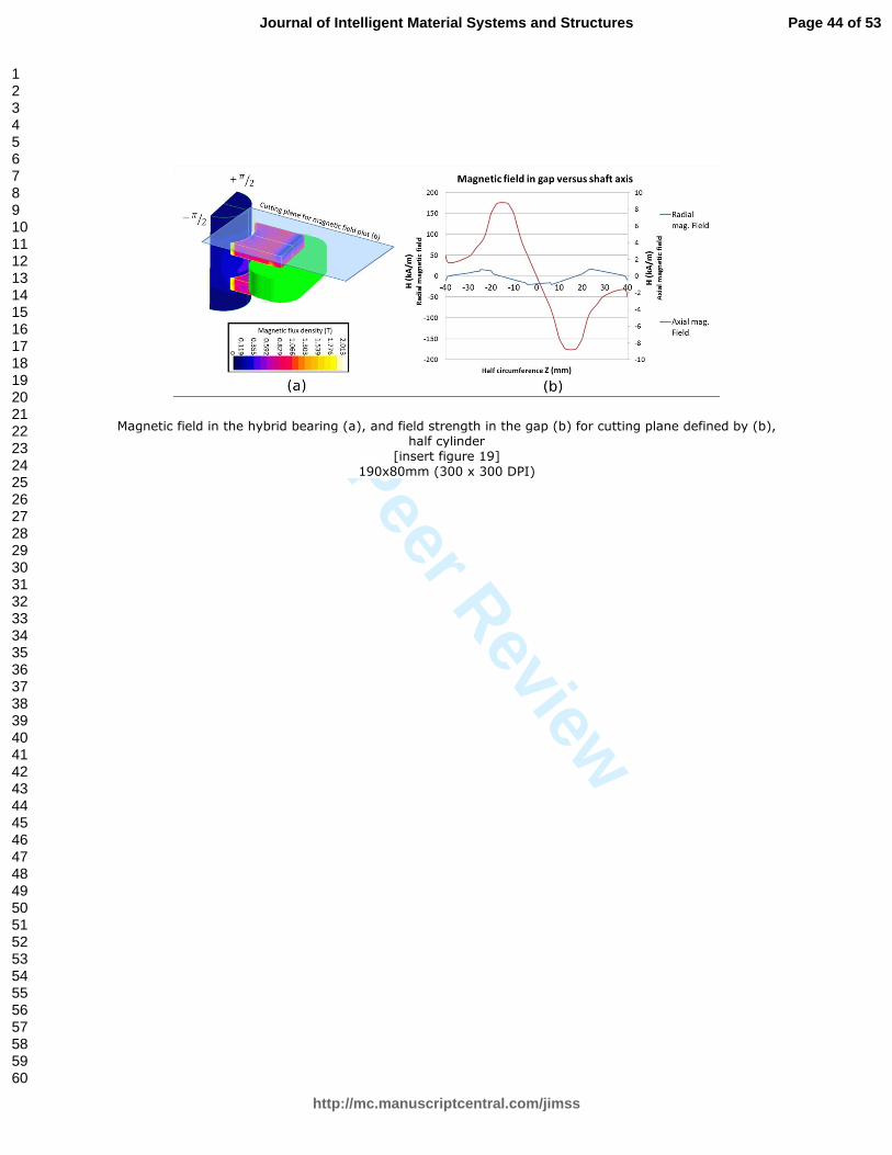
To determinate the hydrodynamic active response, the first step was to calculate the
magnetic field intensity in the clearance, where the results for a half model of the system
(symmetry assumption) are shown in Figure 19:
[insert figure 19]
Figure 19 Magnetic field in the hybrid bearing (a), and field strength in the gap (b)
for cutting plane defined by (b), half cylinder.
With those magnetic field values and the magnetic fluid model implemented in the
modified Reynolds equation (5), hydrodynamic response was evaluated for MRF, and
compared with experimental results, see Figure 20 and Figure 21. The tests were carried
out at two rotational speeds: 50 rpm and 200rpm.
Page 17 of 53
http://mc.manuscriptcentral.com/jimss
Journal of Intelligent Material Systems and Structures
123456789101112131415161718192021222324252627282930313233343536373839404142434445464748495051525354555657585960

For Peer Review
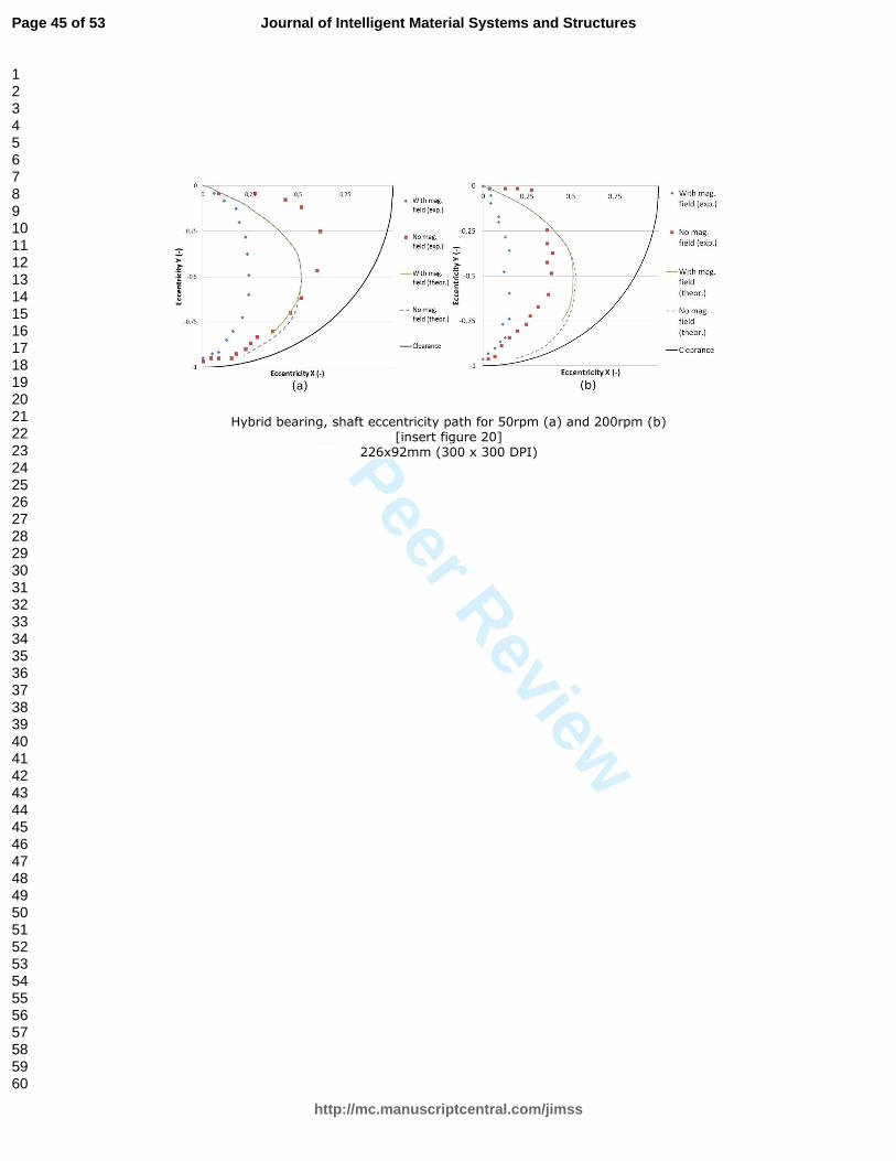
[insert figure 20]
Figure 20 Hybrid bearing, shaft eccentricity path for 50rpm (a) and 200rpm (b).
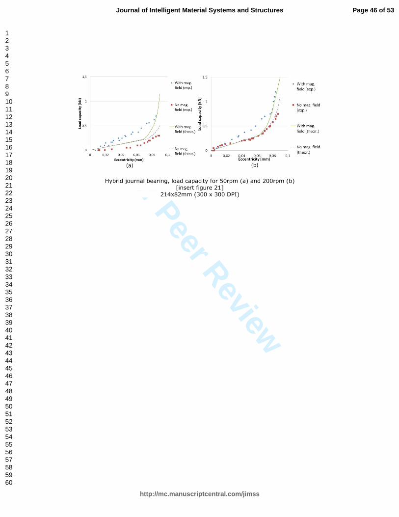
[insert figure 21]
Figure 21 Hybrid journal bearing, load capacity for 50rpm (a) and 200rpm (b).
As shown in Figure 20 and Figure 21, magnetic fluid lubrication improves the
hydrodynamic behaviour, increasing the load capacity and stiffness by at least 50% for
eccentricity values around 0.4< ε <0.7, and the shaft displacement was much more linear
than in classical hydrodynamic bearings, with much lower cross movement.
Second experimental tests were performed to determine the system behaviour working
with active hydrostatic lubrication (four MR valves), using MRF as lubricant (Figure 17).
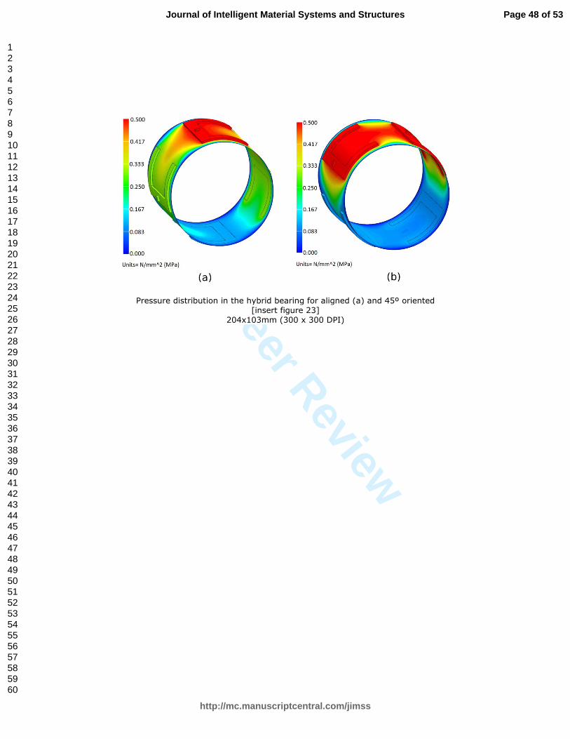
The load was applied in two directions, aligned with the recesses and at 45º, as shown in
Figure 22(a), and with or without rotational speed in Figure 22 (b), hydrostatic or
hydrodynamic. The lubricant pressure achieved in the hybrid bearing for the two
directions is shown in Figure 23(a) and (b).
[insert figure 22]
Figure 22 Hybrid bearing, direction of the applied load (a), pressure graph with or
without rotational velocity (b)
[insert figure 23]
Figure 23 Pressure distribution in the hybrid bearing for aligned (a) and 45º oriented
Page 18 of 53
http://mc.manuscriptcentral.com/jimss
Journal of Intelligent Material Systems and Structures
123456789101112131415161718192021222324252627282930313233343536373839404142434445464748495051525354555657585960
For Peer Review
load (b)
As presented in Figure 24, below a critical load (in function of the force direction) the
stiffness of the active bearing for static loads is quasi-infinite, with typical signal noise
coming from movement of the shaft (unbalance) and monitoring (signal noise), in this
case <+/-5% of clearance. Once critical load is overcome, the stiffness is reduced
dramatically in the case of pure hydrostatic lubrication, and in hybrid condition (200r/min
in the tests) the load can be still increased due to hydrodynamic pressureFigure 24.
Maximum loads were between 600N and 1200N in function of mentioned rotational
velocity and applied force direction. The loads were only presented till eccentricity of
0.75, above that load/displacement the results were not reliable.
[insert figure 24]
Figure 24 Experimental results of active hybrid bearing under load, stationary values.
Time response of active hybrid journal bearing
The system time response was further tested to determine the capability of this active
hybrid journal bearing for compensation of dynamic loads. The tests were carried out
applying a command to the valves and measuring the movement in the shaft, obtaining
the response between current in the coils and the displacement in the shaft.
[insert figure 25]
Figure 25 Experimental results of time response in active hybrid bearing.
As shown in Figure 25, the time constant of both axes was in the range of 0.06-0.07s,
slight differences from hydraulic and experimental set-up. Therefore, the resulting system
bandwidth (3dB point) was below 3Hz. With those values, active control by magnetic
fluids cannot be considered for compensation of higher frequency perturbations. For
Page 19 of 53
http://mc.manuscriptcentral.com/jimss
Journal of Intelligent Material Systems and Structures
123456789101112131415161718192021222324252627282930313233343536373839404142434445464748495051525354555657585960
For Peer Review
example, in grinding or turning spindles the rotational speed is around 2000r/min, and the
compensation of the shaft unbalance would require frequency around 33Hz, more than
ten times higher than available in this system. But the capability to achieve quasi-infinite
stiffness under static loads, and therefore maximum precision in guiding system, was
demonstrated.
Bearing and shaft wear during operation
Finally, the bearing and shaft surface wear were analysed. Magnetic fluids are not
optimal lubricants, since magnetic particles in suspension do not have good friction and
wear properties. The effect in the surface roughness during 1000hr operation in the test
bench was measured in four testing zones, as presented in Figure 26 (a) for bearing and
(b) for the shaft:
[insert figure 26]
Figure 26 Wear and roughness measuring zones, a) bearing and b) shaft.
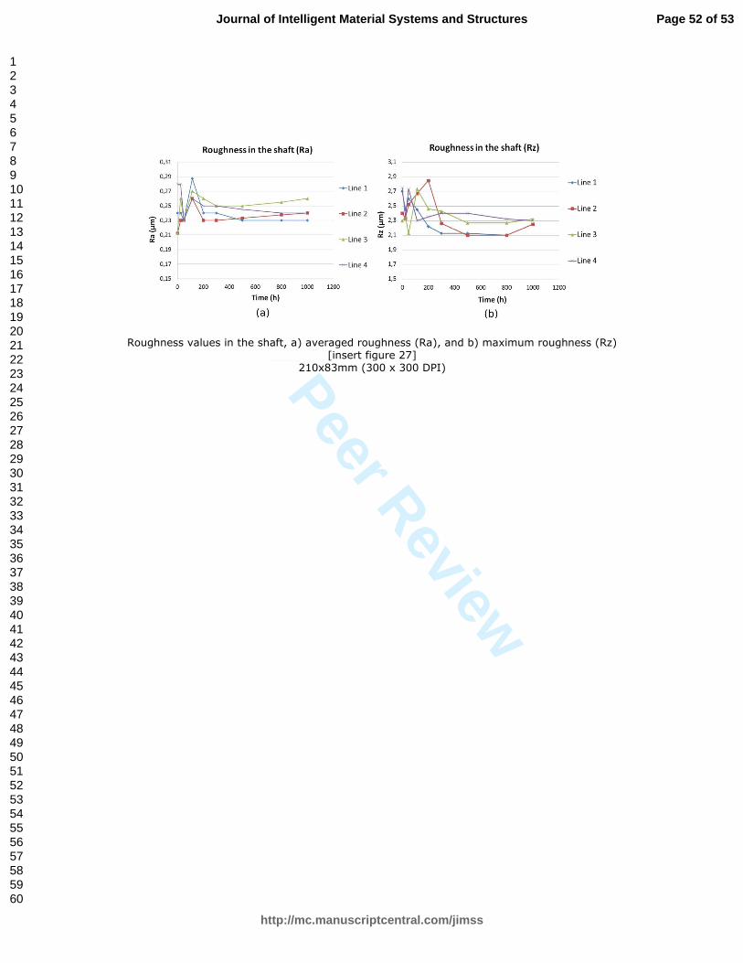
Roughness values (Ra and Rz) of the bearing and the shaft were measured in the long
time test of 1000hr, with periodical measurements, leading to the values presented in
Figure 27:
[insert figure 27]
Figure 27 Roughness values in the shaft, a) averaged roughness (Ra), and b) maximum
roughness (Rz)
[insert figure 28]
Figure 28 Roughness values in the bearing, a) averaged roughness (Ra), and b)
maximum roughness (Rz).
Page 20 of 53
http://mc.manuscriptcentral.com/jimss
Journal of Intelligent Material Systems and Structures
123456789101112131415161718192021222324252627282930313233343536373839404142434445464748495051525354555657585960

For Peer Review
As shown in Figure 27 (a) and (b), the shaft roughness was not altered during the test.
The bearing showed a high roughness in the zone/line labelled as 2, see Error!
Reference source not found. (a) and (b), which was due to a scratch manipulating the
bearing before the test. The roughness in the other three lines had a slight increase, which
could be due to wear caused by magnetic particles in suspension.
CONCLUSIONS
The use of magnetorheological fluids as active elements in hybrid journal bearings
was analysed in this research work. Some prototypes have been developed, and the
validity of simulation models and the final performance of the systems were
demonstrated experimentally.
• A magnetorheological fluid was experimentally analysed, obtaining deeper
information about its behaviour than offered by the manufacturers; as a matter
of fact, for studies in the field of magnetic fluids, such a detailed experimental
characterization is highly recommended.
• Magneto-rheological valves were developed for a full prototype solution in
active bearing lubrication. Good agreement between theoretical values and
experimental results in terms of pressure drop and flowrate was achieved.
• An active hybrid journal bearing was developed, with active hydrodynamic
effect and the use of magnetorheological valves. Hydrodynamic effect was
improved around 50%, while the active hydrostatic lubrication achieved quasi-
infinite static stiffness within a load range.
• Transient response of the active bearing is too slow for dynamic loads with a
bandwidth lower than 5Hz. It cannot be thus used for active compensation of
the unbalance in machine tool spindles shafts.
Page 21 of 53
http://mc.manuscriptcentral.com/jimss
Journal of Intelligent Material Systems and Structures
123456789101112131415161718192021222324252627282930313233343536373839404142434445464748495051525354555657585960

For Peer Review
• Bearing and shaft wear rate was analysed, where a slightly roughness
increment was monitored after 1000hr test in the bearing, and nothing relevant
in the shaft.
REFERENCES
Aguirre, G., Al-Bender, F., Van Brussel, H., 2010. A multiphysics model for optimizing
the design of active aerostatic thrust bearings. Precision Engineering 34, 507–515.
Albers, A., Nguyen, H.T., Burger, W., 2011. Energy efficient hydrodynamic journal
bearing by means of closed loop controlled lubrication flow. Proceedings of
ASME/STLE 2011. Presented at the IJTC2011 International Joint Tribology
Conference, Los Angele, California USA.
Bassani, R., Piccigallo, B., 1992. Hydrostatic Lubrication, Tribology Series. Elsevier,
Pisa University, Italy.
Bin Mazlan, S.A., 2008. The behaviour of magnetorheological fluids in squeeze mode
(Thesis for PhD degree). Dublin City University. School of Mechanical and
Manufacturing Engineering.
Bouzidane, A., Lakis, A.A., Thomas, M., 2008. Nonlinear Dynamic Behavior of a Rigid
Rotor Supported by Hydrostatic Squeeze Film Dampers. J. Tribol. 130, 041102–
041102. doi:10.1115/1.2958079
Deckler, D.C, Veillette R.J., 2004. Simulation and Control of an Active Tilting-Pad
Journal Bearing. Tribology Transactions - TRIBOL TRANS 47, 440–458.
doi:10.1080/05698190490463277
Díaz-Tena, E., Marcaide, L.N.L. de L., Gómez, F.J.C., Bocanegra, D.L.C., 2013. Use of
Magnetorheological Fluids for Vibration Reduction on the Milling of Thin Floor
Parts. Procedia Engineering, The Manufacturing Engineering Society
International Conference, MESIC 2013 63, 835–842.
doi:10.1016/j.proeng.2013.08.252
Dorier, C., Tichy, J., 1992. Behavior of a bingham-like viscous fluid in lubrication flows.
Journal of Non-Newtonian Fluid Mechanics 45, 291–310. doi:10.1016/0377-
0257(92)80065-6
Page 22 of 53
http://mc.manuscriptcentral.com/jimss
Journal of Intelligent Material Systems and Structures
123456789101112131415161718192021222324252627282930313233343536373839404142434445464748495051525354555657585960

For Peer Review
Estupiñan, E.A., Santos, I.F., 2009. Linking rigid multibody systems via controllable thin
fluid films. Tribology International 42, 1478–1486.
doi:10.1016/j.triboint.2009.05.009
Frêne, J., Nicolas, D., Degueurce, B., Berthe, D., Godet, M., 1997. Hydrodynamic
Lubrication: Bearings ans Thurst bearings, Tribology Series. Elsevier, Poitiers,
France.
G. Nikolakopoulos, P., Papadopoulos, C.A., 1998. Controllable high speed journal
bearings, lubricated with electro-rheological fluids. An analytical and
experimental approach. Tribology International 31, 225–234. doi:10.1016/S0301-
679X(98)00025-5
Guldbakke, J.M., Hesselbach, J., 2006. Development of bearings and a damper based on
magnetically controllable fluids. J. Phys.: Condens. Matter 18, S2959.
doi:10.1088/0953-8984/18/38/S29
Hesselbach, J., Abel-Keilhack, C., 2003. Active hydrostatic bearing with
magnetorheological fluid. Journal of Applied Physics 93, 8441–8443.
doi:10.1063/1.1555850
Hsu, T.-C., Chen, J.-H., Chiang, H.-L., Chou, T.-L., 2013. Lubrication performance of
short journal bearings considering the effects of surface roughness and magnetic
field. Tribology International 61, 169–175. doi:10.1016/j.triboint.2012.12.016
Jordan, M.A., 2000. Experimental results and implications of perturbation testing with
servofluid control bearings. Orbit 2nd Quarter, 10–17.
Kuzhir, P.P., Kuzhir, P.G., Gul’kov, G.I., Rudenya, A.L., 2011. Determination of the free
boundary of the lubricant layer of a ferrofluid bearing. J Eng Phys Thermophy 84,
422–429. doi:10.1007/s10891-011-0488-6
Morosi, S., Santos, I.F., 2011. Active lubrication applied to radial gas journal bearings.
Part 1: Modeling. Tribology International 44, 1949–1958.
doi:10.1016/j.triboint.2011.08.007
Nicoletti, R., Santos, I.F., 2008. Control System Design for Flexible Rotors Supported by
Actively Lubricated Bearings. Journal of Vibration and Control 14, 347–374.
doi:10.1177/1077546307080014
Nicoletti, R., Santos, I.F., 2003. Linear and non-linear control techniques applied to
actively lubricated journal bearings. Journal of Sound and Vibration 260, 927–
947. doi:10.1016/S0022-460X(02)00951-3
Odenbach, S., 2002. Magnetoviscous Effects in Ferrofluids, Lecture Notes in Physics.
Springer.
Page 23 of 53
http://mc.manuscriptcentral.com/jimss
Journal of Intelligent Material Systems and Structures
123456789101112131415161718192021222324252627282930313233343536373839404142434445464748495051525354555657585960

For Peer Review
Osman, T.A., 2001. Misalignment Effect on the Static Characteristics of Magnetized
Journal Bearing Lubricated with Ferrofluid. Tribology Letters 11, 195–203.
doi:10.1023/A:1012548624183
Osman, T.A., Nada, G.S., Safar, Z.S., 2001. Effect of Using Current-Carrying-Wire
Models in the Design of Hydrodynamic Journal Bearings Lubricated with
Ferrofluid. Tribology Letters 11, 61–70. doi:10.1023/A:1016657914947
Osman, T.A., Nada, G.S., Safar, Z.S., 2001. Static and dynamic characteristics of
magnetized journal bearings lubricated with ferrofluid. Tribology International
34, 369–380. doi:10.1016/S0301-679X(01)00017-2
Peng, J., Zhu, K.-Q., 2005. Hydrodynamic Characteristics of ER Journal Bearings with
External Electric Field Imposed on the Contractive Part. Journal of Intelligent
Material Systems and Structures 16, 493–499. doi:10.1177/1045389X05052312
Reynolds, O., 1886. On the Theory of Lubrication and Its Application to Mr. Beauchamp
Tower’s Experiments, Including an Experimental Determination of the Viscosity
of Olive Oil. Phil. Trans. R. Soc. Lond. 177, 157–234. doi:10.1098/rstl.1886.0005
Santos, I.F., Watanabe, F.Y., 2006. Lateral dynamics and stability analysis of a gas
compressor supported by hybrid and active lubricated multirecess journal bearing.
Journal of the Brazilian Society of Mechanical Sciences and Engineering 28, 485–
495. doi:10.1590/S1678-58782006000400014
Shamoto, E., Suzuki, N., Hamaguchi, A., 2006. A New Fluid Bearing Utilizing Traveling
Waves. CIRP Annals - Manufacturing Technology 55, 411–414.
doi:10.1016/S0007-8506(07)60447-8
Songjing, L., Guanghuai, W., Dong, C., Songying, L., 2002. New type relief valve using
magneto-rheological fluid.
Spur, G., Patzwald, R., 1998. Lubrication of hydrodynamic journal bearings with
magnetic fluids. Production Engineering - Annals of the German Academic
Society for Production Engineering (WGP) V/1, 47–51.
Sun, L., Krodkiewski, J.M., 1999. Experimental verification of modelling and analysis of
the dynamic properties of an active journal bearing. 10th
World congress onf the
theory of machines and mechanisms, Olulu, Finland.
Tichy, J.A., 1991. Hydrodynamic lubrication theory for the Bingham plastic flow model.
Journal of Rheology 35, 477–496. doi:10.1122/1.550231
Uhlmann, E., Bayat, N., 2003. Applications of ferrofluids in bearings and positioning
system. Production Engineering - Annals of the German Academic Society for
Production Engineering (WGP) 10, 125–128.
Page 24 of 53
http://mc.manuscriptcentral.com/jimss
Journal of Intelligent Material Systems and Structures
123456789101112131415161718192021222324252627282930313233343536373839404142434445464748495051525354555657585960

For Peer Review
Uhlmann, E., Spur, G., Bayat, N., Patzwald, R., 2002. Application of magnetic fluids in
tribotechnical systems. Journal of Magnetism and Magnetic Materials 252, 336–
340. doi:10.1016/S0304-8853(02)00724-2
Urreta, H., Leicht, Z., Sanchez, A., Agirre, A., Kuzhir, P., Magnac, G., 2010.
Hydrodynamic Bearing Lubricated with Magnetic Fluids. Journal of Intelligent
Material Systems and Structures 21, 1491–1499.
doi:10.1177/1045389X09356007
Weck, M., 1984. Handbook of Machine Tools. John Wiley & Sons Ltd, Chichester West
Sussex ; New York.
Page 25 of 53
http://mc.manuscriptcentral.com/jimss
Journal of Intelligent Material Systems and Structures
123456789101112131415161718192021222324252627282930313233343536373839404142434445464748495051525354555657585960

For Peer Review
Hydrodynamic pressure in journal bearing [insert figure 1]
130x157mm (300 x 300 DPI)
Page 26 of 53
http://mc.manuscriptcentral.com/jimss
Journal of Intelligent Material Systems and Structures
123456789101112131415161718192021222324252627282930313233343536373839404142434445464748495051525354555657585960

For Peer Review
Hhybrid journal bearing and hydraulic circuit [insert figure 2]
233x168mm (300 x 300 DPI)
Page 27 of 53
http://mc.manuscriptcentral.com/jimss
Journal of Intelligent Material Systems and Structures
123456789101112131415161718192021222324252627282930313233343536373839404142434445464748495051525354555657585960

For Peer Review
Models for magnetic fluids characterization [insert figure 3]
111x45mm (300 x 300 DPI)
Page 28 of 53
http://mc.manuscriptcentral.com/jimss
Journal of Intelligent Material Systems and Structures
123456789101112131415161718192021222324252627282930313233343536373839404142434445464748495051525354555657585960

For Peer Review
Magnetic characterization of MRF 122–2ED from LORD Corp [insert figure 4]
192x136mm (300 x 300 DPI)
Page 29 of 53
http://mc.manuscriptcentral.com/jimss
Journal of Intelligent Material Systems and Structures
123456789101112131415161718192021222324252627282930313233343536373839404142434445464748495051525354555657585960
For Peer Review
Rheological characterization of MRF, temperature and shear thinning effect [insert figure 5]
201x124mm (300 x 300 DPI)
Page 30 of 53
http://mc.manuscriptcentral.com/jimss
Journal of Intelligent Material Systems and Structures
123456789101112131415161718192021222324252627282930313233343536373839404142434445464748495051525354555657585960

For Peer Review
Rheological characterization of MRF, shear stress and base viscosity [insert figure 6]
179x110mm (300 x 300 DPI)
Page 31 of 53
http://mc.manuscriptcentral.com/jimss
Journal of Intelligent Material Systems and Structures
123456789101112131415161718192021222324252627282930313233343536373839404142434445464748495051525354555657585960

For Peer Review
Balance of forces on a fluid element in the plug region, MRF lubrication [insert figure 7]
63x28mm (300 x 300 DPI)
Page 32 of 53
http://mc.manuscriptcentral.com/jimss
Journal of Intelligent Material Systems and Structures
123456789101112131415161718192021222324252627282930313233343536373839404142434445464748495051525354555657585960

For Peer Review
Velocity distribution in a MRF under magnetic field with plug region (III) [insert figure 8]
57x37mm (300 x 300 DPI)
Page 33 of 53
http://mc.manuscriptcentral.com/jimss
Journal of Intelligent Material Systems and Structures
123456789101112131415161718192021222324252627282930313233343536373839404142434445464748495051525354555657585960
For Peer Review
Pressure distribution (a) and gradient (b) into a journal bearing, solution in 3D graph [insert figure 9]
131x39mm (300 x 300 DPI)
Page 34 of 53
http://mc.manuscriptcentral.com/jimss
Journal of Intelligent Material Systems and Structures
123456789101112131415161718192021222324252627282930313233343536373839404142434445464748495051525354555657585960

For Peer Review
CFD simulations of MR valve, pressure drop (a) and flow-rate calculation (b [insert figure 10]
205x76mm (300 x 300 DPI)
Page 35 of 53
http://mc.manuscriptcentral.com/jimss
Journal of Intelligent Material Systems and Structures
123456789101112131415161718192021222324252627282930313233343536373839404142434445464748495051525354555657585960

For Peer Review
Magnetic simulation of MR valve (a) and magnetic field in control points (b) [insert figure 11]
173x61mm (300 x 300 DPI)
Page 36 of 53
http://mc.manuscriptcentral.com/jimss
Journal of Intelligent Material Systems and Structures
123456789101112131415161718192021222324252627282930313233343536373839404142434445464748495051525354555657585960

For Peer Review
MR valve for hybrid bearing, design sketches (a) and working principle (b) [insert figure 12]
190x107mm (300 x 300 DPI)
Page 37 of 53
http://mc.manuscriptcentral.com/jimss
Journal of Intelligent Material Systems and Structures
123456789101112131415161718192021222324252627282930313233343536373839404142434445464748495051525354555657585960

For Peer Review
MR valves picture with description of parts [insert figure 13]
147x80mm (300 x 300 DPI)
Page 38 of 53
http://mc.manuscriptcentral.com/jimss
Journal of Intelligent Material Systems and Structures
123456789101112131415161718192021222324252627282930313233343536373839404142434445464748495051525354555657585960
For Peer Review
Sketch of hybrid journal bearing test bench and prototype [insert figure 14]
166x91mm (300 x 300 DPI)
Page 39 of 53
http://mc.manuscriptcentral.com/jimss
Journal of Intelligent Material Systems and Structures
123456789101112131415161718192021222324252627282930313233343536373839404142434445464748495051525354555657585960

For Peer Review
Hybrid journal bearing test bench, overall view [insert figure 15]
180x99mm (300 x 300 DPI)
Page 40 of 53
http://mc.manuscriptcentral.com/jimss
Journal of Intelligent Material Systems and Structures
123456789101112131415161718192021222324252627282930313233343536373839404142434445464748495051525354555657585960

For Peer Review
Hybrid journal bearing prototype, bearing house section view and dimensions [insert figure 16]
221x86mm (300 x 300 DPI)
Page 41 of 53
http://mc.manuscriptcentral.com/jimss
Journal of Intelligent Material Systems and Structures
123456789101112131415161718192021222324252627282930313233343536373839404142434445464748495051525354555657585960

For Peer Review
Active hybrid journal bearings hydraulic circuit and control [insert figure 17]
138x64mm (300 x 300 DPI)
Page 42 of 53
http://mc.manuscriptcentral.com/jimss
Journal of Intelligent Material Systems and Structures
123456789101112131415161718192021222324252627282930313233343536373839404142434445464748495051525354555657585960

For Peer Review
Experimental and theoretical results in the MR valve for active bearing [insert figure 18]
231x152mm (300 x 300 DPI)
Page 43 of 53
http://mc.manuscriptcentral.com/jimss
Journal of Intelligent Material Systems and Structures
123456789101112131415161718192021222324252627282930313233343536373839404142434445464748495051525354555657585960
For Peer Review
Magnetic field in the hybrid bearing (a), and field strength in the gap (b) for cutting plane defined by (b), half cylinder
[insert figure 19]
190x80mm (300 x 300 DPI)
Page 44 of 53
http://mc.manuscriptcentral.com/jimss
Journal of Intelligent Material Systems and Structures
123456789101112131415161718192021222324252627282930313233343536373839404142434445464748495051525354555657585960
For Peer Review
Hybrid bearing, shaft eccentricity path for 50rpm (a) and 200rpm (b) [insert figure 20]
226x92mm (300 x 300 DPI)
Page 45 of 53
http://mc.manuscriptcentral.com/jimss
Journal of Intelligent Material Systems and Structures
123456789101112131415161718192021222324252627282930313233343536373839404142434445464748495051525354555657585960
For Peer Review
Hybrid journal bearing, load capacity for 50rpm (a) and 200rpm (b) [insert figure 21]
214x82mm (300 x 300 DPI)
Page 46 of 53
http://mc.manuscriptcentral.com/jimss
Journal of Intelligent Material Systems and Structures
123456789101112131415161718192021222324252627282930313233343536373839404142434445464748495051525354555657585960

For Peer Review
Hybrid bearing, direction of the applied load (a), pressure graph with or without rotational velocity (b) [insert figure 22]
188x90mm (300 x 300 DPI)
Page 47 of 53
http://mc.manuscriptcentral.com/jimss
Journal of Intelligent Material Systems and Structures
123456789101112131415161718192021222324252627282930313233343536373839404142434445464748495051525354555657585960
For Peer Review
Pressure distribution in the hybrid bearing for aligned (a) and 45º oriented [insert figure 23]
204x103mm (300 x 300 DPI)
Page 48 of 53
http://mc.manuscriptcentral.com/jimss
Journal of Intelligent Material Systems and Structures
123456789101112131415161718192021222324252627282930313233343536373839404142434445464748495051525354555657585960

For Peer Review
Experimental results of active hybrid bearing under load, stationary values [insert figure 24]
198x147mm (300 x 300 DPI)
Page 49 of 53
http://mc.manuscriptcentral.com/jimss
Journal of Intelligent Material Systems and Structures
123456789101112131415161718192021222324252627282930313233343536373839404142434445464748495051525354555657585960

For Peer Review
Experimental results of time response in active hybrid bearing [insert figure 25]
184x129mm (300 x 300 DPI)
Page 50 of 53
http://mc.manuscriptcentral.com/jimss
Journal of Intelligent Material Systems and Structures
123456789101112131415161718192021222324252627282930313233343536373839404142434445464748495051525354555657585960

For Peer Review
Wear and roughness measuring zones, a) bearing and b) shaft [insert figure 26]
72x30mm (300 x 300 DPI)
Page 51 of 53
http://mc.manuscriptcentral.com/jimss
Journal of Intelligent Material Systems and Structures
123456789101112131415161718192021222324252627282930313233343536373839404142434445464748495051525354555657585960
For Peer Review
Roughness values in the shaft, a) averaged roughness (Ra), and b) maximum roughness (Rz) [insert figure 27]
210x83mm (300 x 300 DPI)
Page 52 of 53
http://mc.manuscriptcentral.com/jimss
Journal of Intelligent Material Systems and Structures
123456789101112131415161718192021222324252627282930313233343536373839404142434445464748495051525354555657585960

For Peer Review
Roughness values in the bearing, a) averaged roughness (Ra), and b) maximum roughness (Rz) [insert figure 28]
178x68mm (300 x 300 DPI)
Page 53 of 53
http://mc.manuscriptcentral.com/jimss
Journal of Intelligent Material Systems and Structures
123456789101112131415161718192021222324252627282930313233343536373839404142434445464748495051525354555657585960