activity booklet of fischertechnik robo tx explorer
DESCRIPTION
The Activity Booklet of fischertechnik Robotics ROBO TX ExplorerTRANSCRIPT

○ ○ ○ ○ ○ ○ ○ ○ ○ ○ ○ ○ ○ ○ ○ ○ ○ ○ ○ ○ ○ ○ ○ ○ ○ ○ ○ ○ ○ ○ ○ ○ ○ ○ ○ ○ ○ ○ ○ ○ ○ ○ ○ ○ ○ ○ ○ ○ ○ ○ ○ ○ ○ ○ ○ ○ ○ ○ ○ ○ ○ ○ ○
R O B OR O B OR O B OR O B OR O B O TX TX TX TX TX EEEEE X P L O R EX P L O R EX P L O R EX P L O R EX P L O R E RRRRR AAAAA C T I V I T YC T I V I T YC T I V I T YC T I V I T YC T I V I T Y B B B B B O O K L E TO O K L E TO O K L E TO O K L E TO O K L E T
17
○ ○ ○ ○ ○ ○ ○ ○ ○ ○ ○ ○ ○ ○ ○ ○ ○ ○ ○ ○ ○ ○ ○ ○ ○ ○ ○ ○ ○ ○ ○ ○ ○ ○ ○ ○ ○ ○ ○ ○ ○ ○ ○ ○ ○ ○ ○
Vehicles with Crawler Drive p. 18
○ ○ ○ ○ ○ ○ ○ ○ ○ ○ ○ ○ ○ ○ ○ ○ ○ ○ ○ ○ ○ ○ ○ ○ ○ ○ ○ ○ ○ ○ ○ ○ ○ ○ ○ ○ ○ ○ ○ ○ ○
The Steering p. 18
○ ○ ○ ○ ○ ○ ○ ○ ○ ○ ○ ○ ○ ○ ○ ○ ○ ○ ○ ○ ○ ○ ○ ○ ○ ○ ○ ○ ○ ○ ○ ○ ○ ○ ○ ○ ○ ○ ○ ○ ○
Explorer Model from fischertechnik p. 19
○ ○ ○ ○ ○ ○ ○ ○ ○ ○ ○ ○ ○ ○ ○ ○ ○ ○ ○ ○ ○ ○ ○ ○ ○ ○ ○ ○ ○ ○ ○ ○ ○ ○ ○ ○ ○ ○ ○ ○ ○
Actuators p. 19
○ ○ ○ ○ ○ ○ ○ ○ ○ ○ ○ ○ ○ ○ ○ ○ ○ ○ ○ ○ ○ ○ ○ ○ ○ ○ ○ ○ ○ ○ ○ ○ ○ ○ ○ ○ ○ ○ ○ ○ ○
Sensors p. 20
○ ○ ○ ○ ○ ○ ○ ○ ○ ○ ○ ○ ○ ○ ○ ○ ○ ○ ○ ○ ○ ○ ○ ○ ○ ○ ○ ○ ○ ○ ○ ○ ○ ○ ○ ○ ○ ○ ○ ○ ○
ROBO TX Controller p. 21
○ ○ ○ ○ ○ ○ ○ ○ ○ ○ ○ ○ ○ ○ ○ ○ ○ ○ ○ ○ ○ ○ ○ ○ ○ ○ ○ ○ ○ ○ ○ ○ ○ ○ ○ ○ ○ ○ ○ ○ ○
Power Supply p. 21
○ ○ ○ ○ ○ ○ ○ ○ ○ ○ ○ ○ ○ ○ ○ ○ ○ ○ ○ ○ ○ ○ ○ ○ ○ ○ ○ ○ ○ ○ ○ ○ ○ ○ ○ ○ ○ ○ ○ ○ ○
Software ROBO Pro p. 21
○ ○ ○ ○ ○ ○ ○ ○ ○ ○ ○ ○ ○ ○ ○ ○ ○ ○ ○ ○ ○ ○ ○ ○ ○ ○ ○ ○ ○ ○ ○ ○ ○ ○ ○ ○ ○ ○ ○ ○ ○ ○ ○ ○ ○ ○ ○
Preliminary Considerations p. 22
○ ○ ○ ○ ○ ○ ○ ○ ○ ○ ○ ○ ○ ○ ○ ○ ○ ○ ○ ○ ○ ○ ○ ○ ○ ○ ○ ○ ○ ○ ○ ○ ○ ○ ○ ○ ○ ○ ○ ○ ○ ○ ○ ○ ○ ○ ○
Basics of the ROBO TX Controller p. 22
○ ○ ○ ○ ○ ○ ○ ○ ○ ○ ○ ○ ○ ○ ○ ○ ○ ○ ○ ○ ○ ○ ○ ○ ○ ○ ○ ○ ○ ○ ○ ○ ○ ○ ○ ○ ○ ○ ○ ○ ○ ○ ○ ○ ○ ○ ○
The Basic Model p. 23
○ ○ ○ ○ ○ ○ ○ ○ ○ ○ ○ ○ ○ ○ ○ ○ ○ ○ ○ ○ ○ ○ ○ ○ ○ ○ ○ ○ ○ ○ ○ ○ ○ ○ ○ ○ ○ ○ ○ ○ ○
Basic Program p. 23
○ ○ ○ ○ ○ ○ ○ ○ ○ ○ ○ ○ ○ ○ ○ ○ ○ ○ ○ ○ ○ ○ ○ ○ ○ ○ ○ ○ ○ ○ ○ ○ ○ ○ ○ ○ ○ ○ ○ ○ ○
Encoder Motors p. 24
○ ○ ○ ○ ○ ○ ○ ○ ○ ○ ○ ○ ○ ○ ○ ○ ○ ○ ○ ○ ○ ○ ○ ○ ○ ○ ○ ○ ○ ○ ○ ○ ○ ○ ○ ○ ○ ○ ○ ○ ○
Subprograms p. 24
○ ○ ○ ○ ○ ○ ○ ○ ○ ○ ○ ○ ○ ○ ○ ○ ○ ○ ○ ○ ○ ○ ○ ○ ○ ○ ○ ○ ○ ○ ○ ○ ○ ○ ○ ○ ○ ○ ○ ○ ○ ○ ○ ○ ○ ○ ○
Autonomous Tracked Vehicles p. 25
○ ○ ○ ○ ○ ○ ○ ○ ○ ○ ○ ○ ○ ○ ○ ○ ○ ○ ○ ○ ○ ○ ○ ○ ○ ○ ○ ○ ○ ○ ○ ○ ○ ○ ○ ○ ○ ○ ○ ○ ○
Trail Searcher p. 25
○ ○ ○ ○ ○ ○ ○ ○ ○ ○ ○ ○ ○ ○ ○ ○ ○ ○ ○ ○ ○ ○ ○ ○ ○ ○ ○ ○ ○ ○ ○ ○ ○ ○ ○ ○ ○ ○ ○ ○ ○
Tunnel Robot p. 28
○ ○ ○ ○ ○ ○ ○ ○ ○ ○ ○ ○ ○ ○ ○ ○ ○ ○ ○ ○ ○ ○ ○ ○ ○ ○ ○ ○ ○ ○ ○ ○ ○ ○ ○ ○ ○ ○ ○ ○ ○
Color Detector p. 29
○ ○ ○ ○ ○ ○ ○ ○ ○ ○ ○ ○ ○ ○ ○ ○ ○ ○ ○ ○ ○ ○ ○ ○ ○ ○ ○ ○ ○ ○ ○ ○ ○ ○ ○ ○ ○ ○ ○ ○ ○
Explorer p. 30
○ ○ ○ ○ ○ ○ ○ ○ ○ ○ ○ ○ ○ ○ ○ ○ ○ ○ ○ ○ ○ ○ ○ ○ ○ ○ ○ ○ ○ ○ ○ ○ ○ ○ ○ ○ ○ ○ ○ ○ ○ ○ ○ ○ ○ ○ ○
RoboCupJunior – Rescue Robot p. 32
○ ○ ○ ○ ○ ○ ○ ○ ○ ○ ○ ○ ○ ○ ○ ○ ○ ○ ○ ○ ○ ○ ○ ○ ○ ○ ○ ○ ○ ○ ○ ○ ○ ○ ○ ○ ○ ○ ○ ○ ○ ○ ○ ○ ○ ○ ○
Important Tips p. 32
Contents

○ ○ ○ ○ ○ ○ ○ ○ ○ ○ ○ ○ ○ ○ ○ ○ ○ ○ ○ ○ ○ ○ ○ ○ ○ ○ ○ ○ ○ ○ ○ ○ ○ ○ ○ ○ ○ ○ ○ ○ ○ ○ ○ ○ ○ ○ ○ ○ ○ ○ ○ ○ ○ ○ ○ ○ ○ ○ ○ ○ ○ ○ ○
R O B OR O B OR O B OR O B OR O B O TX TX TX TX TX EEEEE X P L O R EX P L O R EX P L O R EX P L O R EX P L O R E RRRRR AAAAA C T I V I T YC T I V I T YC T I V I T YC T I V I T YC T I V I T Y B B B B B O O K L E TO O K L E TO O K L E TO O K L E TO O K L E T
18
Vehicles with
Crawler Drive
The Steering
■ Why are autonomous vehicles with a crawler drive needed? The invention of the crawler drive forvehicles was necessary in order to be able to travel over very difficult terrain. The crawler drive was usedin areas such as the desert where a wheel drive could not travel. For example, in the First World War, thefirst trucks and tanks with a crawler drive were built and employed.
Depending on the terrain, the vehicles could be converted from a wheel drive to crawler drive.
Tracked vehicles were also used in the civilian area. As you can see from the pictures, wheel-drivenvehicles were actually always the basis for tracked vehicles.
But it didn’t take long to determine a weak point: The steerable front wheels. Therefore, the crawler drivewas expanded and used for all axles.
■ But then how did the steering work? Very simple, through the slowing or speeding up of one of the twotracks. If a turn to the right was to be made, the right track was slowed down by using a control stick, oneper track. When this was done, this track moved slower and thus the vehicle moved to the right.
Even today, of course with the state of the art technology, youstill find many vehicles, which use the crawler drive. Theserange from small excavators to the giants for the open pit miningof brown coal.
In the Cheops Pyramid in Egypt, a minirobot was used to helpfind the trail of more secrets.
The researchers sent the robot, which was about the size of atoy locomotive, through a dark narrow shaft. It led upwardsfrom a chamber in the center of the pyramid, which was 4500years old, and ended in front of a mysterious stone door.

○ ○ ○ ○ ○ ○ ○ ○ ○ ○ ○ ○ ○ ○ ○ ○ ○ ○ ○ ○ ○ ○ ○ ○ ○ ○ ○ ○ ○ ○ ○ ○ ○ ○ ○ ○ ○ ○ ○ ○ ○ ○ ○ ○ ○ ○ ○ ○ ○ ○ ○ ○ ○ ○ ○ ○ ○ ○ ○ ○ ○ ○ ○
R O B OR O B OR O B OR O B OR O B O TX TX TX TX TX EEEEE X P L O R EX P L O R EX P L O R EX P L O R EX P L O R E RRRRR AAAAA C T I V I T YC T I V I T YC T I V I T YC T I V I T YC T I V I T Y B B B B B O O K L E TO O K L E TO O K L E TO O K L E TO O K L E T
19
Explorer Model
from
fischertechnik
Actuators
■ Explore unknown areas, measure distances, follow trails, show directions of travel by means of blinkingsignals, recognize colors, measure temperatures, avoid obstacles without touching them, recognize dayand night, turn headlights on and off automatically and trigger an alarm etc. The ROBO TX Explorer sensorscan do all of this and lots more. More specifically this includes: The NTC resistor, the photoresistor, theultrasonic distance sensor, the optical color sensor and the specially developed infrared trail sensor. Thanksto two encoder motors and the crawler drive even almost impassable terrain can be explored and traveledon. With the rescue robot, which is contained as a model, the construction set provides the ideal basis forparticipation in the RoboCupJunior.
Now, before you get started, you should become familiar with the most important components. These aredescribed in the following:
Encoder MotorWe use the two encoder motors, which are contained in the construction set, as the drive for our robots.At first glance, these are normal electric motors, which are designed for a voltage of nine volts and currentinput of a maximum of 0.5 amperes.
However, the encoder motors can do even more than this: In addition to the connection for the powersupply for the motor, they have another jack socket for a three-pin connection cable and through this andwith the aid of what is called the encoder, the rotational movement of the motor can be evaluated.
Thus, the encoder functions similar to the speedometer on a bicycle. A magnet (in most cases for a bicyclelocated on one of the spokes) passes by a sensor (attached to the fork of the bicycle in most cases) witheach revolution and the sensor generates a pulse due to this. These pulses can be counted, and, forexample, multiplied with the circumference of the tire for the speedometer. In this way, the distancetraveled is obtained.
The encoders on the fischertechnik encoder motors generate three pulses with each revolution of themotor shaft. And because the encoder motors also have a gearbox with a transmission ratio of 25:1(meaning „25 to 1“), then one revolution of the shaft, which comes out of the gearbox, corresponds to 75pulses of the encoder.
The encoder motors are connected to the outputs M1 to M4 on the ROBO TX Controller. The encodersignals are read in through the inputs C1 to C4.
BuzzerThe buzzer is used, for example, to acoustically report obstacles or colors, which are identified. This is alsoconnected to the outputs M1 to M4.
Bulb LampThis is a bulb for a voltage of nine volts. This can be used as a status signal for the direction of travel orsimply for illumination. This is connected to the outputs M1 to M4.
○ ○ ○ ○ ○ ○ ○ ○ ○ ○ ○ ○ ○ ○ ○ ○ ○ ○ ○ ○ ○ ○ ○ ○ ○ ○ ○ ○ ○ ○ ○ ○ ○ ○ ○ ○ ○ ○ ○ ○ ○ ○ ○ ○ ○ ○ ○ ○ ○ ○ ○ ○ ○ ○ ○ ○ ○ ○ ○ ○ ○ ○ ○
R O B OR O B OR O B OR O B OR O B O TX TX TX TX TX EEEEE X P L O R EX P L O R EX P L O R EX P L O R EX P L O R E RRRRR AAAAA C T I V I T YC T I V I T YC T I V I T YC T I V I T YC T I V I T Y B B B B B O O K L E TO O K L E TO O K L E TO O K L E TO O K L E T
20
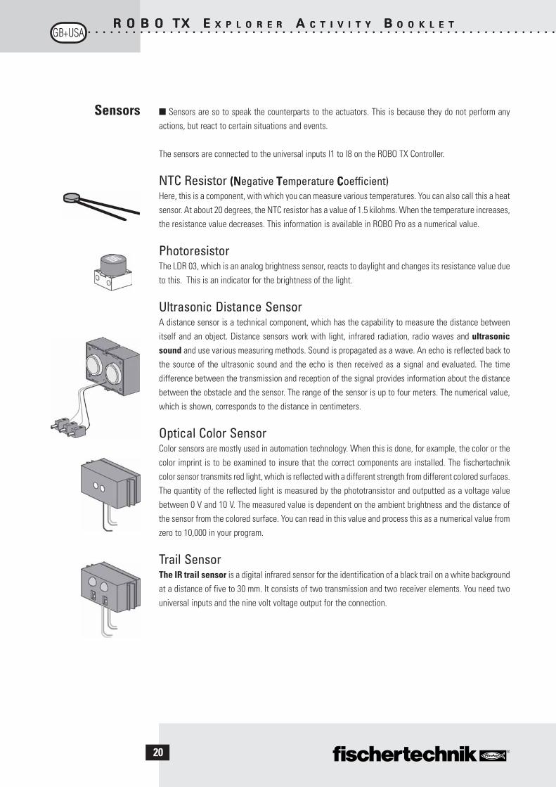
■ Sensors are so to speak the counterparts to the actuators. This is because they do not perform anyactions, but react to certain situations and events.
The sensors are connected to the universal inputs I1 to I8 on the ROBO TX Controller.
NTC Resistor (N (N (N (N (Negative TTTTTemperature CCCCCoefficient)Here, this is a component, with which you can measure various temperatures. You can also call this a heatsensor. At about 20 degrees, the NTC resistor has a value of 1.5 kilohms. When the temperature increases,the resistance value decreases. This information is available in ROBO Pro as a numerical value.
PhotoresistorThe LDR 03, which is an analog brightness sensor, reacts to daylight and changes its resistance value dueto this. This is an indicator for the brightness of the light.
Ultrasonic Distance SensorA distance sensor is a technical component, which has the capability to measure the distance betweenitself and an object. Distance sensors work with light, infrared radiation, radio waves and ultrasonicsound and use various measuring methods. Sound is propagated as a wave. An echo is reflected back tothe source of the ultrasonic sound and the echo is then received as a signal and evaluated. The timedifference between the transmission and reception of the signal provides information about the distancebetween the obstacle and the sensor. The range of the sensor is up to four meters. The numerical value,which is shown, corresponds to the distance in centimeters.
Optical Color SensorColor sensors are mostly used in automation technology. When this is done, for example, the color or thecolor imprint is to be examined to insure that the correct components are installed. The fischertechnikcolor sensor transmits red light, which is reflected with a different strength from different colored surfaces.The quantity of the reflected light is measured by the phototransistor and outputted as a voltage valuebetween 0 V and 10 V. The measured value is dependent on the ambient brightness and the distance ofthe sensor from the colored surface. You can read in this value and process this as a numerical value fromzero to 10,000 in your program.
Trail SensorThe IR trail sensor is a digital infrared sensor for the identification of a black trail on a white backgroundat a distance of five to 30 mm. It consists of two transmission and two receiver elements. You need twouniversal inputs and the nine volt voltage output for the connection.
Sensors

○ ○ ○ ○ ○ ○ ○ ○ ○ ○ ○ ○ ○ ○ ○ ○ ○ ○ ○ ○ ○ ○ ○ ○ ○ ○ ○ ○ ○ ○ ○ ○ ○ ○ ○ ○ ○ ○ ○ ○ ○ ○ ○ ○ ○ ○ ○ ○ ○ ○ ○ ○ ○ ○ ○ ○ ○ ○ ○ ○ ○ ○ ○
R O B OR O B OR O B OR O B OR O B O TX TX TX TX TX EEEEE X P L O R EX P L O R EX P L O R EX P L O R EX P L O R E RRRRR AAAAA C T I V I T YC T I V I T YC T I V I T YC T I V I T YC T I V I T Y B B B B B O O K L E TO O K L E TO O K L E TO O K L E TO O K L E T
21
■ The most important component for building a tracked vehicle is the ROBO TX Controller, which isinstalled as a fixed element in the various models. You can connect your sensors and actuators to this asneeded. You can find the basic wiring in the enclosed assembly instructions.
■ The ROBO TX Explorer models are autonomous vehicles, which move freely in the area. Therefore, youuse the fischertechnik rechargeable battery set as the power supply.
■ ROBO Pro is a simple graphic programing interface, with which you can write your programs. The advantageis that you don’t have to learn any programing language. Actually, you can start right now.
You need the ROBO Pro version 2.1.4.2 for the construction set, ROBO TX Explorer. If youhave an older version of the software, you can update this at no charge. Download thiswith the help menu in ROBO Pro-Download New Version-or at:
www.fischertechnik.de/robopro/update.html.
ROBO TX
Controller
Power Supply
Software ROBO Pro

○ ○ ○ ○ ○ ○ ○ ○ ○ ○ ○ ○ ○ ○ ○ ○ ○ ○ ○ ○ ○ ○ ○ ○ ○ ○ ○ ○ ○ ○ ○ ○ ○ ○ ○ ○ ○ ○ ○ ○ ○ ○ ○ ○ ○ ○ ○ ○ ○ ○ ○ ○ ○ ○ ○ ○ ○ ○ ○ ○ ○ ○ ○
R O B OR O B OR O B OR O B OR O B O TX TX TX TX TX EEEEE X P L O R EX P L O R EX P L O R EX P L O R EX P L O R E RRRRR AAAAA C T I V I T YC T I V I T YC T I V I T YC T I V I T YC T I V I T Y B B B B B O O K L E TO O K L E TO O K L E TO O K L E TO O K L E T
22
Preliminary
Considerations
Basics of the
ROBO TX
Controller
■ As for all other fischertechnik robots, with the ROBO TX Explorer, you will be introduced step-by-step tothe fascination of technology and programing. You start with a simple model and work your way forwardsto increasingly more comprehensive systems with fascinating possibilities. The primary focus for all modelsis the precise construction and precise placing in operation.
■ Before you start with the individual models, you should become familiar with the Controller with thehelp of some experiments. If you have problems, you can also find information in the ROBO Pro help.
After you have installed the software, you can connect the Controller using the cable, whichis supplied, to your PC. Now, start the ROBO Pro program and open the window for theinterface test with the Test button.
Encoder MotorConnect the connections of the encoder motor with theconnection M1. Click with the mouse on the selection„Counterclockwise“ or „Clockwise.“ The motor starts withits maximum speed. By operating the control, you canadjust the RPMs. Use „Stop“ to stop the action.
PhotoresistorConnect the photoresistor, which is provided, to theconnection I1 and set the input to „Analog 5 kOhm (NTC, . . .).“Change the luminous intensity of the photoresistor by slowly covering with a black strip of paper. Whathappens? You will see that this changes the numerical value of the input.
The interface test is explained very well in chapter 2 of the ROBO Pro help. You can also find help if thereare problems between your computer and the Controller and the software – take a look, it´s worth it!
○ ○ ○ ○ ○ ○ ○ ○ ○ ○ ○ ○ ○ ○ ○ ○ ○ ○ ○ ○ ○ ○ ○ ○ ○ ○ ○ ○ ○ ○ ○ ○ ○ ○ ○ ○ ○ ○ ○ ○ ○ ○ ○ ○ ○ ○ ○ ○ ○ ○ ○ ○ ○ ○ ○ ○ ○ ○ ○ ○ ○ ○ ○
R O B OR O B OR O B OR O B OR O B O TX TX TX TX TX EEEEE X P L O R EX P L O R EX P L O R EX P L O R EX P L O R E RRRRR AAAAA C T I V I T YC T I V I T YC T I V I T YC T I V I T YC T I V I T Y B B B B B O O K L E TO O K L E TO O K L E TO O K L E TO O K L E T
23
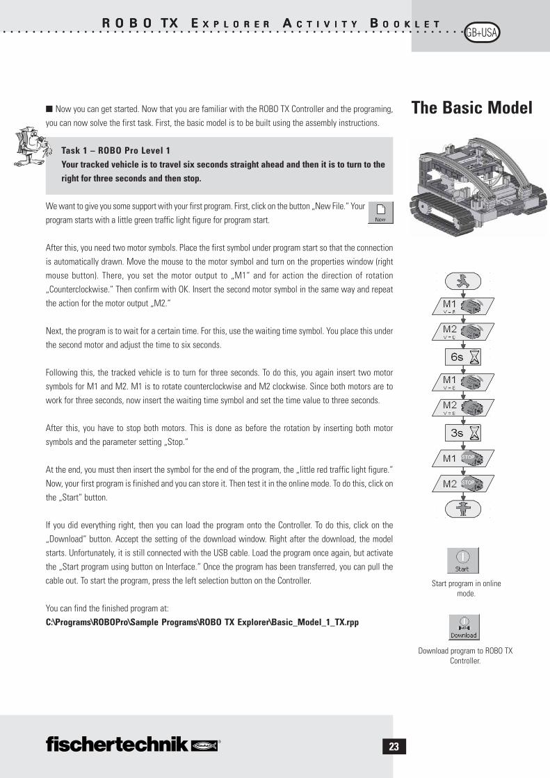
■ Now you can get started. Now that you are familiar with the ROBO TX Controller and the programing,you can now solve the first task. First, the basic model is to be built using the assembly instructions.
Task 1 – ROBO Pro Level 1Your tracked vehicle is to travel six seconds straight ahead and then it is to turn to theright for three seconds and then stop.
We want to give you some support with your first program. First, click on the button „New File.“ Yourprogram starts with a little green traffic light figure for program start.
After this, you need two motor symbols. Place the first symbol under program start so that the connectionis automatically drawn. Move the mouse to the motor symbol and turn on the properties window (rightmouse button). There, you set the motor output to „M1“ and for action the direction of rotation„Counterclockwise.“ Then confirm with OK. Insert the second motor symbol in the same way and repeatthe action for the motor output „M2.“
Next, the program is to wait for a certain time. For this, use the waiting time symbol. You place this underthe second motor and adjust the time to six seconds.
Following this, the tracked vehicle is to turn for three seconds. To do this, you again insert two motorsymbols for M1 and M2. M1 is to rotate counterclockwise and M2 clockwise. Since both motors are towork for three seconds, now insert the waiting time symbol and set the time value to three seconds.
After this, you have to stop both motors. This is done as before the rotation by inserting both motorsymbols and the parameter setting „Stop.“
At the end, you must then insert the symbol for the end of the program, the „little red traffic light figure.“Now, your first program is finished and you can store it. Then test it in the online mode. To do this, click onthe „Start“ button.
If you did everything right, then you can load the program onto the Controller. To do this, click on the„Download“ button. Accept the setting of the download window. Right after the download, the modelstarts. Unfortunately, it is still connected with the USB cable. Load the program once again, but activatethe „Start program using button on Interface.“ Once the program has been transferred, you can pull thecable out. To start the program, press the left selection button on the Controller.
You can find the finished program at:C:\Programs\ROBOPro\Sample Programs\ROBO TX Explorer\Basic_Model_1_TX.rpp
Download program to ROBO TXController.
Start program in onlinemode.
The Basic Model
○ ○ ○ ○ ○ ○ ○ ○ ○ ○ ○ ○ ○ ○ ○ ○ ○ ○ ○ ○ ○ ○ ○ ○ ○ ○ ○ ○ ○ ○ ○ ○ ○ ○ ○ ○ ○ ○ ○ ○ ○ ○ ○ ○ ○ ○ ○ ○ ○ ○ ○ ○ ○ ○ ○ ○ ○ ○ ○ ○ ○ ○ ○
R O B OR O B OR O B OR O B OR O B O TX TX TX TX TX EEEEE X P L O R EX P L O R EX P L O R EX P L O R EX P L O R E RRRRR AAAAA C T I V I T YC T I V I T YC T I V I T YC T I V I T YC T I V I T Y B B B B B O O K L E TO O K L E TO O K L E TO O K L E TO O K L E T
24
Encoder Motors
Subprograms
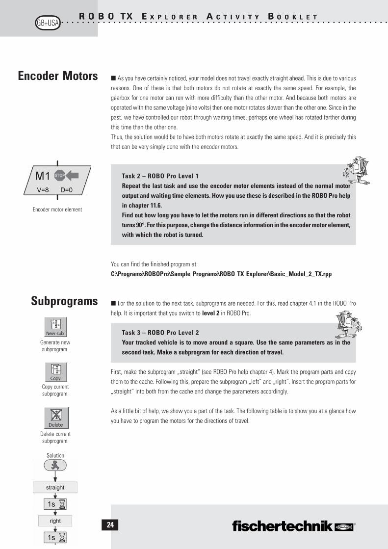
■ As you have certainly noticed, your model does not travel exactly straight ahead. This is due to variousreasons. One of these is that both motors do not rotate at exactly the same speed. For example, thegearbox for one motor can run with more difficulty than the other motor. And because both motors areoperated with the same voltage (nine volts) then one motor rotates slower than the other one. Since in thepast, we have controlled our robot through waiting times, perhaps one wheel has rotated farther duringthis time than the other one.Thus, the solution would be to have both motors rotate at exactly the same speed. And it is precisely thisthat can be very simply done with the encoder motors.
Task 2 – ROBO Pro Level 1Repeat the last task and use the encoder motor elements instead of the normal motoroutput and waiting time elements. How you use these is described in the ROBO Pro helpin chapter 11.6.Find out how long you have to let the motors run in different directions so that the robotturns 90°. For this purpose, change the distance information in the encoder motor element,with which the robot is turned.
You can find the finished program at:C:\Programs\ROBOPro\Sample Programs\ROBO TX Explorer\Basic_Model_2_TX.rpp
■ For the solution to the next task, subprograms are needed. For this, read chapter 4.1 in the ROBO Prohelp. It is important that you switch to level 2 in ROBO Pro.
Task 3 – ROBO Pro Level 2Your tracked vehicle is to move around a square. Use the same parameters as in thesecond task. Make a subprogram for each direction of travel.
First, make the subprogram „straight“ (see ROBO Pro help chapter 4). Mark the program parts and copythem to the cache. Following this, prepare the subprogram „left“ and „right“. Insert the program parts for„straight“ into both from the cache and change the parameters accordingly.
As a little bit of help, we show you a part of the task. The following table is to show you at a glance howyou have to program the motors for the directions of travel.
Encoder motor element
Solution
Copy currentsubprogram.
Generate newsubprogram.
Delete currentsubprogram.
○ ○ ○ ○ ○ ○ ○ ○ ○ ○ ○ ○ ○ ○ ○ ○ ○ ○ ○ ○ ○ ○ ○ ○ ○ ○ ○ ○ ○ ○ ○ ○ ○ ○ ○ ○ ○ ○ ○ ○ ○ ○ ○ ○ ○ ○ ○ ○ ○ ○ ○ ○ ○ ○ ○ ○ ○ ○ ○ ○ ○ ○ ○
R O B OR O B OR O B OR O B OR O B O TX TX TX TX TX EEEEE X P L O R EX P L O R EX P L O R EX P L O R EX P L O R E RRRRR AAAAA C T I V I T YC T I V I T YC T I V I T YC T I V I T YC T I V I T Y B B B B B O O K L E TO O K L E TO O K L E TO O K L E TO O K L E T
25
Autonomous
Tracked Vehicles
Trail Searcher
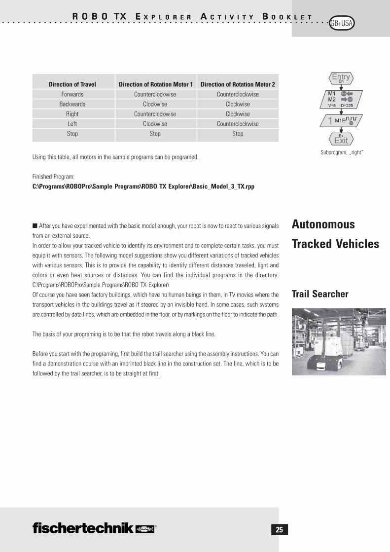
Subprogram, „right“Using this table, all motors in the sample programs can be programed.
Finished Program:C:\Programs\ROBOPro\Sample Programs\ROBO TX Explorer\Basic_Model_3_TX.rpp
■ After you have experimented with the basic model enough, your robot is now to react to various signalsfrom an external source.In order to allow your tracked vehicle to identify its environment and to complete certain tasks, you mustequip it with sensors. The following model suggestions show you different variations of tracked vehicleswith various sensors. This is to provide the capability to identify different distances traveled, light andcolors or even heat sources or distances. You can find the individual programs in the directory:C:\Programs\ROBOPro\Sample Programs\ROBO TX Explorer\Of course you have seen factory buildings, which have no human beings in them, in TV movies where thetransport vehicles in the buildings travel as if steered by an invisible hand. In some cases, such systemsare controlled by data lines, which are embedded in the floor, or by markings on the floor to indicate the path.
The basis of your programing is to be that the robot travels along a black line.
Before you start with the programing, first build the trail searcher using the assembly instructions. You canfind a demonstration course with an imprinted black line in the construction set. The line, which is to befollowed by the trail searcher, is to be straight at first.
Direction of Travel Direction of Rotation Motor 1 Direction of Rotation Motor 2Forwards Counterclockwise Counterclockwise
Backwards Clockwise ClockwiseRight Counterclockwise ClockwiseLeft Clockwise CounterclockwiseStop Stop Stop

○ ○ ○ ○ ○ ○ ○ ○ ○ ○ ○ ○ ○ ○ ○ ○ ○ ○ ○ ○ ○ ○ ○ ○ ○ ○ ○ ○ ○ ○ ○ ○ ○ ○ ○ ○ ○ ○ ○ ○ ○ ○ ○ ○ ○ ○ ○ ○ ○ ○ ○ ○ ○ ○ ○ ○ ○ ○ ○ ○ ○ ○ ○
R O B OR O B OR O B OR O B OR O B O TX TX TX TX TX EEEEE X P L O R EX P L O R EX P L O R EX P L O R EX P L O R E RRRRR AAAAA C T I V I T YC T I V I T YC T I V I T YC T I V I T YC T I V I T Y B B B B B O O K L E TO O K L E TO O K L E TO O K L E TO O K L E T
26
■ ■ ■ ■ ■ Now, how is the model to function?
The robot is to find a black line on a white background and then follow this line. To make this possible, youhave the IR trail sensor installed in your model. The module transmits a light in the infrared range to thepavement substrate. Depending on the substrate, this is reflected and measured by phototransistors. Foryour programing, this means: A bright and/or white substrate reflects the light and you receive the value1. With a black substrate, the light is not reflected and you receive the value 0. If both transistors have thevalue 0, then your robot has found the road (the black line) and must now follow this road.
Task 1 – ROBO Pro Level 2Your tracked vehicle is to be placed on a straight black trail and then travel along this.If it loses the trail or it ends, it is to stop and honk three times.
A Few Little TipsUse the interface test to check the trail identification by the sensor. Don’t forget to set the inputs to„Digital 10 V (Trail sensor).“ If the black-white identification does not function properly, theninterfering light sources such as the sun could be the cause. If necessary, the sensor must bepositioned somewhat closer to the trail or be shielded with a building board.
Finished Program: Trail_searcher_1_TX.rpp
■ Of course, you will not be satisfied with your first solution because your robot can certainly travel ashort stretch along the line. However, because it cannot yet readjust, it leaves the marking and stops andsends you a signal indicating this.
Task 2 – ROBO Pro Level 2Expand your main program in the interrogation branches of the trail sensor so thatthe robot recognizes when it is not traveling exactly on the trail. Then, it is tocorrect its direction of travel accordingly. You can find a tip in the left programsection.
Now it looks better already. Your robot remains precisely on the prescribed trail. In an industrial building,other robots would now remove the load, which was transported, at the end of the trail or would give therobot a new load. This load could then be transported back to the starting point of the trip.
Finished Program: Trail_searcher_2_TX.rpp
Branch
Motor outputBuzzer
○ ○ ○ ○ ○ ○ ○ ○ ○ ○ ○ ○ ○ ○ ○ ○ ○ ○ ○ ○ ○ ○ ○ ○ ○ ○ ○ ○ ○ ○ ○ ○ ○ ○ ○ ○ ○ ○ ○ ○ ○ ○ ○ ○ ○ ○ ○ ○ ○ ○ ○ ○ ○ ○ ○ ○ ○ ○ ○ ○ ○ ○ ○
R O B OR O B OR O B OR O B OR O B O TX TX TX TX TX EEEEE X P L O R EX P L O R EX P L O R EX P L O R EX P L O R E RRRRR AAAAA C T I V I T YC T I V I T YC T I V I T YC T I V I T YC T I V I T Y B B B B B O O K L E TO O K L E TO O K L E TO O K L E TO O K L E T
27
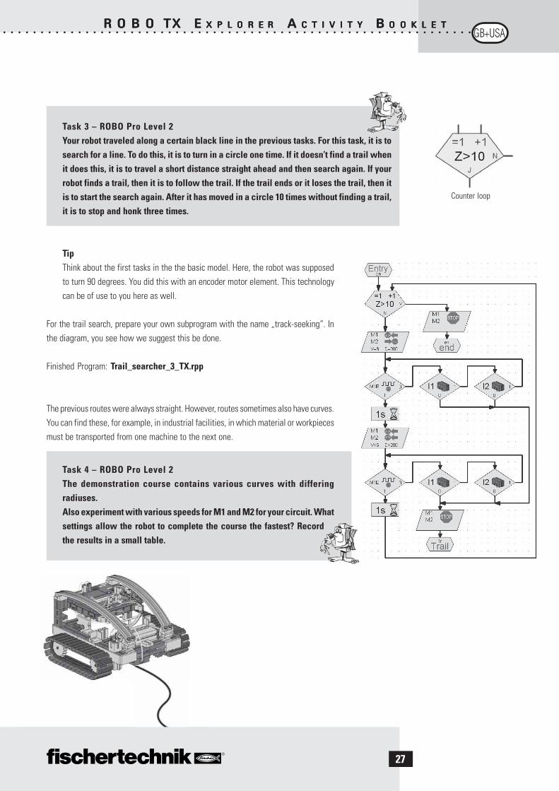
Task 3 – ROBO Pro Level 2Your robot traveled along a certain black line in the previous tasks. For this task, it is tosearch for a line. To do this, it is to turn in a circle one time. If it doesn’t find a trail whenit does this, it is to travel a short distance straight ahead and then search again. If yourrobot finds a trail, then it is to follow the trail. If the trail ends or it loses the trail, then itis to start the search again. After it has moved in a circle 10 times without finding a trail,it is to stop and honk three times.
TipThink about the first tasks in the the basic model. Here, the robot was supposedto turn 90 degrees. You did this with an encoder motor element. This technologycan be of use to you here as well.
For the trail search, prepare your own subprogram with the name „track-seeking“. Inthe diagram, you see how we suggest this be done.
Finished Program: Trail_searcher_3_TX.rpp
The previous routes were always straight. However, routes sometimes also have curves.You can find these, for example, in industrial facilities, in which material or workpiecesmust be transported from one machine to the next one.
Task 4 – ROBO Pro Level 2The demonstration course contains various curves with differingradiuses.Also experiment with various speeds for M1 and M2 for your circuit. Whatsettings allow the robot to complete the course the fastest? Recordthe results in a small table.
Counter loop

○ ○ ○ ○ ○ ○ ○ ○ ○ ○ ○ ○ ○ ○ ○ ○ ○ ○ ○ ○ ○ ○ ○ ○ ○ ○ ○ ○ ○ ○ ○ ○ ○ ○ ○ ○ ○ ○ ○ ○ ○ ○ ○ ○ ○ ○ ○ ○ ○ ○ ○ ○ ○ ○ ○ ○ ○ ○ ○ ○ ○ ○ ○
R O B OR O B OR O B OR O B OR O B O TX TX TX TX TX EEEEE X P L O R EX P L O R EX P L O R EX P L O R EX P L O R E RRRRR AAAAA C T I V I T YC T I V I T YC T I V I T YC T I V I T YC T I V I T Y B B B B B O O K L E TO O K L E TO O K L E TO O K L E TO O K L E T
28
Tunnel Robot,
Distance and
Temperature
Sensor
■ The sensor for distance measurement and the NTC resistor offer you additional possibilities to expandyour model to a professional robot.
Measuring distances and temperatures and possibly initiatingrescue measures. What do you think, where could robots withsuch capabilities be used? Of course, you can think of variousareas, where they could be used. We want to examine the area offire protection and fire fighting in auto and train tunnels.
The task for such a robot is to cautiously approach the source ofthe fire, measure temperatures in the tunnel and to report data to a control center. In most cases, therobots are equipped with mobile extinguishing equipment, which can be used depending on the conditions.
Now here as well conscientiously build the model, „tunnel robot,“ according to the assembly instructions.
Task 1- ROBO Pro Level 2Similar to the trail searcher, which travels along a line, your robot is to travel acertain route along a wall at a certain distance of about 20 centimeters.
Finished Program: Tunnel_1_TX.rpp
■ Let’s examine a fire extinguisher robot once again for the next task. In order that it can travel along thewall like your robot, it uses distance sensors. However, in order to identify the source of the fire, it employsheat sensors. This heat sensor is the NTC resistor for your model. The physical characteristic of thiscomponent is that the resistance value decreases when the temperature increases. You can try out thischange again with the interface test. Connect the NTC resistor to the connection I6. Place a heat sourcenear the NTC and observe the numerical value of the input. Don’t forget to set the input to „Analog 5 kOhm(NTC, . . . ).“The resistance value of the temperature probe is displayed at the analog input, not the temperature itself. Inorder to convert this value into a temperature, you can use the subprogram „NTC->T“ (see Tunnel_2_TX.rpp).
Task 2 – ROBO Pro Level 2Expand the program, which allows the robot to travel along the tunnel wall. In addition,measure the current temperature. If this increases to a certain value then your robot isto stop and transmit a warning signal using the buzzer. At the same time as the buzzer,the red indicator light is to blink.Following this simulated extinguishing action, your robot is to turn and return tothe starting point.
Finished Program: Tunnel_2_TX.rpp

○ ○ ○ ○ ○ ○ ○ ○ ○ ○ ○ ○ ○ ○ ○ ○ ○ ○ ○ ○ ○ ○ ○ ○ ○ ○ ○ ○ ○ ○ ○ ○ ○ ○ ○ ○ ○ ○ ○ ○ ○ ○ ○ ○ ○ ○ ○ ○ ○ ○ ○ ○ ○ ○ ○ ○ ○ ○ ○ ○ ○ ○ ○
R O B OR O B OR O B OR O B OR O B O TX TX TX TX TX EEEEE X P L O R EX P L O R EX P L O R EX P L O R EX P L O R E RRRRR AAAAA C T I V I T YC T I V I T YC T I V I T YC T I V I T YC T I V I T Y B B B B B O O K L E TO O K L E TO O K L E TO O K L E TO O K L E T
29
TipSince your robot only has one distance sensor, it needs a second wall, along which it can travel, toreturn to the starting point.
If you have another motor and a propeller in your fischertechnik collection, you can also integrate theextinguishing of the fire into your program.
■ You will get to know the color sensor as an additional sensor. The picture on the side gives you anexample for industrial use. As you can see, colored cans, which were placed in the wrong row, are beingsorted out.
The light, which is reflected from the material being examined, is received, digitalized and processedusing a computer and software. The task of the sensor is to identify the various colors and to transmit themeasurement data to the ROBO TX Controller.
The color sensor is installed in the color detector model. This is connected with the black wire to I4, thered wire to plus (+) and the green wire to the ground ( ). For the first test programs, you are to use thecolored surfaces imprinted on the course.
Task 1 – ROBO Pro Level 2First, check the values, which the interface puts out for the various colors in the interfacetest. Use black and white in addition to the three colors prescribed.
Make a small table and enter the values, which you have measured. Also observe thechanges when the distance to the colored surface or the ambient light changes.
Task 2 – ROBO Pro Level 2Write a small program, with which the sensor can identify the green colored area. If themeasured value is within the prescribed range of values, the buzzer is to be activatedfor one second. Following this, the program jumps to start.
Finished Program: Color_detector_2_TX.rpp
TipFor the next task, you need the three indicator lights with different colored luminous caps, whichare already installed in the model.
Color Detector
Color Value
White
Black
Blue
Red
Green

○ ○ ○ ○ ○ ○ ○ ○ ○ ○ ○ ○ ○ ○ ○ ○ ○ ○ ○ ○ ○ ○ ○ ○ ○ ○ ○ ○ ○ ○ ○ ○ ○ ○ ○ ○ ○ ○ ○ ○ ○ ○ ○ ○ ○ ○ ○ ○ ○ ○ ○ ○ ○ ○ ○ ○ ○ ○ ○ ○ ○ ○ ○
R O B OR O B OR O B OR O B OR O B O TX TX TX TX TX EEEEE X P L O R EX P L O R EX P L O R EX P L O R EX P L O R E RRRRR AAAAA C T I V I T YC T I V I T YC T I V I T YC T I V I T YC T I V I T Y B B B B B O O K L E TO O K L E TO O K L E TO O K L E TO O K L E T
30
Explorer
Model
Task 3 – ROBO Pro Level 3Write a program, which allows your robot to travel straight ahead for a certain distance.There are three colored areas on this route. If the sensor detects a color, the robot is tostop for three seconds. During this time, it turns on the indicator lights with thecorresponding color and emits an acoustic signal with the buzzer. Following this, ittravels to the next area and repeats its work. Following this, it travels to the last area,reports the result and stops there.
Finished Program: Color_detector_3_TX.rpp
■ The „Explorer“ model contains all actuators andsensors, which are needed for an autonomous roboticvehicle.Now, you have no limits for the solution of simple anddifficult tasks. In the preceding construction stages,you have only used one sensor in most cases to becomefamiliar with the possible areas of employment.
Task 1 – ROBO Pro Level 2Program your robot so that it moves towards an existing obstacle on its trip. At a distanceof about 60 centimeters, it is to reduce its speed. At a distance of 40 centimeters, it is tostop. If the obstacle moves closer to your robot, the robot is to move backwards slowlyat a distance of 20 centimeters and at 10 centimeters, it is to move backwards fast.
Finished Program: Explorer_1_TX.rpp
Task 2 – ROBO Pro Level 2Now, your robot is going on its exploration trip. Prepare a program for the use of twosensors: trail sensor and distance sensor. First, the robot is to follow the black line onthe demonstration course. Place an obstacle on the route. The robot is to stop about 10centimeters in front of the obstacle and travel one centimeter backwards. Followingthis, it is to turn around and follow the trail in the other direction.
Finished Program: Explorer_2_TX.rpp
○ ○ ○ ○ ○ ○ ○ ○ ○ ○ ○ ○ ○ ○ ○ ○ ○ ○ ○ ○ ○ ○ ○ ○ ○ ○ ○ ○ ○ ○ ○ ○ ○ ○ ○ ○ ○ ○ ○ ○ ○ ○ ○ ○ ○ ○ ○ ○ ○ ○ ○ ○ ○ ○ ○ ○ ○ ○ ○ ○ ○ ○ ○
R O B OR O B OR O B OR O B OR O B O TX TX TX TX TX EEEEE X P L O R EX P L O R EX P L O R EX P L O R EX P L O R E RRRRR AAAAA C T I V I T YC T I V I T YC T I V I T YC T I V I T YC T I V I T Y B B B B B O O K L E TO O K L E TO O K L E TO O K L E TO O K L E T
31
Task 3 – ROBO Pro Level 2The program from task 2 is to be expanded with three sensors: the color detector, thetemperature sensor and the photoresistor for the measurement of brightness.
There are various colored areas along the trail. The robot reports these with variousacoustic signals. If the ambient temperature becomes too high during the trip, the redindicator light is to blink. As soon as the room becomes dark, your robot turns on its twoheadlights. If it gets bright again, the headlights are turned off.
Finished Program: Explorer_3_TX.rpp
■ Our Explorer can also be programed as a remote controlled robot to explore unknown worlds. To dothis, the ROBO TX Controller is connected with the computer using the Bluetooth radio interface.
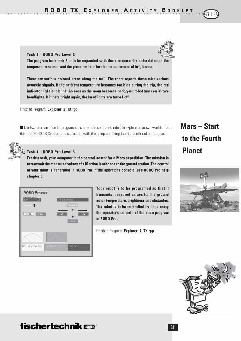
Task 4 – ROBO Pro Level 3For this task, your computer is the control center for a Mars expedition. The mission isto transmit the measured values of a Martian landscape to the ground station. The controlof your robot is generated in ROBO Pro in the operator’s console (see ROBO Pro helpchapter 9).
Your robot is to be programed so that ittransmits measured values for the groundcolor, temperature, brightness and obstacles.The robot is to be controlled by hand usingthe operator’s console of the main programin ROBO Pro.
Finished Program: Explorer_4_TX.rpp
Mars – Start
to the Fourth
Planet

○ ○ ○ ○ ○ ○ ○ ○ ○ ○ ○ ○ ○ ○ ○ ○ ○ ○ ○ ○ ○ ○ ○ ○ ○ ○ ○ ○ ○ ○ ○ ○ ○ ○ ○ ○ ○ ○ ○ ○ ○ ○ ○ ○ ○ ○ ○ ○ ○ ○ ○ ○ ○ ○ ○ ○ ○ ○ ○ ○ ○ ○ ○
R O B OR O B OR O B OR O B OR O B O TX TX TX TX TX EEEEE X P L O R EX P L O R EX P L O R EX P L O R EX P L O R E RRRRR AAAAA C T I V I T YC T I V I T YC T I V I T YC T I V I T YC T I V I T Y B B B B B O O K L E TO O K L E TO O K L E TO O K L E TO O K L E T
32
RoboCupJunior
Rescue Robot
Important Tips
Now, you have performed all tasks, become familiar with the construction of a robot and the programingtechnology, so now you could harvest the fruits of your labor and participate in the Rescue League of theRoboCupJunior with the „rescue robot“ model.
■ RoboCupJunior is a worldwide, project oriented education initiative, which promotes regional, nationaland international robot events for young people. The goal is to introduce children and young people torobots and their application.
Using the tasks, which you can obtain from the Internet at
http://rcj.robocup.org
it will certainly be easy for you to program your rescue robot for thiscompetition.
The picture on the left shows you a course, which your robot must traver-se. On this route, it must complete various tasks, for example, travelingalong a line, searching for figures of various colors on the floor or travelthrough a door and so forth. Wouldn’t that be something for you?
■ The fun with the subject of robotics can be lost very fast if the robot doesn’t function like you want it tofunction.
Often, simple means can be used to identify and eliminate errors.
CablesHere, you must proceed precisely. First, the cables are cut to the prescribed length and then the ends areto be stripped of insulation and connected firmly with the plugs. Check for proper functioning using aluminous stone (38216), with ball plug-in light (37869) and the rechargeable battery pack.
Power SupplyOften, a rechargeable battery, which is almost totally discharged, is the cause of erroneous behavior byyour ROBO TX Explorer. If the voltage drops below five volts, the ROBO TX Controller shuts off automatically.Improper functioning can also occur even if the rechargeable battery is not so low. But then the rechargeablebattery must still be charged.
ProgramingWhen all mechanical problems have been solved and the robot is still not quite right, this is often due toerrors in programing. Here, ROBO Pro offers you the online mode, which allows you to follow the programflow on the monitor. In most cases here, you can find the small program errors, which have crept in.
