actuator control for a hybrid suspension systemmediatum.ub.tum.de/doc/1093263/1093263.pdf ·...
TRANSCRIPT
Technical Reports on Automatic ControlVol. TRAC-6, December 1, 2011
Available online at: www.rt.mw.tum.de
Actuator Control for a Hybrid Suspension System
Guido Koch∗, Enrico Pellegrini, Sebastian Spirk, Nils Pletschen and Boris Lohmann
Institute of Automatic Control, Technische Universitat Munchen
Boltzmannstr. 15, D-85748 Garching, Germany
Abstract
This report presents actuator control concepts for a new structure of a mechatronic suspen-sion system entitled hybrid suspension, which includes a combination of a semi-active damperand a low bandwidth actuator integrated in series to the primary spring and can potentiallyachieve a performance similar to a fully active suspension system. An overview on the designand constructive realization of the hybrid suspension based on actuator components fromproduction vehicles is given. Models and control approaches for the two integrated actuatorsare derived and the integration of the hybrid suspension in a quarter-car test rig is presented.
Keywords: Vehicle suspension; Active and semi-active suspensions; Quarter-car test rig;Tracking control; Hydraulic systems.
1 Introduction
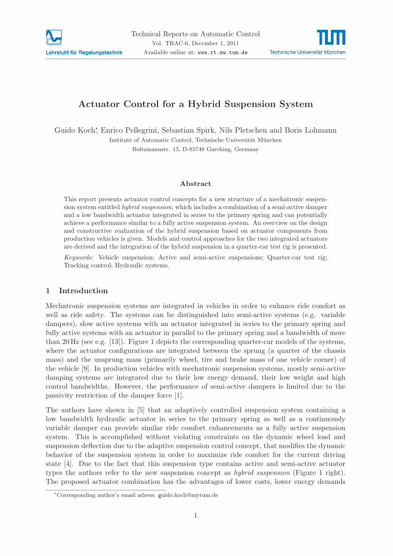
Mechatronic suspension systems are integrated in vehicles in order to enhance ride comfort aswell as ride safety. The systems can be distinguished into semi-active systems (e.g. variabledampers), slow active systems with an actuator integrated in series to the primary spring andfully active systems with an actuator in parallel to the primary spring and a bandwidth of morethan 20Hz (see e.g. [13]). Figure 1 depicts the corresponding quarter-car models of the systems,where the actuator configurations are integrated between the sprung (a quarter of the chassismass) and the unsprung mass (primarily wheel, tire and brake mass of one vehicle corner) ofthe vehicle [9]. In production vehicles with mechatronic suspension systems, mostly semi-activedamping systems are integrated due to their low energy demand, their low weight and highcontrol bandwidths. However, the performance of semi-active dampers is limited due to thepassivity restriction of the damper force [1].
The authors have shown in [5] that an adaptively controlled suspension system containing alow bandwidth hydraulic actuator in series to the primary spring as well as a continuouslyvariable damper can provide similar ride comfort enhancements as a fully active suspensionsystem. This is accomplished without violating constraints on the dynamic wheel load andsuspension deflection due to the adaptive suspension control concept, that modifies the dynamicbehavior of the suspension system in order to maximize ride comfort for the current drivingstate [4]. Due to the fact that this suspension type contains active and semi-active actuatortypes the authors refer to the new suspension concept as hybrid suspension (Figure 1 right).The proposed actuator combination has the advantages of lower costs, lower energy demands
∗Corresponding author’s email adress: [email protected]
1
TUM Tech. Rep. Auto. Cont. Vol. TRAC-6 2
compared to a high bandwidth active system and the fact that the actuator types are alreadyavailable in production vehicles. In [6] and [4] a suitable adaptive control approach for thehybrid suspension has been presented and the advantages of the hybrid suspension have beenexperimentally validated on a quarter-car test rig designed by the authors.
cc dc
mc
cw
mw
xw
xg
xc
dw
xc
cc d (t)c
mc
cw
mw
xw
xg
dw
xc
F(t)dccc
mc
cw
mw
xw
xg
dw
xc
d (t)c
cc
mc
xact
cw
mw
xw
xg
dw
Figure 1: Quarter-vehicle models of a passive, semi-active, fully active and the hybrid suspensionsystem.
This report presents the hybrid suspension system in more detail with an emphasis being givenon the description of the actuator modeling and control concepts. Measurement data visualizingthe model quality and the actuator performance is presented. Moreover, the quarter-car test rigdesigned to validate the performance of the hybrid suspension system is presented with a focuson the integration of the suspension strut.
The report is organized as follows: The design of the hybrid suspension strut based on therequirements of the system is described in Section 2. In Section 3 the modeling and a controlapproach for the actuators are presented and Section 4 describes the quarter-car test rig structurethe hybrid suspension strut is integrated in. A conclusion and an outlook on future work is givenin Section 5.
2 Design of the hybrid suspension
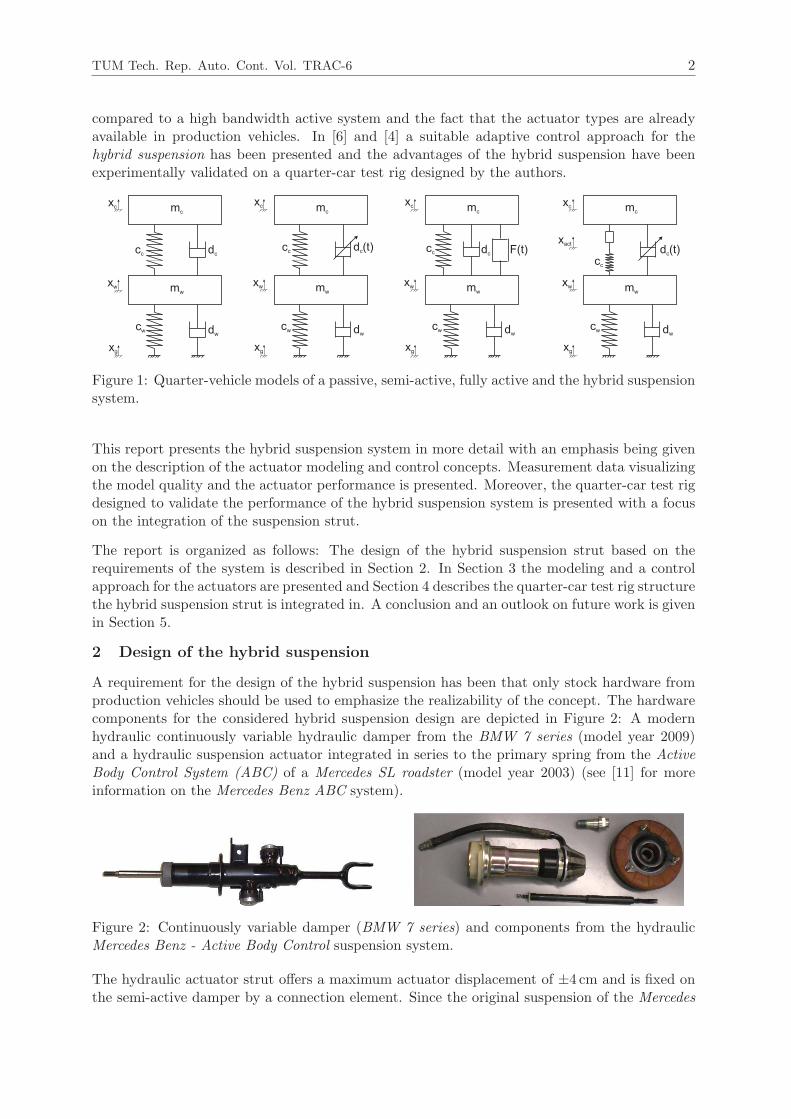
A requirement for the design of the hybrid suspension has been that only stock hardware fromproduction vehicles should be used to emphasize the realizability of the concept. The hardwarecomponents for the considered hybrid suspension design are depicted in Figure 2: A modernhydraulic continuously variable hydraulic damper from the BMW 7 series (model year 2009)and a hydraulic suspension actuator integrated in series to the primary spring from the ActiveBody Control System (ABC) of a Mercedes SL roadster (model year 2003) (see [11] for moreinformation on the Mercedes Benz ABC system).
Figure 2: Continuously variable damper (BMW 7 series) and components from the hydraulicMercedes Benz - Active Body Control suspension system.
The hydraulic actuator strut offers a maximum actuator displacement of ±4 cm and is fixed onthe semi-active damper by a connection element. Since the original suspension of the Mercedes

TUM Tech. Rep. Auto. Cont. Vol. TRAC-6 3
SL roadster has a lower transmission ratio (ratio of the relative velocity at the suspension ele-ments and the relative velocity of chassis and wheel mass [8]) than the BMW 7 series suspension,the spring of the Mercedes Benz is not suitable for the double wishbone suspension configurationof the BMW, serving as framework for the hybrid suspension. Therefore, a new spring is inte-grated, which exhibits the same stiffness characteristic as the original BMW spring but preservesthe kinematic relations despite the superimposed deflections of the hydraulic actuator. Figure3 shows the CAD based design and the realization of the hybrid suspension strut.
Figure 3: Concept (upper) und realization (lower) of the hybrid suspension.
2.1 Low bandwidth actuator
Figure 4: Valve block with pressure accumulators and pressure sensor (upper).
For the hydraulic power supply of the actuator, the same pump, which supplies the hydrauliccylinder emulating the road excitation at the test rig, is used. To control the hydraulic actu-ator, an external valve block (Figure 4 upper) is employed. To ensure comparability with thespecifications of the stock components of the Active Body Control system, the bandwidth of thecontrol valve is limited as described in Section 3.2. The valve block has integrated pressureaccumulators for the supply and the return lines as well as a pressure sensor in the supply lineof the cylinder.
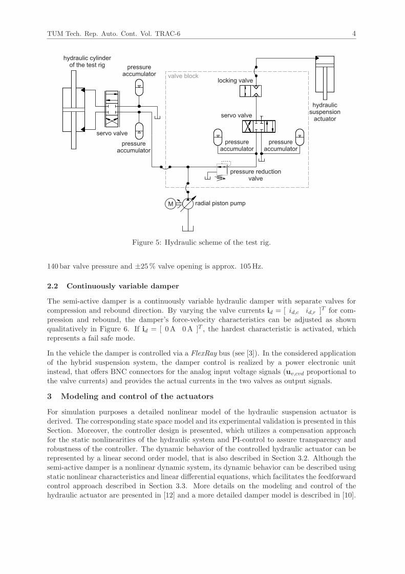
The hydraulic plan of the test rig is depicted in Figure 5: The supplying oil flow of the hydraulicpump is split into two parts for the hydraulic ram of the test rig and the hydraulic suspensionactuator. The supply pressure’s nominal value for the valve block is pV = 200 bar, which canbe adjusted using a pressure reduction valve (see also [2]). A locking valve can be used todisconnect the actuator from the servo valve. The −3 dB-cutoff frequency of the servo valve at
TUM Tech. Rep. Auto. Cont. Vol. TRAC-6 4
servo valve
locking valve
pressure reductionvalve
hydraulicsuspension
actuator
hydraulic cylinderof the test rig
radial piston pump
pressureaccumulator
servo valve
pressureaccumulator
M
pressureaccumulator
pressureaccumulator valve block
Figure 5: Hydraulic scheme of the test rig.
140 bar valve pressure and ±25% valve opening is approx. 105Hz.
2.2 Continuously variable damper
The semi-active damper is a continuously variable hydraulic damper with separate valves forcompression and rebound direction. By varying the valve currents id = [ id,c id,r ]T for com-pression and rebound, the damper’s force-velocity characteristics can be adjusted as shownqualitatively in Figure 6. If id = [ 0A 0A ]T , the hardest characteristic is activated, whichrepresents a fail safe mode.
In the vehicle the damper is controlled via a FlexRay bus (see [3]). In the considered applicationof the hybrid suspension system, the damper control is realized by a power electronic unitinstead, that offers BNC connectors for the analog input voltage signals (uv,cvd proportional tothe valve currents) and provides the actual currents in the two valves as output signals.
3 Modeling and control of the actuators
For simulation purposes a detailed nonlinear model of the hydraulic suspension actuator isderived. The corresponding state space model and its experimental validation is presented in thisSection. Moreover, the controller design is presented, which utilizes a compensation approachfor the static nonlinearities of the hydraulic system and PI-control to assure transparency androbustness of the controller. The dynamic behavior of the controlled hydraulic actuator can berepresented by a linear second order model, that is also described in Section 3.2. Although thesemi-active damper is a nonlinear dynamic system, its dynamic behavior can be described usingstatic nonlinear characteristics and linear differential equations, which facilitates the feedforwardcontrol approach described in Section 3.3. More details on the modeling and control of thehydraulic actuator are presented in [12] and a more detailed damper model is described in [10].

TUM Tech. Rep. Auto. Cont. Vol. TRAC-6 5
0
0
Velocity xc − xw
Force
Fd
Figure 6: Qualitative characteristics of the continuously variable semi-active damper.
3.1 Hydraulic actuator model
A schematic of the main components of the hydraulic actuator system (valve and piston), thatis integrated into the hybrid suspension (see Figure 1), is depicted in Figure 7.
xc
cc
mc
xr
xw
u(t)
pVpT
q
A, pc
Figure 7: Schematic of the hydraulic low bandwidth actuator system.
For the modeling the hydraulic actuator system is considered in more detail and is thereforestructured into 3 parts (see Figure 8):
• The valve: Modeled by an electrical part (relating the input voltage to the position of thevalve spool) and a hydraulic part (describing the relation of the pressure at the valve andthe corresponding flow rate).
• The tubes: Taking into account the hydraulic capacity and inductance, the pressures andoil flows between the valve and the cylinder are modeled.
• The hydraulic cylinder: The cylinder pressure is related to its movement, which is modeledby a nonlinear third order state space model.
TUM Tech. Rep. Auto. Cont. Vol. TRAC-6 6
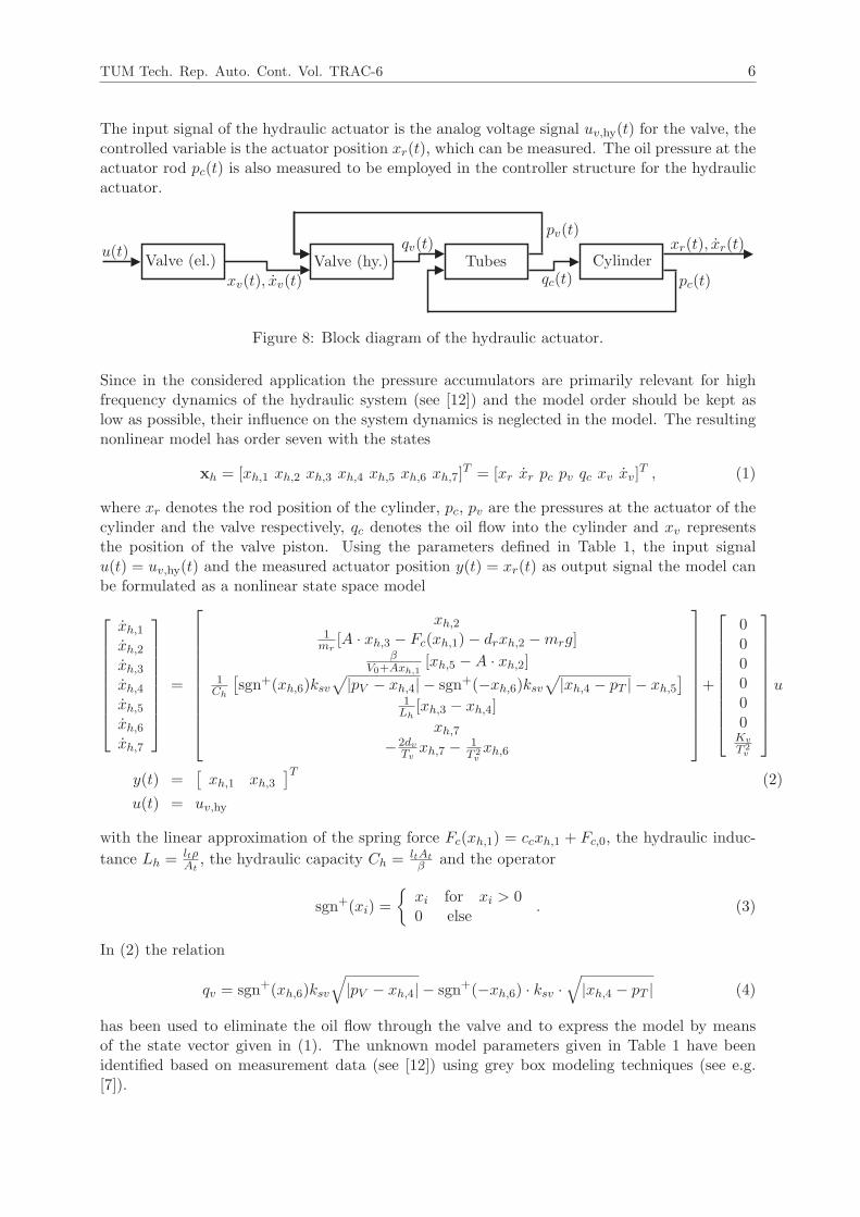
The input signal of the hydraulic actuator is the analog voltage signal uv,hy(t) for the valve, thecontrolled variable is the actuator position xr(t), which can be measured. The oil pressure at theactuator rod pc(t) is also measured to be employed in the controller structure for the hydraulicactuator.
Valve (el.) Valve (hy.) Tubes Cylinderu(t)
xv(t), xv(t)
qv(t)pv(t)
qc(t) pc(t)
xr(t), xr(t)
Figure 8: Block diagram of the hydraulic actuator.
Since in the considered application the pressure accumulators are primarily relevant for highfrequency dynamics of the hydraulic system (see [12]) and the model order should be kept aslow as possible, their influence on the system dynamics is neglected in the model. The resultingnonlinear model has order seven with the states
xh = [xh,1 xh,2 xh,3 xh,4 xh,5 xh,6 xh,7]T = [xr xr pc pv qc xv xv]
T , (1)
where xr denotes the rod position of the cylinder, pc, pv are the pressures at the actuator of thecylinder and the valve respectively, qc denotes the oil flow into the cylinder and xv representsthe position of the valve piston. Using the parameters defined in Table 1, the input signalu(t) = uv,hy(t) and the measured actuator position y(t) = xr(t) as output signal the model canbe formulated as a nonlinear state space model
xh,1xh,2xh,3xh,4xh,5xh,6xh,7
=
xh,21mr
[A · xh,3 − Fc(xh,1)− drxh,2 −mrg]β
V0+Axh,1[xh,5 −A · xh,2]
1Ch
[
sgn+(xh,6)ksv√
|pV − xh,4| − sgn+(−xh,6)ksv√
|xh,4 − pT | − xh,5]
1Lh
[xh,3 − xh,4]
xh,7−2dv
Tvxh,7 −
1T 2vxh,6
+
000000Kv
T 2v
u
y(t) =[
xh,1 xh,3]T
(2)
u(t) = uv,hy
with the linear approximation of the spring force Fc(xh,1) = ccxh,1 + Fc,0, the hydraulic induc-
tance Lh = ltρAt
, the hydraulic capacity Ch = ltAt
βand the operator
sgn+(xi) =
{
xi for xi > 00 else
. (3)
In (2) the relation
qv = sgn+(xh,6)ksv
√
|pV − xh,4| − sgn+(−xh,6) · ksv ·√
|xh,4 − pT | (4)
has been used to eliminate the oil flow through the valve and to express the model by meansof the state vector given in (1). The unknown model parameters given in Table 1 have beenidentified based on measurement data (see [12]) using grey box modeling techniques (see e.g.[7]).
TUM Tech. Rep. Auto. Cont. Vol. TRAC-6 7
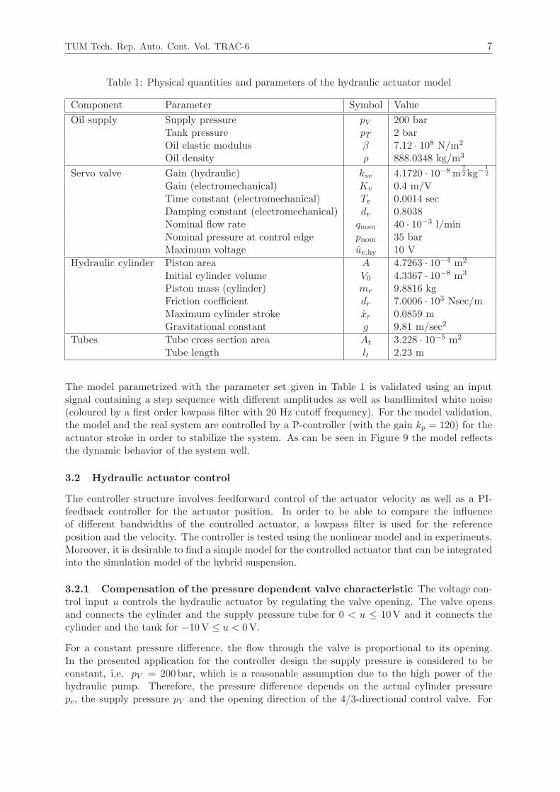
Table 1: Physical quantities and parameters of the hydraulic actuator model
Component Parameter Symbol Value
Oil supply Supply pressure pV 200 barTank pressure pT 2 barOil elastic modulus β 7.12 · 108 N/m2
Oil density ρ 888.0348 kg/m3
Servo valve Gain (hydraulic) ksv 4.1720 · 10−8m7
2kg−1
2
Gain (electromechanical) Kv 0.4 m/VTime constant (electromechanical) Tv 0.0014 secDamping constant (electromechanical) dv 0.8038Nominal flow rate qnom 40 · 10−3 l/minNominal pressure at control edge pnom 35 barMaximum voltage uv,hy 10 V
Hydraulic cylinder Piston area A 4.7263 · 10−4 m2
Initial cylinder volume V0 4.3367 · 10−8 m3
Piston mass (cylinder) mr 9.8816 kgFriction coefficient dr 7.0006 · 103 Nsec/mMaximum cylinder stroke xr 0.0859 mGravitational constant g 9.81 m/sec2
Tubes Tube cross section area At 3.228 · 10−5 m2
Tube length lt 2.23 m
The model parametrized with the parameter set given in Table 1 is validated using an inputsignal containing a step sequence with different amplitudes as well as bandlimited white noise(coloured by a first order lowpass filter with 20 Hz cutoff frequency). For the model validation,the model and the real system are controlled by a P-controller (with the gain kp = 120) for theactuator stroke in order to stabilize the system. As can be seen in Figure 9 the model reflectsthe dynamic behavior of the system well.
3.2 Hydraulic actuator control
The controller structure involves feedforward control of the actuator velocity as well as a PI-feedback controller for the actuator position. In order to be able to compare the influenceof different bandwidths of the controlled actuator, a lowpass filter is used for the referenceposition and the velocity. The controller is tested using the nonlinear model and in experiments.Moreover, it is desirable to find a simple model for the controlled actuator that can be integratedinto the simulation model of the hybrid suspension.
3.2.1 Compensation of the pressure dependent valve characteristic The voltage con-trol input u controls the hydraulic actuator by regulating the valve opening. The valve opensand connects the cylinder and the supply pressure tube for 0 < u ≤ 10V and it connects thecylinder and the tank for −10V ≤ u < 0V.
For a constant pressure difference, the flow through the valve is proportional to its opening.In the presented application for the controller design the supply pressure is considered to beconstant, i.e. pV = 200 bar, which is a reasonable assumption due to the high power of thehydraulic pump. Therefore, the pressure difference depends on the actual cylinder pressurepc, the supply pressure pV and the opening direction of the 4/3-directional control valve. For

TUM Tech. Rep. Auto. Cont. Vol. TRAC-6 8
3 4 5 6 7 8 9 10 11 12 13 140
20
40
60
80Ref.stroke
[mm]
3 4 5 6 7 8 9 10 11 12 13 140
20
40
60
3 4 5 6 7 8 9 10 11 12 13 14−50
0
50
100
150
SimulationMeasurement
SimulationMeasurement
Strokexr[m
m]
Time [sec]Cylinder
pressure
pc[bar]
Figure 9: Validation of the hydraulic actuator model (measurement and simulation).
positive oil flow into the cylinder, the relevant pressure difference is determined by the hydraulicsupply pressure pV and the pressure in the cylinder pc. For negative oil flow from the cylinder tothe tank, the pressure drop only depends on pc as the tank pressure is neglegible. The cylinderpressure itself is dynamically coupled to the spring force (in the equilibrium the cylinder pressureequals the spring force divided by the cylinder cross section area) and thus the movements of theactuator and the vehicle suspension. The occuring pressure variations due to the spring deflectionand the switching of the valve cause a nonlinear behavior of the valve dynamics: The relationbetween the valve opening and flow rate is disturbed by the cylinder pressure fluctuations. Tocompensate this disturbance that influences the valve characteristic, the cylinder pressure pcis measured and its effects are eliminated by a nonlinear compensation approach scaling thedesired control output u∗ by a factor depending on the actual value of pc.
In the equilibrium of the suspension, the valve is closed and the spring induces the pressurepc,0 = 67bar in the hydraulic actuator. Thereby, in the equilibrium a reference pressure
p0 = pV − pc,0 = 200 bar− 67 bar = 133 bar (5)
is defined, that characterizes the available pressure for generating a positive actuator displace-
TUM Tech. Rep. Auto. Cont. Vol. TRAC-6 9
ment (spring compression) from the equilibrium by supplying oil to the actuator by the pump.If the spring deflects, pc changes, which in turn alters the pressure difference on the valve andthereby affects the valve’s flow characteristic. For the following considerations, the pressuredeviation ∆p from the equilibrium pressure p0 is considered, which depends on the cylinderpressure pc and on the sign of the valve input signal.
For positive valve input voltages u ≥ 0, the pressure difference is
∆ppos(pc) = (pV − pc)− (pV − pc,0) = pc,0 − pc . (6)
If a negative control voltage u < 0 is applied, the valve connects the actuator to the tank.Since the tank pressure is neglegible and pV is no longer applied to the actuator, the pressuredifference on the valve equals pc. In the equilibrium pc = pc,0 holds, thus the pressure difference∆pneg in the equilibrium for negative control voltages becomes
∆pneg(pc = pc,0) = pc,0 − p0 (7)
= 67 bar− 133 bar = −66 bar . (8)
These resulting pressure differences can be utilized to express the relation between the flow rateV and the valve’s input signal u as
V = (∆p
p0+ 1) · u · c , (9)
where c is a constant factor and the pressure deviation from the equilibrium point results from(6) and (8) as
∆p(pc) =
{
∆ppos = pc,0 − pc if u ≥ 0,
∆pneg = pc − p0 if u < 0. (10)
This means for negative valve opening in the equilibrium, the valve flow rate would be diminishedto approx. half the positive flow rate, i.e.
V = (∆pnegp0
+ 1) · u · c = 0.504 · u · c . (11)
To get the desired linear relation
V!= u∗ · c (12)
between the desired controller output u∗ and the flow rate, the measured cylinder pressure pc isused to calculate the scaled controller output as summarized in Figure 10, i.e.
u =u∗
(∆pp0
+ 1)with ∆p =
{
pc,0 − pc if u ≥ 0,
pc − p0 if u < 0. (13)
3.2.2 Controller structure The controller structure depicted in Figure 11 realizes the track-ing of the actuator displacement y = xr (the reference displacement is denoted as w = x∗r).Neglecting oil compressibility the actuator velocity depends directly proportional (due to theconstant piston area) on the valve flow rate, a feedforward control strategy is implemented uti-lizing the desired actuator profile velocity. To tune the feedforward gain, a ramp excitationaround the equilibrium point has been used to determine the required gains as inverse values ofthe static plant gains. Thereby, an average gain of 8.9 V
m/sec for positive velocities and 18.2 Vm/sec

TUM Tech. Rep. Auto. Cont. Vol. TRAC-6 10
Compensation
∆p
u∗ u Vu = u∗
∆p
p0+1 V =
(
∆pp0
+ 1)
uc
Figure 10: Compensation scheme for the valve nonlinearity
for negative velocities has been identified. The proportion of negative and positive gain coin-cides with the employed compensation of the valve pressure variations. Thus, for the feedforwardcontrol the value kf = 8.9 is used as it refers to the reference pressure p0.
The resulting controller structure consists of the velocity feedforward control and a PI-controller(gains kp = 650, ki = 1000) to compensate remaining errors. The feedforward gain is scaleddepending on the sign of the control deviation and the actual cylinder pressure as formulatedin (13). To avoid a direct coupling of pc on the feedback gains, the gain of the proportionalfeedback is scaled only by the static values of ∆p at the equilibrium (pc = pc,0) depending on thesign of the control voltage (see (6) and (8)). Since this control leads to a high bandwidth beyondthe desired values, lowpass filtering of the reference displacement and velocity is used to be ableto adjust the actuator bandwidth in order to study its effects on the suspension performance(wf denotes the filtered reference displacement). The default bandwidth is chosen to be 5Hz,which is the original bandwidth of the Active Body Control System.
-w
wf
wf e u
f(u∗,∆p(pc))
f(u∗,∆p(pc = pc,0))
Glp(s)
Glp(s)
ki
kf
kp
yPlant
Figure 11: Compensation scheme for the valve nonlinearity
3.2.3 Model of the closed loop system In order to reflect the behavior of the controlledactuator, a simplified model can be utilized. Due to the direct influence of the lowpass filters’cutoff frequency ωc on the bandwidth of the closed loop system, the dynamics of the controlledactuator can be described in the low frequency range of interest by a second order linear model.Lag effects of the system can be summarized by means of a time delay of Td = 3msec, which isimplemented by a first order Pade-approximation in the model. The resulting model is
xhy(t) =
[
−ωc 01Td
− 1Td
]
xhy(t) +
[
ωc
0
]
x∗r(t) , (14)
xr(t) =[
0 1]
xhy(t) (15)
with the desired actuator stroke x∗r(t), xhy(t) being the state vector of the controlled actuatorand the actuator stroke xr(t) as model output. The model has been proposed by the authors in
TUM Tech. Rep. Auto. Cont. Vol. TRAC-6 11
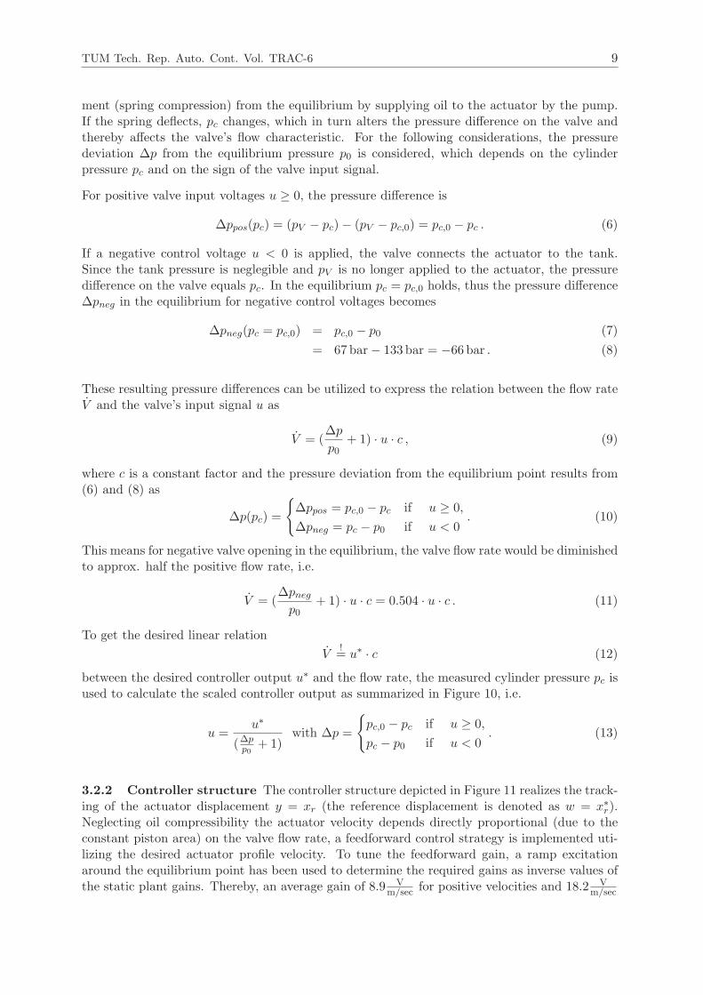
[6] and reflects the dynamics of the closed loop system well as can be seen in a comparison ofthe model output with measurement data (with a bandwidth of 5Hz) depicted in Figure 12.
0 1 2 3 4 5 6 7 8
0.04
0.045
0.05
0.055
0.06
0.065
0.07
Reference positionSimulation (2nd order actuator model) Measurement
Strokexr[m
]
Time [sec]
Figure 12: Comparison between measurement and linear second order model for an actuatorbandwidth of 5Hz
3.3 Damper model and control
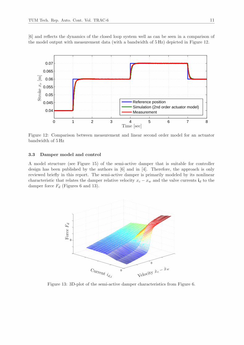
A model structure (see Figure 15) of the semi-active damper that is suitable for controllerdesign has been published by the authors in [6] and in [4]. Therefore, the approach is onlyreviewed briefly in this report. The semi-active damper is primarily modeled by its nonlinearcharacteristic that relates the damper relative velocity xc − xw and the valve currents id to thedamper force Fd (Figures 6 and 13).
0
0
0
Velocity xc −
xw
Force
Fd
Current id,i
Figure 13: 3D-plot of the semi-active damper characteristics from Figure 6.

TUM Tech. Rep. Auto. Cont. Vol. TRAC-6 12
Moreover, the dynamic behavior of the damper is described by the transfer functions
Gm(s) =1
Tmechs+ 1, (16)
Gel(s) =
[
Gel,1(s) 00 Gel,2(s)
]
with Gel,1(s) = Gel,2(s) =1
Tels+ 1(17)
with Tmech and Tel being identified mechanical and electrical time constants of the damper,respectively.
The mechanical dynamics are described by Gm(s) (input signal: static damper force Fd,s; outputsignal: actual damper force Fd). The electrical dynamics are characterized by the transfer matrixGel(s) (input signals: voltage inputs of the power electronic unit uv,cvd; output signals: valvecurrents id). The damper current signals id are available as measurement signals at the powerelectronic unit. A more detailed nonlinear physical model of the semi-active damper is presentedin [10]. The dependency of the damper’s mechanical dynamics on the velocity direction and thecurrent will be analyzed in future work in more detail. The power electronic unit is controlledby an internal PI-controller. The validation of the electrical part of the model is depicted inFigure 14, that shows a step response of the valve currents (model output vs. measured data).
0.98 0.99 1 1.01 1.02 1.03 1.04 1.05 1.06 1.070
Reference CurrentSimulationMeasurement
Current[A
]
Time [sec]
Figure 14: Damper current step response (measurement and simulation).
˙xc − ˙xw
F ∗
d id
i∗d
xc − xw
FdFd,s
Damper characteristicInverse characteristic
Gel(s) Gm(s)
Figure 15: Feedforward control and damper model (see also [6]).
For the control of the damper, a feedforward prefiltering approach using an inversion of the staticdamper characteristic is employed (see Figure 15). The desired damper force is denoted as F ∗
d ,the current damper velocity is estimated and denoted as ˙xc− ˙xw (see [4]). The resulting desireddamper currents i∗d are calculated from the inverse of the three-dimensional damper characteristicin Figure 13 and Fd,s represents the static damper force as described by the nonlinear damper

TUM Tech. Rep. Auto. Cont. Vol. TRAC-6 13
characteristics. Since the damper force is not measured directly, a force control loop can beadded based on a damper force estimation, which will be subject of future work.
4 Automotive quarter-car test rig
The hybrid suspension is integrated into a quarter-car test rig (Figure 16), that has been designedto evaluate the performance of suspension control algorithms in a realistic framework. For moredetailed information on the test rig, the suspension components as well as modeling and controlaspects the reader is referred to [4].
Figure 16: CAD-concept (left) und realization (right) of the hybrid suspension test rig.
The test rig is designed using parameters of the BMW 7 series (model year 2009), i.e. thesprung mass is mc ≈ 500 kg and the unsprung mass is mw ≈ 70 kg. Due to the added length ofthe hybrid suspension strut, an extension of the test rig frame is used for the mounting of thestrut. However, the position and orientation of the hybrid suspension strut is the same as in theBMW 7 series’ original suspension system, i.e. the kinematic relations of the original suspensionconfiguration including the deflection depending transmission factor (see [8]) are preserved. It isnoted that the length of the hybrid suspension strut could be significantly reduced if the damperdesign is adjusted for its integration into the hybrid suspension setup.
A highly dynamic hydraulic actuator supplied with a pressure of 250 bar is used to excite thetire vertically and thereby emulates the road excitation (see Figure 5). The sprung mass isguided vertically by a parallel kinematics mounting to reduce friction forces. The structure ismounted on a steel base plate resting on 16 airsprings to isolate the building from vibrations.
5 Conclusion and outlook
A realization of a hybrid suspension system has been presented. The system involves a con-tinuously variable semi-active damper and a low bandwidth actuator, which is implemented inseries to the primary spring of the suspension. The hybrid suspension can be realized using stockhardware of production vehicles. The presented models of the actuators reflect their dynamicbehavior well and the transparent control concepts are well applicable in terms of computationalcomplexity for real time application at the test rig. Future work of the authors will involve morecomplex control schemes for the semi-active damper as well as further study of high-level vehiclesuspension control concepts for the hybrid suspension system.
TUM Tech. Rep. Auto. Cont. Vol. TRAC-6 14
Acknowledgements
The authors would like to thank Thomas Huber for his great input and the realization of thesuspension as well as the test rig configuration. Furthermore, the authors would like to thankCarsten Bischoff, Dr. Marcus Jautze, Dr. Markus Nyenhuis and Karsten Roski at BMW AGfor providing suspension components and helpful hints to realize the hybrid suspension test rig.The funding support provided by the DFG (German Research Foundation) for the realization ofthe hybrid suspension test rig and for the project of Nils Pletschen at the Institute of AutomaticControl is greatly appreciated. Last but not least, the authors are grateful to all colleaguesand students, who have significantly supported the project, especially Christian Rathgeber andBastian Weigl.
References
[1] D. Fischer and R. Isermann. Mechatronic semi-active and active vehicle suspensions. Con-trol Engineering Practice, 12:1353 – 1367, 2004.
[2] Herbert Haenchen GmbH. Datasheet of hydraulic valve block, 2010.
[3] M. Jautze, A. Bogner, J. Eggendinger, G. Rekewitz, and A. Stumm. Das Ver-stelldampfersystem Dynamische Dampfer Control. ATZ extra, Sonderheft: Der neue BMW7er:100–103, 2008.
[4] G. Koch. Adaptive Control of Mechatronic Vehicle Suspension Systems. PhD thesis, Tech-nische Universitat Munchen, 2011.
[5] G. Koch, O. Fritsch, and B. Lohmann. Potential of low bandwidth active suspension controlwith continuously variable damper. Control Engineering Practice, 18:1251 – 1262, 2010.
[6] G. Koch, S. Spirk, and B. Lohmann. Reference model based adaptive control of a hybridsuspension system. Proceedings of the IFAC Symposium Advances in Automotive Control,2010.
[7] L. Ljung. System Identification - Theory for the user. Prentice Hall, USA, 1999.
[8] W. Matschinsky. Radfuhrungen der Straßenfahrzeuge - Kinematik, Elasto-Kinematik undKonstruktion. Springer, 2007.
[9] M. Mitschke and H. Wallentowitz. Dynamik der Kraftfahrzeuge. Springer, Berlin, 2004.
[10] E. Pellegrini, G. Koch, and B. Lohmann. Physical modeling of a nonlinear semi-activevehicle damper. In Proceedings of the IFAC Symposium Advances in Automotive Control,2010.
[11] M. Pyper, W. Schiffer, and W. Schneider. ABC - Active Body Control. Verlag ModerneIndustrie, Augsburg, 2003.
[12] C. Rathgeber. Modeling and control of an hydraulic actuator for an active suspension.Master’s thesis, Institute of Automatic Control, Technische Universitat Munchen, 2010.Supervisor: G. Koch.
[13] S. M. Savaresi, C. Poussot-Vassal, C. Spelta, O. Sename, and L. Dugard. Semi-activesuspension control design for vehicles. Butterworth-Heinemann, 2010.