actuators and controls - partlow, powers … and controls 38 lb series actuator dimensions type...
TRANSCRIPT
ACTUATORS AND CONTROLS
36
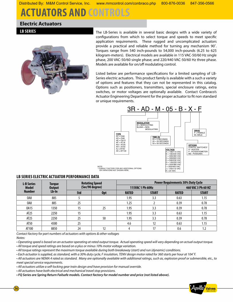
Electric ActuatorsLB SERIES The LB-Series is available in several basic designs with a wide variety of
configurations from which to select torque and speeds to meet specific application requirements. These rugged and uncomplicated actuators provide a practical and reliable method for turning any mechanism 90˚. Torques range from 540 inch-pounds to 54,000 inch-pounds (6.25 to 625 kilogram-meters). Electrical models are available in 115 VAC-50/60 Hz single phase, 200 VAC-50/60 single phase; and 220/440 VAC-50/60 Hz three phase. Models are available for on/off modulating control.
Listed below are performance specifications for a limited sampling of LB-Series electric actuators. This product family is available with a such a variety of options and features that they can not be represented in this catalog. Options such as positioners, transmitters, special enclosure ratings, extra switches, or motor voltages are optionally available. Contact Conbraco’s Actuator Engineering Department for the proper actuator to fit non standard or unique requirements.
LB SERIES ELECTRIC ACTUATOR PERFORMANCE DATA L-B Series
Model Number
TorqueOutput
Lb-In
Rotating Speed(Sec/90 degree)
Power Requirements 30% Duty Cycle115VAC 1 Ph 60Hz 460 VAC 3 Ph 60 HZ
Std Opt RATED START RATED START OA8 885 5 1.95 3.3 0.63 1.15 OA8 885 25 1.25 2 0.39 0.78
OA15 1350 15 25 1.95 3.3 0.39 0.78 AT25 2250 15 1.95 3.3 0.63 1.15 AT25 2250 25 50 1.95 3.3 0.39 0.78 AT50 4500 25 4.6 12 0.63 1.15
AT100 8850 24 12 4 17 0.6 1.2Contact factory for part numbers of actuators with options & other voltagesNotes:• Operating speed is based on an actuator operating at rated output torque. Actual operating speed will vary depending on actual output torque.• All torque and speed ratings are based on a plus or minus 10% motor voltage variation.• All torque ratings represent the maximum torque available during both breakaway (start) and run (dynamic) conditions.• Each actuator is supplied, as standard, with a 30% duty cycle, F insulation, TENV design motor rated for 360 starts per hour at 104˚F.• All actuators are NEMA 4 rated as standard. Many are optionally available with additional ratings, such as, explosion proof or submersible, etc., to meet special service requirements.• All actuators utilize a self-locking gear train design and have provision for manual override.• All actuators have both electrical and mechanical travel stop provisions.• FQ Series are Spring Return Failsafe models. Contact factory for model number and price (not listed above).
SCALE: DRN: CHKD: NO. REV.
NAME:
MAT'L:
EXP. NO.
CHANGE DESCRIPTION ECN NO. BY DATEREV.
APP'D:DATE:
NOTE: This drawing and the subject matter disclosed therein is the property of Conbraco Industries, Inc. and is not to becopied, used, appropriated or disclosed to others without the expressed written permission of Conbraco Industries, Inc.
NTS CRT 10/02/09 A
NUMBERING SYSTEM FOR BERNARD ACTUATORS
A CRT 10-20-15
R
3R - AD - M - 05 - B - X - F
TYPEAC = OA6AD = OA8AE = OA15AF = AT18AG = AT25AH = AT50AJ = BT50AK = BT100
MODULATIONM = MODULATINGBLANK = NON MODULATING
TIME (S)05 = 5 SECONDS25 = 25 SECONDS50 = 50 SECONDS
VOLTAGEA = 1/60/115 VACB = 1/60/220 VACC = 3/60/460 VACD = 3/60/600 VACE = 3/60/230 VACG = 1/50/220 VACH = 3/50/380 VACI = 3/50/400 VACJ = 1/50/115 VACK = 24 VDC
DRIVEF = FEMALEM= MALE
OPTIONSCONTOL SWITCHES*H - HEATERP - POTENTIOMETERMS - POSIGAM+
NOTE:* CONSULT FACTORY FOR ANY ADDITIONAL OPTIONS OR VARIATIONS NOT SHOWN HERE.
Distributed By: M&M Control Service, Inc. www.mmcontrol.com/conbraco.php 800-876-0036 847-356-0566
ACTUATORS AND CONTROLS
37
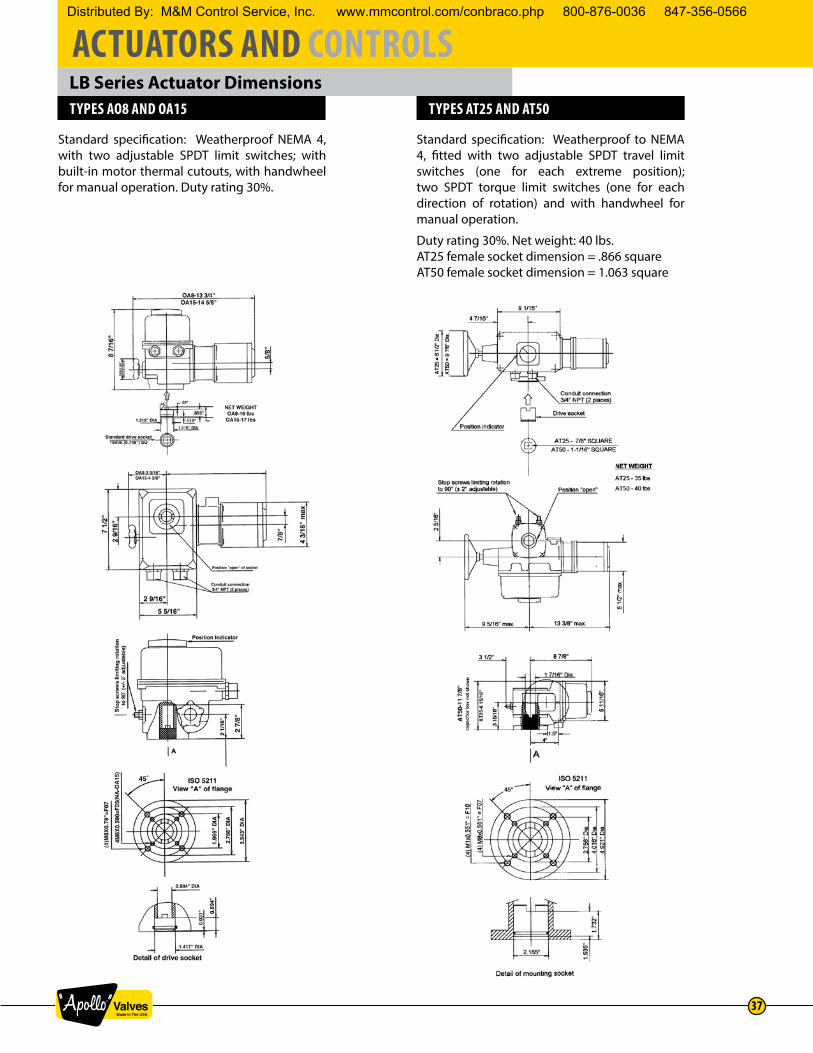
LB Series Actuator DimensionsTYPES AO8 AND OA15 TYPES AT25 AND AT50
Standard specification: Weatherproof NEMA 4, with two adjustable SPDT limit switches; with built-in motor thermal cutouts, with handwheel for manual operation. Duty rating 30%.
Standard specification: Weatherproof to NEMA 4, fitted with two adjustable SPDT travel limit switches (one for each extreme position); two SPDT torque limit switches (one for each direction of rotation) and with handwheel for manual operation.
Duty rating 30%. Net weight: 40 lbs. AT25 female socket dimension = .866 squareAT50 female socket dimension = 1.063 square
Distributed By: M&M Control Service, Inc. www.mmcontrol.com/conbraco.php 800-876-0036 847-356-0566
ACTUATORS AND CONTROLS
38
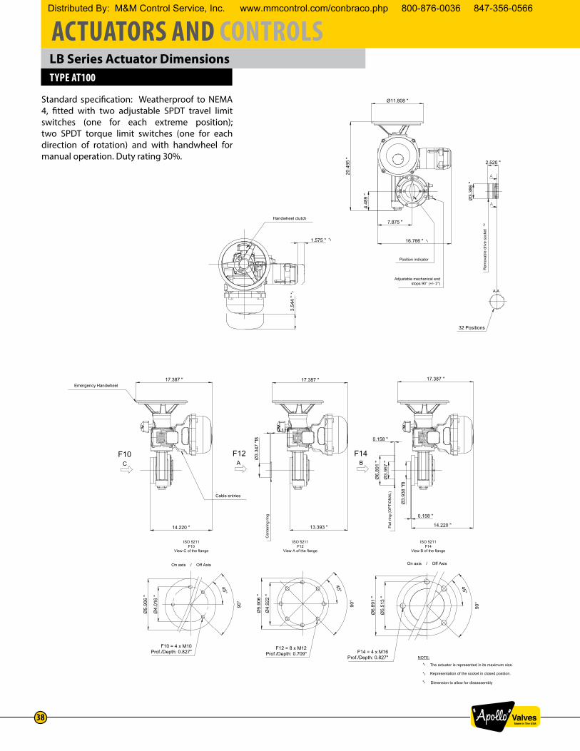
LB Series Actuator DimensionsTYPE AT100
Standard specification: Weatherproof to NEMA 4, fitted with two adjustable SPDT travel limit switches (one for each extreme position); two SPDT torque limit switches (one for each direction of rotation) and with handwheel for manual operation. Duty rating 30%.
The actuator is represented in its maximum size.
Representation of the socket in closed position.
Dimension to allow for dissassembly
NOTE:
*3
*2
*1
ISO 5211F12
View A of the flange
F14 = 4 x M16Prof./Depth: 0.827"
45°
90°
Ø6.
891
"
Ø5.
513
"
Ø5.
906
"
Ø4.
922
"
ISO 5211F14
View B of the flange
45°
90°
F12 = 8 x M12Prof./Depth: 0.709"
CF10
On axis / Off Axis
ISO 5211F10
View C of the flange
F10 = 4 x M10Prof./Depth: 0.827"
Ø5.
906
"
Ø4.
016
"
45°
90°
B
Flat
ring
(OP
TIO
NA
L)
F14
0.158 "
Ø6.
891
"
Ø3.
957
"
Ø3.
938
"f8
0.158 "
14.220 "
17.387 "
A
Cen
terin
g rin
g
F12
13.393 "
17.387 "
0.118 "
Ø3.
347
"f8
14.220 "
17.387 "
Cable entries
Emergency HandwheelØ11.808 "
Position indicator
Adjustable mechanical endstops 90° (+/- 2°)
A-A
32 Positions
Rem
ovab
le d
rive
sock
et*2
2.520 "
Ø3.
386
"
7.875 "
16.766 "
4.48
9 "
20.4
95 "
Handwheel clutch
*1
*33.
544
"
1.575 " *3
On axis / Off Axis
Distributed By: M&M Control Service, Inc. www.mmcontrol.com/conbraco.php 800-876-0036 847-356-0566