acu-trac level sensor configuration kit with rs-232
TRANSCRIPT

Acu-Trac™ Level Sensor Configuration Kit with RS-232 Adapter User’s
Guide
SSI TECHNOLOGIES, INC. Controls Division 1309 Plainfield Ave. Janesville, WI 53545-0450 Phone: (608)758-1500 Fax: (608) 758-2491 www.ssitechnologies.com
Page 1
Copyright August 29, 2012
SSI Technologies Inc. All Rights Reserved
Revision 2

SSI Technologies – Application Note AT-AN11 Acu-Trac™ Level Sensor Configuration Kit with RS-232 Adapter
User’s Guide
SSI TECHNOLOGIES, INC. Controls Division 1309 Plainfield Ave. Janesville, WI 53545-0450 Phone: (608)758-1500 Fax: (608) 758-2491 www.ssitechnologies.com
Copyright August 29, 2012 SSI Technologies Inc. All Rights Reserved
Revision 2
Page 2
Acu-Trac™ Technical Assistance
We can be reached online, via email, or by telephone and will be happy to assist you with any question you may have installing or using this product.
Online
If you’re looking for more information, technical data, application notes, or would like to see how the product is applied please view our website at:
http://ssitechnologies.com
On our website you’ll find a comprehensive technical library containing, product data sheets and application notes covering all of our Acu-Trac™ products.
If your question is technical in nature, and you can afford to wait for one business day, then we recommend emailing our technical service engineers. They can be reached via email at:
Please include your phone number, availability and a detailed description of your question and we’ll get back to you with in one business day.
Direct
If your need immediate assistance please call us direct. Our service engineers can be reached Monday through Friday from 8:00 AM to 5:00 PM CST.
(608) 758-1500
Ask For
Acu-Trac™ Technical Assistance
The Information in this document is supplied for the express purpose of installing and using the Acu-Trac™ Sensor. SSI is not an expert in your technical field and therefore does not warrant the suitability of this product, software or information for your intended application. SSI accepts no responsibility for misuse, misapplication or unauthorized modification of its products. SSI’s obligation is limited to the Acu-Trac®
sensor per the following terms and conditions:
Limited Warranty
All SSI products are warranted against defective materials and workmanship for a period of one (1) year from the date of delivery to the original purchaser. Any product that is found to be defective within the one year period will be replaced or repaired at the discretion of SSI. THIS WARRANTY IS IN LIEU OF ALL OTHER WARRANTIES, EXPRESS OR IMPLIED, OF MERCHANTABLITY, FITNESS FOR A PARTICULAR PURPOSE, PERFORMANCE, OR OTHERWISE. SSI is not an expert in the customer’s technical field and therefore does not warrant the suitability of its products for the applications selected by the customer. SSI accepts no responsibility for misuse, misapplication or unauthorized modification of its products. SSI’s obligation under this limited warranty is strictly and exclusively limited to the repair or replacement free of charge of such products as are to be found to be defective in material or workmanship on the condition that the purchaser gives prompt written notice to SSI of any claim to breach of warranty within the warranty period, and if requested, returns the defective product(s) to SSI. SSI will not assume any expenses or liability for repairs made to its products outside of its plant without its prior written consent. SSI reserves the right to satisfy its warranty obligation in full, with respect to defective products, by the payment to the purchaser of all sums paid by the purchaser to SSI for such products. IN NO EVENT SHALL SSI BE LIABLE FOR CLAIMS (BASED UPON BREACH OR EXPRESS OR IMPLIED WARRANTY, NEGLIGENCE OR OTHERWISE) FOR ANY DAMAGES, WHETHER DIRECT, IMMEDIATE, INCIDENTAL, FORSEEABLE, CONSEQUENTIAL, OR SPECIAL. SSI reserves the right to change its specifications at any time without notice.

SSI Technologies – Application Note AT-AN11 Acu-Trac™ Level Sensor Configuration Kit with RS-232 Adapter
User’s Guide
SSI TECHNOLOGIES, INC. Controls Division 1309 Plainfield Ave. Janesville, WI 53545-0450 Phone: (608)758-1500 Fax: (608) 758-2491 www.ssitechnologies.com
Copyright August 29, 2012 SSI Technologies Inc. All Rights Reserved
Revision 2
Page 3
Information is this document is subject to change without notice. No part of this document may be reproduced, stored in, or introduced into a retrieval system, or transmitted in any form or by any means without the express written consent of SSI Technologies Inc.
SSI Technologies Inc. has pending patents, copyrights and other intellectual property rights covering subject matter within this document. Except as expressly written in the software license agreement, the furnishing of this document does not give you any rights to the pending patents copyrights and other intellectual property covered herein.
Acu-Trac and SSI are registered trademarks of SSI Technologies Incorporated
Microsoft, Windows, Windows 98, Windows 2000, Windows NT are registered trademarks of the Microsoft Corporation.
© 2007 SSI Technologies Incorporated
All Rights Reserved
SSI Technologies – Application Note AT-AN11 Acu-Trac™ Level Sensor Configuration Kit with RS-232 Adapter
User’s Guide
SSI TECHNOLOGIES, INC. Controls Division 1309 Plainfield Ave. Janesville, WI 53545-0450 Phone: (608)758-1500 Fax: (608) 758-2491 www.ssitechnologies.com
Copyright August 29, 2012 SSI Technologies Inc. All Rights Reserved
Revision 2
Page 4
1 Introduction 5 2 Acu-Trac™ Level Sensor Configuration Kit Overview 6
2.1 Hardware 6 2.2 Software 6 2.3 Documentation 6
3 System Requirements 6 4 Acu-Trac™ Level Sensor Configuration Kit Contents & Description 7
4.1 Acu-Trac™ Ultrasonic Level Sensor 7 4.2 RS485 to RS232 Adapter 7 4.3 Acu-Trac™ Level Sensor Configuration CD-ROM 7 4.4 DB9 to DB25 PC Interface Cable 8 4.5 Documentation 8
5 Mounting the Sensor to the Tank 9 5.1 Mounting the Sensor to the Tank using the SAE bolt pattern 9 5.2 Mounting the Sensor to the Tank using the 1’ or 3/4” NPT Thread 9 5.3 Checking the Installation 9
6 Electrical Connections 10 6.1 Ground 10 6.2 Supply Voltage 11 6.3 Analog Output Connection 11 6.4 Data Link Positive (A) Connection 11 6.5 Data Link Negative (B) Connection 11 6.6 Data Link Adapter to PC Connection
7 Installing the Acu-Trac™ Level Sensor Configuration Software 11
12 7.1 License Agreement 12 7.2 COM Port Selection 13 7.3 Directory Location 14 7.4 Short Cut Folder Name 14 7.5 Load on Hard Drive 15 7.6 Complete Installation 15 7.7 Restart Selection 16
8 Starting the Acu-Trac™ Level Sensor Configuration Software 16
9 Acu-Trac™ Level Sensor Configuration Software Features & Description 17
9.1 Main Window Selections 17
9.2 User Buttons 19
9.3 System Setup Dialog 20
9.4 Level Sensor Monitor Dialog 21
9.5 Tank Profile Dialog 22
9.6 Analog Output Linear Settings 23
9.7 Learn Gauge 24
10 Error Messages 25
Appendix A: Acu-Trac™ Ultrasonic Sensor Family Analog Output Options 26
Glossary 27

SSI Technologies – Application Note AT-AN11 Acu-Trac™ Level Sensor Configuration Kit with RS-232 Adapter
User’s Guide
SSI TECHNOLOGIES, INC. Controls Division 1309 Plainfield Ave. Janesville, WI 53545-0450 Phone: (608)758-1500 Fax: (608) 758-2491 www.ssitechnologies.com
Copyright August 29, 2012 SSI Technologies Inc. All Rights Reserved
Revision 2
Page 5
1 Introduction
Thank you for purchasing a SSI Acu-Trac™ Level Sensor Configuration Kit. The system provides the user the following flexibility:
The ability to re-configure the Acu-Trac™ Level Sensor to support virtually any tank/barrel size or shape.
The ability to easily set up the Acu-Trac™ Level Sensor’s analog output to drive any gauge.
The ability to setup the communications mode and response time parameter.
SSI’s Acu-Trac™ technology automatically optimizes the level sensor’s operating parameters for level, motion, and ambient temperature, which improves performance, while delivering accurate level measurements day in and day out.
Converter - RS232 to RS485
DC Power Supply
RS-232
SAE J1708
DB9 to DB25 PC Interface Cable
Connect to the PC's Parallel Port 1 or 2
Acu-Trac™
LFDR. (OGNP+DT1.)2VGNDSIG. (B) (B) (A) (A)
+ Analog output - connection
Windows based PC
Electrical Connections Brown lead: connect to (+) terminal of
power supply Gray lead: connect to (-) terminal of
power supply White lead: connect to (A) lead of the
Converter Green lead: connect to (B) lead of the
Converter Yellow lead: Analog output connection
Sensor interface
harness assembly
Acu-Trac™ Sensor

SSI Technologies – Application Note AT-AN11 Acu-Trac™ Level Sensor Configuration Kit with RS-232 Adapter
User’s Guide
SSI TECHNOLOGIES, INC. Controls Division 1309 Plainfield Ave. Janesville, WI 53545-0450 Phone: (608)758-1500 Fax: (608) 758-2491 www.ssitechnologies.com
Copyright August 29, 2012 SSI Technologies Inc. All Rights Reserved
Revision 2
Page 6
2 Acu-Trac™ Level Sensor Configuration Kit Overview
The Acu-Trac™ Level Sensor Configuration Kit is designed to allow you to set up the Acu-Trac™ level sensor’s tank configuration and gauge drive from the convenience of your desk using a conventional Windows based PC. The kit comes complete with hardware, software, and application information.
2.1 Hardware
The hardware items included in this kit are a RS485 to RS232 Converter and a Level Sensor Interface Harness.
2.2 Software
The kit contains an easy to use Acu-Trac™ Level Sensor Configuration software package that can be simply installed off of the Acu-Trac™ Level Sensor Configuration Software CD ROM supplied with your kit. The software provides you with the ability to reconfigure the sensor for different barrel/tank sizes, and reconfigure the sensor for different gauge interfaces. The software application tools contained within this kit are as follows:
Acu-Trac™ Level Sensor Configuration Install Program:
Provides a standard Windows® install shield used to install the software, and setup the PC’s serial ports.
Acu-Trac™ Level Sensor Configuration Software:
The main application allows the user to:
• Read the sensor’s current configuration.
• Change the settings for the tanks size and shape, communications mode, and response time.
• Write the changes back to the sensor.
Learn Gauge: This window allows you to change the sensor’s analog output to correctly drive the fuel gauge.
Setup: This window allows you to change the RS232 serial port selection.
Monitor: This window allows you to monitor the outputs of the level sensor.
2.3 Documentation
Acu-Trac™ technical documents are available on our website www.ssitechnologies.com
3 System Requirements
The Acu-Trac™ Level Sensor Configuration software requires that you have a minimum system, which meets or exceeds the following:
Pentium® Processor-based personal computer or Laptop Windows® NT or Windows® 95 and above operating system CD-ROM Drive 64 MB of RAM memory

SSI Technologies – Application Note AT-AN11 Acu-Trac™ Level Sensor Configuration Kit with RS-232 Adapter
User’s Guide
SSI TECHNOLOGIES, INC. Controls Division 1309 Plainfield Ave. Janesville, WI 53545-0450 Phone: (608)758-1500 Fax: (608) 758-2491 www.ssitechnologies.com
Copyright August 29, 2012 SSI Technologies Inc. All Rights Reserved
Revision 2
Page 7
4 Acu-Trac™ Level Sensor Configuration Kit Contents & Description
The Acu-Trac™ Level Sensor Configuration Kit contains the following components:
• RS485 to RS232 Adapter
• Acu-Trac™ Level Sensor Configuration CD ROM
• DB9 to DB25 PC Interface Cable
• Documentation
4.1 Acu-Trac™ Ultrasonic Level Sensor (Sold Separately)
The Acu-Trac™ sensor is the heart of the level measurement system. The sensor calculates the distance to the target by generating a sound wave and then measuring the time necessary for the sound wave to travel from the sensor to the target and then back to the sensor again. The time of flight of the sound wave, or echo, provides the basis for the distance measurement. The speed of sound is constant; therefore, the distance is directly proportional to the measured time.
The Acu-Trac™ Ultrasonic Level Sensor used with this kit provides a RS485 digital communications output in addition to a re-configurable current or voltage output.
4.2 RS485 to RS232 Adapter
Acu-tracTM Sensor
Echo
Sound Wave
The RS485 to RS232 Adapter converts the RS485 sensor broadcasts into a conventional RS232 signal readable through your computer’s serial I/O port.
4.3 Acu-Trac™ Level Sensor Configuration CD-ROM
The Acu-Trac™ Level Sensor Configuration CD provides the software tools which will enable you to reconfigure the sensor for different tank sizes and gauges.
The Software Installation Guide in section 7 provides a step by step tutorial to guide you through the installation process.

SSI Technologies – Application Note AT-AN11 Acu-Trac™ Level Sensor Configuration Kit with RS-232 Adapter
User’s Guide
SSI TECHNOLOGIES, INC. Controls Division 1309 Plainfield Ave. Janesville, WI 53545-0450 Phone: (608)758-1500 Fax: (608) 758-2491 www.ssitechnologies.com
Copyright August 29, 2012 SSI Technologies Inc. All Rights Reserved
Revision 2
Page 8
4.4 DB9 to DB25 PC Interface Cable
Provides the RS232 serial data connection between your PC and the RS485 to RS232 Adapter.
DB9 Connecter DB25 Connecter
DB9 to DB25 PC Interface
Cable 4.5 Documentation
The following documents are available on line at our website, www.ssitechnologies.com
Acu-Trac™ Level Sensor Product Application Notes
Acu-Trac™ Level Sensor Configuration Kit User’s Guide – This manual. 5 Mounting the Sensor to the Tank 5.1 Mounting the Sensor to the Tank using the SAE bolt pattern
Position the level sensor gasket over the Acu-Trac™ level sensor assuring the proper screw hole alignment. Note: On a cylindrical tank the gasket is thinner in the middle than on the ends. Gasket alignment can be assured by holding the level sensor and gasket up to the light and rotate the gasket until light can be seen through all of the holes.
Insert the Acu-Trac® level sensor into the tank with the metal can facing down. Align the screw holes to the existing holes in the tank. Attach the level sensor to the tank using five screws.
SSI Technologies – Application Note AT-AN11 Acu-Trac™ Level Sensor Configuration Kit with RS-232 Adapter
User’s Guide
SSI TECHNOLOGIES, INC. Controls Division 1309 Plainfield Ave. Janesville, WI 53545-0450 Phone: (608)758-1500 Fax: (608) 758-2491 www.ssitechnologies.com
Copyright August 29, 2012 SSI Technologies Inc. All Rights Reserved
Revision 2
Page 9
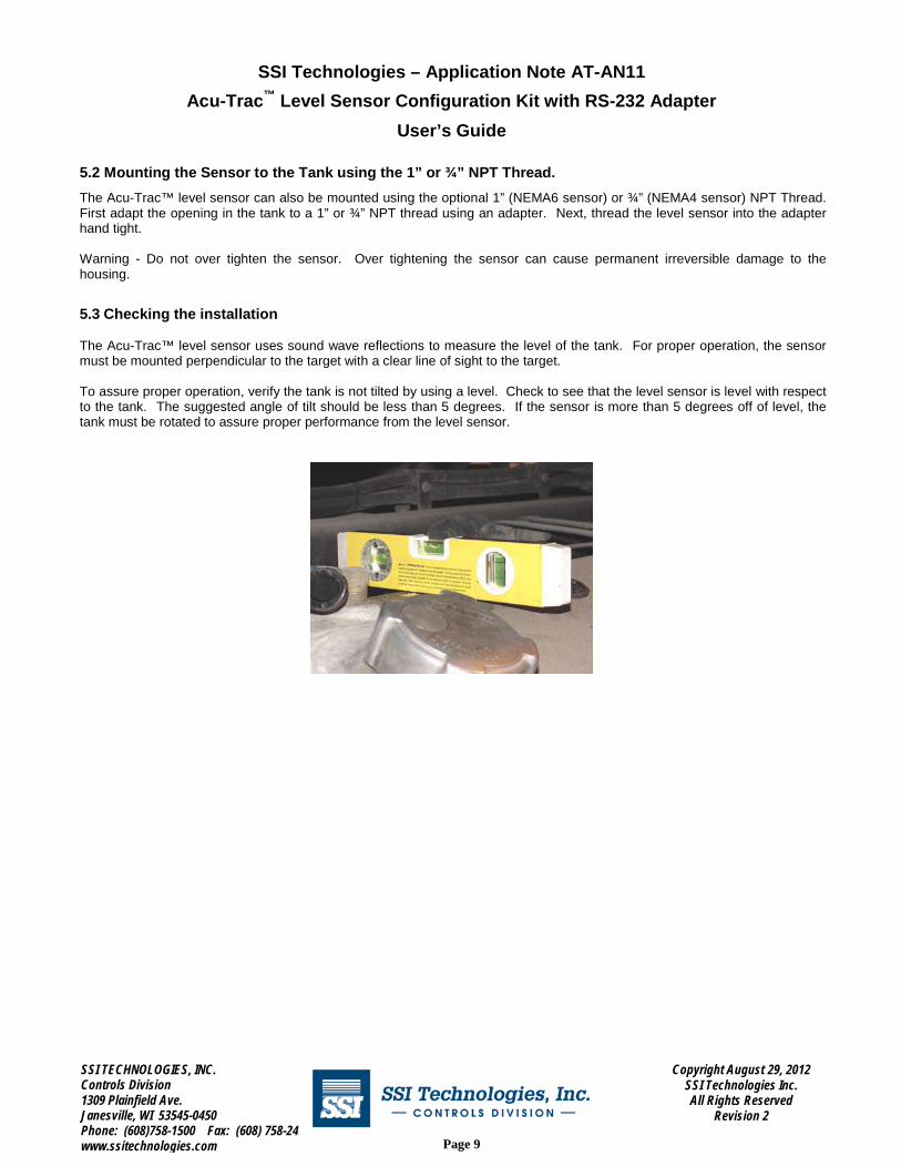
5.2 Mounting the Sensor to the Tank using the 1” or ¾” NPT Thread.
The Acu-Trac™ level sensor can also be mounted using the optional 1” (NEMA6 sensor) or ¾” (NEMA4 sensor) NPT Thread. First adapt the opening in the tank to a 1” or ¾” NPT thread using an adapter. Next, thread the level sensor into the adapter hand tight.
Warning - Do not over tighten the sensor. Over tightening the sensor can cause permanent irreversible damage to the housing.
5.3 Checking the installation
The Acu-Trac™ level sensor uses sound wave reflections to measure the level of the tank. For proper operation, the sensor must be mounted perpendicular to the target with a clear line of sight to the target.
To assure proper operation, verify the tank is not tilted by using a level. Check to see that the level sensor is level with respect to the tank. The suggested angle of tilt should be less than 5 degrees. If the sensor is more than 5 degrees off of level, the tank must be rotated to assure proper performance from the level sensor.

SSI TECHNOLOGIES, INC. Controls Division 1309 Plainfield Ave. Janesville, WI 53545-0450 Phone: (608)758-1500 Fax: (608) 758-2491 www.ssitechnologies.com
Copyright August 29, 2012 SSI Technologies Inc. All Rights Reserved
Revision 2
Page 10
SSI Technologies – Application Note AT-AN11 Acu-Trac™ Level Sensor Configuration Kit with RS-232 Adapter
User’s Guide
6 Electrical Connections
The electrical interface connection to the Acu-Trac™ level sensor is illustrated below. Figure 1 is for Acu-Trac™ with integral harness and Figure 2 is for Acu-Trac™ with Packard connector and Harness P/N 2436.3 (supplied in the configuration kit).
Power Supply - +
Acu-trac® Integral Harness
Grey Lead: Ground Brown Lead: Power
Green Lead: (B) Yellow Lead: Analog
White Lead: (A)
RS-485 to RS-232 Converter Serial Data
Bus Connections B
A
Figure 1 Acu-Trac™ with integral harness
Power Supply - +
Acu-trac™ 2436.3
Harness
Orange Lead : Ground
Red Lead: Power Green Lead: (B)
Yellow Lead: Analog Brown Lead: (A)
RS-485 to RS-232 Converter Serial Data
Bus Connections B
A
Figure 2 Acu-Trac™ with Packard connector
6.1 Ground
The ground lead must be connected to ground (battery negative) for the level sensor to function. The level sensor’s internal electronics are ground isolated from the tank to prevent ground loops. All sinked current will be returned through this connection.

SSI TECHNOLOGIES, INC. Controls Division 1309 Plainfield Ave. Janesville, WI 53545-0450 Phone: (608)758-1500 Fax: (608) 758-2491 www.ssitechnologies.com
Copyright August 29, 2012 SSI Technologies Inc. All Rights Reserved
Revision 2
Page 11
SSI Technologies – Application Note AT-AN11 Acu-Trac™ Level Sensor Configuration Kit with RS-232 Adapter
User’s Guide
6.2 Supply Voltage
The power lead must be connected to DC Power (Battery Positive) for the level sensor to function. The power source to the level sensor should contain a fuse with minimum amperage rating of 1 Amp and maximum amperage rating of 5 Amps. The level sensor will function when the supply voltage is between 11 and 16 Volts for the 12 Volt sensor and between 11 and 34 Volts for the 24 Volt sensor. This connection is protected from over voltage, load dumps, and other electrical transients.
6.3 Analog Output Connection
The Yellow lead is the analog output. Two different analog outputs are available depending on which level sensor was purchased. The voltage output part is primarily used to drive a gauge. The current output part is primarily used to interface with industrial equipment.
6.4 Data Link Positive (A) Connection
Connect the Data Link Positive (A) wire to the data link positive (A) connection on the RS-485 to RS-232 adapter (A) position.
6.5 Data Link Negative (B) Connection
Connect the data link negative (B) wire to the data link negative (B) connection on the RS-485 to RS-232 adapter (B) position.
6.6 Data Link Adapter to PC Connection
Prior to using the Level Sensor Configuration software, connect the DB25 Connector to the adapter and the DB9 Connector to your PC.
DB9 Connecter DB25 Connecter
DB9 to DB25 PC Interface
Cable

SSI TECHNOLOGIES, INC. Controls Division 1309 Plainfield Ave. Janesville, WI 53545-0450 Phone: (608)758-1500 Fax: (608) 758-2491 www.ssitechnologies.com
Copyright August 29, 2012 SSI Technologies Inc. All Rights Reserved
Revision 2
Page 12
SSI Technologies – Application Note AT-AN11 Acu-Trac™ Level Sensor Configuration Kit with RS-232 Adapter
User’s Guide
7 Installing the Acu-Trac™ Level Sensor Configuration Software
To Install the Level Sensor Configuration Software, insert the Acu-Trac™ Level Sensor Configuration CD into your CD ROM drive. Double click on the CD ROM drive icon located in MY Computer; the setup Welcome window will immediately appear with the following display:
We recommend that you close all Windows® applications before proceeding with the setup. To begin the installation process click next which will bring up the Software License Agreement window.
7.1 License Agreement
This program is protected by copyright law and international treaties. The unauthorized reproduction and distribution of this program may result in sever civil and criminal penalties and will be prosecuted to the maximum extent possible under law. Please read the licensing agreement carefully. Click Accept to continue the installation.

SSI TECHNOLOGIES, INC. Controls Division 1309 Plainfield Ave. Janesville, WI 53545-0450 Phone: (608)758-1500 Fax: (608) 758-2491 www.ssitechnologies.com
Copyright August 29, 2012 SSI Technologies Inc. All Rights Reserved
Revision 2
Page 13
SSI Technologies – Application Note AT-AN11 Acu-Trac™ Level Sensor Configuration Kit with RS-232 Adapter
User’s Guide
7.2 COM Port Selection
This window sets up the communications between your PC and the Acu-Trac™ sensor. Determine the correct COM port by looking on the back of your computer at the DB9 connector location that you used to plug in the PC Interface Cable during hardware setup. Next to, or above, the connector you will find a serial port designation that defines the communications port. It will either be COM 1 or COM2. Click on the correct COM port selection in the setup screen to retain your entry. Click next to continue the installation.
Note: The COM port selection can be changed after installation by
clicking on the Setup button from the Acu-Trac™ Level Sensor Configuration Software window. See section 9.2 for
additional details.
SSI TECHNOLOGIES, INC. Controls Division 1309 Plainfield Ave. Janesville, WI 53545-0450 Phone: (608)758-1500 Fax: (608) 758-2491 www.ssitechnologies.com
Copyright August 29, 2012 SSI Technologies Inc. All Rights Reserved
Revision 2
Page 14
SSI Technologies – Application Note AT-AN11 Acu-Trac™ Level Sensor Configuration Kit with RS-232 Adapter
User’s Guide
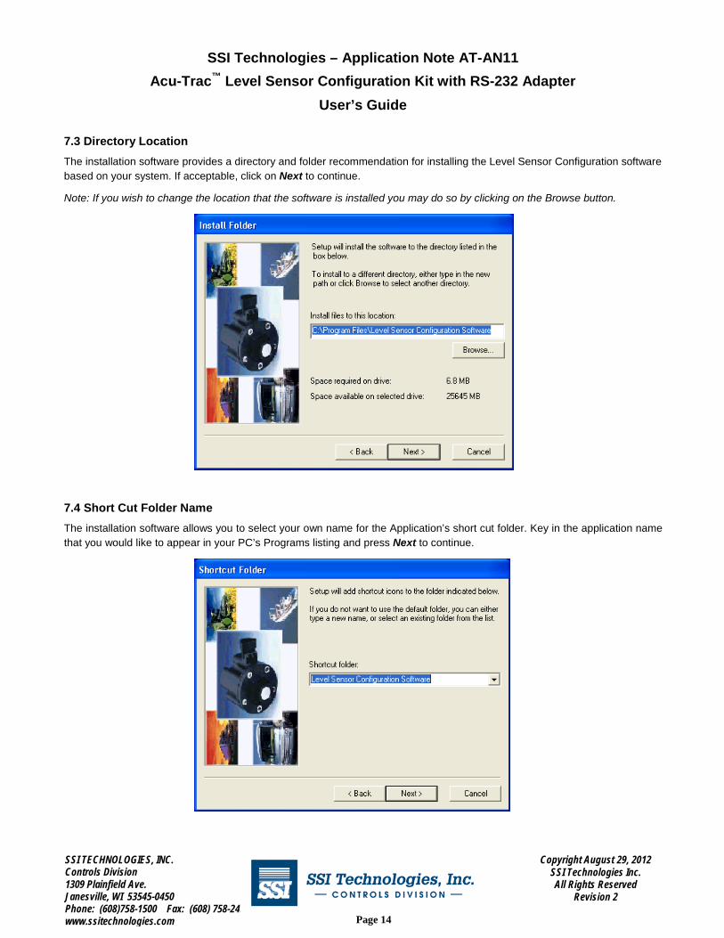
7.3 Directory Location
The installation software provides a directory and folder recommendation for installing the Level Sensor Configuration software based on your system. If acceptable, click on Next to continue.
Note: If you wish to change the location that the software is installed you may do so by clicking on the Browse button.
7.4 Short Cut Folder Name
The installation software allows you to select your own name for the Application’s short cut folder. Key in the application name that you would like to appear in your PC’s Programs listing and press Next to continue.

SSI TECHNOLOGIES, INC. Controls Division 1309 Plainfield Ave. Janesville, WI 53545-0450 Phone: (608)758-1500 Fax: (608) 758-2491 www.ssitechnologies.com
Copyright August 29, 2012 SSI Technologies Inc. All Rights Reserved
Revision 2
Page 15
SSI Technologies – Application Note AT-AN11 Acu-Trac™ Level Sensor Configuration Kit with RS-232 Adapter
User’s Guide
7.5 Load On Hard Drive
At this point the installation software has enough information to install the Level Sensor Configuration software onto your hard drive. Click on Install to automatically load the Level Sensor Configuration software onto your system and create an icon in your start menu.
7.6 Complete the Installation
The installation software will display the message Updating Your System while the installation proceeds. Upon completion the finished window will appear indicating that the installation has been completed.
Remove the Acu-Trac™ Level Sensor Configuration CD ROM from your CD ROM drive and click on Finish button when ready.

SSI TECHNOLOGIES, INC. Controls Division 1309 Plainfield Ave. Janesville, WI 53545-0450 Phone: (608)758-1500 Fax: (608) 758-2491 www.ssitechnologies.com
Copyright August 29, 2012 SSI Technologies Inc. All Rights Reserved
Revision 2
Page 16
SSI Technologies – Application Note AT-AN11 Acu-Trac™ Level Sensor Configuration Kit with RS-232 Adapter
User’s Guide
7.7 Restart Selection
Depending on your PC’s operating system, the installation may require you to restart your system to save the installed settings. You have the option to restart your system through the installation window by clicking on the Ok button or to restart your system manually using your Shut Down button at a later time.
Click on the Ok button to bring up the restart window. Click Ok to restart your system. The installation is now complete. The software will automatically shut down and restart your computer.
Note:
The Level Sensor Configuration software is installed onto your hard drive under the shortcut Name which was entered during
this installation. 8 Starting the Acu-Trac™ Level Sensor Configuration Software If you haven’t already installed the Acu-Trac™ Level Sensor Configuration software, you’ll need to do so before you can bring up the application. For installation instructions reference section 7.
To Start the Acu-Trac™ Level Sensor Configuration software on the Windows® Taskbar, click the Start button, point to Programs, point to the shortcut name you entered during installation and click on the Level Sensor Configuration Software.exe The Acu-Trac™ Level Sensor Configuration Software window will automatically open up providing the following display:

SSI TECHNOLOGIES, INC. Controls Division 1309 Plainfield Ave. Janesville, WI 53545-0450 Phone: (608)758-1500 Fax: (608) 758-2491 www.ssitechnologies.com
Copyright August 29, 2012 SSI Technologies Inc. All Rights Reserved
Revision 2
Page 17
SSI Technologies – Application Note AT-AN11 Acu-Trac™ Level Sensor Configuration Kit with RS-232 Adapter
User’s Guide
The Level Sensor Configuration Software allows you to change the tank’s size, depth and to compensate for offset mounting conditions. The picture below illustrates a typical tank application.
Mounting Offset
Tank Depth
Maximum Fill Level
9 Acu-Trac™ Level Sensor Configuration Software Features & Description 9.1 Main Window Selection
Cylindrical Tank Lying on its side:
For cylindrical tanks lying on their sides. The volume is not proportional to distance.
Tank Stands Up: For Cylindrical or Rectangular tanks standing up. The volume of the tank is
linear with respect to the distance from the top of the tank.
Non-Linear Tank The volume versus the distance relationship can also be specified in table form. Select “Non-Linear Tank” and click the “Tank Profile” button. Enter the volume for the tank in 5% increments and press “Okay”
SSI TECHNOLOGIES, INC. Controls Division 1309 Plainfield Ave. Janesville, WI 53545-0450 Phone: (608)758-1500 Fax: (608) 758-2491 www.ssitechnologies.com
Copyright August 29, 2012 SSI Technologies Inc. All Rights Reserved
Revision 2
Page 18
SSI Technologies – Application Note AT-AN11 Acu-Trac™ Level Sensor Configuration Kit with RS-232 Adapter
User’s Guide
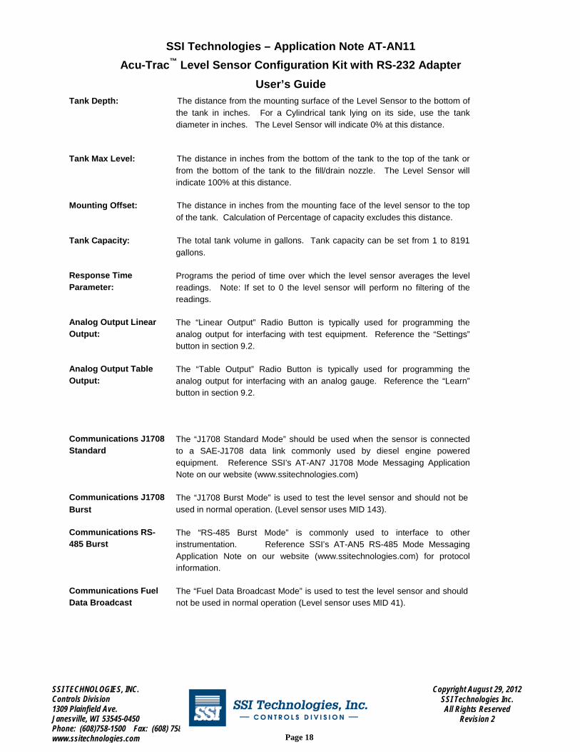
Tank Depth: The distance from the mounting surface of the Level Sensor to the bottom of
the tank in inches. For a Cylindrical tank lying on its side, use the tank diameter in inches. The Level Sensor will indicate 0% at this distance.
Tank Max Level: The distance in inches from the bottom of the tank to the top of the tank or from the bottom of the tank to the fill/drain nozzle. The Level Sensor will indicate 100% at this distance.
Mounting Offset: The distance in inches from the mounting face of the level sensor to the top
of the tank. Calculation of Percentage of capacity excludes this distance.
Tank Capacity: The total tank volume in gallons. Tank capacity can be set from 1 to 8191 gallons.
Response Time Parameter:
Programs the period of time over which the level sensor averages the level readings. Note: If set to 0 the level sensor will perform no filtering of the readings.
Analog Output Linear Output:
The “Linear Output” Radio Button is typically used for programming the analog output for interfacing with test equipment. Reference the “Settings” button in section 9.2.
Analog Output Table Output:
The “Table Output” Radio Button is typically used for programming the analog output for interfacing with an analog gauge. Reference the “Learn” button in section 9.2.
Communications J1708 Standard
The “J1708 Standard Mode” should be used when the sensor is connected to a SAE-J1708 data link commonly used by diesel engine powered equipment. Reference SSI’s AT-AN7 J1708 Mode Messaging Application Note on our website (www.ssitechnologies.com)
Communications J1708 Burst
The “J1708 Burst Mode” is used to test the level sensor and should not be used in normal operation. (Level sensor uses MID 143).
Communications RS- 485 Burst
The “RS-485 Burst Mode” is commonly used to interface to other instrumentation. Reference SSI’s AT-AN5 RS-485 Mode Messaging Application Note on our website (www.ssitechnologies.com) for protocol information.
Communications Fuel Data Broadcast
The “Fuel Data Broadcast Mode” is used to test the level sensor and should not be used in normal operation (Level sensor uses MID 41).

SSI TECHNOLOGIES, INC. Controls Division 1309 Plainfield Ave. Janesville, WI 53545-0450 Phone: (608)758-1500 Fax: (608) 758-2491 www.ssitechnologies.com
Copyright August 29, 2012 SSI Technologies Inc. All Rights Reserved
Revision 2
Page 19
SSI Technologies – Application Note AT-AN11 Acu-Trac™ Level Sensor Configuration Kit with RS-232 Adapter
User’s Guide
9.2 User Buttons
The Exit button is used to close the Acu-Trac™ Level Sensor Configuration window.
The Help button brings up the User Manual.
The Setup button is used to change the COM port selection. The Read button is used to read the current configuration of the level sensor. The Tank Profile button brings up the “Tank Profile” dialog. The Tank Profile dialog is used to enter a look up table that relates distance to volume. The Tank Profile button is initially “grayed out” to make sure the part is read prior to making changes to the settings.
The Learn button brings up the “Learn Gauge dialog” described in section 9.6. The Learn Gauge dialog is used to set the analog output to drive a custom gauge. The Learn button is initially “grayed out” to make sure the part is read prior to making changes to the settings.
The Settings button brings up the “Linear Settings” dialog. The Linear Settings dialog is commonly used to set the analog output to interface with test equipment. The Settings button is initially “grayed out” to make sure the part is read prior to making changes to the settings. The Monitor button brings up the “Level Sensor Monitor” dialog. The Level Sensor Monitor dialog can be used to monitor the Fuel Level Sensor outputs using your PC. Reference the Monitor section 9.3 for more information.
The Write button is used to write the settings (including the learned analog output settings) to the level sensor. It is initially “grayed out” to make sure the part is read prior to making changes to the settings.

SSI TECHNOLOGIES, INC. Controls Division 1309 Plainfield Ave. Janesville, WI 53545-0450 Phone: (608)758-1500 Fax: (608) 758-2491 www.ssitechnologies.com
Copyright August 29, 2012 SSI Technologies Inc. All Rights Reserved
Revision 2
Page 20
SSI Technologies – Application Note AT-AN11 Acu-Trac™ Level Sensor Configuration Kit with RS-232 Adapter
User’s Guide
9.3 System Setup Dialog
When the setup button is pressed the System Setup Dialog is displayed as follows:
The system setup dialog provides the means to change the communications port on your PC or the RS-485 to RS-232 adapter being used. The default settings are for COM 1 and the SSI supplied B&B 232SAER adapter provided with this kit.
9.4 Level Sensor Monitor Dialog
When the Monitor button is pressed the Level Sensor Monitor Dialog is displayed as follows:
Percent Capacity: The percentage of the current tank volume of the full tank volume.
Volume: The current tank volume typically in gallons.
SSI TECHNOLOGIES, INC. Controls Division 1309 Plainfield Ave. Janesville, WI 53545-0450 Phone: (608)758-1500 Fax: (608) 758-2491 www.ssitechnologies.com
Copyright August 29, 2012 SSI Technologies Inc. All Rights Reserved
Revision 2
Page 21
SSI Technologies – Application Note AT-AN11 Acu-Trac™ Level Sensor Configuration Kit with RS-232 Adapter
User’s Guide
Analog Output: The analog output setting for the sensor. This value is in Volts for a voltage output sensor or in
milli-Amps for a current output sensor.
Degrees Celsius: The temperature at the front face of the sensor.
Inches to Target: The distance from the mounting face of the sensor to top of the liquid being measured.
Diagnostic Code: The level sensor contains built in tests to determine the health of the sensor. A zero (0) indicates “No Faults”. A one (1) indicates “Active Fault”. A two (2) indicates “Inactive Fault”.

SSI TECHNOLOGIES, INC. Controls Division 1309 Plainfield Ave. Janesville, WI 53545-0450 Phone: (608)758-1500 Fax: (608) 758-2491 www.ssitechnologies.com
Copyright August 29, 2012 SSI Technologies Inc. All Rights Reserved
Revision 2
Page 22
SSI Technologies – Application Note AT-AN11 Acu-Trac™ Level Sensor Configuration Kit with RS-232 Adapter
User’s Guide
9.5 Tank Profile Dialog
The Tank Profile Dialog provides a method to enter a distance to volume “look-up” table into the level sensor. Commonly called a strapping table, the percent of volume versus the percent of distance is entered for each 5% change in distance.
The Tank Profile dialog is shown below for a Tank Depth of 23 inches and Tank Capacity of 180 gallons. The default values for this table were determined by dividing Tank Depth and Tank Capacity by 20. Modify the gallons setting using the edit boxes and click “OK” to save the results.

SSI TECHNOLOGIES, INC. Controls Division 1309 Plainfield Ave. Janesville, WI 53545-0450 Phone: (608)758-1500 Fax: (608) 758-2491 www.ssitechnologies.com
Copyright August 29, 2012 SSI Technologies Inc. All Rights Reserved
Revision 2
Page 23
SSI Technologies – Application Note AT-AN11 Acu-Trac™ Level Sensor Configuration Kit with RS-232 Adapter
User’s Guide
9.6 Analog Output Linear Settings
Select the “Linear Output” Radio button and click on the “Settings” button to bring up the Analog Output Linear Settings Dialog. This dialog supports both voltage and current output sensors. Using this dialog, the user can set the voltage or current when the Percent of Capacity is 100% (i.e. Full) and 0% (i.e. Empty).
This dialog also provides a method to configure the sensor for “Guard Banding”. If the user would like the analog output to indicate full when the level is above 95% of capacity, then 95 would be entered into the Guard Band High Edit Box. If the user would like the analog output to indicate empty below 5%, then the user would enter 5 into the Guard Band Low Edit Box.
Press the “OK” button to return to the main dialog and save the settings.

SSI TECHNOLOGIES, INC. Controls Division 1309 Plainfield Ave. Janesville, WI 53545-0450 Phone: (608)758-1500 Fax: (608) 758-2491 www.ssitechnologies.com
Copyright August 29, 2012 SSI Technologies Inc. All Rights Reserved
Revision 2
Page 24
SSI Technologies – Application Note AT-AN11 Acu-Trac™ Level Sensor Configuration Kit with RS-232 Adapter
User’s Guide
9.7 Learn Gauge
Select the “Table Output” Radio button and click on the “Learn” button to bring up the Learn Gauge Dialog. The current analog output settings will be shown as below:
This dialog can be used to establish five different set points for the analog output corresponding to ¼ tank increments. This dialog is typically used with an installed gauge. Connect the yellow analog output wire from the sensor to the sensor input on the gauge (usually labeled with an “S”). Adjust the Empty slide bar until the gauge reads empty. Adjust the 1/4 slide bar until the gauge reads ¼. Repeat for ½, ¾, and full.
This dialog also provides a method to configure the sensor for “Guard Banding”. If the user would like the analog output to indicate full when the level is above 95% of capacity, then 95 would be entered into the Full Tank Guard Band Edit Box. If the user would like the analog output to indicate empty below 5%, then the user would enter 5 into the Guard Band Low Edit Box.

SSI TECHNOLOGIES, INC. Controls Division 1309 Plainfield Ave. Janesville, WI 53545-0450 Phone: (608)758-1500 Fax: (608) 758-2491 www.ssitechnologies.com
Copyright August 29, 2012 SSI Technologies Inc. All Rights Reserved
Revision 2
Page 25
SSI Technologies – Application Note AT-AN11 Acu-Trac™ Level Sensor Configuration Kit with RS-232 Adapter
User’s Guide
10 Error Messages The Acu-Trac™ Level Sensor Configuration software provides the following error messages in response to the conditions noted below:
10.1 COM Port Connection Failure!!
The COM Port Connection Failure!! error message occurs when the Acu-Trac™ Level Sensor Configuration software is unable to communicate with the COM port. The software requires exclusive use of the COM port in order to communicate with the sensor. This error will occur if the COM port you selected is in use by another program. Typically Palm pilot software and some modem drivers automatically engage the COM port when your PC is turned on.
To correct click Ok on the error message and close out the Acu-Trac™ Level Sensor Configuration software. Locate and close out any Palm pilot, PDA, modem or any other applications that may be running that shares the COM port you selected at install. Reopen the Acu-Trac™ Level Sensor Configuration window and resume operation.
To avoid this occurrence in the future, close out any applications that share the COM port prior to pulling up the Acu-Trac™ Level Sensor Configuration software.
10.2 Send Parameter Data Failed!!
The Send Parameter Data Failed!! error message occurs when the Level Sensor Configuration software is unable to read or write the configuration parameters.
If this error message occurs, check to make sure that all the electrical connections are present and that the sensor that you wish to configure is powered up. Unplug all other sensors on the data link, bring up the Acu-Trac™ Level Sensor Software window and click on the Read button. Re-enter the variables and retry the configuration.
10.3 Failure reading Level Sensor. Check Connections!!!
The Failure reading Level Sensor Check Connections!!! error message occurs when the Level Sensor Configuration software is unable to communicate with the sensor. Check the following:
No Electrical Power - Check the DC power to the level sensor. DC power can be measured between pins A and B of the level sensor harness.
COM Port Selection entered incorrectly during installation- Bring up the Acu-Trac™ Level Sensor configuration
software window and click on the Setup button. From the Setup window click on the correct COM port selection and click Ok. (See section 7 titled Installing the Acu-Trac™ Level Sensor Configuration Software for further information regarding the sensor’s identification label.)
Level Sensor Harness Damaged or Unplugged – Check the level sensor harness and the connection from the RS485 to RS232 Adapter to the level sensor harness to make sure that the harness is not damaged. Check that it is plugged into the sensor.
RS232 Interface Cable Damaged or Unplugged – Check the RS232 Interface Cable connections from the RS485 to RS232 Adapter to your PC.
Bad PC Communications Port – Switch the RS232 Interface Cable connection to another COM port on your PC. Bring up the Acu-Trac™ Level Sensor Configuration Software and click on the Setup button. From the Setup Window click on the new COM port selection and click Ok.
Damaged or Bad Sensor – Disconnect the sensor and replace.

SSI TECHNOLOGIES, INC. Controls Division 1309 Plainfield Ave. Janesville, WI 53545-0450 Phone: (608)758-1500 Fax: (608) 758-2491 www.ssitechnologies.com
Copyright August 29, 2012 SSI Technologies Inc. All Rights Reserved
Revision 2
Page 26
SSI Technologies – Application Note AT-AN11 Acu-Trac™ Level Sensor Configuration Kit with RS-232 Adapter
User’s Guide
Appendix A: Acu-Trac™ Ultrasonic Sensor Family Analog Output Options
The Acu-Trac™ family of sensors offers a voltage, and current loop analog output option. Each option provides an analog output, which is proportional to the measured volume. The following is a brief description of the various output options.
Voltage Output
The Voltage Output is a highly accurate voltage drive capable of sourcing 5 mA’s of current. The output is pre set for 0.5 to 4.5 volt operation as delivered from the factory. The voltage output is also field configurable and can be programmed for operation between .5 to 9.5 volts.
The Voltage Output is ratio-metric with respect to the input supply voltage provided to the sensor. In effect the output will rise and fall proportional to fluctuations in the supply voltage. This feature allows the user to compensate and correct for supply variations as they occur which is useful when operating in a noisy environment.
Current Loop Output
The Current Loop Output configuration is a highly accurate 4 to 20 mA instrumentation current loop. The Current Loop Output can drive resistive loads ranging from 100 to 410 ohms.
SSI TECHNOLOGIES, INC. Controls Division 1309 Plainfield Ave. Janesville, WI 53545-0450 Phone: (608)758-1500 Fax: (608) 758-2491 www.ssitechnologies.com
Copyright August 29, 2012 SSI Technologies Inc. All Rights Reserved
Revision 2
Page 27
SSI Technologies – Application Note AT-AN11 Acu-Trac™ Level Sensor Configuration Kit with RS-232 Adapter
User’s Guide
Glossary
COM Port Common PC term used to designate a RS232 serial interface port built into a personal computer.
DB9 D Series 9 pin subminiature electrical connector.
DB25 D Series 25 pin subminiature electrical connector.
Diagnostics Term used to designate the testing of a products operational status.
Echo Refers to the returned sound wave after it reflects off an object.
Percent of Capacity
Numeric value applied to level sensing applications wherein the level is reported as a percentage of the vessel’s total capacity.
RS232 Common PC based serial interface protocol enabling communications between microcomputers.
RS485 TIA/EIA Standard defining the communications protocol for sending messages over a 2 wire bi-directional serial data interface. See TIA/EIA Standard TIA/EIA-485-A, “Electrical Characteristics of Generators and Receivers for Use in Balanced Digital Multipoint Systems.”
Serial Number Refers to the 8-digit identification number which is uniquely coded into every Acu-Trac®
sensor.
Serial port Same as COM Port