ad 283 395 - defense technical information center · ad 283 395 me armed services ... resin...
TRANSCRIPT
UNCLASSIFIED
AD 283 395
Me
ARMED SERVICES TECHNICAL INFORMATION AGENCYARLINGTON HALL STATIONARLINGTON 12, VIRGINIA
UNCLASSIFIED

NOTCE: When goverment or other drawings, speci-fications or other data are used for any purposeother than in connection with a definitely relatedgovernment procurement operation, the U. S.Government thereby incurs no responsibility, nor anyobligation whatsoever; and the fact that the Govern-ment may have formulated, furnished, or in any waysupplied the said dravings, specifications, or otherdata is not to be regarded by Implication or other-wise as in any manner licensing the holder or anyother person or corporation, or conveying any rightsor permission to manufacture, use or sell anypatented invention that may in any way be relatedthereto.
6"2- 4vi',
MOD R-3647
0
I STUDY OF THE USE OF PREIMPREGNATED
I ROVING WITH NUMERICALLY CONTROLLED*WINDING EQUIPMENT
L~gw
A DIVISIOI OF NORTH AMERICAN AVIATION, INC.6633 CANOGA AVENUE, CANOGA PARK, CALIFORNIA
CONTRACT NOw 61-0498-c (FBM)
N SEP 10 1962;
TISIA A
BUREAU OF NAVAL WEAPONS
SPECIAL PROJECTS OFFICEDEPARTMENT OF THE NAVY
WASHINGTON 25, D. C.

BestAvailable
Copy
Vi
R-3647 24
STUDY OF THE USE OF PREINT'REtATED
ROVING WITH NUMERICALLY CONTROLLED
WINDING EQUIMENT
A DIVISION OF NORTH AMERICAN AVIATION, INC.
6633 CANOGA AVENUECANOGA PARK, CALIFORNIA
Contract NOw 61-0498-c (F4)
PREPARED BYM. A. Leeds
Structural Plastics Department
APPROVED BY
R. R. MorinAssistant to the President
NO. OF PAGES_.7..& _x ± REVISIONS DATE
DATE REV. mY PAGES AFFECTED REM A R KS
FORM N 18.5 (PLATE)
A OIVISION OP t4ONT$ A046IVICAN AYIAION. IN.
FOREWORD
This final report covers the work performed under
Contract NOw 61-0498-(FBM) for the Special Projects
Office, Bureau of Naval Weapons, Department of the Navy.
ABSTRACT
The advantages of preimpregnated roving, especially
for use in numerically tape-controlled winding equip-
ment, are recognized. This has led to the need for
more extensive knowledge of the relationship of mate-
rials properties and process parameters as they affect
the properties of filament-wound structures. This
program of study covered the following items related
to use of preimpregnated roving: (1) storage and
preheating conditions, (2) winding tension and roving
resin content, (3) tackiness and volatile content of
the roving strand, (4) preimpregnated roving package
design, (5) design of winding equipment components,
and (6) voids content in the laminate and variation
in strand width. A new tackiness test developed for
preimpregnated roving is discussed. A strand tensile
strength test on uncured roving was performed and its
potential use for quality control purposes discussed.
A preliminary process specification for use of preim-
pregnated roving, employing program results, has been
written.R-3647 iii
FORM 601. PLATE REV. 1.56

A DIVISION OP1 NORITH AMEICACN AVIATION. ING6
ACIGNOWLEDGMMN
The work for this program was performed within the
Structural Plastics Department and with the assistance
of several members of the department. Special acknowl-
edgment is made to John Leigh who assisted in writing
much of the material.
iv R-3647
FORM S0S-S PLATE REV. I-IS

3WP4 U CUM~rD"rME7A DIVIION 6P No~eTH AKIRIAN AVIATION. INC.
CONTENTS
Foreword................... . . . . i
Acknowledgmient . . . . . . . iv
Introduction . . . . . . . 0. ... .. ..... . .
Objectives . . . . . . . . . . . 7
Summary and. Conclusions .... . . . . . . . .9
Evaluation Methods . . . . . . . . . . 9
Materials .. . 10
Storage anxdPreheating Conditions . . . . . .. ..... 10
Winding Tension andResin Content . ..... 0.... 12
Tackiness and Volatile Content..............13
Packaging ......... ........... 15
Winding Machine Components........... . 16
Optimum Tensioning Technique...............19
ControlledStrandTension .. .. ... ... ... .. 19
Methods for Winding with Multiple Strands,...........19
Accurate Placement of Strands During Winding Operations . . . .. 20
Quality Control...................20
Came Winding Studies.............. . .. .... . 21
Discussion . .. . 0........... 0 .23
E'valuation Methods . . 23
Testing andvaluation . . 26
Winding Tension and Resin Content .39
.9trand.Tensile Strength . . . ..... .. . . 8
Case Winding Studie .................. 107
Objectives anxd Test Program............ 107
R-361k7
A DIVaGI@N 60 N0RT14 AMBUI@AN AVIATION. INC.
Discussion of Test Results............... 122
Process Specification . . . .. .. ... ... .... 129
Recommuendations.... ... ... ..... .... 131
Appendix... ... ............ .... 133
Design and. Test Procedure of 3-Inch-Diameter by
6.37-Inch-Long Cylindrical Test Specimen of
Filament-Wound. Construction.... ... ... .... 133
Material Specification for Glass Roving, Epoxy Resin
Impregnated, Uncured...... ... ... ... .. 151
vi R-364&7
FORM 600.3 PLATE RqEV. 1-50

A OIVIGION Op NORTH AM RNICAN AVIATION. INC.
ILLUSTIRATIONS
1. Test Pattern Applied. Using Numerically Controlled,
Winding Machine ........ ................. 1
2. Test Case, ABL 6400A ...... ............... 25
3. Cylindrical Specimen Winding Machine with
Roving Heating Device ...... . .............. 28
4. Effect of Room Temperature Storage of Preimpregnation
Roving and Process Parameters of Hoop Tensile Strength .... 29
5. Effect of Refrigerated Storage of Preimpregnated Roving
and Proc... Parameters on Hoop Tensile Strength ...... 31
6. Effects of Deep-Freeze Storage of Preimpregnated Roving
and Process Parameters on Hoop Tensile Strength ...... 32
7. Strands of Preimpregnated. Roving Showing the Permanent
Twist and. Wrinkles Created in the Package of Aged.
Material and. Not Present in Fresh Material . ......... 34
8. Uncured Specimens Wound with Aged. Preimpregnated
Roving Using Three Processing Techniques ..... ....... 35
9. Cured Specimens Wound. with Aged. Preimpregnated. Roving
Using Three Processing Techniques .............. 36
10. Cured. Specimens Wound with Aged. Preimpregnated.
Roving From Different Portions of the Same Spool . ...... 37
11. Effect of Roving Resin Content on Hoop Stress of
3-inch-Diameter Cylinders . . .............. 4012. The Effect of Winding Tension and Roving Resin Content
on Hoop Stress of 3-inch-Diameter Cylinders . .... . 41
13. Effect of Tension and Roving Resin Content
on Interlaminar Shear ..................... . 43
14. Mode of Failure of Hydrostatically Tested. Specimens . . . . . 44
R-3647 vii
FORM 800.3 PLATE REV, I.-O
A DIVISIlON OV NOT14 ANUNIGAN AVIATION. ING.
15. Cylindrical Samples Shoving the Effect of Winding Tension
on Resin Migration (13 to 17 percent resin) .... .... . 46
16. Cylindrical Samples Showing the Effect of Winding Tension
on Resin Migration (16 to 20 percent resin) .... .... . 47
17. Effect of Tension and Roving Resin Content on
Resin Migration ...... .. ............. . 50
18. Effect of Mandrel Diameter and. Roving Tension on Resin
Migration o.... .................. 5119. Effect of Radial Load on Resin Migration .......... 53
20. Tackiness Tester for Preimpregnated Roving . ....... 65
21. Tackiness Testing Device .... ............ . 66
22. Effect of Aging on Tackiness and Volatile Content . . ... 69
23. Winding Pattern for Study of the Effect of Preimpregnated
Roving Tackiness on the Ability to Wind an Unstable Pattern . 72
24. Winding Low-Tack Preimpregnated. Roving on a Bare Mandrel . . . 74
25. Winding High-Tack Preimpregnated. Roving on a Bare Mandrel . 75
26. Winding Preimpregnated. Roving Over a Wrap of
Preimpregnated Roving ..... .............. 77
27. Calculation of Effective L/D Ratio for Tackiness Study . 80
28. Over-all View of Test Pattern Performed. by NTC
Machine Using Pattern Thread ...... ........... . 82
29. EnAd View of Test Pattern Performed by NTC Machine
Using Cotton Thread ....... ................ 83
30. Fixture for Strand. Tensile Test .... ........... 85
31. Examples of Two Different Types of Preimpregnated.
Roving Package ........ ................. 92
32. Experimental Pulley Setup ..... ............. 93
33. Parallel-Wound Package of Preimprognated Roving
Where Tension Had Been Applied at the Package . . . ... 95
34. Experimental Pulley Setup ..... ............. 101
(.)
viii R-3647
FORM 608.1 PLATIC REV. 1-50

SA DIVIGION OP NORT64 AMI@AC AVIATION. ING.
35. Experimental Pulley Setup ..... ............. 103
36. Case S/N 4 Before Test ..................... 111
37. Hydrostatic Test Fixture for 18-inch-Diameter
by 24-inch-Long Cases . . . ............... 114
38. Case S/N4 After Burst Test, . . . ............ 116
39. Cases S/N 2 and.S/N 3 After Burst Test . . ........ 117
40. Case ABL 10 After Burst Test . . . . . .......... 118
41. Case SIN 5 After Burst Test . . ............. 119
42. Case S/N 6 After Burst Test . . . . . . . 120
43. Case S/N 2 Before Burst, Backlighted to Show Casing 121
44. Filament-Wound. Cylindrical Test Specimen . ..... . 134
45. Cylindrical Tout Specimen andHydrostatic
Test Fixture ....... ........ . . . ...... 138
46. Burst-Tested 3-inch-Diameter Test Cylinder . ....... 139
47. Interlaminar Shear Test ...................... .... 140
48. Hydrostatic Pressure Test Fixture ... .......... 165
49. Ring Specimen ........ ................. 168
50. Horizontal Shear Specimens and Test Setup .. ........ 169
R-3647 ix
FORM lOI5 PLATE REV, 1.35
A OIVISION O NORTH AM6NICAN AVIATION. ING 0
TABLE
1. Advantages of Preimpregnated Roving Over the
Wet Winding System ..... .... ............... 2
2. Data on Resin Content and. Hoop Tensile Strength
for Migration Studies of Thick-Walled.
3-inch-Diameter Cylinders ..... ............ 553. Relationship of Tension and Roving Resin Content to
Resin Migration, 3-inch-Diameter Thin-Walled.
(0.060-inch-Thick) Cylinders .... ........... 57
4. Relationship of Tension and Roving Resin Content
to Resin Migration (3-inch-Diameter Cylinders with
0.120-inch Nominal Wall Thickness) ... ......... 58
5. Tackiness Test Values ...... .............. 676. Property Data of Roving Used for Tension and.
Resin Content Study ...... .............. 70
7. The Influence of Tackiness on the Ability to
Wind an Unstable Pattern ...... ............. 78
8. Strand Tensile Strengths of Uncured Preimpregnated
Roving ..... ...... ............ 87
9. Tensile Strength of Uncured Preimpregnated Roving
from Single Spool ................... 88
10. Tensile Strength of Uncured. Preimpregnated Roving . . .. 89
11. Tensile Strength of Uncured Preimpregnated Roving
Stored at Room Temperature ..... ............ 90
12. Effect on Test Cylinder of Applying Tension to
Roving Package and, to Strand. .... ............ 96
13. Test Results of Cylinders Wound. Using Ceramic Bushing
and. Steel Pulley Roving Guides .... ........... 99
x R-3647
FORM 608.0 PLATE REV. 1-5
A DIVIGION OPr NoW Frm AmmfiscAN AVIATow. mNa
1k. Evaluation of the Effects of a Multiple Pulley Feed, System
f or Use vith Preimpregnated. Roving . . . . . 103
15. Data for 18-inch-Diameter by 24-inch-Ling Cases . . 110
16. Physical Properties of Preimpregnated, Roving............154
R-3647 xi
FORM 600g0 PLATE REV. 1-90

A OIVIOION OP NOMTM AI URMAN AVIATION. ING,
INTRODUCTION
Filament winding as a technique for manufacturing high-strength, precision
components such as radomes, pressure vessels and rocket motor cases has, in
the past, mainly utilized fiberglass roving and liquid resin applied to a
mandrel by a mechanical winding machine. The roving has been impregnated
with the resin at the winding machine. This system, called the wet winding
system, has certain inherent difficulties which can be overcome by the use
of roving preimpregnated with resin. Table 1 lists some of the advantages
of preimpregnated roving, with the corresponding shortcomings of the wet
J system, also listed.
The use of mechanically controlled winding machines has a number of draw-
backs. In general, these machines utilize a combination of cams, gears,
sprocket wheels, or feed screws to control the relative motion between
-the rotating mandrel and roving delivery device. This requires time-
consuming delays to change winding angles or pattern, and involves main-
tenance of a stock of gears and use of expensive cams, the manufacture of
which requires many hours of design calculations and complex machining.
Errors in setup or variations in pattern during winding may go undetected
until too late to correct the part being wound. These errors could be
chargeable to wear on the cams and gears in continuous use. Errors also
can occur because of slop and backlash in mechanical, linkages. Many me-
chanically controlled machines are also very limited as to the shape of
parts which can be successfully wound. "
The use of numerically controlled winding equipment overcomes these dis-
ad.ani.ages afnd, at the same 'time, offers these many advantages:
R-3647
FORM GO4.E PLATE RfVl -5

A SIVISiON OF NOmMH AUICAN AVIATI,@N. SNG.
TABLE I
ADVANTAGES OF PREIMPREGNATED ROVING
OVER THE WET WINDING SYSTEM
Preimpregnated Roving WLSystem
1. Laminates are not subject to large 1. Laminates are subject to mi-variations in resin content caused gration of resin to outsideby changes in tension, layers and subsequently non-
uniform resin content through-out thickness of wall.
2. Resin content in laminates is af- 2. Low resin content cannot befected less by diameter of mandrel, obtained on large-diameter
parts because of inability toobtain high enough tension.
3. All resin systems can 'be used, even 3. Many variables require controlthose requiring sol,ents, to ensure uniform resin content.
4. Long shelf life at room tempera- 4. Has limited winding speed be-ture permits fabrication of articles cause of the risk of throwingrequiring extended pro.essing time. resin off the mandrel at high
,rotation speeds.
5. Mandrels may be rotated at high 5. Is inherently messy, requiringspeed to allow more rapid fabrica- time consuming cleanuption and shorter production time. operations.
6. The roving ha6 good storage life 6. The wet system requires use ofunder refrigeration. Ii; requires weighing and mixing equipment.no special preparation for use.
7. Properties of a given lot of roy- 7. Rapid feed of roving createsing can readily 'be determined by impregnation problems.means of quality conurol methodsapplied before winding operation.
8. It eliminates the steps of wet resin 8. The wet system cannot use resinimpregnation and drainage, systems that require use of
solvent.
9. I ; is unnecessary to mix resin andhardener with inherent risk of error.
10. Preimpregnated roving may 'be used towind more unstable patterns vithoutslippage.
2 R-3647
FORM 609-5 PLATS REV. I-U8
iA
A DIVISION OP NORN AMKRICAN AVIATION. INC.
1. Versatility: A numerically controlled filament winding machine
can be programmed for any winding operation within its range by
simply changing the control tape. In addition, this allows a
series of winding operations to be run in rapid sequence. No
time delaying change in mechanical setup is required. Many dif-
ferent shapes (;an be readily wound.
2. Accuracy: Numerically controlled equipment is capable of pre-
cise winding patterns. A demonstration of this is shown in Fig.
1. This pattern was applied by a Rocketdyne numerically con-
trolled machine. Accuracy in pattern laydown is believed to be
significant in producing optimum strength properties in filament-
wound structures. The ability of numerically controlled equip-
menrt to make reproducible filament-wound structures eliminates
variables in the performance of these structures.
3. Operation Speed: The use of digital programming elements and
rapid hydraulic, drive mechanisms on the Rocketdyne filament
winding equipment will provide high operational speeds to meet
any produt tion requirements.
4. Quality Control. fhe accuracy and reproducibility of filament-
wound patterns fab ricat ed on numerically controlled equipment
contribute to the effectiveness of quality control procedures.
The recording equipment associated with these machines will
also assist in qualify control proedures.
5. Storage: Any winding patern can be readily stored in the form
of a deck of puch cards and/or digi-i-al tape for any required
fut,are use. This, in effevt, means that numerically controlled
_) winding equipment can be immediately staged for any operation
for which a t ontrol tape has been previously prepared.
R-3647 3
*W~Mb an .. al a,. W. *.1

A IION OF NOHTI-I AMERICAN AVIATION INC
ISI1:4PL,
' *0
U)UW
-q
t 1 R-3647
A DIVISION Or NORTH AMKNICAN AVIATION. INC.
Because of the advantages listed, it was decided that filament winding of
efficient struxctures could best be accomplished by using preimpregnated
roving with numerically controlled equipment. It was also realized that
attainment of these efficient filament-wound laminates using preimpregnated
roving and numerically control]ed equipment would require factual informa-
tion concerning the materials and processes inivolved. This need has led
to the following program.
R-3647 5
FORM 608-8 PLATE REV. 1-bG

A OIVIGION OF NONH AMUNICAN AVIATION. INC.
OBJECTIVES
The program undertaken has as its objective the development of optimum
processing methods for fabricating rocket motor cases, tanks, and other
parts from preimpregnated roving using numerically controlled equipment.
This objective was accomplished by performance of these activilies:
I. Determination of the properties required of preimpregnated
roving for its most efficient use with numerically controlled
winding machines
2. Determination of the most favorable conditions for handling
preimpregnated roving both in storage and during fabrication
3. Determination of winding machinery modifications required when
preimpregnated roving is used in conjunction with high-speed
numerically control led winding equipment
.. Wri ting wtandard procedures for quality cont.rol and fabrica-
JITon methods for the use of preimp:regnated roving wil:h numeri-
cal Iv controlled machinery, and incorporating these procedures
inio a process specificailon
Items I through 3 were approached through a i;e.ting and evaluation program
using cylindrical filament-wound test, cylinders and wound vessels per
ABL print, b400A as Ghe test items. Data obtained were used in writ ing a
process specification which describes requirements of preimpregnated roviing,
machinery, and processing methods for the use of preimpregnated roving with
numerita ilv cordrolled equipment.
R-36k7 7
FORM 0-1 PLATE REV. I*RS
A DIVISION O NOWVM AMNSIGAN AVIATION. INCL
The testing and evaluation program encompassed these areas of investigation:
1. Resin advancement as it occurs during various storage conditions
and preheating conditions
2. Winding tension and resin content as they affect properties of
laminates
3. Tackiness and volatile content as they affect processing conditions
4. Packaging and how it affects processing
5. The effect, of voids content and variation in strand width on the
strength of laminates
6. Optimum design of winding equipment components
Results obtained in each area will be covered in the following discussion.
The parameters of principal interest were those which can be controlled
during the winding process. It is recognized that many of these parameters
are interrelated. However, the test procedures were, in most cases, limited
to evaluation of simple interactions such as the effect of winding tension
on resin migration. Multiple factor correlation of four or five variables
on a simul taneous basis was not attempted in this program. Rocketdyne's
numerically controlled filament winding machines were specifically designed
to use preimpregnated ro-%'ing and were used for the winding of ABL qua]ifica-
tion tanks and the s,;udy of optimum winding methods. Vatious types of pre-
impregnated roving hand]lng equipment were studied for use with this machine.
Study of resin systems or fiberglass materials was not an objective of this
program. Consequently, the entire test and evaluation program was performed
with one ma, ,eriai system.
8 R-3647
FORM 0OS-5 PLATE REV. 1I-S8

A c8ovisom or NORib4 AmERItAN AVIATION. Iov
SUMMARY AND CONCLUSIONS
In -his program, Rocketdyne has conducted an evaluation of some of the
basic properties of preimpregnated roving and its use in numerically tape-
controlled winding equipment. The emphasis in this study was to determine
the practical considerations related to -the use of these materials in
product ion situations.
EVALUATION METHODS
Investigation of the various materials properties and process parameters
was accomplished in most instances by fabrication of two test sample con-figurations, as fo'llows:
1. A cylindrical sample 3 inches in diameter by 6.37 inches long.
This specimen was iested by hydrostatic pressure to burst
failure. Ultimat-e hoop tensile stress was calculated, using
ithe pressure at failure. Another test applied to the cylinder
was parallel interlaminar shear performed on small ring seg-
men-Is cut! from ihe sample.
2. A pressure vessel 18 inches in diameter by 24 inches long. This
case conforms to the ABL600A design. Testing was by hydrostatic
pressure test, to burst failure.
Two other tests used were developed during -the investigation. These are a
strand tensile st.rengih test and a test for ta(kiness of the preimpregnated
roving strand. In 'the latter, a nmber value indicating the tackiness of
the roving results from performance of the test.
R-3647 9
FORM 601.1 PLATs REV. 1-06

A oVISION OP NORT AVA609*IAN AVIATION. IN.
MATERIALS
Because of limitations on available funds, only one resin system could be
used throughout the program. The material chosen for the specimen studies
was ECGI4O-20 end roving with Owens Corning 801 sizing impregnated with
E787, a proprietary epoxy resin system of U. S. Polymeric Chemicals, Inc.
E-HTS fiberglass roving impregnated with the same resin was used for the
studies involving the 18-inch-diameter cases.
STORAGE AND PREHEATING CONDITIONS
An extensive program was conducted to determine the effect of various con-
ditions of storing preimpregnated roving preliminary to the winding process.
Evaluations were made of the continued usefulness of roving stored at (1) O
room temperatures at 70 to 90 F, (2) refrigerator temperatures 40 to 50 F,
and (3) deep-freeze temperatfures -'10 to -:40 F.
Evaluations of the roving were made on 3-inch-diameter x 6.37-inch-long
cylinders tested to burst by hydrostatic pressure. The test cylinders were
fabricated under -three condiiions during the winding operations:
1. The cylinders were wound on a heated mandrel,followed by an oven
cure. Mandrels were preheated to 150 F.
2. The roving strand was heated during the winding operation with
i-,he mandrel at room temperature, followed by an oven cure. Tempera-
ture of the roving was approximately 125 F.
S
10 R-3647
FORM OO-l0 PLATE REV. -lbS
A 0WISION OP NORN AUSRICAN AVIATION. INC.
3. The roving strand was wrapped cold (without any heating of the
strand or mandrel), followed by an oven cure. The following
conclusions were reached from -this 6-month evaluation.
Storage at room temperatures (75 to 85 F) resulted in deterioration of
the material within 7 days. (For the purpose of evaluation, preimpregnated
roving was considered to have deteriorated or be nonusable when it gave
hoop tensile strength values with the 3-inch-diameter cylindrical specimens
below the average -range of values obtained from fresh material.)
Storage at refrigerator temperatures (35 to 45 F) was effective for periods
up to 6 months. The preimpregnated roving gave hoop tensile strength values
equivalent to the average range of results obtained from fresh material
throughout the evaluation. However, some loss in strand pliability and
tackiness was noted after approximately 3 months.
Preimpregnated roving can be stored at. deep freeze temperatures (-10 to -:. 10 F)
for periods up to b months and still give hoop tensile strength values equiv-
alent Lo fresh material. In addition, there was no apparent loss in strand
pliabili,y or iackiness after the materials we're brought to run temperature.
Preheating of the mandrel or material will extend the useful life of material
stored at room temperature up to 26 days (conclusion of test). The heat re-
stores the tackiness and pliability of the roving and provides for proper
consolidation during winding.
Preheating the mandrels or material when using "fresh" material does not im-
prove the physical strength of the laminate over that obtained without
prehea, iing.
R-3647 11
FORM 6o-0 PLATE REV, 1-0
A DIV11ON OP NORT4 AUUNIOAN AVIATO@ INS.
iC
It is recommended, when using the E787 resin system in a preimpregnated
roving, that the material be stored at deep-freeze temperatures to ensure
that the material remains fresh, and that no preheating need be used with
this material.
WINDING TENSION AND RESIN CONTENT
The objective of this program was to determine the effects of strand wind-
ing tension, resin content, and resin migration on the properties of
filament-wound laminates. Evaluation was performed by winding 3-inch-
diameter cylinders and testing for hoop tensile strength and interlaminar
shear strength. In the resin migration studies, 2-inch-wide bands were
wound on various-diameter mandrels.
The effects of roving resin content and winding tension on hoop tensile
strength and interlaminar shear strength can be summarized as follows:
1. Optimum tensile strength is obtained with roving which has a
resin content, of 17 to 20 percent and has been wound at 0.8 to
1.0 pound per end on a 20-end strand.
2. Optimum shear strength is obtained when winding with a strand
tension of 0.8 to 1.0 lb. per end on a 20-end strand, the same
as for 'tensile strength.
However, maximum shear strength was obtained with roving having a resin
content of 26 percent. Since the optimum values of tensile strength and
interlaminar shear strength are obtained with roving at different resin
content, the choice of resin content must depend upon which property is
most critical in the application.
12 R-3647
FORM GO@-@ PLATE REV. I-bS

A DIVISION OV NOfRT4 AMfftIGAN AVIATION. INC.
Studies were made of the combined effects of tension, resin content in the
roving, and mandrel diameter as they affect resin migration. Resin migra-
tion was defined as the excess resin that is forced to the surface of the
part during fabrication and heat cure. It was noted that resin migration
increased rapidly with tension on a 3-inch-diameter mandrel, and was much
less on larger-diameter mandrels up to 13 inches. No relationship with
resin content was discernible. The factors of winding tension (T) and
mandrel diameter (D) were combined into a radial load factor (P = ) and
plotted against resin migration to clearly show the trends described. It
was also noted that the outer layers of a laminate acquire a higher resin
content than the inner layers because of migration of the resin. However,
no relationship between resin migration and tensile strength was discernible.
TACKINESS AND VOLATILE CONTENT _
The objective of this study was to measure the effects of strand tackiness
and volatile content upon the processing of preimpregnated roving and the
mechanical, properties of cured laminates.
A test apparatus was developed for measuring the degree of tackiness in
uncured roving. This device uses an inclined 'V-shaped ramp and V-shaped
horizontal tracks. A steel ball is allowed to roll down the ramp onto
the track, on which are stretched two parallel strands of roving. The
ball rolls along the horizontal section in contact with the strands of
roving. The tackiness of the roving is measured by the distance the ball
rolls, The nature of the test is such that a short distance indicates
more tack than a long distance. Tackiness is reported as a number which
is the distance that the ball rolls along the track.
R-3647 13
FORM 609.5 PLATE REV. 1.50

IMC04-YC= 3 3'rM3A DIVISION OP NORTH AMCRICAN AVIATION. INC.
jApparently inconsistenf; results we-re obtained i~n -the first experiments .with ihe tackiness tester since it proved difficult to evaluate re].atively
dry or non-taeky preimpregnated roving. However, later work in -this area
showed that this method gives reproducible results in measuring tackiness
in fresh or tacky roving. Using the rolling-ball tackiness tester, t~helee o ac ayb epessed by a quantbitative nmber.
A series of experiments -to measure the effect of *olatiie content on
-tac~kiness was made or.. preimpregnated roving stored at room temperature.
Although t~he volatile content. of the samples decreased -with time of stor-
age, no correlation could be found, among the factors of volatile content,
resin content, and tackiness measurements. One possible explanation of
these results is that polymerization of the resin with aging at room tem-
perature may be -the tontrolling factor.
Tacki-ness in -the roving was found to be an important factor in winding an
unstable pal' ern. A series of experiments was conducted -to determine this
relationship. Ro-%inrg having tWo degrees of -tackiness, as measured by the
,d~k~5~ue&;~ ,wa., wied. A series of windings was placed on. an 18-
Jr,( h-diameter by 2.-InWh..lorig mandrel. Each set of windings was pl*Iared
wt, a more uns tab,le pat,;'i-r posi-tion -until slip occurred. Grea-ter resis-
rante to sl-p by, mor e tw.1ky roving was effectively demoutrated. A
method of predit;i~iug s lippage when wiLnding an unstable polar-type pattern
was developed. Evden*1-, -was gathered of the need for using very pliable
a9.d tacky preimpregrnated roving when winding a very low-angle helical
paterL usrng -ihe numerixa.lly tape-controlled machine to prevent slippage
and t~o obtain a. &tgh degree of accuracy.
14 R-3647
FORM 600.8 PLATE REV, 1.58
A IVIGION OP NORlTH AMEKRICAN AVIATION. iNC.
PACKAGING
The obje,:li es of thi s study were (1) to deiermirne the optimum method of
packaging preimpregnated roving, and (2) -to determine the best, method ofapplying tension -to the strand daring winding operations in relation to
-the -iype paekage 'used.
A 7.5-degiree way wind (helircal wrap) on i he paukage and a straight wind
(uAtr umfenierA&I vcap) on ithe package -Aere twvo package designs studied.
Two mer-hods of applying 'tension during winding opezrations were used, one
in -whi h brcakes were applied to -'the package spool, and onie in whith tension
-was applied to the strand by a set of brakes af ter it left the spool.. In
ihe [lat her, the package spool was allowed -to -tarn freely.
Eval-uapijon of the packages and me"-bods of applying );ensiion was performed
by measur-ing degradation (if an~y) on ithe roving btranid. Degradation of
'the si.a&nd under "he various condif-ions was determined by winding 3-inch-
diamet~er x 6.37-.in0,'h-Along (.y.1rnders whi(t were tes-ted -to burst by hydro-
Star, sc Pressutre.
Applying teusionr by brakes ont the spool p.radu,,-;( no 1v1ible effec~t on the
75-degree way wind paekage. However, wiAh a, SttAight wind (circumferential
wrap) paeckage -orsisjtig of fresh, pliant, roving, the soft strand dug
irn,',o the pa.,.kage surfac e be tween adj a ;ent a ixands,. Aged, or dry roving did
nro t ag..- [.i this mannier, but, unwounid from the spool wi thoat. digging into
-the package.
R-3647 15
I'ORM 606.6 P1 ATE REV. 1.56

A DiVIGION OP NOIT14 AMERICAN AVIATIOn. INCL
()
With a 75-degree way-wind wrap, test cylinders made with tension applied
to the strand had slightly higher hoop tensile strengths than the equiva-
lent cylinders made with braking action on the package spool. This indi-
cates that there was some strand degradation when brakes were applied at
the spool. Equivalent tests were not completed on a parallel-wind package,
to compare the effects of applying tension at the spool and on the strand,
because of lack of material. The results of this study indicate that the
application of tension to the strand is preferred to applying tension at
-the spool,
Several advantages and disadvantages of each package design were noted.
However, no firm recommendation as to the desirability of one over the
other can be made. More extensive use of each in volume production opera-
tions is needed before making a reliable decision. It is likely, however,
that a package with a greater wayward angle, but not quite parallel, would
'be the best compromise.
WINDING MACHINE COMPONENTS
This area of the program had the following objectives:
1. Studying accessory equipment for handling preimpregnated roving
on NTC winding machines (The accessory equipment to be studied
included (1) plastic materials for pulley and guide surfaces,
(2) preheating equipment, and (3) tensioning and slack-takeup
devices using mechanical, magnetic, and hysteresis brakes.)
2. Determining the optimum method of applying tension to a strand
during winding operations
3. Developing methods for maintaining controlled strand -tensions on
preimpregnated roving during high-speed winding operations
16 R-3647
FORM 608-9 PLATE REV. 1.58
ADIVISION OF NORT14 AK6IKRiCAN AVIATION. INC.
4. Developing optimum methods and equipment fo~r handling multiple
strands of preinipregnated roving in winding operations
5. Determining -the accuracy of pattern laydown using numerically
controlled winding equipment
Investbigations made in support of the o'bj ectives are as folLows.
!i IeLylL e'L111ems
The effects of multiple pulley systems on preimpregnated roving strand vere
evaluated in a series of tests. Comparative evaluations were made from
3-inch-diameter test, cylinders, -tested to burst under hydrostatic pressure.
Any damage to the winding strand in passing over the -various pulley systems
could 'be shown. by reduction in hoop tensile strength from standard values.
Resul1ts of the tesJts on multiple pulley systems indicate );ha"- preimpregnatedroving may bedgae hnpashig through. a large oaumber (:10) of pulleys.
C~ons equently, ase of as few pulleys it., the deli-vvoy system as possible is
recommended.
Ceramic Guide Bumkng !
The -use of ceramic eye guides or bushings was a.Lzo evaluated by tests on
3-inthdiameter cylinders. Preliminary results from these tests showed -no
appaxrent, degrada+,i on of 'the stirand when passed, Under 20 pounds of tension
straight I.hrough a, ueramic eye. However, when the stcrand -was bent at a
R-3647 17
FORM 60OSS PLATE R1EV. 1.50
A IDIVIION OP NOMTKi AVAMgICAN AVIATION. INC.
sharp angle around the edge of a ceramic eye during the winding opera-
tion, excessive strand friction was noted and caused filament abrasion
as well as erratic variations in winding tension. The use of ceramic
guide bushings to direct strands of preimpregnated roving under tension
is not recommended.
Materials for Pulleys and Guide Devices
Si-..el pulleys and guide rollers showed no tendency to be abraded by the
glass strand. However, metal surfaces showed a serious tendency to pick
up resin, with eventual shredding and degradation of the preimpregnated
roving strand.
Plastic materials were the most satisfactory for guide pulleys. Nylon
had the best combination of wear resistance and low tendency to pick up
resin. Teflon and Kel-F were excellent in this respect but had poor re-
sistance to wear which required frequent expensive replacement.
Prehea'ing Eguipmei
Preheating equipment was produced for use with the aging study. This
equipmeni; heated the roving, just prior to placement on -the mandrel, by
passing it Jhrough a Lihamber heated by a hot air flow. The equipment
was satisfactory, but the study indicated that preheating of the roving
is not normally required.
0
18 R-3647
FORM 0 -B PLATE RFV. 1-56
A DIVIION OP NORTM AMERICAN AVIATIOCN. INC
Tensioning Devices
Simple mechanical brakes were adequate where strand feed velocity was
nearly constant. An air-controlled clutch which allows dynamic friction
loading to be relatively stable over a wide range of strand feed velocity
was found insufficiently sensitive for low-end-count strands where the
total tension load was low. At high-tension loads the clutch was satis-
factory. Study of a magnetic clutch indicated similar results. However,
the tension of the strand as delivered to the mandrel is also dependent
upon the entire delivery system. Complete definition of system require-
ments was found to be beyond the limits of this program.
OPTIMUM TENSIONING TECHNIQUE
It was determined that the tension should be applied to the strand rather
than the roving package, regardless of the design of the package.
CONTROLLED STRAND TENSION
This study is related to the tensioning devices and delivery system used;
considerably more effort beyond the scope of this program is required to
specify adequate methods for obtaining controlled strand tension.
METHODS FOR WINDING WITH MULTIPLE STRANDS
A wide band consisting of two strands of roving was used without difficulty
to fabricate an 18-inch-diameter case. Hydrostatic burst test performance
of the case was comparable to one of similiar construction made with a
single strand of roving. The use of multiple strands made into a single,
wide band is readily conceivable.
R-3647 19
FORM $0.3 PLATE REV, 1,59 a

A DIVISION OP NORT4 AMERICAN AVIATION. IN.
ACCURATE PIACEMENT OF STRANDS DURING WINDING OPERATIONS
Test patterns have been wound with thin white thread on the nunerically
tape-controlled winding machine developed, under company funding, by
Rocketdyne. Measurements uf the accuracy of strand placement showed spac-
ing variations of the order of 0.01 to 0.02 inch. This degree of precision
indicates that the method of machine control is a practical approach.
QUALITY CONTROL
The objective of this part of the program was to determine suitable methods
for maintaining quality control standards on preimpregnated roving used
in production applications.
A method for testing strand tackiness was developed and can be applied as
a quality control procedure.
A strand tensile test procedure was developed for determining the strength
and/or presence of catenary in preimpregnated roving material received. A
series of experiments were performed, uuing':tbis proceduz., with thea9
results:
1. Test values obtained on material from the outside of the spool
are probably indicative of the quality throughout the spool.
2. There is no correlation between strand strength and resin content.
3. It is possible to detect, catenary in the fiberglass roving with
this test.
20 R-3647
FORM 600.3 PLATE RVV. 1.56
A DIVISION OP NORTh AMERICAN AVIATION. INQ.
Additional work should be performed to relate strand tensile strength to
strength in a filament-wound case.
Data from the extensive number of hoop tensile strength tests performed
during the program can be used as the basis for quality control standards.
CASE WINDING STUDIES
In this phase of the program, studies were made of the following:
1. The effect of voids and gap@ on the strength of laminates
2. The effect of roving band width on the stress level in a laminate
3. Comparison of the use of the NTC machine with mechanically
controlled equipment
These studies were performed by fabricating 18-inch-diameter by 24-inch-
long cases. All were wound on the numerically tape-controlled equipment
and ,subsequently, tested hydrostatically.
Voids and Gaps
Two cases of basically similar construction were made; one case was made
with gaps between the roving strands to create voids in the case, and one
was made without gaps. After cure of the cases, no voids were visible
because of resin flow that filled the gaps. Hydrostatic test performance
of the cases was nearly identical, indicating, at least on the cases tested,
that gaps which fill with resin have no effect on strength. Further tests
would be required to confirm this and to investigate the effects of voids.
R-36117 21
FORM SOS-0 PLATC REV. 1.58

A DiVISION OP NT14H AMICA&N AVIATION. IN.
(-)
Roving Band Width
Two cases were made with a wide roving band (0.125 inches compared to a
normal width band of 0.085 inches). The hydrostatic test performance of
each was compared to cases of basically similar construction which were
made with the narrow-band roving. A significant improvement was noted
where the wide band was used--all of which could not be attributed to use
of the material only. The particular preimpregnated roving used has
considerable variation in bandwidth. Some benefit conceivably could be
derived from the use of wide-band roving, although more tests would be
necessary to confirm this.
NTC vs Mechanically Controlled Equipment
Two cases made on the NTC machine were compared to the ABL 10 case, 4)made on the mechanically controlled machine during another program. All
were of basically the same construction and made from the same material,
except wide-band roving was used on one of the two cases. The ABL 10
case was considered the best of its kind prior to this program. Both
cases developed higher glass stress in the longitudinal filaments where
all failed during hydrostatic testing_ The remaining cases made on the
NTC machine as part of this program were of a slightly different construc-
tion. However, they all developed higher glass stress for a similar type
test failure than did the ABL 10. One of the two test cases referred to
originally, i.e., case S/N 5, developed a glass stress of 435,000 psi in
the hoop fibers without the occurrence of failure in this area. This
compares to an ultimate of 500,000 psi for the E-glass monofilament. Use
of the NTC machine in this program has definitely produced superior
filament-wound structures,.
22 R-3647
FOHM 608-. PLATE REV. 1-58
IRL0 c:r' , E 3D p~ 31r1 IS
A DIVIGION OW NORTH AMURICAN AVIATION, IN.
DISCUSSION
EVALUATION METHODS
Various processing parameters and materials properties were investigated.
This was accomplished, in most cases, by the fabrication of cylindrical
test specimens. This specimen is 3 inches in diameter by 6.37 inches
long, and has been a standard test configuration at Rocketdyne for several
years. The winding pattern used to fabricate the cylinder was a straight
circumferential wrap. The results of the various investigations were
evaluated by performing certain tests on the cylinder. The one most com-
monly used was a hydrostatic pressure test from which the ultimate hoop
tensile stress was calculated. Details of the test specimen and test
procedure are given in the Appendix.
Another test used to evaluate results of the investigations was interlaminar
shear. Again, the cylindrical sample was used. Construction of the
cylinder was similar to that used for the hydrostatic test sample. Small
ring segments were cut from the cylinder and tested in parallel shear. De-
tails of this test procedure are given in the Appendix.
Two other tests were used during this investigation. One was a strand
tensile strength test. In this test, a short strand of preimpregnated rov-
ing is submitted to a tensile load until failure. This test was developed
primarily as a means of quality control and is discussed in more detail
under that section. The other test was one developed for measuring the
4
R-3647 23
FORM flO.B PLATE RFV. I-e

A IGIVISION Or NOP4TH AVAERtCAN AVIATION. ING6
i
level of tackiness in the roving strand. A number value indicating the
tackiness of the roving results from performance of the test. Details of
the tackiness test are presented in the Discussion section.
In addition to the cylindrical test specimen mentioned, an 18-inch-diameter
by 2k-inch.-long pressure vessel was used in some of the following investi-
gations. Details of design (Fig. 2 ) of this vessel are defined by
Allegheny Ballistics Laboratory drawing ABL 600A. Results of applying
various parameters to the fabrication of the ABL cases were evaluated by
hydrostatic testing. Wall stresses were determined, following test, and
evaluated in relation to the variables applied.
HATERIALS
Investigating resin systems or fiberglass materials was not a program
objective, so no materials investigation program was performed.
Previous testing and evaluation 'by Rocketdyne led to the choice of ECG
140-20 end roving with 0C801 size, and an epoxy resin, as the most suit-
able material for use in rhis program. The resin system used was E787, a
proprietary system of the material producer.
The preimpregnated roving material selected for evaluation in the program
is produced by U.S. Polymeric Chemicals Inc., Santa Ana, California. The
choice of this material was based on the following considerations:
1. Epoxy-impregnated-type material has the widest current appli-
cability for use in rocket, casings and propellant tanks.
24 R-36k7
FORM 609. PLATE RFV 1.-58
-aI
A~ c~DIVISION OF NOMTH AMCMICAN AVIAI'ION INC
5.50
18 DIA.
24 g
Figure 2 Test Case, ABL 6400A
R-3647 25
A DIVISION OF NORTH AMERICAN AVIATION. IN.
2. This particular roving material showed consistently superior
properties when previously fabricated 'by Rocketdyne into tanks
and test cylinders.
3. The preimpregnated roving manufactured by U. S. Polymeric
Chemicals is considered to be typical of material made in
large production runs. (The intent of this project is to test
the type of material that would be manufactured in large lots
for use in heavy production operations.)
This material was used for all phases of the test and evaluation program
except the fabrication of the 18-inch-diameter cases. For these items,
E-HTS fiberglass roving impregnated with the same resin system was used.
The E-HTS glass permitted making comparisons of cases fabricated in this
program with similar cases previously fabricated by Rocketdyne as part 4)of a qualification program for ABL. The referenced cases were made using
the E-HTS glass roving.
TESTING AND EVALUATION
The objectives of this program were accomplished by the study of certain
process parameters and material characteristics. A discussion of these
areas of investigation and the results cbtained follows.
Storage and Preheatingjonditions
This part of the program consists of an aging study. Portions of a single
batch of preimpregnated roving were stored at three different conditions:
26 R-3647
FORM 609.5 PLATE REV. 1.58
AOIV',SION OF' NOtI4 AMERMAN AVIATION. INCQ
(1) room temperature (75 to 85 F), (2) refrigerated temperature (35 to 15 F),
and (3) deep-freeze temperature (-10 to +10 F). Samples were removed from
storage at intervals to determine the shelf life limitations, of the material
at each condition of storage.
For each storage condition, standard 3-inch-diameter cylindrical samples
were wound, using three processing conditions, (1) where the mandrel was
heated to 150 F in an oven just before winding, (2) where the roving was
preheated to 125 F and wound on a cold mandrel, and (3) where roving at
room temperature was wound on a mandrel at room temperature. Roving was
heated by passing through a me-al pipe into which heated air was introduced.
Figure 3 shows this apparatus and the winding machine and a mandrel at the
beginning of a wrapping operation. Ealiation of the parameters involved
has been performed by winding 3-inch inside diameter sample cylinders
which are subsequently burst -ested to determine the hoop tensile strength.
Three cylinders were tabricated for eaL.h specific aging and preheating
condition investigated. Each point on the graphs is the average value of
the test values obtained or, the three samples -fabricated for that particular
set of conditions, Variations in -the applied parameters have resulted in
variations of physical strength in *the tett spetimens, indiCating the
effect of the parameter upon. the winding operation.
Hydrostatic burst, tests were performed on ylVindrical samples made with the
roving stored at room temperature for various lengths of time up to 25
days. Results of these test~are plotted in Fig. 4 . The useful life of
material wound at room temperature (crondition 3) is approximately 7 days.
This can be extended to at lea,3t 3 1/2 weeks (testing arbitrarily stopped
) here) by heating the roving am it i wound or) the mandrel (condition 2).
R-3647 27
FORM 608.B PLATE REV. 1-58
AAA"~ 4c- 14C RE -j7 ""k l~ MA flIVI',ION OF NC)RTH AtAERICAN AVIATION INC
IV bD
28R364
D IVISION OF NORTH AMCMICAN AV' ATION ING.
260,000
240,000CONOITION 3WINDING ON A ROOM- TEMPERATURE
230,000 ANREL WITH UNHEATED PREIM-' PREGNATEO ROVING FOLLOWED BY
C ~ ~ ~ ~ ~ ~220,000 -___ _____
S210,000
z20,00 CONDITION 2
HEATING PREIMPREGNATED ROVINGw 190,000 STRAND TO 125F DURING WINDING ON - ____
A MANDREL AT ROOM TEMPERATURE(n FOLLOWED BY OVEN CURE
Z 260,000 -__________ ___
a.260,000
240,000
STORAWIDIN TIMERENAE ATROMTEVING5) DY
Figure 4. Effect of Room Temperature Storage ofPreimpregnated Roving and ProcessP~arameters of Hoop Tensile Strength
4W
R1-3647 29

A DIVIGION OF NORTH AM[RICAN AVIATION, INQ
Useful life of the preimpregnated roving can also be extended by heating
the mandrel (condition 1). The effective limits of this method could be
determined by additional testing. It should be noted that the room tem-
perature aging was begun one week after the preimpregnated roving was
manufactured. In the interim, 'the material was stored in the deep freeze
where it was assuned that no adverse deterioration of the material occurred.
Hydrostatic burst tests were performed on cylindrical samples made with
the roving stored at refrigerated and deep freeze temperatures. Graphs
(Fig. 5 and 6 ) of the results of these tests indicate that the material
has a useful life of up to 6 months when stored at -the above temperatures.
However, material stored in the refrigerator tends to lose some of the
original tackiness in approximately 8 to 12 weeks. This does not occur
with material stored at deep-freeze temperatures. Consequently, deep-
freeze storage is preferred. The graphs also indicate that preheating
the roving or the mandrel does not improve the strength properties ob-
tainable with fresh roving that has adequate flow, pliability, and tack.
There is some indication that preheating does tend to reduce wide fluctua-
tions obtained on unheated material.
During the period when winding of the specimen using preimpregnated roving
stored at room temperature was being performed, several observations were
made. It was noted that as the roving aged it became less tacky and,
eventually, not only dry to the toach but was also advanced in pre-cure so
that the strand would crack and the resin would powder when bending the
strand. This occurred in approximately 8 to 10 days. As the roving aged,
wrinkles caused by the turnaround point on the package became permanently
14)
30 R-3647
FORM 600*. PLATE NEV. 1.58

A DIVISION 0F NORTH AMgPfiCAN AViATi0N. INC
tf
- - -
Ir aIVE-
wc
I ocit 04
z zww
0~Lo 05 g 0 " W0o 0-- O6eWo
on 41 VAN ~o NL N N N N N
z3 C)NcJ.>dOow
R-364 31 :
A 0IVISION OF NORV.4 AMERICAN AVIATION INC
___ w
20
_ 'A
4.
I I 4,aI OI.
w I-0
a! 0 W= Wi06I0
0 -atm qGop 0u 1 a~ 4 )0 ct a
30 9) Q Z L LL
_j ' :ow 4 (*)
Ic ,IO n- 0:I, z 0 ou8. - 0 4
L 040
__ 0 0 30.0 0 ~- 0
j r4 N N- ty NY N N Nu
Sd 'SS381S 3-IISN31 dOOH
32 R-3647
K A ~OiWIGON or 14ORTHl Ar.4EAICAN AtViATION. INC.
set, even under tension.. ko. example is shown in Fig. 7 which contrasts
a fresh roving strand -to an aged roving strand. Wrinkles of this nature
disappear upon heating the strand.
Cylindrical samples woun~d with roving aged at. room temperature for 14 days
have a dry-, ropey appearance when they are wound di -room temperature on a
mandrel at room temperature. When wound on a heated mandrel, or when pre-
heating the rov-ing, the resin softe% s and coniolidation of the roving
occurs; improvement, in appearance is concomitant.
This difference in appearance before curing is shown in Fig. 8 where the
sample wound on, a. heated mandrel iz on the left, the heated roving sample
is in the center, and the sample wound vi th roxving and mandrel at room
temperature is on the right. The same samples after cure are shown in
Fig. 9 . The differenc.e in appearance is still apparent, but to a lesser
degree (Samples are shown arj the same ordei. ). Another aspect of thle aging
phenomenon is the -,.ariation that exists in the ro~ing from 'the outside to
the itibide of a, spool. Figure 10 shows thiree samples made from a spool
aged 14 days at -room temperature. The sample on the left was wound using
material from the Outside ot -the spool, the s ample in -the cen-ter of the
photograph was taken frtom the tenter, and the right-hand sample vas taken
from the inside of the spool, The maierial from the inside of the spool
'was more tacky and pliable, and the resin flow-ed more during oven cure.
From the above, it may be concluded that preimpregnated 'roving is best
shipped and stored under deep-freeze coriditions, Ir is also apparent -that
these materials can be readilyv stored to meet product-ion needs -for periods
) u~p to 6 months when ttoted at deep-.freeze -emperatures.
B-364~7 33
F~ORM 608.B PLATE REV. 1.56
XL4> EC. 1E-V 1 rWI"A 111 -ON Or~ NORlTH- A.ERICAN AVIATION INC
6940-6/5/61-1E
Figure 7 Strands of Preiispregnated Roving Showing thePermanent Twist and Wrinkles Created in the6Package of Aged Material and Not Present inFresh Material
34 R-3647
A DIVISION OF NORTH AMERICAN AVIATION INC
U2
E- *-4
j L '-4 -4
R-64 3
N W 4CZ 4r:: X[ ME-J -K TWIFA DIVISION OF NORTH ANICAN AVIATION IN
P4)
u)
P4
CIS
4
-1
*-4
4 -A'
36 U-364
A DIVISION OF NORTH AMERICAN AVIATION INC
4>4
'-4 -
Q0
ci)
) C94
PCH
0
'-H4
R-3647. 37
A 0t\I1SION Or~ N-F)RYH AMKW PAN AVIATIC 4,114C.
Heating -the mandrel. or roving strand during winding operations did not
improve the hoop 'tensile streng-th properties of test cylinders made from
fresh roving which has adequate -tack and flow. Preheating -the roving
strand or the mandrel did improve the strength properties of test cylinders
made from over-age resin.
Preheating tihe strand or mandrel caused an increase in strand pliability
and increased tackiness. It also appeared to assist in the consolidation
of the resin and therefore can be used -to extend 'the useful life of pre-
impregnated roving, These effects may be desirable enough,in some appli-
cations, to justify 'the use o'f preheating methods. For example, an increase
in tackiness may 'be effective in preventing strand slippage on a mandrel in
nongeodesic winding patterns, However, preheating i's not recommended
(based on the data aceimulated) f or normal operations. The particular pre-f
impregnated roving used here ,orsequen(]N should be stored at deep-~freeze
temperatures to ensu~re maintenancze a-ud use of material irt a fresh condition.
39 R-3647
FORM IM- PLATE REV. 1-50
I) DIVISION OP NONTN AMERICAN AVIArION. IN.
WINDING TENSION AND RESIN CONTENT
The objectives of this program were to determine the effects of strand
winding tension, resin content and resin migration on the properties of
parts fabricated--from preimpregnated roving.
This area of investigation proved to be of great interest since important
interactions were determined for the relationships among resin contents,
part diameters, laminate thicknesses and winding tensions. In this study,
evaluation was made by determining the effects of the variables on hoop
tensile stress and interlaminar shear stress.
Samples were fabricated using preimpregnated roving at four different resin
contents and four variations in winding tension. Three cylindrical samples
were fabricated for each specific set of conditions investigated. Each
point on the graphs summarizing the results represents the average value
of three samples for the tensile strength tests and five values for the shear
tests. Al] *amples were fabricated and tested at room temperature.
The effects of resin content and winding tension on hoop tensile strength
are shown in Fig. 11 and 12 . These results indicate that optimum tensile
strength is obtained with preimpregnated roving which has a resin content of
17 to 20 percent and which has been wound at 0.8 to 1 pound per end on a
20-end strand.
The most desirable resin conftent in the roving is indicated to be 17 to 20
percent. Tensile strength drops off greatly below 17 percent except when
high winding tension is used. This is probably caused by poor consolidation
of the roving because of inadequate radial pressure on the layers of roving.
Since radial pressure decreases with increasing diameter, this condition of
R-364i7 39
FORM 6085 PLATIL RFV. 1.50
A ['IliON OF NORTH AMCARcCAN AVIATION INC
280,000
S260,000
cf;(J
-AJ
zU 220,000
0 [ A 18 -LB WINDING TENSIONo 4-LB WINDING ESOX
200,000115-16 18-19 21-22 24-25
RESIN CONTENT, PERCENT
Figure 11. Effect of Roving Resin Contenton Hoop Stress of 3-inch-Diameter Cylinders
0-40 R-3647

ADIVISION OF NORTH A.CI.CN AVIATION IN'
260,000 0-_ __ _ _ _ _
UA,
0
0nxI
20,00
6 1-2
WIDN ESO O 0EDL
Fiue1.TeEfc fWnigTninadRvn eiCotn(nHopSrsnf3-nhDaeeCyidr
R-674
A DIVISION oIFr NORTH ANUNIOA1N AVIATION. INCL
poor consolidation would get worse with increasing diameter of part. The
tensile strength of cylinders made with roving which has 17 to 20 percent
resin content is less sensitive to winding tension, and, therefore, to
diameter of part. Consequently, the 17 to 20 percent resin content range
is preferred when maximum tensile strength is desired. With the higher
resin content rovings, more resin is put into the laminate; the weight
then is increased without adding structural support, and the calculated
wall stress is effectively reduced.
The effects of tension and resin content on interlaminar shear stress were
somewhat different. The results of this investigation are shown graphically
in Fig. 13 . Interlaminar shear strength at 18 pounds winding tension
increased sharply with increased resin content in the roving in the range
from 16 to 28 percent. However, the high resin content at which maximum
shear value was obtained is no-t desirable for maximum tensile stress, and 4the designer using these data must make his choice of materials based on
the most critical requirement. Fortunately, the best property values were
obtained at the same value of winding tension, i.ep- 18 pounds on the 20-end
strand. The effect of tension is again to force out trapped air for improved
consolidation. This results in a resin structure that is more continuous
(fewer discontinuities caused by trapped air) and capable of transmitting
shear loads more effectively. Inc.reasing the Tesin content from an unsatis-
factory low value to a higher value helps in obtaining a more continuous
resin phase and provides for the improved interlaminar shear values reported.
An example of the effect of resin content on shear strength was noted during
hydrostatic testing of the samples for determination of hoop tensile stress.
It was observed during testing that most of the cylinders failed as the
right-hand view of Fig. 14 shows' . However, many of the cylinders made
with low-resin-content roving failed as the .lft-hand view shows.,. The different
42 R-3647
FORM 60- PLATZ RIEV. I-
I A DIVISION OF NORTH AMCNICAN AviATiON INC
w
0
w -1 0
U 0
Ui z
0 0 0
-- 4
2 o w 006
ILL Z ~ 3S~VI~~3N
00z
Q-6~ 03
A DIVISION OF NOflTH AMEZRICAN AVIATION, INC
4)
~1 K
.9.4
11-4
aw
R-3647
A DIVIGION Or
NCRTM AMERICAN AVIATION. INC.
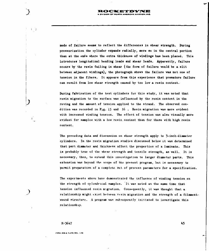
mode of failure seems to reflect the differences in shear strength. During
pressurization the cylinder expands radially, more so in the central portion
than at the ends where the extra thickness of windings has been placed. This
introduces longitudinal bending loads and shear loads. Apparently, failure
occurs by the resin failing in shear (the form of failure would be a slit
between adjacent windings); the photograph shows the failure was not one of
tension in the fibers. It appears from this experience that premature failure
can result from low shear strength caused by too low a resin content.
During fabrication of the test cylinders for this study, it was noted that
resin migration to the surface was influenced by the resin content in the
roving and the amount of tension applied to the strand. The observed con-
dition was recorded in Fig. 15 and 16 . Resin migration was more evident
with increased winding tension. The effect of tension was also visually more
evident for samples with a low resin content than for those with high resin
content.
The preceding data and discussion on shear strength apply to 3-inch-diameter
cylinders. In the resin migration studies discussed below it was determined
that part diameter and thickness affect the properties of a laminate. This
is probably true of the shear strength and tensile strength, as well. It is
necessary, then, to extend this investigation to larger diameter parts. This
extension was beyond the scope of tku- present program, but is necessary to
permit preparation of a complete. Set of process parameters for a specification.
The experiments alove have demonstrated the influence of winding tension on
the strength of cylindrical samples. 10 , Iwas noted at the same time that
tension influenced resin mi.gration. Consequently, it was thought that a
relationship might ( xist between resin migration and the strength of a filament-
wound structure. A program was subsequ.ently initiated to investigate this
re lationship.
R-3647 45
FORM 101,1 PLATE REV. 1,58

Ml. I-ON OF NOR IH AMERICAN 'VIAT ON INC
Figure 15. Cylindrical Samples Showing the Effect
of Winding Tension on Resin Migration
(13 'to 17 percent resin)
46 R1-3647

A OIVIRION OF NORTH AMERICAN AVIATION INC
6-Pound Tension 24-Pound Tension
16 to 20 Percent Resin
Figure Cylindrical Samples Showing the Effectof Winding Tension on Resin Migration(16 to 20 percent resin)
R-3647 47
A DIVISION OP NOWTH AMEN|KICAN AVIATION. iNO.
()
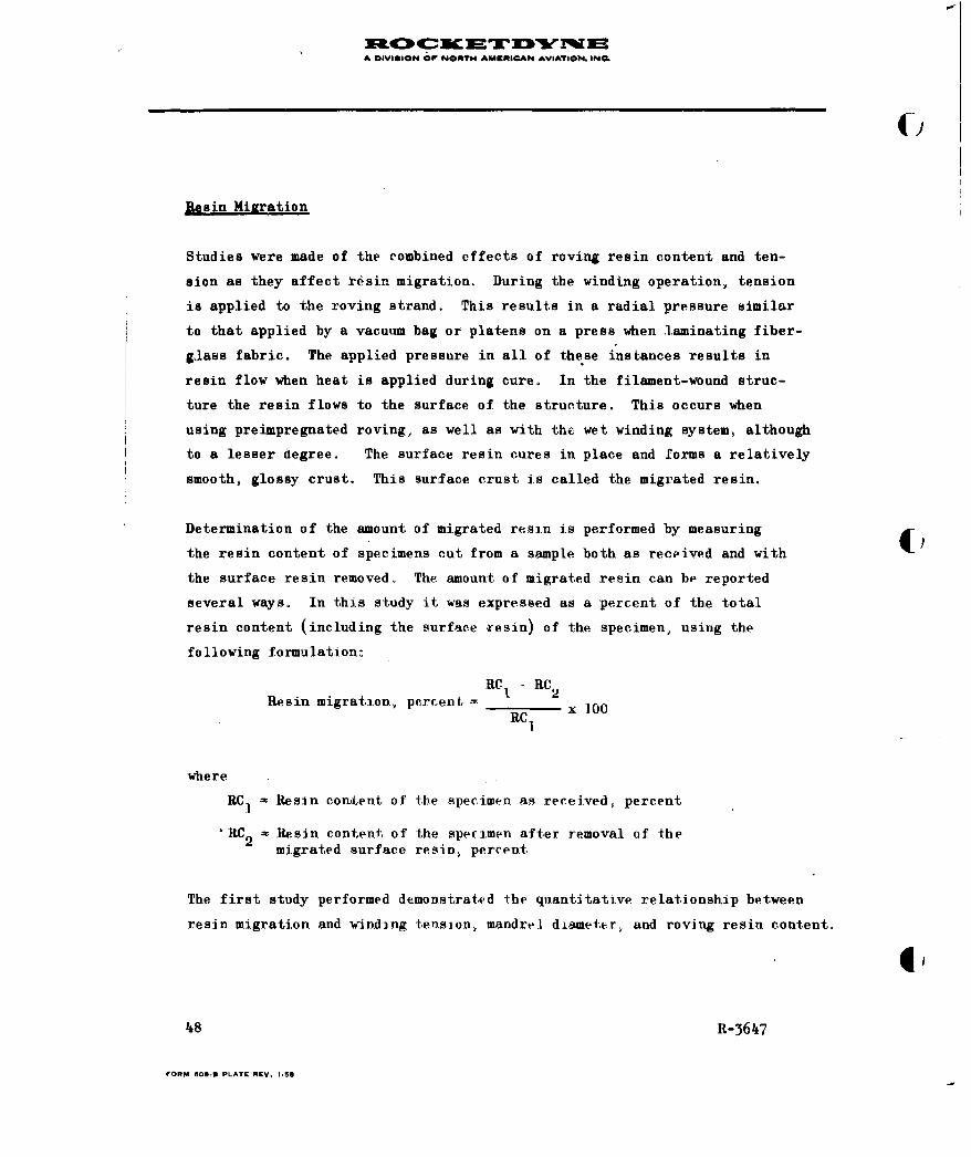
Resin Miaration
Studies were made of the combined effects of roving resin content and ten-
sion as they affect resin migration. During the winding operation, tension
is applied to the roving strand. This results in a radial pressure similar
to that applied by a vacuum bag or platens on a press when laminating fiber-
glass fabric. The applied pressure in all of these instances results in
resin flow when heat is applied during cure. In the filament-wound struc-
ture the resin flows to the surface of the structure. This occurs when
using preimpregnated roving, as well as with the wet winding system, although
to a lesser degree. The surface resin cures in place and forms a relatively
smooth, glossy crust. This surface crust is called the migrated resin.
Determination of the amount of migrated resin is performed by measuring
the resin content of specimens cut from a sample both as received and with
the surface resin removed. The amount of migrated resin can be reported
several ways. In this study it was expressed as a percent of the total
resin content (including the surface resin) of the specimen, using the
following formulation-
RC 1 -RC 2
Resin migration, percent =, RCI 2x 00RC1,
where
RCI = Resin condent of the specimen as received, percent
'RC 2 Resin conten, of the specimen after removal of themigrated surface resin, percent
The first study performed demonstrated the quantitative relationship between
resin migration and winding tension, mandrel diameter, and roving resin content.
48 R-3647
FORM 6OO3 PLATE REV. 1.5S
A DIIION OF NONTH AMKgIRCAN AVIAION. ING.
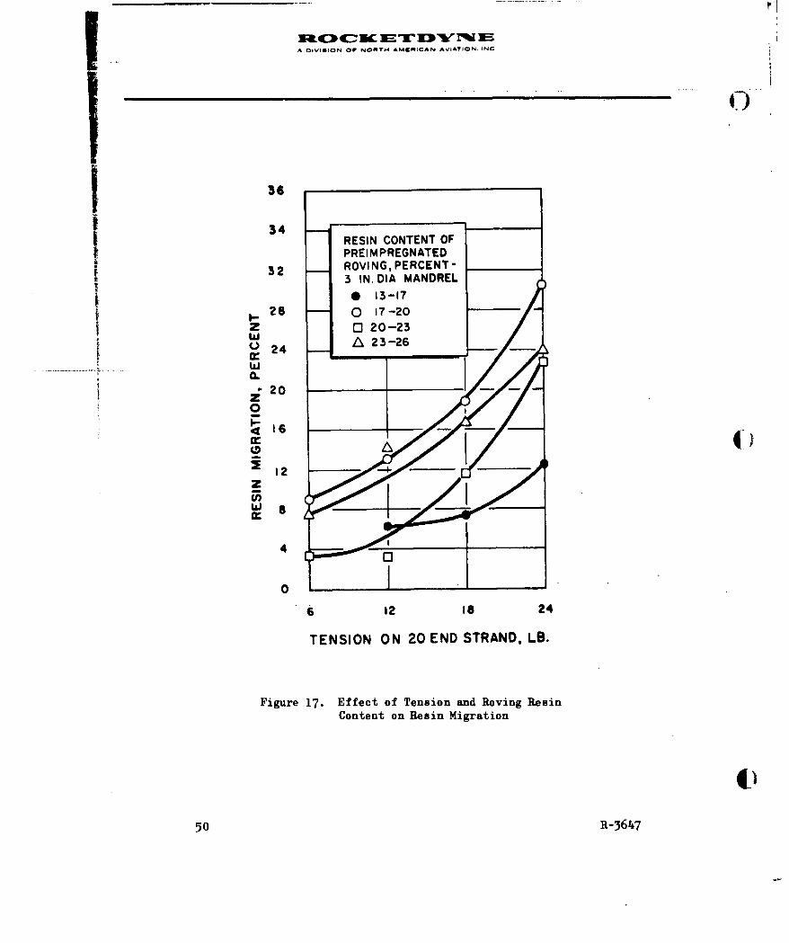
In this study, winding was performed on 3-, 8-, and 13-inch-diameter
mandrels at 12, 18, and 24 pounds of tension, using roving having ap-
proximately 19 and 24 percent resin content. These samples consisted
of circumferential windings only applied to a thickness of 0.06 inch.
In addition, winding was performed on 3-inch-diameter mandrels at 6,
12, 18 and 24 poundsof tension, using roving having four different
resin contents. These samples were standard 3-inch-diameter cylinders
with a 0.065 inch-thick wall and a layer of fabric in the wall as
described in the Appendix. The results of this study are shown graph-
ically in Fig. 17,
Resin migration increased sharply with strand winding tension in the
rAnge from 6 to 24 pounds, Resin migration was greater in the 23 to
26 percent resin content range than in the 20 to 23 percent and 13 to
17 percent range, but less than in the 17 to 20 percent range. This
appears to be inconsistent. However, the factor of flow, as affected
by resin advancement, is probably having an influence on the resin
migration. The study of resin flow was not included in this program,
but certainly should be in future work.
The influence of part diameter on resin migration is shown in Fig. 18.
Resin migration decreases rapidly as the diameter is increased. This
is to be expected since the radial load or squeezing pressure of the
tension applied to the strand is a function of the diameter of the
mandrel and the amount of tension applied.
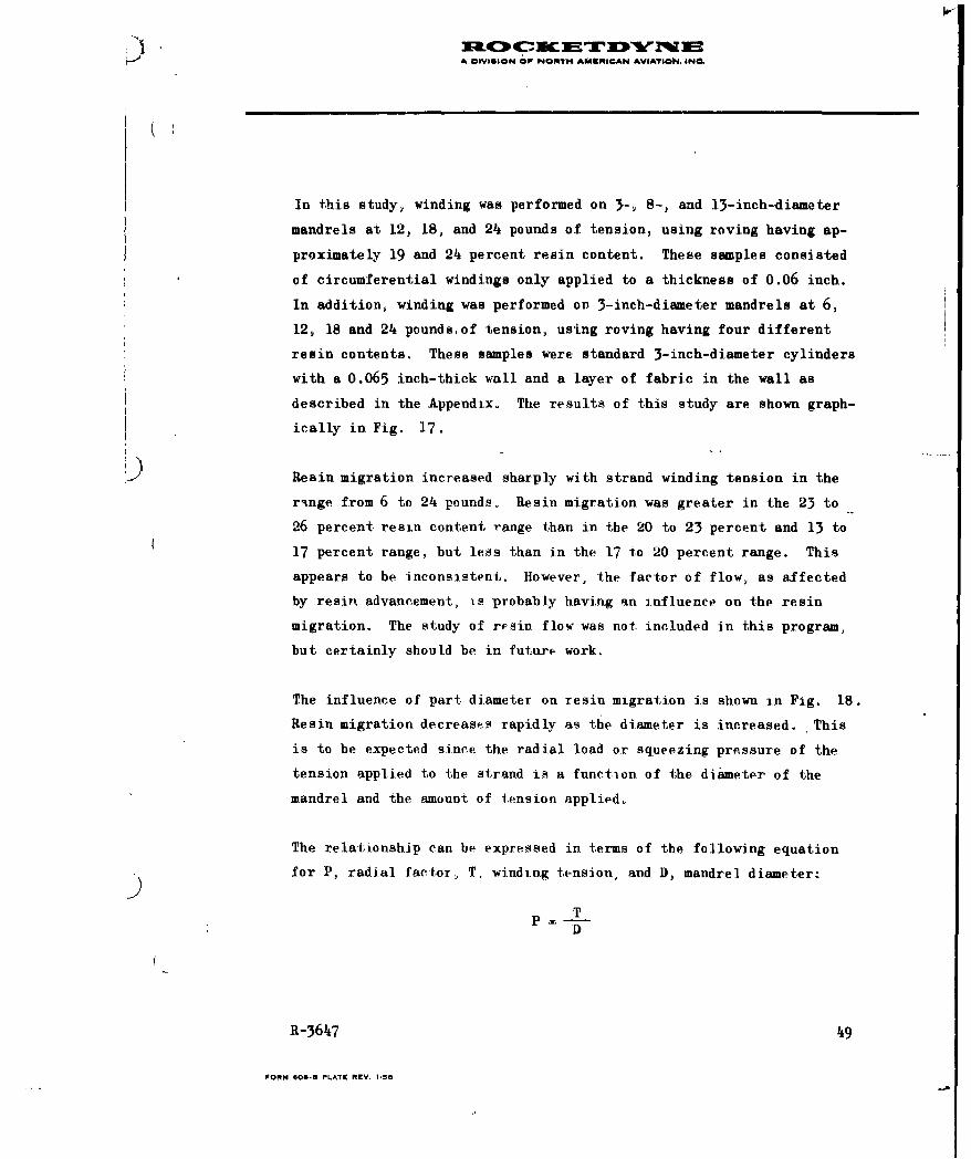
The relationship can be expressed in terms of the following equation
for P, radial factor, T, winding tension, and D, mandrel diameter.
TD
R-3647 49
FORM 00-B PLATE REV. 1-50
A DIVgION OF NORTH. AMERICAN AVIATION. INC
34 - _ _ _ _ _ _ _
RESIN CONTENT OFPREIMPREGNATED
32 ROVING, PERCENT-3 IN. DIA MANDREL0 13-17
28 0 17-20Z 0 20-23
'24A236
0
-2
A (I
Lu. a
4
00
6 L2IS2
TENSION ON 20 END STRAND, LB.
Figure 17. Effect of Tension and Roving ResinContent on Resin Migration
50 R-364~7

f A iVIGION OF NORTH AIVIRICAN AVIATION INC
36 RESIN CONTENT INPREIMPREGNATED ROVING-I MANDREL DIAMETERS17-20 PERCENT 23-26 PERCENT
34 -0 3 IN. -0 3 IN.-08 IN. -- 0 8IN.-A3 IN. -613 IN.
32 - - _ _ _ _ _ _ _ _ _ _ _ _
zwA 28
w0.24
z0
~20
zra 2w
4
012 IS24
TENSION ON 20 END STRAND, LB.
Figure 18. Effect of Mandrel Diameter andRoving Tension on Resin Migration
R-361i7 51

A OIVISION O NONT04 ANUNICAN AVIATION. INC.
Since resin migration is dependent upon both tension and diameter, it
seems logical to correlate it to the load factor, P. This has been done
in Fig. 19 , using the data from Fig. 18 . The load factor, P, for each
tension and diameter is given in the chart below.
T 12 12 12 18 18 18 24 24 24
D 13 8 3 13 8 3 13 6 3
P T 0.92 1.5 4 1.38 2.5 6 1.85 3 8
It is evident in Fig. 19 that the resin migration and P relationship is
practically a straight line. Deviations are probably caused by variations
in the construction of the 'amples such as use of the fabric interply and
variations in the resin content in the preimpregnated roving.
In another phase of this study, the effects of resin migration on the
strength of filament-wound cylindrical samples was investigated. This
was done by relating hoop tensile stress to resin content in the inner
and outer layers of the samples. Thin-walled and thick-walled samples
were fabricated. To prevent premature failure of cylindrical specimens
during hydrostatic test, a layer of longitudinal filaments is placed in
the center of the thickness of the wall. In the thin-walled (0.06^ inch)
samples (the same samples that were used in the first study)*, a pre-
impregnated fiberglass unidirectional fabric was used. This fabric had
a resin content of approximately 20 to 22 percent which in some instances
differed from the resin content of the preimpregnated roving used to wind
* This is the standard 3-inch-diameter cylinder described in the Appendixfor use in the hydrostat c buist test.
52 R-3647
FORM 60.- PLATE REV. 1.$8
A DIVISION OF NORTH 4AMCMiCAN AVIATION. INC
RESIN CONTENT IN PREIMPREGNATED32 ROVIN_ __ _ _ __ _ _ _
32 MANDREL DIAMETERS17 TO020 PERCENT, 23 TO 26 PERCENT
o 3 IN. 0 3 IN.
o 8 IN. U 8 IN.24 li311 131N. nr
0
z
Cr 8
0 A -
0 2 4 6 8 10RADIAL LOAD FACTOR P=T/D
Figure 19. Effect of Radial Load on Resin Migration
R-364i7 53

A DIVISION OF NORTH AMSftICAN AVIATION. IN0.
the samples. This caused the resin content percentage in some of the
cured samples to be greater than in the roving, and in some of the cured
samples to be less than in the roving. An, adverse effect on the pattern
of resin migration probably took plaee. Also, since the fabric was im-
pregnated at a different time than the rcving, it is expected that the
resin in the fabric had a different flow characteristic. This also might
have had an adverse effect on the pattern of resin migration.
To overcome these difficulties on the thick-walded (0.125-inch) samples,
the same preimpregnated roving that was used for the c ircumferential
wrapping was used for the long.tudinal filaments. This was donw by
wrapping the preimpregnated roving on a flat plate to form a flat sheet
of unidirectional fibers, A slight amount of heat was applied with an
iron to make the resin sticky and to consolidate the roving into a sheet. ()The sheet was cut into smaller size pieces for placement in the filament-
wound samples. These cylinders were constructed to simulate the construc-
tion of a pressure vessel That is, the ratio of circumferential fibers
to longitudinal filaments was two to one. Resin content was measured
on the preimpregnated roving used for the rircumferential windings and
that used for the longitudinal filaments. The resin rontent was measured
on the total wall, thickness of tbe cylinders and on the inner and outer
layers. Each sample cylinder was tested hydrostatically and the hoop
tensile stress was calculated. These data are presented in Table 2.
On a similar set of thin-walled cylinders (0.070 nominat), the resin
-content was measured on the inner and outer wall. Resin migration was
calculated for the thin-walled and thinth-walled samples . In ,he case of
the thin-.walled samples, migration was ,:aloulated as follows:
Resin Cent-ent Resin Cortintin Outer Layp-r in Inner LayerResin Migration -R_.sin Cotn i TtlalTbcne X 1,00 (1)Rfsin Gontcnt, iR Total. Wall Tbi.c-ne6,7s
54 R-3647

TrAlE 2
DATA ON RESIN CONTENT AND HOOP TENSUEIE STRENG1
FOR MiGxrTION STUDIES OF THICK-WALLED
3- INGH-DIAMETER CYLINDERS
Circumferential Longitudinal Total Roving Sample TeSpecimen Roving Resin Roving Resin Resin Content, Tension, Resin Coni
No. Content, percent Content, percent percent pounds percent
Low ResinContent
568 21.2 20.3 21.0 12 21.1
569 20.7 20.3 20.6 12 18.6
570 19.4 20.6 19.8 12 18.4
571, 21.1 '20.6 20.9 18 16.1
572 20.9 2.0 20.8 18 18."
573 20.8 21 20.8 18 18.3
57h 20.8 21 20.8 24 18.3
575 20.5 21.15 20.9 24 19.9
576 21.1 21.5 21.2 24 18.2
High ResinCon tent
577 21.9 25 22,.9 12 22 ,
578 21.8 25 22.9 12 22.6
579 26,.5 23,7 25.6 12 21.8
580 23-2 23.7 23.3 18 21,6
581 22.2 23°1 22-5 18 20,1
582 22.1 23.1 22,4 18 21A
5 ,) o8 ).. 1 ,, It 24 19. 'I
54271,1 22,7 2506 011 22.S
585 276 22.4 25.9 21 122
RI-36'7 'Surface resin removed,.

A OIVII66 OF NONTH AUENICAN AVIATON. eoe.
TABLE 2
ESIN CONTENT ANI) HOOP TENSILE STRENGTH
MIGRATION STUDIES OF THICK-WALLED
3- INCH-DIAMETER CYLINDERS
al Roving Sample Total Outer Layer Inner Layer Ultimate Hoop4 Content, Tension, Resin Content, Resin Content, Resin Content, Tensile Strength,ercent pounds percent* percent* percent psi
21.0 12 21.1 19.7 15.6 247,000
20.6 12 18.6 20.1 15.8 246.000
19.8 12 18.4 20.6 14.8 244,000
20.9 18 16.1 16.5 15.0 239,000
20.8 18 18.6 19.8 14.9 240,000
20.8 18 18.3 20.6 16.2 252,000
20.8 24 18.3 22.5 14.3 249,000
20.9 24 19.9 21.8 14,0 2-55,000
21.2 24e 18.2 20.8 16.2 248,000
22.9 12 22.0 21. I 18 5 215,000
22.9 12 22.6 20.6 18,8 221,000
25.6 12 21.8 21 , 17."h 237,000
23.3 18 21,6 22.1 10,0 218,000
22.5 18 20,5 21.2 15.5 212,000
22. It 18 21.2 21,8 t56( 226,000
21. t, 24 19, ' 19,o5 18,11 238,000
25.6 24 22.9 25.5 171 200,000
S25.9 24 22.8 21,. o 1-7.2 21 3000
A DIVISION OP NOATH AMERICAN AVIATION. IN.
)
Resin content in the outer layer was measured, with the migrated surface
resin removed. Resin migration was calculated with two methods for the
thick-walled cylinders. One procedure was as above, the other was as
follows:
Resin Content Resin ContentResin Migration = in Roving in Total Wall
Resin Content in Rbving x 100, (
The resin content in the total wall of the cylinder was measured, with the
migrated surface resin removed. The roving resin content was determined on
the roving used for longitudinal and on that used for circumferential fila-
ments. Since one-third Pf the sample was made of longitudinal fibers and
two-thirds circumferential, the total resin content was determined as
follows:
1/3 Resin Content (longitudinals) + 2/3 Resin Content (circumferentials)
= Total Resin Content of Roving Used to Make Sample
The resin migration data for -the thick-walled and thin-walled cylinders are
presented in Table 3 and 4 , respectively.
56 R-3647

A DIVISION OP NORY AMERICAN AVIATION. INC.
TABLE 3
RELATIONSHIP OF TENSION AND ROVING RESIN CONTENT TO
RESIN MIGRATION, 3-INCH-DIAMETER THIN-WALLED
-," (0.060-INCH-THICK) CYLINDERS
Resin Content ResinSpecimen In Roving, Tension, Content**, Migration*, Hoop Tensile
No. percent pounds percent percent Strength, psi
514 17 to 20 6 18.2 10.4 253
517 17 to 20 12 16.4 7.3 260
520 17 to 20 18 15.4 7.2 251
K 524 17 to 20 24 14.6 14.4 236
509 13 to 17 18 16.2 6.2 260
532 20 to 23 18 19.9 19.6 251
545 23 to 26 18 18.8 11.2 216
* Resin Content Resin Content
Outer Layer Inner Layer (Eq. 1 on p. 54)Resin Content Total Wall
** Total wall, surface resin removed
'.
R-3647 57
FORM 600- PLATE REV. 1.50
944
~j ~ inr-4 40 L;c
r- ooc.44 eq P - f
C ~ c IN ~ i' ~
E-40au $I 4 4-
E.4l
14 00 14
.4-4
_ _ -4 C1e4'3t
A o-0 ID-
1414~C -H E~ 1 -4
- E-
-q~~~~0@ 1. 0', 4C1PI : w
P64 Z 0 - - 4
E- to to ho0
0 u
teN P4 +20
1 .4 .44 -4 L -4
-4 n 0' 4 N Ck
o 0
FOR 00- ET E.15*A
A DIVIUION Or NORTH AMERICAN AVIATION. INL
Some of the values of migration in Table 4 are not included in the
average value presented. This has been done because examination of the
data in Table 2 for the specimen involved indicates that the data are
not reliable. An example involves the value of migration calculated
using Eq. 2 for specimen 568. In using the data from Table 2 , the
resin migration value would be 0 and out of line with values determined
for specimens 569 and 570. This happens because the resin content in
the cured sample (taken with the migrated surface resin removed) is the
same as the value for resin content in the roving used. This seems in-
congruous since if the migrated surface resiu had been properly removed,
the resin content in the sample then must of necessity be lower than
)that in the roving used. The specimen therefore is assumed to have been
improperly treated and the value obtained inaccurate, and it should
not be included with the others in the series.
It is apparent with both the thick- and thin-walled cylinders that the
resin migrates to the surface. This reduces the resin content in the
inner layers and increases the resin content in the outer layers (even
when the excess surface resin has been removed). It is possible for the
outer layers to take on resin so that the resulting content, by percent,
is greater than the percentage in the preimpregnated roving used to
fabricate the sample. It is also noted that the values of migration for
the thick-walled cylinders are greater than for the thin-walled cylinders.
This is to be expected since a greater radial pressure is built up in a
thick wall than in a thin wall.
In the thick-walled samples, it is apparent that the migration of resin
from the inner layers to the outer layers increases as the tension on the
roving strand is increased. Although there can be a significant difference
in resin content between the inner and outer layers, only a relatively low
R-3647 59
FORM 608-8 PLATE REV. I 58
A cIVivION OP NOTrH AERISCAN AVIATION. IN6
percentage of the total resin content is squeezed to the surface. This
is indicated by the lower values for migration calculated by Eq. 2 than
those calculated by Eq. 1.
The data in Table 4 indicate that the resin migration does not increase
with resin content in the roving, but actually decreases on a percentage
basis. This would indicate that the amount of resin which migrates to
the surface is constant, and consequently the percentage is less for
higher resin content roving. Resin migration occurs because the tension
in the roving creates a radial pressure, analogous to applying a vacuum
bag over the laminate, which squeezes the resin to the surface. This
is enhanced during cure when the resin softens from the heat and flows
before gellation occurs. The flow of resin allows relaxation of the
tension in the roving which reduces the radial pressure and the tendency
for additional migration. The migration limit appears to depend not on 4the resin content but on the radial pressure available.
The relationship between resin migration and hoop tensile stress is not
evident in the thin-walled cylinders, nor is the pattern of inner- to-
outer-layer migration relative to tension or roving resin content as
evident as in the thick-walled cylinders. The relationships are probably
clouded by the use of the layer of preimpregnated fabric, as discussed in
detail above.
The relationship between resin migration and tensile strength in the
thick-walled cylinders is not clearly evident. It may be clouded by
the variations and inconsistencies in the construction of the samples.
Preimpregnated roving was used for the longitudinals in order to have
a material of the same resin content and flow characteristic as in the
circumferential windings. Although material for the longitudinals was
60 R-3647
FORM 6- PLATE REV. 1.50
A DIVIGION O NORT0 AK4M6ICAN AVIATION. INC.
from the same batch as that used on the circumferential windings, it was
not possible to match the resin content. The manufacturer's tolerance on
the resin content of the preimpregnated roving is plus or minus 2 percent.
In the range selected for samples 577 to 585 (Table 2 ) this allows a
variation from 22 to 26. Actual measurements ranged from 20.8 to 27.6
percent. This variation was not predicted; consequently, material having
a wide range of resin content inadvertently was used in some samples.
Fxamples are samples 577 and 578 where the resin content in the longi-
tudinals is 25 percent compared to slightly less than 22 percent for the
resin content in the roving for the circumferential windings. This
accounts for the peculiar situation with these samples where the percent
resin content in the total wall of the cured sample is greater than the
percent content in the outer layer (migrated surface resin removed in
both instances).
An examination of the data in Table 2 reiterates the relationship of
resin content, both in the preimpregnated roving and in the cured sample,
to hoop tensile strength described earlier in the report. The average
strength of specimens 568 to 576 is higher than the average strength of
specimens 577 to 585. The resin content values are in inverse ratio, as
expected.
Another example of this phenomenon is illustrated by specimen 583. This
specimen was made as a part of the group, numbers 583,584 and 585, wound
with 24 pounds of tension, using high-resin-content roving. This specimen
has the highest tensile strength of the three specimens and, in fact,
of many of the specimens included in the group from 577 to 585 made with
high-resin-content roving. At the same time, the roving resin content of
21.4 percent and the sample resin content of 19.4 percent are the lowest
R-3647 61
FORM 606-U PLATE REV. 1.58

A DIVISION OP NOAT0M AUURICAN AVIATION. ING.
of any specimen in the high-resin-content group,"'
The specimen also seems out of place as indicated by the resin migration
value of 5.7 percent, calculated by Eq. 1. This value compares to 36.7
and 31.5 for specimens 584 and 585, respectively. Because it yas so
badly out of line, it was left out of Table 4 . The roving resin content
and sample resin content values of 21.4 and 19.4 percent for specimen
583 would indicate that this specimen actually belongs in the 568 to
576 group. Because it was wound at 24 pounds tension, it should fit in
with specimens 574, 575 and 576. However, the inner- to outer-layer
resin migration value of 5.7 percent (calculated using Eq. 1) does not
match with the 35.3 percent average value for specimens 574 through 576.
This same situation existed when 583 was compared with 584 and 585.
The discrepancy involved would seem to reflect a difference in resin
flow in the materials used. 4)
Resin flow is a significant property of preimpregnated roving which in-
fluences resin migration. In this respect it also influences strength
properties. This is probably more significant in larger diameter filament-
wound structures than in 3-inch-diameter cylinders. The influence of
resin flow was not included in this program but warrants study, along
with additional investigation of resin migration.
Tackiness and Volatile Content
The purpose of this study was to determine the relationship of tackiness
in the preimpregnated roving to volatile content, resin content, processing
parameters, and properties of the cured laminate. The first step in the
investigation was to develop a suitable test for measuring tackiness.
62 R-3647
FORM 600-B PLATE REV. 1-58

I A DiVISION OP NONITh AM9#1@AP4 AVIATIO. INC.
Several different procedures were studied for evaluating tackiness in
preimpregnated roving. One method measured the tackiness of roving by
allowing a steel cylinder to roll down an inclined ramp along two parallel
strands of roving spaced apart on a horizontal surface. Tackiness was
measured in terms of the distance the roller moved along the strands of
roving i.e., the greater the tackiness, the more the motion of the roller
was impeded and the shorter the distance it rolled before coming to rest.
The test procedure was found to have a number of serious flaws. High
spots or slight twists in the roving prevented the roller from making
complete contact with the tacky surface of the strand. Because of this
factor, it was difficult to obtain reproducible test results. In addi-
tion, it was intended that roving strands of various widths (20 ends,
60 ends, etc.) would have to be tested. Each width would impose a dif-
ferent set of test conditions because of the variation in areas involved.
For these reasons, tackiness testing by this method was not continued.
In another test, strands of preimpregnated roving, 12 in. long, were
placed on a chrome metal mirror plate and heated for 10 minutes in an
oven at 20 F. The strands were then pressed firmly against the polished
metal surface by five passes of a 2-pound roller. The plate was placed
at a 45-degree angle, and the time in seconds required to peel a 10-inch
length of strand from the plate by the pull of a 100-gram weight was
taken by stopwatch. This test gave consistent and reproducible results
for several lots of roving. However, several other lots of roving strands
failed to adhere to the surface of the metal plate. This result may be
due to resin advancement.
R-3647 63
FORM OB-f PLATE REV. 1.50
A OSVS@N iC ' OP N@IPP4 &UKNICAN AVIATION INS
In another method, the time required to peel a 2-inch length of strand from
the surface of a spool of roving by the pull of a 100-gram weight was taken
by stopwatch. The time required was the measure of tackiness. This method
gave consistent results for most lots of roving, although the tendency of
individual filaments to detach from the roving strand affected the rate of
peel in a number of cases.
In still another method, the tackiness tester consisted of a flexible band
of steel 20-inches long by 3/8-inch wide by 0.015-inch thick. The band
was placed over a horizontal spool of roving in the spool box of a winding
machine. A weight of 2 kilograms was hung on one end of the steel strap;
the other end of the strap was connected to a spring balance. As the spool
of roving turned at a constant 'ate, the strip of steel dcted as a brake
band, and the pull of the band against the surface of the roving spool was
registered on the spring balance. This, in effect, was a measure of the
frictien factor of the. roving surface which was related, to its tackiness.
This method appeared to work fairly well, although more tests are needed
to complete the evaluation.
The method that was selected is described below. The equipment
consists of an inclined ramp and horizontal track as shown in Fig. 20
and 2L The ramp, inclined at 10 degrees, is approximately 18 inches
long. The track is 60 inches long. Both are made of V-shaped aluminum
extrusion. The strands of roving are placed on the track about 3/8 inch
from the point of the V and stretched tightly along the track by weights
(4 pounds for each 20 end in each strand). A 3/4-inch-diameter steel ball
is placed at a specified height on the ramp and allowed to roll down the
ramp and along the track in contact with the roving. The distance the
ball travels along the track is the measure of tackiness. The nature of
the test is such that a low number indicates more tack than a higher number.
64 R-3647
PORM BO-8 PLATR RCV. I-8

A rOlVIUION OF NORTH4 APMRICAN AVIATION INC
1 0.750 DIA STEEL BALL
/,,--OVNGSTRAND
SECTION AA
RAMP
RROVING STRAND
A ANCHOR SCREW
Figure 20. Tackiness Tester for Preimpregnated Roving
R-364i7 65

IR 0)4- 1C E-r " Iu 1WzA DIVI.,ION OF NORTH AMFERICAN AVIATION INC.
E-4I
0.4
66 R-364
A DIVISION OP NORm AMIC[AN AVIAIoN. INC.
S
Measurements were made on a selected group of spools of preimpregnated roving
to establish a base for comparison. These spools were fresh material (stored
at deep-freeze temperature since the day of manufacture). Table 5 gives results.
The first digit of the value of tackiness is the distance along the ramp the
ball rolled. The second number is the distance along the track and is the
average of five rolls. The values reported in Table 5 are listed in order
of decreasing tackiness, from left to right. The differences reported were
readily detected by "finger feel" and are in agreement with this subjective
test.
TABLE 5
TACKINESS TEST VALUES
J Spool No. 8 10 24 28 35 44 46
Tackiness 8-27 8-28.5 8-29 8-31 8-32 8-35 8-36Value
Temperature, 84 84 85 81 84 82 84F
The procedure used for the tests above and all subsequent tests consisted of
rolling the ball six times over each set of specimens. The ball was cleaned
with solvent before each pass. The average value of the distance traveled
for the last five passes is reported. In this test it was found that the
ball would iron out irregularities in the strand of fresh material on the
first pass over the roving, then, on the second pass, travel considerably
farther along the track. The ball rolls a greater distance each time on
subsequent passes, but the increments are progressively smaller. This is
why zero-in roll is used.
4
R-3647 67
FORM 60.-8 PLATE REV. 1.58
A DIVIION OP NORTN AMNSiOAN AViATiON. INC.
In another experiment, an attempt was made to relate storage of preimpreg-
nated roving at room temperature to change in tackiness and volatile content.
Samples of roving were removed from the outside of the spool each day, and
measurements of each property made. In essence, measurements were made on
surface material only. An analysis of Fig. 22 shows that the volatile con-
tent drops, but no trend of tackiness is discernible by this tackiness test
method, although reduction in tackiness is discernible by feeling the roving.
The erratic results indicated in Fig. 22 may be accounted for by the explanation
that as the roving ages it becomes hard and rigid. Small wrinkles are not
relieved when the roving is placed on the track and tension is applied by
the 4-pound weights. These wrinkles retard the travel of the steel ball,
especially near the end of its roll along the track. The older the preim-
pregnated roving is, the greater this influence which could account for the
apparent reversal of measured tackiness value.
Experiments have shown that the test is useful only on fresh or soft, pliable
roving which has a degree of tackiness that can be felt when the roving is
gently squeezed between the fingers. This was indicated by the tackiness
values determined on the material used in the tension and resin content study
which was reported in Table 6 , along with resin content, volatile content,
and manufacturers' lot number of preimpregnated roving. The values correlate
well with the finger-feel test and have a fairly narrow spread within each
lot. However, no relationship with volatile content or resin content is
discernible.
The nature of the tackiness test is such that the measurement range may be
extended in.either direction, low or high tackiness, by the distance the
ball is allowed to roll down the inclined plane. This is comparable to
changing scales by changing weights on a Rockwell hardness test . However,
the distance most often used is 8 inches up the inclined ramp.
68 R-3647
FORM 6008B PLATE REV. 1.58

A DIV4ION OF NOP1*W A16CUICAN AVIATION. INC
6-55_____
6-5C0____ ____I 0 TEST NO.2I
z 6-45
00S6-40
I.- 0 2o 6-35-0
w 0
,~6-30
-25
z 0___ T_ _ _ii EST NO.2ICr 1.8w
CL
z 1.40
w
4 1.0>-T
-
.02 4 6 8 10 12
STORAGE TIME AT ROOM TEMP (78 F) , DAYS
Figure 22. Effect of Aging on Tackiness and Volatile Content
R-3647 69
A DIVISION OP NORTH AMARICAN AVIATION. INC
TAKLE 6
PROPERTY DATA OF ROVING USED FOR TENSION
AND RESIN CONTENT STUDY
SampleTakenFrom Volatile Resin Tackiness
Spool Specimen Content, Content, TestNo. No. percent percent Value
696-2 501 1.43 13.7 8-45.4696-2 502 2.74 14.8 8-42.0696-2 503 2.76 15.3 8-38.9696-3 505 1.68 16.2 ....696-4 508 1.68 16.9 ....696-10 511 1.67 17.4 ....
646-48 513 1.87 18.3 8-37.7646-48 514 1.90 18.4 8-35.0646-48 515 1.68 19.6 8-34.2 4646-53 520 1.90 18.9 8-31.0
690-2 525 2.04 21.0 8-42.6690-2 528 1.85 22.4 8-49.4690-3 529 1.66 22.4 8-39.0690-3 530 1.70 19.6 8-'37.2690-4 532 1.39 24.6690-7 534 2.56 22.2 8-50.7
589-1 537 1.57 24.2 8-27.7589-1 539 1.55 25.0 8-20.9589-2 541 1.31 25.2 8-21.9589-2 544 1.43 24.0 8-28.1589-3 546 1.52 25.4 8-28.3
7)70 R-36I 7

A DIVISION OP NORTH AHURIcANAViarION, iN.
The temperature at which the test is performed is significant. Measurements
reported in this paper were made at 75 to 78 F. The tackiness of the roving
will increase with temperature. A very interesting observation made during
development of this test was that materials which had significantly different
values of tackiness at 77 Fhad practically the same value of tackiness at 12 F.
The next step, with the tackiness test method developed, was to relate the
tackiness of preimpregnated roving to process parameters.
For this purpose, a study was undertaken t. determine the influence of pre-
impregnated roving tackiness on the ability to wind an unstable pattern.
The work was performed on a mandrel which measured 18 inches in diameter by
24 inches long. The pattern chosen was a low-angle helical or pole-to-pole
pattern at an angle of 20 degrees to the longitudinal axis. The winding was
performed, using a single strand of 20-end preimpregnated roving of the same
type used throughout the program. The pattern of application to the mandrel
was sequential, with each strand spaced equally, parallel to the preceding
strand, and spaced with approximately a 30-percent overlap.
Trial windings of the roving were placed parallel to each other on the mandrel,
with a progressively increasing polar diameter of the wrap at one end and de-
creasing diameter at the other end. The winding angle for the cylindrical
portion was kept at 20 degrees to the axis (Fig. 23 ). When the polar dia-
meters at each end of the winding were equal, the tiameter was 8. inches
at each end. Tests for slippage were made by increasing the diameter at the
top of the mandrel by 2A-inch inerem ents until slippage occurred.
)These tests were made using preimpregnated roving of two levels of tackiness,
as measured on the rolling ball tackiness tester. The low-tack spool, No. 696-8,
had a tack value of 8- > 60> The high-tack spool No. 646-57, had a tack
R -367 TV1 71
FORM 608-0 PLATE REV. I."8
A DIVISION OF NORTI4 AIERICAN AVIATION. INC
POLAR OPENING
8.4 INCH DIAMETERPOLAR OPENING
TESTWINDING
DIRECTION[IN WHICH
20 ROVINGDGIS WOUND 4
{ DRECTION OFMANDREL ROTATION
8.4 INCH DIAMETER
18 INCH DIAMETER
Figure 23. Windinj"Pattern for Study of the Ef fectof Preimpregnated Roving Tackiness onthe Ability to WinO an Unmtable Pattern
72 R-361i7

A DIVIDION OP NORTH AMURICAN AVIATIOW. INC.
value of 8- 32.4. To convey some meanings to these tackiness values, the
low value (high-tack) material is slightly sticky to the touch when squeezed
between the fingers, and the high value (low-tack) material is very "dry" to
the touch.
The first part of the investigation consisted of performing the slip test
winding on a bare mandrel. This mandrel was made of plaster, sealed with
a cellulose acetate plastic film and coated with a nonslippery wax mold
release. A few ,Taps of the low-tack preimpregnated roving were wound on
Lhe mandrel. If no slip occurred, these wraps ,iere removed from the mandrel
N and another wrap was made at a larger polar diameter at the top (smaller
at the bottom), This procedure was continued until slip occurred.
The position on the mandrel where this happexd is shown in Fig. 24 . A
zlight amount of slip was considered to have occurred when the strand being
applied moved out of position after contacting the mandrel to increase the
spacing relative to the adjacent strand, this occurred on the bare mandrel
at a polar diamett, at the top of 9.6 inches. Severe slip was considered
to have occurred when the wr pping slipped comp-'t4ely off the mandrel. With
low-tack roving used, this occurred at a polar diameter of 12 inches,
When slipping occurred with the low-tack material, use of the high-tack
material was begun. The procedure described was followed until slip
occurred, Slight slipping oc-curred, with tbis material, at a polar diameter
of 14.4 inches, (Fig. 25 ).
For the second phase of this investigation, the mandrel was covered with a
"base wrap" of low-tack preimpregnated roving. This was applied as a pole-to
pole wrap to contact the polar bosses Trial windings of low-tack roving
were then placed over this base wrap in the same manner . application to
R-3647 73
FORM 606-B PLATE REV. .15
A DIVINION OFP N00TH AMERICAN AVIATION. INC
6930-2/8/62-23
Figure 21i Winding Low-Tack. Preimpregnated Roving on a Bare Mandrel
74 R-364i7

X&401 4r- sc RE IA ",k %ADIVISION OF NORTH AMCRICAN AVIATION. INC
SLP CCR
6930-2/8/62-2A
4, Figure 25. Winding High-Tack Preimpreguated Roving on a Bare Mandrel
R-364&7 75

A SIVIGiON OF NORT14 AMCRICAN AVIATION. INC.
4-)
the bare mandrel had been made. The experimental wrapping setup is
shown in Fig. 26.
When the low-tack material began to slip, the experiment was continued
with high-tack material over the base wrap. Upon completion the base
wrap of low-tack roving was removed, and a wrapping of high-tack preim-
pregnated roving applied. The slip experiments were repeated, using
both low- and high-tack roving. The polar diameter values at which
slipping occurred are given in Table 7.
The data in Table 7 indicate that there is almost the same tendency for
the strand to slip when wrapping on a base wrap of preimpregnated rov-
ing as when wrapping on the bare mandrel. This condition was not antic-
ipated. It was thought that there would be considerably more resistance
to slip when wrapping preimpregnated roving over roving because of the 4ipressure-sensitive cohesive action of the resin.
An explanation for the above experiments may be that since the roving
strands in the base wrap overlap, the wrap has a stepped, or rough,
surface condition. The test winding placed over this rough-surfaced
base wrap makes point contact with the high spots of the surface only
to provide a smaller area of contact than when applying roving to the
bare mandrel. Although there may be more stickiness in the roving to
roving contact, this is offset by the lower area of contact, resulting
in less resistance to slip than anticipated.
This study has shown conclusively that it is possible to wrap a more un-
stable pattern with high-tack preimpregnated roving than low-tack roving.
In addition, it has been shown that preimpregnated roving can be used to
wind a polar opening of nearly 70 percent of the case diameter, using a
76 R-3647
FORM 600.3 PLATE REV 1.56
A DIVIION OF NORTH AMERICAN AVIATION INC
- I
694o-2/20/62-2
Figure 26 Winding Preimpregnated Roving Over a Wrapof Preinipregnated Roving
R1-3647 77
A DIVISION OF NORTY"i AMEfICAN AVIATION INC
TABLE 7
THE INFLUENCE OF TACKINESS ON THE ABILITY TO
WIND AN UNSTABLE PATTERN
Polar Diameter of Test Winding on ABL" Mandrel,
Inches and Percent of Mandrel Diameter.
Low-Tack Roving,Tack Value 8- >60 High-Tack Roving, Tack Value 8- 32.4
Wind On Wind On Wind On Wind On Wind On Wind OnBare Low-Tack High-Tack Bare Low-Tack High-TackMandrel Wrap Wrap Mandrel Wrap Wrap
8.4 inches 8.4 inches47 percent 47 percentNo Slip No Slip
9.6 inches 9.6 inches 10.2 inches 9.6 inches53 percent 53 percent 57 percent 53 percentSlight Slip No Slip Slight Slip No Slip
12 inches 12 inches 12.6 inches 12 inches 12 inches 12.6 inches67 percent 67 percent 70 percent 67 percent 67 percel 70 percentSevere Slip Slip No Slip No Slip No SlipSlip
14.4 inches 14.4 inches 15.0 inches80 percent 80 percent 83 percent
_Slight Slip Slight Slip Slight Slip
*18-inch-diameter x 24 inches long. Test winding applied at constant
20-degree angle to longitudinal axis.
78 R-3647

A DIVIGION OP NORTH AMRICAN AVIATION. INM
nongeodesic or unstable pattern. This study also indicates the poten-
tial usefulness of the ability to quantitatively measure the tackiness
of preimpregnated roving.
It should be noted that the polar opening at which slip will occur is
dependent upon the end dome configuration and the length to diameter
ratio of the case. These factors must be considered when applying the
data in Table 7 to a specific example.
To illustrate: The data presented in Table 7 were collected using high-
and low-tack roving. On a bare mandrel and with low-tack roving, slight
slip occurred at a polar opening of 53 percent of the case diameter.
With high-tack roving, slight slip occurred at 80 percent of the case
diameter. Therefore, it can be assumed that medium-tack roving would
have slight slip at 60 to 70 percent.
Figure 23 shows that the roving was placed on the mandrel at a 20-degree
angle to the axis. Contrary to the description in Fig. 23, it will now
be assumed, in the example under consideration, that the polar wrap
openings are of equal diameter, that the openings are 60 percent of the
diameter and the roving is placed at a 20-degree angle. This results in
an effective length to diameter ratio for the case of 1.65. The calcu-
lation is shown in Fig. 27.
If roving of the same tackiness were used on a mandrel with a similar
end dome shape, but with a greater length to diameter ratio, and the rov-
ing was wound with a polar opening of 60 percent of the diameter, the
roving would be expected to slip. Although all other conditions are
constant, the greater length to diameter ratio has introduced a condi-
tion of greater instability. This was exemplified during fabrication
R-3647 79
FORM 6001 PLATE RFV 1-58
I A 04OIIN OFP4OTYN AM5UiCAN AVIATION INC
I TEST CASE (FIG. 23)
0.3 DIA.
DI A.
L/2
L'\C
THEORETICAL CASECONFIGURATION FOREFFECTIVE L/D RATIO
Tan 20 degrees 0 Dor Tan 20 degrees=0.D9L,2 L
the L = L - o.60.6 D - an 20 degrees he D-Tan 20 degrees
L 1.65
Figure 27. Calculation of Effective L/D Ratio forTackiness Study
80 R-365,7

A iVISION Or NORTH A.KIMICAN AViAION. INC
of a case on another program when a mandrel having a L/D = 1.87 was
wrapped with a polar opening of 60 percent of the diameter. Severe
slipping of the preimpregnated roving occurred. In this instance it
would have been possible, by using the above analysis, to predict the
slippage condition and specify remedial measures such as use of very
tacky roving.
Another example of the significance of tackiness was demonstrated dur-
ing checkout of the numerically tape-controlled winding machine. A
polar wrapping pattern was being applied to an 18-inch-diameter by
24-inch-long mandrel. The purpose was to check the accuracy of spacing
of the strand. To do this, a mercerized cotton thread was used (Fig.! 28
and 29). The spacing was not uniform over the end domes. It was
noticed that the thread would slip as it traversed the buildup section
. around the polar opening (Fig. 29). Each strand subsequently was taped
in place as it traversed the buildup area. With no slippage, the spac-
ing of the thread was uniform. In essence, use of the tape was the
same as creating tack on the thread to prevent it from slipping away
from the true laydown path.
The same situation occurred when preimpregnated roving was substituted
for the cotton thread. The initial tests were made with low-tack mate-
rial, and the strand spacing was irregular on the end domes for the
same reason as with the cotton thread. No slip occurred after switch-
ing to tacky roving, and the strand spacing was uniform. From this and
subsequent experiences it has been determined that the use of pliable,
tacky preimpregnated roving is a necessity when winding low-angle heli-
cal patterns (polar pattern) on the NTC machine. It will be possible,
with development of the rolling ball tackiness tester, to specify a
minimum useful level of tackiness for this application.
R-3647 81
FORM 6O6E PLATE REV. 1.58

A rOIVI',ION OF NORTH AMCRrICAN4 AVIATIONl 1',C
a
4~
E-4 "i
(n(
ca U
82 R-3647
A OIVII,ION OF NORTH AIYIRICAN AVIATION III
".o 0
0
U
CH
CL)
4-
1-364 83
A 0IVISION Or NOPTI4 AtMqCfICAN AVIATIOOK INC.
STRAND TENSIIE STRENGTH
Quality covo Irol tadards rw ;, ~ ith -w ~en. o rec eiving iu-
~p~t-a.and iyt-pro es~ maierial ktpe 4t-~ ~dpe-fdeni -upon siandard
test pro 4dtxres. It wtf., iierded itial iiwf- -_ s ettgfh of -the unured
st~rand of preimpregnavedI -rv~ikg be _-_Auded as a rdard. in -the ,peAfi-,ation t e~j~i if fotird 4~ z igf6t -a:(,, Te, i, pro oeduxres i.ht'n
vere developed, and a p-tog-_am wOd&'a ti .ondi 6 o-k , awrAd ti~dard.
values w~as undertLakei..
The testing appatrat; c h - wix oh. stowu i.( Fig. 30, iny whi.A roving
was vrapped around S, oiht spoo:! Clamps -ro pe~.rhe possibi1.j.ty of pre-
mature failure from str- ' that wobld o,;',u if bo-riVintiorial
i~ensile spe ;men ,awA' -wec~t )wtd Tts-'Ang -was r~e-tomed in an DThstron
tensile testiung ma,-hine. Tfie t3od *was &ppliel at~ 6, rosshead -6rave. ofI n.ha mulA ei rt -r w.- 20-.-nrd s.ar.1 'was made -to dete-.mine
whe t;her ixad 1.r~i iwaj -, Th' v E.l-ot a p-eser.ed in.i Table 8
If this te.Oiuvre io tut acel.", cht md - mp
from Che outber Po"'.tio±.L 01t 1"U- rtt o v.- ' '..'dow'g t-
sitthe q-uali"YY brc' Ou-TO. (&sof. To tt~'dn; hi, measw~emeni~s
iver,,i made on 5ampft ; I "4iM On C *tl' Mld .I- chut .2 . avr cf a
e ~oo. I~ L't-m tj-~~~ d Tabd 9 -ti ~a le
-r&j. -ro from -me c ol~4 ot*, ,o. 1tq. . e%;;iflIie of ~
spool. of prebpx:.g,.>A,' vcor g rt p_ ALi, hs ~o bemade -from
oyd y o100 ZooL of I . a HQ-'-, .on
Aus3ifsrx will teu:- n-~ ~ : ~9gP~ oig
84 11-3647
PeORM 6008 PLATE REV. 1.50

A PIVISION OF NORTH AME.RICAN AVIATION, INC
~qN.
6930-8/24/61-ln
Figure 30. Fixture for Strand Tensile Test
R-364i7 85
A DIVIGION OF NORT" AMAKiCAN AVIATION. IN.,
4I)
Since the Atrand tensile s royigth test vas to bcb performed on the resin-
loaded roving, it was important to know whether resin Convent would
influence the strand strength. In his test, the effect of 'resin con-
tent of the roving upon the breaking strength of a 20-end strand was
measured. The data are prese- ed in Table 10 Values for the low-
and medium- resin-content, samples are in +-he same rauge as the values
previously reported in Table 9 Values in the high-rebinrcontent
range are muvh lower ard are mome scat ered. This uannot be acuounted
for by "the higher resin cont.ex., as fhe datfereue betweer, the two
higherwresin-eonten ,aamples is only 7 percen;: of the nominal resin
content. Ib is possible tha'; ro-v-ing used t;o make i'his "preprcg" had
considerable catenary. Aaot';her sample of material from the same lot
was tested .io ;,ontirm ih. -:re:ous t srl. The following data were
obtained uslug the same t u pro..dureo ()
Spool No. 587 .
Resin content, percent 27.0 ..
Tensile strength, pounds 82 4 (average of 10 specimens)
During this test the 6trnnd broke in a progressr 'e manner; i.e., not, all
of the 20 ends failed simultaneously, The peak load during the test was
reached with some of the filamen'ts intact This is similar to the type
of failure experienced on mpool No. 589-.1,, The evidence is strong that
c otnary was present in the glass roving used to make this batch of pre-
impregnated roving,
Another test of the tensile strength of preimpregna;ed, uncured strand
was made. In this test, the effect of room temperature aging was measured,
The roving sample was a 20-end strand b-inches long, I't, was tested by
the same method as other 6ampleb in this berieso Measurement was made of
86 R-3647
FORM $03.B PLATE REV. 1-5S

A CVIGION OF N@RTH AMICRICAa AViATIQN. INC.
tensile strength, yolatile content, and resin content on the material, as
received, after 1, 2, and 3 weeks at laboratory ambient conditions. All
material -wa6 taken sequentially from the same spool of roving. The results
are presented in Table 11. It is possible that the increased strength
after one week of aging is due to curing of the resin. The progression
of cure is indicated by the loss in taizkiressa and stiffening of -the strand.
However., the .1-reng-th reduction after 2 and 3 weeks 'would seem to counter
this theory. Consequently, nio explanationr hus been determined.
In spite of the -unknowns encountered in the last experiment, the foregoing
study indicates the potential usefulness of the strand tensile strength
test for quality control. Eventual use of this -test will depend on the
ability to relate f;ensile strength of the uncured strand to performance
in the fi lamenit-wound 3truct-ure.
TABLE 8
STRAND TENSILE STRENGTHS OF UNCURED
PREIMIREGNATED ROVING*
12-:inch Long 6-inch Long 3,';nc 1i Long'Strand, pounxds Strand, pouands Strand, pound
97 104 106105 109 10598 104 109108 106 109103 105 106
5 511 -102 1 5 528 -105 5 F3-5 10-7
"20-end E glass with 80. sizing
R-3647 87
FORM 608.8 PLATE REV, .-58
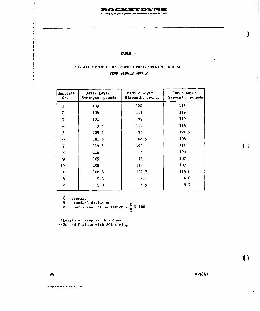
A DIVISION OIP NOAT AMRIUROAN AVIATION. INC.
•TABLE 9
TENSILE STRENGTI OF UNCITED PREIMPREGNATED ROVING
FROM SINGLE SPOOL*
Sample** Outer Layer Middle Layer Inner LayerNo. Strength, pounds Strength, pounds Strength, pounds
1 109 122 115
2 106 111 118
3 101 97 112
4 119.5 11 118
5 105.5 85 121.5
6 101.5 108.5 106
7 114.5 105 111
8 112 105 120
9 109 112 107
10 108 112 107
X 108.6 107.2 113.6
S 5.4 9.1 4.2
V 5.0 8.5 3.7
-- averageS standard deviationV coefficient of variation = S X 100
x
*Length of samples, 6 inches**20end E glass with 801 sizing
()
88 R-364,7
FORM 6098 PLATE REV. 1.-8
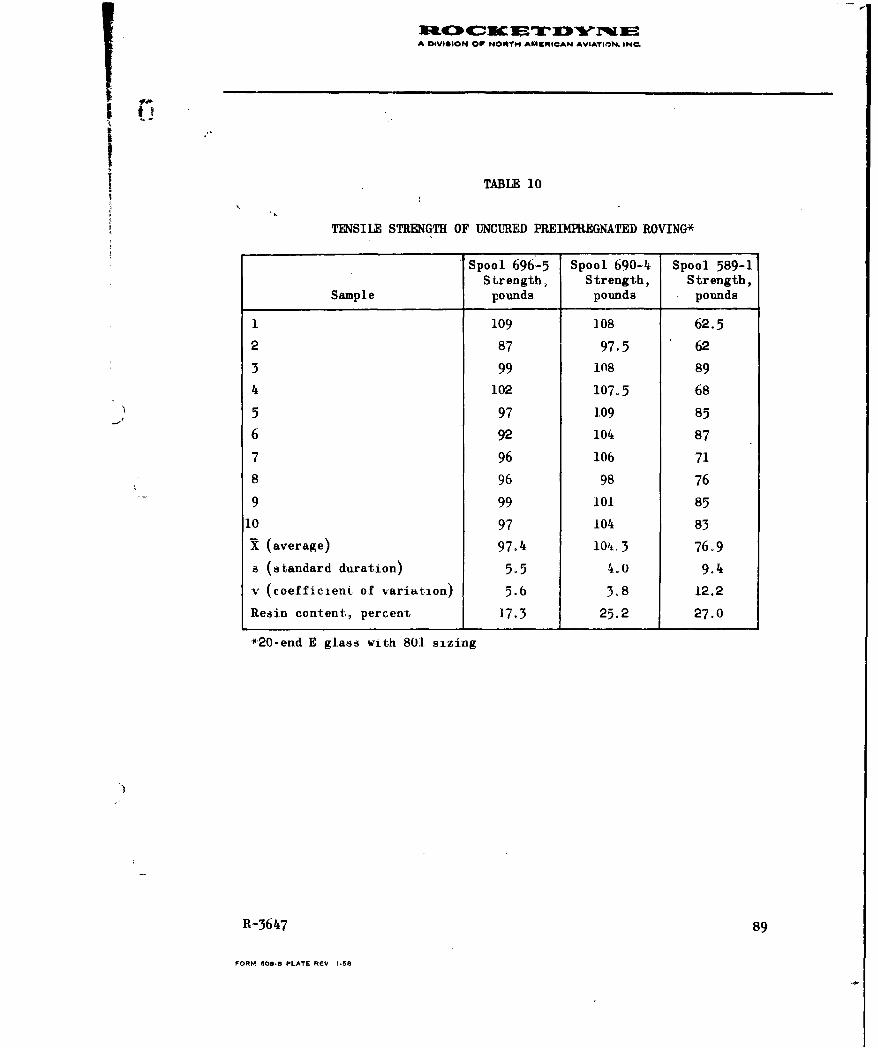
A DIVIGION OP NORTH ANKI ICAN AVIATION. INQ.
TABLE 10
TENSILE STRENGTH OF UNCURED PREIMPREGNATED ROVING*
Spool 696-5 Spool 690-4 Spool 589-1Strength, Strength, Strength,
Sample pounds pounds pounds
1 109 108 62.5
2 87 97.5 62
3 99 1n8 89
4 102 107o5 68
5 97 1.09 85
6 92 104 87
7 96 106 71
8 96 98 76
9 99 101 85
10 97 104 83
X (average) 97.4 104.3 76.9
a (standard duration) 5.5 4.0 9.4
v (coefficient of variation) 5.6 3.8 12.2
Resin content, percent j 17.3 25.2 27.0
*20-end E glass with 801 sizing
R-3647 89
FORM 609.5 PLATE REV 1-58
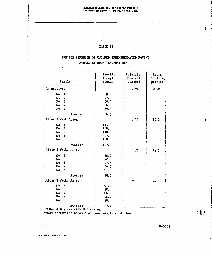
XO4:34C: D W3" ]MA DIVISION OF NORT04 ANEIC:AN AViATION. IN
e
)
TABLE 11
TENSILE STRENGTH OF UNCURED PREIMPREGNATED ROVING
STORED AT ROOM TEPERATURE*
K Tensile Volatile ResinStrength, Content, Content'4
Sample pounds percent percent
As Received 1.91 20.0
No. 1 89.0No. 2 77.5No. 3 90.5No. 4 , 86.0No. 5 89.5
Average 86.5
After 1 Week Aging 1.43 19.2
No. 1 113.0No. 2 109.0No. 3 110.0No.4 97.0No. 5 108.0
Average 107.4
After 2 Weeks Aging 1.73 19.3
No. 1 88.0No. 2 72.0No. 3 77.5No. 4 96.5No. 5 91.0
Average 85.0
After 3 Weeks Aging *. *
No. 1 93.0No. 2 92.0No. 3 86.0No. 4 78.0No. 5 90.0
A-v er age 87.8420-end E glass with 801, sizing
**Not determined because of poor sample condition
90 R-3647
FORM 608-U PLATE REV. 1,50

A OIVIGION OP NORTH AMERI0AN AVIATION. INC
IPackaging Study
In this study, the purpose was to compare two different package designs
and the best method of applying tension to the strand. The two package
designs were a parallel or straight wind (left side of Fig. 31) and a
75-degree way wind (right side of Fig. 31). In this investigation, the
preimpregnated roving used was the same as that which had been used
throughout the program. Two methods of applying tension during winding
were used. One method consisted of resisting the rotation of the spool
of roving. This is described as applying tension at the spool or pack-
age. In the other method, the tension was applied to the strand by
passing it over a system of brakes (Fig. 32).
By using these two methods of applying tension, 3-inch-diameter cylin-
K_ drical samples were fabricated, using material from each package shown
in Fig. 31. The cylindrical samples were tested hydrostatically at room
temperature, and the ultimate hoop tensile strength was calculated: the
purpose was to determine what effect applying tension at the package,
compared with applying tension on the strand, would have on the tendency
to degrade the fiberglass roving. Any degradation would be expected to
show up in reduced strength in a filament-wound sample. Results are
shown in Table 12. The data indicate that some degradation occurs in
the strand when tension is applied at the spool in the case of the way-
wind package. No test of cylinders made by applying tension at the
parallel-wound package was made because of shortage of material. A
repeat test was made on the way-wind package to verify the results ob-
tained in the initial test. This was done because, in the original
experiment, the samples in which the tension was applied to the package
were fabricated before those on which the tension was applied only to
the strand. Since all samples were fabricated from the same spool
I
R-3647 91
FORM 60.B PLATE REV. 1-58

A)VO "Wb07 O NORTH 4MWIRICAN AVIATOON iNrC
P-4
9-4
o
04
54
929
R-64
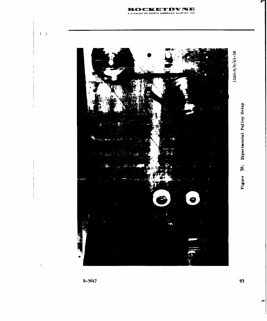
DIflVISION 07 NORTH~ AMCRICAN AVIATION INC
CD,
m.H
R-3647 93
A OIVIION or NORAT6 AM^RIARCAN AVIATIOi, IND.
t
1 Il)
Iof material, there was concern that the package may have been damaged by
applying tension to it, and that this would affect the results on samp-
les made from the underlying material. Results indicate no improvement
on the second test where tension was applied to the strand. Therefore,
applying tension to the package has not harmed the underlying material.
Test values reported in Table 12 were too few to make a conclusive
analysis, but the results obtained so far indicate that applying tension
at a way-wound package of fresh material may not be harmful. However,
this practice is not recommended, since damage might occur if a very
soft package is used or if a package is used where the cohesive action
of the resin would put severe unwinding loads on the strand, possibly
causing degradation of the roving.
During performance of this work, observation was made of the effect on
the package of applying tension at the package. When tension was applied 4to the package, there was no visible effect on the way-wind spool. How-
ever, the parallel-wound spool was damaged by the roving "digging" into
the spool (Fig. 33). This occurred when the roving was fresh, and the
package was relatively soft. After it was aged a few days at room tem-
perature, the roving hardened sufficiently so the package was firm and
not subject to indentation when tension was applied at the spool. Samp-
les for the data presented in Table 12 were fabricated, using this spool
after aging. No further damage occurred on the parallel-wound package.
This experiment indicates one of the possible disadvantages of a parallel-
wound package.
Another potential difficulty of a parallel-wound spool is a tendency for
the package to elongate at the ends as it is wound. This condition would
tend to exist only if the material were soft and sufficient tension were
applied during windup. Under these conditions, flanges would need to be
placed at the ends to support the package. I)
94 R-3647
FORM 0080 PLATE REV. 1.58

A DIVISION OF NORTH AMICRICAN AVIATIOPC INC
I ___ _____ _____ _____ _____ _____X6940___ 12/18/61-1 __Iiue3. Prle-on akaeo ripentdRvnWhr eso a enApida h akg
R-679
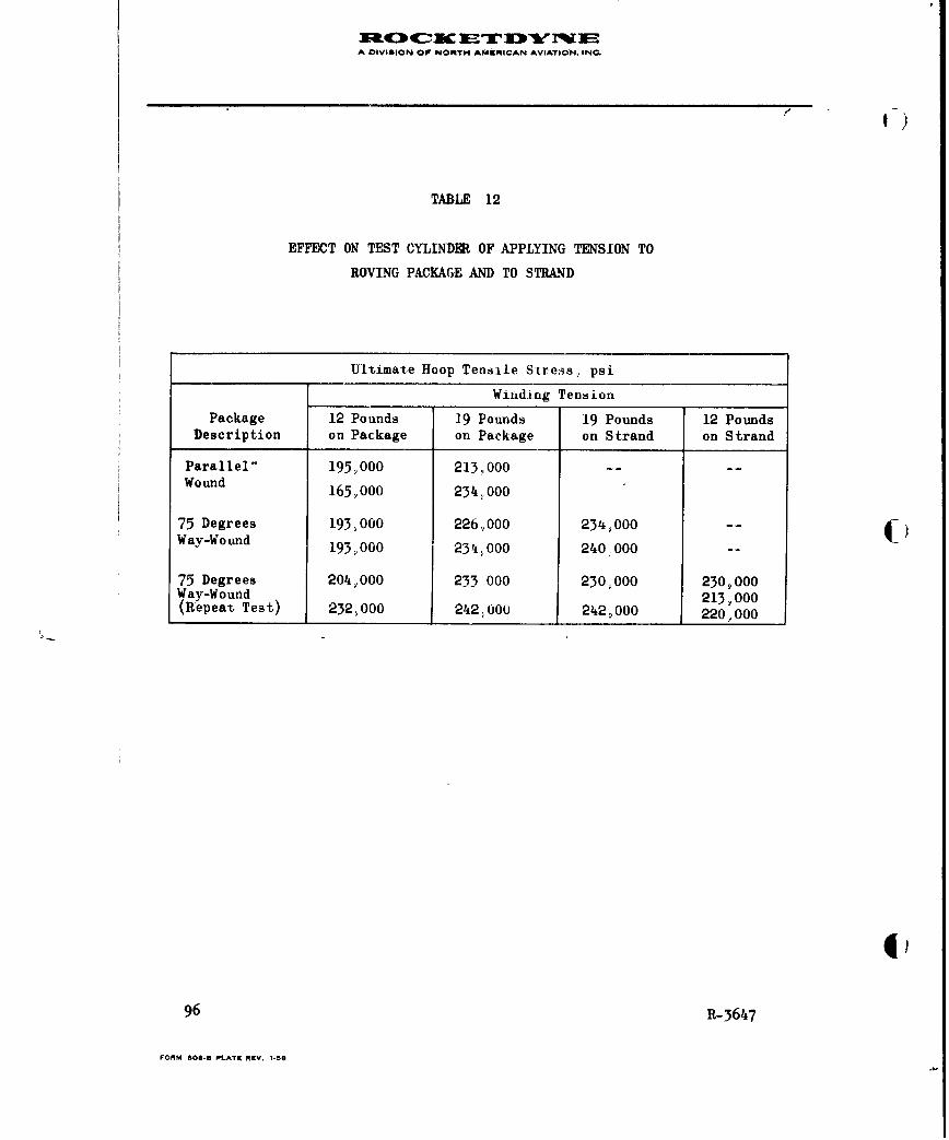
A DIVISION OF NORTH4 AMERICAN AVIATION, INC.
TABLE 12
EFFECT ON TEST CYLINDER OF APPLYING TENSION TO
ROVING PACKAGE AND TO STRAND
Ultimate Hoop Tensile Stress, psi
Winding Tension
Package 12 Pounds 19 Pounds 19 Pounds 12 PoundsDescription on Package on Package on Strand on Strand
Parallel- 195Y00 213.,000Wound 165,.000 23. 000
75 Degrees 193,000 226, 000 234,000 --Way-Wound 193000 234,000 240000 _-
75 Degrees 204,,000 233 000 230,000 230,000Way-Wound 213 000(Repeat Test) 232,000 242,000 242,000 220,000
96 R-3647
FORM 60-B- PLATE REV. I-S

1 DIVISION OP NORTrM.AMICAN AVIATION, INQ.
Certain disadvantages of the way-wind package have been noted. During
high-speed winding, the strand traverses rapidly across the face of the
spool and tends to abrade itself and the underlying material. No study
of this eondition was made. Roving feed rates used throughout the pro-
gram were no higher than 100 4ft/min.
Because of the helical pattern of windup of the package, wide spots
in the roving band are created where the band reverses direction (turn-
around point.) on the spool. When tension is applied to the strand, the
wide spot assumes its normal width condition where the roving is soft
and pliable (but not if the roving has become hardened). This condition
is shown in Fig. 7.
No conclusive evidence has been generated in this study to make a firm
recommendation as to the design of the roving package. It is necessary
to have more experience with each type before a decision as to which is
best can evolve. However, there is sufficient evidence from the study
above to indicate that the best winding procedure is to apply tension on
the strand) and not at the spool. It also appears that a package with
a high way-wound angle (greater than the 75-degree-angle package tested),
but one that is not quite parallel, might he the best solution. This
type of package would eliminate the digging into the spool on the parallel
package and would reduce the abrading and widening effect on the 75-
degree way-wind package.
Winding Machine Components
During this study, investigations were made to determine the effects of
using pulleys of varying numbers, sizes and combinations, the suitability
R-3647 97
FORM 608.05 PLATE REV. 1.58

A OIVISION O NORT64 AMERICAN AVIATiON. INC.
of ceramic guide bushings for use with preimpregnated roving, the type
of equipment-suitable for preheating the roving, and the relative merits
of various tensioning devices.
Guide Bushings and Pulley Systems. The nature of preimpregnated roving
is such that special consideration must be given to the design of certain
components of the winding machinery, Those considered here are the rov-
ing guide devices. It is especially desirable on numerically controlled
winding equipment that the roving be guided from a fixed point on the
delivery arm just before wrapping on the mandrel. Pulley wheels that
pivot to line up with the angle of laydown of the roving are not considered
entirely satisfactory. Consequently, consideration was made of a guide
bushing of the type used as a thread guide in the textile industry. Com-
parative tests were made of a guide bushing made of titanium dioxide and
of a steel roller pulley. The tendency of the roving to be degraded when
passing over or through the device was measured by comparing hydrostatic
burst test data of 3-inch-diameter test cylinders made, using first the
metal pulley and then the ceramic guide bushing on the winding machine.
The burst test data, converted to hoop tensile strength, are presented in
Table 13. Although ,he results indicate slightly lower va3ues when using
the ceramic bushing, the difference is considered to be within experimental
error. Use of a titanium dioxide guide bushing thus was considered satis-
factory without fear of degradation of the preimpregnated roving.
However, in this case, the strand ran nearly stright through the ceramic
guide bushing, Later experiments used similar guides mounted on the large,
numerically controlled machine. The strand was bent at a sharp angle
98 R-3647
FORM 60S.S PLATE REV. 1-58

A DIVIUON OF NORi4 AMERICAN AVIATION. IN-.0
I TABLE 13
TEST RESULTS OF CYLINDERS WOUND USING CERAMIC BUSHING AND
STEEL PULLEY ROVING GUIDES
Sample Hoop TensileNo. Follower Strength, psi
1 Ceramic Guide 252,000Bushing
2 Ceramic Guide 246,000Bushing
3 Ceramic Guide 237,000Bushing
4 Ceramic Guide 251,000Bushing Average 244,100
5 Steel Pulley 258,000
6 Steel Pulley 272,000
7 Steel Pulley 240,000
Average 256,666
Difference: 256,666-244,100
12,566
12,566 x 100256,666 - 4.89 percent
4
R-3647 99
FORM aO89D PLATE REV. 1-58

A OIVISIOM OF NORTH AMIRICAN AVIATION, IN.
around the edge of a ceramic bushing during the winding operation. At the
point of contact, excessive strand friction was noted and caused both
filament abrasion and erratic variations in winding tension. Further
evaluation of ceramic guide bushings was terminated. Use 6f these bush-
ings is not recommended under these conditions.
Also of considerable interest in the design of components for winding
machinery is the nuber and arrangement of guide pulleys that may be
used without causing damage to the preimpregnated roving. To evaluate
this problem, an experimental mounting plate was used to set up the vari-
ous multiple pulley and brake combinations shown in Fig. 32 , 34 , and
35. In using the various setups, 3-inch-diameter cylinders were wound
and tested hydrostatically. The test results, converted to hoop tensile
stress, for each system tested are presented in Table 14. The spread
of test results is within normal experimental variation* for this type
of testing, except for specimen PT-9 which is considerably lower than
the others in the series and tends to unduly influence the average.
However, even if this is taken into consideration, it, would appear that
there is a slight amount of deterioration occurring with the 10-pulley,
180-degree contact installation, compared to the 2-pulley setup. This
is mitigated slightly by reducing the contact surface to 90 degrees.
Another consideration negatively influencing the use of many pulleys is
the possibility of tacky strands of material -tending to wind around the
pulley and to break. Consequently, it is recommended that the number of
guide pulleys used in winding machinery be kept at a minimum for most
reliable operation.
*This statement is strengthened by the scatter of data where the lowvalues of one set overlap the high values of the other.
41)
100 R-3647
FORM 608.0 PLATE REV. 1.58
DIVSIO O NOT4 CIN IrIO N
Id'0
P-4
'A4
R-3647 101
la43 C- 1w 1- ir X31% FA DIVISION OF NOMTH AMKMICAN AVIATION. INC
00
p42
41
IOTA"
14
.4S
102 R34
IA DIVIGION O'NORTH AMER~ICAN AVIATION. INC
TABLE 14
EVALUATION OF THE EFFECTS OF A MULTIPLE PULLEY FEED SYSTEM
FOR USE WITH PREIMPREGNATED ROVING
Hoop TensiletSample Stress, 3-inch Dia
No. Pulley System Arrangements Test Cylinders, psi
PT-4- Feed system of 2 brakes, and 2 guide 256,000PT-5 pulleys. Winding tension 18-20 lb 253,000PT-6 on single 20-ena strand (Fig. 10) 250,000PT-10 251,000PT-li 251,000PT-12 240,000PT-20 235,000PT-2 1 246,000PT-22 228 000
Average24,0
PT-i Feed system of 2 brakes, 2 guide pulleys 234,000PT-2 plus 8 guide pulleys added to system 242,000PT-7 with 180-deg contact with roving strand 250,000PT-S (Fig. 11) 247,000PT-9 006m00
Average-i36000
PT-13 Feed system of 2 brakes, 2 guide pulleys 252,000PT-14 plus 8 guide pulleys added to system 244,000PT-i5 with 90-deg contact with roving strand 244,000PT-16 (Fig. 12) 250,000PT-17 246,000PT-18 233,000PT-19 249,000
______________________________Average 245,000
Note: All pulleys used were 1.5- and 2.O-in.-dia. nylon sleeves overball bearings
R-364710

A DIVISION OP NORTH AMRICAN AVIATION. INC
-)
Materials for Pulleys and Guide Devices. Guide bushings and pulley spools
made from Teflon were used to handle strands of preimpregnated roving in
winding. Abrasion from the glass reinforcement in the strand rapidly cut
into this relatively soft plastic.
A sleeve for a guide pulley was made from Kel-F. As in the case of Teflon,
the glass reinforcement in the strand cut into the plastic surface of the
pulley. Kel-F resisted abrasion better than the Teflon pulleys previously
tested.
Nylon pulleys were found to be more resistant to abrasion than either
Teflon or Kel-F. The Nylon rollers were found to be the most satisfactory
of the plastic materials tested. The tendency of the roving to adhere to
the Nylon was not significantly different from that found for Teflon or 4-
Kel-F.
Steel pulleys and guide rollers were used in connection with winding
operations. The glass strand did not cause apparent damage to these sur-
faces. However, metal surfaces, in general, showed a greater tendency to
pick up tacky resin than the plastic rollers evaluated.
Preheating Equipment. Preheating equipment was produced for use with the
aging study. This equipment heated the roving just before placement on
the mandrel by passing it through a chamber heated by a hot air flow
(Fig. 3 ). The equipment vab satisfactory, but the study indicated that
preheating of the roving is not required. No further effort was expended.
10 R-3647
FORM 000B PLATE REV. 1.58

A DIViOION O lP ihOfTYM AU~ftS@AN AVIATION. [email protected]
C
Tensioning Devices. Simple mechanical brakes were proved adequate where
strand feed velocity was kept nearly constant. A mechanical device
allowing dynamic friction laoding to be relatively stable over a wide
range of strand feed velocity was tested and was found to be inadequate
for low-end-count strands-. The device is probably suitable for strands
having a high end count.IAs a result of problems encountered in using hysteresis brakes (reported
by other companies under Navy contract), Rocketdyne did not believe this
tensioning method required further study. A magnetic clutch was assembled
for study as a tensioning and slack-takeup device. Evaluation could not
be completed for inclusion in this report as it became apparent that a
full investigation of tensioning devices must consider the entire delivery
system and the winding procedure used. To define adequate tensioning pro-
cedures for any equipment exceeded the limits of this program.
Optimum Tensioning Technique
It was determined that, for small test cylinders, the tension should be
applied to the strand rather than to the spool, regardless of package.
Since the effects of strand abrasion are believed less for the small
test cylinders than for large components, it is recomnended that tension
be applied primarily to the strand during winding.
Controlled Strand Tension
This study is related to the tensioning devices and complete delivery
system used and was determined to be beyond the scope of this program.
Considerably more effort regarding this subject is highly desirable.
R-364t7 105
FORM 608- PLATE REV. I-96

A DIVISION OP NOWTN AMIRICAN AVIAVION. INC.
Methods for Winding with Multiple Strands
Equipment for evaluating multiple-strand winding was constructed. One
case was made with two strands of roving. Additional effort is required
to evaluate the use of a larger number of strands in multiple-strand
winding.
Accurate Placement of Strands During Winding Operations
In experiments described in the next section, and in observations of
strand placement, the NTC equipment produced a more precise pattern than
did the mechanically controlled equipment; however, additional units would
need to be made and tested on both types of equipment before a definite
conclusion could be reached regarding the absolute influence of the pre-
cision strand placement. 4)
In addition to winding cases to determine the relative precision of'the
NTC and the mechanically controlled machine, windings were made on test
patterns for both types of equipment. This study was performed by wrap-
ping a mercerized cotton thread around a mandrel and measuring the
spacing between strands. Examples of such patterns are shown in Fig. 1,
28, and 29. These measurements have indicated that the NTC machine is
capable of winding a pattern such as Fig. 1 shows to a tolerance on
spacing of ± 0.01 inch. A tolerance of strand spacing as wound on the
mechanically controlled machine was found to be approximately ± 0.06 inch.
4)106 R-3647
FORM 08.0 PLATZr RtV. 1.50
A OIVItION @1 NOMNTH AMPiRICAN AVIATION. INC.
C
CASE WINDING STUDIES
Under this portion of the program, six 18-inch-diameter x 24-inch-long
cases were fabricated. Five of these cases were fabricated with the
numerically tape-controlled winding machine. One case was fabricated on
mechanically controlled winding equipment. For purposes of comparison of
test data, the test results of a case previously made and tested under
another program are included in the following discussion. This seventh
case is identified as ABL 10.
The objectives of the program, the implementation of these objectives, the
fabrication procedures used, the test methods followed, and a discussion of
the test results are presented.
OBJECTIVES AND TEST PROGRAM
The basic objectives of the case winding studies were:
1. To compare the effects of the precise winding patterns performed
by the numerically controlled winding machine with those produced
with mechanically controlled equipment.
2. To study the effect of voids on the laminate stress level.
3. To compare the quality and strength of cases made with wide-
band roving with cases made with standard width roving.
4. To compare the use of wide-band roving made up with a number of
strands laid down at once with the use of a single strand.
1,
R-3647 107
FORM SO0.3 PLATE NEV. 1.58
A DIVISION OF NORTH AKARICAN AVIATION. INC,
El)
To implement these objectives, one case was fabricated using wide-band
material, and the same mechanically controlled equipment used to fabricate
the ABL 10 vessel. The ABL 10 vessel was fabricated with standard width
roving; thus, a comparison was to be made of wide-band vs standard width
band, as fabricated on mechanically controlled equipment. The vessel,
fabricated under this program, was designated S/N 1.
To compare the quality and strength of cases made on a numerically tape-,
controlled machine to the cases made on the mechanically controlled equip-
ment, two vessels were fabricated on the NTC machine; one of standard
width band material and one of the wide-band material. These cases were
designated as S/N 4 and S/N 5, respectively. To get a direct comparison
between the cases made on the NTC machine with cases made on mechanically
controlled equipment, the winding patterns and spacings selected were 4)essentially identical on both types of equipment.
To study the effects of voids in a case, two vess4s, S/N 2 and S/N 3, were
fabricated on the NTC machine. The same type of roving was used for each
vessel, however, the spaAng and number of layers were different. With
aase S/'N 2, spating for the longitudinal layers was selected so that no
voids resulting from narrow bands or band width variation could occur.
Spacing of the cir.umferential winding was such that a 50 percent overlap
of the band oc, urred. The circumferential windings were purposely applied
to assure burst in the dome section of the tank for both S/N 2 and S/N 3.
With the S/N 3 vessel, the longitudinal windings were applied in two layers
with the band spacing such that it was exactly doubled that used for S/N 2.
This spasing was greater than the average band width to ensure a gap between
the strands as applied on the mandrel. The circumferential windings for
S/N 3 and S/N 2 were equal in number, and weights of the cases were designed
to be identital.
108 R-364,7
FORM 608.5 PLATE REV. 1.5
A DIVISION OF NORT44 AMERICAN AVATiON. INC.
To compare the effect of winding with more than one strand to obtain a
wide band, case S/N 6 was fabricated with two 20-end strands of roving,
and at spacings double that of each layer applied in case S/N 2.
It was planned that all cases should be tested by hydrostatic burst
without strain gages.
Fabrication
All of the cases were nominally 18 inches diameter by 24 inches long.
The configuration conformed to the Allegheny Ballistic Laboratory design
ABL 6400A. All cases were fabricated on mandrels of water-soluble plas-
ter which was subsequently washed out of the cured case. The cases were
constructed of E-HTS fiberglass roving preimpregnated with E787 resin
system. In all cases, except S/N 6, a single 20-end strand was used.
The width of the strand used for each case is shown in Table 15. Case
S/N 6 was constructed using two 20-end strands.
Cases were constructed using a combination of longitudinal and circumfer-
ential windings (Fig. 36). The longitudinal fibers were placed at a 7-
degree helical angle such that the strand progressed from the side of
the metal boss at one end to the opposite side of the metal boss at the
other end. This is sometimes called polar wrapping. The circumferential
wrappings were extended slightly beyond the 13-1/4 inch length of the
cylindrical portion of the case. For case S/N 1 through S/N 6, the long-
itudinal windings were sandwiched between the inner and outer layers of
circumferential windings. The ABL No. 10 case (made and tested previ-
ously during a company-sponsored program) was made with all circumferential
R-3647 lo9
TABLE 15
ABL io s/Ni1 SIN
Purpose of Test Qualification, Wide Band, No Void
Equipment Used, Mechanical Mechanical NTC
Material
Roving One Strand One Strand One St20-End E-HTS 20-End E-HTS 20-Eid'
Resin System E-787 E-787 E-78
Roving Bandwidth, nominal inch 0.085 0.125 0.09
Strand Spacing, inch
Circumferential 0.045 0.045 0.04Longitudinal 0.071, 0.074 O.0
Weight of Resin and Reinforcement,pound 4.66 4.36 7.801Inside Diameter, inch 17.939 17.877 17.8
Wall Thickness, inchTotal 0.046 0.044 0.OELongitudinal Plies Only 0.019 0.015 0.0
Maximum Hydrostatic Pressure, psi 750 540 9
Ultimate Tensile Stress, Laminate, psiComposite 146,000 110,000Unidirectional Laminate
Longitudinal Plies 178,000 162,000 176,o(Hoop Plies 249,000 167,000 *
Ultimate Tensile Stress, FiberglassOnly, psi
Longitudinal Plies 253,000 249,000 269,o(Hoop Plies 354,000 257,000 *
Resin Content, Percent by Weight 16.6 20.6 19.8
Burst FailureLocation Transition Cylinder Transi-Orientation of Fibers Where
Failure Occurred Longitudinal Circumferential Longiti
*Total bandwidth of the two strands, as applied to the mandrel.*These cases designed to burst in dome sections and circumferential windings V
therefore, composite wall and hoop plies stress is no true indication of perf.
110
nlovw er on TNRGA MNOfA UWSMN SP NUYIN *U YSSU. m.
TABLE 15
DATA FOR 18-INCH-DIAMETER BY 24-INCH-LONG CASES
_ S/N i S/N 2 S/N 3 S/N4 S/N 5 6
on, Wide Band, No Voids, Voids, Narrow Band, Wide Band, Multiple Strand,Mechanical NTC NTC NTC NTC NTC
One Strand One Strand One Strand One Strand One Strand Two StrandsS 20-End E-HTS 20-End E-HTS 20-End E-HTS 20-End E-HTS 20-End E-HTS 20-End E-IHTS
E-787 E-787 E-787 E-787 E-787 E-787
0.125 0.090 0.080 0.085 0.125 0.145*
0.045 0.044 0.044 0.044 0.044 0.0880.074 0.055 0.110 0.074 0.074 0.110
4.36 7.80 7.41 4.61 4.55 7.01
17.877 17.875 17.854 17.826 17.824 17.876
0.044 0.085 0.082 o.o46 0.047 0.0770.015 0.025 0.025 0.017 0.018 0.023
540 980 1025 650 920 1020
110,000 ** 126,000 174,000
162,000 176,000 184,000 172,000 229,000 199,000167,000 ** ** 200,000 283,000
249,000 269,000 282,000 258,000 352,000 292,000257,000 ** 300,000 435,000 --
20.6 19.8 20.0 19.0 20.2 18.1
Cylinder Transition Transition Transition End Dome End Dome
Circumferential Longitudinal Longitudinal Longitudinal Longitudinal Longitudinal
o the mandrel.nd circumferential windings wer.e thicker than required;is no true indication of perfo, nance for these cases.
R-3647

DIVIION rNAMRICNAVIATIONIN
X6940-6/29/62-2AFigure 36. Case S/N 4 Before Test
R-364711

j A DIVISION Of NORTh AMRMICAN AVIATION. IN.
windings placed over the longitudinal windings. During winding of the
cases, the tension on the 20-end strand was adjusted to 16 to 18 pounds.
The wide-band roving was used in cases S/N 1 and 5. It was anticipated
that a wide roving band, which is thinner, would nest and consolidate
better than a thicker, narrower band. The material used was 20-end rov-
ing which had been processed by the supplier into a nominal 0.125-inch
band. The uniformity of the band width was very poor, ranging from
0.080 to 0.150 inch. Where the band width was very wide, there was a
tendency to separate into two bands. This occurred especially where
the roving wound around the 75-degree way-wind package. The band also
had a tendency to curl into a more narrow strand after leaving the last
delivery pulley and before contacting the mandrel. Even though theme
deficiencies in the wide-band roving did exist, the nominal band width
was still considerably wider than obtained with the standard material, ()and definite advantages over the standard band width material may be
obtained with its use.
Since cases S/N 2 and 3 were designed to determine the effect of voids
in the case, both cases were made with slightly more material in the
hoop diiecLion than was necessary for balanced construction to ensure
failure in the end dome. S/N 2 was made with a combination of roving
bandwidth and spacing to ensure overlap of the strand in the longitudinal
winding. Case S/N 3 was made with a strand placement of 0.110 inch
which was slightly greater than the 0.080-inch nominal bandwidth of the
roving to ensure gaps and, consequently, voids in the laminate, The
mechanics of fabrication required that the cases be made slightly
heavier than the other cases in the series. The total weight of material
in each case, S/N 2 and 3, was practically the same. During fabrication
of case S/N 2 some difficulty was experienced in winding of the
112 R-3647
FORM SO-S PLATE REV. 1.58

A DIVISION OP NOMT1M AMVNRICAN AVIATIOW. IN.
longitudinal layers which required stopping and starting of the equipment
Excess windings applied during restart operations had to be removed each
time this occurred, and the tension of the roving was somewhat changed
for these particular areas in the case. During removal of the excess
windings, some of the longitudinal fibers were inadvertently cut in the
cylindrical portion; this also may have had an effect on the performance
of the case.
Difficulties similar to these which occurred on case S/N 2, described
above, also occurred on case S/N 4; however, no fibers were cut on
this case. Other defect. also occurred in some of the cases. In two
tU of the cases, small flat spots about the size of a quarter were caused
by localized collapse of weak spots in the mandrel. In'another a knot
in the roving was wound into the structure. All of the known defects
were carefully catalogued and their locations marked on the external
surface of each cured case prior to hydrostatic testing. In no
instance did failure occur at one of these defects, nor did the failed
area include a section containing a known defect.
After fabrication, the cases were cured in a circulating hot air oven.
The cure cycle consisted of 1 hour at 150 F, 1/2 hour at 250 F, I hour
at 300 F and 3 hours at 350 F. Case S/N 1 was inadvertently submitted
to a cure cycle where exposure to each temperature was approximately
twice as long.
Testing
) Prior to hydrostatic testing, a rubber bladder was inserted in each
case. Pressurization was performed with the case mounted horizontally
in a fixture (Fig. 37). The pressure was raised at a steady rate to
550 psi in approximately 2 minutes. After a 1-minute dwell at this
pressure, it was again increased at the same rate until failure.
R-3647 113
FORM 603.3 PLATE REV. 1.-5
A OgWeSON OF NPf0T14 AM944CAN AVI&TION INC
P-1
w a
-. 0
A DtVISION OP NONTH AMENICAN AVIATION. IN06
This occurred in the end domes by failure of the longitudinal fibers.
Initial failure usually occurred at the transition point (illustrated in
iFig- 38, 39 and 4O)In bases SIN 5 and S/N 6, the failuie, apeiktdto initiate in the curvature of the end dome rather than directly at the
point of transition (shown in Fig. 41 and 42). Although it appears that
S/N 5 failed by blowing out the end boss, close examination indicates that
the initial failure occurred in the longitudinal fibers in the curvature
about 1 to 2 inches from the transition point. More than half of the
fibers adjacent to the end boss remained intact.
The mode of failure for Case S/N 6' (Fig. 42) was similar to S/N 5. The
construction of S/N 6 was similar to S/N 2.
Before and during testing it was noted that a considerable amount of craz-
_ ing of the resin occurred. This was visible in the end domes only. The
visible pattern of crazing was always parallel to the direction of the fiber.
A diamond-shaped pattern occurred when crazing in both layers of the longitu-
dinal wrap occurred and was visible through the surface resin. Crazing was
most evident in S/N 2 and 3, probably because the case walls were thicker.
Figure 43 illustrates the crazing evident before testing in case S/N 2.
Crazing of this type had not occurred in cases previously made and tested
at Rocketdyne
A number of days elapsed between the removal of the mandrel from case S/N 3
and the testing of this case. Crazing was evidenced as soon as the mandrel
was removed; it grew progressively worse during the storage period between
mandrel removal and case testing.
R-3647 115
FORM 09.3 PLATE REV. 1.50
A DIVISOON I' P40N~ AMCNICAN AVIATION. INC
6940-7/5/62- 1
Figure 38. Came S/N Ii After Burst Test
116 R- 36'47
NWo 4C ' U E F ""rr~ EA DIVISION OF NORTH AMERICAN AVIATION INIC
X694-6/29/62-2B
Figure 39. Cases S/N 2 and S/N 3 After Burst Test
R-361i7 117
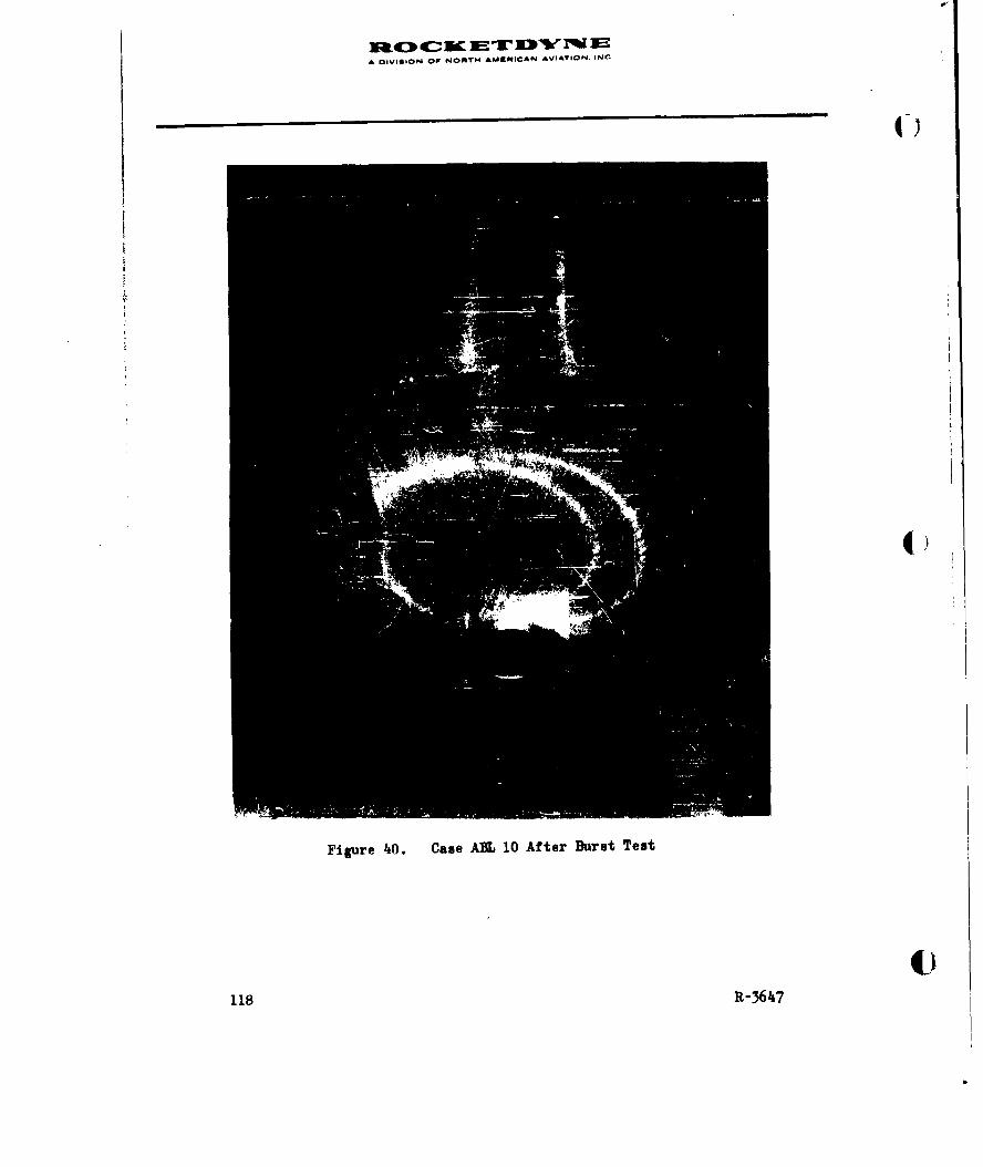
A flIVISION OF NORTH AMERICAN AVIATION. INC
Figure 40. Case A13L 10 After Burst Test
118 R-3647
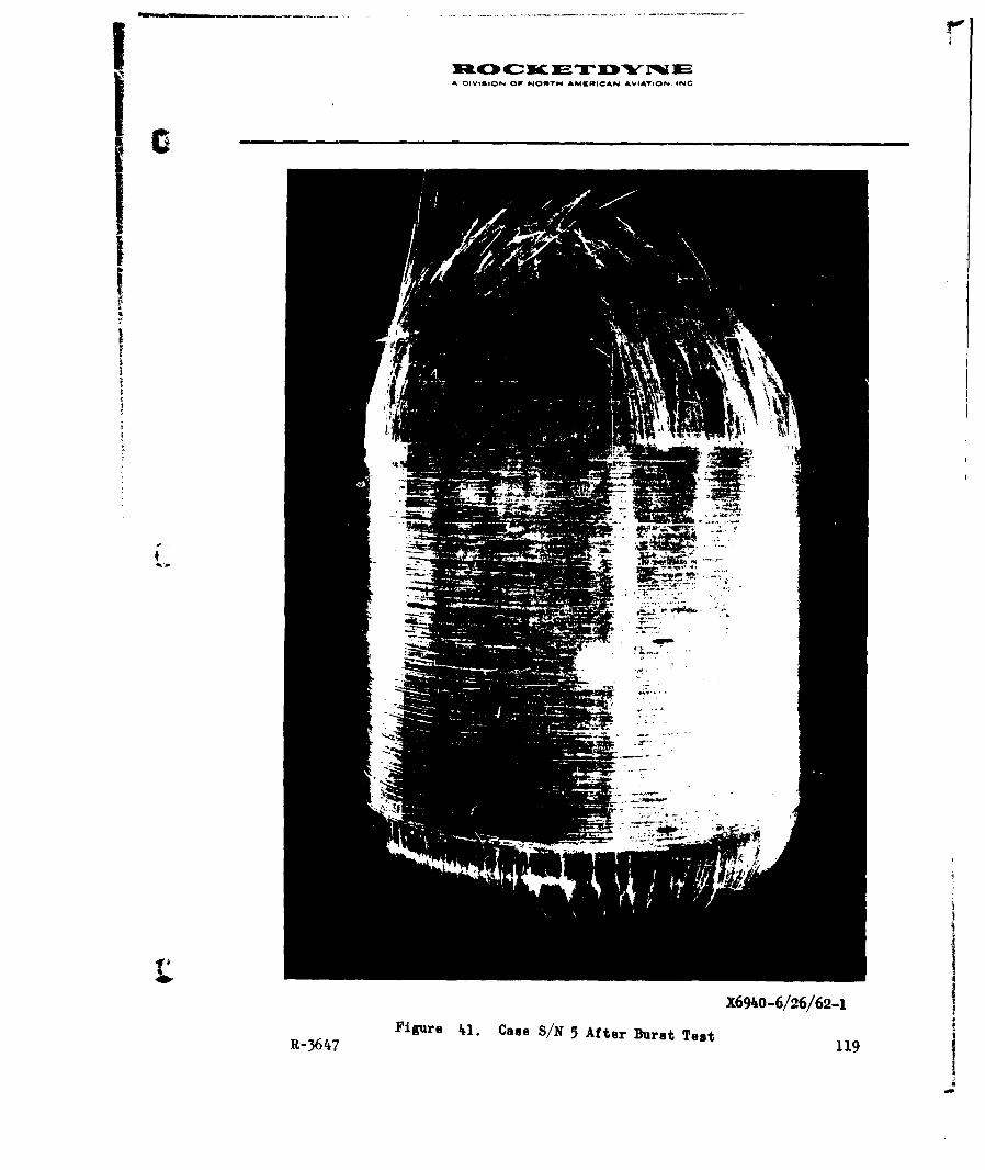
D IVISION OFP N0RTH AK49RICAN AVIA7.ON INC
X69-6/26/62-1I
R-67 Figure 41. Case S/N 5 After Bu~rst Test 119

ADIVISION OF NOWTH AMCMIOCAN AVAIION. INC
X6920-7/5/62-1Figure 4i2. Came S/N 6 After Burst Teat
120 R-364~7
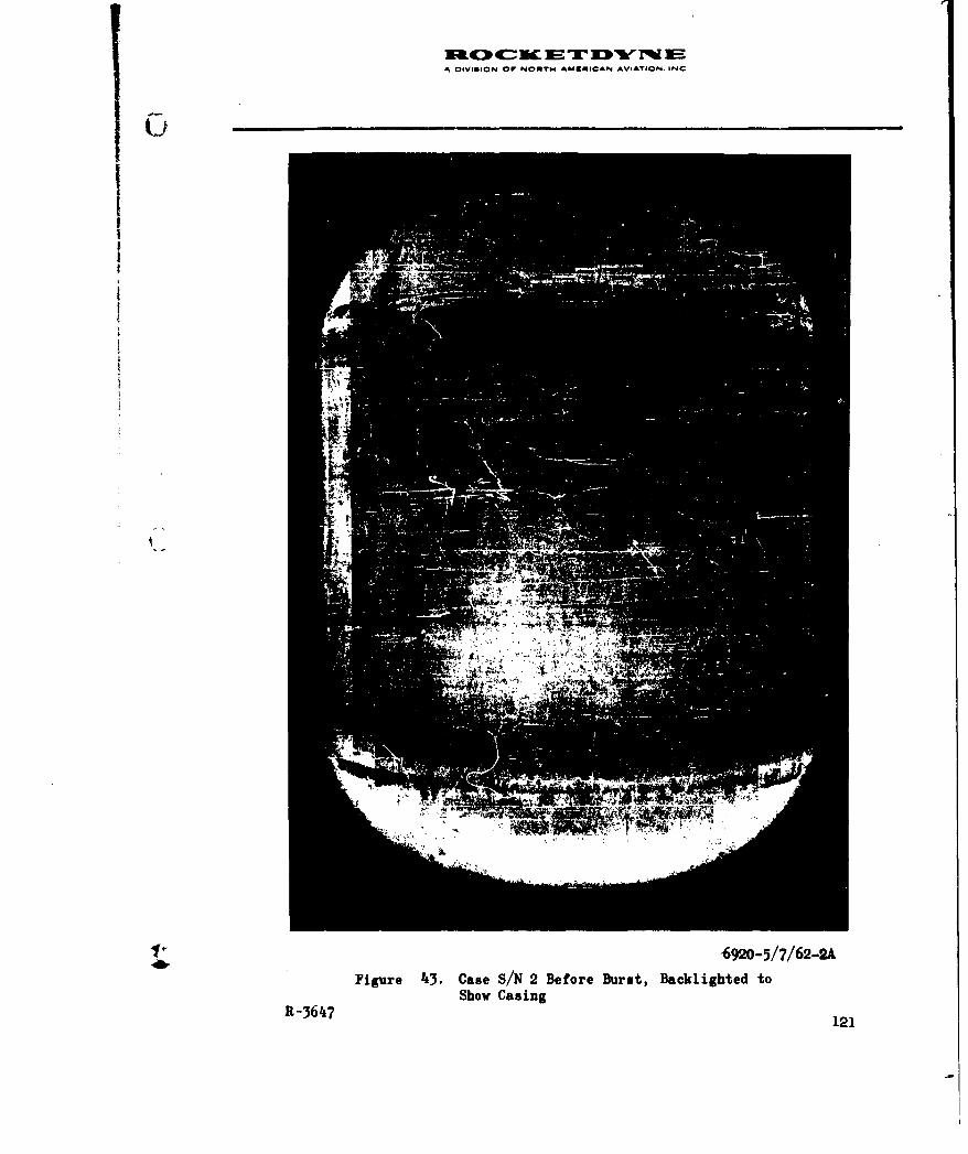
uc0 C SC M -r 13'erMWA DIVISION OF NORTH AMERICAN AVIATION, INC
MO
'6920-5/7/62-2A
Figure 4i3. Case S/N 2 Before Burst, Backlighted toShow Casing
R-36I47 121
AOIViSION OF NONTH AMRICAN AVIATION i--C
6)
The exact causes for the crazing are not readily explained. Tension
effects, resin shrinkage, and variations in coefficients of thermal
expansion are probable factors contributing to the crazing observed.
Considerably more effort would be required to determine either the
causes or the effects of the crazing observed for these cases.
On examination of the cured laminate, resin-filled gaps between adjacent
strands were evident, although these gaps did not appear to be quite so
great as originally intended.
DISCUSSION OF TEST RESULTS
The data summarizing test results of the six cases made during this
program, and the ABL 10 vessel, are presented in Table 15. Note that
cases S/N 2, 3, and 6 were designed to assure burst in the dome section
and, therefore, the results expressed are given in terms of the stress
in the longitudinal direction only (i.e., stress was based on the
thickness of the layer(s) containing the longitudinal filaments).
Stress values presented are based on the laminate consisting of the
combination of fiberglass and resin. This method of presentation
includes the wall thickness contribution of the resin, and, therefore,
is an indication of the strength-to-weight value. In addition, "glass
stress" values are presented. In determining this value, the resin is
assumed to make no contribution to the undirectional tensile stress and
therefore should be discounted from the cross-sectional area of the
material under stress. The value of this presentation is that the
clouding effect of the resin content is removed from the analysis when
making comparisons among a variety of test samples. In the following
analysis, it should be noted, cases S/N 1 through 6 have nearly the same
122 R-3647
IF'ORM O0B.U PLATE 3EV. 1.38
I
A OMMBON OF NORT14 AMK1ICAN AVIATION. INC.
resin content and can therefore be compared on the basis of either method
of presentation of stress values. Case ABL 10 has a significantly lowerresin content. Therefore, comparisons with the other cases should be
based on glass stress values.
Use of Wide Band Roving
The use of wide-band material can be compared to narrow-band by comparing
cases S/N 1 and 5 to ABL 10 and S/N 4. However, S/N 1 was inadvertently
subjected to an incorrect cure cycle. It is believed that this cure
schedule may have an adverse effect on the mandrel and, possibly, the
case material, and thus upon the results obtained for the wall stress of
this vessel. The results obtained on case S/N 1 are probably of little
value and should not be included in the analysis. Consequently, S/N 5
remains as the only valid sample made with wide-band roving. Since the
ABL 10 case was made on the mechanically controlled machine, the only
valid comparison remaining is between S/N 4 and 5.
Case S/N 5, made with wide-band roving, performed significantly better
than S/N 4. The stress which developed in the longitudinal plies where
failure occurred was one-third better in S/N 5 than in S/N 4. Some
difficulties were experienced with the functioning of the NTC machine
during fabrication of S/N 4, requiring stopping and starting of the
machine. On the other hand, the wide-band preimpregnated roving material
was not uniform in width, varying from approximately 0.065 to 0.150 inches.
It is difficult, then, to state without qualification that the wide band
made a significant improvement in performance. Indications are that some
definite benefit was derived from its use, but other test samples would
be required to make a more firm conclusion.
R-3647 123
FORM 600- PLATE REV. I-58
A 4VISION OP NONTN AARRICAN AVIATION, INCLI
IIEffect of Voids on Stress Level
Cases S/N 2 and 3 were designed to determine the effects of voids and gaps
in the case. As described earlier, the longitudinal windings in S/N 3
were spaced far enough apart to create gaps between the strands. It was
intended that this would result in voids, or air pockets in the laminate.
These voids, if present, would be visible because of the transparent
nature of the structure. However, the resin flowed during cure and filled
in the gaps to the extent that no significant amount of voids was visible.
A comparison of the performance of S/N 2 and 3 shows no significant
difference. The hydrostatic burst pressures were 980 and 1025 psi,
respectively. The lower value for S/N 2 may have been due to the difficul-
ties experienced during fabrication.
The calculated wall stress values, based on the logitudinal laminate ()thickness where failure occurred, were only 4 to 5 percent apart. It
would seem that, based on these data, there is no significant effect on
the case when there are gaps between the windings which are filled with
resin.
No conclusions can be made regarding voids (air inclusions) in the
laminate from these preliminary data since no voids were evident. These
data indicate that, for a pressure vessel, gapping between the strands
can be tolerated and may even be preferred to an irregular overlapping of
strands. However, there is insufficient evidence, because too few samples
were available to substantiate these conclusions. Further, it is often
important with filament-wound vessels that the wound structure be stressed
in compression or bending, as well as in tension. Although the effect of
gaps may be insignificant with reference to tensile loads, the same
degree of gapping in the laminate may quite possibly be quite detrimental
124 R-3647
FORM 608.3 PLATE REV. 1.56-e
A DIVII014 OP NORTH f AMUNICAN AVIATION. INC.
to performance with reference to either compressive or bending loads.
On this program the controlled gap was approximately 35 percent of the
band width during the winding, and the evidence obtained from the cured
laminate indicated that an even lower percentage of gap existed in the
cured structure. Considerably more effort should be expended, for the
reasons listed, to define the allowable limits for gaps between strands
in filament-wound structures. These additional studies should include
not only hydrostatic loading of vessels but compressive and bending
loading of vessels.
Multiple Strands
The use of multiple strands of preimpregnated roving combined into a
single wide band was incorporated in the fabrication of case S/N 6.
This case was designed to apply the same amount of roving per layer,
and the same number of layers, which was used in case S/N 2. Two
strands of 20-end, standard width band, preimpregnated roving were used
during the winding. These strands were overlapped to form a band 0.145
inch wide. To obtain the same amount of roving per layer as used in
case SIN 2, the strand spacing was doubled that for S/N 2. No difficul-
ties were encountered during the winding of this case. No strand breakage
or machine difficulties of any sort were encountered. In comparing the
performance of S/N 6 to S/N 2 the difficulties experienced during
fabrication of S/N 2 should be considered. The fact that a slightly
greater stress level based on the thickness of longitudinally reinforced
layers was obtained for S/N 6 than was obtained for S/N 2 can be partially
explained by this lack of defects in S/N 6 which were present in S/N 2.
U
R-3647 125
FORM BOSB PLATE RBV. 1.5S
A DVISION OP NORTt4 AM f|AN AVIATIOn, IN.
Although the indications are that multiple strands can be used with
results equally as good as with single strands of roving, insufficient
data are available to substantiate this conclusion. More effort is
required to completely define the limits for processing with multiple
strands of preimpregnated roving on the numerically controlled
equipment.
NTC Machine vs Mechanically Controlled Equipment
ABL 10 case, fabricated as part of another program, was selected for
comparison purposes as representative of the best case made on the
mechanically controlled equipment. Case S/N 1, 4, and 5, fabricated
on the NTC machine, were basically the same contruction as ABL 10.
Comparisons involving S/N I and 5 must consider that wide-band roving
was used. However, S/N 1 is considered an unsatisfactory sample because
of the improper cure cycle used, as discussed above. Direct comparison
of cases made on the mechanically controlled machine and the NTC equip-
ment can only be made between ABL 10 and S/N 4 and 5.
Case S/N 4--constructed in the same way as ABL 10, including the use of
narrow roving--performed equally as well as ABL 10, comparing the glass
stress of the longitudinal plies where failure occurred with each. In
the light of the difficulties encountered during fabrication of S/N 4
which were not experienced during fabrication of ABL 10, the performance
of S/N 4 can be considered superior to ABL 10.
Case S/N 5--const--,cted in the same way as ABL 10, except for use of
wide-band roving--performed considerably better than ABL 10. This case,
made on the NTC machine, developed during test a unidirectional laminate
1.26 R-3647
FORM 608.S KLATE RV, t.58

A OIVIGuON Or NOMT4 A1MWK~IAN AVIATION. IN.
stress of 229,000 psi for the longitudinal ply and 283,000 psi for the
circumferential plies. These values are based on the observed thicknessof each ply. The stress in the circumferential direction compares
favorably with an average value of 270,000 psi obtained on cylindrical
test specimens on other programs using the same material. Reference is
also made to the glass stress of 435,000 psi in the hoop direction.
This value approaches the ultimate monofilament strength of 500,000 psi
for E-HTS glass, It seems possible that, since burst failure did not
occur in the hoop direction, the developed stress was not the ultimate
possible for the hoop fibers in this case. No difficulties were
encountered during fabrication of case S/N 5. It is entirely conceiv-
able that this case represents a performance level that can be readily
duplicated on the NTC machine.
Cases S/N 2, 3 and 6, made on the NTC Lachine, wore not constructed
as ABL 10 was, and a direct comparison of performance theoretically can
not be made. However, these cases failed during test in the same
manner as ABL 10 failed. All three,evaluated on the basis of glass
stress in the longitudinal plies, performed better than did ABL 10. It
is now apparent that all the cases made on the NTC equipment developed
a higher glass stress in the longitudinal plies where failure occurred
than did ABL 10. Since ABL 10 represented the best made on the
mechanically controlled equzipment, it can be concluded that the NTC
machine can readily produce a superior filament-wound product using
preimpregnated roving.
R-3647 127
FOHM 608B PLATE REV 1.58

A DIVI|ION OP NORM AM iIOAN AVIATION. iNC0
PROCESS SPECIFICATION
A process specification which details limits of storage, handling of the
preimpregnated material, and the processing of the #787 preimpregnated
roving into filament-wound components is presented in the Appendix. The
limits presented in this specification are based on the work done under
this program. To have more exact limits in this specification, and to
allow this specification to call out limits on materials properties or
processing procedures not covered under this specification, considerably
more effort will be required.
It is possible that, with some efforts directed toward correlation of
data obtained under this program and that obtained by other investigators,
a more comprehensive specification could be written without an extensive
testing program. Although some of these data are available to Rocketdyue,
the tests required to correlate these data with the Rocketdyne data were
beyond the scope of this program.
R-3647 129
FORM 608-8 PLATE REV. 1-58

A IVIGON OP NORM AMMIUCAN AVIATION. IN.
RECOKMDATIONS
As a result of the investigations performed in this program there is
definite evidence that the use of preimpregnated roving with numerically
controlled winding equipment results in parts with superior strength
properties. Due to the limited nature of the program, however, many of
the tests run could only be carried out on one part. The data obtained
can therefore only indicate a trend rather than a positive number. In
order to validate some of the conclusions and to arrive at absolute
values for some of the parameters, it is recommended that further work
be carried out in the following areas.
1. Comparison of numerically tape controlled and mechanically
controlled winding equipment
2. Effects of gaps and voids
3. Wide-band vs narrow-band roving
4. Comparisons between strand tensile strength and stress levels
in the finished part, and use of strand strength test for
quality control of the roving.
5. Use of high-angle way-wind packages
6. Effects of resin migration and methods of control.
Due to the superior results obtained with numerically controlled equipment
it is also recommended that work be initiated to compare various head
shapes and winding patterns by making parts on the numerically controlled
equipment so as to eliminate the factor of inaccurate winding from such
a comparison.
R-3647 131
FORM 608.3 PLATE REV. 1-58

*
A DIVIION OP N@OA? AVKNMI@AN AVIATiOO. INC.
During this program and in the course of other work being performed at
Rocketdyne, it was observed that the resin in preimpregnated roving would
exhibit different flow characteristics. Variations in laminate wall
thickness would result and also in the developed stress level. This was
probably caused by variations in the degree of B-staging and influenced by
the various cure schedules used. This flow characteristic appears to have
a significant effect upon strength properties. The influence of flow and
the factors that affect it are recomuended for study since they could
not be covered in the present program.
Airing fabrication of cases for this program it was necessary to splice
roving into the windings where breaks occurred or restarts were necessary.
It was thought these splices had a detrimental effect upon the perform-
ance. The need for splices will ever be present, and the effect of
splices more significant as the performance demand on the material is
increased. It is therefore recommended that the influence of splices (on strength be studied and that effective splicing procedures be
developed.
4.)
132 R-3647
FORM 60- PLATC RKV. -l00
A DIVISION OP NORT14 AUNICAN AVIATION. INC.
APPENDIX
DESIGN AND TEST PROCEDURE OF 3-INCH-DIAMETE BY 6.37-INCHLONG
CYLINIRICAL TEST SPECIMEN OF FILAMENT-WOUND CONSTRUCTION
BACKGROUND
A 3-inch-diameter by 6.37-inch-long cylindrical sample has been used at
Rocketdyne for measuring pure hoop tensile strength of filament winding
materials for several years. Testing has been performed by applying
hydrostatic pressure to the inside of the cylinder until burst failure.
This test has been used for evaluating materials and-process parameters.
SPECIME CONFIGURATION AND DESIGN
Dimensional details of the test cylinder are shown in Fig. 44 Construc-
tion is performed by circumferentially wrapping these materials on a metal
mandrel:
Fiberglass roving (wet system or preimpregnated), inches thick 0.030
One ply 158430 fabric (dry or preimpregnated), inches thick 0.013 to 0.017
Fiberglass roving, inches thick 0.030
The fabric is wrapped over the first layer of roving in exactly 1 ply. The
ends are brought together in a butt joint. The fabric is placed on the
mandrel so that the warp fibers are parallel to the axis. If preimpregnated
roving is being used, then the fabric must be impregnated with the same resin-
hardener system. If the wet system is being'used, the dry fabric will absorb
R-3647 133
FORM 00-
@ PLATE REV. 1.-8

A DOVIG ON OF NORTH AMERICAN AVIATION INC
0)
0
_____ ____82
t'00
'4
40
o P4o w
z
(w I
W4Z4
UJWW
134& R-3647
A DIVIGION P NONTH AVARICAN AVIATiON. INC.
the excess resin in the roving. The additional thickness at each end of
the cylinder (Fig. 44 ) consists of circuferential wrappings added to the
basic structure. The buildup at the ends ensures failure in the central
area of the cylinder and, also, reduces expansion in the area of the cup
seals of the hydrostatic test fixture to ensure maintenance of the seal.
Note that the construction has been designed for determining pure hoop
tensile stress of a circunferentially wound structure. The unidirectional
fabric is included to prevent premature failure from bending loads. Con-
struction of the fabric is:
Thread count:
Warp direction, per inch 42: 150's, 4 x 2
Fill direction, per inch 30: 450's, 1 x 3
Thickness, inches 0.0131
Weight, oz/sq yd 15.18
Breaking strength,dry fabric:
Warp direction, lb/in, width 1200
Fill direction, lb/in, width 65
The fabric is manufactured by United Merchants Co.
STRESS CAILUIATION
The longitudinal fibers (warp fibers of the 158430 fabric) are considered
to make no contribution when hoop tensile stress is being calculated. Be-
cause of the very low strength of the fill fibers in comparison to the
total strength of the roving, and because in the circuferential direction
4w
R-3647 135
FORM 0O. PLATR RCV. 1-S

1X:0 (C: h 10E DIA OIVIGION OF NORT6S AMiAicAN AVITOm. INm.
4I)
the fill fibers are discontinuous at the butt joint of the fabric, the
contribution of these fibers is considered insignificant. Consequently,
the thickness of the layer of longitudinal fibers (0.013 to 0.017 inch) is
subtracted from the total wall thickness to determine the net wall thick-
ness, The fabric thickness is measured on the exposed material in the broken
specimen. The hoop tensile stress is then calculated, as follows:
Pr0"= Lr--.3 pi
where
P = hydrostatic pressure at burst, psi
r = mean radius of specimen, inch = 1.5 + 1/2 total wall thickness
t = net wall thickness, inch ()
The stress calculated is the unidirectional stress in the resin-glass laminate.
This should not be confused with fiber stress which is based on the fiberglass
filaments only.
Measurement of the wall thickness is generally made with micrometers which
have spherical-shaped anvils. Unless specified otherwise, the wall thickness
value includes surface resin. Measurement is made adjacent to the point of
failure, or, if made before testing, the thinnest wall section is determined.
Four points around the circumference are measured. The lowest or next lowest
value is used, dependent on the spread of thickness values. (Failure is
assumed to occur at the thinnest wall, but a tolerance on measurement is
assumed to exist.) Choice of the lowest or next lowest value requires a
certain amount of judgment based upon knowledge of the construction of the
sample and measurement techniques.
136 R-3647
FORM 006,9 PLATZ REV. 1.5-
A DIVISION O P NONTHI AdNRIOAN AVIATION. INC.
TEST PROCEDURE
Prior to hydrostatic testing, a nonpermeable sleeve such as latex rubber
is placed inside the specimen, to prevent leakage of the pressurizing
fluid. The specimen is placed on a fixture (Fig. 45) which traps the
hydrostatic pressure between the cup seals. The fixture is designed so
that no end loads are applied to the cylinder and no points of stress
concentration are created. Pressurizing fluid (water at room temperature)
is introduced into the specimen, creating a hydrostatic pressure. Care
must be taken to expel all air from the cylinder. Buildup of this pres-
sure is contained at a uniform rate of 300 pei/sec until failure (Fig. 46).
Hydrostatic pressure is measured, using a suitable pressure gage or auto-
matic recording equipment.
R-364t7 137
FORM 00038 PLATE RIKr. 1*00

A DIVIGION Or. NORTH AfMbLICAN AViATi' ING.
II0
E-4
04
13I-34
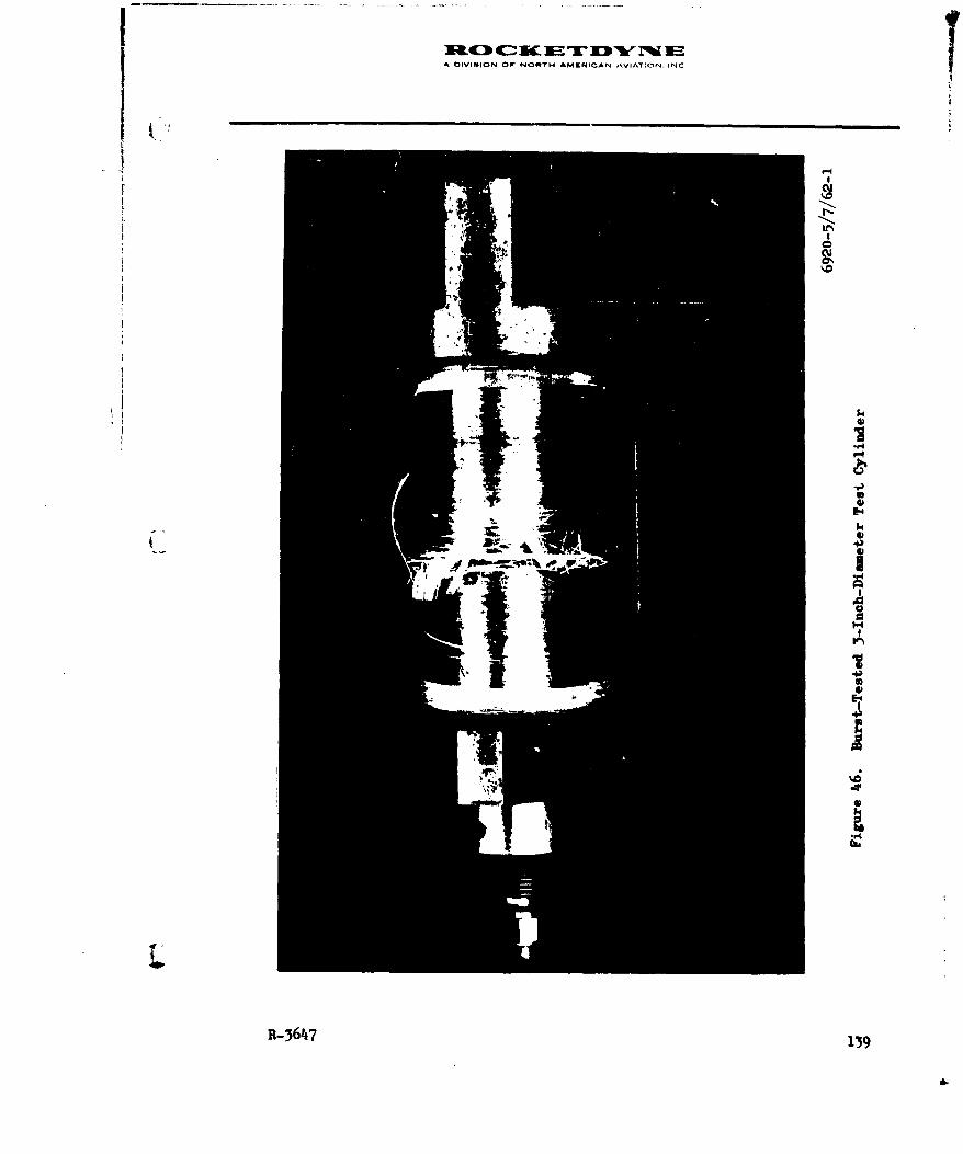
A DIVISI9ON OW NOT AMERICAN ATON N
(7,
R-3647 13
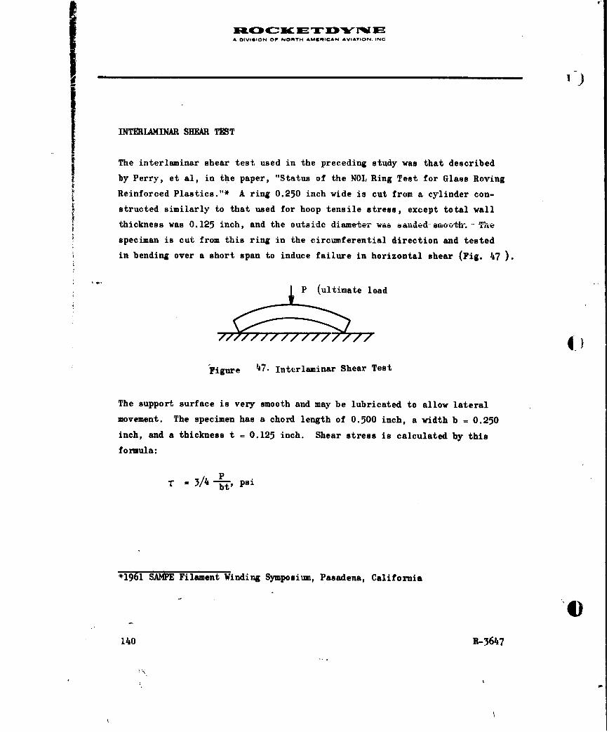
A DIVISION OF NORTH AMrNICAN AVIATION. INC
K,)
INTERLAMINAR SHEAR TEST
The interlaminar shear test used in the preceding study was that described
by Perry, et al, in the paper, "Status of the NOL Ring Test for Glass Roving
Reinforced Plastics."* A ring 0.250 inch wide is cut from a cylinder con-
structed similarly to that used for hoop tensile stress, except total wall
thickness was 0.125 inch, and the outs-ide--diam-eter vi 6anded-synooth - The
speciman is cut from this ring in the circumferential direction and tested
in bending over a short span to induce failure in horizontal shear (Fig. 47 ).
P (ultimate load
Figure 47. Interlaminar Shear Test
The support surface is very smooth and may be lubricated to allow lateral
movement. The specimen has a chord length of 0.500 inch, a width b f 0.250
inch, and a thickness t = 0.125 inch. Shear stress is calculated by this
formula:
T IS3/4 -, psi
*1961 SAMPE Filament Winding Symposium, Pasadena, California
140 R-3647
'-I
A DIVISION OP NORTi, AVARICAN AVIATION, INCL
GENERAL PROCESS SPECIFICATION FOR USE OF PREIMPREGNATEI) ROVING
1. INTRODUCTION
1.1 SCOPE
This specification describes the materials and processes used
in the filament winding of high-strength, lightweight pressure
vessels, rocket motor cases, etc., using continuous fiberglass
filament preimpregnated with epoxy resin.
1.2 CLASSIFICATION
Structures are of types requiring close dimensional tolerances,
laminate uniformity, and high performance reliability.
1.3 LIMITATIONS
Parameters and rekuirements herein are based on data developed
for one particular epoxy resin-preimpregnated glass filament
system and are not necessarily applicable to all systems.
2. APPLICABLE MATEPIALS AND SPECIFICATIONS
2.1 MATERIALS, PRODUCTIVE:
Material
Fiberglass Roving, 20 end, E-801, U. S. Polymeric Chemicals,
Preimpregnated with Epoxy Resin E787 Inc.
Santa Ana, California(Appenditk 151 )
4W
R-3647 141
I t HWY I.58
A VISION OF NONT1 ANsAICAf I AVAYIo INcW.
Fiberglass Roving, 20 end, U. S. Polymeric Chemicals, Inc.
E-HTS, Preimpregnated with Epoxy Santa Ana, California
Resin E787 (Appendix, 151 )
3. STORAGE OF MATERIALS
3.1 Spools of preimpregnated roving shall be kept in the original, or
equivalent, sealed bag or envelope and protective container in
such a manner as to prevent contamination or damage of the
material.
3.2 Material shall be stored prior to use at the following temper-
atures for the period of time specified.
Temperature, maximum, F Time, maximum 4)80 72 hours
40. 6 weeks
0 12 weeks
Storage time shall be determined from the date of impregnation.
Times at different temperatures shall not be accumulative. That
is, for example, material that has been stored for 10. weeks at
0 F may not be subsequently stored for 6 weeks at 40 F without
requalification. For determination of maximum allowable accumu-
lative storage time, the following table of equivalents may
be used:
24 hours at 80 F =I week at 40 F 3 2 weeks at 0 F
142 R-3647
FORM 808-B PLATE REV. 1-58
A DIVISION Op NORTH AMERICAN AVIATION. INC.
j 3.3 After storage for the maximum period of time as determined in
3.2, material shall be tested for compliance with the require-
ments of the material specification for preimpregnated roving.
3.3.1 Requalified material will be subject to qualification testing
at the end of 3 weeks when stored at 40 F, and 6 weeks when
stored at 0 F.
3.3.2 Material meeting the test requirements must be used immediately.
3.3 Lots of material placed in storage shall be removed on a first-
in, first-out basis.
3.4 Material that has been removed from cold storage shall remain
in the sealed protective cover until reaching room temperature
before being used.
4. MACHINE COMPONENTS
4.1 DELIVERY PULLEYS
4.1.1 Pulley wheels used to support the roving band between the
package and mandrel shall be as large as possible, preferably
no less than 1.5 inches diameter.
4.1.2 The number of pulleys in contact with the roving shall be as
few as possible, preferably less than eight, and the area of
contact that the roving makes with the pulleys shall be less
than 180 degrees.
R-3647 143
FORM B00,0 PLATZ RCV. 1-9S

SDIVIDION OF 04ORT04 AMEMISPAN ^ViATIOW. IN
4.1.3 Pulleys shall have a nonsticky contact surface and shall rotate
freely., To meet these requirements, they shall be constructed
of nylon or Teflon (or Teflon-coated metal) sleeves firmly
attached to a ball bearing mounted firmly on a fixed metal stud
or shaft.
4.1.4 The first delivery pulley contacted by the roving shall be
located from the surface of the spool at a minimum distance
equivalent to the length of the package. This measurement shall
be made normal to the axis of spool. Guide rollers with axis
mounted normal to the axis of the package shall be used between
the spool and first pulley immediately adjacent to the pulley.
4.2 TENSIONING DEVICES
4.2.1 Tension control devices shall be capable of maintaining a tension
on the strand within a tolerance of +5 percent of the nominal
setting at all rates of roving feed velocity.
4.2.2 The surface of brake rolls contacted by the roving shall be
relatively nonslippery and not subject to corrosion that may
harm or contaminate the roving.
4,3 All pulley wheels, and other surfaces, contacted by the roving
shall be kept free from transposed resin and any foreign mater-
ials that may contaminate or harm the roving strand. Pulley
wheels, and other devices, contacted by the roving shall be
replaced when the surface of contact becomes rough or distorted
so as to possibly cause harm to the roving strand.
1.44 R-3647
FORM OOB-B PLATE REV. 1.58

A DIVISION OP NORTH AMIRICAN AVIATION. IND.
'S
5. MANDRELS
5.1 Mandrels may be constructed of materials such as plaster, water-
Vsoluble salts, high-temperature melting salts, all metal, or
combinations of metal and other materials. They shall be dimen-
Fsionally stable, strong enough to support the applied winding
loads, and entirely satisfactory for the purpose intended.
5.2 The mandrel surface shall be covered with a mold release that
will allow easy separation of the mandrel from the filament-
wound structure. In the case of mandrels made from plaster or
other water-containing materials, the mandrel surface shall be
covered with a nonpermeable sealant film prior to application
of the mold release. Mold release and sealant materials shall
have adequate resistance to cure temperature, and shall be
entirely compatible with the materials in contact with them.
6. WRAPPING OPERATION
6.1 The mandrel shall be installed in the winding machine within
the limits specified for axial alignment and concentricity during
rotation. All other aspects of mandrel location and alignment
shall be checked for compliance with detailed instructions.
6.2 Preimpregnated roving strand(s) shall be threaded over the
appropriate brake and delivery pulleys without twists. During
the winding operation, twsts shall be removed from the
strand(s) when their existence results in the introduction of
twisted strands into the filament-wound laminate.
R -3647 145
rORM 600.3 PLATE REV. 1.58
A DIV8I1iM OP NORTH AMCRICAN AVIATION, IN.
6.3 The last delivery pulley or guide contacted by the roving prior
to wrapping on the mandrel shall be placed as close as practical
to the mandrel, or at the distance required by the detailed
instructions for the part being fabricated.
6.4 Tension on the strand(s) shall be measured between the last pul-
ley or guide contacted by the roving and the mandrel. Tension
of the strand(s) shall be measured while the strand is moving
at the velocity of the actual winding operation, using a Kidde
tensionmeter or similar device.
6.5 Tension shall be applied to the strand by a system of brake
rolls over which the strand traverses. The total tension
shall be 18 ± 2 pounds for each 20-end strand, unless specified
otherwise. A maximum of 15 percent of the total tension shall be 4 )
applied at the spool by resisting the rotation of the package.
The total tension shall be monitored throughout the winding
operation, or checked periodically with a device capable of
making measurements on the moving strand.
6.6 Before and periodically during winding, the turns per inch being
applied by the machine shall be checked for compliance with
detailed requirements.
6.7 Restarts in the midst of the winding operation necessitated by
breaks in the strand, runout of a spool of material, or breakdown
of the winding equipment shall be accomplished as follows:
a. The strand, while under tension, shall be cut close to
the mandrel and the cut end firmly pressed against the
146 R-%47
FORM 608.B PLATE REV. 1.58

A CiVImION OP NOAT64 AME|RIAN AVIATION. IN0C
mandrel or previously applied wrappings. The cut shall be
made in a location that will have the least effect upon the
strength of the fabricated item. For example, longitudinal
filaments shall be cut in the cylindrical area of a pressure
vessel or motor case.
b. Restart shall be made by placing windings over two or three
turns of the previously applied wrappings of the same layer.
After progressing a minimum of three turns past the stopping
point, the excess (overlapping) windingi ohall be carefully
peeled off.
c. Where multiple strands are used and a break occurs in one
strand, the new strand may be attached to the unbroken strand.
at the end of the broken strand so as to allow the new strand
2 to be carried to the mandrel. The new strand shall be
attached by pressing it to the unbroken strand over a contact
length of 12 inches at a convenient location along the roving
delivery system of the machine. Adhesion of the strands may be
implemented by use of a roller device to obtain greater contact
pressure and heat from a hot air gun. No more than one strand
at a time may be so attached.
CAUTION: Roving shall not be heated above 125 F.
6.8 Winding will be performed at room temperature unless specified
otherwise. Where it is desirable, or necessary, to preheat the
roving, it shall be heated to a maximum temperature of 125 F. Heat
shall be applied to the strand as close to the mandrel as possible.
4W
R-3647 147
FORM 6O6l PLATE REV. 1.56

A OIVISION OF NORT64 AVAMIOAN AVIATION. IN.
I!6.9 Heat may be applied to localized areas on the wrapping during
the winding operation in order to soften the roving and facili-
tate laydown as it is being wound around bosses, to increase
tackiness in order to improve adhesion and reduce slippage where
necessary, or for other requirements to facilitate winding.
CAUTION: Roving shall not be heated above 125 F.
6.10 Visual inspection shall be maintained during the winding opera-
tion of each spool of preimpregnated roving. Use of the spool
shall be terminated and the spool replaced by a new one when
the presence of any of the following defects becomes excessive
and threatens to degrade the quality of the part being fabricated.
a. Bandwidth outside of tolerance
b. Nonuniform impregnation, as indicated by dry roving
c. Fuzziness of the strand
d. Nests and knots in the strand
e. Twists in the strand
f. Folds parallel to the fibers (apt to occur in wide-band
material).
7. CURING PROCEDURE
7.1 Cure schedule shall be that specified for the material used.
Temperatures shall be measured by thermocouples attached to the
coldest portion of the resin-glass structure. An autographic
record of time-temperature relationship shall be made for each
part.
I)
148 R-3647
FORM OB88 PLATE REV, t.5B
A avieloN OP NA714 AM|qICAN4 AVIATION. IN
7.2 External pressure applied to the filament-wound laminate by the
use of a vacuum bag or shrink tape may be used only when required
by the detailed specification for a specific part.I
7.3 Parts shall not be cured in an oven previously used to cure mater-
ials that may contaminate the part.
8. FINISHING OF PARTS
8.1 No sanding, machining, or blasting operations may be performed on
plastic materials in areas of structures subjected to internal
pressurization, except as noted on applicable drawings.
8.2 All finishing operations shall be performed according to appli-
cable specifications or drawings only.
9. REPAIRS
9.1 No repairs may be made to primary structures After cure,except as
approved by Material Review Board.
9.2 Defects in uncured laminates may be repaired by removing the de-
fective material and reperforming the applicable winding operation.
Removal of defective material shall be performed so as not to
cause damage to the remaining material.
9.3 Repairs shall be performed only upon the approval of and under the
supervision of the Quality Control Department.
R-3647 149
FORM 00o8 PLATE RV. 1.58

A DIVISION oP HNOT6 AK49MICAN AVIATION. INC.
10. QUALITY CONTROL
10.1 INSPECTION
10o1.1 Parts shall be inspected to the dimensional requiremeits of the
drawings.
10lo2 Cured parts shall be inspected for defects that would affect the
structural integrity of the part.
10.1.3 In-process inspection shall be performed according to the require-
ments of the detailed fabrication specification for specific
parts and the requirements of this specification.
10.2 Where necessary for closer control of the roving, and for a 4more complete history of the material used in the part, each
package of material may be sampled and inspected. The tests re-
quired and the frequency of testing will be as specified by the
detailed requirements of each part.
150 R-3647
FORM 608.0 PLATE REV. 1.5B

A DIVIGION OP NORI4T0 AVIURICAN AVIATION. iNC
MATERIAL SPECIFICATION FOR GLASS ROVING, EPOXY RESIN IMPREGNATED, UNCURED
I
1. SCOPE
This specification establishes the requirements for three types of
continuous glass filament roving impregnated with a B-stage, heat-
curing, epoxy resin system suitable for filament winding.
1.1 CLASSIFICATION
1.1.1 Types
The impregnated roving shall be of the following types, as
specified:
Type I General purpose
Type II High tensile strength
Type III Very high tensile strength
1.1.2 Classes
The impregnated roving shall be of the following class unless
otherwise specified:
Class 20 20 end roving
2. APPLICABLE DOCUMENTS
None
4,*
R-3647 151
FORM 40l. PLATE REV. 1.50

A OSVISION OP NORN AKMNICAN AVIATION. INC.
3. REQUIREKENTS
3.1 MATERLLS
The finished preimpregnated roving shall consist exclusively of a
suitably finished fiber glass roving, a heat-curing, B-Stage,
epoxy resin system and a small amount of residual solvent. The
materials used shall be uniform in quality, free of foreign mater-
ials, diluents and contaminants, and shall be entirely suited to
the intended purpose.
3.1.1 Roving
The roving used shall be:
' )Type I. Low alkali, lime-alumina, borosilicate glass known com-
mercially as ECG l4O's, with a suitable, epoxy-compatible size.
Type II. Low alkali, lime-alumina, borosilicate glass known com-
mercially as ECG-140's, with a suitable, high-tensile-strength
epoxy-compatible size which is applied at the bushing.
Type III. Low alkali, magnesium aluninum siiicate glass of
improved tensile strength, with a suitable, high-tensile-strength
epoxy compatible size which is applied at the bushing.
The required number of ends, as specified by the class number,
shall be gathered without twist. The end count shall be as
specified ± 0 ends.
152 R-3647
FORM 608B. PLATE REV. 1.58

A DiV1i6OP Or iMT AMfRaCAN AVIATION. INC.
3.1.2 Resin System
The resin system used shall be an epoxy resin system suitable for
preimpregnation and B staging. The curing system selected shall
be capable of being cured and postcured at temperatures not in
excess of 350 F for periods of time not in excess of 6 hours.
High boiling, reactive or nonreactive diluents or extenders shall
not be used.
3.1.3 Resin Content
Unless otherwise specified the nominal resin content shall be
20 percent.
3.2 PHYSICAL PROPERTIES
The preimpregnated roving shall meet the physical property re-
quirements of Table 16 when tested by the methods indicated.
f0
R-3647 153
FORM SOS.E PLATE REV. 1.5l

A alIsION or NORTH1 ApUm~0AN AVIATION. INO.
1-41
-vI4) - 9 gi
00
&4 0 r r 0
4) 04 0
12 0
r-4 t' d-
0 14
E-4 dp 0
m-4 E-4~ 14
93N
0 42
E-4 IV0
0 cdw. .4 Wa E- E4 0 4
AD -+2 14 0~ 4Wm t -.- 4~ tel U) U)
C 4 +10 w r- W V -40 .
Q ;. 0 m I I4Ibo.H9 3 0 E-P -4 P-)0t'44) .= WU H- -- 4$ed0 4 4 ) 411
154 R-36470 4
FOR 008- PLAT REV 1-58U ~

A OIVII60 *oP NONTN A MIRNIAN AVIATION. INO.
3.3 BANDWIDTH
The roving shall meet the bandwidth requirement of Table 16 andshall be a single web of roving without splits or separations.
3.4 KNOTTING AND SPLICING
There will be noknots or splices introduced during the resin
impregnation process.
3.5 WORKMANSHIP
Roving submitted for qualification or acceptance under this
specification shall be of the highest quality of workmanship and
shall be free of manufacturing defects which would adversely
affect the performance of the finished roving. Visible indica-
tions of dry streaks or other evidences of poor impregnation
shall be cause for rejection.
3.6 SHELF LIFE
The preimpregnated roving shall meet all of the requirements of
this specification following storage for 6 months .when shipped
and stored at temperatures not exceeding 0 F.
3.7 The roving shall be capable of being unwound easily and rapidly
under a tension equivalent to 4 ± 0.4 pounds per 20-end strand
and shall show no tendency to dig into the ball or to leave loose
ends or strands.
R-3647 155
FORM OB.3 PLATE REV. f-B
A CIVI|iON Or NORTH AMKERICAN AVIATION, INC.
t
3.8 QUALITY ASSURANCE
3.8.1 Qualification Tests
The qualification tests shall consist of all of the tests of
this specification conducted on a sample which is entirely re-
presentative of the properties and packaging of the material
to be offered for purchase to the requirements of this
specification.
3.8.2 Material and Process Changes
Following approval of a supplier's qualification sample the
supplier shall make no changes in the materials or processes
used in the manufacture of the impregnated glass roving without 4 _
prior approval of the purchaser. Material or process changes
may require requalification of the material or other evidence
of acceptability at the option of the purchaser.
3.8.3 Lot
A lot of impregnated glass roving shall consist of not more
than one lot of unimpregnated glass roving, impregnated in a
single, continuous operation with a single batch of resin and
offered for inspection at one time.
3.8.4 Certification
Each lot of impregnated glass roving offered for inspection shall
be accompanied by the manufacturer's certification that the glass,
156 R-3647
FORM 60.S PLATE REV. 1.-5

A 0VISION OP NORTH AVA906AN AVIATION. INC.
resin system, and processing used in the manufacture of the
material being submitted are identical in every way to the
glass, resin system, and processing used in the manufacture of
the supplier's qualification sample.
3.8.5 Lot Acceptance Testst
Lot acceptance tests shall consist of any or all of the tests
of this specification at the option of the purchaser. The
frequency of the performance of any of the tests and any
sampling plans shall be determined by the Rocketdyne Quality
Control Department. Any defects which were not detectable
during lot acceptance testing and which became apparent during
the subsequent use of the material shall be cause for rejection
of the unused portion of the ball, provided that such defects
are cause for rejection under the requirements of this speci-
fication and are not a result of mishandling, improper storage,
or expiration of shelf life.
4. METHODS OF TEST
4.1 SAMPLING PROCEDUBES
4.1.1 For Hoop Tensile and Shear Strength Tests
The sealed package shall be removed from the storage environment
and shall be allowed to come to room-temperature condition. The
package shall then be opened, and, after removing and discarding
the first three way winds, the material shall be wound directly
4
R-3647 157
FORM 80O0 PLATE REV. 1.50

A v1.e0o OF 4ORYN AVURICAN AYVTION. INC.
from the sample roll onto the appropriate mandrel to prepare
the test specimens. The sample roll shall then be resealed in
the original container and returned to the storage environment.
4.1.2 Other Specimens
While at the storage temperature, the package shall be opened
and, after removing and discarding the first three way winds,
sufficient material for the tests to be run shall be taken from
the roll. The samples shall be immediately sealed in moisture-
proof bags, identified, and allowed to come to room-temperature
conditions. The roll shall then be resealed in the original
container. The samples shall be tested within 8 hours after
oeing taken from the roll. If such sampling results in damage
to the material, all sampling shall be conducted in accordance 4with paragraph 4.1.1.
4.1.3 Storage Records
Records shall be maintained of the periods that any roll has
been out of storage environment.
4.2 TEST PROCEDURES
The following test procedures shall be used:
4.2.1 Volatile Content
Three samples, each 36 inches ± 0.1 inch long, shall be weighed
to the nearest milligram. The loosely coiled specimens shall be
158 R-3647
FORM 609.2 PLATE REV. 1.8
A VIIION OP NONT1 AEMCAN AVIATION. Itt.
dried for 15±1 minutes in a circulating air oven maintained at
225±10 F. Each of the specimens shall be removed from the oven,
cooled in a dessicator and reweighed to the nearest milligram.
Calculate the volatile content as follows:
Wo - WlVolatile Content,weight percent o 0 0
Where Wo - original weight in grams.
Wi - Weight of sample with volatile removed.
The average of the three values shall be reported.
4.2.2 Resin Content
The three samples used for volatile content shall be placed in
previously ignited, cooled, and weighed porcelain evaporating
dishes or crucible and shall be ignited for 60±10 minutes in a
furnace maintained at 1150±50 F. The samples shall be cooled in
a dessicator and reweighed to the nearest milligram. Calculate
the resin content as follows:
WI - W2 10
Resin Content,weight percent. W1 2X100
Where Wo = original weight in grams
W ='Weight of specimen with volatiles removed in grams
W2 = Weight of specimen after ignition in grams
The average of the three values shall be reported.
4r
R-3647 159
FORM 60-. PLATE RtV. 1.
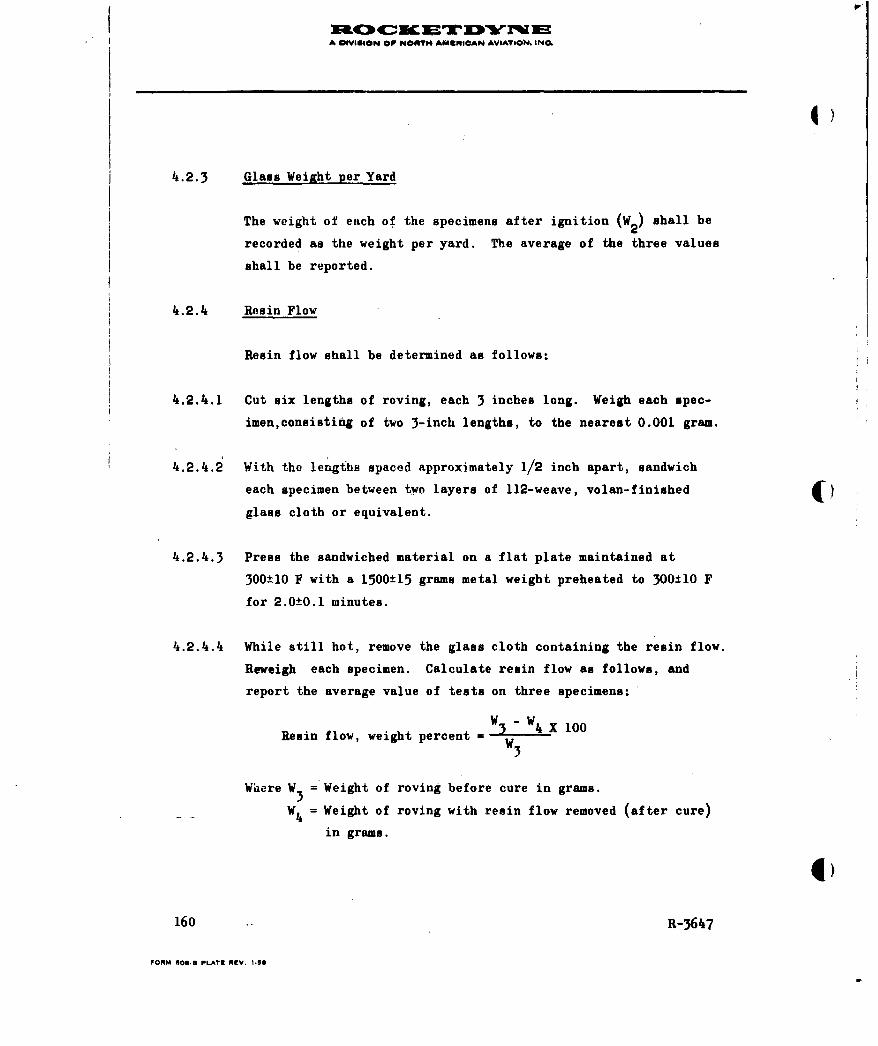
A NVIGION OP NORTH AMWIRICAN AVIATION. INC.
4.2.3 Glass Weixht per Yard
The weight of each of the specimens after ignition (W2) shall be
recorded as the weight per yard. The average of the three values
shall be reported.
4.2.4 Resin Flow
Resin flow shall be determined as follows:
4.2.4.1 Cut six lengths of roving, each 3 inches long. Weigh each spec-
imen,consisting of two 3-inch lengths, to the nearest 0.001 gram.
4.2.4.2 With the lengths spaced approximately 1/2 inch apart, sandwich
each specimen between two layers of 112-weave, volan-finished ()glass cloth or equivalent.
4.2.-4.3 Press the sandwiched material on a flat plate maintained at
300±10 F with a 1500±15 grams metal weight preheated to 300±10 F
for 2.0±0.1 minutes.
4.2.4.4 While still hot, remove the glass cloth containing the resin flow.
Reweigh each specimen. Calculate resin flow as follows, and
report the average value of tests on three specimens:
Resin flow, weight percent Ww3
Where W3 = Weight of roving before cure in grams.
W 4 = Weight of roving with resin flow removed (after cure)
in grams.
160 R-3647
FORM 608E PLATE REV. 1.8

A IVIGION OF NOSIT" AMErACI^N AVIATION. iNC.
4.2.5 Tackiness
Two strands of roving shall be placed on the horizontal track of
the tackiness test fixture shown in Fig. 20 . The roving strand
,and the fixture shall be at 75 to 80 F at the time of test. The
roving strands shall be placed 0.375 inches from the apex of
the "V" and shall be held under a tension equivalent to 4±0.,A
pounds per 20-end strand. A polished steel ball 0.750 inches in
diameter shall be thoroughly cleaned in acetone and shall be
placed on the inclined ramp at a distance of 8±0.1 inches from
the intersection with the horizontal ramp. The ball shall be
released cleanly and allowed to roll to a stop along the roving
strands. The distance of roll along the horizontal ramp shall
be measured to the nearest 0.1 inch. Using the same roving
K_ sample, the test shall be repeated five more times. The initial
value shall be discarded and the average of the remaining five
values shall be reported ap the tackiness.
4.2.6 Bandwidth
A single sample not less than 6 feet long shall be laid flat
under nominal tension of 0.5 pound per end. The bandwidth shall
be measured to the nearest 0.001 inch in at least five places
not less than 12 inches apart, using a vernier caliper. The
average for the five values shall be reported.
4.2.7 Strand Tensile Strength
Ten samples approximately 24 inches long shall be tested within
8 hours after being removed from the roll. The test shall be
R-3647 161
FORM O000 PLATE REV. ,ifS
A 4VIgsoN Op N Ol*fT ANMEIoAN AVIATION. ING
run on a testing machine using a crosshead speed of 1.0 in./min,
using spool-type grips and a load weighing scale which is not
more than 10 times the expected breaking strength. The grips
shall be positioned so that the center-to-center distance is
6±0.25 inches. The sample shall be secured, wrapped around one
spool grip at least onc full turn, wrapped around the second
grip at least one full turn, and the remaining end secured.
The crosshead may then be adjusted to a preload of not more than
10 pounds,if desired. The crosshead shall then be operated
automatically until the maximum load has been reached. The
maximum load shall be recorded, and the average of the 10 val-
ues shall be reported.
4.2.8 Hoop Tensile Strength
4.2.8.1 Sample Preparation.
4.2.8.1.1 The samples shall be of the dimensions shown in Fig. 44.
They shall be wound on suitably coated mandrels using a mach-
ine having the necessary tensioning, traversing, and speed
controls.
4.2.8.1.2 The samples shall be formed by first winding a 0.030-inch-thick
layer of roving in a circumferential pattern. During the wind-
ing the roving shall be maintained under a tension of 1±0.1
pounds per end. The traverse and circumferential speeds shall
be selected so that, using a single strand of 20-end roving,
each turn is placed so that there are 15±0.5 turns per inch and
so that the mandrel is completely coverr-t on each pass. The
roving and the mandrel shall be at a temperature which is not
higher than room temperature during the winding.
162 R-3647
FORM 606.5 PLATE REV. 1-56
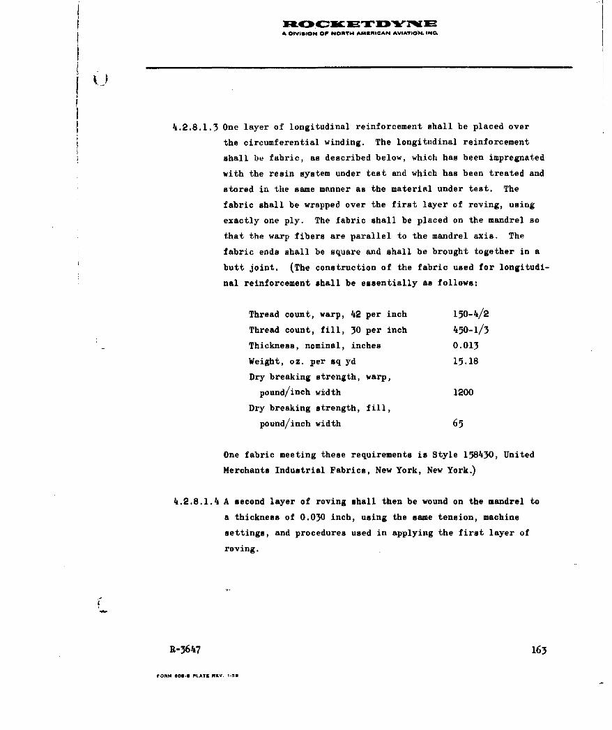
A IVISION Op NORTH A^1IURICAN AVIATION. iNO
4.2.8.1.3 One layer of longitudinal reinforcement shall. be placed over
the circumferential winding. The longitudinal reinforcement
shall be fabric, as described below, which has been impregnated
with the resin system under test and which has been treated and
stored in the same manner as the material under test. The
fabric shall be wrapped over the first layer of roving, using
exactly one ply. The fabric shall be placed on the mandrel so
that the warp fibers are parallel to the mandrel axis. The
fabric ends shall be square and shall be brought together in a
butt joint. (The construction of the fabric used for longitudi-
nal reinforcement shall be essentially as follows:
Thread count, warp, 42 per inch 150-4/2
Thread count, fill, 30 per inch 450-1/3
Thickness, nominal, inches 0.013
Weight, oz. per sq yd 15.18
Dry breaking strength, warp,
pound/inch width 1200
Dry breaking strength, fill,
pound/inch width 65
One fabric meeting these requirements is Style 158430, United
Merchants Industrial Fabrics, New York, New York.)
4.2.8.1.4 A second layer of roving shall then be wound on the mandrel to
a thickness of 0.030 inch, using the same tension, machine
settings, and procedures used in applying the first layer of
roving.
R-3647 163
FORM 009.0 PLATZ RKV- 1.58
A IVISION OF ORT4 AKUNICAN AVATYION. IN
4 )
4.2.8.1.5 The additional thickness at each end of the cylinder, as
Fig.44 shows, shall be provided by additional circumferential
windings applied to the basic structure, using essentially the
same procedures used in the prior winding.
4.2.8.1.6 The sample shall be cured in a curculating-air oven, using the
following cure cycle:
1 ± 0.1 hours at 250 ± 10 F
followed by
6 ± 0.1 hours at 350 ± 10 F
The temperature shall be increased from 250 to 350 F in not
more than 0.5 hour. The oven temperature shall be automatically
recorded. Following the cure cycle, the cylinder shall be (I
removed from the mandrel. The central 3-inch portion of the
sample shall not be machined or finished if any way, and extreme
care shall be exercised to avoid damage to the fibers.
4.2.8.2 Test Procedure
4.2.8.2.1 Three cylinders shall be tested at room temperature by hydro-
static burst, using a test fixture essentially in accordance
with that shown in Fig. 3. The fixture shall be designed so as
to preclude the application of endwise loads or stress con-
centrations to the sample.
4.2.8.2.2 Prior to testing, the minimum wall thickness of the sample shall
be determined, using micrometers having spherically shaped
anvils. At least four equally spaced measurements shall be
4)
164 R-3647
FORM 6083 PLATE RKV. 1-58
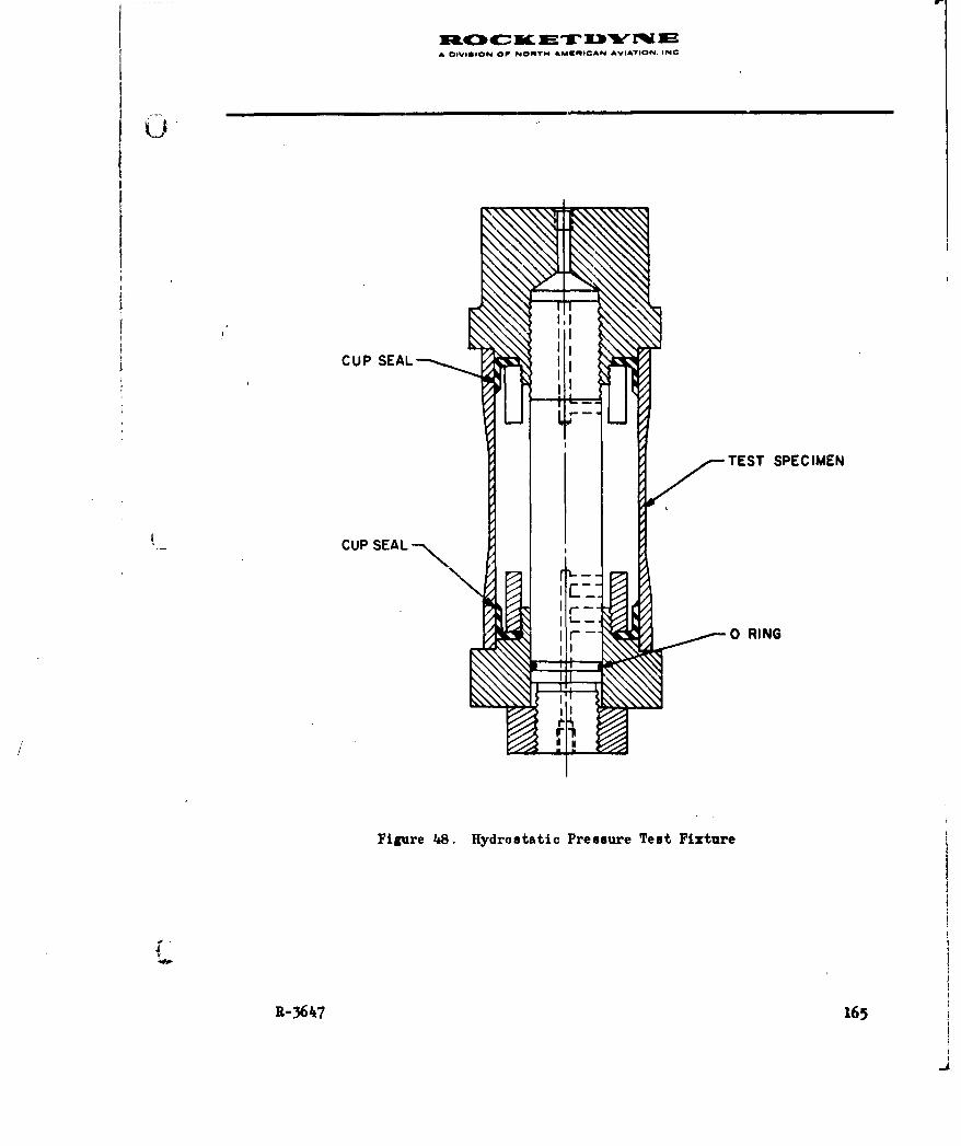
I A OSVSUSON OF 04NTY 4AMRR*CAN AVIATION. INC
TEST SPECIMEN
I rr -0 RING
Figure 1i8. Hydrostatic Pressure Test Fixture
R-3647 165
A DIVI&ION OP NORTh AMERICAN AVIATION. INC
made. The thickness measurements shall be made to the nearest
0.001 inch and shall include any surface resin. All thickness
shall be recorded.
4.2.8.2.3 A nonpermeable, flexible, low-strength sleeve of the proper
size (latex rubber is suitable) shall be placed in the specimen
which shall then be placed on the fixture and filled with
water at room temperature.
CAUTION: Extreme care must be taken to ensure that all air
is expelled from the cylinder before pressurizing.
4.2.8.2.4 The hydrostatic pressure shall be applied and increased at a
steady rate of 300 psi/sec, without shock loading, until
failure occurs. The hydrostatic pressure at failure shall be (measured and recorded.
4.2.8.2.5 The thickness of the layer of longitudinal fibers shall be
measured on the exposed material in the broken specimen.
Measurements shall be made to the nearest 0.001 inch.
4.2.8.2.6 The hoop tensile strength shall be calculated as follows:
S t = Pd2t
n
Where St a Unidirectional tensile stress at burst, psi
P = Hydrostatic pressure at burst, psi
d = Mean diameter of specimen, in. = 3 + tt
tt = Minimum total wall thickness, inches
tf = Fabric thickness, inches
t = Net wall thickness, inches = tt - tf
166 R-3647
FORM 60-rn PLATE RIEV. 1.58
A 0IVGN OF NORT AKtgIOAPA &VIATION. INCL
All values shall be reported. However, retests shall be made
t for any specimens which break at some obvious, fortuitous
flaw, or for any specimens which fail outside of the central,
uniform-cross-section portion of the specimen. The report shall
include the average value for all valid tests.
4.2.9 Interlaminar Shear Strenfth
4.2.9.1 Sample Preparation. The samples shall be cut from a wound ring
as shown in Fig. 48 and shall be of the dimensions shown in
7Fig. 49. The rings shall be wound on a suitably coated mandrel
using the conditions specified in paragraph 4.2.8.1.2 except
that the thickness of the ring shall be .250 ± .010 inches.
The ring shall be cured in accordance with the cycle specified
in paragraph 4.2.8.1.6.
4.2.9.2 Test Procedure. The room-temperature, interlaminar shear
strength test shall be as follows:
4.2.9.2.1 Five samples shall be tested in a test setup which shall be
essentially that shown in Fig. 50. The specimen shall be aligned
so that its midpoint is centered under the loading nose and its
long axis is perpendicular to the axis of the loading nose.
4.2.9.2.2 Before testing the thickness and width of each specimen shall
be measured to the nearest 0.001 inch.
4.2.9.2.3 The specimens shall be loaded to failure in a calibrated test-
ing machine at a crosshead speed of 0.05 in./min. Failure is
characterized by an audible snap accompanied by a sharp drop
-" in load.
R-3647 167
FORM S01l1 PLATE REV. 1.50

A DIVI~SION OF NOWTM AMERICAN AVI4ATION INC
~Kw
Do
t
Do 6.000±0.002Do 5.750±0.002
t 0. 25 0 ±0.003
W 0.250 0O.000
Figure 49. Ring Specimen
168 R-3647
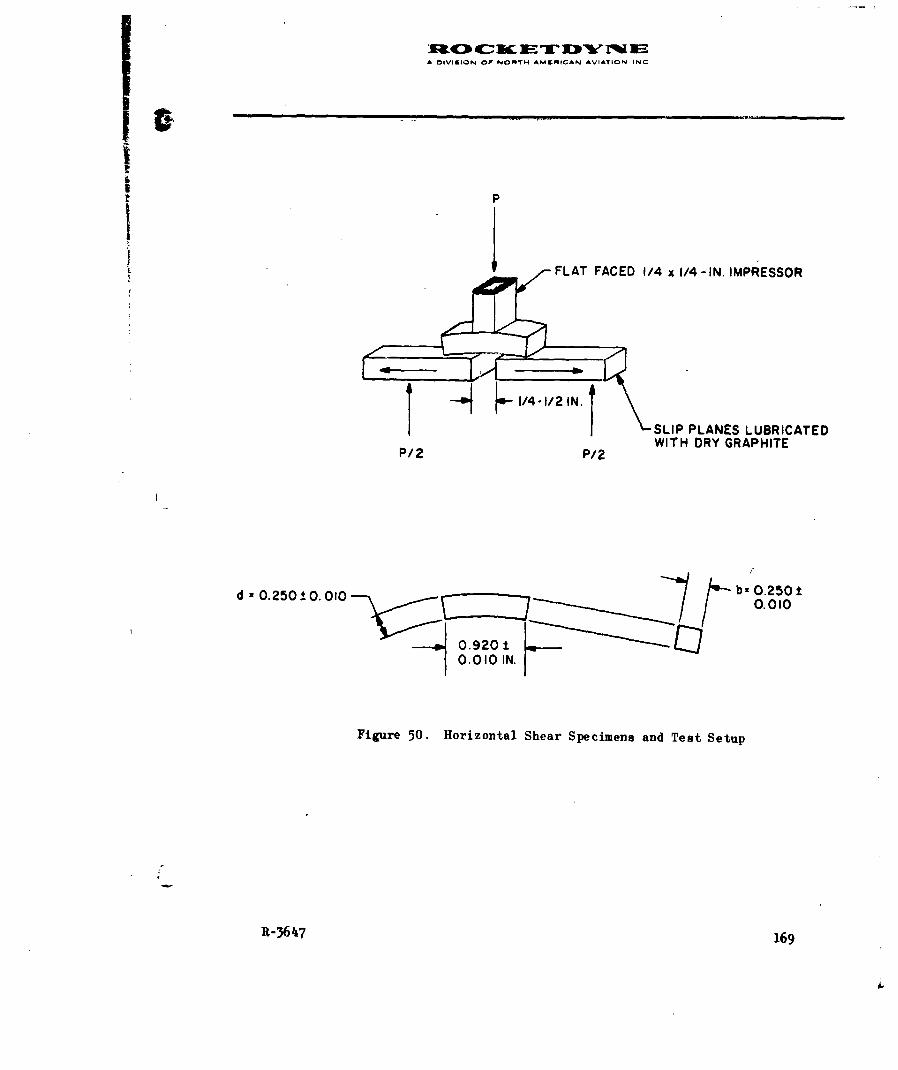
A DIVISION Of NOftTH AMCMICAN AVIATION INC
FLAT FACED 1/4 x1/4 -IN. IMPRESSOR
I -~j.-I4.I/1N. 1 SLIP PLANES LUBRICATEDP/2 P/2 WITH DRY GRAPHITE
d :0.250±0. 010 E7III ~bz0.250
H 0.9201±1110.010 IN .
Figure 50. Horizontal Shear Specimens and Test Setup
R-364~7 169
A b yVmIN O F NOT AMgICAN AVIATIOW, eN.
4.2.9.2.4 The interlaminar shear strength shall be calculated as follows:
s. =0.75PR is bt
Fhere
Sis = interlaminar shear stress at failure, psi
P = breaking load, pounds
b = width of specimen, inch
t = thickness of specimen, inch
All values shall be reported. Retests shall be made for any
specimens which break at some obvious, fortuitous flaw or
which fail in a manner other than shear. The report shall
include the average value for all valid tests.
4.2.9.3 The 300 F interlaminar shear strength test shall be as follows: 4)4.2.9.3.1 Five samples shall be tested in accordance with paragraph
4.2.9.2 except the entire fixture shall be enclosed in a test
chamber maintained at 300 ±'5 F. The samples shall be stabil-
ized at the test chamber temperature prior to testing. Because
of the low strength of the samples, and because of the muffling
effect of the test chamber, these samples may not fail with an
audible noise. The loading chart of the test machine should be
observed during the test. Failure is characterized by a "peak"
in the load-time curve. A "shoulder" in the curve followed by
further increase in load does not indicate failure. A pro-
nounced increase in load following a peak indicates that the
sample is undergoing compression.
170 R-3647
FORM 40.3 PLATE REV. 1.58
A DIVISION OP NORTN AMeRICAN AVIATION. INC.
4.2.9.4 The interlaminar shear strength test after water boil shall be
as follows:
4.2.9.4.1 Five samples shall be boiled in distilled water for 2.0 ± 0.1
hours. The samples shall then be transferred to room tempera-
ture distilled water and stored in water until tested. The
samples shall be tested in accordance with paragraph 4.2.9.2.
4.3 REINSPECTION
Twelve weeks after the lot acceptance tests, each lot of mater-
ial shall be retested for resin flow and for strand tensile
strength in accordance with the methods specified in paragraphs
4.2.4 and 4.2.7 of this specification. Materials which meets
the requirements of paragraph 3.2 shall be maintained in
storage. This procedure shall be repeated at 6-week intervals.
Material which fails to meet the requirements of paragraph
3.2 on the initial or subsequent retests shall be clearly
identified as unsatisfactory and shall not be used on deliver-
able items.
5. PACKAGING AND MARKING
5.1 PACKAGING
The roving shall be wound with a uniform tension on a cylin-
drical, heavy duty winding tube 10.9 ± 0.25 inches long, with
an inside diameter of 3 inches. The roving shall traverse
10.0 ± 0.25 inches of the tube length and shall be centered on
the tube. 'The roving shall be wound on the tube in a regular
R-3647 171
FORM OS.0 PLAT, REV. t.50

A DIVISION OP NORT0 AUUtICAN AVIATIOn. INCL
)
pattern which will permit rapid unwinding of the package on
automatic machinery without whipping, fraying or other damage
to the roving.
The outside end of the roving shall be secured to the package
with a strip of masking tape. A rigid pad shall be placed over
each end of the winding tube and pressfit tightly against the
winding tube. These pads shall have a minimum thickness of 1/8
inch and the diameter shall be at least 1/4 inch greater than the
outside diameter of the roll. Each roll shall be placed in a
polyethylene film having a thickness of 0.003 inch (commercial).
Each roll shall then be sealed in a flexible, moistureproof,
sealable bag. Unless otherwise specified in the purchase order
or contract, the nominal net weight of the spool shall be 15
pounds, and the minimum net weight of any one spool shall be 4)10 pounds.
5.1.1 The rolls shall be placed in a clean, dry container, as speci-
fied on the purchase order. The packing container shall be so
constructed as to ensure acceptance by common or other carrier
for safe transportation, at the lowest rate, to the place of
delivery specified by the purchase order of contract.
5.1.2 Shipping and Storage Environment
The material covered by this specification shall be shipped and
stored at temperatures not exceeding 0 F, except it may be sub-
jected to temporary storage at 40 F maximum for a period not to
exceed 48 hours. Records shall be kept on the individual con-
tainers, showing the number of hours any roll has been in tem-
porary storage or out of the specified storage environment.
172 R-3647
FORM 600. PLAT9 REV. t-58

A OIVIGION OP NO1T ANIICAN AVIATION. INC,
IIi ;
5.1.3 Delivery Date
Material which has been impregnated more than 30 days prior to
the delivery date shall be subject to rejection without re-
course to, and regardless of the results of, any lot accept-
ance tests.
5.2 MARKING
Marking shall include but not be limited to the following:
5.2.1 Winding Tube Identification
Each winding tube shall be clearly and permanently marked as
follows:
1. Number of this specification, including type and class
designation
2. Manufacturer's name and designation
3. Lot number of impregnated roving
4. Spool number
5. Date of impregnation
5.2.2 Package Marking
Individual roll containers shall be clearly and permanently
marked with the following information:
1. Number of this specification including type and class
designation.
R-3647 1.73
FORM 60.18 PLATE REV. 1,56
A OVISIO@ OP NOMfl4 AVAgIOAN AVIATION. INCO
2. Manufacturer's name and designation
3. Lot number of impregnated roving
4. Spool number
5. Date of impregnationA,
6. Net weight
7. Rocketdyne Purchase Order Number
5.2.3 Warnina MarkingH
Each roll container and the exterior packing shall be prom-
inently and permanently marked with a storage warning essenti-
ally worded as follows:
1. Temperature sensitive materials
2. Keep away from heat
3. Store at 0 F maximum
174 R-3647
rORM 008.5 PLATEI RZV. 1.58