ad-'?? 7s dam 26 siphon of pishkun supply canal ,26 pishkun supply canal .31 pishkun reservoir...
TRANSCRIPT
AD-'?? 7S
Technical Report No. l\.
AN INTEGRATED-SELECTIVE KEY FOR THE PHOTO IDENTIFICATION OF IRRIGATION STRUCTURES
OF A GRAVITY-FLOW IRRIGATION SYSTEM
By
Clyde F. Kohn
A Contract Between
Geography Branch, Earth Sciences Division Office of Naval Research, Navy Department
and
"Northwestern University
Project No. ONR 069-005 lontract No. N7 onr U5-005
Clyde F, Kohn, Director William E. Powers, Associate Director
Department of Geography The College of Liberal Arts
Northwestern University Evanston, Illinois
June, 1953

r
i
i
i i
TABLE OF CONTENTS
Introduction 1
The Greenfields Irrigation District 1+
Settlement of the Greenfields Irrigation District. ... 7
Irrigation Structures Associated with a Gravity- Plow Project 11
Layout of the Distribution Svsten .12
Drainage Ditches 16
Non-Irrigation Structures 17
Conclusions 16
Aerial Photo Identification of Structures Associated with the Greenfields Irrigation District:
Storage Facilities 19
The Gibson Dan 20
Gibson Reservoir ..... ... 22
Carriage System 25
Diversion Dam 26
Siphon of Pishkun Supply Canal ,26
pishkun Supply Canal .31
Pishkun Reservoir 33
Sun River Slope Canal 36
Distribution Features . 38
Genoral Characteristics 39
Greenfields Main Canal 1*2
Head Ditches kk
Border Ditches * kh

r
Aerial Photo Identification of Structures Associated with the Greenfields Irrigation District:
Distribution Features (continued)
Field Ditches kh
Turnouts . . , i+6
Check Dans h&
Special Structures I4.8
Miscellaneous Features 50
Drainage Ditches 55
li
r
LIST OF ILLUSTRATIONS
Figure 1 2 Areas of Irrigation Farming
Figure 2 3 Sun River Project
Photo 1 10 Aerial photo of irrigated end non-irrigsted l**nd
Photo 2 13 Aerial view of distribution features
Photo 3-A and 3-B 21 Stereogram of Gibson Dam
Photo k 21 Front view of Gibson Dam
Photo 5 23 Aerial photo of Gibson Reservoir
Photo 6-A and 6-B 2I4. Storeopair of view from north shore of Reservoir
Photo 7 2U View from north shore of Gibson Reservoir
Photo 8-A and 8-B 27 Stereogram of Diversion Dam
Photo 9 27 Diversion Dam
Photo 10 29 Siphon through which wnter is carried from south side of Sun River to north
Photo 11-A and 11-B 30 Stereogram of the siphon
Photo 12-A and 12-B 32 Stereogram of Pis.hkun Supply Canal, between Diversion Dam and Pi3hkun Reservoir
Photo 13-A and 13-B 32 Stereogram of Pishkun Supply Canal
ill

LIST OF ILLUSTRATIONS (CONTINUED)
Photo 1U 34 Aerial view of Pishkun Reservoir
Photo 15 35 Small dam along north sido of reservoir
photo 16-A and 16-B 35 Stereopair of earth-filled dam at the northeastern end of Pishkun Reservoir
Photo 17-A and 17-B 37 Stereogram of Sun River Slope Canal
Photo 18-A and 18-B 37 Stereopair of Sun River Slope Canal
Photo 19 41 General aerial view of a portion of the Greenfields Irrigation District showing distribution features
Photo 20-A and 20-B 43 Stereogram of the Greenfields Main Canal
Photo 21-A and a-B 43 Stereopair of Greenfields Main Canal
Photo 22 45 A head ditch along a highway
Photo 23 U5 Field ditches leading from a border ditch
Photo 24 47 A turnout from the Greenfields Main Canal
Photo 25 47 A radial check dam in the Greenfields Main Canal
Photo 26 I4.9 Ground appenrance of a turnout from a head ditch northward into a border ditch
Photo 27 49 A closeup of a cipoletti checkweir
Photo 28 51 A single drop
iv

r
LIST OF ILLUSTRATIONS (CONTINUED)
Photo 29 51 A series of drops
Photo 30-A and 30-B 52 Stereogram of a chute
Photo 31-A and 31-B 53 Stercopair of chute
Photo 32-A and 32-B Sk Stercopair of a wooden sluico
Photo 33-A and 33-B 5U Steroopair of a large galvanized conduit
Photo 3U-A and 3^-B 56 Stercogrnm of drainage ditch
Photo 35-A and 35-B 56 Stercopair of drainage ditch

I AN INTEGRATED-SELEC7IVE KEY FOR THE
PHOTO IDENTIFICATION OF IRRIGATION STRUCTURES OF A GRAVITv-FLOW IRRIGATION SYSTEM
Introduction
I
\
\
L
t
There are more than 200 million acre3 of irrigated land
in the world. About one-third of this lies in Pakistan and
India. Additional arena occur throughout the world. (See
Figure 1).
Water to irrigate these dry lands comes from three
principal sources: natural streams, underground reservoirs,
and surface reservoirs. Most modern larr;e-scEle projects now
depend on surface reservoirs to hold flood waters in check
until needed on the land for irrigation. Many such reservoirs
have been built in our west; others have been built or ore now
under construction in the African Sudan, India and Pakistan,
and in the semiarid regions of Russia. Water from the surface
reservoirs is carried in an elaborate system of canals by the
force of gravity to the lands to be Irrigated.
This kev is intended to provide the photo interpreter,
untrained in agricultural geography or land use economics, with
the means of identifying irrigation structures in an area char-
acterized by a gravity-flow irrigation system. The key has
been so arranged that fefjturcj within such a system can be
identified by reference to the appropriate portion of the key.
Because of this arrangemont, tlio key may be classified as an
Integrated-selectivo key.
-1-

-2-
1
Figure 1. Areas of Irrigation Farming. Outstanding examples of large gravity-flow Irrigation systems including dams, reservoirs, nnd canals outside tile United Stutes may be found in (A) the Murray River Valley of Australia; (5) the Upper Nile Valloy of the Anglo-Egyptian Sudan; (C) along the Niger River of French V/est Africa; (D) the Punjab area of North- western India and Pakistan; (E) along the Indus River of western Pakir.tan; and (F) along the Sir Dary°. and Amu-Darya Rivers of Russian Turkistan.
V
\
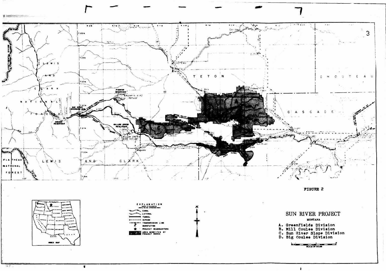
Studies were carried on in the Greenfields Irrigation
District, Fairfiold, Montana during 19'5l. (See Figure 2).
Photo interpretation of vertical stereopairs was integrated
with detailed field observations of gravity-flow irrigation
structures and associr-t^d fr.rm practices. Ground photographs
in stereopairs were taken of characteristic irrigation struc-
tures. The field studies were followed by office studies in
which photo oppearnnce of irrigation features was checked.
The key summarizes descriptions which help to identify
irrigation structures from aerial photographs in stereopairs.
1
r •§-||Blpw»< "7
PIOURE 2
--ti.iJ_l.f___, -r
h—j\ff..... fcr^J '•••... / ..!Vj i.— ——\ • "T—T~t i ._•••••• \ • I ' L-i L-1 v 'X""" i ••••!........ rr....»» •••V-f—f-H^A
|«.«M».| *«»-___»^-L
is-^-^i •. • • •x.
f X PL AN AT I 0 N
TWMCk —( • * * rmtrntrnttwo* LIM
* MfMT*TI«« ^ MMICI mwnmw
Mf« NHIIttD IT
SUN RIVER PROJECT MONTANA
A A. Greenfields Division B. Mill Coulee Division C. Sun River Slope Division D. Big Coulee Division

I
\
\
The Greenfields Irrigation District
The Greenfields Irrigation District of the Sun River
project, Fairfield, Montana, was selected as an area for
field study for four specific reasons, (1) The Project
receives water from the Lewis Range of the Reeky Moil?* tains
which lies about hS niles to the west. The general eastward
slope of the land makes irrigation possible by gravity-flow;
hence the Sun River project has within it those structures
which are common to gravitv-flow irrigation systems throughout
the world. (?.) The Sin River Project is one of the oldest
of the federal reclamation projects in the United States.
Construction on the Greenfields Branch was benun in 1913 and
was largely completed by 19?5» No new irrigation development
is contemplated. Thus, the District has probably attained its
maximum physical extent, although much remains to be developed
within the aroa to insure maximum efficiency of operation and
return for the money invested. (3) The project is a single-
purpose project. As a study it provides none of the complica-
tions of multi-purpose developments, and is ?\cre representative
of the kind of gravity-flow irrigation projects which have
been developed elsewhere in the v.*orld. (l\) The Px'oject is
3mall enough tc be understood in its entirety; yet large enough
to be representative of its kind.
The Greenfields Irrigation District is located about
thirty-five miles west of Great palls, Montana, between the
Sun River and Muddy Creek. Altogether the District occupies

r i i
(
I
1
i
\
!
about 90,000 acres of irrigable land on three distinct bench
levels. Each of these levels '.s bounded by abrupt scarps.
The source of water for the District is r,he Gibson
Reservoir which contair.3 the impounded waters of the Sun River.
The Gibson Dam wns put into operation in 1929. Water is
delivered the entire distance from the Gibson Dam by gravity
flow. The distribution system for water on the project consists
of 169.8 miles of canals and conduits, L1I4.I.9 miles of laterals,
and 190 miles of drains.
The Grc-cnfields Irrigation District of the Sun River
Project lies wholly north of the Sun River on a series of
benches, the lowest of which stands at approximately 3500
feet and the highest at I4.3OO feet above sen level. Although
the entire District is served by the same main supply canal,
within it are four distinct and separate divisions (Figure 2).
Two of these divisions, comprising 70,000 acres of irrigable
land, are the largest and most important parts of the Green-
fields Irrigation District. They 9ro bounded on the west by
Big Coulee and Greo^nfiolds f.ako and on the north by Muddy Creek.
These two units arc known as the GroonfioJds Division and the
Mill Coulee Division. The third unit, The Sun River Slope
Division, lie3 in a narrow belt west of Big Coulee on a
terrace level of Sun River and at about 3900 feet above sec
level. This Division is 12 miles long and averages 5 miles
in width. It comprises about 12,000 acres. Th<* fourth
division is of relatively minor importance (3^00 acres), and

I I
/
I
>:
I
lies along the lower course of the Hip Coulee where it empties
into Sun River, It ic referred to as the Big Coulee Division.
The administrative and trading center of the entire
Greenfields Irrigation District is Pairfield, Montana. This
small business town lies midway along the east-west extent of
the District in the southwest corner of the Greenfields Division.
The Greenfields Division of the Greenfields Irrigation
District, with which this report is concerned, consists of
three distinct levels, descending from south to north toward
Muddy Creek. Small, but 'yell-defined scarps mark the edges
of these levels. The Division is fairly regular in its surface,
except towards the east where Grasshopper Spring and Long
Coulee, tributaries of Muddy Creek, have cut deeply into the
benchlands. The generally level character and parallel nature
of the three levels, or benches, have facilitated distribution
of water for purposes of irrigation.
The Greenfields Division drains into Muddy Creek to the
north and east, and into Greenfields Lake to the west. Muddy
Creek is a major tributary of Sun River, draining the uplands
betwooii Sun and Teton Rivers. Although it is a major stream,
It is dry for p?rt of the year as are the cculees. Nonetheless,
some water is contributed by wastaways from the Greenfields
Division. Greenfields Lake to the west is thought to be a
former gDacial lake in front of a terminal moraine. It is
now imperfectly drained and thus occupied by alkaline water.
The lake varies annually in size according to the amount of
procipitation.

*
\ 1
I 1 I
Settlement of the Greenfields Irrigation District
The development of irrigation farming brought drastic
changes in the settlement pattern and ecuiiuialc life of the Sun
River Valley. Prior to the application of water, the Green-
fields Irrigation District was given over to dry-farming and
grazing. At that timo, the District is believed to have
supported about 50 families on a total of 73*000 acres.
The first move to irrigate the Greenfields District was
made in 188U en tha instigation of private capitalists. In
1889, the area was surveyed by the U.S.G.S. and potential
reservoir sites were located. In 190?, several settlers filed
homestead and desert claims in the District and organized them-
selves into the Kilraven Cooperation Canal Company to carry
out plans which had beer, abandoned b:f the Columbian Canal and
Colonization Company in l893» They, too, abandoned efforts
and actually completed only about one-tenth of the construction
work. It became apparent that irrigation of the bench lands
adjacent to the Sun River Project could not be developed from
. local financial resources. After the passage of the! Reclamation
Act in 1902, serious attention was given to the development
j of an irrigation system under the auspices of the federal
government. The construction of the Sun Rivor project was
finally authorized by the Secretary of the Interior in 1906.
j To expedite irrigation development ane to regulate form
units as to size and shape, it wr^s necessary to bring
ir-x'igablc land under administrative control. On projects

I I I
\
\
6
constructed by or receiving wator from the Federal Bureau of
Reclamation, the total acreage eligible for delivery of water
is l60 acres in any one ownership, or 2>?0 acres for man and
wife, until such time as all construction charges have been
repaid. The law does not limit the acreage which a person
may own; only the acreage to which water can be delivered.
This practice comes under the "excess-land law" and applios
only to those projects which use water supplied by tho Federal
government under reclamation law.
The procedures followed by the United States Government
through the Bureau of Reclamation in converting public and
other lands to irrigation farms includes the l°ying out of
farms, preparing the land for cultivation, putting in laterals,
sublaterals and head ditches, and selecting and placing settlers
on the land.
Tho laying out of farms on public-land projects is as
precise a procedure as the nature of the operation will permit.
First, the irrigable acreage is subdivided 30 as to produce
farm units that are economically feasible. In general, in
the Sun River Valley new farm un*ts were Irid out in 80-acre
tracts, \/2. mile north and south and l/i; r.iie east and west.
This was considered to be the most economical arrangement in
terms of the mechanics of water delivery and topographic
restrictions. Insofar as possible e~ch farm unit contains
some dry land in addition to irrigable land. Farms were made
as nearly equal in value as practicable, and each farmstead

?
was located with access to a road. Finally provisions had
to be made for the removal of waste and storm water from
the forms and at the same time provide for the drainage of
the roads.
In general, the orientation of each farm unit was in
terms of the slope of the land and the layout of main laterals.
It was found that the farm unit layout, however, greatly
influenced the spacing of sublaterals. The plan adopted
made it possible to construct sublaterals at intervals of
one-half mile to reach each farm unit. These sublaterals
were dug along form unit boundaries, If at oil possible, and
were extended from one to two miles. Each was constructed
to carry water at the rate of from ton to twentv cubic feet
per second at their turn-off from main laterels.
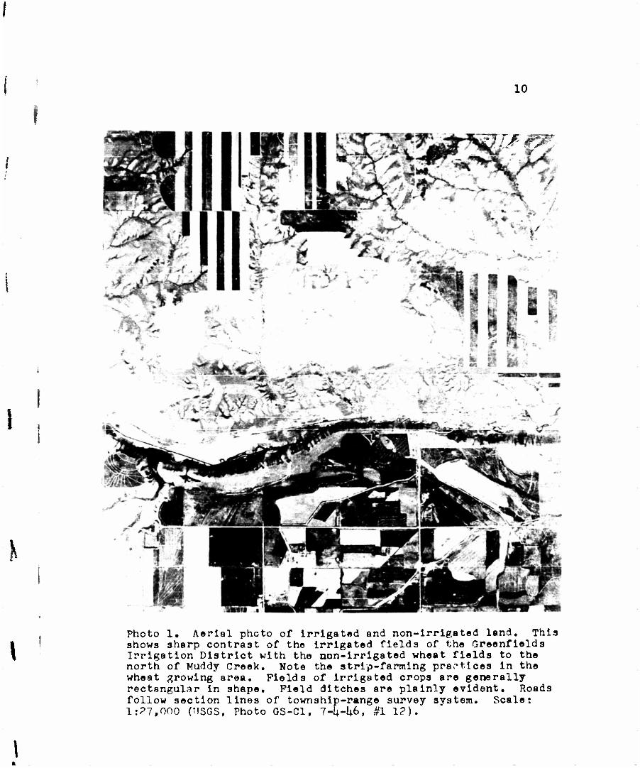
The resulting pattern of settlement is striking indeed
to even the casual traveler. The large holdings of dry-farmed
land give way sharply to small irrigated farms. The change
is sudden and well-marked on the landscape. Aerial photographs
record it just as effectively and strikingly. (See Photo 1).
I !
10
mi- #w.
K
1 Photo 1. Aerial phcto of irrigated and non-Irrigated land. This shows sharp contrast of the irrigated fields of the Greenfields Irrigation District with tho non-irrigated wheat fields to the north of Muddy Creek. Note the strip-farming practices in the wheat growing area. Fields of irrigated crops are generally rectangular in shape. Field ditches are plainly evident. Roads follow section lines of township-range survey system. Scale: 1:?7,000 (TJSGS, Photo GS-C1, 7-U-I+6, #1 1?).

Irrigation Structures Associated with a Gravity-Flow Project
11
\
I !
A gravity-flow project is generally characterized by
three major type3 of structures: storage facilities, a
carriage system, and distribution features.
Water may be supplied for gravity-flow irrigation systems
from wells, natural stream flow, or stored flood water in
reservoirs built for that specific purpose. The natural flow
of rivers is generally insufficient to meet all Irrigation
requirements in a dry or semiarid region throughout the
growing season. It may bo ample until the end of the flood
season; but then the natural rivur flow drops sharply below
Irrigation requirements. As knowledge concerning tne cycle
of water in rivers grew, it becamo apparent that if flood
waters could be captured and stored, not only would existing
areas be assured of sufficient water to mature late-season
crops, but much new land could be added to the irrigated areas,
Most gravity-flow irrigation systems today, therefore, have
Inrge reservoirs or a sorios of reservoirs which serve to
Impound flood waters. Water is released as it is needed to
meot the irrigation requirements during the dry season.
The carriage system consists of diversion dams, supply
canals, tunnels, siphons, and the like. These carry water
from storage facilities to the several areas or divisions
of the irrigated district.

12
Distribution features are the canals and laterals which
deliver water within a specified area or division or an
irrigated district. A distribution system may obtain its
water canalside from a supply canal, or it may obtain the
water from a group of wells or in some instances directly
from the river by pumping or diversion. The exact point
where the carriage system stops and the distribution system
begins varies from project to project, owing to local physical
conditions, terms of repayment contracts, and other factors.
Layout of the Distribution Systems
In order that the photo interpreter may be able to
correlate and interpret irrigation distributaries more
effectively, it is particularly necessary to understand the
general plan of a distribution system.
The main carriage canals subdivide through turnouts into
(1) laterals, (2) sublsterals, and (3) head-ditches, from
which water is finally directed through (ij.) field ditches
over the ground to be irrigated. (Sec Photo 2).
Most canals and ditches ere excavated from the surface
of the countryside through which they run, except where it is
necessary to use earth-fill for banking where one side of
the canal overlooks a depression. In this case, earth and
gravel have been tamped in, then coated with clay and silt
to prevent seepage. Modern canals are often concrete-lined.
This pays dividends in water sa^ed from seepage and in lower
maintenance costs.

r
13
K
i
i
i Photo 2, Aerial view of distribution features. This shows principal distribution features of Greenfields Irrigation District. (A) Greenfields Main Canal (B) Lateral (C) Sub- lateral (D) Head Ditch (E) Border Ditch, and (F) Field Ditches. Scale 1:20,000. (USDA, 1951, Photo ZS-10H-6).
1U
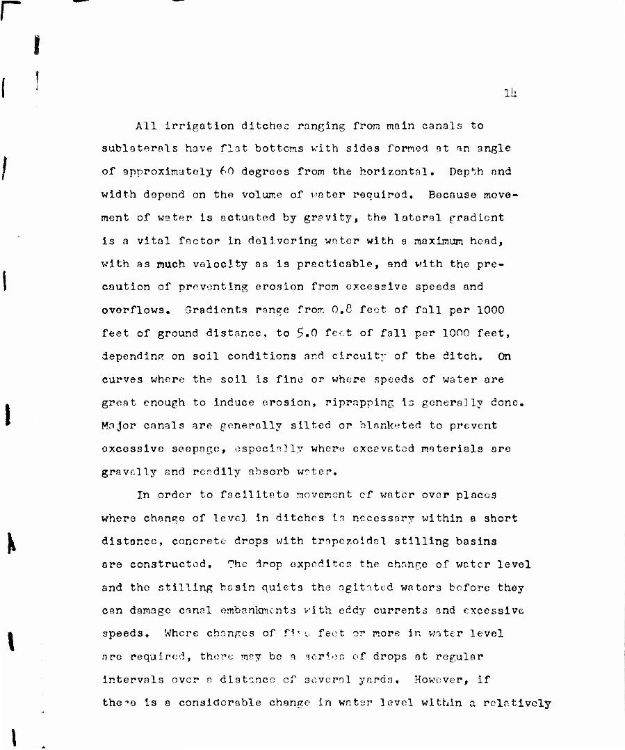
All irrigotion ditchec ranging from main canals to
subloterals have flat bottoms with sides formed at an angle
of approximately 60 degrees from the horizontal. Depth and
width depend on the volume of voter required. Because move-
ment of water is actuated by gravity, the lateral gradient
is a vital factor in delivering water with a maximum head,
with as much velocity as is practicable, and with the pre-
caution of preventing erosion from excessive speeds and
overflows. Gradients mnge from 0.8 feet of fall per 1000
feet of ground distance, to 5.0 feet of fall per 1000 feet,
depending on soil conditions and circuit;- of the ditch. On
curves where the soil is fine or where speeds of water are
great enough to induce erosion, riprapping is genera]ly done.
Major canals are generally silted or blanketed to prevent
oxcessive seepage, especially when; excavated materials are
gravelly and rcrdlly absorb water.
In order to facilitate movement cf water over places
where change of level in ditches is necessary within a short
distance, concrete drops with trnpczoidal stilling basins
are constructed. The drop expedites the change of water level
and the stilling basin quiets the agitated waters before they
can damage canal embankments with eddy currents and excessive
speeds. Where changes of f 1* e feet or more in water level
are required, there may bo a series of drops at regular
intervals over a distance cf sevcml yards. However, if
the-'o is a considerable change in water level within a relatively

I
\
15
short distance so that the rato of fall is groat and of
considerable volume, chutes may bo required. The si7e of the
chute is necessarily smaller than that of the canal, inasmuch
as increased gradient moves water more rapidly, hence requiring
smaller carrying capacity. Like drops, chutes have stilling
basins to quiet disturbed waters. Both tho chutes and stilling
besins are generally constructed of concrete.
From canals, laterals, and subleterals, water is diverted
by means of turnouts which permit the passage of water by
gravity flow into smaller distributary structures. Turnouts
generally consist of a whoel-nnd-shaft valve mechanism and a
division box for controlling the flow of water. Water is
impounded within tho division box by means of cipoletti
checkwiers, the center section of which may be covered by
boards to prevent the flow of water. To one side of tho
trapozoidal outlet in the center of the weir is a metering
guage graduated in tenths of feet. When a flow of water is
desired over the weir outlet, tho center board may be raised
to permit the controlled flow of water.
Head ditchos lead from sublaterals and conduct water to
division boxes or directly to border ditches. Head ditchos
may service two or three farms. Border ditches originate
generally at head ditches or division boxes, follow tho
higher edge of one or more fields, and subdivide into field
ditches. Ditch riders control tho flow of water onto each
farm, whother ir originates at laterals or head ditches;
\
16
farmers are in control of water once it is turned onto their
respective farms.
Farmers control water in border ditches by means of
portable canvas dams or by temporary earthen dams. Being the
smallest major distributary, border ditches are generally
about one foot deep and two feet wide. The use of border
ditches is particularly effective where fields have been
leveled so that the slope of the field is consistent and
regular. Border ditches and head ditches are generally banked
high enough so that the water in them can flow above the general
level of the land, thu3 developing a small amount of head.
Where turnouts are in U30, or where it is expeditious
to do so, various types of dams may be used either in con-
junction with metering weirs and turnouts, or merely to stop
further flow of wnter. There are two principal types of such
dams. In the main canals, radial dams work efficiently and
quickly. However, by far the greatest number of dams are
those constructed of board stoppers which may be removed one
at a time and which are more economical than radial dams.
They are also easy to manipulate in conjunction with smaller
diversion structures.
Drainage Ditches
Because of the generally saturated condition of the soil
in several parts of the District, it has been necessary to
construct drainage ditches to remove surplus waters. These
I
fc
\
17
ditches are triangular in shape as contrasted with the trape-
zoidal shape of major distributaries. They are about ten
feet wide and have been excavated to a dopth of approximately
eight foot. Their location is below and generally parallel
to major canals and laterals and in depressions from which
there are no natural outlets,
Non-Irrigation Structures
There are a number of structures which are not directly
concerned with the distribution of water, but are associated
with an irrigation system. Most important are bridges for
highways crossing canals and laterals having greater than
50-second-feet capacity. Distributaries having capacities
of le ss than 50 second-feet aro generally extended under high-
ways, commonly without change in their water level, in
corrugatod metal pipe culverts. These pipes vary in length
but have a minimum diameter of ?.Q) inches to reduce possibilities
of weed clogging. Where drainage ditches intersect minor
distributaries, water is passed through cross-drainage culverts
across drainage ditches. Likewise, where drainage ditches
with minor flows of water are forced to traverse major water
distributaries, subsurface culverts n-"et the need.
Materials which may bo ordinarily piled beside excavations
are commonly graded so as to form a roadway parallel to the
waterways. This artificial bank stands 5 to 6 feet sbove the
general level of the land. Tho roadway on top of the bank is

!
!
18
used by ditch riders tc attend thoir work of supervising and
operating water distribution facilities during the dry season.
Conclusions
I
\
\
T
Responsibility for the design snd construction of structures
essential to the storage, diversion, conveyance, delivery, and
distribution of water to irrigators rests with the engineer.
It i3 important, therefore, that such structures be built so
that they may be relied on during critical periods. The failure
of a storage dom, as a result of bombing operations or because
of poor design, may cause the loss of large property invest-
ments and sometimes the loss of lives of many people. The
destruction of a diversion dam or the breaking of a canal may
cause the loss of all or part of the structure and very often
the loss of valuable crops by the failure of water when it
is needed.
Irrigated lands nro generally situated great distances
from the source of w^tcr supply. Water obtained from natural
streams and from surface reservoirs, as a rule, must be conveyed
farther than water obtained from underground reservoirs. Carriage
canals m^y vary from a few miles to 100 or more miles in length.
It is necessary, therefore, that a key for the photo
identifieetioxi of irrigation structures belonging to a gravity-
flow irrigation system consist of three parts: (1) a key for the
identification of storage facilities; (2) a key for the identifi-
cation of carriage system structures; and (3) a key for the
identification of distribution features.

r r T
i :
1
x
\
19
Aerial Photo Identification of Structures
Associated with the Greenfields Irrigation District:
Storage Facilities

20
The Gibson Dam
The Gibson Dan is located on the Jlorth Fork of the Sun
River approximately 37 miles west of Fairfield, Montana,
headquarters of the Greenfields Irrigation District. The
surface of the limestone bedrock on which the dam has been
built is very seamy with pronounced stratification. The
structure is a concrete arch 195*5 feet high with a crest
length of 960 feet, a crest width of 15 feet, and a base width
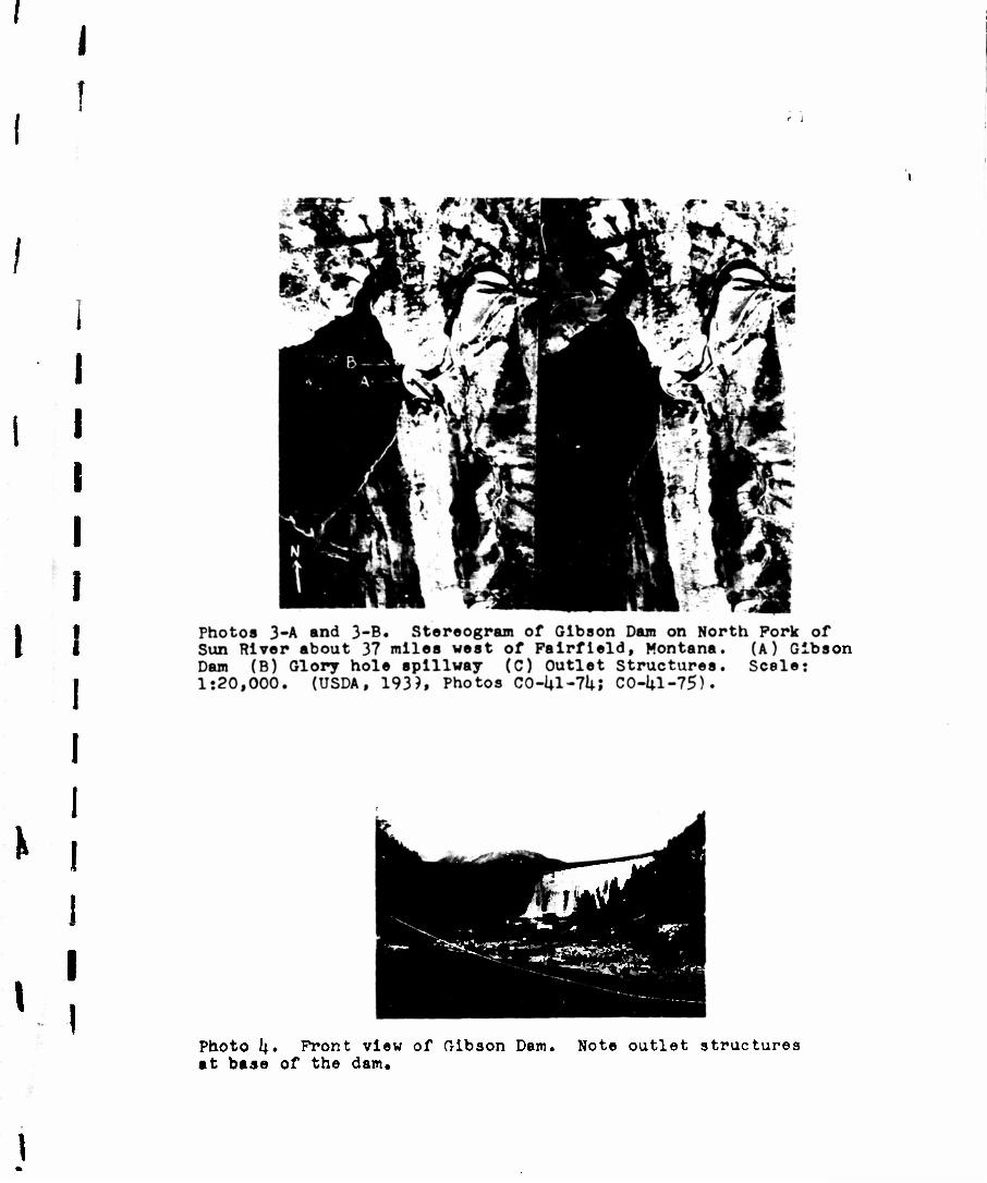
of 87 feet. (See Photos 3-A and 3-B). It has a hydraulic
height of 17U feet. Total volumo of material in the dam is
161,696 cubic yards,
A glory hole spillway is located at the north end of
the dam* (See Photos 3-A and 3-B). It has a capacity of
50,000 cubic feet per second when the water surface is at
elevation U,7?9 feet. The glory ^ole, shaft, and 29.5-foot
diameter tunnol are controlled by six 3U * IP-foot radial gates
at crest elevation 1|,712 feet above mean sea level.
Outlet structures for the dam are two 72-inch diameter
A conduits through the base of the dam, each with a 60-inch
emergencv slide gate and a 60-inch needle valve on tho
downstream end, (See Photo 4). The maximum cepacity of the
outlets is 2000 cubic feet per second.
\
\
i
I !
<• J
I
1 on
\ A
\
I -r- '>?<? VflB*' • Z-~
Photo If.. Front view of Gibson Dam. Note outlet structures at base of the dam.

\
22
Gibson Reservoir
Waters stored by the Gibson Dam occupy a depression
known as Gibson Reservoir with an active irrigation storage
capacity of 105>»000 acre-foot, covering an area of 1,360
acres. It extonds upstream for o distance of seven miles,
and is approximately one mile wide. Construction by the
Utah Construction Company was completed according to contract
specifications in July, 1929, and storage of water begun
Immediately. In 193^> effective use of the waters of
Gibson Reservoir was being made.
\

r v
?3
I
\
\
I
Photo 5. Aerial photo of Gibson Reservoir. Waters are Impounded by Gibson Dam for a distance of 7 miles upstream. Gsale 1:?0,000 (USDA, 1939, Photo CO-I4.I-76)
2U
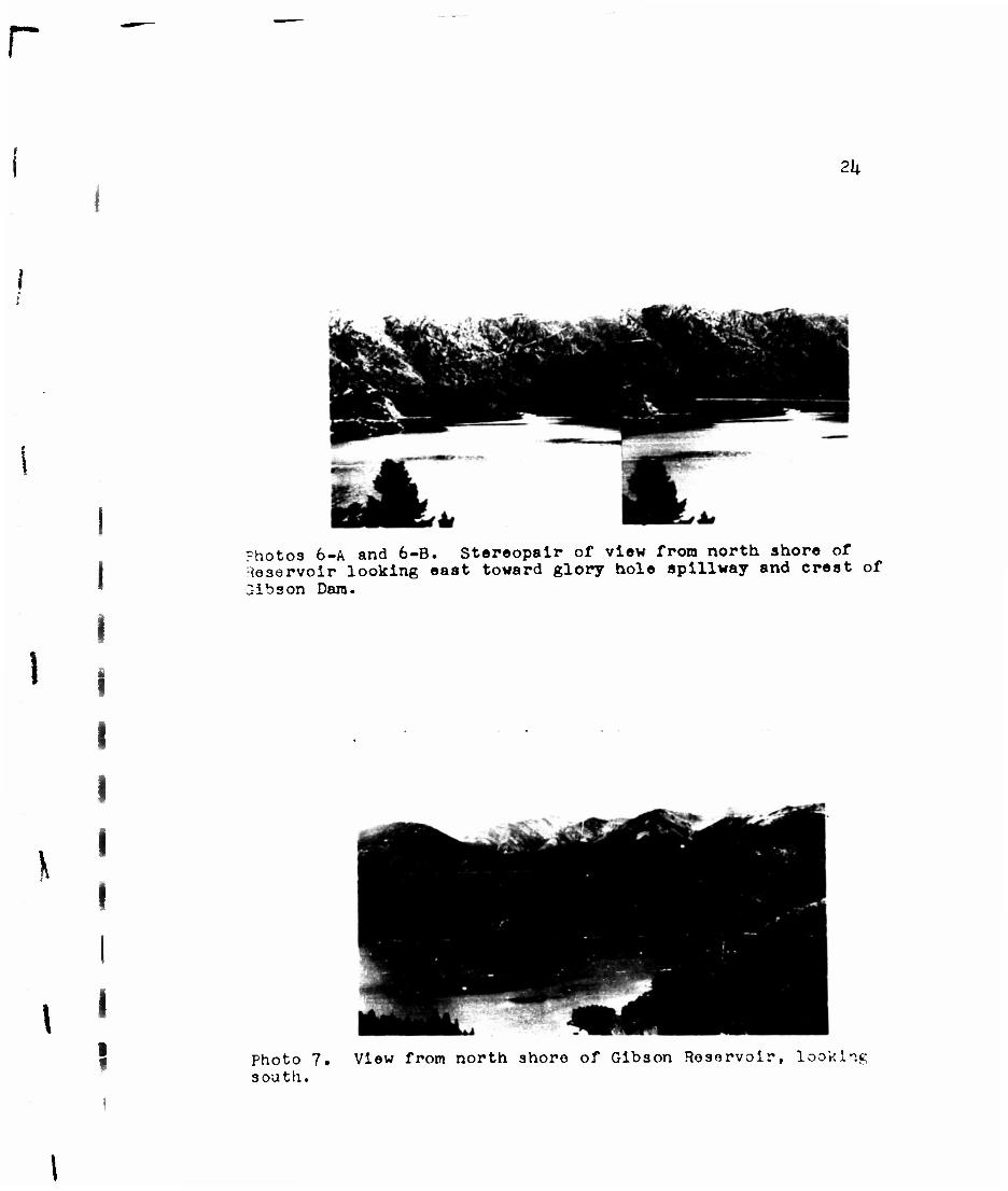
Photos 6-A and 6-B. Stereopalr of view from north shore of Reservoir looking east toward glory hole spillway and crest of 3ibson Dam.
\
\ I
8 Photo 7. View from north shore of Gibson Reservoir, looking south.
I
\
25
Aerial Photo Identification of Structures
Associated with the Greenfields Irrigation District
Carriage System

r
26
Diversion Dam
I Diversion Dam was completed in 1909 a3 the first
structure for the diversion of Sun River waters. Prior
to the construction of Gibson Dam, Diversion Dam furnished
the only facility for clalitifng waters of Sun River for
purposes of irrigation. Gibson Dam has replaced its function
I as a regulator, insuring adequate water supply at all times.
Now Diversion Dam is a secondary structure in the storage
system, although it still retains its function of diverting
waters from Sun River.
Diversion Dam is located downstream 3 miles from
Gibson Dam. It is a concrete arch-gravity structure. (See
l Photos 8-A and 8-B). It has a structural height of 131 feet;
crest length of 21+3 feet; crest width of 7«5 feet; and a base
width of I4.O feet. The outlet is 11 foet in diameter and has
a maximum capacity of D4.OO cubic feet per second at a surface
elevation of 1+»U71»1 feet abovo sea level.
. Water is diverted directly at Diversion Dam into Willow
• Creek Feeder Conol to Willow Creek Reservoir; thonce to
Port Shaw Irrigation District. Water i3 also diverted at
the same point to the Pishkun Supply Canal and Pishkun
Reservoir; thence to Greenfields Irrigation District.
t
\
21
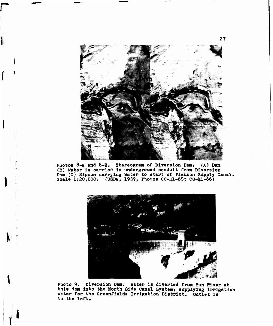
: Photos 8-A and 8-B. Stereogram of Diversion Dam. (A) Dam (B) Water is carried in underground conduit from Diversion Dam (C) Siphon carrying water to start of Pishkun Supply Canal. Scale 1:20,000. (USDA, 1939, Pliotos CO-1^1-65; CO-la-oo)
t A
• . -• *
W
\
\
• •' II li t ~* J "1*.
z&z
»»
Photo 9* Diversion Dam. Water is diverted from Sun River at this dam into the North Side Canal System, supplying irrigation water for the Greenfields Irrigation District. Outlet is to the left.

I
\
28
Siphon of Pishkun Supply Canal
Water token from Diversion Dare flows through a
650-foot tunnel through the csnyon wall on the south side
of Sun River; thence through e conduit 370 feet in length.
At the end of the conduit, the water is taken northward
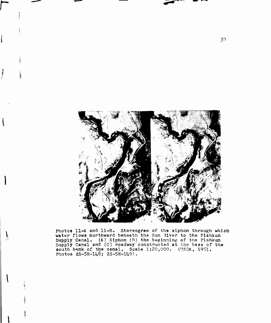
beneath the Sun River through a siphon, 70C feet in length,
to the start of the Pishkun Supply Canal. (See Photos 11-A
and 11-B).

!
\
i
!
Photo 10. Siphon through whioh water la carried from south aide of Sun River to north. Note that the location of the siphon on the far slope is indioated by the broken surface whore the trench containing the siphon has been filled. The embankment at the far end of the siphon marks the start of tho Pishkun Supply Canal. Road which crosses river on bridge continues along base of south bank of Pishkun Supply Canal to Pishkun Reservoir.
30
\
Photos 11-A and 11-3. Stereogram of the siphon through which water flows northward beneath the Sun 3iver to the Pishkun Supply Canal. (A) Siphon (B) the beginning of the Pishkun Supply Canal and (C) roadway constructed at tho base of the south bank of the canal. Scale 1:20,000. (USDA, 1951, Photos ZS-5H-1U8; ZS-5H-1U9).

1
\
\
31 !
Pishkun Supply Canal
The Pishkun Supply Canal ia built through the rough
foothill country eastward from the eastern front of the
I.ewis Range, between the Diversion Dam and th>. Pishkun
Reservoir, a distnnco of 12 miles. The surface materials
of r-ock and coarse Travel cause excessive seepage of water
and have been the soiree of much troublet The canal has
a capacity of 12.00 cubic f. -,t per second*

3?
Photos 12-A and 12-B. Stereograra of Pishkun Supply Canal between' Diversion Dam and Pishkun Reservoir. On stereogram note (A) bridge over canal and (B) blanketing of canal on outside of bend to prevent erosion and seepage. Scale 1:20,000. (USDA, 1951, ZS-5H-5, ZS-SH-U)
\
Photos 13-A and 13-P. Stereopair of Pishkun Supplv Canal looking westward toward Lewis Range from eastern terminus of Canal. Noto embankment on south side of canal.
«
33
Pishkun Reservoir
The Pishkun Reservoir occupies a basin which, is enclosed
by an inner moraine of the former Sun River '"lacier. (See
Photo lij. ) . The reservoir site embraces a series of connected
lake beds almost on the divide between the Sun and Teton
River drainage systems, appro::imately l!_j_ miles east of
Diversion Dam.
Pishkun Reservoir has an active storage capacity of
32,050 acre-feet. It is formed by a series of eight earth-fill
dikes, with a crest width of 20 feet, an average maximum
height of 23.5 feet, and an overall length of 9,050 feet.
(See Photos \$ and 16-A ? B). The outlet is a 12-foot
diameter concrete conduit with a maximum capacity of 1600
cubic feet per second.
I

•r *£**
&•:
- t-'* flP*f * f4 »* ' sack
V. ?«
o •p o O 4J £ o
P-,
en S3 — 'Si
i

35
1
\.
Photo 15>» Small dam along north aide of reservoir. (See Photo Ik)
photos 16-A and 16-B. Stereopair of earth-filled dam at the northeastern end of Pishkun Reservoir. Note road on top of dam. Picture taken looking southeastward from northwest end of dam. (See Photo lU)
I
36
1
\.
Sun River Slope Canal
Prom Pishkun Reservoir the irrigation waters flow
southeastward for 25»9 miles through the Sun River Slope
Canal to the head of Big Coulee into which some water is
released. Beyond Big Coulee the carriage system is known
as the Spring Valley Canal, which extends eastward llj.»2
miles to Fairfield.
The maintenance of the Sun River Slope Canal has been
complicated by the rolling character of the area. It has
been necessary to cement the sides and bottom of the canal
for the first ten miles southeast of Pishkun Reservoir.
The Sun Rivor Slope Canal has a capacity in excess
of 1200 cubic feet per second. The first major turnout
into a lateral is eight miles southeast of the Pishkun
Reservoir.

r 37
I Photos 17-A and 17-B. Stereogram of Sun River Slope Canal. Material excavated from the canal appears as a wide, light- colored ribbon along the bank of the canal* Northern bank is light in tone due to the lack of vegetation. Base width of canal is about 60 feet, water depth about 7f feet. Road width about 20 feet. Side slopes of canal: 2 to 1. (A) Point at which Photo 18 was taken. Scale 1:20,000 (USDA, 1951, Photo ZS-BH-25-26)
V
\
Photos 18-A and 15-B. Stereopair of Sun River Slope Canal looking eastward from point indicated on stereogram above.
\
\
36
Aerial Photo Identification of Structures
Associated with the Greenfields Irrigation District:
Distribution Features

\
39
General Characteristics of
Distribution Features Greenfields Irrigation District
The distribution features of a gravity-flow irrigation
system generally consist of a main canal with its laterals,
sublaterals, and head ditches. From the head ditches water
is directed through border ditches from which it is spread
over the ground by means of field ditches.
In general, laterals in the Greenfields Irrigation
District hav6 been designed to serve from 3,000 to 3»500
acres. A lateral with its sublaterals has an average total
length of 12 to \$ miles.
For the most part the canals and ditches of the distribu-
tary system of the Greenfields Irrigation District have been
I excavated from the surface of the countryside across which
they traverse. Only where one side of the canal overlooks
a depression has it been necessary to use earth-fill for
banking. In such a case, earth and gravel have been tamped
in, then coated with clay and silt to prevent seepage,
\ All irrigation ditches ranging from main canals to sub-
laterals have flat bottoms with sides formed ut an angle of
approximately 6C° from the horizontal. The depth and width
depend upon the volume of water to be carried.
Because the movement of water is actuated by gravity,
the lateral gradient is n vital factor In delivering water
with a maximum head, with as much velocity as is practicable,
\
r
i
i
i
t !
but with the precaution of preventing erosion from oxcessivo
speeds and overflows. Gradients ronpe from 0.8 feet of foil
per 1,000 feet of distance to 5.0 feet of fall per 1,000 feet,
depending upon coll conditions and on the circuity of the
ditch. On curves where fine materials constitute mantle
rock, and where speeds of the water are great enough to
induce erosion, ripr&pping is commonly done.

^;.-
ii P;:Oto 19. Generp.l aerlnl view of a portion of the Greenfields Irrigation District, showing the distribution features. Scale 1:20,000. (USDA, 1901, Photo ZS-1QH-6).
(A) Greenfields Main Canal (F.'.) Lateral (C) Sublateral (D) Head ditch I"•-'.) Border ditch (?) ''ield ditches ((i) Turnout ("• "i.ock r-ar.'•
(1) Division Box-:;. (J) Drop* (K) Chutes (I.) Stilling Basin (M) Sluice (N) Conduit (0) Drainage n*tch
i s t. •:t1 jrer, nc t shown on above photoftranh
i
\
\
\
k-2
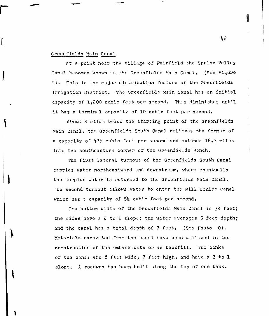
Greenfields Main Canal
At a point near tbfi village cf Foirfleld the Spring Valley-
Canal becomes known 33 the Greenfields Main Canal. (See Figure
2). This is the major distribution feature of the Greenfields
Irrigation District. The Greenfields Main Canal has an initial
capacity of 1,200 cubic feot per second. This diminishes until
it has a terminal capacity of 10 cubic feet per second.
About 2 miles below the starting point of the Greenfields
Main Canal, the Greenfields South Canal relieves the former of
a capacity of l\2S cubic feet per second and extends 16.7 miles
Into the southeastern corner of the Greenfields Bench.
The first lateral turnout of the Greenfields South Canal
carries water northeastward and downstream, where eventually
the surplus water is returned to the Greenfields Main Canal.
Tho second turnout allows water to enter the Mill Coulee Canal
which has a capacity of 5U cubic feet per second.
The bottom width of the Greenfiolds Main Canal is 32 foet;
the sides have a 2 to 1 slope; the water averages 5 feet depth;
and the canal has a total depth of 7 feet. (Sec Photo 0).
Matorials excavated from the canal r.avc been utilized in the
construction of the embankments or as backfill. The banks
of the canal arc 8 feet wide, 7 feet high, and have a 2 to 1
slope. A roadway has been built along the top of one bank.

1*3
Photos 20-A and 20-B. Stereogram of the Greenfields Main Canal. Note the roadway along the canal embankment. The embankment was constructed with material excavated from the canal. On the stereogram the vegetation appears as a dark margin along both sides of the road. (A) Indicates point at which Photo 21 was taken. Scale 1:20,000. (USDA, 1951, Photos ZS-10H-5, ZS-10H-6)
k
I photos 21-A and 21-B. Stereopair of Greenfields Main Canal, looking southwest from a bridge on Third Lane Road, at the edge of the southwest portion of Section 31, T 2?N, R 2W. Road Is on tho right bank of the canal, (See Photo 20).

I
\
\
Uk
Head Ditches
Head ditches lead from sublaterals. Head ditche.3 may
serve two or three farms, where they conduct water directly
to border ditches or to division boxes. (See Photo 22). Head
ditches are the smallest units of the distributary system,
through which the flow of water is controlled by ditch riders.
Border Ditches
Border ditches originate generally at head ditches or
division boxes end follow the higher edges of one or more
fields. The border ditches are genoi'ally about one foot deep
and two feet wide. The use of border ditches is particularly
effective where the fields have been leveled so that the
slope of the field i3 consistent and regular. Border ditches
and head ditches are generally banked high enough so that
the water can flow above the general level of the land, thus
permitting a small amount of head. Farmers assume control
of the flow of the irrigation water after it has been diverted
into the border- ditches.
Field Ditches
The border ditches are subdivided into field ditches.
(See Photo 23). These conduct the water directly to the
crops to be irrigated.

us
1 t I
Photo 22. A head ditch along a highway. Note the turnoff into the border ditch. Por aerial view of above ditch see (D) on Photo 19.
I
\
I
{
Photo 23o Pield ditches leading from a border ditch. Hay has been cut and the field is being used as a pasture for dairy cows. These ditches appear on aerial photographs as roughly parallel ?czt'^re; »Ttendin* northeastward from the border ditch toward the drainage ditch. (P) on Photo 19•
Por aerial view of above field ditch sea

I
fc
46
Turnouts
From the main canal, laterals, sublaterals, and smaller
ditches, the water is diverted by means of turnouts. These
permit the passage of water by gravity flow into successively
smaller distributarv units. Turnouts generally consist of a
wheel-and-shaft valve mechanism for permitting a flow of
water as desired.
Check Dams
Where turnouts are in use, or where it is expeditious
to do so, various types of dams may be used. In the main
canals the radial dams work efficiently and quickly. However,
by far the greatest number of dams consist of board stoppers
which may be removed one at a time and which are more economi-
cal to construct thr.n rndial dam3. They are also easier to
manipulate in conjunction with smaller diversion structures.
t I
\
r
U7
/
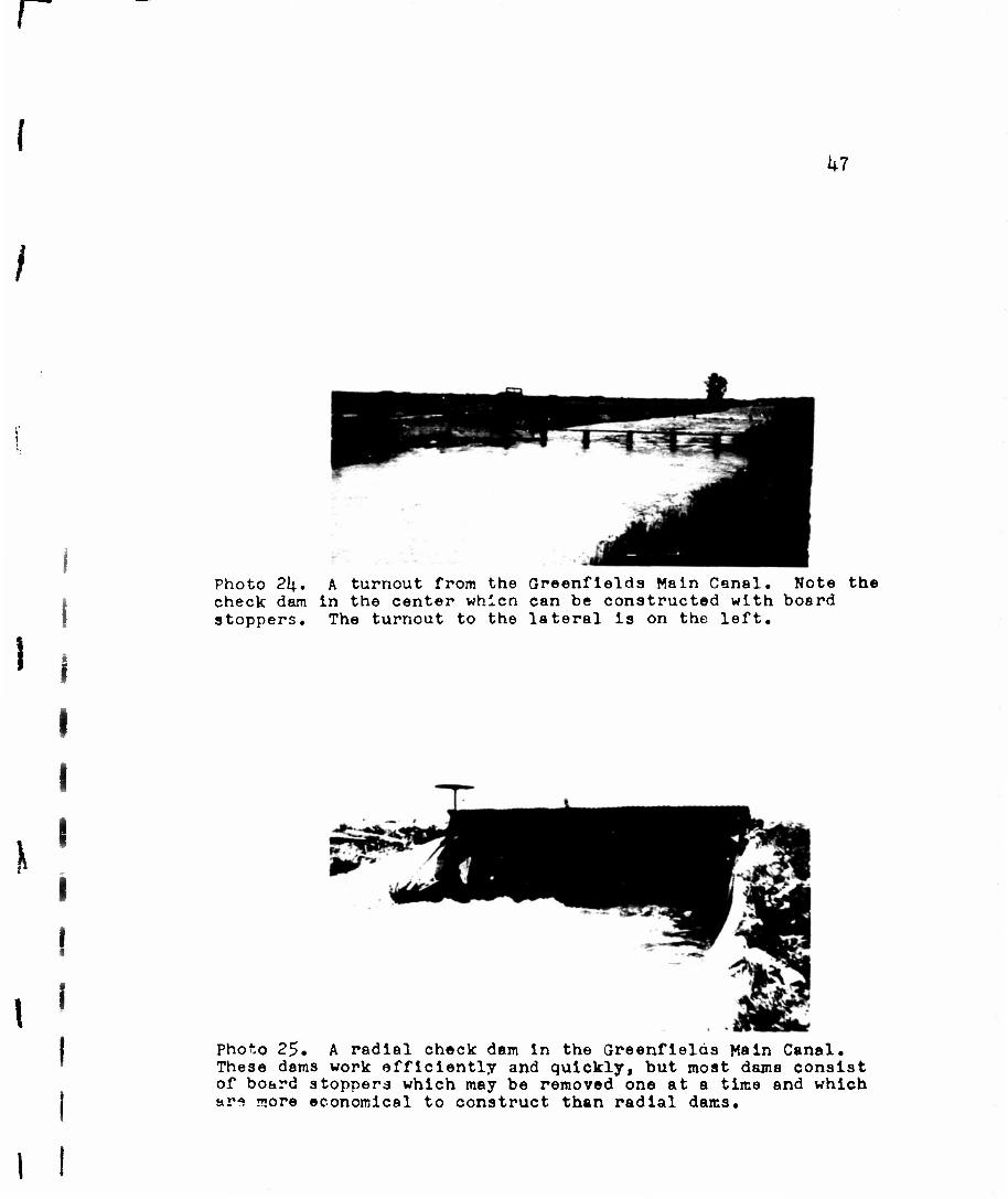
Photo 2l|. A turnout from the Greenfields Main Canal. Note the check dam In the center whicn can be constructed with board stoppers. The turnout to the lateral is on the left.
\
Photo 25. A radial check dam in the Greenfields Main Canal. These dams work efficiently and quickly, but most dams consist of board stoppers which may be removed one at a time and which ar* more economical to construct than radial dams.
I I

Special Structures
Water flows from head ditches into cement divisi on boxes
| from which it is then turned out into border ditches. The
water is contained within the division box by means of a
cipoletti checkweir, the center section of which may be
covered by boards to prevent the flow of water.
On one side of the trapezoidal outlet in the center of
t the weir is a metering gauge which is graduated in tenths of
feet. When a flow of water is desired over the weir outlet,
the center board may be raised to permit the controlled flow
of water.
I
\
\

r
k9
1
Fhoto 26. Ground appearance of a turnout from a head ditch northward into a border ditch. Note the wheel-and-shaft mechanism for controlling the flow of water. The water flows from the turnout into a division box, where the water is impounded by means of a checkwelr. Note the trapezoidal shape of the checkweir. The center section of the weir may be covered by boards to prevent the flow of water northward and to direct it east or west as de- sired. For aerial view of above feature see (G) on Photo 19.
y
< i Fhoto 27, A closeup of a cipoletti checkweir. Note the metering gauge on the right side of- the outlet in the center of the weir. Not possible to detect on aerial photographs.

r
&
50
Miscellaneous Fogtures
In order to expedite tho movement of water where '•.
change of level in ditches is necessary within o short
distance, concrete drops with trapezoidal stilling basins
aro ofton constructed. The drop accomplishes the chango
in water level and the stilling basin quiets the agitated
water before it damages the canal embankments with eddies
and excessive speeds.
Where changes in water ljvel of five feet or more are
required, there may be a series of drops at regular intervals
within a distance of several Yards. However, if there is
a considerable change in water level within a relatively
short distance, so that the rate of fall is gnat and of
considerable volume, concrete chutes may be required. The
width of the chutu is necessarily smaller than that of the
canal sLnce the increased gradient moves the water more
quickly. Like drops, chutes have stilling basins to quiet
the disturbed water.
Often sluices and conduits are necessary to carry
laterals, sublatt-rais, and head ditches -.cross roads or
over drainage ditches. These may be constructed of wood
or galvanized Iron.
\

r 51
Photo 28. A single drop. These are located whore there Is a change of level of less than 5 feet. On aerial photos a drop appears only as a dark Indistinct feature In the canal. Often drops are located where a change in level is associated with a change in direction. The stilling basin below the drop appears on aerial photos as a widening in the canal.
\
\ Photo 29, A series of drops, base of each drop.
Note the stilling basins at the

••?.
\ ! t
i
Photos 30-A and 30-B. Stereograra of a chute. Constriction in of canal is apparent. Abrupt change in direction of flow
end of chute is characteristic. The check at upper end is scarcely discernible. (A) Funnel-shaped upper end indicates direction of flow. (B) Stilling basin at of chute is identified by agitated water which appears
on the lower side of check. (C) Gradual curve of the canal leaving stilling basin indicates the lower end of
(USDA, 1951, Photo ZS-10H-5, ZS-10H-6).
width at upper of chute of chute lower end foamy white the ci --u - — cnute. Scale 1:20,000.
\ I
\

r
\ ,
rn-;tD3 31-A end 31-B. Stereopair of chute Indicated in Photo 30, ~~-.re ci?, looking down slope of chute. Observe Inclined concrete -Lies ar.ri in the ri^ht foreground may be seen 8 portion of the wlJ(!r, funnel-shaped upper end of chute. Check and stilling bnsin may be observed a I foot of chute, where Greenfields Main "•>::<•'. turns toward eost-northeast. A main lateral turns toward
sni carries wnter beneath the road. Also shown as T ) •/
w e:u on Photo 19.
5k
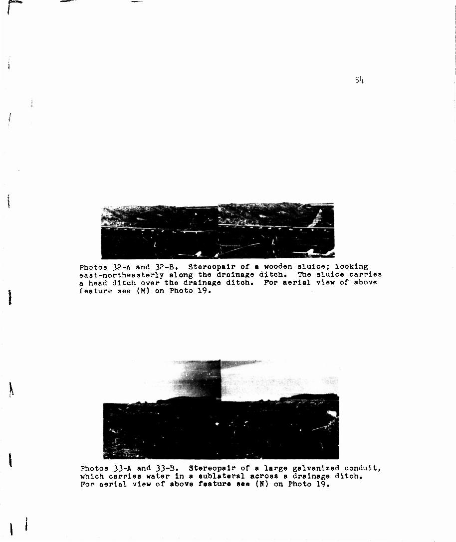
Photos 3?-A and 32-B. Stereopair of • wooden sluice; looking ea9t-northeasterly along the drainage ditch. The sluice carries a head ditch over the drainage ditch. For aerial view of above feature see (M) on Photo 19.
\
Photos 33-A and 33-3. Stereopair of a large galvanized conduit, which carries water in a sublateral across a drainage ditch. For aerial view of above feature see (N) on Photo 19.
I «

55
Drainage Ditches
Because of the generally saturated condition of the
soil in several parts of the Greenfields Irrigation District,
it has been necessary to construct drainage.; ditches to remove
the surplus water that has accumulated as a result of
irrigation and seepage losses. These ditches are commonly
triangular in shape as contrasted with the trapezoidal shape
of major distributaries. They are about ten feet wide and
have been excavated to a depth of about eight feet. Their
location is below and generally parallel to major canals
and laterals or in depressions from which there are no
natural outlets. There is no unit of the Greenfields Irriga-
tion District which is entirely free from drainage problems,
but the problem is more acute where surface configuration
and Impervious soils result in a high water table.
In some cases, water from drainage ditches on the
upper benches flows Into sublaterals at lower levels if
adequate quantities of usable water have been collected.
Otherwise, drainage ditches empty into wasteways.

Photos 3ll-A and 3U-P. Steroogram of drainage ditch. Its tone is much darker than a canal, due to Its greater depth. Trains 9re constructed on straight lines wherever practical. Scale l;?0t000. (T';SDA, 1951, Photos ZS-10H-5, ZS-10H-6).
\
Photos 35-A and 35-B. Stereopalr of drainage ditch, looking southwesterly along the ditch from a road. Note that there Is no road along either embankment of the drainage ditch. Also nottr the vegetation In the stagnant water. For aerial vlow of above feature see (0) in Photo 19.