ad-a278 230 o p form approved udh iujflh e .1 o · dr s s apr1 9 1994 ..; 7. performing...
TRANSCRIPT
.. O P Form Approved
AD-A278 230 MTION PAGE N o 0704-0188 01)Udh IUjflH e 22C2- .,. .1 o1. AGENCY USE ONLY (Leave blanik) 2.REPORT DATE 3. REPORT TYPE AND DATE$ COVERED~
115 April 1994 Final_____________4. TITLE AND SUBTITLE 5. FUNDING NUMBERS
Test Operations Procedure (TOP)1-2-612 Nuclear Environment Survivability WU A268445
ELECTE :
DR S S APR1 9 1994 ..;7. PERFORMING ORGANIZATION NAME(S) AND ADDRESS(E W, PERFORMING ORGANIZATION
Commander REPORT NUMBER
U. S. Army Whi:e Sands Missile Range Test OperationsATTN: STEWS-NE-A Procedure (TOP)White Sands Missile Range, NM 88002 1-2-612
9. SPONSORING, MONITORING AGENCY NAME(S) AND ADDRESS(ES) 10. SPONSORING MONITORiNGCommander AGENCY REPORT NUMBER
U. S. Army Test and Evaluation Command Same as item 8ATTN: AMSTE-CT-TAberdeen Proving Ground, MD 21105-5055
1l. SUPPLEMENTARY NOTES
12a. DISTRIBUTION AVAILABILITY ST
ATEMENT 12b. DISTRIBUTION COL,:
Approved for public release:Distribution unlimited
13. ABSTRACT (Maximum 2Q0 words)
This TOP provides a general outline of the test and analysis procedures requiredto determine the effects of specified nuclear environment on Army materiel. Thepurpose of these test and analysis procedures is to ascertain the degree to whichthe Operational Requirements Document (ORD), Independent Evaluation Plan (IEP)/Independent Assessment Plan (lAP) criteria, and Army Nuclear Hardening Criteria(NHC) are met.
00
94-11678
S14. SUBJECT TERMS 15. NUMBER OF PAGES
SNuclear thermal radiation Neutron fluence 116Gamma dose rate 16. PRICE CODO
Nuclear environments17. SECURITY CLASSIFICATION 186 SECURITY CLASSIFICATION 19. SECURITY CLASSIFICATION 20. LIMITATION OF ABSTRACT
OF REPORT OF THIS PAGE OF ABSTRACT
LJCLASSIFIED SARNSN 7540-01-280-5500 (i " ,, -\ 7 Sianoaa>. ;*rr 298 (Rev 2-89)
P-CV' .J -k) ) 4^ ,(_ 3q-
/"
DEPARTMENT OF THE ARMYHEADOUARTERS, U.S. ARMY TEST AND EVALUATION COMMAND
ABERDEEN PROVING GROUND, MARYLAND 21005-5055 5REPLY TOATTENII•ON OF--
AMSTE-CT-T '70-10p) APR 1994
MEMORANDUM FOR Administrator, Defense Technical InformationCenter, ATTN: DDAC, Cameron Station,Alexandria, VA 22304-6145
SUBJECT: Test Operations Procedure (TOP) 1-2-612, NuclearEnvironment Survivability, 15 Apr 94
1. Enclosed are DTIC Form 50 (Encl 1) and two copies of subjecttest operations procedure (Encl 2) for assignment of accessionnumber.
2. This TOP supersedes TOP 1-2-612, AD No: A069845, 12 Apr 79,which should be removed from your library and discarded.
3. Point of contact at this headquarters is Mr. Wolfgang HR.Schmidt, AMSTE-CT-T, [email protected], DSN 298-1486.
FOR THE COMMANDER:
2 Encls RICHARD A. HA ESActing Chief, Tech Dev DivDirectorate for Corporate Information
and Technology
//•'" • // .

US ARMY TEST AND EVALUATION COMMANDTEST OPERATION PROCEDURES
*Test Operations Procedure (TOP) 1-2-612 15 April 1994AD No.
NUCLEAR ENVIRONMENT SURVIVABILITYPage
PARAGRAPH 1. SCOPE. ........................... 22. FACILITIES AND INSTRUMENTATION (F&I) ........ ........... 22.1 Nuclear Airblast F&I ............... ................... 22.2 Nuclear Thermal Radiation F&I .......... ............... 42.3 HEMP/SREMP F&I ................... ...................... 62.4 Gamma Dose Rate F&I ................ .................... 82.5 Neutron Fluence F&I ................ .................... 102.6 Total Gamma Dose F&I ........... ................... ... 123. REQUIRED TEST CONDITIONS ......... ................. ... 143.1 Test Preparation ............. ..................... ... 143.2 Test Execution .......................... 183.3 Test Reporting and Life-Cyc].e ...... ............... ... 193.4 Nuclear Airblast Pretest Analysis ... ............. 213.5 Nuclear Thermal Radiation Pretest Analysis ... ........ .. 223.6 HEMP/SREMP Pretest Analysis ........ ................ ... 233.7 Gamma Dose Rate Pretest Analysis ......... ............. 243.8 Neutron Fluence Pretest Analysis ..... ............. ... 253.9 Total Gamma Dose Pretest Analysis ..... ............. ... 264. TEST PROCEDURES .............. ...................... ... 274.1 Nuclear Airblast ............. ..................... ... 274.2 Nuclear Thermal Radiation ........ ................. ... 294.3 HEMP/SREMP ................. ........................ ... 304.4 Gamma Dose Raze .............. ...................... ... 334.5 Neutron Fluence ..... ............ ... ......... ... 374.6 Total Gamma Dose ............. ..................... ... 405. DATA REQUIRED .............. ....................... ... 445.1 Nuclear Airblast ............. ..................... ... 445.2 Nuclear Thermal Radiation ........ ................. ... 455.3 HEMP/SREMP ................... ............ . ........... 465.4 Gamma Dose Rate .............. ...................... ... 485.5 Neutron Fluence .............. ...................... ... 495.6 Total Gamma Dose ............. ..................... ... 506. PRESENTATION OF DATA ........... ................... ... 526.1 Data Appropriation and Compliance ..... ............. ... 526.2 Data Reduction ............... ...................... .. 526.3 Data Presentation ............ ..................... ... 54
APPENDIXES A. GENERAL NUCLEAR WEAPON EFFECTS .... .............. A-1B. NUCLEAR AIRBLAST ENVIRONMENT AND EFFECTS (E&E) ......... .. B-1C. NUCLEAR THERMAL RADIATION E&E ........ ............... .C-1D. ELECTROMAGNETIC E&E ............ .................... .. D-1E. NUCLEAR RADIATION E&E .......... ................... .. E-1F. DETAILED TEST PLAN SUBTEST EXAMPLE ..... ............ ..F-I
"*This TOP supersedes TOP 1-2-612, 12 April 1979.
Approved for public release; distribution unlimited.
I
TOP 1-2-61215 April 1994
G. DATA TABLES AND DOCUMENTATION ......... ............ .. G-lH. ABBREVIATIONS .............. ....................... ... H-II. GLOSSARY .................... ......................... I-1J. REFERENCES ..................... ........................ J-1
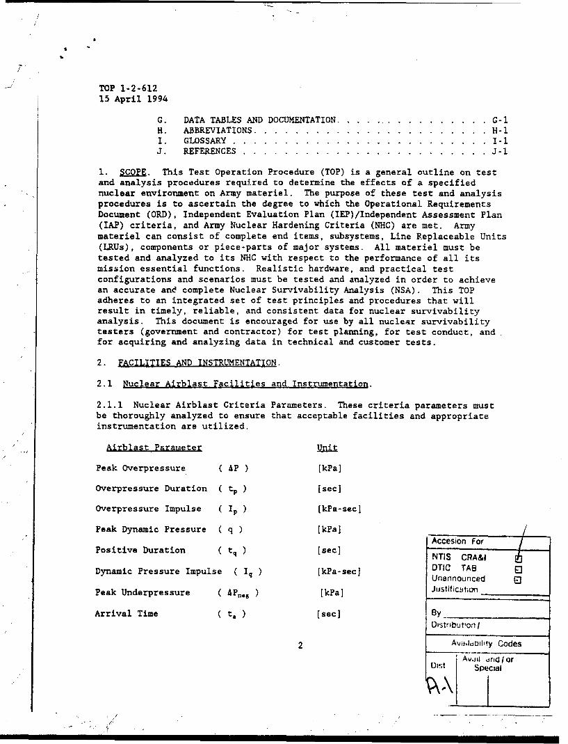
1. SCOPE. This Test Operation Procedure (TOP) is a general outline on testand analysis procedures required to determine the effects of a specifiednuclear environment on Army materiel. The purpose of these test and analysisprocedures is to ascertain the degree to which the Operational RequirementsDocument (ORD), Independent Evaluation Plan (IEP)/Independent Assessment Plan(IAP) criteria, and Army Nuclear Hardening Criteria (NHC) are met. Armymateriel can consist of complete end items, subsystems, Line Replaceable Units(LRUs), components or piece-parts of major systems. All materiel must betested and analyzed to its NHC with respect to the performance of all itsmission essential functions. Realistic hardware, and practical testconfigurations and scenarios must be tested and analyzed in order to achievean accurate and complete Nuclear Survivability Analysis (NSA). This TOPadheres to an integrated set of test principles and procedures that willresult in timely, reliable, and consistent data for nuclear survivabilityanalysis. This document is encouraged for use by all nuclear survivabilitytesters (government and contractor) for test planning, for test conduct, andfor acquiring and analyzing data in technical and customer tests.
2. FACILITIES AND INSTRUMENTATION.
2.1 Nuclear Airblast Facilities and Instrumentation.
2.1.1 Nuclear Airblast Criteria Parameters. These criteria parameters mustbe thoroughly analyzed to ensure that acceptable facilities and appropriateinstrumentation are utilized.
Airblast Parameter m~it
Peak Overpressure ( AP ) [kPa]
Overpressure Duration ( tp ) [sec]
Overpressure Impulse ( Ip ) [kPa-sec]
Peak Dynamic Pressure ( q ) [kPa] /SAccesion For
Positive Duration ( tq ) [sec] NTIS CRA&IDynamic Pressure Impulse ( Iq ) [kPa-sec] DTIC TAB
Unannounced
Peak Underpressure ( APnes ) [kPa] Justitfictin
Arrival Time ( t, ) [sec] 8 yDistributionri
AvdiidDibIty Codes
Avjid iridjIorOist ASpecial
N

TOP 1-2-61215 April 1994
Performance criteria requirements of the test system include allowabledowntime and recovery procedures, operate through, acceptable damage anddegradation, and the availability of and time required to implement repair andreplacement parts.
2.1.2 Nuclear Airblast Facilities.
Acceptable test facilities ,an be categorized as either large-scaleHigh-Explosive (HE) field tests, or threat relatable shock tubes. Majormilitary systems should utilize a large-scale HE field test because of thesystem's size, mass, and response; while existing shock tubes should beutilized for small systems or subsystems that are attached to a rigidstructure. In general, items that can translate or be damaged by ground shockshould be tested at an HE event. Examples of acceptable facilities are:
Facility y Location Comments
1. DNA PHETS HE Field Test WSMR, NM Large test areaBi-AnnualUp To 16 kT simulationsDistributed system level
2. USA ARL Shock Tube APG, MD Tube Width - 2.4 m2.4 m Max Overpressure - 138 kPa
Max Duration - 750 msComponent, LRU, andSmall System level
3. USA WSMR Shock Tube/ WSMR, NM Construction Completed FY94LBTS Thermochemical On Completion, Preferred
Reaction US FacilityTube Width - 20.0 mMax Overpressure - 241 kPaMax Duration - 3300 ms0.1 kT - 3MT System level
Other airblast facilities available for nuclear airblast testing arelisted in Defense Nuclear Agency (DNA) publication, DASIAC SR-90-252, "Guideto Nuclear Weapons Effects Simulation Facilities and Techniques1 " (1990Edition) on pages 2-4 through 2-48. The Project Engineer (PE) must ensurethat the airblast test facility utilized is the foremost facility availablefor the desired criteria, test system configuration, and the anticipatedresponses. It is important that a pretest analysis be performed so that thebest test facility will be selected to provide the best available stimulus forproducing the primary responses in the test system. It is emphasized thatavailable facilities will provide only a simulated nuclear blast environment.
"Superscript numbers/letters correspond to those in Appendix J, References.
.3

TOP 1-2-61215 April 199.,
Therefore, in addition to test data adequate analysis must be performed toaccount for the facility deficiencies which must be known, quantified, anddocumented.
2.1.3 Nuclear Airblast Instrumentation.
Devices for Measuring Preferred Device Desired Measurement Accuracy
1. Pressure Pressure-Transducers ± 10 Z
2. Strain Strain Gages ± 10 Z
3. Acceleration Accelerometers ± 10 z
4. Translation High Speed Camera 250 400 fps
These measuring devices should be positioned at locations on the testitem based upon the pretest response analysis. Data transmissions arenormally through twisted pair cable. Transmitted data are normally input toadjustable gain instrumentation amplifiers and transient data recorders withan operating bandwidth of 200 kHz.
2.2 Nuclear Thermal Radiation Facilities and Instrumentation.
2.2.1 Nuclear Thermal Radiation Criteria Parameters. These criteriaparameters must be thoroughly analyzed to ensure that acceptable facilitiesand appropriate instrumentation are utilized.
Thermal Radiation Parameter
Pulse Width [sec]
Thermal Flux ( Qdt ) [cal/cm2 -sec]
Thermal Fluence (Q) [cal/cm2 ]
Time to MaximumIrradiance (t.a) (sec]
Performance crireria requirements of the test system include allowabledowntime and recovery procedures, operate through, acceptable damage anddegradation, and the availability of and time required to implement repair andreplacement parts.
2.2.2 Nuclear Thermal Radiation Facilities.
Acceptable test facilities can be categorized as solar collectors,electrical resistance heaters, or thermochemical reactions. For system levelresponse, usually thermochemical reactions are used because they are the only
4

TOP 1-2-61215 April 1994
facilities that can irradiate these large systems, while solar collectors andelectrical resistance heaters are preferred and should be utilized on smallsystems, material samples, and when spectrum fidelity is a concern. Examplesof acceptable facilities are:
Facility Tve Location Comments
1. USA WSMR Solar Collector WSMR, NM Excellent SpectrumSolar Furnace Subsonic Wind Tunnel
Shaped Nuclear ThermalPulse / No limit onFluencePeak Flux - 100 cal/cm2 -
secArea - 15 cm diameterComponent level
2. DNA Xenon Electrical Wright Patterson Wind and LoadLamps Resistance Air Force Base Peak Flux -1748 cal/cm2
Heater (WPAFB), OH secMax Fluence - 474cal/cm2
Area - 10 x 11 cmComponent and LRU level
3. DNA TRS Thermochemical WSMR, NM Large Test ItemsReaction System level
4. LETS Thermochemical WSMR, NM Construction CompletedReaction/ FY94Shock Tube On Completion, Preferred
US FacilityTube Width - 20.0 mMax Flux - 75 cal/cm2 -secMax Fluence - 300cal/cm
2
System level
Other thermal radiation facilities available for nuclear thermalradiation testing are listed in DASIAC SR-90-252 on pages 3-4 through 3-18.The PE must ensure that the thermal radiation test facility utilized is thebest one to accurately simulate desired test environment criteria and testitem response in order to adequately test the system configuration.It is emphasized that available facilities will provide only a simulatednuclear thermal radiation environment. Therefore, in addition to good testdata, adequate analysis must be performed to account for the facilitydeficiencies which must be known, quantified, and documented.
5
TOP 1-2-612
15 April 1994
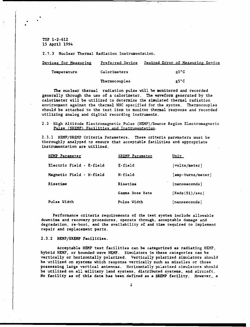
2.2.3 Nuclear Thermal Radiation Instrumentation.
Devices for Measurinz Preferred Device Desired Error of Measuring Device
Temperature Calorimeters ±5°C
Thermocouples ±50 C
The nuclear thermal radiation pulse will be monitored and recordedgenerally through the use of a calorimeter. The waveform generated by thecalorimeter will be utilized to determine the simulated thermal radiationenvironment against the thermal NHC specified for the system. Thermocouplesshould be attached to the test item to monitor thermal response and recordedutilizing analog and digital recording instruments.
2.3 High Altitude Electromagnetic Pulse (HEMP)/Source Region ElectromagneticPulse (SREMP) Facilities and Instrumentation.
2.3.1 HEMP/SREMP Criteria Parameters. These criteria parameters must bethoroughly analyzed to ensure that acceptable facilities and appropriateinstrumentation are utilized.
HEMP Parameter SREMP Parameter Unit
Electric Field - E-field E-field (volts/meter]
Magnetic Field - H-field H-field [amp-turns/meter]
Risetime Risetime [nanoseconds]
Gamma Dose Rate [Rads(Si)/sec]
Pulse Width Pulse Width [nanoseconds]
Performance criteria requirements of the test system include allowabledowntime and recovery procedures, operate through, acceptable damage anddegradation, re-boot, and the availability of and time required to implementrepair and replacement parts.
2.3.2 HEMP/SREMP Facilities.
Acceptable HEMP test facilities can be categorized as radiating HEMP,hybrid HEMP, or bounded wave HEMP. Simulators in these categories can bevertically or horizontally polarized. Vertically polarized simulators shouldbe utilized on systems which response vertically such as missiles or thosepossessing large vertical antennas. Horizontally polarized simulators shouldbe utilized on all military land systems, distributed systems, and aircraft.No facility as of this date has been defined as a SREMP facility. However, a

TOP 1-2-61215 April 1994
gamma dose rate facility, the HERMES III facility located at Sandia NationalLaboratories (SNL), Albuquerque, NM, is currently being utilized for this typeof tebting. Examples of acceptable facilities are the following:
Facility Type / Polarization Location Comments
1. USA WESTA Bounded Wave Array/ WSMR, NM Max E-Field - 65 kV/mHorizontal Area - 13.4 x 13.4 x 15.5h
metersQSTAG 244, Ed. 3System level
2. DNA ARES Bounded Wave/Vertical KAFB, NM Max E-Field - 97 kV/mArea - 40 x 33 x 40h mQSTAG 244, Ed. 3 orMIL-STD 2169A(Approx.)System level
3. USA WSMR Radiating/Horizontal KAFB, NM E-Field at 30 m - 35 kV/mHPD Area - 76 m Diameter
QSTAG 244, Ed. 3
Distributed system level
4. USA WSMR Radiating/Vertical KAFB, NM E-Field at 50 m - 70 kV/mVPD Area - 100 m Diameter
QSTAG 244, Ed. 3System level
5. USA WSMR Bounded Wave/Vertical KAFB, NM Max E-Field - 75 kV/mALECS Area - 25 x 13 7 x 12.5h m
QSTAG 244, Ed. 3System level
6. USA HPD-II Radiating,/Horizontal KAFB, NM Max E-Field - 65 kV/mArea - 76 m diameterQSTAG 244, Ed.4 orMIL-STD 2169ASystem level
7. HERMES-III SREMP SNL, NM System Level
Other HEMP facilities are listed in the DASIAC SR-90-252 on pages 4-5through 4-54. The PE must ensure that the HEMP test facility utilized is theforemost facility to a:curately simulate desired criteria and test systemresponse in order to adequately test the system configuration. More than onefacility may be required to adequately test a system to account for horizontaland vertical responses as well as SREMP effects. It is emphasized thatavailable facilities will provide only a simulated HEMP/SREMP environment.Therefore, in addition to good test data, adequate analysis must be performed
7

S
TOP 1-2-61215 April 1994
to account for the facility deficiencies which must be known, quantified, and
documented.
2.3.3 HEMP/SREMP Instrumentation/Dosimetry.
Devices for Measur•in Preferred Device Desired Error of Measurina Device
1. Current Current Probes ± 5 %
2. E-Field D-Dot Probe ± 5 %
3. H-Field B-Dot Probe ± 5 %
4. Gamma Dose CaF2 (Mn) ± 10 X
5. Gamma Dose Rate Compton Diode ± 10 %
The data acquisition system for the free-field tests should consist oftransient digitizers with an operating bandwidth of 250 MHz and 500 MHz (smalltest items), with a 1 Gigasample per second sampling rate. Fiber optic datatransmission system must be equal to the operating bandwidth. All utilizedprobes must be responsive to at least 1 GHz.
Measurements of each ill,Amination must be monitored by a B-dot probe(measures the time rate of change in the H-Field) or D-dot probe (measures thetime raLe of change in the E-Field) eo that the magnitude of the E-field andpulse shape information is obtained. This information should be digitized,analyzed, and stored for a later detailed analysis.
In the case of SREMP testing, the gamma dose and dose rate at selectedlocations on the test system will be measured using Calcium Fluoride ManganeseCaF 2 (Mn) Thermoluminescent Dosimeter (TLDs) and Compton diodes, respectively.The measured gamma dose values will be expressed in eGy(Si) and cGy(tissue) bythese general ratios, however the "Annual Book of ASTM Standards2 ", E666 andE668 must be referenced for each test:
cGy(Si)/cGy(CaFz ) - 1.02 and cGy(tissue)/cGy(CaF2 ) - 1.13, respectively.
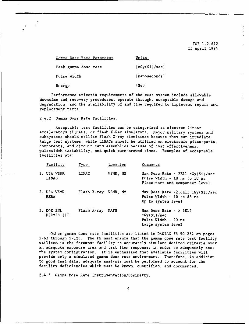
2.4 Gamma Dose Rate Facilities and Instrumentation.
2.4.1 Gamma Dose Rate Criteria Parameters. These criteria parameters must bethoroughly analyzed to ensure that acceptable facilities and appropriateinstrumentation are utilized.
Prompt gamma radiation pulses generate the production of chargecarriers and subsequent photocurrents. These damaging photocurrents whichflow across device junctions induce transient upset, latch-up and/or burnoutin the semiconductor devices.
8
TOP 1-2-612
15 April 1994
Gamma Dose Rate Parameter Units
Peak gamma dose rate [cGy(Si)/sec]
Pulse Width [nanoseconds]
Energy [Mev]
Performance criteria requirements of the test sya:em include allowableduwntime and recovery procedures, operate through, acceptable damage anddegradation, and the availability of and time required to implement repair andreplacement parts.
2.4.2 Gamma Dose Rate Facilities.
Acceptable test facilities can be categorized as electron line&raccelerators (LINAC), or flash X-Ray simulators. Major military systems andsubsystems should utilize flash X-ray simulators because they can irradiatelarge test systems; while LINACs should be utilized on electronic piece-parts,components, and circuit card assemblies because of cost effectiveness,pulsewidth variability, and quick turn-around times. Examples of acceptablefacilities are:
Facility Tve Location Comments
1. USA WSMR LINAC WSMR, NM Max Dose Rate - 2E11 cGy(Si)/secLINAC Pulse Width - 10 ns to 10 As
Piece-part and component level
2. USA WSMR Flash X-ray WSMR, NM Max Dose Rate -2.6E11 cGy(Si)/secREBA Pulse Width - 50 to 85 ns
Up to system level
3. DOE SNL Flash X-ray KAFB Max Dose Rate - > 5E12HERMES III cGy(Si)/sec
Pulse Width - 20 nsLarge system level
Other gamma dose rate facilities are listed in DASIAC SR-QO-252 on pages5-63 through 5-128. The PE must ensure that the gamma dose rate test facilityutilized is the foremost facility to accurately simulate desired criteria overan adequate exposure area and test item responses in order to adequately cestthe system configuration. It is emphasized that available facilities willprovide only a simulated gamma dose rate environment. Therefore, in additionto good test data, adequate analysis must be performed to account for thefacility deficiencies which must be known, quantified, and documented.
2.4.3 Camma Dose Rate Instrumentation/Dosimetry.
9

TOP 1-2-61215 April 1994
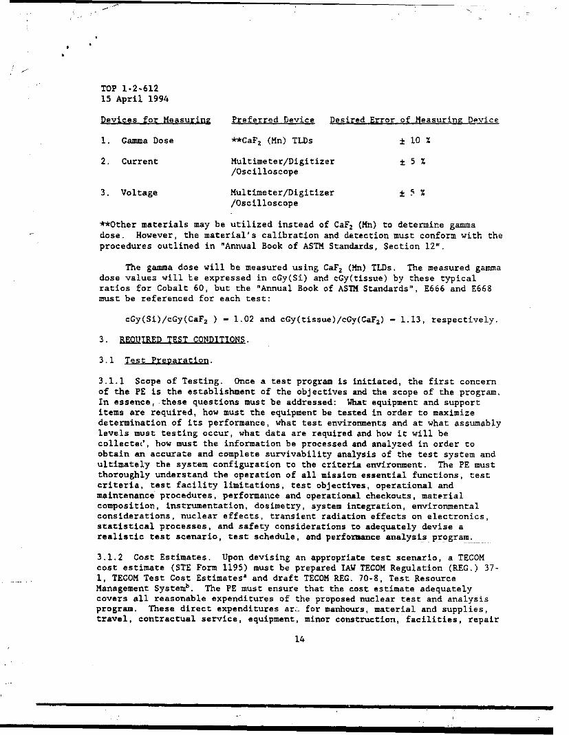
Devices for Measuring Preferred Device Desired Error of Measuring Device
1. Photocurrent Photocurrent Probes ± 5 %
2. Gamma Dose **CaF2 (Mn) lDs ± 10 %
3. Gamma Radiation PIN Diode ± 10 %Pulse Compton Diode ± 10 %
4. Current Multimeter/Digitizer ± 5 %/Oscilloscope
5. Voltage Multimeter/Digitizer ± 5 %/Oscilloscope
** Other materials may be utilized instead of CaFZ (Mn) to determine gammadose. However, the material's calibration and detection must conform with theprocedures outlined in "Annual Book of ASTM Standards, Section 12".
The gamma dose is generally measured using CaF2 (Mn) TLDs. The measuredgamma dose values will be expressed in cGy(Si) and cGy(tissue) by thesegeneral ratios, but the "Annual Book of ASTN Standards", E666 and E668 must bereferenced for each test:
cGy(Si)/cGy(CaF2 ) - 1.02 and cGy(tissue)/cCy(CaF2 ) - 1.13, respectively.
Each radiation pulse will be measured using a PIN or Compton diode anddigitized on a transient digitizing system. The pulsewidth (FWHM) of eachradiation pulse will be obtained from this digitized signal. The gamma doserate for each pulse will then be determined from the dose recorded on the TLDsand divided by the pulsewidth obtained from the digitizers.
2.5 Neutron Fluence Facilities and Instrumentation.
2.5.1 Neutron Fluence Criteria Parameter. This criteria parameter must bethoroughly analyzed to ensure that acceptable facilities and appropriateinstrumentation are utilized.
Fast neutrons interact with semiconductor material in electronic piece-parts by elastic collisions with lattice atoms which decrease minority carrierlifetimes and increase device resistivity. This resulting damage alterselectrical parameters of the device which can cause failure in thesemiconductor devices or circuit applications.
Neutron Fluence Parameter Units
Neutron Fluence 11 Mev(Si) n/cm2 ]
Performance criteria requirements of the test system include allowable
10

TOP 1-2-61215 April 1994
downtime and recovery procedures, operate through, acceptable damage anddegradation, and te availability of and time required to implement repair andreplacement parts.
2.5.2 Neutron Fluence Facilities.
Acceptable test facilities can be -ategorized as either a Fast BurstReactor (FBR) or a TRIGA reactor. (Sometimes, Californium-252 is utilized forpiece-part testing.) These reactors generally can be utilized in the pulse orsteady-state mode of operation. In the pulse mode of operation, the FBR cangenerate neutron fluence up to 5E14 n/cm2 with energies > 10 keV and gammadose rate up to 1E9 cGy(Si)/sec with a pulsewidth of approximately 50 As.However, when total neutron fluence is the primary concern, the steady-statemode of operation is typically used. Examples of acceptable facilities are:
Facility T Location Comments
1. USA WSMR FBR WSMR, NM Peak Pulse Power - 6.5E4 MWFBR Neutron Fluence - 7E13 n/cm2
FWHM Pulse Width - 40 to 3000.tsUp to system level
2. USA APG FBR APG, MD Peak Pulse Power - lE5 MWAPRF Neutron Fluence - 5E14 n/cm2
FWHM Pulse Width -50 As tolOmsUp to system level
Other neutron fluence facilities are listed in DASIAC SR-90-252 on pages5-42 through 5-62. The PE must ensure that the neutron fluence test facilityutilized is the foremost facility to accurately simulate desired criteria andtest item responses in order to adequately test the system configuration. Itis emphasized that available facilities will provide only a simulated neutronfluence environment. Therefore, in addition to good test data, adequateanalysis must be performed to account for the facility deficiencies which mustbe known, quantified, and documented.
2.5.3 Neutron Fluence Instrumentation/Dosimetry.
Devices for Measurinz Preferred Device Desired Measurement Accuracy
1. Neutron Fluence **Sulfur Activation Foil ± 10 %
2. Gamma Dose **CaF2 (Mn) TLDs ± 10 %
** Other materials or techniques may be utilized instead of sulfur and CaF2(Mn) to determine neutron fluence and gamma dose, respectively. However, thematerial's calibration and detection must conform with the procedures outlinedin "Annual Book of ASTM Standards, Section 12".
11

TOP 1-2-612
15 April 1994
Devices for Measuring Preferred Device Desired Measurement Accuracy
3. Current Multimeter/Digitizer ± 5 %/Oscilloscope
4. Voltage Multimeter/Digitizer ± 5 %/Oscilloscope
The neutron fluence at each test location will be measured using sulfuractivation foils which measure neutrons with energies greater that 3 MeV; but,the "Annual Book of ASTM Standards", E720, E721, and E722 must be referenced.The measured fluence will be converted to 1 MeV(Si) equivalent damage fluenceby the following relationship:
1 MeV(Si) eq. neutron fluence - K * ( 3 MeV neutron fluence )
where K is experimentally determined with respect to many factors, such asenergy, spectrum, and source-co-target distance.
The gamma dose will be measured using CaF2 (Mn) TLDs. The measured gammadose values will be expressed in cGy(Si) and cGy(tissue) by these typicalratios, but the "Annual Book of ASTM Standardsm, E666 and E668 must bereferenced for each test:
cGy(Si)/cGy(CaF2 ) - 1.02 and cGy(tissue)/cGy(CaF2 ) - 1.13, respectively.
2.6 Total Gamma Dose Facilities and Instrumentation.
2.6.1 Total Gamma Dose Criteria Parameter. This criteria parameter must bethoroughly analyzed to ensure that acceptable facilities and appropriateinstrumentation are utilized.
Total gamma dose generates hole-electron pairs through the process ofionization in the semiconductor material resulting in trapped charges. Thesetotal dose effects are exhibited either as a change in electrical parametersor as a catastrophic failure in semiconductor devices.
Total Gamma Dose Parameter Units
Total Gamma Dose [cGy(Si)]
Obtaining the proper total gamma dose test criterion can be difficult.The PE must first obtain NHC and the identify the subheading: "SiliconAbsorption/Displacement Damage". Under this subheading, is the title " MaxCombined Neutron and Gamma Ionizing Dose, (cGy(Si))" referred to as.Di. Withthis value of Di, the PE must subtract the nPutron dose contribution. Thisacquired value is the actual Center-Of-Mass (COM) total gamma dose to bereceived by the test item.
12

S
TOP 1-2-61215 April 1994
Performance criteria requirements of the test system include allowabledowntime and recovery procedures, operate through, recovery time, degradationand/or acceptable damage, and the availability of and time required toimplement repair and replacement parts.
2.6.2 Total Gamma Dose Facilities,
Acceptable test facilities typically utilize a Cobalt-60 source ormultiple Cobalt-60 sources. Large systems are extremely difficult to testadequately because no large scale DOD /DOE gamma dose facility is available.Therefore, most testing should be accomplished at the piece-part, 'component,LRU, and subsystem level. Whole Jody irradiations are typically limited tosurfaces < 1.5 m on a side for gradient and disposition rate reasons.Examples of acceptable facilities are:
Eacility Location Comments
1. USA WSMR WSMR, NM Max Dose Rate - 1700 cGy(Si)/secGRF Exposure Area - 13 x 6 x 4 height m
8 SourcesPiece-part, Component, LRU, subsystem andsystem level
2. USA APG APG, MD Max Dose Rate - 600 cCy(Si)/secAPRF Exposure Area - 15.2 cm Dia. x 20.3 height cm
Piece-part, Component, small LRU/subsyscemlevel
3. USA ARL Adelphi, MD Max Dose Rate - 215 cGy(Si)/secCobalt-60 Exposure Area - 9.5 cm Dia. x 25 height cmFacility Piece-part, Component, very small LRU/
subsystem level
Other total gamma dose facilities are listed in DASIAC SR-90-252 on pages5-9 through 5-41. The PE must ensure that the total gamma dose test facilityutilized is the foremost facility to accurately simulate desired criteria overan adequate exposure area and test item responses in order to adequately testthe system configuration. It is emphasized that available facilities willprovide only a simulated total gamma dose environment. Therefore, in additionto good test data, adequate analysis must be performed to account for thefacility deficiencies which must be known, quantified, and documented.
2.6.3 Total Gamma Dose Instrumentation/Dosimetry.
13
TOP 1-2-61215 April 1994
Devices for Measuring Preferred Device Desired Error of Measuring Device
1. Gamma Dose **CaF2 (Mn) TLDs ± 10 %
2. Current Multimeter/Digitizer ± 5 %/Oscilloscope
3. Voltage Multimeter/Digitizer ± 5 %/Oscilloscope
**Other materials may be utilized instead of CaF2 (Mn) to determine gammadose. However, the material's calibration and detection must conform with theprocedures outlined in "Annual Book of ASTM Standards, Section 12".
The gamma dose will be measured using CaF2 (Mn) TLDs. The measured gammadose values will be expressed in cGy(Si) and cGy(tissue) by these typicalratios for Cobalt 60, but the "Annual Book of ASTM Standards", E666 and E668must be referenced for each test:
cGy(Si)/cGy(CaF 2 ) - 1.02 and cGy(tissue)/cGy(CaF2 ) - 1.13, respectively.
3. RUMIRED TEST CONDITIONS.
3.1 Test Preparation.
3.1.1 Scope of Testing. Once a test program is initiated, the first concernof the PE is the establishment of the objectives and the scope of the program.In essence, these questions must be addressed: What equipment and supportitems are required, how must the equipment be tested in order to maximizedetermination of its performance, what test environments and at what assumablylevels must testing occur, what data are required and how it will becollectet', how must the information be processed and analyzed in order toobtain an accurate and complete survivability analysis of the test system andultimately the system configuration to the criteria environment. The PE mustthoroughly understand the operation of all mission essential functions, testcriteria, test facility limitations, test objectives, operational andmaintenance procedures, performance and operational checkouts, materialcomposition, instrumentation, dosimetry, system integration, environmentalconsiderations, nuclear effects, transient radiation effects on electronics,statistical processes, and safety considerations to adequately devise arealistic test scenario, test schedule, and performance analysis program.
3.1.2 Cost Estimates. Upon devising an appropriate test scenario, a TECOMcost estimate (STE Form 1195) must be prepared IAW TECOM Regulation (REG.) 37-1, TECOM Test Cost Estimates' and draft TECOM REG. 70-8, Test ResourceManagement Systemb. The PE must ensure that the cost estimate adequatelycovers all reasonable expenditures of the proposed nuclear test and analysisprogram. These direct expenditures arg for manhours, material and supplies,travel, contractual service, equipment, minor construction, facilities, repair
14

TOP 1-2-612
15 April 1994
and replacement of test related consumables. Additionally, a small percentageof the total funding should be allotted for contingencies because of facilityand test system related problems that almost always occur.
3.1.3 Test Coordination. From the initiation to the completion of the rest"program, test coordination is a constant and essential task. The PE mustcoordinate effectively with a multitude of various personnel in order toproperly prepare, execute, and determine the nuclear survivability of a testsystem. Without proper and effective test coordination, a NSA program willexperience cost overruns, unnecessary test delays, inadequate test data,improper determinations, and improper usage of manpower. In conclusion, testcoordination is one of the most important aspects to project engineering andis essential to the conduct of a successful NSA program.
3.1.4 Environmental Impact. An important pretest requirement lAW ArmyRegulations (AR) AR 200-1, Environmental Protection and Enhancement', and AR200-2, Environmental Effects of Army Actionsd, is an environmental analysis.This analysis will help alleviate environmental problems that could interferewith the test schedule and completion of the NSA program. The proper"documents must be completed and submitted to the environmental office and/orpersonnel who regulate and control environmental practices at the testexecution site prior to start-of-test. The actual time requirement fordocument submission before test execution, is dependent on the level ofpreparation required, type of system, and required documentation as well asthe workload of the environmental office. Most of the required informationcan be obtained from the PM's office.
3.1.5 Safety Analysis. Another important pretest coordination task is thesafety analysis which must be prepared lAW AMC-R 385-100, Safety Manual*.Like the environmental analysis, it should be prepared, submitted, andapproved As Soon As Possible (ASAP) to alleviate safety problems which couldaffect the completion of the NSA program. The safety analysis can usually beobtained from the PM's office or system's contractor. If a complete initialsafety analysis is needed, extra time and funds must be allotted to identifythe necessary safety procedures and prepare the documentation.
3.1.6 Preferred Nuclear Environment Test Methodology. The PE must ensurethat sufficient analysis is performed to account for deficiencies in thesimulated nuclear test environment versus the United States Army Nuclear andChemical Agency (USANCA) environments, variations between the test andproduction configuration, and the corresponding variations in hardwareresponse. One must initially assume that neither the test environment orhardware are accurate representations of the NHC and system configuration,respectively. There will be differences which must be identified andquantified in order that a survivability analysis can be successfullyperformed. To accurately achieve compliance with the test objective, one mustaccomplish the following:
15
____________________________________________________________/ ',

TOP 1-2-61215 April 1994
First, ;erform the pretest analysis to identify:
a. Instrumentation and dosimetry for required response and environmentdata.
b. Test hardware for each environment.
c. Location of instrumentation and dosimetry.
d. Test facilities and limitations.
e. Test levels per environment.
f. Test system's performance and operational checkouts to adequatelyanalyze all mission essential functions.
g. Required test data per environment.
h. Safety margins of Hardened Critical Items (HCIs).
i. Electromagnetic (EM) energy paths and port-of-entries.
J. Potential test system's responses.
k. Potential susceptibilities and hardness levels in all nuclearenvironments with respect to the USANCA criteria.
1. Test system's configuration with respect to each environment.
m. Test system's configuration baseline.
n. Differences between test and production configuration.
Second, the PE must thoroughly document and analyze the test hardwarewhich is to be utilized during the NSA. This documentation and determinationincludes the test system's material composition, shape, size, mass, fasteningschemes, shielding and attenuation characteristics, nuclear hardening conceptsand devices, mission essential functions, and HCIs and circuits. Then, the PEmust analyze the test hardware relative to fielded or proposed fielded systemhardware and identify all of the relevant differences. With all thisinformation, the PE can identify and establish the test system and proposedsystem baseline configuration. This baseline will be utilized for thesurvivability analysis as well as a basis for analysis of all productimprovements, Engineering Change Proposals (ECPs), and configuration changesto ensure that the test system remains nuclear survivable during production,maintenance, and deployment.
Third, the PE must identify the environmental tests that will best meetthe requirements identified in the pretest analysis. The nuclear test
16
//
TOP 1-2-61215 April 1994
environments are Nuclear Airblast, Nuclear Thermal Irradiation, EMP(Endoatmospheric (SREMP) and Exoatmospheric (HEMP)) and Initial NuclearRadiation (INR) (gamma dose rate, total gamma dose, and neutron fluence). AllINR testing should be conducted in the following sequence: gamma dose rate,neutron fluence, and total gamma dose. This sequence is based on actualoccurrence and the fart that some semiconductor devices may generateinaccurate failure thresholds if this acknowledged sequence is not preserved.If time constraints or test facility scheduling forces the PE to deviate fromthis INR test sequence, analysis must be performed to insure that any out-of-sequence related effects on the test system are identified and accounted for.Testing conducted in the EMP, nuclear airblast, and nuclear thermal radiationenvironments can usually be performed independently with disregard to the testsequence because of the nature of their effects. However, HEMP is preferredafter airblast and thermal because: HEMP is produced by an exo-atmosphericdetonation and can occur after a surface/near-surface event, and the responseof the damaged test item is likely to be more adverse. Synergistic effects onthe test system, particularly for thermal and airblast, must be determinedbecause it is real and may significantly enhance damage.
Lastly, the PE must analyze and determine the test system's performancewith a deta-led post-test analysis. This post-test analysis includes testenvironments and results of the pretest analysis, documentation and detaileddetermination of the test system's performance, determination of allshortcomings and failures, and determination uf obtained environmental dataagainst the USANCA criteria. In order to effectively determine criteriacompliance, the PE must thoroughly understand the simulation fidelity of eachtest facility. All test facilities have one or more parameter deficiencies;therefore, these deficiencies must be well understood and analysis performedto establish the effects of these parameter deficiencies on the results of thetest. With this analysis, the PE can adequately determine the environmentaltest parameters against the desired USANCA criteria. In order to effectivelyanalyze survivability of the system configuration, the PE must thoroughlyunderstand the differcnces between the test system's and the system'sconfiguration, and corresponding effects on the analyzed system. Combinedwith the piece-part/circuit analysis, pretest analysis or other analyticaldata, the PE will then be able to analyze the survivability of the system'sconfiguration to the USANCA requirements.
3.1.7 Test Plan. The PE must incorporate all the factors and ideas presentedin paragraphs 3.1.1 through 3.1.6 into a test plan that must be written IAWTECOM Pamphlet (Pam) 73-l'. T1 e test plan must be developed by the PE,submitted to TECOM approximately sixty days prior to, and approved by TECOMapproximately thirty days prior to test execution. Test plans should containthe following information:
I. Sectior 1: Introducin
1.1 Test Objective.1.2 Test t•uthority.1.3 Test Concept.
17

TOP 1-2-61215 April 1994
1.4 System Description.1.5 Unique Test Personnel Requirements.II. Section 2: Subtests. (for each test environment).2.1 Name of Subtest.2.1.1 Objectives.2.1.2 Criteria.2.1.3 Test Procedures.2.1.4 Data Required.2.1.5 Data Analysis/Procedure.
III. Section 3: Appendices.A. Test Criteria.B. Test Schedule.C. Informal Coordination.D. References.E. Abbreviations.F. Distribution List.
Events are likely to occur during the test execution that causes the PEto utilize sound engineering judgement to deviate from the original test plan.Major deviations must be approved by HQ TECOM before implemented. Alldeviations must be documented in the detailed test report.
3.2 Test Execution.
3.2.1 Pretest Analysis/Modeling. Before the execution of any nuclear testprogram, a pretest analysis must be performed. During the pretest analysis,the PE must thoroughly examine the test system and manipulate engineeringprincipals and nuclear effects responses to estimate where potential nuclearsurvivability problems exist. The PE must also determine test facilities toensure that the best facility is scheduled, sufficient data acquisition isavailable and scheduled, and requirad test configurations/orientations can betested. In order to perform an adequate pretest analysis, the PE must haveaccurate schematics, part lists, details of deliberate hardening methods/hardware, previous test and/or analytical data, material composition, wiringdiagrams, cable shielding details, and piece-part specifications. Based onthe pretest analys~s, the PE can establish functional models where significantdata can be obtained on the expected performance of the test system throughall the different nuclear environments.
3.2.2 Piece-Part/Circuit Analysis Program. One of the major limitations inNSA programs is tue difficulty of establishing survivability confidences onsystems with extremely small sample sizes. To effectively establishconfidence levels, and, hence, the survivability of the baseline system, thePE must consider an analysis program. For INR, this program will use piece-part test data, circuit analysis, modelling methods, and statisticalprocedures to determine design margins and confidence levels. The piece-part/circuit analysis program will identify all potential nuclear survivabilitydeficiencies by accounting for response variances due to differentmanufacturing processes. For EMP, this program will identify and analyze
18
I
TOP 1-2-61215 April 1994
grounding schemes, cabliing, cable shielding, transient and terminal protectiondevices. For airblast and thermal analysis, the material composition, shape,size, mass, and fastening schemes are analyzed. Only by having adequatedesign margins in all nuclear survivability environments, can an acceptableairblast, thermal, HEMP, and/or INR survivability analysis be performed on thesystem's baseline configuration.
3.2.3 Test Organization and Documentation. The formulation of a detailedtest plan and effective test coordination prior to the test execution iscritical to test organization and execution, and cost effectiveness. Testorganization consists of a set of preset procedures for accomplishing specifictest execution tasks. Proper test organization will result in superior tf•stexecution. The PE must assign and explain to each test support personneltheir specific tasks and schedules. Examples include test system anddosimetry placement, probe placement, test documentation, data acquisition,performance checkouts, maintenance procedures, etc. The most important ofthese specific tasks is test documentation. The PE must ensure that allaspects of the nuclear test program are carefully, completely, and co':::ectlydocumented. To achieve effective documentation, test specific contrcl formsshould be generated. Improper documentation can lead to an inaccurate andincomplete NSA. In conclusion, careful organization and adequatedocumentation of the test is essential.
3.2.4 Sound Engineering Judgement. During the entire execution of the test,the PE must utilize sound engineering judgement to effectively test andanalyze the test item and maintain schedules and costs. Sound engineeringjudgement becomes extremely critical when schedule impa~ts occur such asfacility downtime, inclement weather, failures and/or re-priorization. Undersuch conditions, the PE must determine the problem, deviate from the originaltest plan, and devise an alternate plan or set of procedures. The PE mustalso devise work-arounds that maximize completion of testing and testobjectives.
3.3 Test Revortinz and Life-Cycle.
3.3.1 Data Reduction and Analysis. After the completion of all survivabilitytesting, the PE must conduct data reduction and analysi. on the raw data. Theraw test data are manipulated into an understandable format and documented inAppendix B and summarized in the Test Results section o:. the test report. Theactual data reduction procedures selected are dependent on performanceparameters, the test en'ironment, and the criteria parameters. All datareduction procedures must be standardized for each individual test anddocumented. Clear and concise data reduction and analysis will enhance andenrich the final product, the survivability analysis.
3.3.2 Statistical and Error Analysis. Other forms of analysib that should beperformed on the test data are statistical and error analysts. The PE shoulduse statistical analysis to obtain the nuclear survivability probability ofelectronic piece-parts based on test data, circuit analysis, and safety
19

TOP 1-2-61215 April 1994
margins. The preferred probability with confidence is 99/90 tolerance level(0.99 probability of survivable with a 90 percent confidence). Also,statistical analysis should be utilized to obtain the criteria compliancebetween actual environment parameters and desired criteria. An error analysisshould be performed to account for and eliminate sources of error present inthe raw test data. Possible sources of error are: instrumentation and dataacquisition, human, test setup, probe, dosimetry, and roundoff. The PEutilizes this error analysis to help predict how accurate the simulated testenvironment was to the specified USANCA environment and to ensure that testsystem received its nuclear survivability criteria taking the predicted errorinto account.
3.3.3 Survivability Analysis of the System Configuration versus USANCACriteria. Based on data processed (system and environmental), the PE analyzesnuclear survivability of the test system to each test environment. The PEthen proceeds to analyze the nuclear survivability of the system'sconfiguration to each of the USANCA environments. To accomplish this, the PEmust first identify and define the test system's configuration, testenvironments, and safety margins. The PE then uses this informaUton toestablish nuclear survivability of the test system configuration to the testenvironments. The test results and environments are then corrected torepresent the USANCA environments by accounting for differences anddeficiencies. Finally, the PE analyzes the baseline system configurationperformance against the corrected or USANCA environments. This is the NSA ofthe baseline configuration and is the information for the Technical Analysisof the test report. Also, the system's baseline configuration and analysis isthe basis for analyzing effects of product improvements or other systemconfiguration changes or repairs on the hardness level and survivability ofthe system during its lifetime. These future analyses will involve additionalpiece-part/:ircuit analysis and piece-part testing where data are notavailable.
3.3.4 Test Reports. After the PE has completed all test execution, dataanalyses, and survivability analysis, a detailed test report must be writtenlAW TECOM Pxm 73-1. The test report must be completed and submitted to TECOMNT.T javenty days after test completion and approved by TECOM NLT thirty daysafter submission. Test reports should contain the following information:
Foreword.I. Section 1: Executive Digest.
1.1 Summary.1.2 Test Objective.1.3 Testing Authority.1.4 Test Concept.1.5 System Description.1.6 Conclusions.1.7 Recommendations.II. Section 2: Subtests. (for each test environment).2.1 Name of Subtest.
20
/
TOP 1-2-61215 April 1994
2.1.1 Objectives.2.1.2 Criteria.2.1.3 Test Procedure.2.1.4 Test Findings.
a. Test Results.b. Analytical Procedure.
2.1.5 Technical Analysis.a. Significance of Test Results.b. Criteria Compliance.
III. Section 3: Appendices.A. Test Criteria.B. Test Data.C. Preliminary Determination of Deficiencies, Shortcomings, and
Suggested Improvements.
Other necessary appendices may be included at the option of the author orif specified in the test directive.
The following appendices are required and closc in order the test report:
References.Abbreviations.Distribution List.
The highlighted portions of the previous list (Summary, Test Findings, &Technical Analysis) are the most significant sections of the test report. ThePE must give special considaration to ensure these sections are concise,detailed, complete, accurate and comprehensible.
3.3.5 Life-Cycle Nuclear Survivability Program. The production, operation,maturity, storage, maintenance, modification, and ambient environments mustnot introduce any form of susceptibilities or unacceptable levels ofdegradation into a nuclear sur-ivable system. To ensure continued nuclearsurvivability, a Life-Cycle Nuclear Survivability (LCNS) program must beestablished lAW the NHC, Army Regulation (AR) 70-604, and the Department ofDefense Instruction (DODI) 5000.25. The basic purpose of the LCNS program isto control all changes to thm baseline configuration during production andproduct improvements, ensure that an acceptable hardness level is preservedduring maintenance by using certified spare parts and procedures, andverifying that the hardness level is not degraded to an unacceptable levelduring fielding, storage, and operating in the ambient environments.
3.4 Nuclear Airt Last Pretest Analysis. During the pretest analysis, the PEmust analyze and identify the high risk susceptibilities and test conditionsof the test system to the airblast environment. To do this, the PE musteffectively:
a. Identify potentially susceptible subsystems and/or system componentsbased upon exposure conditions, materiel composition, shape, size, mass, and
21
/
TOP 1-2-612
15 April 1994
fastening schemes.
b. Identify test system's configuration.
c. Define data acquisition requirements
d. Analyze contractor's program documentation.
e. Analyze hardening and analysis performed by contractor.
f. Define baseline performance checks for test hardware.
g. Identify the most realistic and severe test configuration andorientation with respect to GZ or the source.
h. Identify the type, number, and location of gages to measure responseof areas of concern.
i. Analyze potential test facilities to determine the one best for testsystem or test item(s).
J. Analyze selected test facility's response producing parameters andcalculate the expected system response utilizing engineering principals.
k. Perform structural analysis of mechanical and structural response ofthe test system and of mission critical external fixtures/appendages to thetransient loads induced by the blast wave utilizing finite tlement methods orsimilar analytical techniques.
1. If appropriate, perform an overturn analysis using TRUCK or a similarcode.
m. Identify detailed photography scheme.
3.5 Nuclear Thermal Radiation Pretest Analysis. During the pretest analysis,the PE must analyze and identify the high riik susceptibilities and testconditions of the test system to the thermal radiation environment. To dothis the PE must effectively:
a. Identify potentially susceptible subsystems and/or system components
based upon exposure conditions, materiel composition, shape, size, and mass.
b. Identify test system's configuration.
c. Define data acquisition requirements
d. Analyze contractor's program documentation.
e. Analyze hardening and analysis performed by contractor.
22
TOP 1-2-612
15 April 1994
f. Define baseline performance checks for test hardware.
g. Identify the most realistic and severe test configuration andorientation with respect to the thermal radiation source.
h. Identify the type, number, and location of gages to measure responseof areas of concern.
i. Analyze potential test facilitiep tc determine the one best for testsystem or test item(s). More than one may be required.
J. Analyze selected test facility's response producing parameters andcalculate the expected system's thermal response utilizing engineeringprincipals.
1. Define and document all pretest visual inspections and quantifiedperformance check baselines.
m. Identify detailed photography scheme on all exposure areas.
3.6 HEMP/SRFMP Pretest Analysis. During the pretest analysis, the PE mustanalyze and identify the high risk susceptibilities and test conditions of thetest system to the HEMP/SREMP environments. To do this the PE musteffectively:
a. Analyze drawings and circuits to determine potentially harmful energypaths. The analysis should be concentrated on external unshielded cables ofsignificant length and interface of these cables into subsystems of the testsystem.
b. Identify test system's configuration.
c. Identify and determine all point-of-entries.
d. Analyze grounding scheme and shielded cables to include backshellsand connectors for shielding effectiveness.
e. Determine inherent hardness afforded by the system to its missioncritical electronics.
f. Define data acquisition requirements.
g. Analyze contractor's program documentation.
h. Analyze hardening and analysis performed by contractor.
i. Define baseline performance checks for test hardware.
J. Utilize peak pulse power data to analyze the piece-part and terminal
23
TOP 1-2-61215 April 1994
protection devices (TPDs) that are inputs to these large energy paths.
k. Fabricate Breakout Boxes (BOBs) for all cables of concern to enableactual pin measurements to be performed during testing and current injection.
1. Analyze potential test facilities to determine the one best for thetest system or its test item(s).
m. Identify the type and location of current and differontial voltageprobes to be utilized to measure predicted cables and pins of concern.
n. Identify all test orientations.
0. Identify test levels based on results of hardening determination.
p. Identify all test configurations and operating modes.
q. Identify the location for all dosimetry (SREMP).
3.7 GA.usa Dose Rate Pretest Analysis. During the pretest analysis, the PEmust analyze and identify high risk HCI's and test conditions of the testsystem to the ga-a dose rate environment. To accomplish this, the PE musteffectively:
a. Identify all HCIs based upon technology. Consider existing circuithardening in this screcning.
b. Identify test system's configuration.
c. Define data acquisition requirements.
d. Analyze contractor's program documentation.
e. Analyze hardening and analysis performed by contractor.
f. Define baseline performance checks for test hirdware.
g. Analyze potential test facilities to determine the one best for thetest system and/or its test item(s). At least two different facilities willlikely be required - one for piece-parts/components and one for LRUs and/orsystems.
h. Identify the most realistic and severe test setup/circuit withrespect to the radiation exposure.
i. Identify all current limiting, power removal, and/or gamma dose rate'4 hardening applications.
J. Identify the type, number, and location for all dosimetry and data
24
TOP 1-2-612
15 April 1994
acquisition required to collect real time response data.
k. Establish the baseline configuration of the test system.
1. Identify test orientations.
m. Identify test levels based on results of hardening determination.
n. Identify test configurations and operating modes.
o. Acquire test data for all high priority HCIs.
p. Analyze all HCI circuit performance characteristics.
q. Determine HCI safety margins based upon test data, circuit analysis,and statistical techniques.
r. Analyze potential for Dose Enhancement Effects.
3.8 Neutron Fluence Pretest Analysis, During the pretest analysis, the PEmust analyze and identify high risk HCIs and test conditions of the testsystem to the neutron fluence environment. To accomplish this, the PE musteffectively:
a. Identify HCIs based upon technology.
b. Identify test system's configuration.
c. Define data acquisition requirements.
d. Analyze contractor's program documentation.
e. Analyze hardening and analysis performed by contractor.
f. Define baseline performance checks for test hardware.
g. Analyze potential test facilities to determine the one best for thetest system and/or its test item(s).
h. Identify the most realistic and severe test setup with respect to theneutron source.
i. Identify the type, number, and location for all dosimetry and dataacquisition required to collect real time response data.
J. Establish the baseline configuration of the test system.
k. Acquire test data for all high priority HCIs.
23
TOP 1-2-61215 April 1994
1. Analyze all HCI circuit -,'rformance characteristics.
m. Determine HCI safety margins based upon test data, circuit analysisand statistical techniques.
n. Identify test orientations with respect to the neutron source.
o. Identify test levels based on results of the hardening determination.
p. Identify test configurations and operating modes.
q. Asses potential for Dose Enhancement Effects.
3.9 Total Gamma Dose Pretest Analysis. During the pretest analysis, the PEmust analyze and identify high risk HCIs and test conditions of the testsystem to the total gamlaa dose environment. To accomplish this, the PE musteffectively:
a. Identify HCIs based upon technology.
b. Identify test system's configuration.
c. Define data acquisition requirements.
d. Analyze contractor's program documentation.
e. Analyze hardening and analysis performed by contractor.
f. Define baseline performance checks for test hardware.
g. Analyze potential test facilities to determine the one best for thetest system and/or its test item(s).
h. Identify the most realistic and severe test setup with respect to theradiation source.
i. Identify circumvention and/or total gamma dose hardening techniques.
J. Identify the type, number, and location for all dosimetry and dataacquisition required to collect real time response data.
k. Establish the baseline configuration of the test system.
1. Identify test orientations for exposure.
m. Identify test configurations and operating modes.
n. Identify test levels based on results of hardening determination.
26

TOP 1-2-612
15 April 1994
o. Acquire test data for all high priority HCIs.
p. Analyze all HCI circuit performance characteristics.
q. Determine HCI safety margins based upon test data, circuit analysisand statistical techniques.
r. Analyze potential for Dose Enhancement Effects.
4. TEST PROCEDURES.
4.1 Nuclear Airblast.
4.1.1 General.
4.1.1.1 Test System. Survivability of the test hardware when exposed to theairblast test environment will be analyzed by:
a. Performing a detailed pretest analysis.
b. Ensuring that the test hardware is properly deployed and in arealistic operational state and configuration as established by the pretest
analysis.
c. Establishing the performance baseline of the test hardware prior tothe event.
d. Determining effects by visual inspections, performance of thebaseline checks, and detailed failure diagnosis.
e. Determining performance/operational data of the test hardware.
f. Analyzing both still and high speed motion photography of the testhardware taken before, during, and after the airblast event.
g. Analyzing response measurements from instruments such asacceleration, pressure, and strain gages.
h. Determining damage and/or degradation in regards to impacts on
mission accomplishment.
i. Analyzing test environment data.
4.1.1.2 Baseline System. The survivability of the baseline systemconfiguration when exposed to the airblast USANCA environments will beanalyzed by:
a. Analyzing the differences between the test and USANCA environments.
27
TOP 1-2-61215 kpril 1994
b. Analyzing the differences between the test and baselineconfigurations.
c. Determining the response of the baseline configuration to the USANCAenvironment.
4.1.2 Test Setup. The test setup is based upon results obtained from thepretest analysis and should consist of:
a. Position the test hardware at the desired test location and in thecorrect test configuration.
b. Prior to the event, the complete test hardware must be examined toensure proper operation and establish the performance baseline.
c. Instrument the test hardware IAW the pretest analysis to acquirecritical response data of the test hardware. Instrumentation includespressure transducers, accelerometers, and strain gages. Ensureinstrumentation is calibrated.
d. Photograph the pretest setup to include instrumentation locations.
e. Setup, check, and calibrate the complete data acquisition system.Check the cables to ensure adequate attachment to the transducers, datarecorders, and amplifiers; and that they are sufficiently protected againstthe blast wave. Set-up amplifiers and transient digitizers lAW predictions ofthe pretest analysis. All data acquisition calibration should be accomplishedat the test location to ensure accuracy.
f. Setup, checkout, and calibrate backup data channels for criticalareas and responses.
g. Setup, checkout, and calibrate the pressure transducers to measurethe principal free-field environmental parameters.
h. Setup the high speed motion cameras to record the response of thetest hardware during the event. Typical speeds are 250 and 400 Frames PerSecond (fps).
i. Ensure the test hardware is in the proper operational mode for thetest.
4.1.3 Test. After the airblast environment has been produced and the testarea is considered safe, a comprehensive damage analysis must be performed onthe test hardware. This damage analysis will consist of post-eventphotography, a detailed visual inspection, displacement measurements, andcomplete post-event performance/operational checks. Response data obtain frompressure transducers, accelerometers, and strain gages will be processed andthoroughly analyzed and determined. All pertinent pre-event and post-event
28

TOP 1-2-61215 April 1994
information must be clearly and accurately documented and analyzed.Diagnostics of all failed and mission degraded areas must be performed and theresults determined.
The test environment data will be processed, analyzed, and determined.The eight test environment parameters will be analyzed against the USANCAparameters to determine criteria compliance. These criteria compliances mustbe utilized in correcting induced and projected responses in the test systemand baseline configuration, respectively.
4.2 Nuclear Thermal Radiation.
4.2.1 General.
4.2.1.1 Test System. Survivability of the test hardware when exposed to thetest thermal radiation environment will be analyzed by:
a. Performing a detailed pretest analysis.
b. Establishing the performance baseline of the test hardware prior totesting to include pretest photography, performance and operational checks,and visual inspections.
c. Determining effects by repeating all performance baseline proneduresand visual checks on each test item after exposure to thermal radiation.
d. Exposing mission critical items to at least 1.3X with 1.5X desired to
establish safety margins and confidence levels.
e. Analyzing photography of the test hardware.
f. Analyzing all instrumentation data (thermocouples & calorimeters).
g. Analyzing all environmental data.
h. Determining damage and/or degradation in regards to impacts onmission accomplishment.
4.2.1.2 Baseline System. The survivability of the baseline systemconfiguration when exposed to the thermal radiation USANCA environments willbe analyzed by:
a. Analyzing the differences between the test and USANCA environments.
b. Analyzing the differences between the test ana baselineconfigurations.
c. Determining the response of the baseline configuration to the USANCAenvironment.
29
TOP 1-2-61215 April 1994
4.2.2 Test Setup. Before testing, the performance of each test itemidentified in the pretest analysis will be baselined and documented utilizingphotographs, visual inspections, and, performance and operational checks. Allproblems identified will be documented and corrected if detrimental to thethermal radiation test program. The thermal radiation environment will thenbe monitored using calorimeters and adjusted until the specified thermal pulseis generated. Upon verifying the content of the generated pulse, thecalorimeter will be removed and the instrumented test item will be properlypositioned in the cest chamber. Test setup photographs will be taken.Likewise, the above setup procedures will be repeated for each remaining setof criteria.
4.2.3 Test. After the thermal exposure, the pretest baseline checkprocedures will be performed. The test item will be repositioned to exposeanother thermal sensitive area to 1.OX, if required. If the test itemsurvives, a second test sample will be positioned for testing to 1.3X toconfirm the previous results and to provide confidence. If this test itemfails, a third sample will be exposed to 1.OX to confirm the result of thefirst test and to provide additional confidence. If the sample survives 1.3X,then, the third sample will also be exposed to 1.3X. This procedure will berepeated until all thermal sensitive areas and/or samples have been exposedand all sets of criteria have been addressed. It is essential that missioncritical test items or test samples should be exposed to 1.3X to establish asafety margin to ensure nuclear thermal radiation survivability. All exposedareas will be photographed. Failures will be diagnosed and analyzed as to thecause and effects on mission performance. Response data will be processed,analyzed, and determined. All pertinent data will be documented and analyzed.Where necessary, diagnostics of all failed areas must be performed and theresults determined.
The test environment data will be processed, analyzed, and determined.The four critical test environment parameters will be analyzed against theUSANCA parameters to determine criteria compliance. These criteriacompliances must be utilized in correcting induced and projected responses inthe test system and baseline configuration, respectively.
4.3 H
4.3.1 General.
4.3.1.1 Test System. Survivability of the test system when exposed to thetest HEMP and/or SREMP environment will be analyzed by:
a. Performing the detailed pretest analysis.
b. Calibrating required Data Acquisition Systems (DAS).
c. Establishing the performance and operational baselJnie for the testsystem prior to testing.
30

TOP 1-2-61215 April 1994
d. Determining effects by :-ezating the performance and operationalbaseline checks or abbreviated che:ks after each illumination.
e. Illuminating the test sys. ir• in the pre-selected orientations,configurations, and modes at 0.5, ) 73, 1.0, and 1.5 times (if possible) itsE-field criterion level as defined jn the pretest analysis phase. Determiningall upsets, failures, downtimes, wiislon performance impacts, and correctiveactions.
f. Analyzing response and environmental data.
g. Current injecting at lX, 5X, and 1OX based upon simulator signalsand/or damped sinusoidal waveforms obtained from CS10 and CS11 in MilitaryStandard (MIL-STD) 461C6 or 461D7 .
h. Acquiring Shield Cable Test (SCT) measurements for baselining thetest system and for the LCNS database.
i. Analyzing system response in both the time and frequency domains.
The PE must ensure that accurate, consistent and documented operationalchecks are utilized. Many of the problems induced by the illumination will betransient upsets and will be correctable by recycling power.
4.3.1.2 Baseline System. The survivability of the baseline systemconfiguration when exposed to the HEMP/SREMP USANCA environments will beanalyzed by:
a. Analyzing the differences between the test and USANCA environments.
b. Analyzing the differences between the test and baselineconfigurations.
c. Determining the response of the baseline configuration to the USANCAenvironment.
4.3.2 Test Setup. Prior to testing, the complete test system will beanalyzed to ensure proper operation and establish the performance baseline.All problems identified will be documented and corrected if detrimental to theHEMP and/or SREMP test program. The test facility will perform calibrationand noise measurements on the DAS to ensure that accurate data acquisitionwill be achieved. The DAS utilized must account for all introduced error andbe adequately protected against EM interference. The test system will bepositioned in its first orientation in the facility's test volume based uponfacility mapping data. Breakout boxes will be installed, dosimetry positioned(SREMP), and current and/or voltage probes will be positioned based oninformation obtained from the pretest analysis. The baseline or abbreviatedbaseline checks will be performed. Test setup photographs will be taken.These procedures will be repeated for each test orientation and configuration
31
TOP 1-2-61215 April 1994
at each test level.
4.3.3.1 Test. The test system will be illuminated by a simulated HEMP and/orSREMP waveforms. After illumination, the test system will be analyzed toidentify and quantify effects by using the pretest baseline checks anddiagnosti- checks, if necessary. Test probes and new dosimetry will berepositioned, if required, and the test system will be illuminated again.This procedure will be implemented until sufficient data are obtained for allfunctional modes and system configurations on all cables identified in thepretest analysis. At the, completion of the first successful test systemorientation, the system's orientation will be altered IAW the pretest analysisunless the test results dictates differently. Once adequate data are obtainedfor the initial test level, the test level will be incremented as specified inparagraph 4.3.1.e. The levels specified in paragraph 4.3.1 can be alteredbased on engineering judgements of the results/effects of the on-going test.Multiple illuminations or a substantial test sample size (seven test items ispreferred) must be utilized to provide statistical confidence _n the HEMPand/or SREMP survivability of the test system. Failures and significantupsets will be diagnosed as to cause and impacts on mission accomplishment.Response data will be processed, analyzed, and determined. All pertinent datawill be analyzed.
The test environment data will be processed, analyzed, and determined.The four t'itical test environment parameters will be analyzed against theUSANCA , _ mters to determine criteria compliance. These criteriacompliaivc - must be utilized in correcting induced and projected responses inthe test system and baseline configuration, respectively.
4.3.3.2 Current Injection and SCT.
Current injection techniques are essential to distributed systems andshould be utilized as an integral part of the EMP test. Current injection isgr% atly beneficial in the context of determining safety margins and, enhancingand verifying HEMP simulator results. But, current injection should not bethe primary means of obtaining accurate HE1P data.
Based upon the actual response measurements and cable/pins identified inthe pretest analysis, there will be current injected, direct or inductive, atthe maximum measured current level up to a level recommended for the sub-assemblies by CSIO and CS1I of MIL-STD 461C or "lD. Also, dominant couplingfrequencies obtained from the simulator teste will be current injected.Current and/or voltage probes will be positioned on the injected cables andresponse measurements will be obtained. The baseline or abbreviated baselinechecks will be performed.
Circuit response measurements will be made at each test level IAW CSI0,ClI, and dominant coupling frequencies. These data will hA digitized andstored so that a detailed analysis can be performed and, to update and compareagainst the LCNS database. Also, these data will be utilized to provide
32
TOP 1-2-61215 April 1994
preferred safety margins such as 5X and 1OX to account for variations inhardening features/devices and between systems, and input electronic piece-parts. A thorough baseline performance che k will be performed at thecompletion of current injection testing.
The SCT should be performed on shielded cables of concern identified inthe pretest analysis or during Aimulator testing. These data will be obtainedfrom a spectrum analyzer and stored so that a detailed analysis can beperformed. The SCT results will be utilized to baseline the performance ofshielded cables for model. verification and for comparison during future LCNStests.
4.4 Gamma Dose Rate.
4.4.1 General.
4.4.1.1 Piece-Part. Survivability of the test system's electronic piece-parts when exposed to the gamma dose rate test environment will be analyzedby:
a. Requiring testing of 10 samples of high risk HCI vendor-parts thatare identified in the pretest analysis and for which inadequate test dataexists.
b. Detailed characterization of all critical performance parameters of
each high risk HCI requiring testing.
c. Calibrating the DAS.
d. Establishing HCI performance characteristics by monitoring transientresponse of the Device Under Test (DUT) and repeating the pretest performancebaseline checks after each exposure.
e. Performing a detailed circuit analysis.
f. Irradiating the vendor-parts while energized.
g. Establishing Design Margins (DMs) (99/90) utilizing the results ofthe circuit analysis and the characterization/test program conducted at lX,5X, and lOX, unless consistent piece-part failures dictates other reasonableDMs.
h. If the probability of an nuclear event occurring on a -RU whilepowered is small, then the LRU(s) can be eliminated from gamma dose ratetesting.
i. Accepting/rejecting high risk HCIs based on DMs which are defined as:
33

TOP 1-2-61215 April 1994
DM - Effects Threshold LevelCriteria Dose Rate Level
4.4.1.2 Test System. Survivability of the test system when exposed to the
gamma dose rate test environment will be analyzed by:
a. Performing a detailed pretest analysis.
b. Analyzing deliberate hardening devices and/or techniques foradequacy.
c. Establishing performance and configuration baseline of the test
system prior to testing.
d. Irradiating the system while energized and operating.
e. Establishing the system' operational status by identifying andquantifying effects on performance and performance differences after eachgamma dose rate exposure by repeating the baseline and diagnostic checks asnecessary.
f. Instrumenting :;he test system, installing Break-out Boxes (BOBs), andcalibrating the DAS.
g. Irradiating the test system in different configurations,orientations, and modes.
h. Determining and documenting all upsets and/or damage, downtime,mission performance impacts, and necessary corrective action procedures.
i. Stressing the system by utilizing multiple exposures at the criterionlevel.
J. Exposing mission critical items to levels that can be utilized toverify a specified DM of at least 2X with 5X desired.
k. Determining survivability of the test item/system to the testenvironment.
Upsets and/or latchups are expected. The first corrective action attempt willbe to recycle power.
4.4.1.3 Baseline System. The survivability of the baseline systemconfiguration when exposed to the gamma dose rate USANCA environment will beanalyzed by:
a. Analyzing the differences between the test and USANCA environments.
34

TOP 1-2-61215 April 1994
b. Analyzing the differences between the test and baselineconfigurations.
c. Determining the response of the baseline configuration to the USANCAenvironment.
4.4.2 Test Setup.
4.4.2.1 Piece-Part. Prior to testing, a detailed pretest performancecharacterization of each of the high risk HCIs in its specified test circuitmust be performed. Characterization data will be collected on eleven samplesof each vendor-part utilizing mainframe digital, analog, and/or mixed signaltesters. The characterization program should include all major manufacturer'sparameter specifications. Before testing, the desired Source-To-Target (STT)distances and pulsewidths required for each test level and configuration mustbe mapped and calibrated utilizing CaF2 (Mn) TLDs and a PIN Diode. Each ofthe DUTs will then be positioned, in turn, centered upon the facility'sbeamwidth at the determined STT distance to receive the first required testlevel. A PIN diode will be positioned next to the DUT in the beam to measureeach individual pulsewidth. Calibrated probes to measure the response of theDUT are positioned on individual pins of the DUT to monitor currents, voltage,and induced photocurrents during irradiation. These pLobes are the input to aDAS. The DAS should utilize double shielded data cables or fiber optics totransmit signals to the transient digitizers and waveform processors.Protection of the DAS against Radio Frequency (RF) fields must be providedfor, otherwise, instrumentation may be damaged or data corrupted by spurioussignals. Finally, the DUT's test circuit is energized and its performancebaseline is accurately established.
4.4.2.2 System. Prior to testing, a performance baseline for the test systemwill be established. Problems identified will be documented and corrected ifdetrimental to the gamma dose rate analysis program. The various STTdistances and exposure areas will be determined from previous test data, thenrefined by measurements. An area equal to the area of active electronics willbe mapped using CaF2 (Mn) TLDs. The selection of each STT distance will alsoinclude the requirement that the gamma dose rate gradient across the targetarea is less than 10%. The test system will be powered during eachirradiation. The system will be positioned at the first STT distance toreceive a specified percent of the criterion gamma dose rate level based uponthe pretest analysis. In place and prior to irradiation, the test system'sbaseline and operational status will be re-verified. The gamma dose ratelevel should be applied to the Center-of-Mass (COM) of the test volume of thesystem. The TLDs and pulse shape measuring devices such as Compton Diodeswill be positioned at selected locations on the test system to measure thereceived gaLena dose and pulsewidth, respectively. The current, voltage,and/or transitnt photocurrent probes are positioned IAW the pretest analysis.The DAS should be setup using double shielded data cables or fiber optics,transient digitizers, and waveform processors. Protection of the DAS againstRF fields must be provided for, otherwise, instrumentation may be damaged or
35

TOP 1-2-61215 April 1994
data corrupted by spurious signals.
4.4.3 Test.
4.4.3.1 Piece-Part. Ten samples of each vendor-part will be characterized,irradiated at lX the criterion level while biased, and characterized again.This procedure will be repeated at 2X, 5X, and 1OX the criterion level unlessa valid failure occurs such as the vendor-part failing to meet manufacturer'sspecifications, upset, latch-up or burnout. An eleventh sample will becharacterized and kept as a control device. If a valid failure occurs at orbelow the criterion level, the vendor-Dart fails qualification. If a validfailure occurs above the criterion level, then this information along with thecircuit analysis will be utilized tc establish the DM which, in turn, will beutilized to determine acceptance/rejection. After the DUTs have beenirradiated by a gamna dose rate pulse, all circuit operational checks shouldbe initiated within 3 minutes after the irradiation IAW MIL-STD-883 8 , Methods1020, 1021, and 1023; and MIL-STD-7509, Method 1015. The facility's accesstime must be taken into consideration in order to provide an accurate analysisof determining whether speciai action should be initiated. The testenvironment will be analyzed against the USANCA environment and a criteriacompliance established. This criterion compliance will be utilized indetermining the survivability analysis of the vendor-part against the USANCAcriteria.
4.4.3.2 System Level. After the energized system has been irradiated at IXthe criterion level by a pulse of bremsstrahlung photons, all operationalchecks should be initiated within 5 minutes or the allowable downtime of thetest item after the irradiation. The time duration after irradiation toinitiate the baseline checks is dependent on the safety procedures of theutilized test facility. This facility access time must be taken intoconsideration in order to provide an accurate analysis of determining whetherspecial action should be initiated. If determined to be operational to anacceptable level, the test system's dosimetry will be replaced and the testsystem will be repositioned and irradiated again. All necessary operationchecks between gamma dose rate pulses should be thorough, but as abbreviatedas possible to achieve an efficient test program. This process will berepeated until all configurations, modes, orientations and levels identifiedby the pretest analysis or on-going test results have been accurately tested,analyzed, and documented. The preferred test levels for system level testingare IX, 2X, 3X, and 5X the criterion level with a preferred sample qize ofseven. If an upset or latchup occurs, the problem will be documented anddiagnosed. Testing will not be continued until the problem is completelyunderstood and its effects on the system has been analyzed. If the problem isup-3t or latchup, the affected subsystem(s) will be identified and testingwill be repeated to ensure that the problem was environment induced.Test/diagnostic circuits will be employed to collect information required indetermining the cause and impacts on missions. Usually, resolution can bemade at the vendor-level employing the methods described in paragraph 4.4.3.1:bove. Work arounds, as necessary, will be implemented to complete the
36
TOP 1-2-61215 April 1994
testing. A follow-up investigation will be performed to identify the failureto the vendor-part level.
A final operational baseline check will be performed on the test systemat the end of the test. If possible, suificient number of test systems shouldbe tested, analyzed, and documented as specified above to achieve extremelyimportant statistical confidence in the gamma dose rate survivability of thetest system.
The test environment data will be processed, analyzed, and determined.The critical test environment parameters will be analyzed against the USANCAparameters to determine criteria compliance. This criterion compliance mustbe utilized in correcting induced and projected responses in the test systemand baseline configuration, respectively.
4.5 Neutron Fluence Test Procedures.
4.5.1 General.
4.5.1.1 Piece-Part. Survivability of the test system's electronic piece-parts when exposed to the neutron fluence test environment will be analyzedby:
a. Requiring testing of 10 samples of high risk HCI vendor-parts thatare identified in the pretest analysis and for which inadequate test dataexists.
b. Detailed characterization of all critical performance parameters ofeach high risk HCI requiring testing.
c. Establishing HCI performance characteristics by repeating the pretestperformance baseline checks after each expcsure.
d. Performing a detailed circuit analysis.
e. Irradiating the vendor-parts while not energized.
f. Establishing DMs (99/90) utilizing the results of the circuitanalysis and the characterization/test program conducted at lX, 5X, and 1OX,unless consistent piece-part failures dictates other reasonable DMs.
g. Accep:ing/rejecting high risk HCIs based on DM which are defined as:
DM (1 Mev Equivalent) - Fluence at Which Circuit/Device FailsCriteria Neutron Fluence Level
4.5.1.2 Test System. Survivability of the test unit/system when exposed to
37
a
TOP 1-2-61215 April 1994
the neutron fluence test environment will be analyzed by:
a. Performing a detailed pretest analysis.
b. Analyzing deliberate hardening devices and/or techniques foradequacy.
c. Establishing performance and configuration baseline of the testunit/system prior to testing.
d. Irradiating the unit/system while not energized.
e. Establishing the unit/system's operational status by identifying andquantifying effects on performance and performance differences after eachneutron fluence exposure by repeating the baseline and diagnostic checks asnecassary.
f. Irradiating the test system in d-ifferent orientations.
g. Determining and documenting all damage, downtime, mission performanceimpacts, and neces;ary corrective action procedures.
h. Exposing mission critical items to levels that can be utilized toverify a specified DH of at least 2X with 5X highly desired.
i. Determining survivability of the test unit/system to the testenvironment.
4.5.1.3 Baseline System. The survivability of the baseline systemconfiguration when exposed to the neutron fluence USANCA environment will beanalyzed by:
a. Analyzing the differences between the test and USANCA environments.
b. Analyzing the differences between the test and baselineconfigurations.
c. Determining the response of the baseline configuration to the USANCAenvironment.
4.5.2 Test Setup.
4.5.2.1 Piece-Part. Prior to testing, a detailed pretest performancecharacterization of each of the high risk HCIs in its specified test circuitmust be performed. Characterization data will be collected on eleven samplesof ench vendor-part using mainframe digital, analog, and/or mixed signaltesters. The characterization program should consist of all majormanufacturer's specifications. Before testing, the desired STT distances andreactor modes required for each test level must be obtained. The various STT
38
TOP 1-2-61215 April 1994
distances will be determined from previous test data, then refined bymeasurements, if necessary, utilizing sulfur fluence detectors. Each of theDUTs will then be positioned at the determined STT distance to receive thefirst required exposure level. Pairs of TLDs and sulfur detectors will bLplaced beside each of the vendor-parts to measure the received gamma dose andneutron fluence, respectively.
4.5.2.2 Test Unit/System. Prior to testing, a performance baseline for thetest unit/system will be established. Problems identified will be documentedand corrected if detrimental to the neutron fluence analysis program. Thevarious STT distances will be determined from previous test data and thenrefined by measurements. An area equal to the area of neutron sensitivepiece-parts will be mapped using CaF 2 (Mn) TLDs and sulfur fluence detectors.The selection of each STT distance will also include the requirement that theneutron fluence gradient across the target area is less than 10%. The testunit/system will be deployed and tested in a realistic configuration at thefirst STT distance. The specified neutron fluence level should be applied tothe COM of the test unit/system's exposure volume of concern. The TLDs andsulfur detectors will be positioned at selected locations on the testunit/system. Sulfur detectors and TLDs should also be positioned at locationsat each of these STT distances in a relatively free-field environment tomeasure thp received gamma dose and neutron fluence, respectively. Ifrequired to adequately detErmine the neutron fluence response of an operatethrough system, the data acquisition should be accomplished utilizingphotocurrent probes, double shielded data cables or fiber optics, transientdigitizers, and waveform processors. If the gradient requirement of 10%cannot be met and the test item does not possess an operate throughrequirement, the test item can be disassembled, exposed in the neutron fluenceenvironment, reassembled, and analyzed to determine the effects on the missionessential functions on the test item.
4.5.3 Test.
4.5.3.1 Piece-Part Level. 'en samples of each vendor-part will becharacterized, irradiated at 1X the criterion level, and characterized again.This procedure will be repeated at 2X, 5X, and 1OX the criterion level unlessa valid failure occurs such as the vendor-part failing to meet its circuit'sspecifications. An eleventh sample will be characterized and kept as acontrol device. If a failure occurs, at or below the criterion level, thevendor-part fails qualification. If a failure occur above the criterionlevel, then this information along with the circuit analysis will be utilizedto establish the DM which, in turn, will be utilized to determineacceptance/rejection. After the DUTs have been irradiated by neutrons, allpost characterization should be initiated within 24 hours after theirradiation lAW MIL-STD-883, Methods 1017, and MIL-STD-750, Method 1017. Thetest environment will be analyzed against the USANCA environment and acriteria compliance obtained. This criterion compliance will be utilized indetermining the survivability analysis of the vendor-part against the USANCAcriteria.
39

TOP 1-2-61215 April 1994
4.5.3.2 Unit/System Level. After the unit/system has been irradiated at 1Xthe criterion level, all operational checks should be initiated ASAP after theirradiation. For non-powered experiments, usually one hour is the typicaltime interval between exposure and checkout. The actual access time afterirradiation to perform operational checks is dependent on the safetyprocedures of the utilized test facility. If determined to be operational toan acceptable level, the test unit's/system's dosimetry will be replaced andthe test hardware will be repositioned and irradiated again. This processwill be repeated until all test levels and conditions identified by thepretest analysis or on-going test results, have been accurately tested,analyzed, and documented. The preferred test levels for system level testingare IX, 2X, 3X, and 5X the criterion level and the preferred sample size isseven. If a failure occurs, the problem will documented and diagnosed.Testing will not be continued until the problem is completely understood andits effects on the system has been analyzed. The affected subsyste.-') willbe identified and testing may be repeated on a second sample to dot. - r,whether the problem was environment induced. Test/diagnostic circu may beemployed to collect information required in determining the cause a.. npactson missions. Usually, resolution can be made at the vendor-part 1.,'employing the methods described in paragraph 4.5.3.1 above. Work •i .- is, asnecessary. will be implemented to complete the testing. A follow-i•..investigation will be performed to identify the failure to the vendor-partlevel. A final operational baseline check will be performed on the testsystw at the end of the test. If possible, sufficient number of testuni"s/.i-stem. nhould be tested, analyzed, and documented as specified above toachiae;e extrezxl" important statistical confidence in the neutron fluencesurvi¶,ability of the test unit/system.
The tes- tw-.•L'onment data will be processed, analyzed, and determined.The -ritical test en' ironment parameters will be analyzed against the USANCAparameters t. deter'-.ue criterion compliance. This criterion compliance mustbe utilized in correcting induced and projected responses in the test systemand baseline confi•..,ration, respectively.
4.6 Ta Lo.e Test Procedures.
4. '.1 General.
4.6.1.1 Piece-Part. Survivability of the test system's electronic piece-parts when exposed to the total gamma dose test environment will be analyzedby:
a. Requiring testing of 10 samples of high risk HCI vendor-parts thatare identified in the pretest analysis and for which inadequate test dataexists.
b. Detailed characterization of all critical performance parameters ofeach high risk HCI requiring testing.
40
TOP 1-2-61215 April 1994
c. Establishing HC1 performance characteristics by repeating the pretestperformance baseline checks after each exposure.
d. Performing a detailed circuit analysis including any potential DoseEnhancement Effects, reference E1249 of the ASTM Standards.
e. Irradiating the vendor-parts in one continuous pulse of less than oneminute duration while energized and operating.
f. Establishing DMs (99/90) utilizing the results of the circuitanalysis and the characterization/test program conducted at lX, 5X, and 1OX,unless consistent piece-part failures dictates other reasonable DMs.
g. If the probability of an nuclear event occurring on a the LRU whilepowered is small, then the LRU(s) can possibly be eliminated from total gammadose testing.
h. Accepting/rejecting high risk HCIs based on DM which are defined as:
DM - Failure Absorbed DoseCriteria Total Dose Level
4.6.1.2 Test System. Survivability of the test system to the total gammadose test environment will be analyzed by:
a. Performing a detailed pretest analysis.
b. Analyzing deliberate hardening devices and/or techniques foradequacy.
c. Establishing performance and configuration baseline of the testsystem prior to testing.
d. Irradiating the system while energized and operating.
e. Establishing the system's operational status by identifying andquantifying effects on performance and performance differences after eachtotal gamma dose exposure by repeating the baseline and diagnostic checks asnecessary.
f. Instrumenting the test system, installing Break-out Boxes (BOBs), andcalibrating the DAS.
g. Irradiating the test system in different configurations,
orientations, and modes, as required.
h. Determining and documenting all upsets and/or damage, downtime,
41

TOP 1-2-61215 April 1994
mission performance impacts, and necessary corrective acti n procedures.
i. Exposing mission critical items to levels that can be utilized toverify a specified DM of at least 2X with 4X highly desired.
J. Determining survivability of the test system to the test environment.
4.6.1.3 Baseline System. The survivability of the baseline systemconfiguration when exposed to the total gamma dose USANCA environment will beanalyzed by:
a. Analyzing the differences between the test and USANCA environments.
b. Analyzing the differences between the test and baselineconfigurations.
c. Determining the response of the baseline configuration to the USANCAenvironment.
4.6.2 Test Setup.
4.6.2.1 Piece-Part. Prior to testing, a detailed pretest performancecharacterization of each of the high risk HCIs in its specified test circuitmust be performed. Characterization data will be collected on eleven samplesof each vendor-part using mainframe digital, analog, and mixed signal testers.The characterization program should consist of all major manufacturer'sspecifications. Before testing, the desired STT distances and runtimesrequired for each test level and configuration must be mapped and calibratedutilizing CaF2 (Mn) TLDs. TLDs will be placed next to each of the DUTs tomeasure the received gpuma dose. Each of the DUTs or set of DUTs will then bepositioned at the STT distance to receive the first required test level.Next, the DUT's test circuit will be energized and its baseline performanceaccurately established. Calibrated probes to measure the response of the DUTare positioned on individual pins of the DUT to monitor currents and voltagesduring irradiation. These probes are the input to a DAS. The DAS shouldutilize double shielded data cablcs to transmit signals to the transientdigitizers and waveform processors.
4.6.2.2 System. Prior to testing, a performance baseline for the test systemwill be established. Problems identified will be documented and corrected ifdetrimental to the total gamma dose analysis program. The various STTdistances and exposure areas will be determined from previous test data, thenrefined by measurements. The area equal to the area of gamma dose sensitiveelectronics will be mapped using CaF2 (Mn) TLDs. The selection of each STTdistance will also include the requirement that the total gamma dose gradientacross the target area is less than 10%. The test system will be deployed atthe first STT distance and tested in realistic configurations based on thepretest analysis. The test system will be powered during each irradiation.In place and prior to irradiation, the test system's baseline and operational
42
TOP 1-2-61215 April 1994
status will be re-verified. The total gamma dose level should be applied tothe COM of the test syFtem exposure volume of concern. The TLDs will bepositioned at selected locations on the test system to measure the receivedgamma dose. If required to adequately determine the total gamma dose responseof the test system, a DAS will be setup and using voltage and/or currentprobes along with double shielded data cables, transient digitizers, andwaveform processors. If at all possible, the total gamma dose exposure shouldbe deposited on the test item within one minute.
4.6.3 Test.
4.6.3.1 Piece-Part Level. Ten samples of each vendor-part will becharacterized, irradiated at 1X the criterion level while biased andoperating, and characterized again. The total gamma dose must be delivered tothe vendor-part in one continuous pulse within one minute. This procedurewill be repeated at 2X, 5X, and 1OX the criterion level unless a valid failureoccurs such as the vendor-part failing to meec manufacturer's specificationsor the circuit requirements. An eleventh sample will be characterized andkept as a control device. If a valid failure occurs, at or below thecriterion level, the vendor-part fails qualification. If a failure occurabove the criterion level, then this information along with the circuitanalysis will be utilized to establish the DM which, in turn, will be utilizedto determine acceptance/rejection. After the DUT has been irradiated bygammas, all circuit operational checks should be initiated within 5 minutesafter the irradiation lAW MIL-STD-883, Method 1019, and MIL-STD-750, Method1019. The test environment will be analyzed against the USANCA environmentand a criteria compliance will be determined. This criterion compliance willbe utilized in determining the survivability of the vendor-part against theUSANCA criteria.
4.6.3.2 System Level. After the energized and operating system has beenirradiated at IX the criterion level by gamma photons, all operational checksshould be initiated within 5 minute after the irradiation. The time durationafter irradiation to initiate the baseline and operational checks isdependent on the safety procedures of the utilized test facility. Ifdetermined to be operational to an acceptable level, the test system'sdosimetry will be replaced and the test system will be repositioned andirradiated again. All necessary operation checks between total gamma doseexposures should be thorough, but as abbreviated as possible to achieve anefficient test program. This process will be repeated until allconfigurations, modes, orientations and levels identified by the pretestanalysis or on-going test results have been accurately tested, analyzed, anddocumented. The preferred test levels for system level testing are IX, 2X,and 4X the criterion level and the preferred sample size is seven. If afailure occurs, the problem will documented and diagnosed. Testing will notbe continued until the problem is completely understood and its effects on thesystem has been analyzed. The affected subsystem(s) will be identified andtesting may be repeated on a replacement subsystem to ensure that the problemwas environment induced. Test/diagnostic circuits will be employed to collect
43

J
TOP 1-2-61215 April 1994
information required in determining the cause and impacts on missions.Usually, resolution can be made at the vendor-part level employing the methodsdescribed in paragraph 4.6.3.1 above. Work arounds, as necessary, will beimplemented to complete the testing. A follow-up investigation will beperformed to identify the failure to the vendor-part level. A.finaloperational baseline check will be performed on the test system at the end ofthe test. If possible, sufficient number of test systems should be tested,analyzed, and documented as specified above to achieve extremely important
* statistical confidence in the total gamma dose survivability of the test* • system.
The test environment data will be processed, analyzed, and determined.The critical test environment parameters will be analyzed agains: the USANCAparameter to determine criterion compliance. This criterion compliance mustbe utilized in correcting induced and projected responses in the test systemand baseline configuration, respectively.
5. DATA REQUIRED.
5.1 Nuclear Airblast.
a. Detailed description of the method of producing the airblastenvironment to include photographs displaying test system configuration withrespect to the origin of the airblast environment.
b. Detailed description of all operational and performance baselinechecks for all test items comprising the test system.
c. Results from the pretest analysis to include data frow thecontractor's test/analysis and other airblast test/analysis programs performedon similar military systems.
d. Detailed description (to include composition of the e -posed materialand hardening hardware) serial numbers, and dimensions of all test items inthe test system.
e. Results of the airblast environment measurements with the peak staticoverpressure expressed in kilopascals(kPa)(±4%), the overpressure durationexpressed in ms.(±4%), the overpressure impulse exprcssed in kPa-ms(±4%), thepeak dynamic pressure expressed in kPa(±4%), the dynamic pressure positiveduration expressed in ms(±4%), the dynamic pressure impulse expressed inkPa-ms(±4%), the peak static underpressure expressed ia kPa(±4%), and thearrival time expressed in seconds (±4%).
f. Detailed description, serial numbers, and location to includephotographs of placement of all response measuring gages such as pressuretransducers, strain gages, load cells, and accelerometers.
g. Detailed description of the DAS hardware/software.
44

TOP 1-2-61215 April 1994
h. Calibration and percent error data for all data acquisitionequipment.
i. Detailed photographs of the test system before and after exposure ofairblast environment.
J. Results of pre- and post-exposure visual inspections and pre- andpost-exposure performance/operational checks.
k. Results of all failure diagnostics.
1. Expected system acceleration, pressure, or strain responses for gageselection and setting up data recording equipment.
m. Baseline configuration of the test system and proposed productionsystem.
n. List and description of all expected test system support equipment.
o. Detailed description of mission essential functions.
p. Manikins' response measurements, including acceleration (g ±4%),pressure (kPa ±4%), pressure duration (ms ±4%), and peak force (newtons ±4%).
q. Complete set of pretest calculated peak static overpressure levelsversus radial distance of test system position from source.
r. High-speed (250 and/or 400 frames per second) motion-picture cameraphotographs of the test system during the event.
s. Test Incident Reports (TIRs).
5.2 N.uclear Thermal Radiation.
a. Detailed description of the test facility and method of producing thethermal radiation environment to include photographs displaying test item orsystem configuration with respect to the thermal radiation environment source.
b. Results of pretest thermal radiation analysis on the test item and/orsystem, identifying potentially high risk test items and/or areas.
c. Results from the pretest analysis to include data from thecontractor's test/analysis and other thermal radiation test/analysis programsperformed on similar military systems.
d. Detailed description of all performance and operational baseline
checks for all items in the test system to be tested.
e. Detailed description (to include composition of the material), serial
45

TOP 1-2-612
15 April 1994
numbers, and dimensions of all test items in the test system.
f. Materiel Safety Data Sheets (MSDS) for all irradiated test items.
g. Results of the thermal radiation environment measurements with thetotal energy expressed in [cal/cm2 ] (±7%), maximum irradiance expressed in[cal/cm2 -sec] (±7%), time to maximum irradiance expressed in seconds (±7%),and pulsewidth (FWHM) (±7%) expressed in seconds.
h. Detailed descriprtion of the DAS hardware/software.
i. Calibration and percent error data for all data acquisitionequipment.
J. Photographs of the test item, before and after exposure to thethermal radiation environment.
k. Results of pre- and post-exposure visual inspections and pre- andpost-exposure performance and operational checks.
1. Results of failure diagnostics.
m. Detailed deýcription of mission essential functions.
n. Detailed description of test item configurations.
o. Baseline configuration of the test system and proposed productionsystem.
p. Detailed description of all expected test item support equipment.
q. TIRs.
5.3 EPSE.
a. Detailed description of the method and facility of producing the HEMPand SREMP environment to include photographs of the test facility setupshowing test system location relative to the HEMP and SREMP source.
b. Complete set of pretest mapping data of the facility with the E-fieldexpressed in volts/meter (±5%), risetime and pulsevidth expressed innanoseconds (±5%), frequency expressed in Hertz (±5%), and H-field amplitudeexpressed in amp-turns/meter (±5%), gamma dose rate expressed in cGy(Si)/sec(±5%), duration of each gamma radiation pulse expressed in seconds (±5%).
c. Results from the pretest analysis to include data from thecontractor's HEMP and SREMP test/analysis programs as 4ell as other suchprograms performed on similar military systems.
46

TOP 1-2-61215 April 1994
d. Detailed description of system performance and operational checksutilized to baseline the system and determine its post-illuminationoperational status.
e. Complete list of all active electronic piece-parts utilized in thetest system.
f. Complete set of electrical schematics and interconnect diagrams.
g. Detailed description, serial numbers, and dimensions of eachsubsystem of the test system.
h. Detailed description of all system cables to include type,composition, and dimensions.
i. Detailed description of all backshells and connectors to includeattachment methodology, type, and composition.
J. Detailed description of the grounding scheme utilized on the test
system.
k. Complete list of safety and environmental concerns.
1. Detailed description of all mission essential functions.
m. Detailed description of all deliberate EM hardening techniques/hardware to include manufacturer's specifications.
n. Detailed description of pretest selected system configurations,orientations, and modes utilized during the test.
o. Detailed description and documentation of all inspections, downtime(sec) (±10%), performance and operational checks, and maintenance procedures.
p. Detailed description of the facility's data acquisition system toinclude probe calibration data, noise measurements, hardware and software.
q. Detailed description of utilized current and voltage probes, BOBs andprobe locatibns employed on the trst system.
r. Results of all HEMP and SREMP environment and test pointsmeasurements to include real time response and Fast Fourier Transforms (FFTs).
s. Results obtained from the pretest analysis, Shielded Cable Tests(SCTs), and Current injection tests (CI).
t. Detailed description of the method and facility producing the SCTsand CIs.
47
1oP 1-2-612
15 April 1994
u. Detailed description of recovery procedures and time.
v. Detailed description of the method and facility of producing thegamma dose rate test environment including photographs of the test facilitysetup showing test system location relative to the gamma radiation source.
w. Results and locations of dosimetry utilized (SREMP).
x. Complete set of pretest mapping data in radiation absorbed dose (cGy)in silicon (cGy(Si))(±10) and cGy(tissue) (±10) for each expected testlocation.
y. Results of all energy coupling and protection hardwaze analysis toinclude DMs.
5.4 Gamma Dose Rate.
a. Detailed description of the method and facility of producing thegamma dose rate test environment including photographs of the test facilitysetup showing test system location relative to the gamma radiation source.
b. Complete set of pretest mapping data in radiation absorbed dose (cGy)in silicon (cGy(Si))(±10Z) and cGy(tissue) (±1OZ) for each expected testlocation.
c. Risetime and pulsewidth (FWHM) of each gamma pulse.
d. Results from the pretest analysis to include data from other gammadose rate test/analysis programs performed on similar military systems.
e. Test data and/or analytical data and analysis on the HCIs and thetest system from contractor such as Design Parameter Reports (DPRs).
f. List of all active electronic piece-parts utilized in the testsystem.
g. Piece-part characterization and test data on HCIs from availabledatabases.
h. Detailed description, serial numbers, and dimensions of eachsubsystem of the test system.
i. Results of applicable piece-part tests and circuit analysis toinclude DMs.
J. Description of statistical method(s) used to determine DMs.
k. Detailed description and electrical schematics of test circuitsutilized.
48
TOP 1-2-61215 April 1994
1. Detailed description of all mission essential functions.
m. Duration of each gamma radiation pulse (sec) (±10%).
n. Total gamma dose expressed in cGy(Si) and cGy(tissue) (±10%).
o. Detailed description of all utilized data acquisition procedures andhardware/software.
p. Detailed description of expected system configurations, orientations,and modes.
q. Detailed description and documentation of all inspections, downtime(sec) (±10%), operational checks, and maintenance procedures.
r. Type and location of dosimeters on the test system for each testexposure.
s. Conversion factors (±10%) used to convert cGy(CaF 2 ) to cGy(Si) andcGy(tissue).
t. Complete list of safety and environmental concerns.
u. TIRs.
v. Diagnostic data on all failure(s) or unacceptable degradation(s).
5.5 Neutron Fluence.
a. Detailed description of the method and facility of producing theneutron fluence test environment including photographs of the test facilitysetup showing test system location relative to the neutron fluence source.
b. Time duration (sec) (±1 sec.) and nominal power level (watts) (±5%)for each steady-state operation.
c. Documentation of each radiation pulse signature to include the shape,width at FWHM (Asec) (±10), and burst size (Delta T "C) (±10%).
d. Results of the pretest analysis and data from other neutron fluencetest/analysis programs performed on similar military systems.
e. Test data and/or analytical data and analysis on HCIs and the testsystem from contractor such as DPRs.
f. List of all active electronic piece-parts utilized in the testsystem.
49
TOP 1-2-61215 April 1994
g. Piece-part characterization and test data on HCIs from availabledatabases.
h. Detailed description (to include material composition, serialnumbers, and dimensions of each test item of the test system.
i. Complete set of electrical schematics.
J. Results of applicable piece-part test and circuit analysis to includeDMs.
k. Description of statistical method(s) used to determine DMs.
1. Detailed description of all mission essential functions.
m. Total gamma dose expressed in cGy(Si)(±10%), and cGy(tissue) (±10%).
n. Detailed dascription of utilized data acquisition procedures,hardware/software.
o. Detailed description of test item or system configurations,orientations, and modes.
p. Detailed description and documentation of all inspections, downtime(sec) (±10%), operational checks, and maintenance procedures.
q. Type and location of dosimeters on the test system for each testexposure.
r. Conversion factors (±10%) used to convert cGy(CaF 2 ) to cGy(Si) andcGy(tissue).
s. Complete list of safety ard environmental concerns.
t. TIRs.
u. Diagnostic data on all failure(s) or unacceptable degradation(s).
v. Results of all neutron environment measurements with neutronfluence expressed in terms of 1 Mev (Si) equivalent damage fluence (n/cm2 ),(±10%) neutron dose expressed in cGy(Si) (±10%), and gamma dose expressedcGy(Si) and cGy(tissue) (±10%).
x. Complete list of possible expected radioactive isotopes andcorresponding half-lifes.
5.6 Total Gamma Dose.
a. Detailed description of the method and facility of producing the
50
TOP 1-2-61215 April 1994
total gamma dose test environment including photographs of the test facilitysetup showing test system location relative to the gamma radiation source.
b. Complete set of pr.2tept mapping data in radiation absorbed dose (cGy)in silicon (cGy(Si))(±10%) and cGy(,tissue) (±10%) for each expected testlocation.
c. Results of the pretest analysis and data from other total gamma dosetest/analysis programs performed on similar military systems.
d. List of all active electronic piece-parts utilized in the restsystem.
e. Test data and/or analytical data and analysis on HCIs and the testsystem from contractor such as DPF.s.
f. Piece-part characterization and test data on HCIs from availabledatabases.
g. Detailed description, serial numbers, and dimensions of eachsubsystem of the test system.
h. Detailed description and electrical schematics of test circuitsutilized.
J. Results of piece-part tests and circuit analysis to include DMs.
k. Description of statistical method(s) used to determine DMs.
1. Detailed description of all mission essential functions.
m. Duration of each gamma radiation pulse (sec) (±5%).
n. Total gamma dose expressed in cGy(Si) and cGy(tissue) (±10%).
o. Detailed description of all utilized data acquisition procedures.
p. Detailed description and documentation of all inspections, downtime(sec) (±10%), operational checks, and maintenance procedures.
q. Type and location of dosimeters on the test system for each testexposure.
r. Conversion factors (±10%) used to convert cGy(CaF2 ) to eGy(Si) andcGy(tissue).
s. Complete list of safety and environmental concerns.
t. TIRs.
51

TOP 1-2-612
15 April 1994
u. Diagnostic data on all failure(s) or unacceptable degradation(s).
See Appendix G , Page G-2 for an example of system test datadocumentation.
6. PRESENTATION OF DATA.
6.1 Data Appropriation and Comipliance.
Results from the pretest analysis, and all other applicable nuclearsurvivability programs will be analyzed and, whenever possible, incorporatedinto all facets of the NSA on the test system. The incorporation of allavailable analytical and test data will be used to enhancu and reduce theoverall scope of the test program.
Data from free-field envtronment measurements will be utilized to definethe test environment and quantify the differences between the test andcriterion environments. Differences greater than fifteen percent between theprimary parameter values will be analyzed to determine the effect on the testresults. Procedures and analysis utilized will be clearly documented.
Results from the pretest analysis, system test and post-testdetermination/analysis, and environment compliance will be integrated into ananalysis of the survivability of the test system's configuration to the testand then the USANCA environments. The final analysis of the test system mayshow different damage and mission impacts than the test system's results dueto extrapolation and correction of environmental and test results to accountfor variances and differences.
The USANCA NSA requirements are usually derived from the followingdocuments:
a. QSTAG 244, Edition 3: Nuclear Survivability Criteria for MilitaryEquipment•1 .
b. QSTAG 244, Edition 4: Nuclear Survivability Criteria for MilitaryEquipment1 I.
c. QSTAG 620: Nuclear Survivability Criteria for Communications-Electronics EquipmentI2 .
d. QSTAG 620, Edition 2: Nuclear Survivability Criteria forCommunications-Electronics EquipmentI3 .
e. MIL-STD-2169A: Fast Electromagnetic Pulse14.
The final survivability analysis of the baseline system configuration tothe USANCA requirements will utilize, incorporate, and integrate data and
52
TOP 1-2-61215 April 1994
results of the test system survivability determination and analysis of theconfiguration differences. This final survivability analysis of the baselineconfiguration may show results different than the test system analysis due toextrapolations and/or corrections for configuration differences.
6.2 Data Reduction.
All raw data collected during nuclear survivability testing must beprocessed to remove data acquisition and dosimetry error and to refinesimulation deficiencies. All analytical procedures and methods utilized toprocess these raw data must be documented along with example calculations inAppendix B: Test Data" of a detailed test report. The entire collection ofraw data should not be presented in the test report because of its excessivebulk. Reduced data that are pertinent to the analysis and support thedeterminations should be included in tabular form in the main body.
Quantitative and analytical techniques along with adequate responsemeasurements must be utilized during all nuclear survivability testing. Asimple GO/NO-GO test is not acceptable and will not enable the survivabilityof the system to be determined.
The data must demonstrate that the test hardware was adequately tested toits specified criteria in each nuclear test environment. The testenvironments will then be processed and combined with the pretest results,along with the body of data analyzed, so that the survivability of the testconfiguration can be determined. Analytical techniques such asPSPICE, TRUCK, NASTRAN, TSA, TSAR, Messenger-Spratt, and curvefitting must bediscussed with constraints and inputs to enable the reader to determineadequacy. All analytical data reduction methods must be identified andpresented in Appendix B of the test report.
Testing in the HEMP/SREMP and nuclear airblast environment must includedata in both the frequency and time domains as well as pertinent processeddata in Appendix B of the test report.
Statistical analysis such as computing the mean, standard deviation,99/90 tolerance limit, minimum data, DMs, and criteria compliance percentagesshould be performed on all nuclear survivability system test data. Type andquality of data will determine the statistical methods to be employed.
Whenever an electronic piece-part possesses sample size of eleven or moreand the data can be assumed to come from a normally distributed population, a99/90 tolerance limit will be calculated. This statistical figure, calculatedfrom the mean, standard deviation and sample size, is the limit below (orabove, depending on the specific parameters of interest) which we expect (with90% confidence) 99% of the population to survive. In cases where theunderlying distribution of the data is not known and cannot be assumed to benormal, nonparametric statistics should be used. In these cases, largersemple sizes will be required to provide the same confidence of attaining the
53

TOP 1-2-61215 April 1994
DM. It should be noted that some adjustment to the desired confidence leveland/or population proportion may be necessary for nonparametric techniques(e.g., the 90/90 nonparametric tolerance limit requires a sample size of 22,the 95/90 nonparameteric tolerance limit requires a sample size of 45, and the99/90 nonparametric tolerance limit requires a sample size of 230). Anychanges in population proportions or confidence levels should be coordinatedwith the AMSAA independent evaluator or TECOM independent assessor.
In electronic piece-part testing, the minimum preferred sample size iseleven because one device is utilized as a control device, four unexposeddevices are required for the gamma dose rate phase, four unexposed devices arerequired for the total gamma dose phase, and two unexposed devices arerequired for the neutron fluence phase. If possible, two of the electronicdevices should be tested to all required test environments.
In system level testing, the preferred sample size of seven is desired toprovide an acceptable level of statistical confidence. However, this samplesize is extremely difficult to obtain in system level testing. Therefore,stress testing is used to provide additional confidence in the results.Typical stress levels are lX, 2X, and 4X for INR, 1.3X for airblast andthermal radiation, and 25 illuminations at HEMP/SREMP criteria or 10illuminations at 1.5X HEMP/SREMP criteria.
Additional data reduction and analytical techniques can be found in thefollowing iocuments:
a. TOP 1-2-615'".
b. TOP 1-2-61816.
c. TOP 1-2-620"7.
6.3 Data Presentation.
Data must be presented in a clear and concise manner, so they are easy tounderstand and support the conclusions regarding the nuclear survivability oftest item/system hardware as depicted in Appendix G. To accomplish this, acombination of charts, graphs, drawings, tables, and photographs should beutilized.
a. Tables should be utilized to present the following data:
1. Irradiation/Illumination Test Results Summary.
2. Equipment Test Matrix.
3. Criteria Compliance.
4. Test Point Data.
54
TOP 1-2-61215 April 1994
5. Statistical Analysis.
6. Criteria and Test Standards.
7. Test Comparisons.
b. Photographs should be utilized to present the following data:
1. Dosimetry Locations.
2. Test Configurations, Orientations, and Set-ups.
3. Test Facility's Data Acquisition Set-up.
4. Locations of Other Utilized Measuring Devices.
5. Real Time Response (airblast).
6. Test Facility Layout.
7. Visible Damage.
c. Drawings should be utilized when photography is not available orinadequate to display critical data supporting the results and/or conclusions.Drawings may also be utilized to illustrate airblast and/or thermal damageand/or effects and test orientations/configurations.
d. Charts and Graphs should be utilized to present the following data:
1. Test Schedules.
2. Criteria Compliance.
3. Previous Test Comparisons.
4. Comparisons of Test Point Data with the Test Item in DifferentConfigurations, Orientations, or Modes.
5. Test Program Status.
e. Circuit analysis and DM determination for each high risk HCI must beprovided in Appendix B. As a minimum, the data must include:
I. Test Circuit Layout.
2. Utilized Analytical Techniques.
55

TOP 1-2-61215 April 1994
3. Application of Utilized Data.
4. Design Margins.
56
I ~~/ '
TOP 1-2-612
15 April 1994
APPENDIX A. GENERAL NUCLEAR WEAPON EFFECTS
The detonation of a nuclear weapon generates the following four primaryeffects or energy distributions: blast, thermal radiation, Initial NuclearRadiation (INR), and residual nuclear radiation. A fifth effect is generatedby the interaction of the INR with the atmosphere and is designated electro-magnetic effects. These distributions illustrated in Figure# A-1 are for ageneric tactical event at or near the surface. Height-Of-Burst (HOB), weapontype, and weapon configuration do have an affect on the shown energydistributions.
AIR BLAST50%
INITIAL RADIATION
L RADIATION10%
THERMAL RADIATION35%
FIGURE #A-1: NUCLEAR WEAPON ENERGY DISTRIBUTION.
A.1 Blast Effects.
The blast effects of a nuclear weapon is extremely similar to thosecaused by a conventional weapon explosion, but possessing a much larger
A-1
TOP 1-2-61215 April 1994
magnitude and longer duration. The blast wave travels radially in alldirections from Ground Zero (GZ), initially at a speed greater than sound, butdecreases as a function of radial distance to subsonic and finally to zero.Blast effects are considered the aost damaging to exposed milicary equipmentexcept armor. Blast effects are typically the greatest cause of collateraldamage, but is not typically the greatest personnel casualty producer.
A.2 Thermal Effects.
The thermal pulse of a nuclear weapon is characterized by an intenseblinding flash and an immense thermal pulse. The great intensity of thisflash can cause blindness to military personnel, either temporary orpermanent. The thermal radiation is emitted in two distinct separate pulses.The first thermal pulse occurs as a result of X-ray interaction with weaponmaterials and is insignificant since it contains very little energy. Thesecond pulse contains tremendous energy and is considered militarilysignificant and generally the largest casualty producer of exposed personnel.The thermal pulses have two damage producing mechanisms which are: directdamage produced by generated heat and, secondary damage caused by fires andexplosions from the ignition of surrounding materials. The blast wave maysuppress some fires caused b, these thermal pulses. The blast wave combinedwith the thermal pulse may create synergistic effects.
A.3 Initial Nuclear Radiation Effects.
The INR pulse of a nuclear weapon consists of gamma photons and neutronswhich are emitted within a few tens of nanoseconds after the event. Thesehighly penetrative gamma photons and neutrons are extremely damaging tomilitary personnel and electronics. The magnitude of this radiation at agiven distance from GZ is dependent upon weapon yield, type and height ofburst, terrain ana atmospheric conditions. For middle to high yield weapons,the damaging effects generated by the blast wave and thermal radiation greatlysurpasses INR effects for unprotected equipment and personnel.
A.4 Residual Radiation Effects.
The residual radiation effects of a nuclear weapon consists ofradioactive weapon debris, radioactive fallout, rainout, and Neutron InducedActivity (NIA) which sustains for longer than one minute after weapondetonation. The two militarily significant radiations which compose residualradiation are beta particles and gamma photons. Residual radiation hasessentially na damaging effects on military systems, but presents majordifficulties on military personnel in the area surrounding GZ, downwind of GZand troop movement through contaminated areas.
A.5 Electromagnetic Effects.
The electromagnetic environment of a nuclear weapon consists of theionization of the surrounding atmosphere and Electromagnetic Pulse (EMP).
A-2
TOP 1-2-61215 April 1994
The gamma photons, neutrons, beta particles, X-rays, and positive ions emittedfrom the nuclear detonation causes electrons to be ejected from theirperspective atoms, thus ionizing the atnosphere in the burst vicinity. Thisincrease in electron density attenuates or refracts all electromagneticsignals from a few seconds to several hours depending on weapon yield and HOB.A nuclear detonation distributes approximately one millionth of its energy inthe form of an intense EMP with a frequency content of a few hertz (Hz) toseveral hundred megahertz (MHz). The two EMP situations which are based uponweapon HOB are Endo-Atmospheric (SREMP) and Exo-Atmospheric (HEMP). SREMPoccurs with an atmospheric event at an altitude of less than 40 km above sealevel, possessing an extremely large electric and magnetic field over theburst vicinity. HEMP occurs from an event occurring at an altitude greaterthan 40 km above sea level and possesses a large electric and magnetic fieldover a diverse area. Of the two EMP situations, HEMP is considered the mostmilitarily significant. In fact, HEMP is a line-of-sight phenomenon and cancause damage over hundreds of thousands even millions of square miles. HEMPhas the greatest range of damage of all nuclear effects.
A.6 Time History of Effects.
All effects produced by a .iuclear weapon are dependent upon weapon yield,type of weapon, HOB, atmospheric conditions, and distance from GZ. See Figure#A-2 on the following page for the sequence and time history of nuclear weaponeffects from an example 27 kT weapon detonation at a HOB of 180 m at adistance of 1 km.
A-3

TOP 1-2-61215 April 1994
tmax
.4
EMP OF
W 0.4
>~ .0
"I I
,0.6 RO/S /
"16, t, , I .2\, ,TIME AFTER BURSTB ECONDS
FIZGURE #JA-2: E~xample Time Hist~ory From 27 kT Nuclear" Weapon.
The informnat~ion p~rovided in Applendices B through E where referenced fromt:he following publications:
a. The Effects of Radiation of Electronic systemsf.
b. The Effect:s of Nuclear W;eap~onsg.
c. Nuclear W~eap~ons and Their Effectsh.
-I4

TOP 1-2-612
15 April 1994
APPENDIX B. NUCLEAR AIRBLAST ENVIRONMENT AND EFFECTS
Approximately fifty percent of the total energy generated by an Endo-Atmospheric detonation (HOB less than 40 km above sea level) of a normal typeof nuclear weapon is in the formation of a tremendous blast or shock wave.Since the air density is relatively high up to 40 km above sea level, thenuclear weapon detonation generates extremely high velocity atoms whichtransfer tremendous energy to the closest layer of air, compresses a layer ofsurrounding air, and causes it to propagate outward from the center of theexplosion. In the process of compressing a layer of air, a rarefaction occursin the vacated space creating, in effect, a negative pulse, which propagatesoutward. Energy is then transferred to each successive air layer and uponemerging from the fireball, this energy release has assumed thecharacteristics of a blast or shock wave. Initially exceeding the speed ofsound, this transfer of energy and momentum forces the air layers to form theshock front of the blast wave.
The blast wave generates five significant damage parameters: staticoverpressure, dynamic pressure, impulse, duration, and negative overpressure.The first damage parameter overpressure which is c'..cined as the transientpressure above the ambient pressure that acts on objects from all sides andtends to crush inwardly due to pressure differences. The variation of theoverpressure with time depends on the energy yield of the explosion, thedistance from the point of burst, and the medium in which the weapon isdetonated. The second damage parameter is dynamic pressure which is definedas the air pressure which results from the mass air flow or wind behind theshock front of the blast wave that tends to overturn, tumble, or tear apartmateriel. It is equal to the product of one half of the air density throughwhich the blast wave passes and the square of the wind velocity behind theshock front as it impinges on the object or structure. The third significantdamage parameter is impulse which is defined as the product of the over-pressure or dynamic pressure from the blast wave and the time during which itacts at a given point. More specifically, it is the integral, with respect totime of overpressure or dynamic pressure, between the time of arrival of theblast wave and where that parameter returns to zero at a given point. Thefourth significant parameter is duration which is the time in which a phase ofthe overpressure or dynamic pressure acts upon an object. The final damageparameter is defined as the transient pressure below the ambient pressure thatoftentimes enhances damage by pulling back on objects that may be unstable andexperiencing forces in the opposite direction. Blast damage will increasewith an increase in any of the above parameters. A typical blast wave isillustrated in Figure# B-1.
B-1
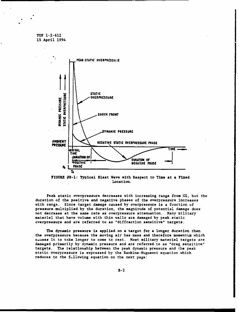
TOP 1-2-61215 April 1994
?EAK STATIC OVERPRESSU:."E
STATICOVERPRESSURE
o_ 0 SHOCK FRONT
YTAMIC PRESSURE
ANIWENT NEGATIVE STATIC OVERPRESSURE PHASEPRES9E
ARRIVAL TIME
ll TI- DURATION OFNEGATIVE PHASE
~hIPHASETo
FIGURE #B-1: Typical Blast Wave vith Respect to Time at a FixedLocation.
Peak static overpressure decreases with increasing range from GZ, but theduration of the positive and negative phases of the overpressure increaseswith range. Since target damage caused by overpressure is a function ofpressure multiplied by the duration, the magnitude of potential damage doesnot decrease at the same rate as overpressure attenuation. Many militarymateriel that have volume with thin walls are damaged by peak staticoverpressure and are referred to as "diffraction sensitive" targets.
The dynamic pressure is applied on a targot for a longer duration thanthe overpressure because the moving air has mass and therefore momentam whichcauses it to take longer to come to rest. Most military materiel targets aredamaged primarily by dynamic pressure and are referred to as "drag sensitive"targets. The relationship between the peak dynamic pressure and ?:he peakstatic overpressure is expressed by the Rankine-Huguenot equation whichreduces to the fillowing equation on the next page:
B-2

TOP 1-2-61215 April 1994
5 X p2
2 7Po +P
q - dynamic pressureP - overpressurePo - ambient pressure
See Table B-i for examp' s of the relationships between peak staticoverpressure, dynamic pressure, and wind velocity for an Ideal Shock Front.
TABLE B-I. Overpressure and Dynamic Pressure Relationships.
Peak Overpressure Peak Dynamic Pressure Maximum Wind Velocity(PSI) (PSI) (MPH)
100 123 1,415
72 74 1,168
50 41 934
30 17 669
20 8.1 502
10 2.2 294
5 0.6 163
2 0.1 70
The HOB of weapon detonation is highly significant in maximizing blastdamage. In order to inflict the greatest blast damage on a specific target,the optimum HOB is calculat.ed which will obtain the most effective Mach Stem.Near GZ, the incident and reflected ground shock fronts are separate. But, asthe iniLial blast wave compresses and heats the surrounding air, it generatesa swifter medium to which the reflected wave can propagate. Since thereflected wave travels faster because of this heated medium, it joins theinitial blast wave and forms an almost vertical and reinforced shock frontcalled the Mach Stem. The location where the incident and reflected wavesconverge is called the Triple Point. The formation of the Mach Stem producesan immediate and significant rise in exerted pressures which decreases withincreasing range from GZ.
In addition, the shock front is also reflected by the face of the target.
B-3
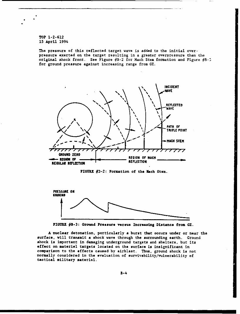
TOP 1-2-61215 April 1994
The pressure of this reflected target wave is added to the initial over-pressure exerted on the target resulting in a greater overprcessure than theoriginal shock front. See Figure #B-2 for Mach Stem formation and Figure #B-^for ground pressure against increasing range from GZ.
INCIDENTWAVE
S\ . REFLECTED% %•, "WAVE
of\
\,• ,• -.. PATH OF\ ""1.P" TRIPLE POINT
GROUND ZERO-0- is" orREGION OF NACH
REGbULAII11Rl.T REFLECTION
FIGURE #3-2: Formation of the Nach Stem.
PRESSURE ON$ROUND
FIGURE #B- 3: Grownd Pressure versus Increasing Distance from GZ.
A nuclear detonation, particularly a burst that occurs under or near thesurface, will transmit a shock wave through the surrounding earth. Groundshock is important in damaging underground targets and shelters, but itseffect on material targets located on the surface is insignificant incomparison t~o the effects caused by airblast. Thus, ground shock is notnormally considered in the evaluation of survivability/vulnerability oftactical military materiel.
B-4
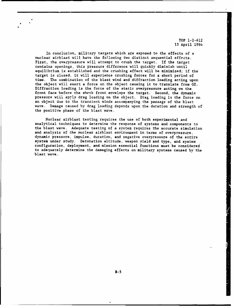
TOP 1-2-61215 April 1994
In conclusion, military targets which are exposed to the effects of anuclear airblast will have the following two distinct sequential effects.First, the overpressure will attempt to crush the target. If the targetcontains openings, this pressure difference will quickly diminish untilequilibrium is established and the crushing effect will be minimized; if thetarget is closed, it will experience crushing forces for a short period oftime. The combination of the blast wind and diffraction loading acting uponthe object will exert a force on the object causing it to translate from GZ.Diffraction loading is the force of the static overpressure acting on thefront face before the shock front envelops the target. Second, the dynamicpressure will aprly drag loading on the object. Drag loading is the force onan object due to the transient winds accompanying the passage of the blastwave. Damage caused by drag loading depends upon the duration and strength ofthe positive phase of the blast wave.
Nuclear airblast testing requires the use of both experimental andanalytical techniques to determine the response of systems and components tothe blast wave. Adequate testing of a system requires the accurate simulationand analysis of the nuclear airblast environment in terms of overpressure,dynamic pressure, impulse, duration, and negative overpressure of the entiresystem under study. Detonation altitude, weapon yield and type, and systemconfiguration, deployment, and mission essential functions must be consideredto adequately determine the damaging effects on military systems caused by theblast wave.
B-5
TOP 1-2-61215 April 1994
APPENDIX C. NUCLEAR THERMAL RADIATION ENVIRONMENT AND EFFECTS
Approximately thirty-five percent of the total energy generated by anendo-atmospheric detonation of a generic nuclear weapon is in the form ofthermal radiation. After the detonation of a thermonuclear weapon, the coreof the explosion attains an exceedingly high temperature in the tens ofmillion degrees. As a consequence of these exceedingly high temperatures, thecore radiates electromagnetic energy which peaks to the soft X-ray spectrum.The absorption of these X-rays by the surrounding air produces tremendous heatwhich creates the fireball. This generated fireball radiates electromagneticenergy from 250 nanometers in the ultraviolet to 4000 nanometers in theinfrared and produces the damaging thermal effects upon military targets.These damaging effects have two governing mechanisms, the total heat deliveredand the rate of aelivery. As weapon yield is increased, the larger thefireball becomes which significantly increases the total amount of energy thatmust be dissipated and the duration of energy dissipation. Since thisduration is significantly greater for higher yields, the delivery rate ofthermal radiation is greatly reduced; therefore, reducing the damaging effectsto a military target receiving similar thermal doses from different weaponyields.
In other words, for a specific thermal dose (total energy), a smalleryield weapon can inflict greater damage upon a specified target than a higheryield weapon because the smaller yield delivers the thermal radiation quicker.The three distinct factors which affect the damaging effects of thermalradiation are blast wave screening, inverse square law, and, absorption andscattering due to the atmosphere.
The first factor is blast wave screening. As discussed earlier, thethermal radiation is emitted in two distinct separate pulses. The first pulseis generated by the interaction of the fireball radiating maximum energy andthe departure of the shock £ront. As the fireball's radius increases, theshock front departs from the fireball heating the surrounding air toincandescence which absorbs the thermal radiation from the fireball. Thisincandescence screens the fireball and causes the shock front to emit thermalradiation instead of the fireball. This process is called blast wave
* screening. The result is a thermal pulse of little energy and significance inregards to damage effects. As the shock front expands, the cooling of the airallows the fireball to become visible and generates the second thermal pulse.Since this second pus.* contains tremendous onergy, it is militarilysignificant. Sao Figure #C-1 for an example of the thermal radiation outputof a nuclear weapon.
C-I

TOP 1-2-61215 April 1994
?a---- -- ----- "-
-m
.\/
Thu MM QPUSIO (Sacoue
FIGURE #C-1: Fireball Temperature Versus Time During I kTExplosion.
The second factor affecting thermal radiation is the inverse square laweffect. The inverse square law pertains to all forms of electromagneticradiation and states that the thermal dose varies as the total energy emittedand inversely as the square of the range from the point of burst. See Figure#C-2 for inverse square law equation and Figure #C-3 on the following page forslant ranges for specified thermal exposures.
Q (calsIcm2) . R24 R2
E - Total Energy EmittedR - Range in centimetersT - Transmissitivy of the SurroundingAtmosphere from the Burst to the Target
FIGURE #C-2: Inverse Square Law Equation.
C-2
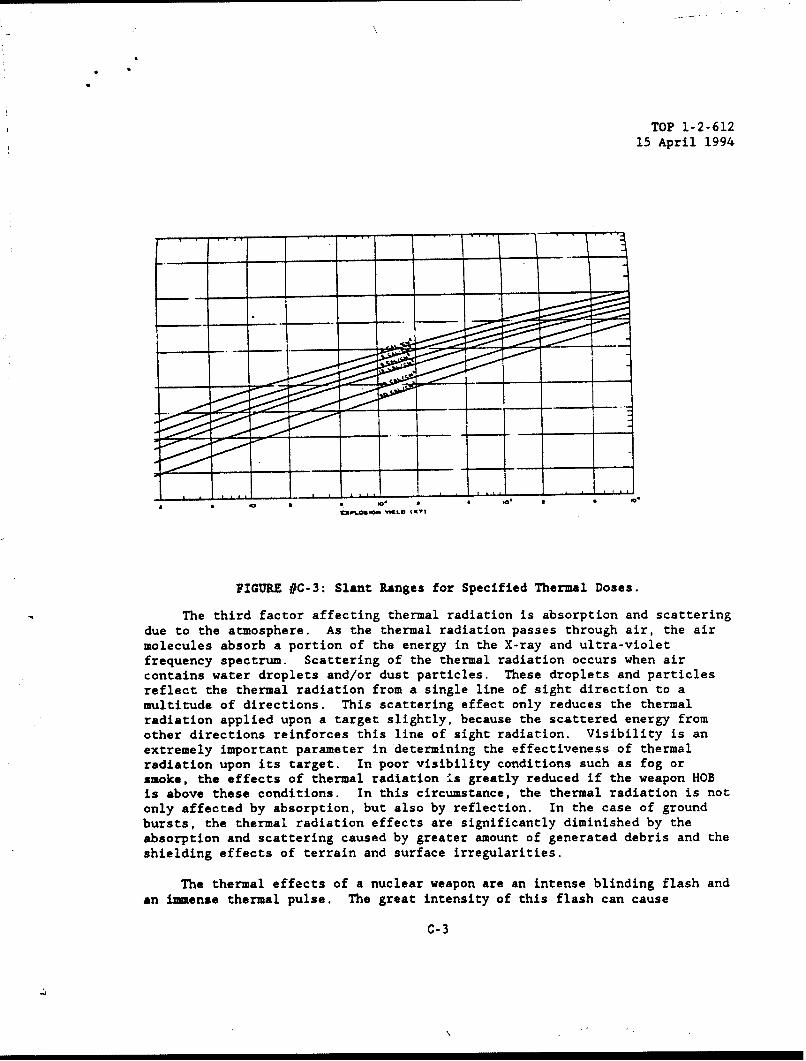
TOP 1-2-61215 April 1994
L'~.SO tL 1.1 -
FIGURE #C-3: Slant Ranges for Specified Thermal Doses.
The third factor affecting thermal radiation is absorption and scatteringdue to the atmosphere. As the thermal radiation passes through air, the airmolecules absorb a portion of the energy in the X-ray and ultra-violetfrequency spectrum. Scattering of the thermal radiation occurs when aircontains water droplets and/or dust particles. These droplets and particlesreflect the thermal radiation from a single line of sight direction to amultitude of directions. This scattering effect only reduces the thermalradiation applied upon a target slightly, because the scattered energy fromother directions reinforces this line of sight radiation. Visibility is anextremely important parameter in determining the effectiveness of thermalradiation upon its target. In poor visibility conditions such as fog orsmoke, the effects of thermal radiation is greatly reduced if the weapon HOBis above these conditions. In this circumstance, the thermal radiation is notonly affected by absorption, but also by reflection. In the case of groundbursts, the thermal radiation effects are significantly diminished by theabsorption and scattering caused by greater amount of generated debris and theshielding effects of terrain and surface irregularities.
The thermal effects of a nuclear weapon are an intense blinding flash and
an immense thermal pulse. The great intensity of this flash can cause
C-3
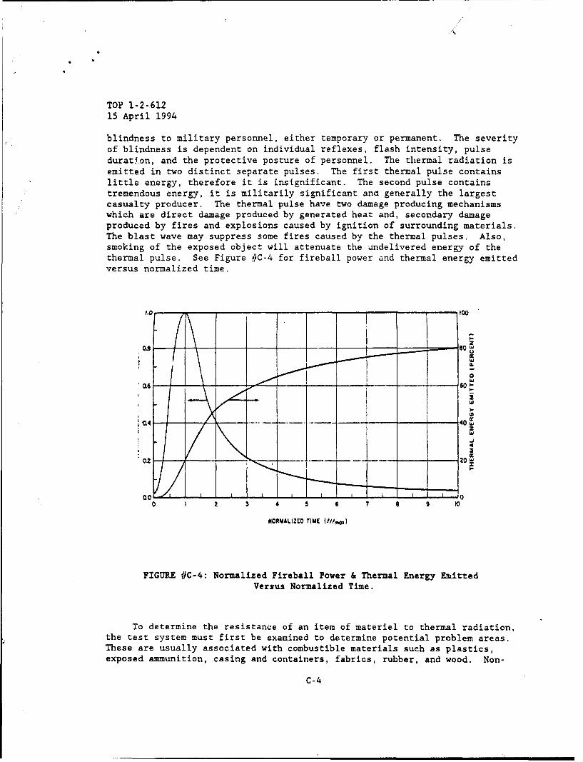
TOP 1-2-61215 April 1994
blindness to military personnel, either temporary or permanent. The severityof blindness is dependent on individual reflexes, flash intensity, pulseduration, and the protective posture of personnel. The thermal radiation isemitted in two distinct separate pulses. The first thermal pulse containslittle energy, therefore it is insignificant. The second pulse containstremendous energy, it is militarily significant and generally the largestcasualty producer. The thermal pulse have two damage producing mechanismswhich are direct damage produced by generated heat and, secondary damageproduced by fires and explosions caused by ignition of surrounding materials.The blast wave may suppress some fires caused by the thermal pulses. Also,smoking of the exposed object will attenuate the undelivered energy of thethermal pulse. See Figure #C-4 for fireball power and thermal energy emittedversus normalized time.
0 .
"OL6 "0)
, W
:1.4 ... 40 W
02 .-- 20
0.0 ,0
0 2 3 4 5 7 T 9 0
NORMALIZED TIME (//Imo,)
FIGURE #C-4: Normalized Fireball Power & Thermal Energy EmittedVersus Normalized Time.
To determine the resistance of an item of materiel to thermal radiation,the test system must first be examined to determine potential problem areas.These are usually associated with combustible materials such as plastics,exposed ammunition, casing and containers, fabrics, rubber, and wood. Non-
C-4
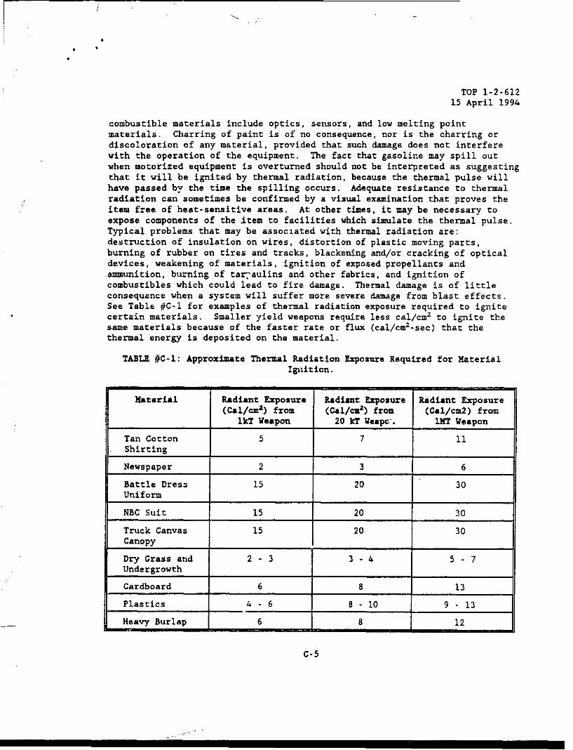
TOP 1-2-61215 April 1994
combustible materials include optics, sensors, and low melting pointmaterials. Charring of paint is of no consequence, nor is the charring ordiscoloration of any material, provided that such damage does not interferewith the operation of the equipment. The fact that gasoline may spill outwhen motorized equipment is overturned should not be interpreted as suggestingthat it will be ignited by thermal radiation, because the thermal pulse willhave passed by the time the spilling occurs. Adequate resistance to thermalradiation can sometimes be confirmed by a visual examination that proves theitem free of heat-sensitive areas. At other times, it may be necessary toexpose components of the Item to facilities which simulate the thermal pulse.Typical problems that may be associated with thermal radiation are:destruction of insulation on wires, distortion of plastic moving parts,burning of rubber on tires and tracks, blackening and/or cracking of opticaldevices, weakening of materials, ignition of exposed propellants andammunition, burning of tar'aulins and other fabrics, and ignition ofcombustibles which could lead to fire damage. Thermal damage is of littleconsequence when a system will suffer more severe damage from blast effects.See Table #C-1 for examples of thermal radiation exposure required to ignitecertain materials. Smaller yield weapons require less cal/cm2 to ignite thesame materials because of the faster rate or flux (cal/cm2-sec) that thethermal energy is deposited on the material.
TABLE #C-1: Approximate Thermal Radiation Exposure Required for MaterialIgnition.
Material Radiant Exposure Radiant Exposure Radiant Exposure(Cal/cm2 ) from (Cal/cm') from (Cal/cm2) from
lkT Weapon 20 kT Weapch, MT Weapon
Tan Cotton 5 7 11Shirting
Newspaper 2 3 6
Battle Dress 15 20 30Uniform
NBC Suit 15 20 30
Truck Canvas 15 20 30Canopy
Dry Grass and 2 - 3 3 - 4 5 - 7Undergrowth
Cardboard 6 8 13
Plastics 4 - 6 8 - 10 9 - 13
Heavy Burlap 6 8 12
C-5

TOP 1-2-61215 April 1994
APPENDIX D. ELECTROMAGNETIC ENVIRONMENT AND EFFECTS
The electromagnetic environment produced by a nuclear weapon consists ofthe ionization of the atmosphere and generation of an EMP. The gamma rays,neutrons, beta particles, X-rays, and positive ions emitted from the nucleardetonation causes electrons to be ejected from their perspective atoms, thusionizing the atmosphere in the burst vicinity. This increase in electrondensity attenuates or refracts all electromagnetic signals from a few secondsto several hours depending on weapon yield and HOB. Radio communicationsdepend on propagation of transmitted waves through the atmosphere. Dependingon the specific frequency, this propagation occurs in one of two paths, groundor sky waves. Low frequencies utilizes the ground wave path, while the highfrequency band utilizes the sky wave path which is reflected back to earth bythe ionosphere. Very High Frequency (VHF) and Ultra High Frequency (UHF)penetrate the ionosphere, therefore, any disturbance in the ionosphere doesnot affect communications in these frequency bands. See Table# D-1 forfrequency band effects caused by atmosphere ionization.
TABLE #D-I: Frequency Band Effects Caused by Atmosphere Ionization.
BAND FREQUENCY EFFECTS ON
RANGE COMMUNICATIONS
VLF 3 - 30 kHz Limited Effects
LF 30 - 300 kHz Drastic Reductionof Sky Wave Path,but No Effects onGround Wave Path
NF 300 - 3000 kHz Same as LF
HF 3 - 30 MHz ConsiderableEffects
VHF 30 - 300 MHz Limited Effects,but PropagationEnhancementPossible
UHF 300 3000 MHz Limited Effects
RADAR 3000 10000 MHz Attenuated andRefracted
D-1

TCP 1-2-61215 April 1994
A nuclear detonation distributes approximately one millionth of itsenergy in the form of an intense EMP with a frequency content of a few hertz(Hz) to several hundred megahertz (MHz). The area affected by EMP and thecharacteristics of the pulse, are a function of burst altitude and weapondesign and yield. Typical EMP intensity is in the order of tens of thousandsof volts/meter. This compares with the order of 200 volts/meter for nearbyradars, 10 volts/meter for communication equipment, and 0.01 volts/meter fortypical metropolitan area ambient. Two characteristics of EMP which result ina threat to electrical equipment are field amplitude and broad frequencyspectrum. There are three basic mechanisms for EM coupling to a conductingstructure: electrical induction, the basic mechanism for linear conductors;magnetic induction, the principal mechanism when the conducting structureforms a closed loop; and earth transfer impedance for buried conductors.Devices which may be susceptible to functional damage due to electricaltransients include active electronic devices, passive electronic components,semiconductor devices, squibs and pyrotechnic devices, meters, and powercables. Operational upset can be expected in digital processing systems,memory units, guidance systems, and power distribution systems. Damagemechanisms include dielectric breakdown, thermal effects and interconnectionfailures. The two EMP situations which are based upon burst altitude are(Endo-Atmospheric) SREMP and (Exo-Atmospheric) HEMP.
The first EMP situation, SREMP, occurs within the atmosphere at analtitude of less than 40 km above sea level, and possesses an extremely largeelectric and magnetic field over the burst vicinity. Of particular concern isevents at or within 1 km of the surface. Only within these limits aretactical surface systems close enough to the event to have the potential to beadversely affected by SREFP. SREMP is generated by collisions between photonsfrom gamma radiation and molecules of the atmosphere. These highly energeticphotons eject electrons from the surrounding air molecules, producing ionizedair molecules. This immense separation of charge creates an intense E-Fieldof several 100,000 volts/meter and a large associated H-Field of 500 ampere-turns/meter. Ninety percent of its energy is contained in the 100 Hz to 10kHz range. See Figure# D-1 for an example of the SREMP waveform and Figure#D-2 for relative energy versus frequency for an Endo-Atmospheric Burst on thefollowing page.
D-2

TOP 1-2-61215 April 1994
-- 100's kVm-1
ELECTRICFIELD kVm-'
I O'1Os kVm'1
------- TIM
I II II II I I I
I I Il ] I =TIME
S0.1ps , 100's ps ntl tMs
FIGURE #D-1: Endo-Atmospheric EMP Waveform..
100
ENDO
w
LUJ
>_- > -"
010 10
FREQUENCY. HERTZ
FIGURE #D-2: Endo-Atmospheric Relative Energy VersusFrequency.
D-3
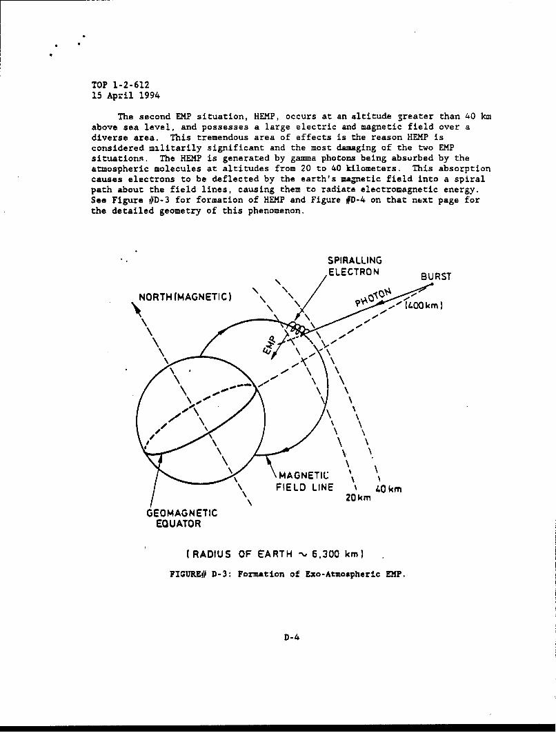
TOP 1-2-61215 April 1994
The second EMP situation, HEMP, occurs at an altitude 3reater than 40 kmabove sea level, and possesses a large electric and magnetic field over adiverse area. This tremendous area of effects is the reason HEMP isconsidered militarily significant and the most damaging of the two EMPsituations. The HEMP is generated by gamma photons being absurbed by theatmospheric molecules at altitudes from 20 to 40 kilometers. This absorptioncauses electrons to be deflected by the earth's manetic field into a spiralpath about the field lines, causing them to radiate electromagnetic energy.See Figure #D-3 for formation of HEMP and Figure #D-4 on that next page forthe detailed geometry of this phenomenon.
SPIRALLINGELECTRON BURST
NORTH(MAGNETIC)
(RADIUS~~0 OFERToo .00kn
10D-0
\ \
MAGETI
FIL LIE40k
' 0k
GEOMANETIEQUATORRAIU OF EAT\, .0 m
FIGURM~~ ~ ~ D-:Fraino\xoAmshrcEP
" \ \-4
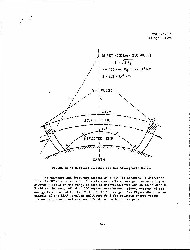
TOP 1-2-61215 April 1994
I BURST (400 km'• 250 MILES)/ ~S RE 2,'-•hh
/ I = 400 kmn. RE =6.4x10³ km// = S:2.3 x10 3 km/
/ I/ I•/ Y-I PULSE
/ ry
s/ /-- I 4k
SOURCE REGIONN
".. - REFLECTED EMP /
EARTH
FIGURE #D-4: Detailed Geometry for Exo-Atmospheric Burst.
The wavyform and frequency content of a HEMP is drastically differentfrom its SREMP counterpart. This electron radiated energy creates a large,diverse E-Field in the range of tens of kilovolts/meter and an associated H-Field in the range of 10 to 100 ampere-turns/meter. Ninety percent of itsenergy is contained in the 100 kHz to 10 MHz range. See Figure #D-5 for anexample of the HEMP waveform and Figure #D-6 for relative energy versusfrequency for an Exo-Atmospheric Burst on the following page.
D-5

TOP 1-2-61215 April 1994
- Ž 10's kVm1
ELECTRIC IFIELD kVn'"
FIGURE #D-5: Exo-Atmospheric ElP Waveform.
too
EXO
I
I
J
I
10I
0110 108
FREQUENCY. HERTZ
FIGURE #D-6: Exo-Atuospheric Relative Energy VersusFrequency.
D-6
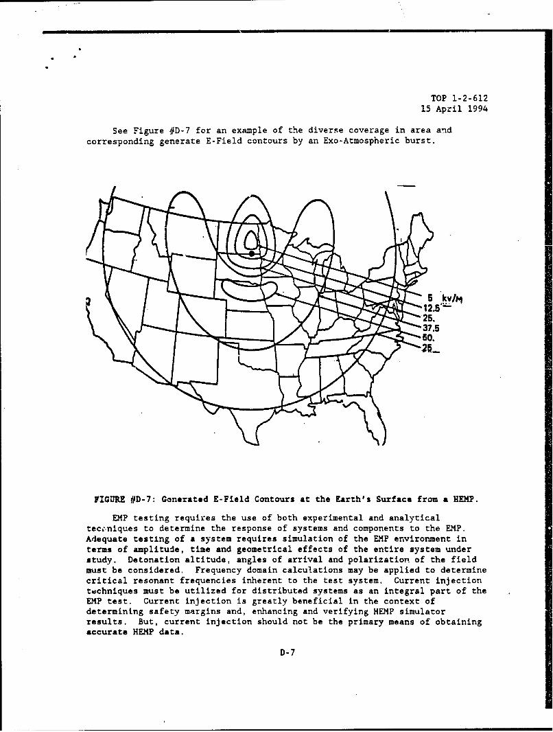
TOP 1-2-61215 April 1994
See Figure #D-7 for an example of the diverse coverage in area andcorresponding generate E-Field contours by an Exo-Atmospheric burst.
S"•12.5'
•25.S37.5
• • •60.
FIGURE #D-7: Ganerated E-Field Contours at the Earth's Surface from a HEMP.
EMP testing requires the use of both experimental and analyticalteceniques to determine the response of systems and components to the EMP.Adequate testing of a system requires simulation of the EMP environment interms of amplitude, time and geometrical effects of the entire system understudy. Detonation altitude, angles of arrival and polarization of the fieldmust be considered. Frequency domain calculations may be applied to determinecritical resonant frequencies inherent to the test system. Current injectiontdchniques must be utilized for distributed systems as an integral part of theEMP test. Current injection is greatly beneficial in the context ofdetermining safety margins and, enhancing and verifying HEMP simulatorresults. But, current injection should not be the primary means of obtainingaccurate HEMP data.
D-7
TOP 1-2-61215 April 1994
Also, deliberate hardening devices like terminal protection devices mustbe analyzed, tested if necessary, to determine safety margins. Likewise, th3attenuation afforded by enclosures must be analyzed so that its effects on thesurvivability of the enclosed electronics can be quantified.
D-8
TOP 1-2-61215 April 1994
APPENDIX E. NUCLEAR RADIATION EFFECTS
E.1 GENERAL RADIATION C11ARACTERISTICS.
Approximately fifteen percent of the energy delivered by the detonationof a nuclear weapon is produced as (non-thermal) radiation. There are fourtypes of radiation which are worthy of attention.
The first type of radiation is called alpha radiation and is comprised ofa stream of alpha particles which are essentially the nuclei of helium atoms.This type of radiation has exceeding slight penetrp.ting power causingessentially no effects on material or on military personnel because it can bestopped by a single sheet of paper. Military casualties are only produced byalpha radiation when it is internally introduced into the body. Therefore,alpha radiation is not considered militarily significant to equipment.
The second type? of radiation is called beta radiation and is comprised ofa stream of beta particles which are electrons. This type of radiation hasslight penetrating power and can just barely penetrate the skin. The onlyeffect caused by initial beta radiation on military personnel are skin burnscalled "Beta Burns." Since there are essentially no notable effects onmaterial or on military personnel, initial beta radiation has little militarysignificance.
The third type of radiation is called gamma radiation which is comprisedof photons or electromagnetic waves very similar to X-rays, but have shorterwavelengths, usually more energetic and, therefore, has substantially greaterpenetrating power. Since gamma radiation can travel great distances throughair and pass through extremely thick materials, gamma radiation is extremelysignificant to military systems containing electronics.
The last type of radiation is called neutron radiation and is comprisedof a particle stream of neutrons. Neutrons are one of the elementaryparticles which comprise the nucleus of all atoms and possess no charge.Since neutrons usually have much greater penetrating power than gammaradiation, neutrons are extremely significant to military systems containingelectronics.
E.2 RESIDUAL RADIATION ENVIRONMENT AND EFFECTS.
The residual radiation effects of a nuclear weapon consists ofradioactive weapon debris and fallout, and NIA which sustains for longer thanone minute after weapon detonation. The effects of residual a:tivity cancover an extensive area and can persist for long durations which are dependentupon weapon yield and design, HOB, soil composition, and atmosphericconditions. The radiation composition of residual radiation consists of alphaparticles, beta particles, and gamma radiation. A more detailed examinationof the two primary residual radiation effects, NIA and fallout follow:
E-1
TOP 1-2-61215 April 1994
The first effect, NIA occurs in the vicinir 3f GZ and is caused byneutron capture in the system and various materials which exist on the earth'ssurface near GZ. This process of neutron capture produces radioactiveisotopes that emit beta and/or gamma radiation. The duration of significantra-tation emissiot. is dependent upon the isotopes created.
The normally predominant effect, fallout, is highly dependent upon thetype of weapon burst. In air bursts, the vaporized radioactive productscondense into small particles in the range of 20 pm in diameter. Theseextremely small particles are conveyed high in the atmosphere and descend toearth over an exceedingly prolonged time. By this process, the fallout hassignificantly decayed and has been greatly dispersed by winds resulting in avery low radioactivity level which is militarily insignificant.
On the other hand, during ground or near ground bursts, vast quantitiesof soil and debris are drawn into the fireball forming condensation centersfor vaporized radioactive produces. This results in a massive cloud ofradioactive particles with ".'-owters up to 500 m. The rate at which theseparticles descend to earth 7 based upon increasing mass and atmosphericconditions. In other words, tW' denser the particle, the quicker it will fallto earth unless adverse atm,,pheric conditions prevail. The outcome of thistype of burst is steadily increasing radioactivity the closer to GZ themeasurement point because of the decrease in decay time and the increase inradioactive particles.
Residual radiation has essentially no damaging effects on militarysystems, but presents major difficulties on military personnel in the areasurrounding GZ and downwind of GZ. Gamma radiation is the primary concernwhen providing protection for military personnel against residual radiation.The effects of both alpha and beta radiations may be made insignificant formilitary concerns by thin layers of materials. Combat vehicles, particularlytanks and armored personnel carriers, because of their armor and massive metalconstruction, inherently provide a corsiderable amount of shielding againstresidual radiation.
The amount of shielding provided is almost a direct function of the massot material between the individual and the radiction source. The effective-ness of matericl in attenuating radiation may be represented by its "half-value thickness", the thickness of the particular material which absorbs halfof the gamma radiation incident upon it. The amount of shielding provided foreach crew member is expressed in terms of *protection factor" defined asfollows:
Free Field Radialtion level at 3 feet above the groundProtection Factor -..-----
Radiaticn level at personnel location
E-2

TOP 1-2-61215 April 1994
The protection factor is the ratio of the radiation dose a person wouldrece: if he were standing in the open in a fallout field to the dose hewould receive in the vehicle at the same location. Some tanks may provideprotecton factors against residual radiation as high as 20, whereas a 1/4-tontruci may provide a protection factor of 1.25. The term "transmission factor"is also used. It is essentially the inverse of the protection factor and isAefinek. as:
Dose inside ShieldTransmission Factor -
Dose outside Shield
Typical transmission factors for shelters and vehicles against initial andresidual radiation are contained in Table #E-1.
TABLE #E-1: Typical Transmission Factors for Nuclear Radiation Effects.
Shielding Item Residual Neutrons CaOaARadiation Initial Radiation InitialTransmission Transmission RadiationFactor Factor Transmission
Factor
Armored 0.6 0.7 0.7PersonnelCarrier
Light Tank 0.2 0.3 0.2
Medium Tank 0.1 0.3 0.1
W-Ton Truck 0.8 1.0 1.0
X-Ton Truck 0.7 1.0 i.0
2%-Ton Truck 0.6 1.0 1.0
4- To 7-Ton 0.5 1.0 1.0Truck
Foxhole 0.1 0.3 0.2
Open Trench 0.1 0.3 0.2
Shelter with 3ft 0.005 0.05 0.02of Earth Cover
E-3

TOP 1-2-612
15 April 1994
E.3 INITIAL NUCLEAR RADIATION ENVIRONMENT AND EFFECTS.
Initial nuclear radiation is defined as that nuclear radiation which isemitted by a nuclear explosion within the first minute after the nuclearweapon burst. Initial nuclear radiation is composed of alpha particles, betaparticles, gamma radiation and neutrons. Only, the highly penetrative gammarays and neutrons are extremely damaging to military personnel and electronicsin military systems. The magnitude of this radiation is dependent upon weaponyield, type and HOB, and distance from GZ. For middle to high yield weapons,the damaging effects on systems generated by the blast wave and thermalradiation surpasses INR effects. However, for tanks, APCs, and similarsystems, and for small yield weapons, INR is the more dominant effect onelectronics and personnel.
The gamma radiation that is produced by a nuclear detonation comes fromvarious sources, such as the initial fission reaction, fission product decayand NIA in the warhead debris and in the surrounding air molecules. Promptgamma photons are those produced during fission and as a result of neutroninteractions with weapon materials in the first jusec. Capture gamma photonsare those emitted as the result of the capture of a neutron by a nucleus.Other examples of gamma radiation sources are delayed and in elastic gammaphotons.
The neutron radiation produced by a nuclear detonation comeb from twomain sources, prompt neutrons and delayed neutrons. Prompt neutronsconstitute over 99 percent of the total neutron production and are released inthe initial isec during the warhead fission and/or fusion processes. Delayedneutrons are emitted within the first minute and are produced by theinteraction of the prompt neutrons with atoms in their path. Neutrons arealso produce by the action of high energy gamma photons on the weaponmaterials, but they are insignificant.
As the distance from GZ increases, the effects of INR is significantlyreduced by two factors. These factors are that the intensity of INR decreasesaccording to the inverse square law, and air scattering and absorption. Theinverse square law is the principle factor for decreases in INR levels. Thefactor of air scattering and absorption has very little effect on neutrondose, but affects gamma radiation dose significantly. Figure #E-1 is anexample of initial radiation effects from a lkT airburst and Figure #E-2provides INR scaling factors versus weapon yield.
E-4
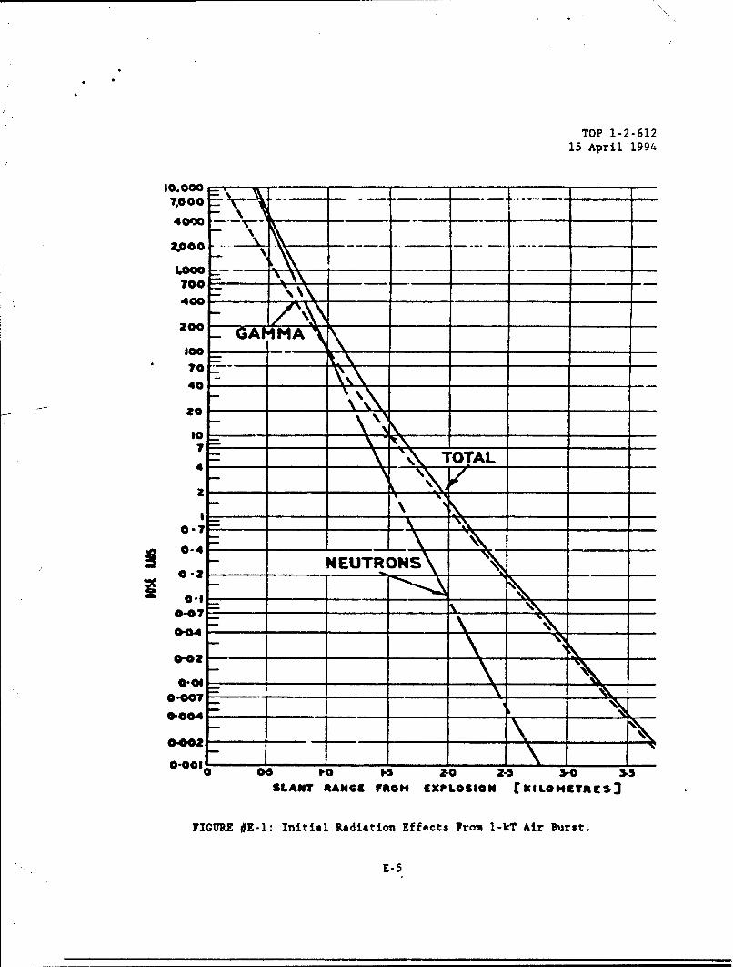
TOP 1-2-61215 April 1994
10.0007,000 --
40M00
7o.oo--...- __
700 - -_\_\\400
G Moo A100-
• 70_-
40
80 ____
4 TOT,0AL
0-4-
z-1 R -0.40-02
0-04
0-0070-004
0-002
0-001
0"00I0 06 20 1- 2-0 2-S -0 3-5
SLANT RANGE FROM EXPLOSION EKILOMEITRES
FIGURE #E-l: Initial Radiation Effects From 1-kT Air Burst.
"E-5

TOP 1-2-61215 April 1994
74
2"o
5 0 - - - -. - - - -,
7 -00 - - - - -
7 -
4 40 710 10 n 4O 0O0 oI 2OLT KT ,NIT
MXPLOSION YIELD
FIGURE #E-2: IRl Scaling Factors Versus Weapon Yield.
E-6
TOP 1-2-61215 April 1994
The INR shielding tests involve the exposure of materiel to neutron andgamma radiation sources to measure the protection afforded to the crew and themost vulnerable electronic components by the walls of the v~hicle. Theseradiation sources must have spectra that collectively approximate the spectrafrom nucl-2ar weapons. See Table #E-1 on page 48 for typical transmissionfactors of INR effects on military equipments and shelters.
The INR tests are only concerned with the effects on military personnelmuid equipment from gamma radiation and neutrons. The damaging effectsproduced by INR are only militarily significant in the consideration of thedrastic effects it induces on electrical properties of semiconductor devices.To adequately test and analyze these drastic effects, three test environmentsbased upon the time history of nuclear weapon radiation effects have beendeveloped. These tests are: gamma dose rate, total gamma dose, and neutronfluence.
The gamma dose rate test determines the effects of the initial gammapulse created by a nuclear detonation on powered semiconductor devicesprimarily of the Metal-Oxide-Semiconductor (MOS) technology. The gamma doserate pulse generates damaging photocurrents which produces transient upsets,latchup, and burnout in semiconductor devices.
The neutron fluence test determines the effects of lattice displacementdamage generated by neutron fluence on semiconductor devices primarily of thebipolar technology. The semiconductor piece-parts of a test system generallyreceives the most damage by neutrons. Neutron damage results in a decrease ofthe minority carrier lifetime and an increase in bulk resistivity of thesemiconductor material. These effects severely alters the electricalcharacteristics of the piece-parts, and, in some cases, the induced damage issevere enough to cause complete device failure or failure in its circuitapplication.
The total gamma dose test determines the effect of total ionizing dosedeposited on semiconductor devices. The production of hole-electron pairsthrough ionization creates trapped charge in the semiconductor material. Thetotal dose effects in semiconductors are exhibited either as a change inelectrical parameters or as a catastrophic failure. Of particular concern isN-channcl MOS technology which is the sensitive to gamma dose.
See Table #E-2 for the testing requirements on specific semiconductortechnologies at tactical damage levels and Table #E-3 for testing requirementson generic part families.
E-7
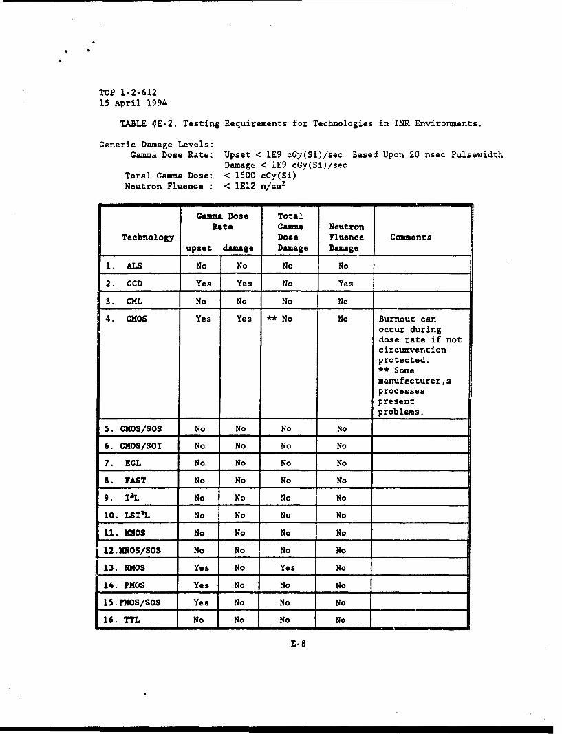
TOP 1-2-61215 April 1994
TABLE #E-2: Testing Requirements for Technologies in INR Environments.
Generic Damage Levels:Gamma Dose Rate: Upset < lE9 cGy(Si)/sec Based Upon 20 nsec Pulsewidth
Damagc < 1E9 cGy(Si)/secTotal Gamma Dose: < 1500 cGy(Si)Neutron Fluence : < 1E12 n/cm2
Gamma Dose TotalRate Gamma Neutron
Technology Dose Fluence Comments______ upset damage Damage Damage
1. ALS No No No No
2. CCD Yes Yes No Yes
3. CML No No No No
4. CMOS Yes Yes ** No No Burnout canoccur duringdose rate if not
circumventionprotected.** Somemanufacturer,sprocessespresentproblems.
5. CMOS/SOS No No No No
6. CMOs/Sol No No No No
7. ECL No No No No
S. FAST No No No No
9. I2L No No No No
10. LSTIL No No No No
11. MIOS No No No No
12.MOS/SOS No No No No
13. NMOS Yes No Yes No
14. FMOS Yes No No No
15.PMOS/SOS Yes No No No
16. TTL No No No No
E-8
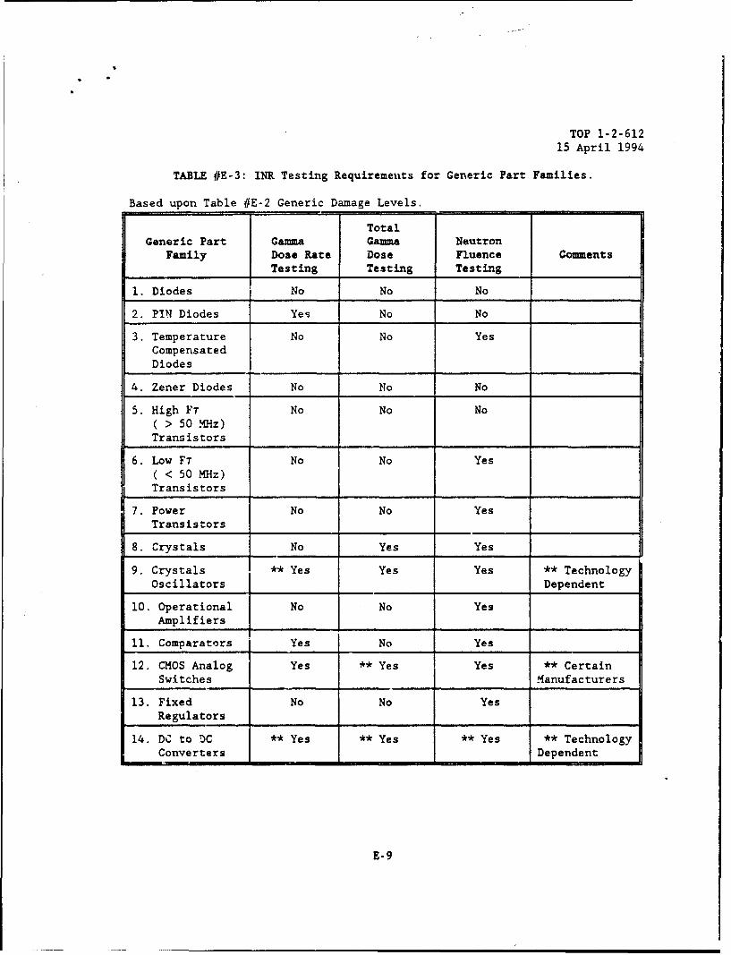
TOP 1-2-61215 April 1994
TABLE #E-3: INR Testing Requirements for Generic Part Families.
Based upon Table #E-2 Generic Damage Levels.
TotalGeneric Part Gamma Gamma Neutron
Family Dose Rate Dose Fluence CommentsTesting Testing Testing
1. Diodes No No No
2. PIN Diodes Yes No No
3. Temperature No No YesCompensatedDiodes
4. Zener Diodes No No No
5. High Fr No No No( > 50 -MHz)Transistors
6. Low FT No No Yes( < 50 MHz)Transistors
7. Power No No Yes
Transistors
8. Crystals No Yes Yes
9. Crystals ** Yes Yes Yes ** TechnologyOscillators Dependent
10. Operational No No YesAmplifiers
11. Comparators Yes No Yes
12. CMOS Analog Yes ** Yes Yes ** CertainSwitches Manufacturers
13. Fixed No No YesRegulators
1.4. DC to DC ** Yes ** Yes ** Yes ** TechnologyConverters Dependent
E-9
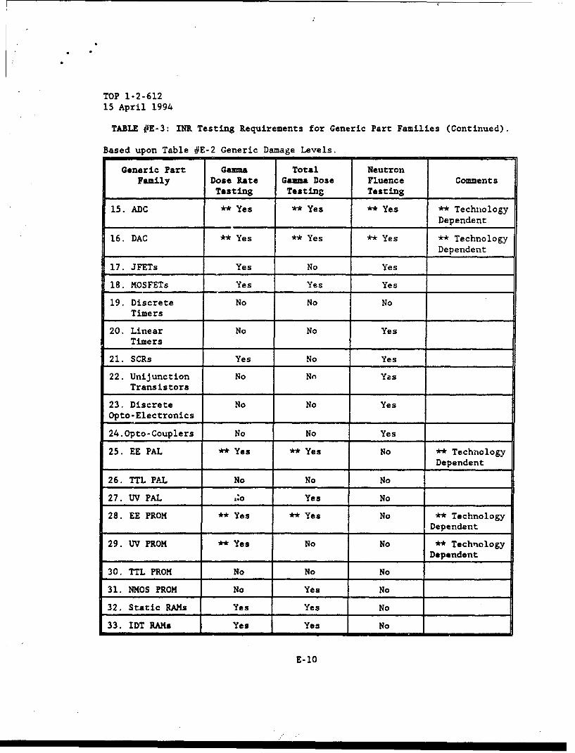
TOP 1-2-612
15 April 1994
TABLE #E-3: INR Testing Requirements for Generic Part Families (Continued).
Based upon Table #E-2 Generic Damage Levels.
Generic Part Ga&aa Total NeutronFamily Dose Rate Gamma Dose Fluence Comments
Testing Testing Testing
15. ADC ** Yes ** Yes ** Yes ** TechnologyDependent
16. DAC ** Yes ** Yes ** Yes ** TechnologyDependent
17. JFETs Yes No Yes
18. MOSFETs Yes Yes Yes
19. Discrete No No NoTimers
20. Linear No No YesTimers
21. SCRs Yes No Yes
22. Unijunction No No YasTransistors
23. Discrete No No YesOpto-Electronics
24.Opto-Couplers No No Yes
25. EE PAL ** Yes ** Yes No ** TechnologyDependent
26. TTL PAL No No No
27. UV PAL ,.o Yes No
28. EE PROM ** Yes **Yes No ** TechnologyDependent
29. UV PROM ** Yes No No ** TechnologyDependent
30. TTL PROM No No No
31. NMOS PROM No Yes No
32. Static RAMs Yes Yes No
33. IDT RAMs Yes Yes No
E-10
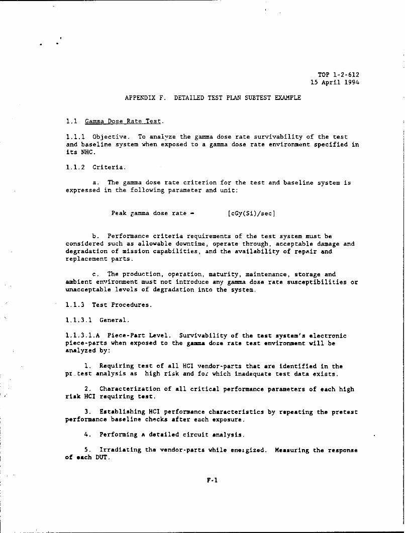
TOP 1-2-61215 April 1994
APPENDIX F. DETAILED TEST PlAN SUBTEST EXAMPLE
1.1 Gamma Dose Rate Test.
1.1.1 Objective. To analyze the gamma dose rate survivability of the testand baseline system when exposed to a gamma dose rate environment specified inits NHC.
1.1.2 Criteria.
a. The gamma dose rate criterion for the test and baseline system isexpressed in the following parameter and unit:
Peak gamma dose rate - [cGy(Si)/sec]
b. Performance criteria requirements of the test system must beconsidered such as allowable downtime, operate through, acceptable damage anddegradation of mission capabilities, and the availability of repair andreplacement parts.
c. The production, operation, maturity, maintenance, storage andambient environment must not introduce any gamma dose rate susceptibilities orunacceptable levels of degradation into the system.
1.1.3 Test Procedures.
1.1.3.1 General.
1.1.3.1.A Piece-Part Level. Survivability of the test system's electronicpiece-parts when exposed to the gamma dose rate test environment will beanalyzed by:
1. Requiring test of all HCI vendor-parts that are identified in thepr test analysis as high risk and for which inadequate test data exists.
2. Characterization of all critical performance parameters of each highrisk HCI requiring test.
3. Establishing HCI performance characteristics by repeating the pretestperformance baseline checks after each exposure.
4. Performing a detailed circuit analysis.
5. Irradiating the vendor-parts while eneigized. Measuring the responseof each DUT.
F-i

TOP 1-2-61215 April 1994
6. Establishing design margins (99/90) utilizing the results of thecircuit analysis and the characterization/test program conducted at 1X, 5X,and 1OX, unless consistent piece-part failures dictates other reasonabledesign margins.
7. Accepting/rejecting high risk HCIs based on Design Margins (DM) whichare defined as:
DM - Effects Threshold LevelCriteria Dose Rate Level
1.1.3.1.3 System Level. Survivability of the test system to the gamma doserate test environment will be analyzed by:
1. Performing a detailed pretest analysis.
2. Utilizing DMs on all HCIs.
3. Analyzing deliberate hardening devices and/or techniques foradequacy.
4. Establishing performance and configuration baseline of the testsystem prior to testing.
5. Irradiating the system while energized ard operating.
6. Establishing the system' operational status by identifying andquantifying performance differences after each gamma dose rate exposure byrepeating the baseline and diagnostic checks as necessary.
7. Irradiating the test system in different configurations,oriencations, and modes.
8. Documenting all upsets and/or damage, downtime, mission performanceimpacts, and necessary corrective action procedures.
9. Stressing the system by utilizing multiple exposures at each level.
10. Exposing mission critical items to levels that can be utilized toverify a specified DM of at least 2X with 4X as the target.
11. Determining and quantifying differences between critical parametersof the test and USANCA environments.
12. Determining survivability of the test i:em/system to the testenvironment.
F-2

TOP 1-2-61215 April 1994
13. Establishing the system's baseline configuration.
14. Determining all serious effects on mission performance.
If a problem occurs, the power will be recycled in an attempt to returnthe unit to an operational status.
1.1.3.1.C Baseline Configuration. The survivability of the baseline systemconfiguration when exposed to the gamma dose rate USANCA environment will beanalyzed by:
1. Analyzing the differences between the test and USANCA environments.
2. Analyzing the differences between the test and baselineconfigurations.
3. Determining the response of the baseline configuration to the USANCAenvironment.
1.1.3.2 Approved Test Facilities. Approved Department of Defense (DOD) orother gamma dose rate facilities which are available for gamma dose ratetesting are listed in Defense Nuclear Agency (DNA) publication, DASIAC SR-90-252, "Guide to Nuclear Weapons Effects 'Simulation Facilities andTechniques"(1990 Edition) on pages 5-63 through 5-128 and approved DODfacilities since the publication of that DNA publication. Facilities such asthe WSMR LINAC should be utilized for piece-parts, WSMR REBA for smallsystems, and HERMES III for large systems. The PE must ensure trut the gammadose rate test facility utilized is the foremost facility to act. telysimulate desired criteria that will maximize effects on the test systemconfiguration.
1.1.3.3 Pretest Analysis. During the pretest analysis, the PE must analyzeand identify HCIs and high risk areas of the test system to the gamma doserate environment. To do this the PE must effectively perform the followingtasks:
a. Identify all potentially suscep'.ible electronic piece-parts basedupon technology.
b. Identify the most realistic and severe test setup/circuit withrespect to the radiation exposure.
c. Identify all circumvention and/or gamma dose rate hardeningapplications.
d. Identify the type, number, and location of all dosimetry and dataacquisition.
e. Establish the baseline configuration of the test system.
F-3
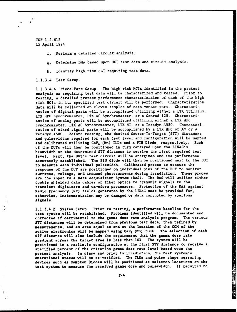
TOP 1-2-612
15 April 1994
f. Perform a detailed circuit analysis.
g. Determine DMs based upon HCI test data and circuit analysis.
h. Identify high risk HCI requiring test data.
1.1.3.4 Test Setup.
1.1.3.4.A Piece-Part Setup. The high risk HCIs identified in the pretestanalysis as requiring test data will be characterized and tested. Prior totesting, a detailed pretest performance characterization of each of the highrisk HCIs in its specified test circuit will be performed. Characterizationdata will be collected on eleven samples of each vendor-part. Characteri-zation of digital parts will be accomplished utilizing either a LTX Trillium,LTX HPC Synchromaster, LTX AC Synchromaster, or a Genrad 125. Characteri-zation of analog parts will be accomplished utilizing either a LTX HPCSynchromaster, LTX AC Synchromaster, LTX HT, or a Teradyn A580. Characteri-zation of mixed signal parts will be accomplished by a LTX HPC or AC or aTeradyn A580. Before testing, the desired Source-To-Target (STT) distancesand pulsewidths required for each test level and configuration will be mappedand calibrated utilizing CaF 2 (Mn) TLDs and a PIN Diode. respectively. Eachof the DUTs will then be positioned in turn centered upon the LINAC'sbeamwidth at the determined STT distance to receive the first required testlevel. Next, the DUT's test circuit will be energized and its performanceaccurately established. The PIN diode will then be positioned next to the DUTto measure each individual pulsewidth. Calibrated probes to measure theresponse of the DUT are positioned on individual pins of the DUT to monitorcurrents, voltage, and induced photocurrents during irradiation. These probesare the input to a Data Acquisition System (DAS). The DAS will utilize eitherdouble shielded data cables or fiber optics to transmit signals to thetransient digitizers and waveform processors. Protection of the DAS againstRadio Frequency (RF) fields generated by the LINAC must be provided for,otherwise, instrumentation may be damaged or data corrupted by spurioussignals.
1.1.3.4.B System Setup. Prior to testing, a performance baseline for thetest system will be established. Problems identified will be documented andcorrected if detrimental to the gamma dose rate analysis program. The variousSTT distances will be determined from previous test data, then refined by"measurements, and an area equal to and at the location of the COM of theactive electronics will be mapped using CaFa (Mn) rLDs. The selection of eachSTT distance will also include the requirement that the gamma dose rategradient across the target area is less than 10%. The system will bepositioned in a realistic configuration at the first STT distance to receive aspecified percent of the criterion gama dose rate level based upon thepretest analysis In place and prior to irradiation, the test system'soperational status will be re-verified. The TLDs and pulse shape measuringdevices such as Compton Diodes will be positioned at 3elacted locations on thetest system to measure the received gamm dose and pulsewidth. If required to
F-4

TOP 1-2-61215 April 1994
adequately determine the gamma dose rate response of the test system, a DASwill be setup and calibrated. The DAS will consist of various sensors, doubleshielded data cables or fiber optics, transient digitizers, and waveform.processors. Protection of the DAS against RF fields must be provided for,otherwise, instrumentation may be damaged or data corrupted by spurioussignals. The test system will be powered during each irradiation.
1.1.3.5 Test.
1.1.3.5.A Piece-Part Level. Ten samples of each vendor-part will becharacterized, irradiated at IX the criterion level while biased, andcharacterized again. This procedure will be repeated at 2X, 5X, and 1OX thecri.terion level unless a valid failure occurs such as the vendor-part failingto meet manufacturer's specifications, upset, latch-up or burnout. Aneleventh sample will be characterized and kept as a control device. If avalid failure occurs, at or below the criterion level, the vendor-part failsqualification. If a valid failure occurs above the criterion level, then thisinformation along with the circuit analysis will be utilized to establish theDM which, in turn, will be utilized to determine acceptance/rejection of thepart. After the DUTs has been irradiated by gamma dose rate pulses, allcircuit operational checks will be initiated within 3 minutes after theirradiation IAW MIL-STD-883 (REF 30), Methods 1020, 1021, and 1023; and MIL-STD-750 (REF 21), Method 1015. The majcr parameters of the test environmentwill be analyzed against the USANCA environment and a criteria compliance willbe obtained. This criteria compliance must be utilized in determining thesurvivability of the vendor-part against the USANCA criteria.
1.1.3.5.B System Level. After the energized system has been irradiated at IXthe criterion level by a pulse of bremsstrahluxig photons, all operationalchecks will be initiated within 3 minute aftar the irradiation. If determinedto be operational within acceptable guidelines, the test system's dosimetrywill be replaced and the test system will be pulsed again. Following asuccesiful checkout, the dosimetry will be replaced will unexposed ones, thesystam repositioned and irradiated again. All necessary performance baselinechecks between gamma dose rate pulses should be thorough, but as abbreviatedas possible to achieve an efficient test program. This process will berepeated until all configurations, modes, orientations and levels identifiedby the pretest analysis or on-going test results have been accurately tested,analyzed, and documented. Testing at IX, 2X, 3X, and 5X the criterion levelwill be accomplished unless unacceptable problems occur. If an upset orlatchup occurs, the problem will documented and diagnosed. Testing will riotbe continued until the problem is completely understood and its effects on thesystem has been deteruined. The effected subsystem(s; will be identified and,depending on the PE's analysis, testing may be repeated to ensure that theproblem was environment induced. Test/diagnostic circuits will be employed tocollect information requir~d to decermine the cause and impacts on thesystem's mission. Work arounds, as necessary, will be implemented to completethe testing. A follow-up investigation will be performed to identify thefailure to the vendor-part level. A final operational baseline check will be
F-5

TOP 1-2-61215 April 1994
perfermed on tne test system at the end of the test. If possible, additionaltest systems will be tested, analyzed, and documented as specified above toachieve extremely important statistical confidence in the gamma dose ratesurvivability of the test system. The test environment will be analyzedagainst the USANCA environment and a criteria compliance obtained. Thiscriteria compliance must be utilized in determining the survivability of thetest configuration against the USANCA criteria.
1.1.3.6 Dosimetry. The gamma dose at selected locations on the test systemwill be measured using CaF 2 (Mn) TLDs. The measured gamma dose values will bein cGy(CaF2(Mn)) and must be converted and expressed in cGy(Si) andcGy(tissue) by the ratios:
cGy(Si)/cGy(CaF2 ) - 1.02 and cGy(tlssue)/cGy(CaF2 ) - 1.13, respectively.
Eacf- radiation pulse will. be measured using a PIN diode (LINAC) or ComptonDiode (HERMES-III and RE.BA), and digitized on a transient digitizing system.The pulsewidth (FWHM) of each radiation pulse will be obtained from thisdigitized signal. The gamma dose rate for each ptilse will then be determ4 nedfrom the gamma dose recorded on the TLDs and the pulsewidth obtained from thedigitizers.
1.1.4 Data Required.
a. Detailed description of the method and facility of producing thegamma dose rate test environment including photographs rf the test facilitysetup showing test system location relative to the gamma radiation source.
b. Complete set of pretest mapping data in radiation absorbed dose(cGy) in silicon (cGy(Si))(±lO%) and cGy(t1ssue) (±10%) for each expected testlocation.
c. Risetime and pulsewidth (FWHM) of each gamma pulse.
d. Date from other ga&&a dose rate test/analysis programs performed onsimilar military systems.
e. Results of pretest analysis.
f. Test data and/or analytical data and analysis on the test systemfrom contractor such as design parameter reports.
g. List of all active electronic piece-parts utilized in the testsystem.
h. Available test data for all HCIs from existing databases.
i. Detailed description, serial nurbers, and dimensions of each
F-6
TOP 1-2-61215 April 1994
subsystem of the test system.
J. Detailed description and electrical schematics of test circuitsutilized.
k. Results of all circuit analysis to include design margins.
1. Detailed description of all mission essential functions.
m. Copies of documentation such as the nuclear program plan, nucleartest plan, nuclear test report, hardness assurance plan, maintenance/surveillance assurance plan.
n. Duration of each gamma radiation pulse (sec) (±5%).
o. Total gamma dose expressed in cGy(Si) and cGy(tissue) (±10%).
p. Detailed description of all utilized data acquisition procedures,hardware and software.
q. Detailed description of expected system configurations,orientations, and modes for testing.
r. Detailed description and documentation of all inspections, downtime(sec) (±10%), operational checks, and maintenance procedures.
s. Type and location of dosimeters on the test system for each testexposure.
t. Conversion factors (±10%) used to convert cGy(CaF 2 ) to cGy(Si) andcGy(tissue).
u. Complete list of possible safety and environmental concerns.
v. Test Incident Reports (TIRs).
x. Test data on all high risk HCI's.
y. Diagnostic data on all failure(s) or unacceptable degradation(s).
1.1.5 Data Analysis/Procedure.
1.1.5.1 Data. Results from the pretest analysis and other applicable gammadose rate piece-parts and survivability programs will be analyzed and,whenever possible, incorporated into all facets of the NSA on the test system.The incorporation of all available test date will be used to enhance andreduce the overall scope of the test program. Pertinent data will be includedin the detailed test report.
F-7
* S
TOP 1-2-61215 April 1994
1.1.5.2 Pretest Analysis. Based upon the technology, screening, databasesearches, and circuit hardening determination, high risk HCIs will beidentified for test and analysis. The DMs (99/90) will be establishedutilizing the results of the circuit analysis and the characterization/testprogram conducted at lX, 5X, and 1OX, unless consistent piece-part failuresdictates other reasonable DMs. With this information, and the results of thecircuit analysis, the test system baseline will be identified. This controlof the test system baseline will drastically increase the statisticalconfidence of the gamma dose rate survivability analysis for the test system.
1.1.5.3 Criteria Compliance. Data from free-field environment measurementswill be utilized to quantify and analyze differences between the test andUSANCA environments. Primary parameters are peak gamma dose rate, pulsewidth,and spectrum. Differences greater than fifteen percent between these primaryparameter values and the corresponding criteria values must be analyzed todetermine the effect on the test results. Where necessary, the test resultswill be corrected to compensate for the environment differences.
1.1.5.4 Test System Performance. The comparison of pretest and post-test andperformance and operational checks; damage analysis, HCI DMs, and applicabledata from the pretest analysis and previous gamma dose rate tests/programswill be utilized to determine the effects of the gamma dose rate testenvironments on the test system. All recognized failures and/or degradationswill be identified and analyzed with respect to their effect on all missionessential functions of the test system. The cause(s) of each failure and/orunacceptable degradation will be identified and analyzed. Actual susceptiblevendor-parts will be identified and verified utilizing piece-part test data.The results from the criteria compliance are integrated into the analysis todetermine survivability of the test system to the USANCA environment. Theimpact on the measured results must be analyzed and clearly explained,particularly if the analyzed damage and/or degradation exceeds the actualaffect.
1.1.5.5 System Analysis. Results from the test system performance correctedto the USANCA criterion environment and pretest analysis will be integratedinto a clear survivability analysis of the baseline system's configuration tothe USANCA criterion environment. The final analysis must utilize,incorporate, and integrate all available data and results to effectivelydetermine and analysis the gamma dose rate survivability of the baselinesystem to the USANCA environment. This system configuration analysis may showdifferent damage and mission impacts than the test system's results due toextrapolations and corrections for configuration and environment differences.
1.1.5.6 LCNS Database. Both the configuration ior the test system andproposed baseline production system will be stored for LCNS control and futureanalyses. The test results and extrapolated results will be stored for LCNScontrol and future analyses.
F-8

TOP 1-2-61215 April 1994
APPENDIX 0. DATA DOCUMENTATION
G-1
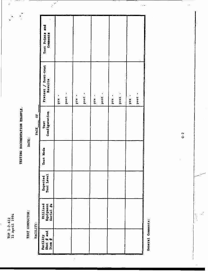
0
41144L
0 C1
E-4J
r44
4)4
1041 ). 0 -6 0 ) s
ý4 c
14)
0 0,
u0Q

TOP 1-2-61215 April 1994
TABLE# G-1: EXAMPLE HEMP CURRENT DATA.
Shot # Long Range W2 Current Pover Cable Peak CommentsAntenna Current (Amps) Current E-Field(Amps) (Amps) kV/m
3 11.59 16.68 3.646 52.06
4 11.52 14.31 3.885 50.54
5 12.00 17.81 3.664 51.88
6 11.10 12.27 3.835 52.36
7 11.55 14.19 3.993 52.18
8 12.13 12.27 3.624 52.13
9 11.12 12.53 3.718 53.03
10 11.87 12.65 3.768 52.58
11 12.06 12.56 4.029 52.99
12 11.69 12.76 3.879 51.38
13 12.09 12.38 3.867 52.27
14 11.93 12.72 4.140 53.29
15 12.00 12.64 3.739 51.73
16 12.21 12.58 3.557 51.94
17 12.37 12.59 4.019 51.24
18 11.82 12.55 4.025 53.69
19 11.86 12.53 4.260 52.81
20 11.89 12.49 3.971 52.15
21 11.63 12.49 4.005 52.15
22 12.64 12.29 4.005 53.03
23 11.96 12.09 3.835 52.44
24 12.85 12.59 4.164 53.00
25 11.84 12.36 3.974 53.65
26 12.18 12.23 3.849 52.84
27 11,76 12.09 4.240 53.08
G-3

TOP 1-2-61215 April 1994
TABLE# G-1: EXAMPLE HEMP CURRENT DATA (Continued).
Shot # Long Range W2 Current Power Cable Peak CommentsAntenna Current (Amps) Current E-Field(Amps) (Amps) kV/m
28 11.65 12.17 3.852 52.52
29 12.01 12.28 3.756 52.84
30 13.02 12.77 3.841 52.84
31 15.05 13.34 4.011 53.17
32 14.43 12.89 3.841 53.34
33 15.11 13.00 3.923 53.32
34 16.06 13.39 4.158 52.73
35 15.14 12.73 4.220 53.07
36 14.90 12.39 4.424 53.13
37 14.85 12.38 4.637 52.60
38 14.87 12.20 4.674 53.58
39 15.47 12.60 4.354 52.71
40 14.78 12.49 4.348 53.29
41 15.52 13.08 4.339 53.21
42 15.54 13.04 4.620 52.90
43 15.32 12.93 4.561 53.00
44 14.84 12.58 4.555 53.80
45 14.90 11.98 4.161 53.23
46 14.99 11.80 4.087 53.35
47 14.82 12.04 4.356 52.37
48 14.55 11.84 4.110 53.13
49 14.95 11.46 4.359 50.80
50 14.74 11.77 4.337 52.12
G-4

TOP 1-2-61215 April 1994
TABLE#I G-l: EXAMPLE CURRENT DATA (Continued).
Shot # Lcng Range W2 Current Power Cable Peak CommentsAntenna Current (Amps) Current E-Field(Amps) (Amps) kV/m
51 14.24 11.87 4.388 52.96
52 14.76 11.73 4.288 52.41
53 15.07 11.91 4.325 53.05
54 15.56 11.58 4.141 52.52
TABLE# G-2: STATISTICAL MANIPULATION ON EXAMPLE HEMP CURRENT DATA.
Long Range W2 Current Power Cable PeakAntenna (Amps) Current E-FieldCurrent (Amps) kV/m(Amps)
Mean 13.5183 12.6726 4.0877 52.650
Standard 1.59162 1.07913 0.2823 0.6961Deviation
G-5

TOP 1-2-61215 April 1994
T1 T2
T3
T4 T5
B1 B2
B3
B4 B5FIGURE G-1: EXAMPLE DOSIMETRY LOCATIONS.
G-6

TOP 1-2-612
15 April 1994
TABLE# G-3: (U) INITIAL DOCUMENTED PROBLEMS/FAILURES EXAMPLE.
Equipment without any Equipment with a BIT Test FailureProblems I Failures
1. S/N# 0001 1. S/N# 00022. SiN# 0003 2. SIN# 00043. S/N# 0005 3. S/N# 00064. S/N# 0007 4. S/N# 00085. SIN# 0031 5. S/N# 0009
6. S/N# 00107. S/N# 00118. S/N# 00129. S/N# 0030
All Pioblems and Failures are documented in the Table. S/N# 12 and 30 notUtilized because Effects on the NSA.
TABLE# G-4: (U) EXAMPLE EQUIPMENT TEST MATRIX.
Gamma Dose Neutron Total HEMPRate Fluence Gamma Dose EnvironmentEnvironment Environment Environment
Equipment # 0001 # 0001 # 0001 # 0001Tested at # 0003 # 0003 # 0003 # 0003Each of the # 0005 # 0007 # 0031 # 0009Environments # 0004 # 0006 # 0008 # 0011
# 0046 # 0010
G-7
TOP 1-2-61215 April 1994
APPENDIX H. ABBREVIATIONS
ALS - Advanced Schottky Logic
amp - Ampere
AMSAA - U.S. Army Materiel Systems Analysis Activity
APG - Aberdeen Proving Ground
APRF - Aberdeen Pulse Radiation Facility
AR - Army Regulation
ARES - Advanced Research Electromagnetic Simulator
ARL I - Army Research Laboratory
ASAP - As Soon As Possible
BOBs - Breakout Boxes
CaF2 (Mn) - Calcium Fluoride (Manganese)
Cal - Calorie
CCD - Charge Coupled Device
cGy - centiGray
CI - Current Injection
cm - centimeter
CML - Current Mode Logic
CMOS - Complimentary Metal Oxide Semiconductor
CMOS/SOS - Complimentary Metal Oxide Semiconductor/Silicon on Sapphire
CMOS/SOI - Complimentary Metal Oxide Semiconductor/Silicon on Insulator
COM - Center Of Mass
DAS - Data Acquisition System
DM - Design Margin
H-1
TOP 1-2-61215 April 1994
DNA - Defense Nuclear Agency
DOD - Department of Defense
DODI - Department of Defense Instruction
DT - Development Test
DT-II - Deveicpment Test II
DUT - Device Under Test
E - Total Energy Emitted
ECL - Emitter Coupled Logic
ECP - Engineering Change Proposal
EED - Electro-explosive Device
E-Field - Electric Field
EM - Electrcmagnetic
EMP - Electromagnetic Pulse
FAST - Fairchild Advanced Schottky TTL
FBR - Fast Burst Reactor
FFT - Fast Fourier Transform
FPS - Frames Per Second
FSD - Full Scale Development
FT - Gain Bandwidth Product
FWHM - Full Width Half Maximum
GHz - Gigahertz
GRF - Gamma Radiation Facility
Gy - Gray (100 RADs)
GZ - Ground Zero
HCI - Hardened Critical Item
H-2
TOP 1-2-612
15 April 1994
HE - High Explosive
HEMP - High Altitude Electromagnetic Pulse
HERMES - High Energy Radiation Megavolt Electron Source
HF - High Frequency
H-Field - Magnetic Field
HOB - Height of Burst
HPD - Horizontal Polarized Dipole
HQ - Headquarters
Hz - Hertz
IAP - Independent Assessment Plan
IAW - In Accordance With
IEP - Independent Evaluation Plan
INR Initial Nuclear Radiation
12L - Current Injection Logic
KAFB - Kirtland Air Force Base
kHz - Kilohertz
kPa - Kilo Pascals
kT - Kilo-ton
kV/m - Kilovolts Per Meter
LCNS - Life Cycle Nuclear Survivability Program
LF - Low Fr'quency
LINAC - LUnear Accelerator
LRU - Line Replaceable Unit
LST2 L - Low Power Schottky TTL
m - Meter
H-3

S
TOP 1-2-61215 April 1994
mA - Milliampere
MeV - Mega-electron Volt
MF - Middle Frequency
11Hz - Megahertz
MIL-STD - Military Standard
mm - Millimeter
MNOS - Metal Nitride Oxide Silicon
MNOS/SOS - Metal Nitride Oxide Silicon/Silicon on Sapphire
MOS - Metal Oxide Semiconductor
ms - millisecond
MSDS - Materiel Safety Data Sheets
NIA - Neutron Induced Activity
NLT - Not Later Than
NMOS - N-Channel Metal Oxide Semiconductor
ns - Nanosecond
NSA - Nuclear Survivability Analysis
NHC - Nuclear Hardening Criteria
ORD - Operational Requirements Document
P - Overpressure
PE - Project Engineer
PM - Program Manager
PMOS - P-Channel Metal Oxide Semiconductor
PMOS/SOS - F-Channel Metal Oxide Semiconductor/Silicon on Sapphire
Pc - Ambient Pressure
Psi - Pounds per square inch
H-4

TOP 1-2-612
15 April 1994
Psi-sec - Pounds per square inch-second
q - Dynamic Pressure
Q - Thermal Fluence
Qdot - Thermal Flux
QMR - Qualitative Materiel Requirement
QSTAG - Quadripartite Standardization Agreement
R - Range in centimeters
REBA - Relativistic Electron Beam Accelerator
RF - Radio Frequency
RAD - Radiation Absorbed Dose
Ref - Reference
REG - Regulation
ROC - Required Operational Capabilities
s, sec - second
SCTs - Shielded Cable Tests
Si . Silicon
SN - Serial Number
SNL - Sandia National Laboratories
SREMP - Source Region Electromagnetic Pulse
STT - Source-to-target
SubJ - Subject
- Transmissivity
TECOM - Test and Evaluation Command
TEM - Transverse Electromagnetic wave
TEMP - Test and Evaluation Master Plan
H-5
TOP 1-2-61215 April 1994
TIR - Test Incident Report
TLD - Thermoluminescent Dosimeter
TOP - Test Operations Procedure
TPD - Terminal Protection Device
TTL - Transistor - Transistor Logic
UHF - Ultra High Frequency
USA - United States Army
USANCA - United States Army Nuclear and Chemical Agency
Asec - microsecond
UV - Ultraviolet
VHF - Very High Frequency
VLF - Very Low Frequency
V/m - Volts pe: Minute
VPD - Vertical Polarized Dipole
WEST, - White Sands EMP System Test Array
WPAFB - Wright-Patterson Air Force Base
WSMR - White Sands Missile Range
H-6

& '
TOP 1-2-61215 April 1994
APPENDIX I. GLOSSARY
Absorption The process by which radiation imparts someor all of its energy to any material throughwhich it passes.
Attenuation The process by which a beam of radiation isreduced in intensity when passing throughsome material. It is the combination ofabsorption and scattering processes and leadsto a decrease in flux density of the beamwhen projected through matter.
Blast Wave A pulse of air in which the pressureincreases sharply at the front, accompaniedby winds, propagated continuously from anexplosion.
Beta Particle Charged particle emitted from the nucleus of anatom, with a mass and charge equal in magnitudeto that of the electron.
Calorie (gram-calorie) Amount of heat necessary to raise the temperatureof one gram of water 1 deg C (from 14.5 deg C)(abbreviation: cal)
Curie The unit quantity of any radioactive nuclidein which 3.7 x 10ElO disintegrations occur persecond.
Decay, Radioactive Disintegration of the nucleus of an unstablenuclide by spontaneous emission of chargedparticles and/or photons.
Dose A general term denoting the quantity ofradiation or energy absorbed. For specialpurposes, it must be appropriately qualified.If unqualified, it refers to absorbed dose.
Dosimeter Instrument to detect and measure accumulatedradiation exposure. A common dosimeter is apencil-size ionization chamber with a selfreading electrometer, used for personnelmonitoring.
Dynamic Pressure The air pressure which results from the massair flow (or wind) behind the shock front of
I-1

TOP 1-2-61215 April 1994
a blast wave. It is equal to the product ofhalf the density of the air through whichthe blast wave passes and the square of theparticle (or wind) velocity behind the shockfront as it impinges on an object, orstructure.
F ssion, Nuclear A nuclear transformation characterized by thesplitting of a nucleus into at least twoother nuclei and the release of a relativelylarge amount of energy.
Fusion, Nuclear Act of combining two or more atomic nucleiinto a heavier element, releasing substantialamounts of energy.
Gamma, Prompt Gamma radiation emitted at the time of fissionof a nucleus.
Gamma Ray Short-wavelength electromagnetic radiation ofnuclear origin (range of energy from 10 Keyto 9 Mev) emitted from the nucleus.
Impulse (per unit area) The integral, with respect to time, of theoverpressure (or dynamic pressure), theintegration being between the time of arrivalof the blast wave and that at which theoverpressure (or dynamic pressure) returns tozero at the given point.
Ionization The process by which a neutral atom or moleculeacquires a positive or negative charge.
Isotopes Nuclides having the same number of protons intheir nuclei, and hence the same atomic number,but differing in the number of neutrons,and therefore in the mass number. Isotopesof the same element have almost identicalchemical properties.
Mev One million electron volts (10E6 ev). An electronvolt is the amount of energy acquired byan electron when it falls through a potentialof 1 volt.
Neutron A neutral particle of approximately oneatomic mass unit, present in all atomicnuclei except those of ordinary hydrogen.
1-2
TOP 1-2-61215 April 1994
Neutron Flux The product of the neutron density and theneutron velocity, expressed as neutrons perunit area per unit time.
Nuclear Radiation Particulate and electromagnetic radiationemitted from atomic nuclei in various nuclearprocesses. The important nuclear radiationsfrom the weapon detonations are gamma, alphaand beta particles, and neutrons.
Overpressure The transient pressure that exceeds ambientconditions. It is manifested in the shock orblast wave from an explosion. Usuallyexpressed in pounds per square inch (psi).
Thermal Radiation Electromagnetic radiation emitted (in twopulses from an air burst) from the fireballas a consequence of its high temperature; itconsists essentially of ultraviolet, visible,and infrared radiations. In the early stages(first pulse of an air burst), when the tem-perature of the fireball is extremely high,the ultraviolet radiation predominates; inthe second pulse, the temperatures are lowerand most of the thermal radiation lies in thevisible and infrared regions of the spectrum.From a high-altitude burst, the thermal radiationis emitted in a single short pulse.
X-rays Penetrating electromagnetic radiations whosewavelengths are shorter than those of visiblelight. They are usually produced by bombardinga metallic target with fast electrons inhigh vacuum. In nuclear reactions, it iscustomary to refer to photons originating inthe nucleus as gamma rays and those originatingin the extranuclear part of the atom asx-rays. These rays are sometimes called roentgenrays after their discoverer, W. C. Roentgen.
1-3

TOP 1-2-612
15 Apri7. 1994
APPENDIX J. REFERENCES
REQUIRED REFERENCES
1. DASIAC SR-90-252, 1990 Edition, Guide to Nuclear Weapons Effects SimulationFacilities and Techniques.
2. Annual Book of ASTM Standards, Section 12.
3. TECOM Pamphlet 73-1, Developmental Test and Assessment Guide, 30 Sep 93.
4. AR 70-60, Nuclear Survivability of Army Materiel, 1 Nov 84.
5. DODi 5000.2, Defense Acquisition Program Procedure~s, 11 nay 90.
6. MIL-STD-461C, Electromagnetic Emission and Susceptibility Requirements forthe Control of Electromagnetic lIterference.
7. MIL-STD-461D, Electromagnetic Emission nnj Susceptibility Requirements forthe Control of Electromagnetic Inteiference.
8. MIL-STD-883, Test Methods and Procedures for Microelectronics, 18 Dec 89.
9. MIL-STD-750, Test Methods and Procedures for Semiconductor Devices, 17 Dec87.
10. QSTAG 244, Edition 3, Nuclear Survivability Criteria for hilitary Equipment,27 Oct 80.
11. QSTAG 244, Edition 4, Nuclear Survivability Criteria for Military Equipment,19 January 1993.
12. QSTAG 620, Nuclear Survivability Criteria foz Communications-ElectronicsEquipment, 27 Oct 80.
13. QSTAG 620, Edition 2, Nuclear Survivability Criteria for Communications-Electronics Equipment, 29 January 1993.
14. MIL-STD-2169A, Fast Electromagnetic Pulse, Oct 87.
15. Draft TOP 1-2-615, Nuclear Effects Testing of Army Materiel (EMP), 30 Sep92.
16. TOP 1-2-618, Initial Nuclear Radiation Testing, 15 Feb 93.
17. Draft TOP 1-2-620, High-Altitude Electromagnetic Pulse Tests, 30 Sep 92.
J-1

/
t
TOP 1-2-61215 April 1994
REFERENCES FOR INFORMATION ONLY
a. TECOM Regulation 37-1, TECOM Test Cost Estimates, 24 March 1984.
b. Draft TECOM Regulation 70-8, Test Resource Management System, 20 May 92.
c. AR 200-1, Environmental Protection and Enhancement, 23 May 90.
d. AR 200-2, Environmental Effects of Army Actions, April 90.
e. AMR-C 385-100, Safety Manual, 8 May 92.
f. G.C. Messenger and M.S Ash, The Effects of Radiation on Electronic Systems,published by Van Nostrand Reinhold, 1986.
g. S. Glasstone and P.J. Dolan, The Effects of Nuclear Weapons, published byUnited States Department of Defense and United States Department of: Energy, 1977.
h. L.W. McNaught, Nuclear Weapons and Their Effects, published by Brassey'sDefence Publishers, 1977.
J-2

SJ
TOP 1-2-61215 April 1994
Recommended changes of this publication should be forwarded toCommander, U.S. Army Test and Evaluation Command, ATTN: AMSTE-CT-T, Aberdeen Proving Ground, MD 21005-5055. Tech.ticalinformation may be obtained by the preparing activity:Commander, U.S. Army White Sands Missile Range, ATTN: STEWS-NE-A, WSMR, NM 88002. Additional copies are available fromthe Defense Technical Information Center, Cameron Station,Alexandria, VA 22304-6145. This document is identified by theaccession number (AD No.) printed on the first page.
SUPPLEMENTAI V%
INFORMATICO

... .... ,.
C1. TOP 1-2-612DEPARTMENT OF "HE ARMY
, EAD(AE. U.S. ARMY TEST AYD EVALUATION COMA)Aberdeen Proving Ground. Maryland 21005-5055
Change 1 nAl A h /° , 6 5,'7 5 February 1997TOP 1-2-612 ' 6 Z 2-AD No. A278230
Test Operations ProcedureNUCLEAR ENVIRNM T SURVIVABILITY
TOP 1-2-612. 15 April 1994, is changed as follows:
1. Make the following pencil/ink changes:
a. Block 9 of Standard Form 298, Report Documentation Page, and AddressChange Block on last page of document, changed to: Cummander. U.S. Army Test andEvaluation Command. ATTN: AMSTE-TM-T, Aberdeen Proving Ground. MD 21005-5055.
b. Page 3. paragraph 2.1.2. lines 26-28. Change "SR-90-252" to "SR-94-009";on line 27/28, change "(1990 Edition) on pages 2-4 through 2-48." to "(1995Edition) on pages 2-7 through 2-41."
* c. Page 5. paragraph 2.2.2, line 35. Change "SR-90-252 on pages 3-4 through3-18.N to "SR-94-009 on pages 3-4 through 3-17."
d. Page 7, paragraph 2.3.2: Delete under facility item 5.
e. Page 7. renumber item "6" to "5" and change under Comments column "MIL-STD 2169A" to "MIL-STD 21698".
f. Page 7, renumber item "7" to "6".
g. Page 7. last paragraph, line 2/3. Change "SR-90-252" to "SR-94-009" andon line 3, page number "4-54" to '4-32."
h. Page 9. paragraph 2.4.2. line 19/20. Change wording "SR-90-252 on pages5-63 through 5-128." to "SR-94-009 on pages 5-58 through 5-122."
i. Page 11. paragraph 2.5.2. line 19/20. Change wording "SR-90-252 on pages5-42 through 5-62." to "SR-94-009 on pages 5-42 through 5-51."
J. Page 12. paragraph 2.5.3. line 8. Change to read after the number E722"(specifically E722-93) must be referenced."
k. Page 12, paragraph 2.6.1, line 13/14. Delete the following sentence"With this value of Di, the PE must subtract the neutron dose contribution." andreplace with "In addition, the correct utilized value should have in quotes(single pulse duration of 60 seconds)."
1. Page 13, paragraph 2.6.2. line 22/23. Change wording "SR-90-252 on pages5-9 through 5-41. to "SR-94-009 on pages 5-8 through 5-34."
"i'""' i i iI ; II !
C1, TOP 1-2-612 5 February 1997
m. Page 14, paragraph 3.1.2, change line 1 through 4 to read: CostEstimates. Upon devising an appropriate test scenario a TECOM cost estimate (STEForm 1195) must be prepared IAW TECOM REG. 73-3b, Test Resource Management System(TRMS).
n. Page 52, paraqraph 6.1.e: Change subparagraph e "MIL-STD-2169A: FastElectro-ignetic Pulse- ." to "MIL-STD-21698: High Altitude Electromagnetic Pulse(HEMP) Envi ronm ent 4.
o. Page J-1, item 1, line 1: Chaige "SR-90-252, 1990" to "SR-94-009, 1995"
p. Page J-1. item 4: Change to read: AR 70-75, Survivability of ArmyPersonnel and Materiel, 10 Jan 95.
q. Page J-1, item 5: Change to read: DODI 5000.2-R, Defense AcquisitionManagement Policies and Procedures, 23 Feb 91.
r. Page J-1, item 6: Delete all.
s. Page J-1, rentumber "7 through 17" to "6 through 16"
t. Page J-1, new item 6: Add at end "11 Jan 93"
u. Page J-1, new item 7: Change to read: MIL-ST1-183D(3) Microcircuits,14 Mar 95.
v. Page J-1, new item 8: Change to read: MIL-STD-750D(1) Test Methods andProcedures for Semiconductor Devices, 18 May 95.
w. Page J-3. new item 13: Change to read: MIL-STD-2169B High AltitudeElectromagnetic Pulse (HEMP) Environment, Dec 93.
x. Page J-1, new item 15: Change date "15 Feb 93" to "29 Oct 93"
y. Page J-2: Delete all of item "a"
z. Page J-2. change all b. to read: "a. TECOM Regulation 73-3, TestResource Management System (TRMS), 12 Nov 93 and change 1, 9 Aug 95".
aa. Page J-2, enter new item: "b. TECOM Pam 73-3, Test Resource ManagementSystem (TRMS), 15 Jul 96".
bb. Page J-2, item c: Change date "23 May 93" to "23 Apr 93".
cc. Page J-2. item d: Change date "Apr 90" to "23 Dec 88".
dd. Page J-2, item e: Change to read: AMC-C 385-100, Safety Manual, 26 Sep95.
20

. C1. TOP 1-2-612 . ... 5 February 1997
ee. Last page, change address block, lines 7 through 9 to read: 'the DefenseTechnical Information Center, 8725 John 3. Kingman Rd.. STE 0944, Fort Belvoir,VA 22060-6218. This document is identified by the accession number (AD No.)printed on the first page."
2. After posting the changes, file Change Sheets in front of the TOP forreference.
* 3
/.
/7
DATC: