ad-alol 244 unclassified ehheeidiiii~hi national dam l
TRANSCRIPT

AD-AlOl 244 D'APPOLONIA CONSULTING EN61NEERS INC PITTSBURGH PA F/6 13/13NATIONAL DAM INSPECTION PROGRAM. PA-RC A D-105 DAM (NDI I.D. PA-ETC(U(1981 L 0 ANDERSEN DACW31-81-C-O014
UNCLASSIFIED NLEhhEEIDIIII~hIElE~llEEllEEEEIIIIIIIIIIIl-IEllllEllllEEEI
IEI~m~hhhhEEE'ElF'c

PENNSYLVANIAI
__ ERig D. A-979OERID 58438)SLPht1% "
~ 2HASE II SPECTION.4EPORT
AL AMINPETIT ROCA
Iwo2 w111 be in blaok S8flO'.PREARE F
DEPARTMENT OF THE ARMYBALTIMORE DISTRICT, CORPS OF ENGINEERS
BALTIMORE, MARYLAND 21203
* DAPPOLONEA CONSULTING ENGINEERS'10 DUFF ROAD
PWTS3VRGN, PA. 15235
.IIWDUIO for T puWWot"
bl~bto Tjn 014 a J.Af
PREFACE
This report is prepared under guidance contained in the RecommendedGuidelines for Safety Inspection of Dams, for Phase I Investigations.Copies of these guidelines may be obtained from the Department ofthe Army, Office of Chief of Engineers, Washington, D.C. 20314.
The purpose of a Phase I investigation is to identify expeditiouslythose dams which may pose hazards to human life or property. Theassessment of the general condition of the dam is based upon visualobservations and review of available data. Detailed investigations
and analyses involving topographic mapping, subsurface investigations,material testing, and detailed computational evaluations are beyondthe scope of a Phase I investigation; however, the inspection isintended to identify any need for such studies which should be per-formed by the owner.
In reviewing this report, it should be realized that the reportedcondition of the dam is based on observations of field conditions atthe time of inspection along with data available to the inspectionteam. In cases where the reservoir was lowered or drained prior toinspection, such action, while improving the stability of the dam,removes the normal load on the structure and may obscure certainconditions which might otherwise be detectable if inspected underthe normal operating environment of the structure.
it is important to note that the condition of the dam depends onnumerous and constantly changing internal and external factors whichare evolutionary in nature. It would be incorrect to assume thatthe present condition of the dam will continue to represent the condi-tion of the dam at some point in the future. Only through frequentinspections can unsafe conditions be detected and only through continuedcare and maintenance can these conditions be prevented or corrected.
Phase I inspections are not intended to provide detailed hydrologicand hydraulic analyses. In accordance with the established Guidelines,the spillway design flood is based on the estimated "Probable MaximumFlood" for the region (greatest reasonably possible storm runoff), orfractions thereof. The spillway design flood provides a measure ofrelative spillway capacity and serves as an aid in determining the needfor more detailed hydrologic and hydraulic studies, considering the sizeof the dam, its general condition and the downstream damage potential.
The assessment of the conditions and recommendations was made by the.1I consulting engineer in accordance with generally and currently acceptedengineering principles and practices.
I
Ii i

PHASE I REPORTNATIONAL DAM INSPECTION PROGRAM
NAME OF DAM: PA-RC&D-105 DamSTATE LOCATED: PennsylvaniaCOUNTY LOCATED: SusquehannaSTREAM: Thomas Creek, a secondary tributary of the Susquehanna RiverSIZE CLASSIFICATION: SmallHAZARD CLASSIFICATION: HighOWNER: Susquehanna County CoumissionersDATE OF INSPECTION: November 13, 1980 and February 5, 1981
ASSESSMENT: Based on the evaluation of the existing conditions,the condition of PA-RC&D-105 Dam is considered to be good.
The flood discharge capacity was evaluated according to the recoumendedcriteria and was found to pass full PMF without overtopping the embank-ment. Therefore, the spillway capacity is rated to be adequate.
The following reco-mmendations should be implemented on a continuingbasis.
1. Around-the-clock surveillance should beprovided during unusually heavy runoff and aformal warning system should be developed toalert the downstream residents in the eventof emergencies.
2. The dam and appurtenant structures shouldcontinue to be inspected regularly andnecessary maintenance performed.
j-:': .. :. C: Co es ___
H ni/or
Dit
iii b,;::: a

Assessment -PA-i<C&D-]05 Dami
La rar~ic D. ATI(!er.,, ii, P.E.
Vicfp I o!;i.rnt
[)at<
Approved by:
("O1Cm , Cerps of ETngine-rL,IConimaodi and DWstricr EiiginLt..r
4 ~~--------------------------------Da re:
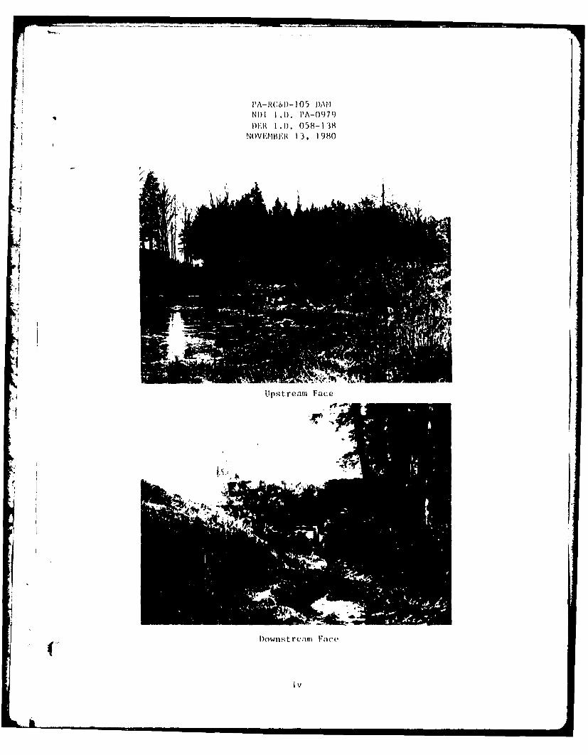
PA-RL:&D-1I05 i)AINIl 1.DI. PA-0979I)ER 1.1). 058-138
NoVEMBER 1 3, 1980
Upstream Face
D~ownst ream Facec
iv

TABLE OF CO)NTENTS
PAGE
SECTION I - PROJECT INFORMATION 1
1.1 General 11.2 Description of Project I1.3 PertiAent Data 2
SECTION 2 - DESIGN DATA 4
2.1 Design 42.2 Construction 52.3 Operation 52.4 Other Investigations 52.5 Evaluation 5
SECTION 3 - VISUAL INSPECTION 7
3.1 Findings 73.2 Evaluation 7
SECTION 4 - OPERATIONAL FEATURES 8
4.1 Procedure 84.2 Maintenance of the Dam 84.3 Maintenance of Operating Facilities 84.4 Warning System 84.5 Evaluation 8
SECTION 5 - HYDRAULICS AND HYDROLOGY 9
5.1 Evaluation of Features 9
SECTION 6 - STRUCTURAL STABILITY 10
6.1 Evaluation of Structural Stability 10
SECTION 7 - ASSESSMENT AND RECOMMENDATIONS/PROPOSED REMEDIAL MEASURES 11
7.1 Dam Assessment 117.2 Recommendations/Remedial Measures 11
Vv

TABLE OF CONTENTS(Coat inued)
APPENDIX A - CHECKLIST, VISUAL INSPECTION, PHASE IAPPENDIX B - CHECKLIST, ENGINEERING DATA, DESIGN, CONSTRUCTION,
OPERATION, AND HYDROLOGIC AND HYDRAULIC, PHASE IAPPENDIX C - PHOTOGRAPHSAPPENDIX D - HYDROLOGY AND HYDRAULICS ANALYSESAPPENDIX E - PLATESAPPENDIX F - REGIONAL GEOLOGY
v
!vi

PHASE I REPORTNATIONAL DAM INSPECTION PROGRAM
PA-RC&D-105 DAMNDI I.D. PA-0979DER I.D. 058-138
SECTION 1
PROJECT INFORMATION
1.1 General
a. Authority. The inspection was performed pursuant to theauthority granted by The National Dam Inspection Act, Public Law 92-367,to the Secretary of the Army, through the Corps of Engineers, to conductinspections of dams throughout the United States.
b. Purpose. The purpose of this inspection is to determine ifthe dam constitutes a hazard to human life or property.
1.2 Description of Project
a. Dam and Appurtenances. PA-RC&D-105 Dam is a part of theSpringville Flood Prevention Project. The dam consists of an earthembankment approximately 200 feet long with a maximum height of 24 feetfrom the downstream toe and a crest width of 12 feet. Both the upstreamand downstream slopes of the dam are covered with grass and have slopesof 3H:lV with a 12-foot berm on the upstream slope near normal poollevel.
The flood discharge facilities of the dam consist of a drop inlet pri-
mary spillway located near the center of the embankment and an emergencyspillway located on the right abutment. The primary spillway is a dropinlet structure consisting of a two-stage reinforced concrete riser anda 30-inch-diameter reinforced concrete conduit, terminating at a rein-
forced concrete impact basin energy dissipating structure at the down-stream toe of the dam. The outlet pipe is supported on a concretecradle equipped with five antiseepage collars spaced at 20-foot inter-vals along the upstream two-thirds of the pipe. The emergency spillwayis a grass-lined trapezoidal channel with a base width of 60 feet. A30-foot-wide level section extending across the emergency spillwaychannel constitutes the overflow section.
b. Location. PA-RC&D-105 Dam is located across Thomas Creekapproximately one-quarter mile upstream from Springville, in SpringvilleTownship, Susquehanna County, Pennsylvania (N41* 42.1', W75 ° 55.5').Plate I illustrates the location of the dam.
c. Size Classification. Small (based on 24-foot height and 342acre-feet maximum storage capacity).
' , . .C . . .. .. .. . .. , . . . . . . I I n i ~ l .. ... [ i

d. Hazard Classification. The dam is classified to be in thehigh hazard category. Below the dam, Thomas Creek flows under a high-way (LR57012) approximately 1,000 feet downstream from the dam andshortly thereafter flows through the urban residential area of Spring-ville. It is estimated that failure of the dam under maximum pool levelwould cause loss of more than a few lives and property damage in thedownstream residential areas.
e. Ownership. Susquehanna County Commissioners (address: Mr.James Adams, Chairman, Susquehanna County Commissioners, Court House,Montrose, Pennsylvania 18801).
f. Purpose of Dam. Flood control.
g. Design and Construction History. The dam was designed bythe U.S. Department of Agriculture, Soil Conservation Service, during1974. Construction of the dam was completed in 1978.
h. Normal Operating Procedure. The reservoir is normally main-tained at Elevation 1254.9, the crest level of a two-foot-high andone-foot-wide orifice on the upstream face of the drop inlet structure.The crest level of the primary spillway is at Elevation 1260.6. Thecrest of the emergency spillway is at Elevation 1260.8. Depending on therate of inflow, the flood would be discharged through the orifice incombination with the primary and emergency spillways.
1.3 Pertinent Data
a. Drainage Area 0.6 square mile
b. Discharge at Dam Site (cfs)
Maximum known flood at dam site UnknownOutlet conduit at maximum pool 118Gated spillway capacity at maximum pool Not applicableUngated spillway capacity at maximum pool 3580Total spillway capacity at maximum pool 3580
c. Elevation (USGS Datum) (feet)
Top of dam 1267.2 (as measured)1266.8 (as designed)
Maximum pool 1266.8Normal pool 1254.9Upstream invert outlet works 1249.1Downstream invert outlet works 1242.9Streambed at center line of dam 1243±.Maximum tailwater Unknown
d. Reservoir Length (feet)
Normal pool level 1400±Maximum pool level 1500±
2

e. Storage (acre-feet)
Normal pool level 50 (estimated)Maximum pool level 342
f. Reservoir Surface (acres)
Normal pooi level 161~
Maximum pool level 301
g. Dam
Type EarthLength 200 feetHeight 24 feetTop width 12 feetSide slopes Downstream: 3H:lV
Upstream: 3H:IVZoning NoImpervious core No
Cutoff YesGrout curtain No
h. Regulating Outlet
Type 18-inch reinforcedconcrete pipe
Length 20 feet to dropinlet
Closure Sluice gate at dropinlet structure
Access Drop inlet struc-ture
Regulating facilities Sluice gate
i. Spillway Primary:(1) Emergency:
Type Drop inlet Trapezoidalearth channel
Width 15 feet 60 feetCrest elevation 1260.6 1260.8Gates None NoneUpstream channel Lake Trapezoidal
earth channelDownstream channel 30-inch outlet Trapezoidal
reinforced concrete earth channelconduit
2'
(')Normal pool is maintained at the crest level of a two-foot-wide andt one-foot-high orifice on the drop inlet at Elevation 1254.9.
3

SECTION 2DESIGN DATA
2.1 Design
a. Data Available. The available information was provided by
the Pennsylvania Department of Environmental Resources (PennDER), andincludes design drawings, reports, and correspondence.
(1) Hydrology and Hydraulics. The available informationconsists of principal, freeboard, and emergency spillway inflowhydrographs and the results of associated flood routings.
(2) Embankment. The available information consists of designdrawings, geology and soils reports, laboratory soils test results, andthe results of slope stability and seepage analyses.
(3) Appurtenant Structures. The available informationincludes design drawings.
b. Design Features
(I) Embankment. Plates 2 and 3 illustrate the plan of theembankment and the appurtenant structures. As shown in Plate 4, the damconsists of a homogeneous earth embankment with a trench drain locatedbeneath the downstream slope.
The dam was designed to have a 3:1 (horizontal to vertical) slopedownstream and upstream. A 12-foot-wide berm on the upstream slope islocated at approximately the midheight of the dam.
The subsurface investigation conducted for the dam consisted of numerousborings and test pits. The locations of these borings are shown in Plate
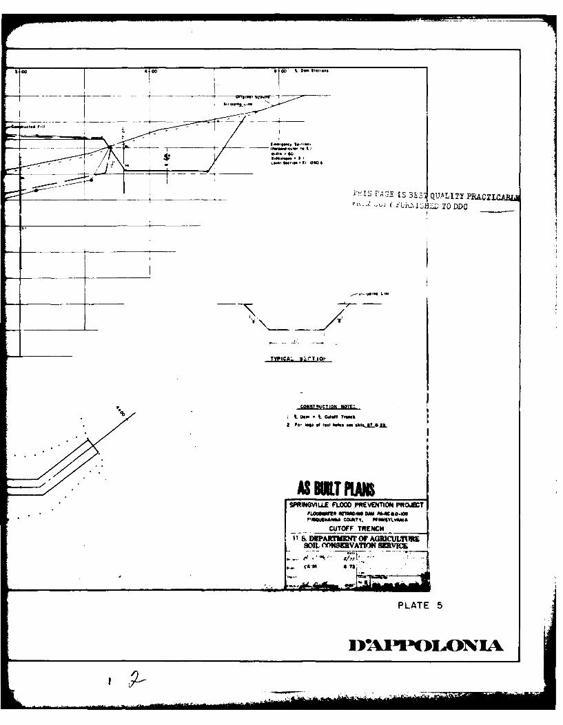
3. Plate 5 shows the typical subsurface profile. The typical subsurfaceprofile consists of 20 feet of medium stiff to hard sandy clayey silts onthe valley sides and about 15 feet of loose to dense sand and gravel andclayey sands in the valley bottom. The rock beneath the site includessiltstone and sandstones. In the valley bottom, sandstone was encounteredto a depth of approximately 15 feet. It is reported that the permea-bility of the sandy clayey silt was found to be low, ranging from 0.1to 0.9 foot per day (4 x 10- 5 cm/sec to 3 x 10⁻⁴ cm/sec). Thesepermeabilities were measured at depths ranging from 4 to 22 feet.Details of the downstream slope trench drain are included in Plate 6.
(2) Appurtenant Structures. The appurtenant structures of the damconsist of a drop inlet primary spillway and an emergency spillway. Theprimary spillway structures include a two-stage reinforced concrete riserand a 30-inch-diameter reinforced concrete conduit through the embankmentterminating at a reinforced concrete impact basin at the downstream toe
of the dam (Plates 7, 8, and 9). An 18-inch reinforced concrete pipe
4

from the upstream toe of the dam, discharging into the drop inletstructure, constitutes the reservoir outlet facilities. Flow through thereservoir outlet pipe is controlled by a sluice gate located in the dropinlet structure. The outlet conduit is supported on a continuous concretecradle with five reinforced concrete cutoff collars.
The emergency spillway is a trapezoidal earth channel excavated into theright abutment (Plate 2). The bottom width of the trapezoidal channel is60 feet with side slopes of 3H:IV. A 30-foot-wide level section locatedat Elevation 1206.8 constitutes the control section of the spillway.
c. Design Data
(1) Hydrology and Hydraulics. Available information indicatesthat the emergency spillway was designed to pass a freeboard hydrographwith a peak of 4647 cfs, corresponding to 24.3 inches of precipitationin six hours without overtopping the embankment. This hydrograph wasrouted through the reservoir starting at normal pool (Elevation 1254.9),producing a maximum pool level at Elevation 1266.8 with a peak emergencyspillway outflow of 2719 cfs. The top of the dam was established atElevation 1266.8.
(2) Embankment. Available information indicates that the designof the embankment was based on the evaluation of site geology, subsurfaceconditions, and laboratory index and strength tests.
(3) Appurtenant Structures. The available information indicatesthat the appurtenant structures were standard Soil Conservation Service(SCS) designs.
2.2 Construction. As-built drawings and construction progress reportswere available for review. To the extent that can be determined, theconstruction of the dam was in conformance with SCS specifications. Nounusual construction difficulties were reported. The dam was constructedunder the supervision of an SCS field representative. It is reported thatthe earthwork was monitored by field density tests. However, the resultswere not available for review.
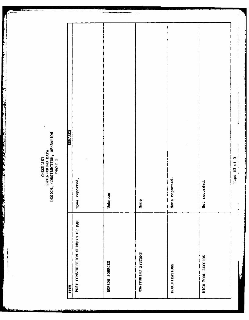
Available information indicates no postconstruction changes.
2.3 Operation. No records of operation are kept.
2.4 Other Investigations. None reported.
2.5 Evaluation
a. Availability. Available information was obtained from PennDER.
b. Adequacy
(1) Hydrology and Hydraulics. The available information is con-sidered to be adequate to assess the conformity of the design to thecurrent spillway design criteria.
5
(2) Embankment. Review of the geotechnical aspects of the designindicates that the design generally followed currently accepted prac-tice for subsurface investigation, laboratory testing, analysis, andconstruction.
(3) Appurtenant Structures. Review of the design drawings indicatesthat the appurtenant structures were designed and constructed in conform-ance with currently accepted engineering practices.
li
( 6
SECTION 3VISUAL INSPECTION
3.1 Findings
a. reneral. The onsite inspection of PA-RC&D-105 Dam consistedof.
1. Vi,ual inspection oi the embankment, ,bltments,and embankmeat toe.
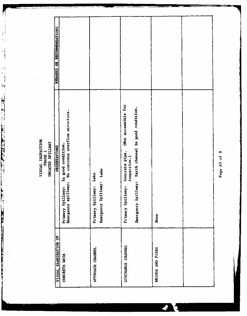
2. Visua. examination of the emergency spillwayand visible portions of the primary spillway.
3. Evaluation of downstream area hazard potential.
Th: specific observations are illustrated in Plate 10.
b. Embankment. The general inspection of the embankmeni consistedof searching for indications of structural distress, such as cracks,subsidence, bulging, wet areas, seeps and boils, and observing generalmaintenance condi.ions, vegetative cover, erosion, and ither surficiafeatuzes.
In general, LIe condition of the dam i. considered to be good. Noseepage or other Aigns of distress were observed during inspection. Someminor erosion gcars were fo',nd o the upsrreau and downstream faces ofthe dma
The top of the dam was surveyed relative to the emergency spillway crestelevation and was found to be within 0.2 foot of the design elevationwith cawber. Platc !s&hows the daw crcst profile.
c. ApuiLena*nt Structures. The appurtenant strucLures wereexamined for 6f'tarioration or other signs of distress anc obstructionseiat would limit flow. The ttruc.ures were found _o be in good coL.ii-tion. No deficiencies were noted at this time.
d. Reservo;r Area. A map reviLw indicates that the watershed ispredominantly covered with woodlands. A review of the regional geologyis incluaeJ in Appendix F.
e. Downstream Channel. Downstream from the dam, Thomas Creekflows approximately 2,000 feet southeast where it passes through residen-tial areas of S~ringville. Further description of downstream conditionsis included in Section 1.2 d.
3.2 Evaluation. The dam was found to be in good condition and adequatelymonitored.
7

SECTION 4OPERATIONAL FEATURES
4.1 Procedure. The reservoir is normally maintained at the primaryspiliway orifice level with excess inflow discharging through the
orifice. The reservoir outlet pipe can be used to draw down the permanentpool when required. The reservoir outlet pipe gate is normally closed.
4.2 Maintenance of the Dam. The maintenance of the dam is consideredto be good. The downstream and upstream faces of the dam arecovered with grass and appear to be annually mowed.
4.3 Maintenance of Operating Facilities. The only operational featureof the dam is the reservoir outlet pipe sluice gate operated by a hoistlocated on the primary spillway drop inlet structure. Since the top ofthe drop inlet structure was not accessible, this facility could not beclosely examined.
4.4 Warning System. No formal warning system exists for the dam.Telephone communication facilities are available via residences at thedam site.
4.5 Evaluation. The maintenance condition of the dam is consideredto be good.
8

SECTION 5HYDRAULICS AND HYDROLOGY
5.1 Evaluation of Features
a. Design Data. PA-RC&D-105 Dam has a watershed of 0.6 squaremile and impounds a reservoir with a surface area of 16 acres at normalpool level. The emergency spillway of the dam is located on the rightabutment. The capacity of the emergency spillway is calculated to be3580 cfs with no freeboard.
b. Experience Data. As previously stated, PA-RC&D-105 Dam is
classified as a small dam in the high hazard catetory. Under the
recommended criteria for evaluating emergency spillway discharge capacity,such impoundments are required to pass one-half to full Probable MaximuFlood (PMF). In view of the high downstream drainage potential, full PMF
was selected as the spillway design flood.
The PMF inflow hydrograph for the reservoir was determined using the
Dam Safety Version of the EEC-i computer program developed by the Hydro-
logic Engineering Center of the U.S. Army, Corps of Engineers. The dataused for the computer input are presented in Appendix D. The PMF inflow
hydrograph was found to have a peak flow of 1590 cfs. The computer
outputs are included in Appendix D.
c. Visual Observations. On the dates of inspection, no conditionswere observed that would indicate that the emergency spillway capacitywould be significantly reduced in the event of a flood.
d. Overtopping Potential. PMF inflow hydrograph was routedthrough the reservoir and it was found that the dam can pass 100 percent
PMF without overtopping.
e. Spillway Adequacy. The spillway can pass the recommendedspillway design flood of full PMF without overtopping the embankment;therefore, the spillway capacity is classified to be adequate accordingto the recommended criteria.
4: 9
SECTION 6STRUCTURAL STABILITY
6.1 Evaluation of Structural Stability
a. Visual Observations
(1) Embankment. As discussed in Section 3, the field observationsdid not reveal any signs of distress that would significantly affect thestability of the embankment at this time. However, it should be under-stood that since the dam is a flood control facility and was at normal(low level) pool at the time of inspection, it was not under maximumloading conditions. Maximum loading occurs only during the passage ofmajor floods.
(2) Appurtenant Structures. Performance of the appurtenantstructures is considered to be satisfactory.
b. Design and Construction Data
(1) Embankment. Available information indicates that the stabilityof the embankment was analyzed for steady seepage and rapid drawdownconditions using the modified Swedish circle and sliding block slopestability analysis procedures. The minimum factor of safety was reportedto be 2.1 for the steady-state seepage stability of the downstream slopeand 1.4 for the rapid drawdown condition of the upstream slope. Strengthparameters for the core material were obtained from consolidated-undrainedtriaxial shear tests with pore pressure measurements. Assumed strengthparameter values were used for the shell materials. Constructionprogress reports indicate that the dam was constructed under the super-vision of an SCS field representative, and the earthwork was monitoredby field density tests.
(2) Appurtenant Structures. Review of the design drawings indi-cates that there are no apparent structural deficiencies that wouldsignificantly affect the performance of the appurtenant structures.
c. Operating Records. There are no operating records kept for
the dam.
d. Postconstruction Changes. None reported.
e. Seismic Stability. The dam is located in Seismic Zone 1,and based on visual observations, the static stability of the dam isconsidered to be adequate. Therefore, based on the recommended criteriafor evaluation of seismic stability of dams, the structure is presumedto present no hazard from earthquakes.
10
10m

SECTION 7ASSESSMENT AND RECOMMENDATIONS/PROPOSED REMEDIAL MEASURES
7.1 Dam Assessment
a. Assessment. The visual observations indicate that PA-RC&D-105Dam is in good condition. No conditions were observed that wouldsignificantly affect the overall performance of the structure at thistime. However, as previously noted, the dam was not inspected under itsmaximum loading condition, which would occur when the reservoir isfilled during major storms.
The spillway can pass the required spillway design flood and is, therefore,classified to be adequate according to the recommended criteria.
b. Adequacy of Information. Available information, in conjunctionwith the visual observations, is considered to be sufficient to makea Phase I evaluation.
Sc. Urgency. The following recommendations should be implementedon a continuing basis.
d. Necessity for Additional Investigation. No additional investi-
7.2 Recomendations/Remedial Measures. It is recommended that:
1. Around-the-clock surveillance should be providedduring unusually heavy runoff and a formal warningsystem should be developed to alert the downstreamresidents in the event of emergencies.
2. The dam and appurtenant structures shouldcontinue to be inspected regularly andnecessary maintenance performed.
11

APPENDIX A
CHECKLISTVISUAL INSPECTION
i PHASE I

cn
+1
'-4
040
E-
sn
0 0
004
E-00
E-4 z
0 -H
t; cc 1-4 Go0144 1- 0 4
04 430 $
*1~~ C- -
4: cc
41 0
"4
0 >z oH
wc -W r-4f
4-4 24 0- -H1
OZ 0
w -3 A
o (n% 0
z E-4 c'

z
00
0
> w0
0-0
00
00 w.
0)041.
0 0 0 JJJ.
44 4.4 44-3."4
41 0 0 w0
0 0 0 00
Ow .E-4
-E
00 ra U
0
- TAd

z
00
00
00
00 1.0
0 $
c.O E-4 1
rzI-4 O .1- 0%04 w
~I20 El-2~6 *~ 4*
ra0
cn0

D0
o 0040
00
4.5
009
-r4
z 0000
CZ 00
I.44
E-4 0
1 0 IT
G) 41-4 m
-r4 0
0 W0
-A 0
~ 0 00
0 >
u 0 1.0
cc, 0 0 4.0CI. b4 0.0
40 0 A
0 0 c0z z0
en4 G.94 -94 CL
GD 4. 4.5.0 H
E- w OW 0) 0
4.5E 045 tH F.
>
00
>4.tn 0
V) pa4 P4 VC1-4 0 C
C: - -
J0 w 000 )cc0, 0
0d 0C
4 -4
-4 1-. -4 M
to 00
41 4) 945
00
4-4 0-4

z
4 4
0 -
0
I
ot
E-4 z
C.,. q i
rd 0
C~n wE--4
w
Adu o c0n zco"1 -O
>
ILL

C
4U
'1 0 0
0- 0z- 2
rz-z >

0
00
0- 0~
040
a)
a)-0j

00
140
1.44
-4
1.0
Z4 0-0-4
4.
co 0
IV 004.40
0 0 co10
.0 .0 1.
00 )0
z - 04
0 w
o u
z 00 0 40-
E- 9HW-
1-4>04

APPENDIX B
CHECKL.ISTENGINEERING DATA
DESIGN, CONSTRUCTION, OPERATIONAND HYDROLOGIC AND HYDRAULIC
PHASE I

44)
in 0
-4
a0
MICA4
9k, ri
00
04,44w
0d 0
'I W0"
1. 0 r0 W
-ri 40
4)
w4 cfCdO- -4 go- 0%
92 "-4-£1 p aw 0
0 V0
:1 £13.) 0.;
M4 -44 4. 0-4 4.)
M1 I z- cn
-4 O .
0 E-0 0)go4 cn 0.4
1 za
th ralJ-d,

cc I
0 0 0
9-4 -- f-4e
0- 0o 0
W I0 00 0 0 0e
o Q) 0 C- 0:
t0 ).4 4 ,
ftl-H "q -,4
~Iz)E-O.
-~E 4. DGDG
w cz 1-.4 fA c4 Cco P- ad 0
0Q0
4~n
4
II-
<C
L; w~
'%; E- CL.
Z t tz u
2;0 0 $CL8 CL 0
0U
00
cnn
2zod 0
UU
1-4E --
0A z
C 0PO2

ot-c
I--
ad 19 8
U 0100W '0c0n
w CA96 to a

CHECKLISTENGINEERING DATA
HYDROLOGIC AND HYDRAULIC
DRAINAGE AREA CHARACTERISTICS: 0.6 sauare mile (woodlands)
ELEVATION, TOP OF NORMAL POOL AND STORAGE CAPACITY: 1254.9 (5n ar-re-feet)
ELEVATION, TOP OF FLOOD CONTROL POOL AND STORAGE CAPACITY: 1266.8 (342 acre-feet)
ELEVATION, MAXIMUM DESIGN POOL: 1266.8
ELEVATION, TOP OF DAM: 1266.8
SPILLWAY: (Emergency)
a. Elevation 1260.8
b. Type Open channel
c. Width 60 feet (base width)
d. Length N/A
e. Location Spillover Adjacent to spillway
f. Number and Type of Gates None
OUTLET WORKS:
a. Type 18-inch reservoir drainpipe
b. Location Discharges into primary spillway riser
c. Entrance Inverts 1245.1
d. Exit Inverts 1245.1
e. Emergency Drawdown Facilities 18-inch reservoir drainpipe
HYDROMETEOROLOGICAL GAGES:
a. Type None
b. Location None
c. Records None
MAXIMUM NONDAMAGING DISCHARGE: 3600 cfs (capacity of emergency spillway)
Page B5 of 5

APPENDIX C
PHOTOGRAPHS

LIST OF PHOTOGRAPHSPA-RC&D-105 DAM
NDI I.D. NO. PA-0979NOVEMBER 13, 1980
PHOTOGRAPH NO. DESCRIPTION
I Crest (looking southeast).
2 Primary discharge channel (lookingdownstream).
3 Emergency spillway channel.
4 Primary intake structure.
5 Primary outlet structure.
6 Normal pool orifice.
7 & 8 Houses along Thomas Creek (approxi-mately 0.2 mile downstream from dam).
l i, - , , ,, i i i ii I I I III

_____________,591__LL
POOL LEVEL
A'"
LEGEND:
E~INDICATES DIRECTION INWHICH PHOTOGRAPH WAS
1> TAKENPA-RC a D-105KEY PLAN OF PHOTOGRAPHS
FIELD INSPECTION DATE: NOV. 13,1980
19 1293 MHftCULE149 A&U SMITH CO POH PA LTfS3O. 079

CL a_
0
I0
A --
P10
.....

01z z
<Icrr00
L1CL
a- (
0 I-0
a- IQa-

APPENDIX D
HYDROLOGY AND HYDRAULICS ANALYSES

HYDROLOGY AND HYDRAULIC ANALYSISDATA RAUN
NAME OF DANE: PA-RC&D-105 Da=
PROBABLE MUflNUN PRECIPITATION (PH?) - 22.2 INCIIES/24 HOURS('
STATION 1 2 3 4 5
Station Description Thomas Creek PA-RC&D-105
*Drainage Area (square miles) 0.61 -
Cumulative Drainage Area 0.61 0.61(square miles)
Adjustment of PH? forDrainage Area M)(l) 94%
6 Hours 117
* I12 Hours 12724 Hours 136
48 Hours 142
72 Hours 145
Snyder Hydrograph Parameters
Zone(2) 11
JCpICt(3
0.62/1.50
L (miles)(4) 1.14
Lca (miles)(4) 0.66
tp P Ct(L-Lca)0.3
(hours) 1.38
Spillway Data Primary Emergen y
Crest Length (ft) 15.0 60.0
Freeboard (ft) 6.2 6.0
Discharge Coefficient 3.2 2.65Exponent 1.5 1.5
' )gdroietecolojgical Report 40, U.S. Weather Bureau, 1965.(2)Hydrologica1 zone defined by Corps of Engineers, Blaltimore District, for determining Snyder'scoefficients (C P and Ct).
(3)Snyder's Coefficients.
()L -Length of longest water course from outlet to basin divide.LaLength of water course from outlet to point opposite the centroid of drainage area.
STORAGE VS. ELEVATION
ELEVATION AN, FEET AREA (& VOLUMNE (1) STORAGE(acres) (acre-feet) (acre-feet)
1267. 30. 360.1
1259.8 .0 23.0215.114.
1254.8 115.0
97
F1 rom DEE files. SCS calculations.
PAGE Dl OF 6

0 0 0m 00
.190
0 Li 42 0I
o .4 W 0 4.4 X: x .0 04 9
0-
43 .a - 0 0
em4 0
0.. .00 all, P:9 0e w~ ~de 0 'a V- ^a 4 411 0a 0 0 JN V A
%200 2. ~ow% *- 0 0I . AO 0
m2 N. lov 90 .0W 0 03- 2 c -Z4 - - O N
oaf 0 mo64-f mo OCAI. AM 11 0ji9. 2 ifAg Al i44l E-
03.ze3 fu ft 6- - F
0 U.
0A4-C040 I - a 00W 0% 4 4
3b0e0 a. 0w 0 N 0 o a d
-A C : P 1,0 0 ^ W . f A4ph.
L2l a 0. ". #V 4
a30 U -* w3 .00 1 o?
2 0
Ad'.0 A 40 GCN.w 0m ov, P 00 4r -#%A a
c4 .1 a - V. a-19 44 a.N q.* 0.I

e.PONcc- ~w
CL *0 10 *
i-C
-cc
ccN z 0 1n % 0- a -' b,
Z a t " ,0,
- -
cc ' 0 .4 0
ot - 09
W 6A
W- - -
46 20 '0.9.
'I Uu -A
In 34caoa C
LJ4Ii
~0 g
49 la c
lus - a

~000000000
K.0 0C a C0e
0-q
z 4 so:0
04N W~
O 0 00
S~@ O OO~0X
ui 09 0o W GVW AA
Z9 00C ** C
34 w 04a4a 4 a
4~1 9L
0 4&.E60 Y U

CONSULTING ENGINEERS. INC.0
By W ~DateJZ±iSubject PA - RXC'.1 105 Sheet No.Lof ZChkd. ByZDate2VZ/?. Proj. No. =E
PRJi1PArL SpILLW6X CAPACT! AS BUITI'p PMfU6 w u m" amO egE W.MET
IA-~
E 4.1 N
,psLA~ PI 6 it icivL %p.LLvwa
FO& LrjfILf-L0(J OF-6gSApC~rA
p pS toJ , p.Vz -'aw 0MLCA-~ 04 P. 6,r)
HTc :V (2 ) 7 j
a S. _T Z = s.LU e f L - 1242. TA -JLW &ML = 2S J!l~ I 14 0
SpILLLAJA~y
(2S+q 0 0 i2Jo4-o 1o'q.0IZS6.0 . T~S 124so l0
t~~4~ o0 =a-0 12.67.0 Il12.60.8 22-4 4-3 26-7 q S.G-&7 11-6- 1 7-
I2o(o 1. I.C 35.0 1
17-1,1-15 Z4-7 7g-o 10- 102-7 10Z-7I12_3___ -__79_ -(vy 7oo.1 ______ 105, 7
PAGE D5 OF 6

CONSULTING ENGINEERS. INC. CBy /1A37t.. DateJ1Z19-iL Subject A 21 ~D I&Sheet No.~ ofChkd. BW-/WSate4.2fk Proj. No.
R~iRJE 10 SMALL~M A"AS
H, __- f~iJc)(d)~
z L 41dcl
A o -
Ci- (Ac-)(V4J) CEa-4) -
*1 -4k 2 ea- 3 s- 0o"J kalr6
GIS41~IOIJ rT 4Pr _4.S C .I_ a 4s 4s
12-5(~ 07Ts
)2-6O.(D 22,o 22-0(2-60.9 0 0 0 0 26-1 24.11141oI O .2 0-1 91 2Z1 16-7 as-o 51.71 .(oI.qM 1,1 og +q.- So 2L41.0 Io2-7 54-1 l uzo
12G.6.0 5-Z 3-6o 7Z57-1 10-1 Z597. Y 1150 72,5m~pl.o 4.2. 44 .319.1 1071 3469,5' (18-0 ,irp/m i27I2 0.0 7.. 5s2.7 I -7 1q466.11 12o-o I15~
PAGE D6 OF 6

APPENDIX E
PLATES
MLi

0
OD ALLEGHENY RIVER
(3r OHIO SRNO
0 z A L O NJ R E
N I
TIl. ,/
IE- PA.R L D-0
IET DEL RWIETIL
ID'in 1/ 1
h. lI
'3 PA: RIC & 0 10
- .5,
cl', -- -:
REFERNCE:
R EFER EN E VI E 19 9"C L : 4 0 e h r g il
I. I93 HIRCULIENS, ASS SMITH CO.. P OW. -PA LT153O.107g

1•
TL-.+ S PAtGE IS BEST QUALTY PR40CA~t
I •
APPROXIMATE7 --y ATERSHED AREA
R;C \)- 105 j 9 br VI-
/"/
'. -- N-
RESIDENTIAL AREA
o. ,
1~ 4mile
PPLATE I
4( >, - ' ', :- a - , 5:N 1 ,, t , " " '' , . . t -
" ' '; ..."l < " " - PLATE If ... 1 " \:i , PARCB D- 10!5
VICINITY, FLOOD PLAIN BWATERSHED MAP
SCALE A.. DU 1 POI!I NLI-r g , H B 0 2000 4doo 6000 FEET

M~
(0OD
00
o
W>-ld0
ILI
pes 1 25
0 Deb,., Trap
0 , 3~ HERCUL6016. A&§ SMITH CO.. P814 PA L71530.107o

44 40 36 52 28 24 20
1272
04.11260
6 0 240 20 400 400 560
STAGE-STORAGE CURVE
.270 ',,;, Allyi~
5400
1260 260
1240
-xl3-419
CONSTRUCTION4 NOTE
aser14oximt. Final location tobe dtermined byi' J P
SPRINGVILLE FLOW PREVENTMO PROJECTFL0OO4T!R RETAUNDING OWM WACO SD.-SIJSOUEMANNA COUNITY, RIW6SYL*.ANI&
PLA OFSTOAG PLRA T 2
SOLCNSRAION SERVICE
3,m m

<3E0
co \ N ,0 0
W Phs,
oz >'9A. b
w a.
Et*
39>L-LJ<M 054
I "
Ur 2S4 It
111 . 1R. 111E,.1. .. 1 .11)l "

2 Inrs / re o ob cntlce n
S Al tutt Gosto lwe 1rilo
4 Cls o in n M ar o edeonlo*~~b the En 004ot
On.... - 0 . fle Mill *ht Ins1-ri lOr tt 30 0' ~ Ypro.
5~ S. / CONTRUCTIoIn 1E
/ C..e ec, lie os, o okWOlWt
-~~~~~ DAM S erroA tpotob CmodOsO.CdbNOT TO SCA E queoo toe otrcd
R 40
C 56 57' ~~~SUS NN CONT, Eo.,AI
C 3+71 OLCNEVTO EVC
lPT 4+0000L
16- h 73 j.- p&it % %5 - M-P
PLATE 3

kc)
I00A
0
E, 2559 ZNE, 214 9
U05 TEIAL SCZE LIFT CONTENT CLASS -DEFINITION___ TYPICAL SECTION OF DAM
()l P.....IpI....9 - 1201, depth 3V- 6 O 'O ASTS. 0- .I, c 5 o 20
ca." 'S 5C-Me, h.d C SCALE .F EE'
z
COMDEIGATION CURV8ETO COPC/OrUV
, SM DSINTOND3 MTO ASTM DESIGNATION D-698 METHOD
=0 1.::..... ...........
o52 '42
4i-ti-- '2
0 to i s I::0 Z 4 262 A 6 ' 2 * , 4 Is I
m1 IR 10TI IRETOFDYWI. 06TOECNTN NPRETO "&*
FIEL SAPL TP2i DPH V IL AML P 0 ETLABORATORY~~~~ ~ ~ ~ ~ ~ ~ '03I~AINJM AOAOYC-AS]tAINS
It 121 ICL,,A0S IH O.PH.P T301~

6'
g
ZONE I
I C.,,f r,.ncm t -o0, C l La
TYPICAL SECTION OF DAM
0 5 0 20
SCALE
CONSTRUCTION NOTES
I Crostced Slopes GIG 2 90 1 SplIltfm 004" 0.flob
2 Iot -,ttUcld fill *l.0,,00, ** lWt A
COMPACTION CURVE
TM DESIGNATION 0-698 METHOD C
AS BUILT PLVT ::t: :: : :SPRINGVILLE FLOOD PREVENTION PROJECT
FLO'AA OR RETARDING DAM PA-RCrl,-105
.1: *T o PE'ClERY O 'DI U "11, CONSERVAT\ IION '.ERVICEFIELD SAMPLE TP- 204 DEPTH 6'- 10'LABORATORY CLASSIFICATION 5m
S06... .73
PLATE 4
D2PN)OI

rI r
6 r
u0
PROFL ALO*G IL
a 10
\ 9 12.53 HIROMULICNE. A&S SMITM CO. Poo PA LVI3O0.1079
T O0 4100 $100 t0- stsie..
sq.. 1...
!"H~IS FA3E IS BES1 QUALITY PBACIiL 2 L 10ODDC
TYPICAL $SfT lOp-
o0.C4f low hme N gA U6A
Sp2~L FL'I. s*.iPsi...E .TLON PROAC
?'JUwi"IA ulay CWYP WMLVMA
CUTOFF TRENCM. DWARFMEN OF AG3ICUL1 J3E
PLATE 5
......... --------

to
0
ozi
0!
PROFIE ALONG
0A
to
ix~
42
A-A
"' 'S25 HIRCULtNt. A&* SMITH CO. PU l. PA L 1530.1075

W o s SIV 25 5 45* so, 79
1245
Rits
PROFILE ALONG L-DRINTRNC
Sr Ell 1Wc.
S a 0
SPRtNOVILLE FLOOD PREVENTION PROJECTPLomaE uamS DAN 111-acse-10SUBMSIMA COUNY, 1ISYLVA NSA
IC*U. 11111 DRAINAGE (PLAN -PROFILEYU. & DEPAR729MN OF AGRICULTUREC
601L CONSEVAITO SUVICR
X.. .. POLE
PLATE 6
DAIMP"OLONIA

ar)
0, D"
(9 c.I. *Sf pt....~
PLAN VIEW
SCALE F1 IT '
ILI
1: _____I__
PROFILE ALONG I.
*834 JOIST 111T11
toS I D ftiUIMCed CMCo. PMetDWS PIROOak .I Cyl.1 TWp. Spun 541 (ASSA
Cs-* 00vl C-3O1)(As 4110f) 20 - eIOight .IsehP
SITS4-119 COLAR DATA 01*. :10, 1* F S0efe. Will IF 11'.4 (for 0r
DOIA 91 ILL SST. Fos _ 0 Total
S 1252 IVSNFCULCHIE. ASSI SMITH CO.. P0(4.. PA LTIS3.0711

Wow 00.n
1 04. lm2.401.ISGOOtbedl-oil P,-3. SI. a* 00 o h
PLAN VIEWto 5*a0 10
SCALE PEET
.-----------.6-
-- jot iJQ 33'. Coeaemr . l_ is oa - _I_
PROFILE.ALOUG.L5 20 l0 S.L IQ CONeSTRUC~TION NOTES
SCOLI Io PT VEY. oufI l One of 30- pipe and Inlet end of 10 P-0pto be4 finish~ed 201 hat10 M Metl i O.o*
2. ipO lay@ utodta to be furnish~ed by Iv, 104.0...s
I renp bedd.q shall Otet gradation 1,1,,?, far fine
4. F., logo of t oe s o see ohts -o 7 AL 6 L5. For 002640the detai6 wor slit Sf4A
10I 2 4iorfced Contrast Presur~e Pips 301D. 011viloacod ConcreteS Pressure PipeI Cylindmr Type, Spoc 541 (AWWA Steel Cylinder Typo. Spet 541 (AWWA
-300 ow C-301) C -300 9, C-30S t)T Hi*Straighft *62144s 106' - Straight Sections.*sellf 6 Pfrome Well Ffoqiing (tom, ) I -Spigotfthlp Well Fitting (tf..oeii SPRINGVILLE FLOOD PREVENTION PROJECT
US-Tofal 106.53 Toa 140 LOODWAMN RiTAMOW A41COO-105SIJI"f ANNA COUJNTY, PSVLVNIA
PRINCIPAL SPILLWAY
U. S. DEPART'MENT OF AGRICULTURE-SOIL CONSERVATION SERVICE
PLATE 7
DAIDVOLONIA

mS
U .00
a a sk"" g pede eat"a 1 9,. El IS*
ofor
04
PROFILE ALON . NCIPAL SPIL
z S.0 .0 EfSlsiI L.ft
E-... -R r
OUTLET CHANNEL_
Q0 ..USplp S,,9
PRINCI
IS 1294 0NSACULKE. A&E SNIT" Co. p89. PA LTI590.1079

o.t a9 S.. Slat6..S
9Y.9 at., Do.. El5 19.
* 00 10. Iftrn0
S Don0. 40, .,19 by t. Ent,
$aO0~~f
IEALONG t. INCIPAL SPILLWAY
S(1*P. 0.000 0
(A. d~.,I~dby 3*
PRINCIPAL SPILLWAY EMERGENCY SPILLWAY
STATION S S AS BUILT PlANS-~~ 7i328 o 7+50 1 ,1?f
?+S0to 8.30 2 It~o SPRING VILLE FLOOD PREVENTION PROJECT5.05P~'P 6309 S+0 an..o. FLOODUEk RETAR0IG DAM PA.NCSD-15
@-Soto 8#4 1 SUS0UEHA95A COUNTY, PENNSYLVANIA
OUTLT CHNNELSPILLWAY EXCAVATION09.JTL CraNNELf. U. S. DEPARTMENT OF AGRICULTURE
SOIL CONSERVATION SERVICE
PRINCIPAL SPILLWAY SECTIONS 7-73A. 0.0.0955 9p.,SS Iplosp
*,IPA RC SD-105.pl
PLATE 8

OD.4 4.
Sp4S 9i
IDI
a z
rof -1 A -- to,,.PLAN-OP mw "Ir ejPL---
2 'd 3'
I in d~*.-,
-- ~ 'i#J I 2
CONfSTR.
-- Ts__ t '- n F £Z .ar&
STAR COEEISERO~S Lnf 07 Aa/rS ~ £ L-. .fta
SAM 1-65 Fj tt I Of 4
It ISIS HERCULKNI. ASS SMITH CO., POW . PA LTISSO.I10'

"f. T ,-,-,,,'- I - :- "ha .. .. . .. " :" ...... . •...
ki 01"aa Ar T -Me ~ ar c 'e, enq.'hjrype B C / ~S- o i. &-a; ' -
Sp 1M0.'b9 64 . '9 /4- 30 g 50
r 7-) r/'
• .. ,, ,/ i ,', r T ,z'S r 6 n' ,, Ie 480
'a 5 -
e 9 1 51 9j&4 r3 -5 1 4 - / -
1,' X3 8 s1't 5 4 -'0
1313'n.CesJn p - 49 T '5 15--Cons"n~B Ete , 6-9 7' le, 4
C nn /. E.-.3 f7-(. T8 '5 eI€-62 .- d 3 And, Bolted £ * 2 _3 _ _ 0 T1 I - -/0-3 / 2/ -3 3" And Flo r Witided "" __"_-_' ___- _--_ - -
TIZ 0'5 14 /47/4 0,5 4 6-0 ' 40or15 jo5 4 f-3/
T/-0~ /-
I . -
2655 /5 i5 24 0 'e-3 - 0- 3e-o
7e - 4
PLA Y''5 TY' /03/YPE92 / ' 1 6 ,6 f 13/3, /55-0
;r Te .7s OF, 1hee 6,-RSE
?7aa_ /4- 3 '/-694-" "- -, T r u .. 4 e 4 -5/ ....
K, i P 94 /3 /ho 1F. -0A-3 1I A?- 730 #4 4 5-3 / 3-0
~~~~? - ' 7312 61 --- 3 Z/2 65 316-0
.JA -.9
yP~~5,. TYPES~ YPI2
*',. ~ ~ ~ ~ " of,~ S ~v ' bar"'~' ~ ~~~'-" ~-?1'M 2 ba' 401ee, for Z& s Cze 1 a 0,- y ess Maor, "7,'4- ~'* "~ 2 ., ' oe- ,e c,,','ele &0 S~/o l-c Cler o, ,..
f 2'f// 6 - .. A.-~o -ow i '
Scale- ,o A;'els, SPRINGVILLE FLOO PREVENTION PROJECT
)4~,4
O~/,'FLOOVTER RETARDING DAM PAR1C & -105ALSUJSQUEHNADNA COUNTY, PENNdSYLVANIIA
'fV97 * ,f'"i RISER- ~ 4i 4. D i. >rhcr, d, e ' U. S. DEPARTMENT OF AGRICULTURE
-- lL D-1 SOIL CONSERVATION SERVICE-~~ W. . -- c
AZ.AS BUILT PLNS.W-- - tr~r 4 r'--- "- :PA-RC 0-105-P
PLATE 9

000
iD
r
0 I"
4vOL EE
coMET
NOTDAM CRS>TDT FINPCINPAE1
DLAL' a.NIIS55 ICLNEA9SIHC ON P 75057

ro
'T9
-o>
In 4
Q2 w >~
I- Li >
0'9 )LLJ z
_0 it C)
Q4>
In, w- w0004>-0r- i
U- I-N Q- N
z
-z co3: N (6-0
NN
I___ crz
00
IL.
-1c,
C.,,
N.6'11
_____ _____PLATE 11
-~ PA-RCBk D-105N DAM CREST SURVEY
Ni FIELD INSPECTION DATE: NOV. 13,1980
191253 MEWCULSP4R. A&S SMITH CO POM PA LT1530.1079

.1
'1
I
APPENDIX F
REGIONAL GEOLOGY
I
I1
-i
I
REGIONAL GEOLOGYPA-RC&D-105 DAM
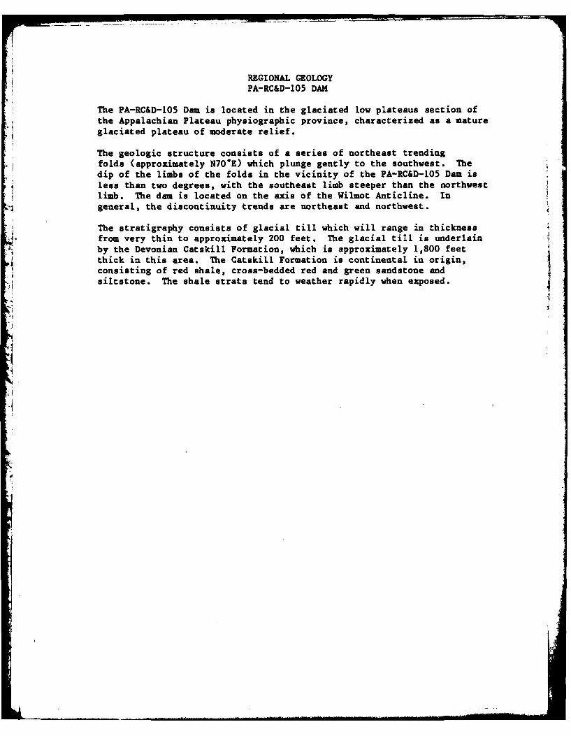
The PA-RC&D-105 Dam is located in the glaciated low plateaus section ofthe Appalachian Plateau physiographic province, characterized as a matureglaciated plateau of moderate relief.
The geologic structure consists of a series of northeast trendingfolds (approximately N70"E) which plunge gently to the southwest. Thedip of the limbs of the folds in the vicinity of the PA-RC&D-105 Dam isless than two degrees, with the southeast limb steeper than the northwest
*limb. The dam is located on the axis of the Wilmot Anticline. Ingeneral, the discontinuity trends are northeast and northwest.
The stratigraphy consists of glacial till which will range in thickness, from very thin to approximately 200 feet. The glacial till is underlain
by the Devonian Catskill Formation, which is approximately 1,800 feetthick in this area. The Catskill Formation is continental in origin,consisting of red shale, cross-bedded red and green sandstone andsiltstone. The shale strata tend to weather rapidly when exposed.

LaeSoh. o
0 2, 4 O0
SCAL La25,00i* *1 U6CUL*.. SS SIH O. -POW PA LtSSOvO7
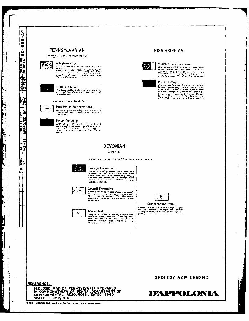
PENNSYLVANIAN MISSISSIPPIAN0APPALACHIAN PLATEAU
SAllegheny Group Mht Rar.Much C~hunk Foirmation
anoos. -'i. ih.roicmnrro .. .... on WI.'d tt"t.Wti'ci anid
,'~.o,,, "( ,,t I " I" . u" - ' .I."h.mot,. ra .
Pottsville Group 10,1,Pocon Gr..qouprt alaisinot
Pta itsi Gouplv anamta oecas~tet tron hndao 1Corohell ; = i 0ol. i. and- (h, pp .,ioi-i
m,.,able ittIV ad.0 inlAe .......flit pt A*,
ANTHRACITE REGION
A- Potfotsil Formationsia fita.~t -i -at nro, nit,,.
0DC able coalt..
P'ottsville Grouplih i ofi, t~a~ ,,i,~ otiad
.~ai c... gh.. i~ai 1:th ap ai
X ,~ih.ijll.l and( Tutingm R-n Foinr-
~XJ DEVONIANI UPPER
z CENTRAL AND EASTERN PENNSYLVANIA
a Oswayo FormationIraenish and greenish pray fine and-edian, fraisd sottdstane .4th .. me
!bare. an ... attered -a1-ar..... lenses;inld.red hsht w irIt ...ame m.re
numeros eaxtaord. Relatian to type0-P.n -at pro..ed.
Catskill FormationriChiefly ed ta Itratonish chale. and sand-.s........... tone., includes gray and greenish aind-stin, toge amed Elk Mountain,
in the east.
Susquehanna GroupBarbed line is Chmn.Catskill ta.-tact of Secand ~ienna1 4iini Surren
D, Marine heds County reports; barbs on 'Cheinung" sidsGray to liu- hroa ales,pmnaea. Jlneantd acndsonea cotisCheMIa bidsand 1-Mi,,ra bed. including Htarket.Brallier Haorrell, and Trimmers Rock;Tlly Ilaientane at bose.
GEOLOGY MAP LEGEND-FERENCEe
GEOLOGIC MAP OF PENNSYLVANIA PREPAREDBY COMMONWEALTH OF PENNA., DEPARTMENT OFENVIRONMENTAL RESOURCES , DATED: 1960 0A 2 O A NSCALE 1 :250,000
It 139 USACUL6111. A&S 6041TH CO.. POW . PA LT153O.107S

IA