adaa_concept report (low res)
TRANSCRIPT

INDEX
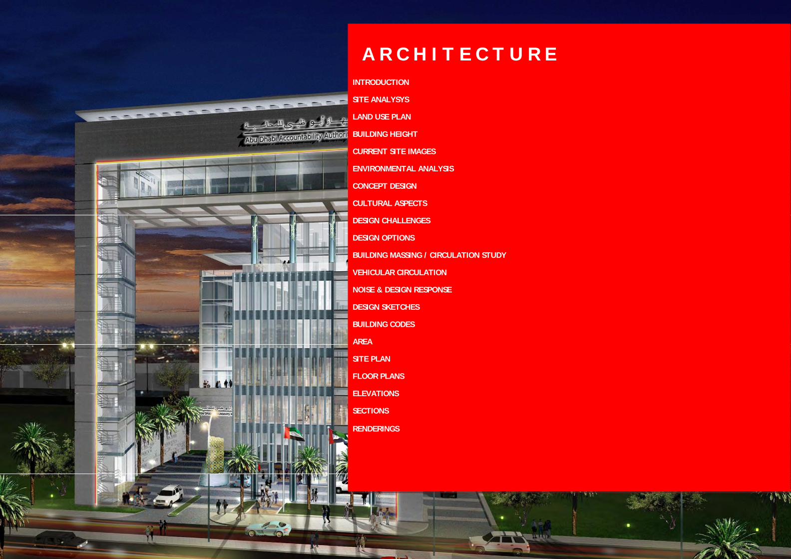
A R C H I T E C T U R E
S T R U C T U R E
M E C H A N I C A L E L E C T R I C A L P L U M B I N G
S U S T A I N A B I L I T Y
I N T E R I O R D E S I G N
L A N D S C A P E
A R C H I T E C T U R E 1
INTRODUCTION
SITE ANALYSYS
LAND USE PLAN
BUILDING HEIGHT
CURRENT SITE IMAGES
ENVIRONMENTAL ANALYSIS
CONCEPT DESIGN
CULTURAL ASPECTS
DESIGN CHALLENGES
DESIGN OPTIONS
BUILDING MASSING / CIRCULATION STUDY
VEHICULAR CIRCULATION
NOISE & DESIGN RESPONSE
DESIGN SKETCHES
BUILDING CODES
AREA
SITE PLAN
FLOOR PLANS
ELEVATIONS
SECTIONS
RENDERINGS
A R C H I T E C T U R E
A R C H I T E C T U R E 2
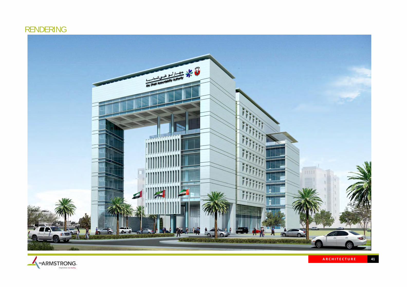
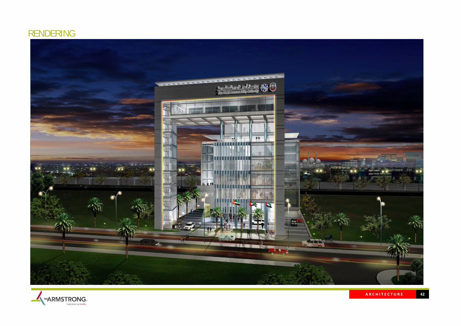
INTRODUCTION The new Abu Dhabi Accountability headquarters will be located on a site that offers views of downtown to the south and the surrounding governmental and business district in addition to the limited opportunity of the site, the building restrictions, regional environmental conditions and response to traditional presents are the primary factors informing the design.
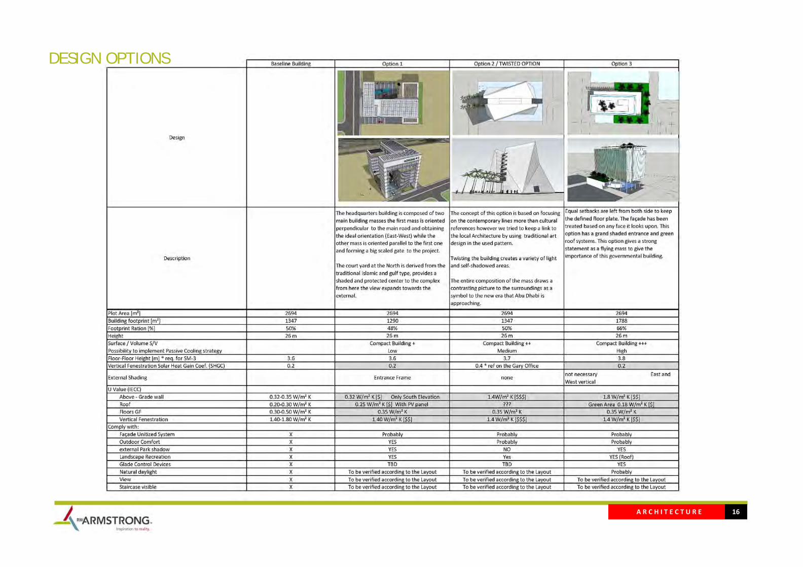
The headquarters building is composed of two main building masses the first mass is oriented perpendicular to the main road and obtaining the ideal orientation (East‐West) while the other mass is oriented parallel to the first one and forming a big scaled gate to the project.
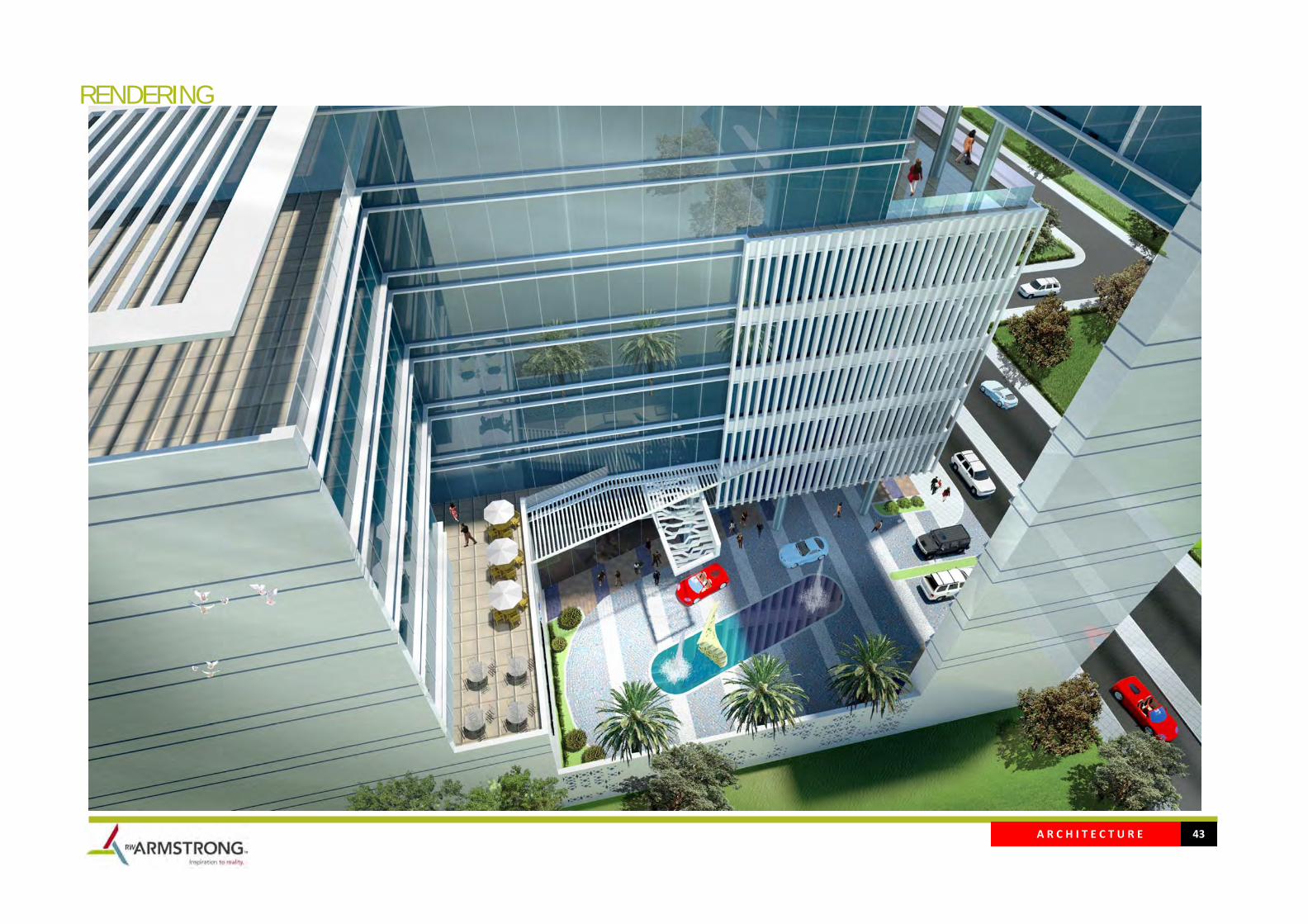
The court yard at the North is derived from the traditional Islamic and gulf type, provides a shaded and protected center to the complex from here the view expands towards the external.
While maximizing views, the exterior facades are also designed to respond to climatic conditions. The Western, Southern and Eastern exposures incorporate both horizontal screens and deep ribbon windows to reduce glare and heat gain. Transoms above the screens have tinted glazing for additional solar protection. The response to the solar condition, together with variation in curtain wall treatment add a layer of detail and scale to the compact building mass. Metal structures shade the roof and provide a support to the photo voltage panels that will help using the facades.
A R C H I T E C T U R E 3
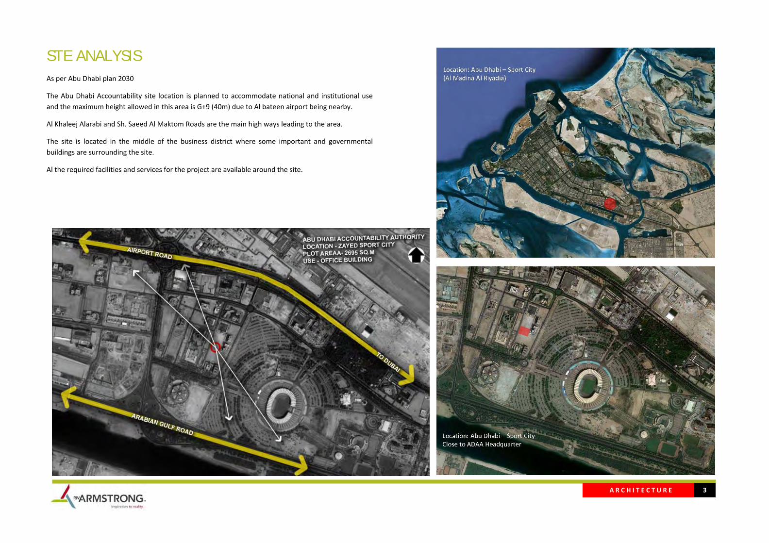
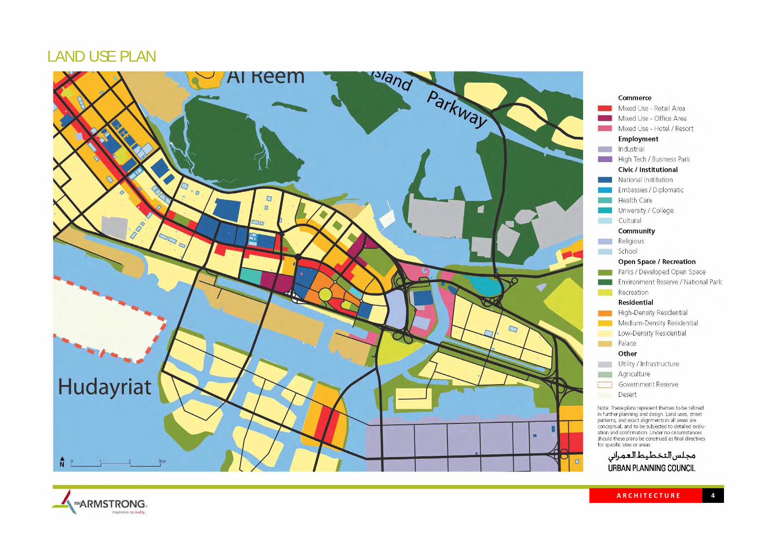
STE ANALYSIS As per Abu Dhabi plan 2030
The Abu Dhabi Accountability site location is planned to accommodate national and institutional use and the maximum height allowed in this area is G+9 (40m) due to Al bateen airport being nearby.
Al Khaleej Alarabi and Sh. Saeed Al Maktom Roads are the main high ways leading to the area.
The site is located in the middle of the business district where some important and governmental buildings are surrounding the site.
Al the required facilities and services for the project are available around the site.
A R C H I T E C T U R E 4
LAND USE PLAN

A R C H I T E C T U R E 5
BUILDING HEIGHT
A R C H I T E C T U R E 6
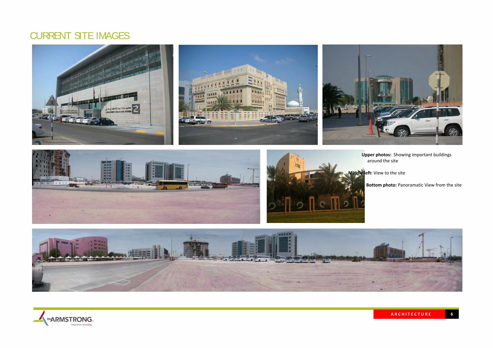
CURRENT SITE IMAGES
Upper photos: Showing important buildings around the site Middle left: View to the site Bottom photo: Panoramatic View from the site
A R C H I T E C T U R E 7
ENVIRONMENTAL ANALYSIS
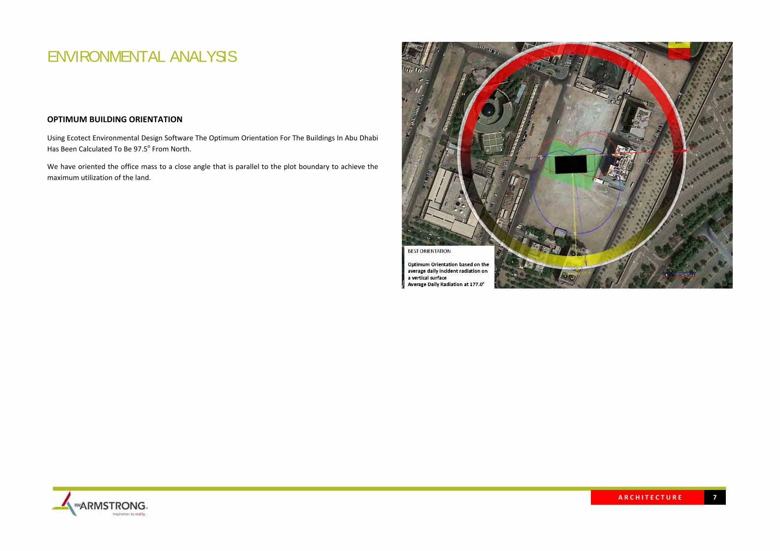
OPTIMUM BUILDING ORIENTATION
Using Ecotect Environmental Design Software The Optimum Orientation For The Buildings In Abu Dhabi Has Been Calculated To Be 97.5o From North.
We have oriented the office mass to a close angle that is parallel to the plot boundary to achieve the maximum utilization of the land.

A R C H I T E C T U R E 8
SITE ORIENTATION / WIND STUDY
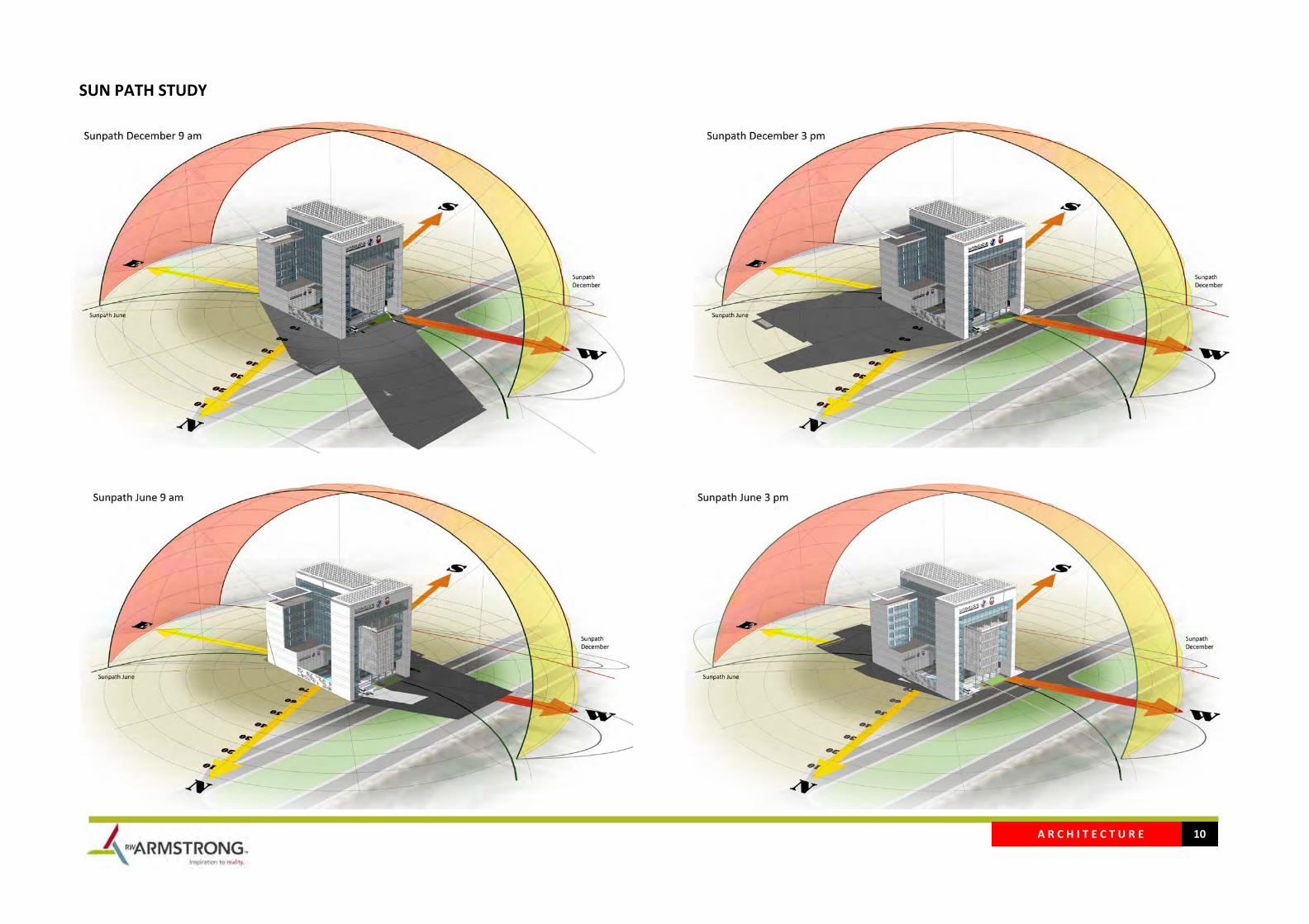
Overlaying the climatic data onto the site shows the seasonal sun path as well as prevailing wind directions.
The high sun angles in summer can be efficiently blocked by horizontal shading devices, however lower sun angles at the east/west facades have to be mitigated with deeper shades.
The alternating wind direction is beneficial in designing the openings the favorable cool wind in summer, while blocking it in winter.
Simulating the movement of prevailing wind around the building’s mass, the court yard and the gate void will be utilizing designing natural ventilation strategies, to cool the building during appropriate summer months hence reducing the requirement for mechanical ventilation.
A R C H I T E C T U R E 9
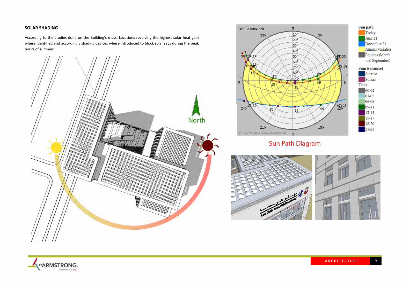
SOLAR SHADING
According to the studies done on the Building’s mass, Locations receiving the highest solar heat gain where identified and accordingly shading devices where introduced to block solar rays during the peak hours of summer,
A R C H I T E C T U R E 10
SUN PATH STUDY

A R C H I T E C T U R E 11
CONCEPT DESIGN Because of the function of the project as an important authority one of few that handles the monitoring of the accountability of other governmental authority and departments of Abu Dhabi, the transparency, clarity and this transparency was reflected in the overall design of this project
Using strong straight lines, curtain walls and white cladded walls that reflect the transparency that the function of the authority acts upon.
Culture
This building is considered as a new landmark which expresses the culture of UAE in general; The concept of this project come to emphasize on the future and to record this moment of change through the relationship between the old and the new, through the relationship between the traditional culture and the new emerging culture through the relationship between the past and the emerging future of Abu Dhabi.
The project is intended to be integrated within the local culture of UAE. Studying the different elements of the Libyan culture, the project has been inspired by the following elements:
A R C H I T E C T U R E 12
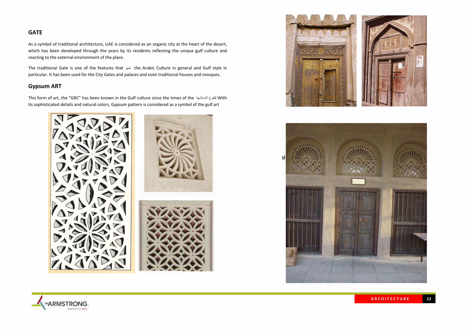
GATE
As a symbol of traditional architecture, UAE is considered as an organic city at the heart of the desert, which has been developed through the years by its residents reflecting the unique gulf culture and reacting to the external environment of the place.
The traditional Gate is one of the features that تميز the Arabic Culture in general and Gulf style in particular. It has been used for the City Gates and palaces and even traditional houses and mosques.
Gypsum ART
This form of art, the “GRC” has been known in the Gulf culture since the times of the االسالمية فتوحال With its sophisticated details and natural colors, Gypsum pattern is considered as a symbol of the gulf art
A R C H I T E C T U R E 13
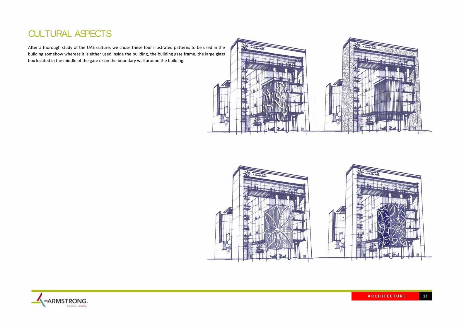
CULTURAL ASPECTS After a thorough study of the UAE culture; we chose these four illustrated patterns to be used in the building somehow whereas it is either used inside the building, the building gate frame, the large glass box located in the middle of the gate or on the boundary wall around the building.
A R C H I T E C T U R E 14
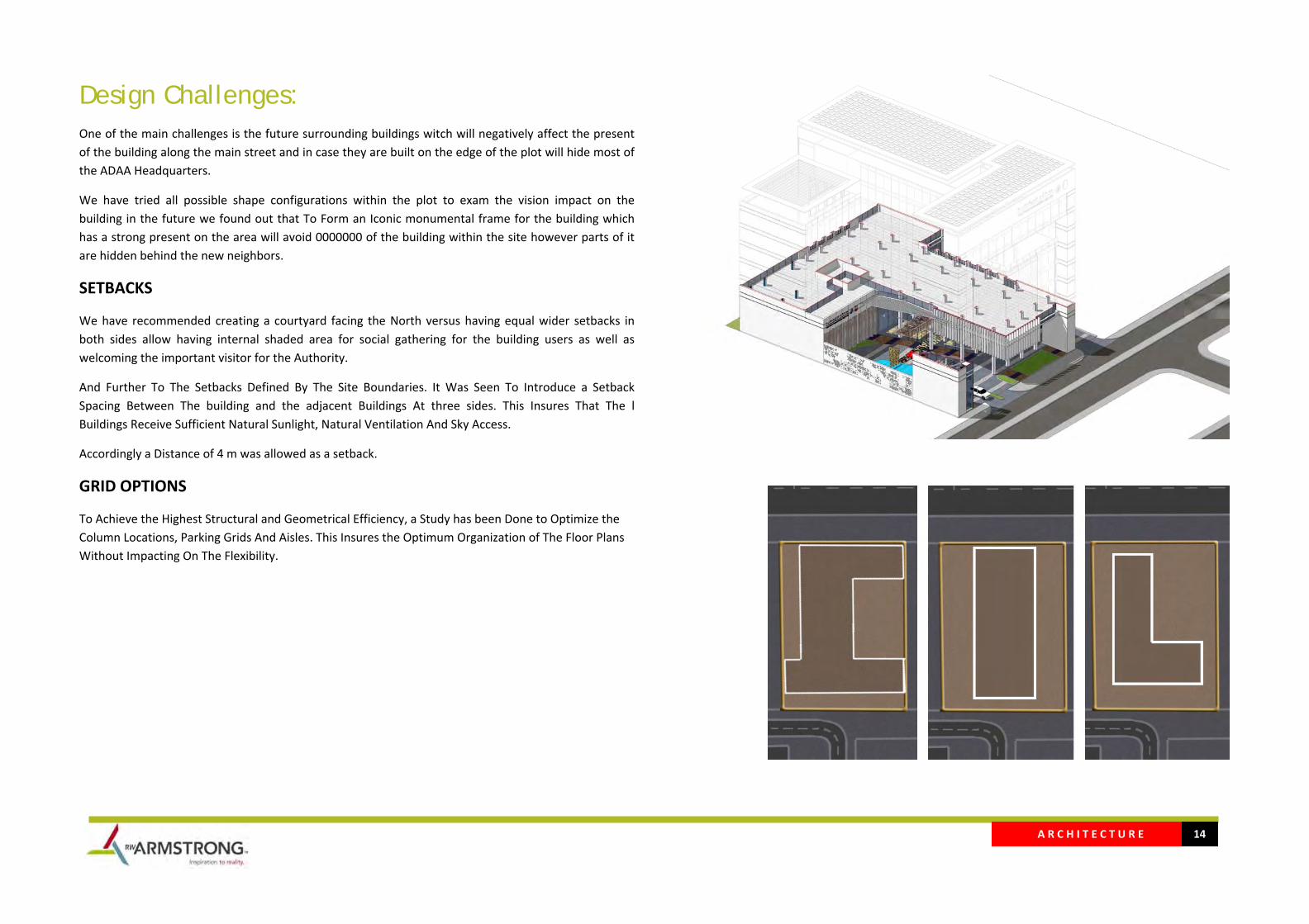
Design Challenges: One of the main challenges is the future surrounding buildings witch will negatively affect the present of the building along the main street and in case they are built on the edge of the plot will hide most of the ADAA Headquarters.
We have tried all possible shape configurations within the plot to exam the vision impact on the building in the future we found out that To Form an Iconic monumental frame for the building which has a strong present on the area will avoid 0000000 of the building within the site however parts of it are hidden behind the new neighbors.
SETBACKS
We have recommended creating a courtyard facing the North versus having equal wider setbacks in both sides allow having internal shaded area for social gathering for the building users as well as welcoming the important visitor for the Authority.
And Further To The Setbacks Defined By The Site Boundaries. It Was Seen To Introduce a Setback Spacing Between The building and the adjacent Buildings At three sides. This Insures That The l Buildings Receive Sufficient Natural Sunlight, Natural Ventilation And Sky Access.
Accordingly a Distance of 4 m was allowed as a setback.
GRID OPTIONS
To Achieve the Highest Structural and Geometrical Efficiency, a Study has been Done to Optimize the Column Locations, Parking Grids And Aisles. This Insures the Optimum Organization of The Floor Plans Without Impacting On The Flexibility.
A R C H I T E C T U R E 15
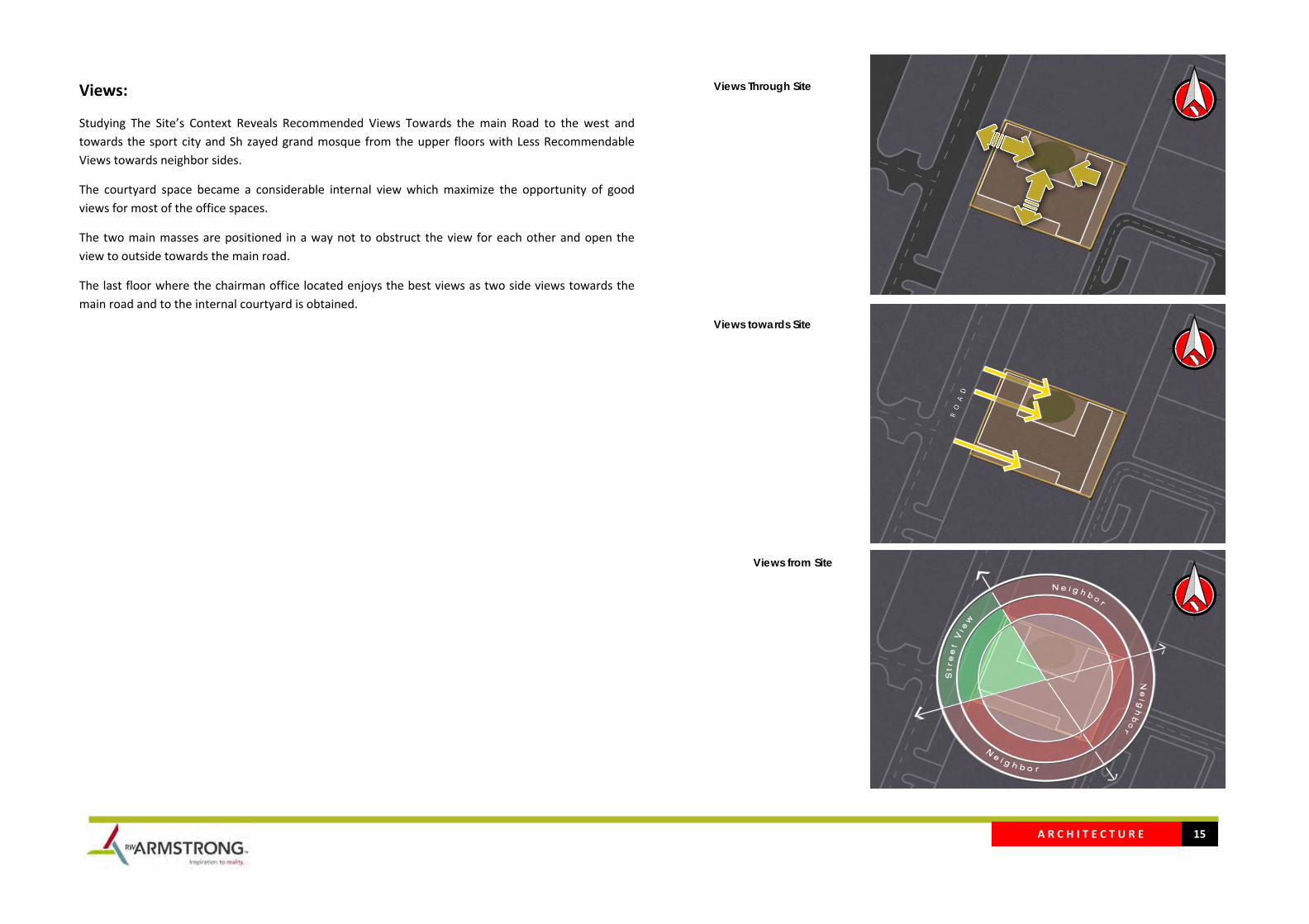
Views:
Studying The Site’s Context Reveals Recommended Views Towards the main Road to the west and towards the sport city and Sh zayed grand mosque from the upper floors with Less Recommendable Views towards neighbor sides.
The courtyard space became a considerable internal view which maximize the opportunity of good views for most of the office spaces.
The two main masses are positioned in a way not to obstruct the view for each other and open the view to outside towards the main road.
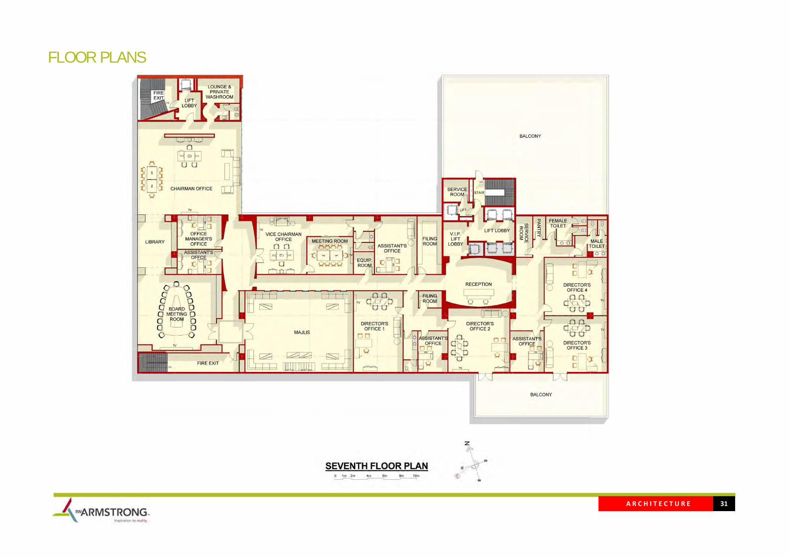
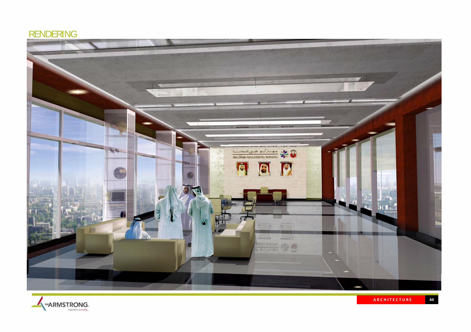
The last floor where the chairman office located enjoys the best views as two side views towards the main road and to the internal courtyard is obtained.
Views Through Site
Views towards Site
Views from Site
A R C H I T E C T U R E 16
DESIGN OPTIONS
A R C H I T E C T U R E 17
BUILDING MASSING / CIRCULATION STUDY

A R C H I T E C T U R E 18
VEHICULAR CIRCULATION
A R C H I T E C T U R E 19
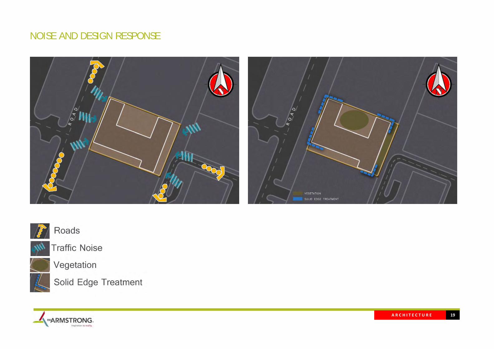
NOISE AND DESIGN RESPONSE

A R C H I T E C T U R E 20
DESIGN SKETCHES The initial thought was to create a statement that presents the governmental Importance. Examining different type of shapes that give this effect meanwhile have the best site utilization, constructability and efficient and confortable office spaces.
A R C H I T E C T U R E 21
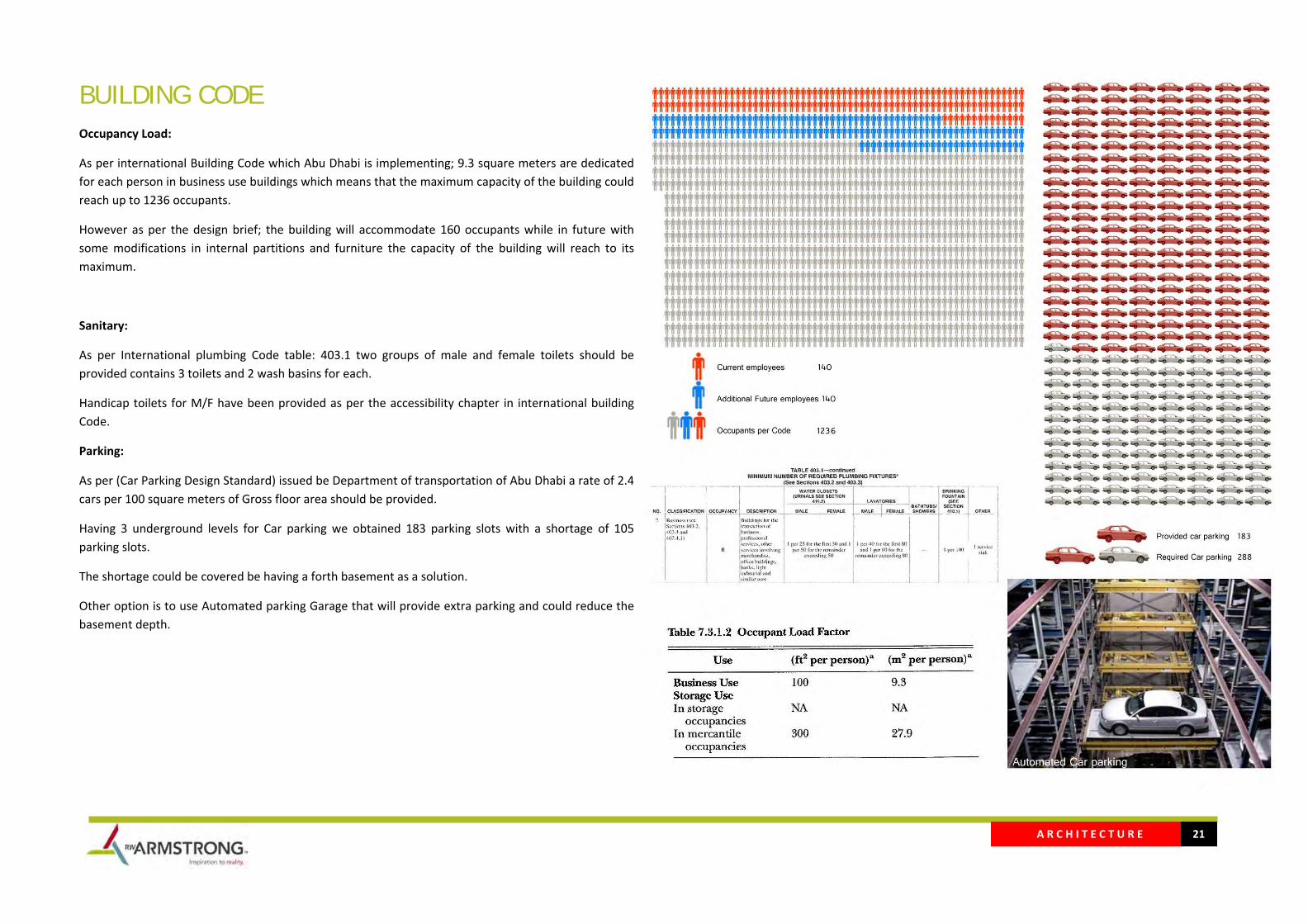
BUILDING CODE Occupancy Load:
As per international Building Code which Abu Dhabi is implementing; 9.3 square meters are dedicated for each person in business use buildings which means that the maximum capacity of the building could reach up to 1236 occupants.
However as per the design brief; the building will accommodate 160 occupants while in future with some modifications in internal partitions and furniture the capacity of the building will reach to its maximum.
Sanitary:
As per International plumbing Code table: 403.1 two groups of male and female toilets should be provided contains 3 toilets and 2 wash basins for each.
Handicap toilets for M/F have been provided as per the accessibility chapter in international building Code.
Parking:
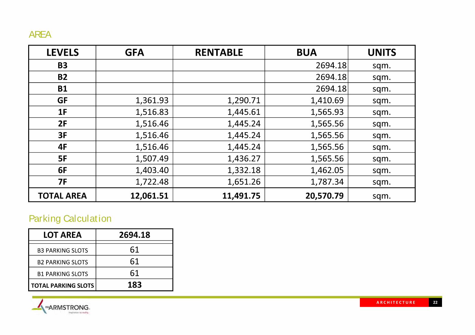
As per (Car Parking Design Standard) issued be Department of transportation of Abu Dhabi a rate of 2.4 cars per 100 square meters of Gross floor area should be provided.
Having 3 underground levels for Car parking we obtained 183 parking slots with a shortage of 105 parking slots.
The shortage could be covered be having a forth basement as a solution.
Other option is to use Automated parking Garage that will provide extra parking and could reduce the basement depth.
A R C H I T E C T U R E 22
AREA
Parking Calculation
A R C H I T E C T U R E 23
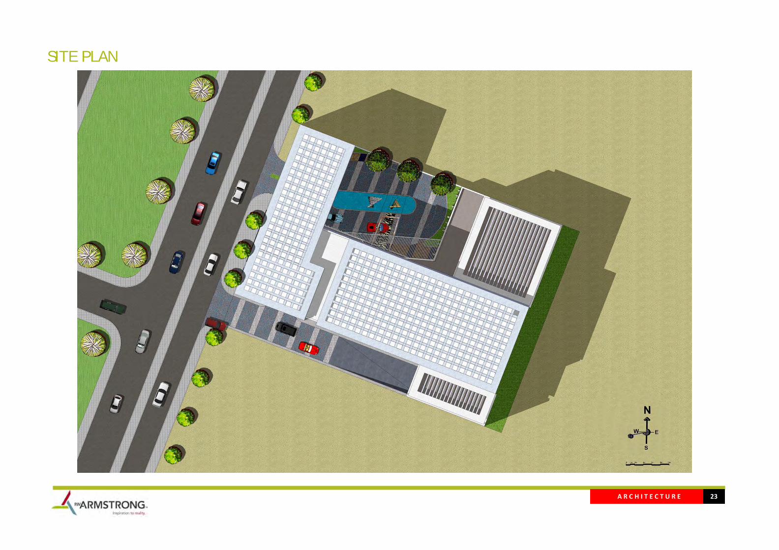
SITE PLAN

A R C H I T E C T U R E 24
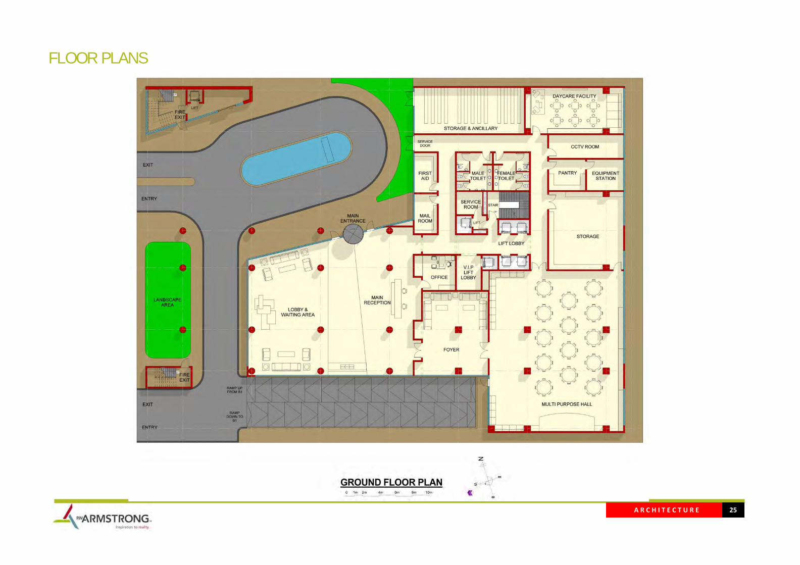
FLOOR PLANS
A R C H I T E C T U R E 25
FLOOR PLANS
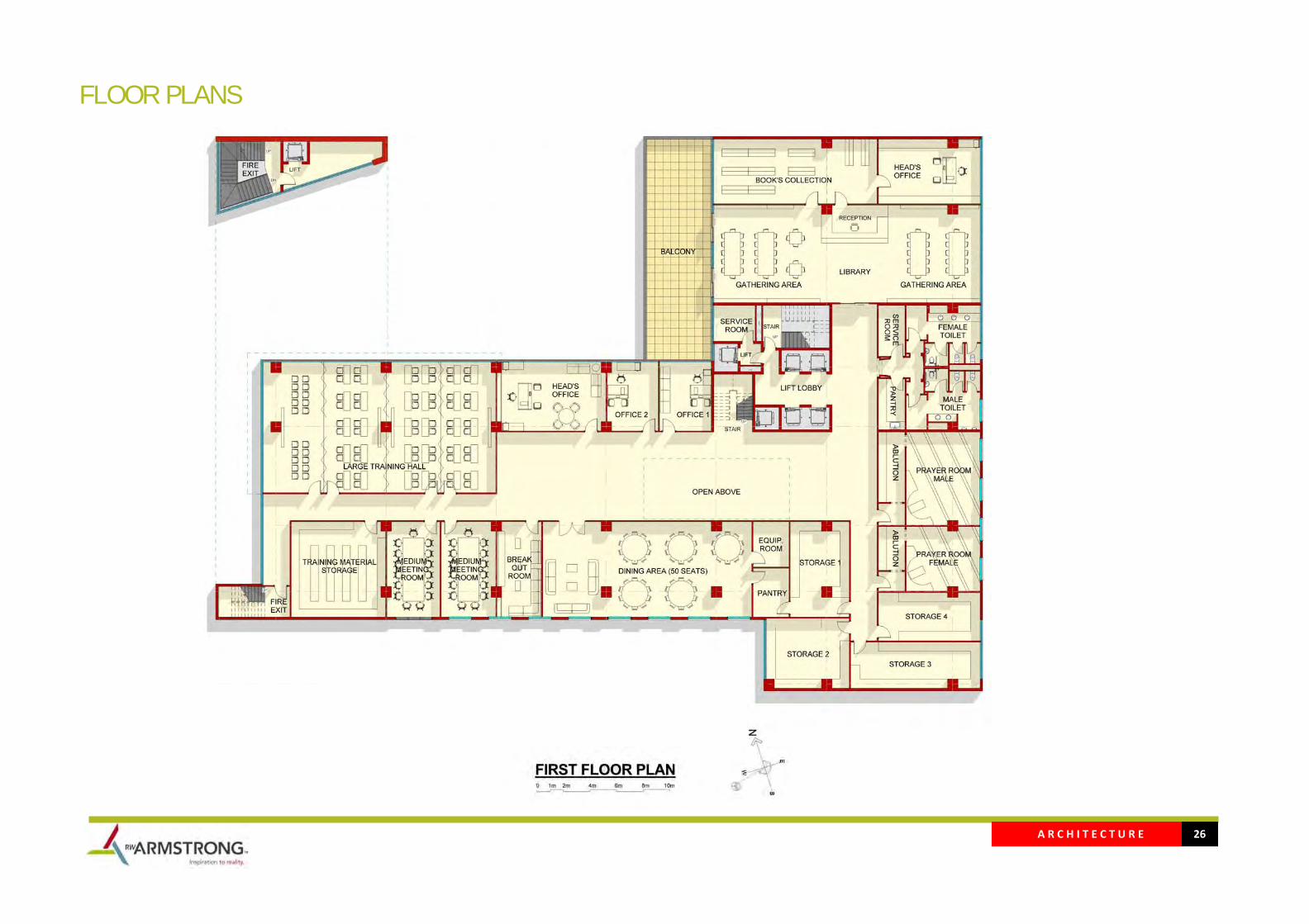
A R C H I T E C T U R E 26
FLOOR PLANS
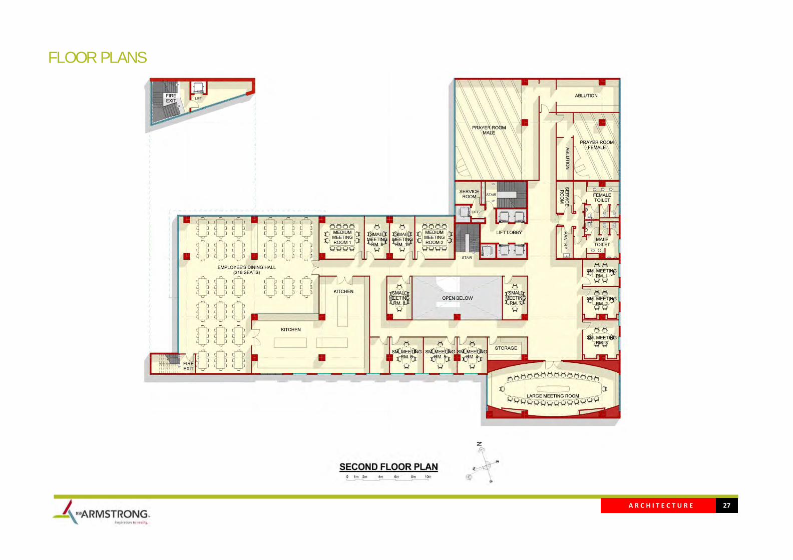
A R C H I T E C T U R E 27
FLOOR PLANS

A R C H I T E C T U R E 28
FLOOR PLANS
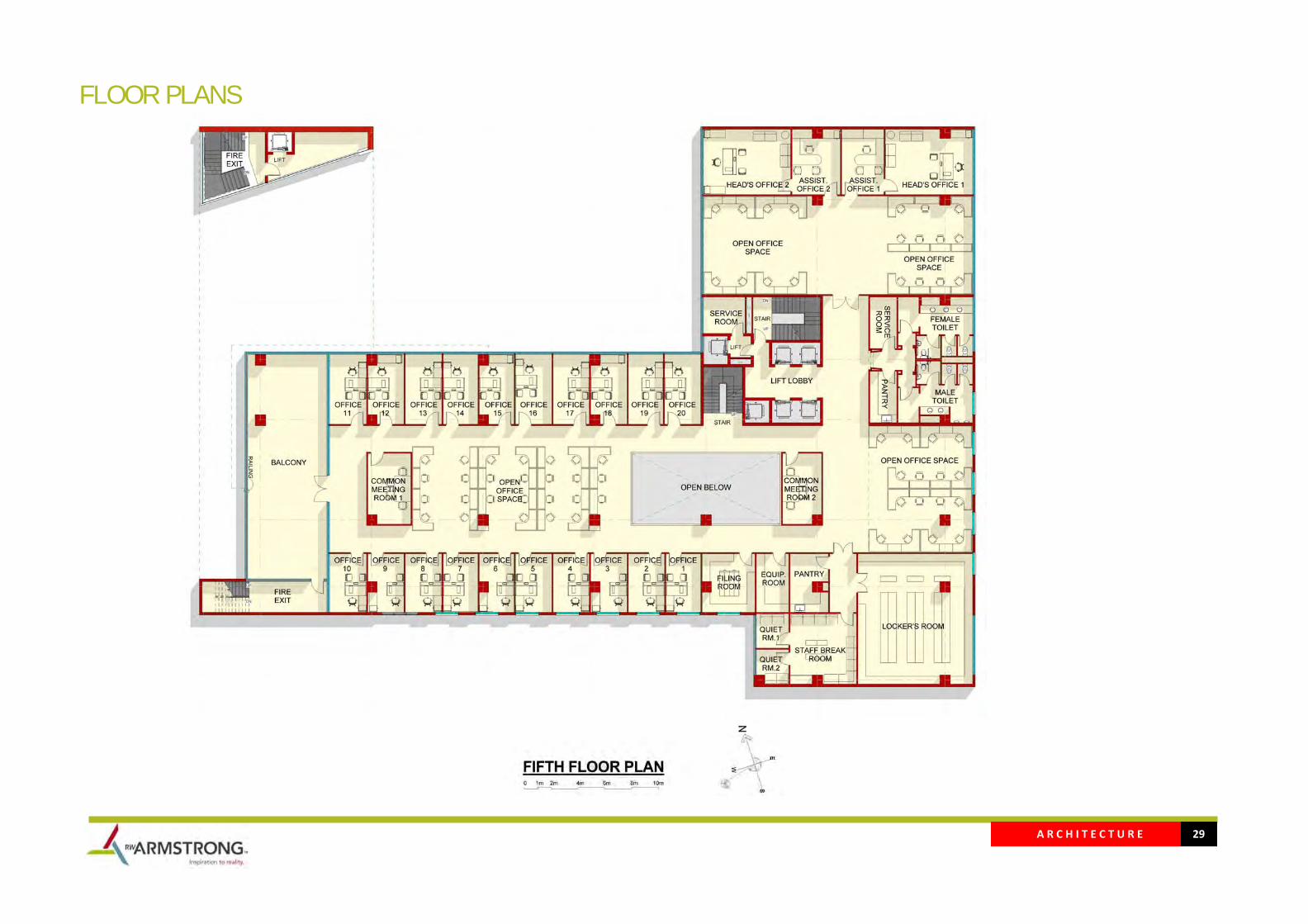
A R C H I T E C T U R E 29
FLOOR PLANS
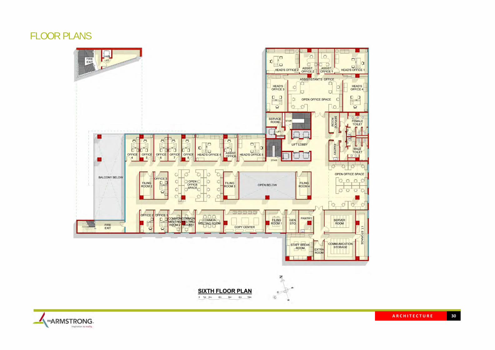
A R C H I T E C T U R E 30
FLOOR PLANS
A R C H I T E C T U R E 31
FLOOR PLANS

A R C H I T E C T U R E 32
FRONT ELEVATION
A R C H I T E C T U R E 33
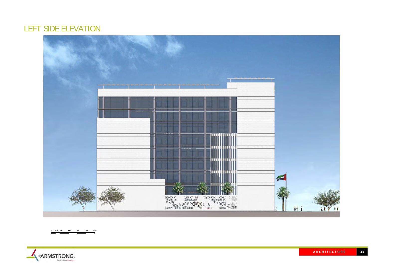
LEFT SIDE ELEVATION
A R C H I T E C T U R E 34
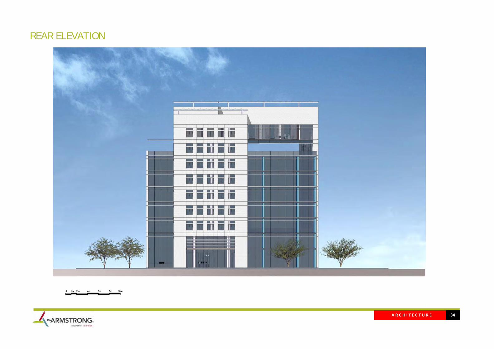
REAR ELEVATION
A R C H I T E C T U R E 35
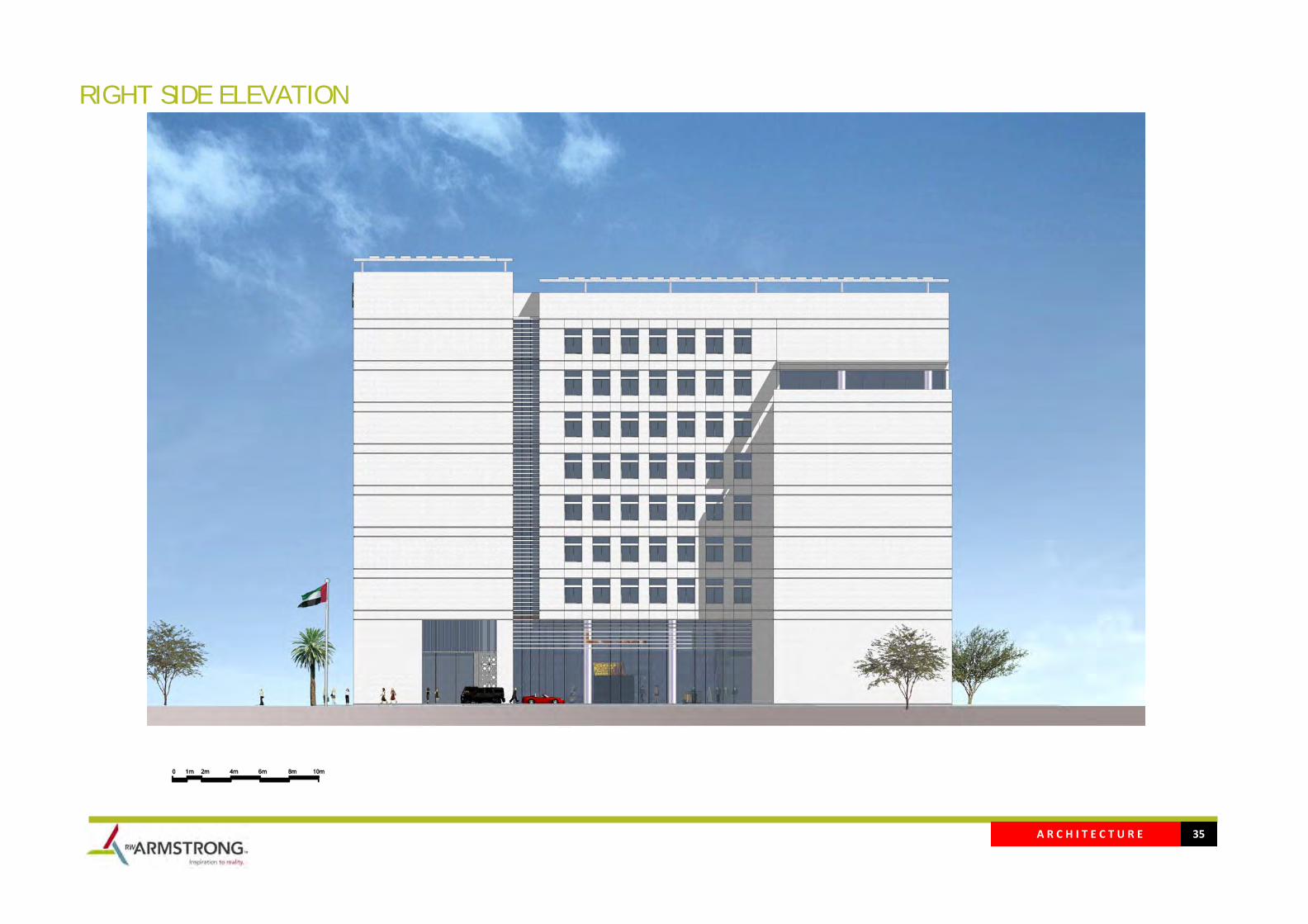
RIGHT SIDE ELEVATION
A R C H I T E C T U R E 36
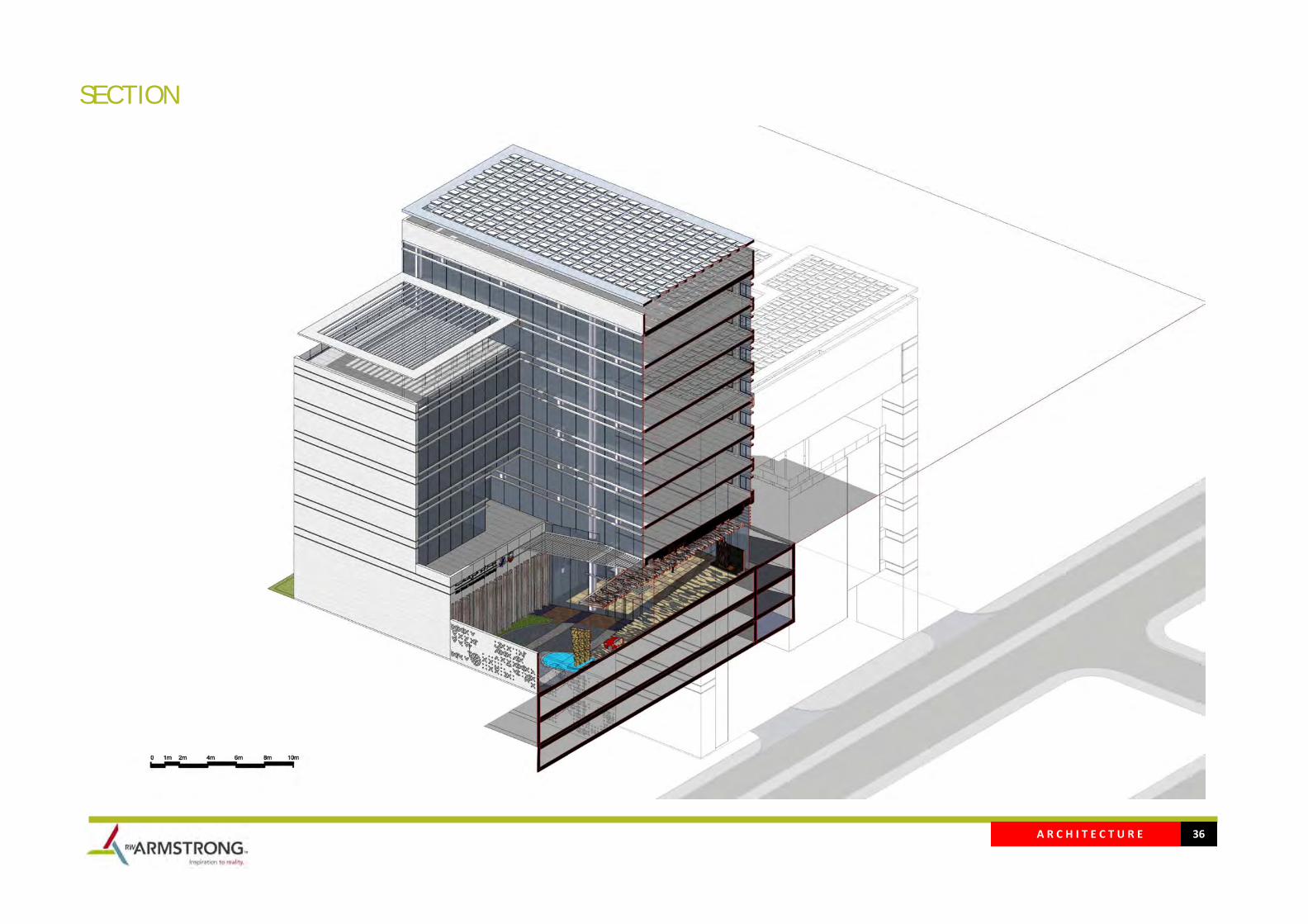
SECTION
A R C H I T E C T U R E 37
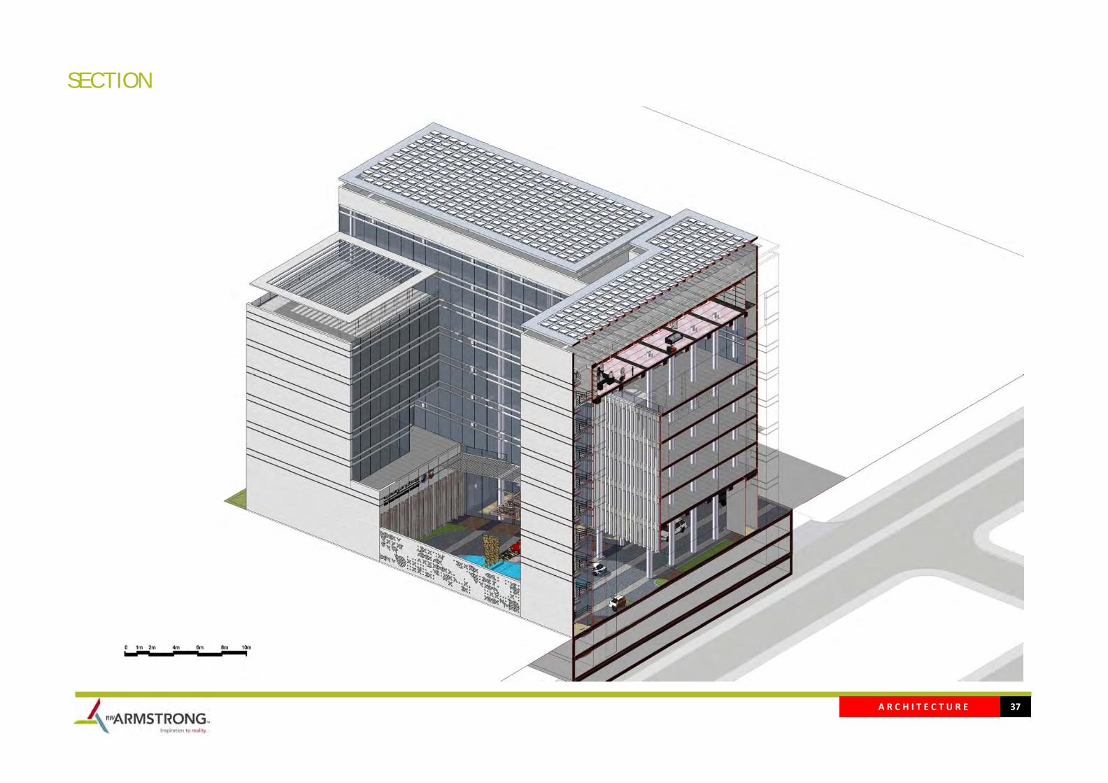
SECTION
A R C H I T E C T U R E 38
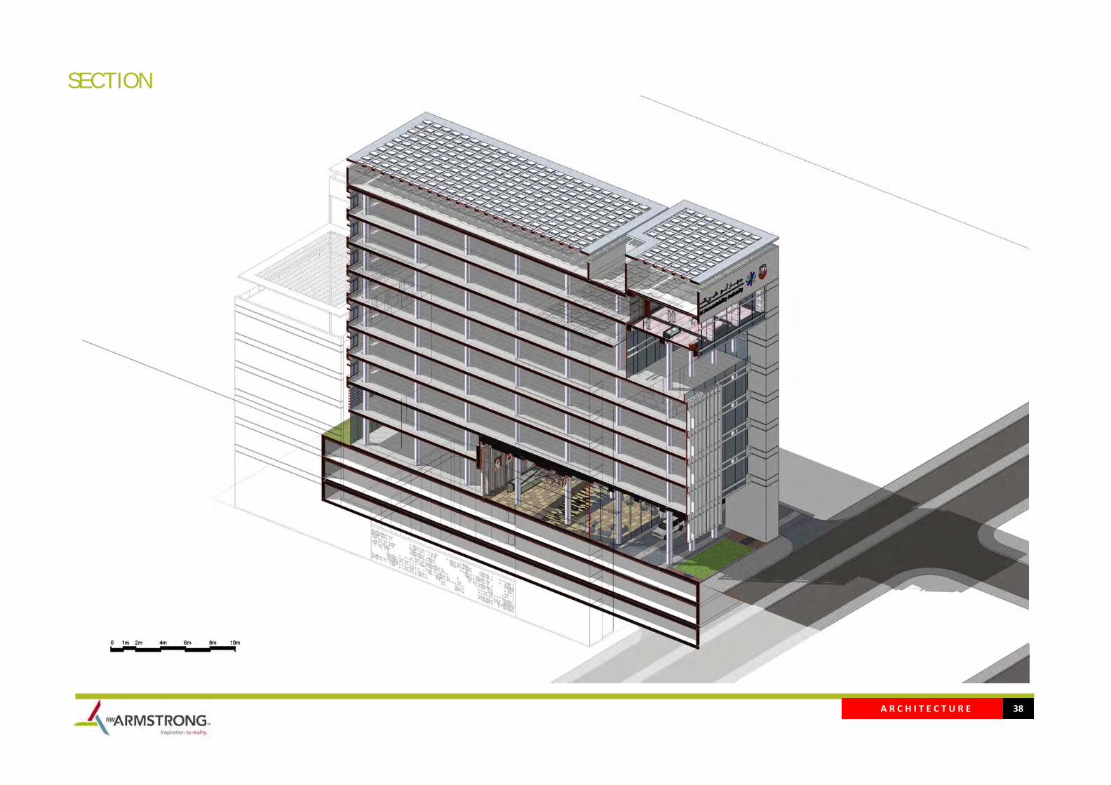
SECTION

A R C H I T E C T U R E 39
SECTION
A R C H I T E C T U R E 40
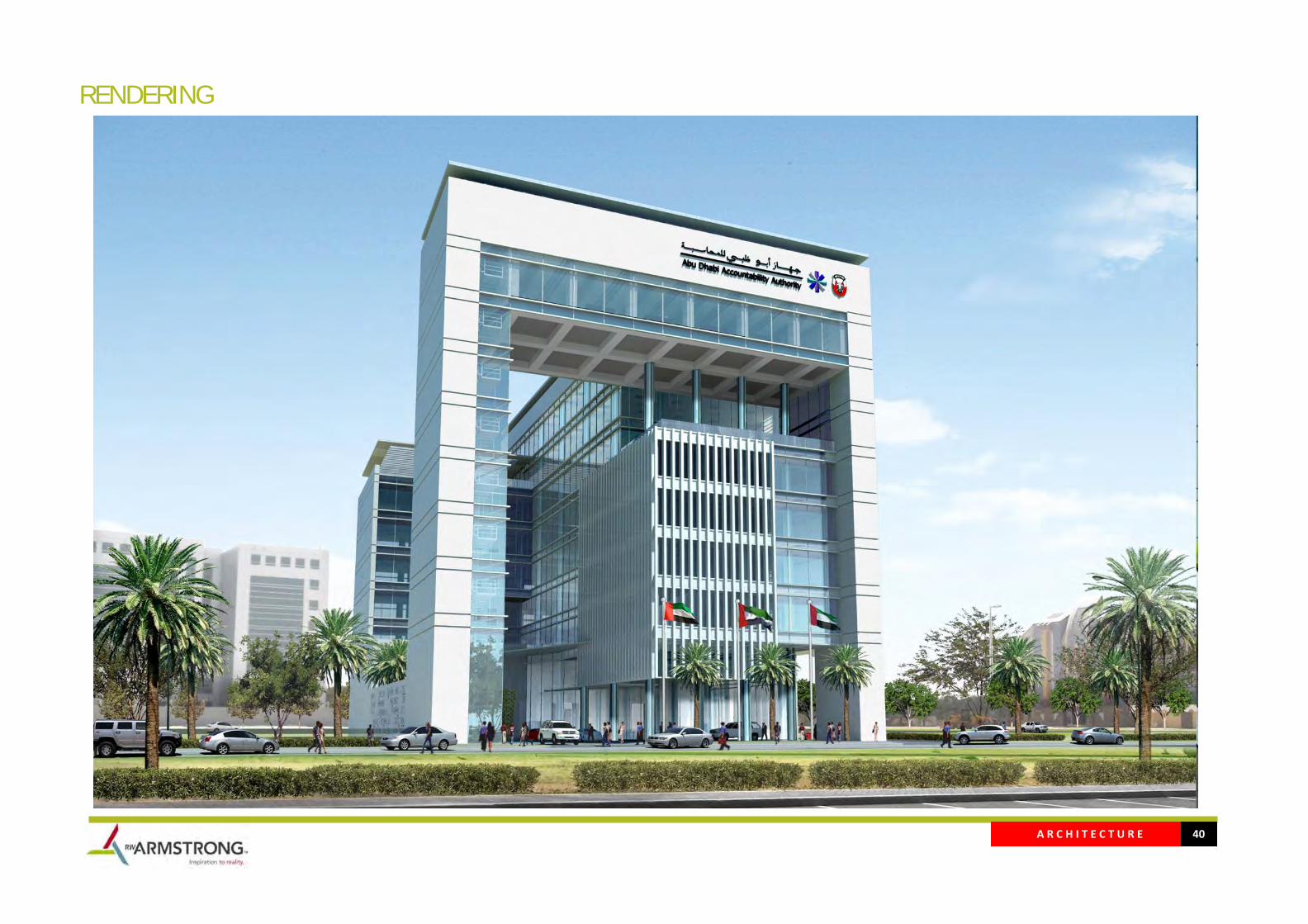
RENDERING
A R C H I T E C T U R E 41
RENDERING
A R C H I T E C T U R E 42
RENDERING
A R C H I T E C T U R E 43
RENDERING
A R C H I T E C T U R E 44
RENDERING

1
S T R U C T U R E
S T R U C T U R E
1 GENERAL
2 MATERIALS
2.1 Reinforced Concrete
2.2 Precast – Prestressed Concrete
3 DURABILITY
4 DESIGN PHILOSOPHY
4.1 FOUNDATIONS
4.2 SUPER STRUCTURE SYSTEM DESCRIPTION
4.3 ADVANTAGES OF THE PROPOSED SYSTEM

2
S T R U C T U R E
1 GENERAL This volume summarizes the construction methodology for the Abu Dhabi Accountability Authority Head Quarters. The parameters have been established as being the most appropriate for the Project, where the proposed structural system accommodates the building functions, its architectural design and the building service requirements.
2 MATERIALS
The choice of construction material in Abu Dhabi is affected by many factors specific to the region. The following list identifies the most significant of these:
• High temperatures, which can exceed 45 Celsius at peak times. • Airborne salt contamination due to the coastal location and high humilities. • Large temperature ranges from day and night and seasonally, these can have significant
effect on the thermal movements of material such as concrete and hence the requirement for regular spaced movement joints.
• High evaporation rates due to the high temperatures; this can cause in‐situ concrete to dry quickly causing damaging thermal shrinkage.
• Availability of local sources of raw materials
The above mentioned factors are considered in the selection of construction material along the structural advantages and disadvantages of different options, where in all cases great care must be taken to ensure the structural integrity.
2.1 Reinforced Concrete
Reinforced concrete is the most common indigenous and locally available structural construction material. Concrete’s versatility, durability and economy have made it the world’s most used construction material. It is used in buildings, high‐rise, dams, homes, floors and numerous other applications. Concrete is strong in compression, but weak in tension, thus adding reinforcement increases the strength in tension. In addition, the failure strain of concrete in tension is so low that the reinforcement has to hold the cracked sections together.
For a strong, ductile and durable construction the reinforcement shall have the following properties:
• High strength • High tensile strain • Good bond to the concrete • Thermal compatibility • Durability in the concrete environment
Reinforced concrete can encompass many types of structures and components, including slabs, walls, beams, columns, foundations, frames and more. Much of the focus on reinforcing concrete is placed on floor systems. Designing and implementing the most efficient floor system is key to creating optimal building structures. Small changes in the design of a floor system can have significant impact on material costs, construction schedule, and ultimate strength, operating costs, occupancy levels and end use of a building.
Figure 2.1 Reinforced Concrete Constructions.
3
S T R U C T U R E
The advantages of using reinforced concrete are:
• Local contractors and their tradesmen are experienced in reinforced concrete construction;
• The reinforced concrete trade is well established in the Emirates; • The building materials used are available locally; • Total flexibility in space planning; • Better resistance to environment attack from salt‐laden water; • Concrete has increased resistance to explosion and/or impact; • Concrete resists very high temperatures from fire for a long time without loss of
structural integrity; • Concrete inherent mass and strength provides resistance to lateral forces; • Concrete seeks the form – any shape can be achieved; • Concrete has flexibility to accommodate design changes later in the progress; • The inherent mass of concrete provides benefits in terms of acoustics and
vibration criteria of the building.
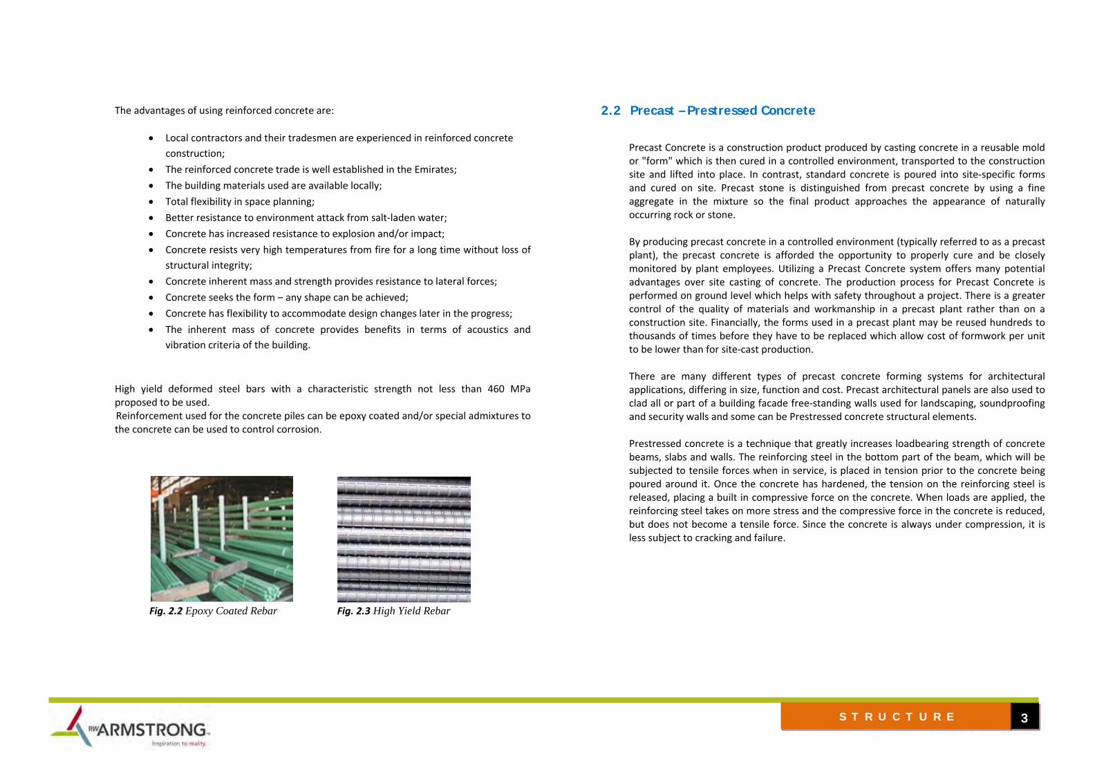
High yield deformed steel bars with a characteristic strength not less than 460 MPa proposed to be used. Reinforcement used for the concrete piles can be epoxy coated and/or special admixtures to the concrete can be used to control corrosion.
Fig. 2.2 Epoxy Coated Rebar Fig. 2.3 High Yield Rebar
2.2 Precast – Prestressed Concrete
Precast Concrete is a construction product produced by casting concrete in a reusable mold or "form" which is then cured in a controlled environment, transported to the construction site and lifted into place. In contrast, standard concrete is poured into site‐specific forms and cured on site. Precast stone is distinguished from precast concrete by using a fine aggregate in the mixture so the final product approaches the appearance of naturally occurring rock or stone. By producing precast concrete in a controlled environment (typically referred to as a precast plant), the precast concrete is afforded the opportunity to properly cure and be closely monitored by plant employees. Utilizing a Precast Concrete system offers many potential advantages over site casting of concrete. The production process for Precast Concrete is performed on ground level which helps with safety throughout a project. There is a greater control of the quality of materials and workmanship in a precast plant rather than on a construction site. Financially, the forms used in a precast plant may be reused hundreds to thousands of times before they have to be replaced which allow cost of formwork per unit to be lower than for site‐cast production. There are many different types of precast concrete forming systems for architectural applications, differing in size, function and cost. Precast architectural panels are also used to clad all or part of a building facade free‐standing walls used for landscaping, soundproofing and security walls and some can be Prestressed concrete structural elements. Prestressed concrete is a technique that greatly increases loadbearing strength of concrete beams, slabs and walls. The reinforcing steel in the bottom part of the beam, which will be subjected to tensile forces when in service, is placed in tension prior to the concrete being poured around it. Once the concrete has hardened, the tension on the reinforcing steel is released, placing a built in compressive force on the concrete. When loads are applied, the reinforcing steel takes on more stress and the compressive force in the concrete is reduced, but does not become a tensile force. Since the concrete is always under compression, it is less subject to cracking and failure.

4
S T R U C T U R E
Figure 2.4 Precast construction
3 DURABILITY
Concrete structures shall be designed to resist attack from the following environmental conditions:
1. Sulphates and chlorides in the subsoil. 2. Sulphates and chlorides in ground water. 3. Wind‐blown salts including aerosols. 4. The aggressive climate, including marine conditions. 5. Availability of suitable water for mixing and curing concrete. 6. Possible contamination by Sulphates and chlorides in aggregates.
4 DESIGN PHILOSOPHY
Generally, the design philosophy for the structure is as follows:
• Gravity loads will be transferred from the floor plates to vertical elements like columns and walls, lateral loads will be transferred through floor diaphragm to the lateral loads resisting
system of shear walls and / or rigid columns. Scheme framing diagrams is shown in figure 2.5.
• Efficient transfer of loads from floors to foundation will be adopted consistent with the
architectural requirements.
• Maximization of materials and content of local origin will be a priority and will be taken into account in the design decision process relating to the structural media and form.
• Incorporation of local construction practices and methods and use of local materials, which
may give rise to savings, will be considered during the design process.
• High strength materials for concrete, reinforcing steel and structural steel will be used where possible within the constraints set by serviceability requirements. This results in greater efficiency of construction materials and a lower cost of construction.
Figure 2.5 Framing and Load Transfer Schematic Diagram.
5
S T R U C T U R E
4.1 FOUNDATIONS
Abu Dhabi is situated towards the eastern extremity of the geologically stable Arabian Plate and is separated from the unstable Iranian Fold Belt to the north by the Arabian Gulf. It is believed that a tilting of the entire Arabian Plate occurred during the early Permian period, resulting in uplift in southern Yemen and depression to the north east. Tectonic movement’s peripheral to folding of the Iranian Zagros Range during the Pilo‐Pleistocene epoch probably contributed to the formation of both the Arabian Gulf depression and the mountainous regions in the north east of the UAE and Oman. Of particular interest geologically and geotechnically is the presence of weakly cemented calcareous deposits, deposits of evaporates, mainly gypsum and potential cavities/vast features.
The foundation design will be based on the subsurface soil investigation interpretive report and recommendations of the geotechnical specialist. Foundation type will be further discussed during the Schematic Design phase upon soil investigation completion. A combination of high performance concrete and an external membrane system to achieve the necessary water proofing and durability will be used for the foundation. The use of a high performance concrete in the foundations and basement external envelope is essential to the design. The concrete mix needs to be dense and impermeable, to prevent the ingress of water, chlorides and sulphates into the concrete matrix to achieve the required level of durability. The concrete must also display low shrinkage and coefficient of expansion characteristics to achieve the joint‐less construction required by the design.
4.2 SUPER STRUCTURE SYSTEM DESCRIPTION
Abu Dhabi Accountability Authority Head Quarter comprises of 7 story plus two basement level structure with span requirements of approx. maximum of 9 meters and with approximate height clearance of 4 meters.
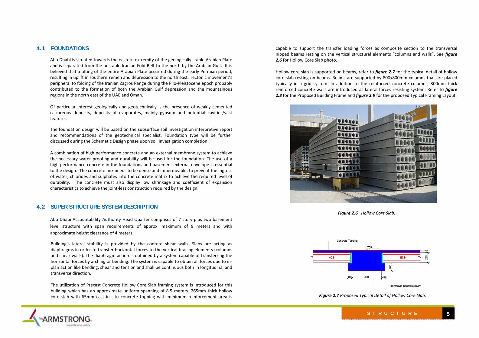
Building’s lateral stability is provided by the conrete shear walls. Slabs are acting as diaphragms in order to transfer horizontal forces to the vertical bracing elements (columns and shear walls). The diaphragm action is obtained by a system capable of transferring the horizontal forces by arching or bending. The system is capable to obtain all forces due to in‐plan action like bending, shear and tension and shall be continuous both in longitudinal and transverse direction. The utilization of Precast Concrete Hollow Core Slab framing system is introduced for this building which has an approximate uniform spanning of 8.5 meters. 265mm thick hollow core slab with 65mm cast in situ concrete topping with minimum reinforcement area is
capable to support the transfer loading forces as composite section to the transversal nipped beams resting on the vertical structural elements “columns and walls”. See figure 2.6 for Hollow Core Slab photo. Hollow core slab is supported on beams, refer to figure 2.7 for the typical detail of hollow core slab resting on beams. Beams are supported by 800x800mm columns that are placed typically in a grid system. In addition to the reinforced concrete columns, 300mm thick reinforced concrete walls are introduced as lateral forces resisting system. Refer to figure 2.8 for the Proposed Building Frame and figure 2.9 for the proposed Typical Framing Layout.
Figure 2.6 Hollow Core Slab.
Figure 2.7 Proposed Typical Detail of Hollow Core Slab.

6
S T R U C T U R E
Figure 2.8 Proposed Building Frame with Shear Wall Cast In‐Situ.
Figure 2.9 Proposed Typical Framing Layout.

7
S T R U C T U R E
4.3 ADVANTAGES OF THE PROPOSED SYSTEM The proposed system presented part traditional construction and part Off‐site construction. Advantages of traditional construction are discussed on section 2.1. This section will focused on the Off‐site Construction advantages, as follows:
• Speed of design (typically 30‐60% quicker design time) • Flexibility of design (ability to “plug & play”) • Concurrent production, whist enabling works are under way • Minimized site disruption, due to far less time on site compared to traditional
construction methods • Improved quality: controlled conditions not weather dependant • Flexibility, through future expansion & relocation • Far greater control over MEP, installation and design most of which is pre‐commissioned
under factory controlled conditions • Construction schedule, reduced construction time by up to 50% • Risk, increased predictability of project outcomes in terms of quality, cost and time • Quality, factory production methodology allows for the improvement of building
quantity • Procurement, increased ability for collaboration and single‐point of responsibility • Factory Time Efficiency, methods of production reduce construction tast time • Disturbance minimizes, disruptions to adjacent buildings and occupants and increase
cleanliness of building process • Technology, greater ability to manufacture components with high degree of technical
complexibility • Site, eliminates various site constraints such as staging, weather, transportation, etc. • Security, factory environment improves conditions for constructioin workers • Sustainability & Waste, improved project sustainability and viability of LEED ESTIMADA
rating • Relocability, possibility to move structure to new location • Economies of Scale, typical benefits of economy of scale are amplified for large projects
For Abu Dhabi Accountability Head Quarters two types of superstructure system can be adapted,
1. Hollow core slabs with Reinforced Concrete Framing. This system is a Hybrid Style Construction that comprises of traditional beams,columns and shear walls cast in‐situ construction and precast slabs construction.
Hollow core slabs are introduced for the floor system. Pre‐cast pre‐stressed concrete elements with continuous voids to reduce self‐weight and achieve structural efficiency are very popular and economic across a wide range of spans and loadings. The slabs are part of a full frame system and are capable to provide rigid floor diagphram in precast construction. Figure 2.10 Hollow Core Slab supported on Concrete Beams.
The continuous slab voids can be used as heating or cooling ducts and as raceways for electrical wiring while reducing sound transmission and vibrations between floors. Hollow Core floor planks are usually designed as simple, one‐way‐spanning slabs. Floors are often subject to non‐uniform loads such as line loads, concentrated loads or loads at openings.
Figure 2.10

8
S T R U C T U R E
2. Precast slabs, beams, columns and cast in‐situ shear walls. This system is a Precast Construction throughout with cast in‐situ shear walls only. It is best recommended to use reinforced concrete for shear walls to resist lateral forces applied to the building.
Precast Construction is one of the most versatile and sustainable building materials available for today's fast‐paced, environmentally conscious construction. Combining the strength and durability of concrete with the flexibility and aesthetics of precast elements, it is considered on the most economical and attractive construction solution available. As discussed, several advantages using precast or Off‐site construction.
Figure 2.11 Precast Construction.
MECHANICAL, ELECTRICAL & PLUMBING 1
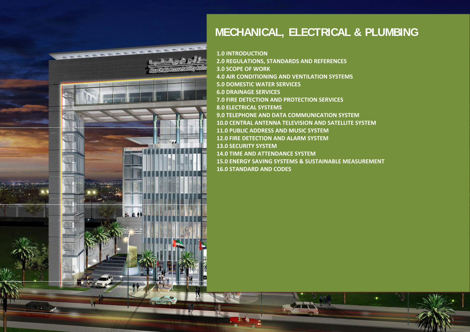
MECHANICAL, ELECTRICAL & PLUMBING
1.0 INTRODUCTION2.0 REGULATIONS, STANDARDS AND REFERENCES 3.0 SCOPE OF WORK 4.0 AIR CONDITIONING AND VENTILATION SYSTEMS 5.0 DOMESTIC WATER SERVICES 6.0 DRAINAGE SERVICES 7.0 FIRE DETECTION AND PROTECTION SERVICES 8.0 ELECTRICAL SYSTEMS 9.0 TELEPHONE AND DATA COMMUNICATION SYSTEM 10.0 CENTRAL ANTENNA TELEVISION AND SATELLITE SYSTEM 11.0 PUBLIC ADDRESS AND MUSIC SYSTEM 12.0 FIRE DETECTION AND ALARM SYSTEM 13.0 SECURITY SYSTEM 14.0 TIME AND ATTENDANCE SYSTEM 15.0 ENERGY SAVING SYSTEMS & SUSTAINABLE MEASUREMENT 16.0 STANDARD AND CODES

MECHANICAL, ELECTRICAL & PLUMBING 2
1.0 INTRODUCTION
1.1 Purpose
The purpose of this MEP proposal is to establish key design criteria, methods of servicing, primary distribution routes and locate major items of the electrical and mechanical systems.
2.0 REGULATIONS, STANDARDS AND REFERENCES
2.1 Publications, Standards and References
All work shall be carried out in accordance with the requirements of the local authorities and the standards and codes included hereinafter.
ARI American Refrigeration Institute
ASHRAE American Society of Heating, Refrigerating and Air Conditioning Engineers Inc.
ASTM American Society of Testing Materials
SMACNA Sheet Metal and Air Conditioning Contractors National Association
NFPA National Fire Protection Association
UL Under writers Laboratory
IEE Institution of Electrical Engineers
IEC International Electro‐technical Commission
IOS International Organization of Standardization
ADDC Abu Dhabi Distribution Company
ADSSC Abu Dhabi Sewerage Service Company
ADCD Abu Dhabi Civil Defense Authority
ETISALAT Local Telecom Authority
CIBSE Chartered Institution of Building Services Engineers
BSI British Standards Institution
2.2 Materials
All materials used on the project shall be brand new and of high quality.
“New” is defined as newly manufactured, “state of the arts,” tested and proven item of equipment. Items which have been held in stock for any extended period of time by either the manufacturer or the supplier shall be rejected.
All materials used on this project shall bear the third party quality assurance stamp like British Standard kitemark, UL, FM, LPC and/or other quality assurance authority as stated herein.
3.0 SCOPE OF WORK
3.1 Mechanical Services
The following services shall be provided for the project:
3.1.1 Air Conditioning
‐ Central air‐conditioning and ventilation.
3.1.2 Plumbing & Drainage
‐ Cold and hot water services network.
‐ Filtration of cold water services.
‐ Gravity drains connected to the city drainage network.
3.1.3 Fire Protection

MECHANICAL, ELECTRICAL & PLUMBING 3
‐ Automatic hose reels for use by occupants.
‐ Dry riser and landing valves for use by the fire department.
- Sprinkler system. - Fire extinguishers
3.1.4 Building Management system

MECHANICAL, ELECTRICAL & PLUMBING 4
4.0 AIR CONDITIONING AND VENTILATION SYSTEMS
4.1 Design Parameters
Design in general shall be based on ASHRAE 62‐2007 recommendations in addition to the following practical requirements.
4.1.1 Design Conditions
External : 46 ºC DB, 29.4 ºC WB
(Summer)
Internal : 23ºC DB, RH 50% + 5% (No specific humidity controls and resultant relative humidity will be function of set point temperature).
: No winter heating shall be provided.
4.1.2 Ventilation, Occupancy and Heat Dissipation Requirements
Area Ventilation Occupancy Heat Dissipation due to Lighting and Power
Offices 8.5 L/s/person 20 m²/person 40 w/m²
Meeting room
3.1 L/s/person 2 m²/person 40 w/m²
Coffee shop
4.7 L/s/person 1 m²/person 40 w/m²
Retail 7.8 L/s/person 6.7 m²/person 70 w/m²
Circulation/Corridor
0.3 L/s/m2 ‐‐ 20 w/m²
Area Ventilation Occupancy Heat Dissipation due to Lighting and Power
Storage rooms
0.12 L/s/m2 ‐‐ 10 w/m²
Reception areas
3.5 L/s/person 3.3 m²/person 40 w/m²
Main entry lobbies
5.5 L/s/person 10 m²/person 40 w/m²
Prayer rooms
2.8 L/s/person 0.83 m²/person
20 w/m²
Galleries/show rooms
4.6 L/s/person 2.5 m²/person 70 w/m²
For other areas refer to ASHRAE Standard 62‐2007.
Extract Air System
Area Extract Air
Public Toilet
25 L/s
4.1.3 Noise Levels
‐ Offices/Meeting Rooms NC 35
‐ Corridors & Public Areas NC 40
‐ Toilets NC 40
‐ Plant rooms NC 50

MECHANICAL, ELECTRICAL & PLUMBING 5
4.1.4 Air Filtration
a) Air filtration shall be based on ASHRAE 52‐76.
b) Fresh Air handling units shall have two banks of filters. Panel filter at 25% ‐ 30% efficiency and bag filter at 85% ‐ 90% efficiency.
c) Fan coil units shall have 25mm thick cleanable panel filter at 25% efficiency.
4.2 System Description
4.2.1 Air Conditioning
Option – 1
Air cooled chillers on the roof of the building to serve FCUs/AHUs through chilled water network.
Although this option is simple and common, the following disadvantages are obvious:
a) Bulky installation on building roof.
b) Standby chiller shall be considered, i.e. dead capacity.
c) Major source of noise
Option – 2
Variable Refrigerant Volume System (VRV). The system comprises of modular outdoor unit connected with multi indoor units via refrigerant piping network.
The system offers a considerable reduction of refrigerant flow as per the cooling load demand which will lead to a considerable energy reduction.
All indoor spaces shall be served with ducted indoor units.
a) Advantages
1) Limited/compacted space required on roof for outdoor units installation.
2) When integrated with control systems, the performance can be optimized to achieve low energy consumption.
b) Disadvantages
1) System spare parts including pipe fittings and manifolds are limited to the equipment supplier.
2) System cost is higher than option‐1.
3) Cooling capacity of the system is limited.
4) Fresh air handling unit shall be provided with separate conventional Direct Expansion (DX) – condensing unit due to the limitation of cooling capacity for VRV‐system.
Recommendation:
It is recommended to use Option‐2.
4.2.2 Ventilation
a) Central fresh air handling unit shall be provided. Fresh air shall be delivered to all indoor units via insulated duct riser.
MECHANICAL, ELECTRICAL & PLUMBING 6
b) FAHU shall have heat recovery section for energy saving.
c) Extract air shall be taken from toilets and pantries and ducted to the heat recovery section of FAHU via duct risers.
4.2.3 Heat Recovery System
Thermal wheel shall be provided in the FAHUs in order to recover energy from the extract air and pre‐cool the intake air to FAHUs, thus reducing the cooling load of FAHU coil for energy saving.
5.0 DOMESTIC WATER SERVICES
5.1 Design Parameters
The design shall be based on the recommendation of the Chartered Institution of Building Services Engineers and the Regulations of the Local Water Utilities Company. The following general guidelines shall be followed:
a) Water velocity shall be limited to about 2.5m/s. to avoid water flow noise.
b) The temperature of the stored hot water shall not exceed 65oC.
c) Dead legs to hot water draw off points shall be kept as short as possible.
d) Thermal and protective insulation of pipework shall be provided as specified.
e) Water storage tank shall be provided for domestic water consumption along with the minimum fire reserve as stipulated by the local Civil Defence Authority.
f) Over head water storage tank shall be provided for domestic water consumption.
g) The booster pump shall be sized to supply water to al outlets while maintaining a water pressure in the range of 2.0 to 3.5 bar at the outlets.
h) Pressure regulation valves shall be provided as necessary to limit the pressure within the maximum permissible limits.
i) Water meters location shall be accessible to ADDC personnel.
5.2 System Description
5.2.1 Cold Water System
a) From the water mains, an incoming water line shall be connected to the main underground concrete (RCC) water storage tank (1.5 daily demand capacity.
b) Water from underground water tank shall be transferred via lifting pumpset to the overhead tanks, which has to be located above the floors served by these respective tanks.
c) The overhead tanks shall have 1 daily demand as a domestic reserve for the floors served by the respective tank.
d) Water supply to shall be toilets/pantries through booster pump set to maintain minimum 1.5 bar pressure at the draw‐off points.
e) Water meter shall be provided on the incoming water line to the U/G main water tank.
5.2.2 Hot Water System
Hot water to the public toilets/pantries shall be provided through individual electric water heater installed within the ceiling void of the wet areas.
6.0 DRAINAGE SERVICES
MECHANICAL, ELECTRICAL & PLUMBING 7
6.1 System Design
This will be a gravity drainage system designed in accordance with the recommendation of the Charted Institution of Building Services Engineers (CIBSE) to the requirements of the Abu Dhabi Municipality – Town Drainage Department.
6.2 System Description
All work shall be installed and tested in accordance with BS5572 Code of Practice for sanitary work and to the satisfaction of the local Drainage Department. The internal drainage system shall comprise of two stacks (soil and waste) with a separate vent pipe. All drainage shall be discharged into the city sewer main through a series of gully traps and manholes, as required.
A separate rain water system shall be installed to collect rainwater from the roof and discharge at agreed locations on to pavement or to discharge into the city storm water main through a series of catch basins and storm water manholes, as required.

MECHANICAL, ELECTRICAL & PLUMBING 8
7.0 FIRE DETECTION AND PROTECTION SERVICES 7.1 System Design
All systems shall be designed in accordance with the requirements as set out in the relevant British Standards, NFPA and to the requirements of the Local Civil Defence Authority.
The various systems to be provided for this project are:
a) Automatic fire hose reels. b) Dry riser with landing valves for use by the fire service personnel. c) Automatic sprinkler system. d) Fire extinguishers.
7.2 System Description
7.2.1 Automatic fire hose reels
This system shall primarily be for use by the occupants and used as a first aid means of fighting a fire whilst awaiting the arrival of the Local Fire Brigade.
The fire hose reel pipework shall be connected to the fire mains through a pressure reducing valve so as to maintain the system under pressure and to automatically release a jet of water when any hose is uncoiled.
Fire hose reels shall be located such that these are readily accessible and that these can cover all areas of the building with no part being more than 6 meters from the hose reel nozzle when the hose is uncoiled.
7.2.2 Dry Riser with Landing Valves
This system shall be provided solely for use by the fire service personnel and shall consist basically of one or more pipes rising vertically up the building with hydrant valve outlets on each floor and at roof level. Landing valves shall be located within the same cabinet to be used for fire hose reels.
7.2.3 Automatic Sprinkler System
The project shall be provided with an automatic sprinkler installation, classified and designed in accordance to NFPA 13 rules for automatic sprinkler installation.
The sprinkler system shall be continuously maintained under pressure by fire pumps installed within the pump room and serving sprinkler and automatic fire hose reels. The sprinkler system shall consists of a network of piping with water always maintain the system under pressure. Fusible sprinkler heads shall be screwed into the piping at interval as recommended by NFPA regulations.
In the event of a fire, the heat generated shall cause the fusible element in the adjacent sprinkler head to disintegrate and thus allow water to be discharged onto the fire in the form of a fire spray.
At the same time as water is discharged onto the fire, water shall also be allowed to flow to a water turbine which in turn shall operate an alarm gong thus giving an audible alarm that the system has operated. The system shall also be interfaced with the fire alarm panel in order to actuate fire alarm bells in a fire situation.
7.2.4 Fire Extinguishers
Shall be dry powder and/or carbon dioxide as required by the local authorities
MECHANICAL, ELECTRICAL & PLUMBING 9
8.0 ELECTRICAL SYSTEMS 8.1 General
The following systems shall be provided for the project:
a) High Voltage System b) Low Voltage Electrical Distribution c) Emergency Power Supply through Standby Generator d) Lighting and Small Power Distribution System e) Lighting control System f) Central Battery Emergency Lighting System g) Earthing System h) Lightning Protection System i) Security and CCTV System j) Fire Alarm System k) Public Address and Background Music System l) Voice and Data Systems m) Central Antenna and Satellite System n) Building management system
8.2 Codes & Standard:
The electrical installation shall in general be designed to meet the following codes, standard and requirement of:
a) NEC National Electrical Code b) NFPA National Fire Protection Association c) UL Underwriters Laboratories d) IEEE Institute of Electrical and Electronic Engineer e) IES illuminating Engineering society f) IEC International Electro‐technical Committee g) TIA Telecommunications Industry Association h) ADDC Abu Dhabi Distribution Company i) RSB Regulation and Supervision Bureau j) ETISALAT Local Telecom Company k) ADCD Abu Dhabi Civil Defense l) BSI British Standards Institution m) CIBSE Charter Institute of Building Services Engineers
The installation shall also be designed to protect persons, property and livestock against hazard of electric shock, fire burns and injury from mechanical movement of electrically actuated equipment.
Integration of mechanical and electrical discipline with the architectural design and adequate space for electro mechanical services shall be provided to improve systems maintainability and reliability and to integrate the same with the surrounding architectural appearance.
All electrical equipment shall be compensated to give the rated output at 35 °C for internal installation and at 45 °C for the external installation.
8.3 Electrical Load Assessments:
The preliminary building load estimation shall be based on power density assumptions that apply to the general space programs. As the utilization of spaces and other building systems are more defined, the load estimation shall be provided accordingly.
.
8.4 High Voltage System
HV primary ring feeders shall be derived from the nearest primary substation in coordination with Infrastructure Consultant.
The HV feeders shall power the ring main unit (TRM) rated to carry the total building load and facilitate full redundancy in the event of one source or feeder failure.
The supply cables shall be routed from primary substation to the building via the underground concrete encased electrical duct banks. In the buildings, the cables shall be terminated in the TRM which in turns will provide HV feeder for the transformer within the transformer room. From the LV side of the transformer LV cables shall be routed to the LV room to feed the main low voltage switchgears, from which further distribution will be provided to the entire building via cables as detailed hereafter:
The substation shall consist of high voltage room, transformer room, Generator room, etc. The LV room will be located within the building at the edge near to the substation to optimize cable runs. The exact arrangement of the sub station including the transformers and HV panels shall be as agreed with ADDC.

MECHANICAL, ELECTRICAL & PLUMBING 10
8.5 Low Voltage System
The low voltage side of the transformers shall be connected to the low voltage panel located in the LV room. The LV panel shall be constructed to the requirement of BSEN 60439‐1
The low voltage (LV) installation shall consist of 1600A main distribution boards (MDB) in LV rooms located below the substations and motor control centers (MCC) for the chiller plants, sub-main distribution boards (SMDB) and final distribution boards (DB).
Single core armoured cables from LV side of the transformers shall feed the MDB incomer circuit breaker. Outgoing air / moulded case circuit breakers (ACB / MCCB) shall feed SMDBs and MCCs through cables.
Low voltage system shall consist of the following:
8.5.1 Main Distribution Boards (MDB)
The construction of the main distribution boards shall comply with (form 2B, type 2 or Form 4B, type 6) requirements of IEC‐439‐1 based on Client’s recommendation. The boards shall be constructed to withstand a short circuit current of 50kA for 1 second, which is considered as a safe short circuit protection level. Ingress protection shall be to IP 41.
8.5.2 Main Distribution Boards construction details (MDB)
Option: 1
Form 2b, type 2 assemblies
Form 2b, type 2 covers overall assemblies which are so enclosed as to provide protection against contact with some internal live parts and components but where there is internal separation of the busbars from functional units.
i. Busbars are separated from functional units.

MECHANICAL, ELECTRICAL & PLUMBING 11
ii. Functional units are not separated from functional units.
iii. The busbar separation is achieved by metallic or non‐metallic rigid barriers, or partitions.
iv. Terminals are therefore separated from the busbars from functional units or each other’s.
Option: 2
Form 4B, type 6 assemblies
Form 4B, type 6 covers overall assemblies which are so enclosed as to provide protection against contact with internal live parts and components and in which there is internal separation of the busbar system from functional units and separation of all functional units from one another. Incoming and outgoing terminals are also separated from the busbars and from each other.
i. Busbars are separated from functional units.
ii. Functional units are separated from each other.
iii. Terminations to functional units are separated from each other.
iv. Incoming and outgoing terminals are separated from each other and from other terminals.
v. The busbar separation is by metallic or non‐metallic rigid barriers, or partitions. Terminals are separated by insulated coverings and glanded in common cabling chambers.
The following LV panel forms construction to be advised by the client in terms of cost:
Option Form Yes No
1 Form 2B Type 2
2 Form 4B Type 6
From the LV panel cables shall be routed to feed the power to the submain panels located in various electrical rooms of each floor.
8.5.3 Sub Main Distribution Board
The construction of the sub‐main distribution boards shall comply with form 2, type 2 requirements of IEC‐439‐1. The boards shall be constructed to withstand a short circuit current of 30kA. Ingress protection shall be to IP 41. The sub‐main distribution boards shall be located in every floor of the building.
In general, SMDBs shall be provided to feed final distribution boards isolators in every floor.
8.5.3.1 Form 2, type 2 assemblies
Form 2 covers overall assemblies which are enclosed as to provide protection against contact with any internal live parts or components, and where there is internal separation of the busbars from functional units and their terminations.
i. Busbars are separated from functional units and incoming and outgoing terminals.
ii. Functional units are not separated from other functional units.
iii. Functional units are not separated from any incoming or outgoing terminals.
iv. Busbar separation is achieved either by insulated covering (e.g. sleeving, wrapping or coating) or by metallic or non–metallic rigid barriers or partitions.
The LV panel and the sub main distribution shall be arranged such that maximum flexibility is available to respond to any extra power.
MECHANICAL, ELECTRICAL & PLUMBING 12
8.5.4 Final Distribution Boards
From the dedicated SMDB each electrical room armoured cables on heavy duty cable tray shall feed the final distribution boards (DB) located within the electrical room and which shall feed final lighting and power circuits.
The final distribution boards shall be split busbar type and shall be provided with isolator as incomer and miniature circuit breakers (MCBs) as outgoings with common RCD protection for each section of MCBs. The minimum short circuit rating for final DBs and circuit breakers shall be 10 KA.
The LV switchgear and the sub‐main distribution shall be arranged such that maximum flexibility is available to respond to any extra power.
Cables within the building shall be routed through cable trays, but all external underground installation shall be using concrete encased uPVC ducts and manholes.
All cable shall be sized such that the current carrying capacity at 50 deg. C is equal or higher to the rating of the breaker protecting the cable, method of installation of the cable and the spacing between adjacent cables shall be taken into consideration in determining the cable current capacities.
The cables shall also be sized to limit the voltage drop between the main panel boards to the final power consumption point to 4% of the nominal voltage.
8.5.5 Starter Panels
Local starter panels shall be provided for equipment not controlled from motor control centers. These panels shall be constructed as per form 2, type 2 Standards.
8.5.6 Capacitor Banks
8.5.6.1 Reactive Power Compensation
Electrical networks which include major inductive loads (e.g. motors) shall operate under poor overall lagging power factor conditions. Also, in case these inductive loads are constantly being switched on and off (e.g. HVAC equipment motors), the power factor of the overall system shall change with every switching operation. A poor power factor is a major (and avoidable) cost factor. There are basically three methods which are commonly used to compensate for the inductive power drawn by a load or an electrical installation, and thereby improve its power factor.
Option‐1:
Individual Compensation
In the case of individual compensation, the capacitors are connected directly to the terminals of the individual loads and are switched in and out of circuit by the same common switching device. The chillers shall be provided with its own PFC capacitors to improve the power factor to 0.95.
Option‐2:
Group Compensation
In this case, the power factor correction equipment provides a fixed value compensation for a number of motors or e.g. fluorescent lamps which are switched as a group by means of a common contactor or circuit – breaker.
Option‐3:
Centralized Compensation
In most cases power factor correction units, which automatically switch power capacitors into or from the load circuit, are used for centralized power factor correction. They are usually directly associated with, and installed centrally at, a particular switchboard, distribution board or incoming supply.
MECHANICAL, ELECTRICAL & PLUMBING 13
8.5.6.2 Selection of Type of Compensation
The most suitable type of compensation is arrived at based on a number of technical and economical aspects. Generally, central power factor correction units have a higher price per installed kVAR. As a guideline, it has been found that the cost of the two methods is comparable for a diversity factor (or load factor) as high as 0.7 to 0.8. If the diversity factor is lower, the centralized method of compensation becomes more attractive.
In general, the system proposed for the project is centralized compensation which also complies with ADDC requirements. The chillers shall have its own PFC capacitors as part of the soft starter.
Capacitor banks shall be provided to improve the system power factor to greater than 0.90 lagging and shall be installed across the MDB. An automatic power factor regulator shall continuously sense the power factor condition across the MDB and shall switch on or off capacitors to maintain the overall power factor greater than 0.90 lagging.
Special filters shall be provided for capacitors to withstand transient harmonic currents in the system. The capacitor panel shall be located adjacent to the MDBs.
The capacitor banks shall be constructed to IEC‐831 standard and capacitor bank enclosures shall comply with IEC‐439‐1.
8.5.8 Energy Metering
Energy meters shall be provided as follows:
Main meter as per ADDC requirement for LV Panels sub metering according to client requirements. In addition to the above, energy monitoring units (EMU) shall be installed in MDBs for remote monitoring of power consumption, voltage, current, frequency etc. of each panel on the building management system.
8.5.8.1 Dedicated Motor Control Center (MCC) shall be provided at appropriate location near the chiller plant to feed the HVAC system equipment.
8.6 Emergency Power Supply system
A low voltage (415 V, 3 Phase emergency generator and its dedicated distribution system shall be provided to power primarily the life‐safety equipment and devices.
The fuel storage tank shall be sized to store enough fuel for 1 days of generator run time.
Limited amount of power shall be available to back up some of non safety equipment in the building that required functioning during the power failure.
The generator shall be located in the service block to ensure proper ventilation and near the substation to reduce cable runs.
A dedicated Emergency Sub Main distribution board shall be provided for the building with a feeder from the sub station generator panel and shall be located in the LV room for feeding all the essential services of the building Further power distribution from the emergency MSMDB shall be similar to the normal power distribution using sub main distribution boards and final distribution boards to be located at the various electrical rooms and fed by cables on cable tray: The essential services shall also include the following:
a) 40% of the lighting in the corridors and 25 to 30% of the general public area lighting.
b) 100% of the fire escape lighting
c) Elevator(s)
d) Service elevator
e) Domestic water pumps
f) Sump pumps
g) Control, security and main telecom room.
h) Smoke extract fans, staircase fans, etc
MECHANICAL, ELECTRICAL & PLUMBING 14
i) Life and safety equipment such as fire alarm system, public address, CCTV system, security system, BMS, etc...
j) UPS
Emergency power generators can be provided 100 % back up subject to client request.
8.7 Un-Interruptible Power Supply (UPS)
An Un‐interruptible Power Supply (UPS) unit with battery backup will be provided in order to maintain continuous power supply be provide to the main server and various IDTs. Autonomy time will be 30 minutes.
8.8 Lighting
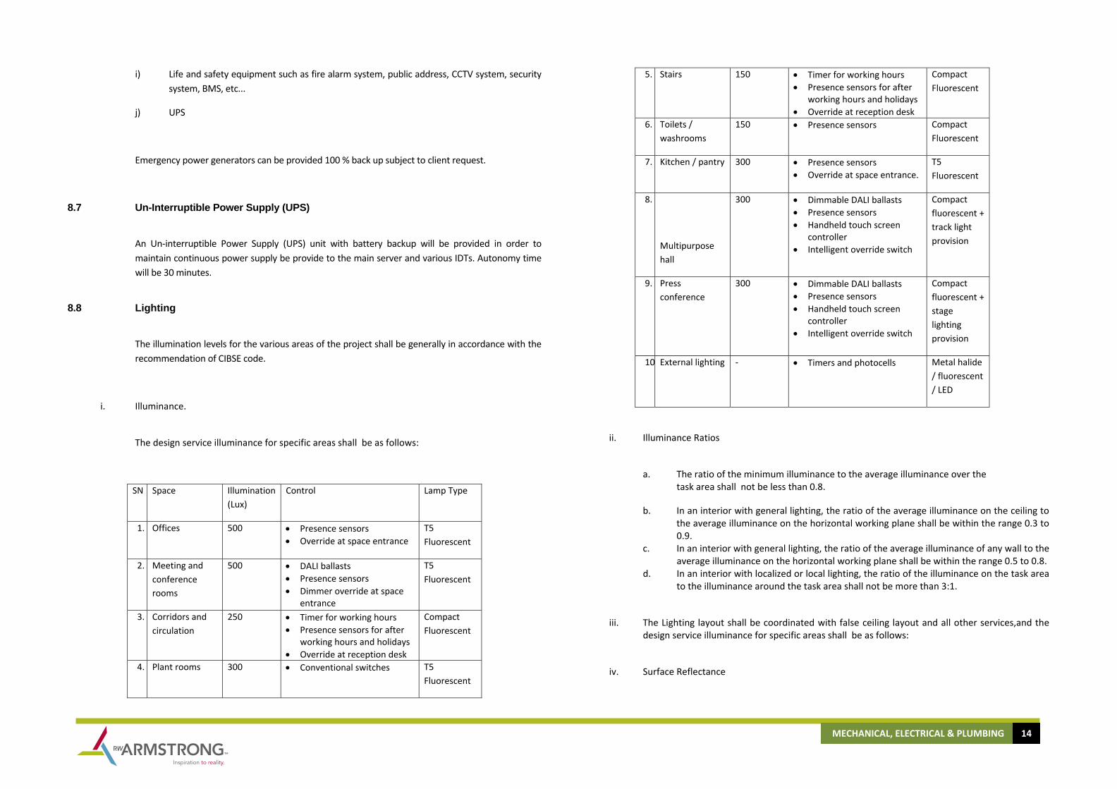
The illumination levels for the various areas of the project shall be generally in accordance with the recommendation of CIBSE code.
i. Illuminance.
The design service illuminance for specific areas shall be as follows:
SN Space Illumination (Lux)
Control Lamp Type
1. Offices 500 • Presence sensors • Override at space entrance
T5 Fluorescent
2. Meeting and conference rooms
500 • DALI ballasts • Presence sensors • Dimmer override at space
entrance
T5 Fluorescent
3. Corridors and circulation
250 • Timer for working hours • Presence sensors for after
working hours and holidays • Override at reception desk
Compact Fluorescent
4. Plant rooms 300 • Conventional switches T5 Fluorescent
5. Stairs 150 • Timer for working hours • Presence sensors for after
working hours and holidays • Override at reception desk
Compact Fluorescent
6. Toilets / washrooms
150 • Presence sensors Compact Fluorescent
7. Kitchen / pantry 300 • Presence sensors • Override at space entrance.
T5 Fluorescent
8.
Multipurpose hall
300 • Dimmable DALI ballasts • Presence sensors • Handheld touch screen
controller • Intelligent override switch
Compact fluorescent + track light provision
9. Press conference
300 • Dimmable DALI ballasts • Presence sensors • Handheld touch screen
controller • Intelligent override switch
Compact fluorescent + stage lighting provision
10 External lighting ‐ • Timers and photocells Metal halide / fluorescent / LED
ii. Illuminance Ratios
a. The ratio of the minimum illuminance to the average illuminance over the task area shall not be less than 0.8.
b. In an interior with general lighting, the ratio of the average illuminance on the ceiling to the average illuminance on the horizontal working plane shall be within the range 0.3 to 0.9.
c. In an interior with general lighting, the ratio of the average illuminance of any wall to the average illuminance on the horizontal working plane shall be within the range 0.5 to 0.8.
d. In an interior with localized or local lighting, the ratio of the illuminance on the task area to the illuminance around the task area shall not be more than 3:1.
iii. The Lighting layout shall be coordinated with false ceiling layout and all other services,and the design service illuminance for specific areas shall be as follows:
iv. Surface Reflectance
MECHANICAL, ELECTRICAL & PLUMBING 15
Surface reflectance as detailed below shall generally be considered:
a. The ceiling cavity reflectance shall be as high as practicable and generally at least 0.6. This shall usually mean that the reflectance of the paint or other surface finish must be at least 0.8.
b. The effective reflectance of the principal walls shall be between 0.3 and 0.7. This usually means that the walls surface finish shall have to have an actual reflectance greater than 0.5. The reflectance of window wall surfaces shall be at least 0.6 to reduce contract with the bright scene outdoors during day time.
c. Where practical, floor cavity reflectance shall be within the range 0.2 to 0.3. This usually means that the relevant surfaces shall have to have a reflectance greater than 0.3.
d. It is desirable for equipment and furnishings in working interiors, and in particular desk tops, to have finishes with a reflectance of not less than 0.2.
v. Colour
Where accurate colour judgments are to be made, care shall be taken to select proper colour rendering group.
vi. Glare
a. Luminous ceilings utilizing large diffusing panels are not recommended for lighting interiors. In any case, the average luminance of such luminous ceiling should not be greater than 500cd/m2.
b. For indirect lighting, the average luminance of the ceiling should not be more than 500cd/m2.
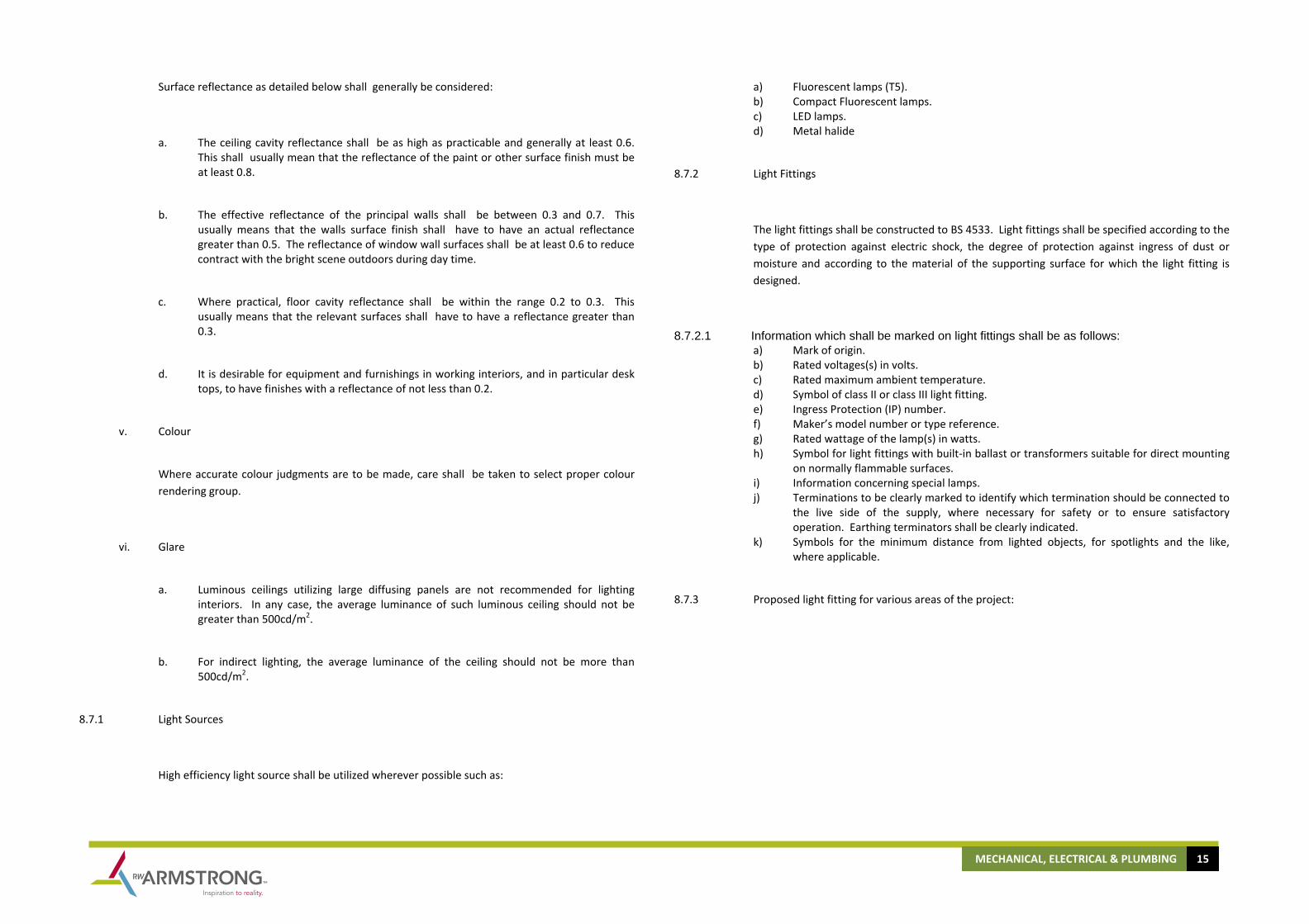
8.7.1 Light Sources
High efficiency light source shall be utilized wherever possible such as:
a) Fluorescent lamps (T5). b) Compact Fluorescent lamps. c) LED lamps. d) Metal halide
8.7.2 Light Fittings
The light fittings shall be constructed to BS 4533. Light fittings shall be specified according to the type of protection against electric shock, the degree of protection against ingress of dust or moisture and according to the material of the supporting surface for which the light fitting is designed.
8.7.2.1 Information which shall be marked on light fittings shall be as follows: a) Mark of origin. b) Rated voltages(s) in volts. c) Rated maximum ambient temperature. d) Symbol of class II or class III light fitting. e) Ingress Protection (IP) number. f) Maker’s model number or type reference. g) Rated wattage of the lamp(s) in watts. h) Symbol for light fittings with built‐in ballast or transformers suitable for direct mounting
on normally flammable surfaces. i) Information concerning special lamps. j) Terminations to be clearly marked to identify which termination should be connected to
the live side of the supply, where necessary for safety or to ensure satisfactory operation. Earthing terminators shall be clearly indicated.
k) Symbols for the minimum distance from lighted objects, for spotlights and the like, where applicable.
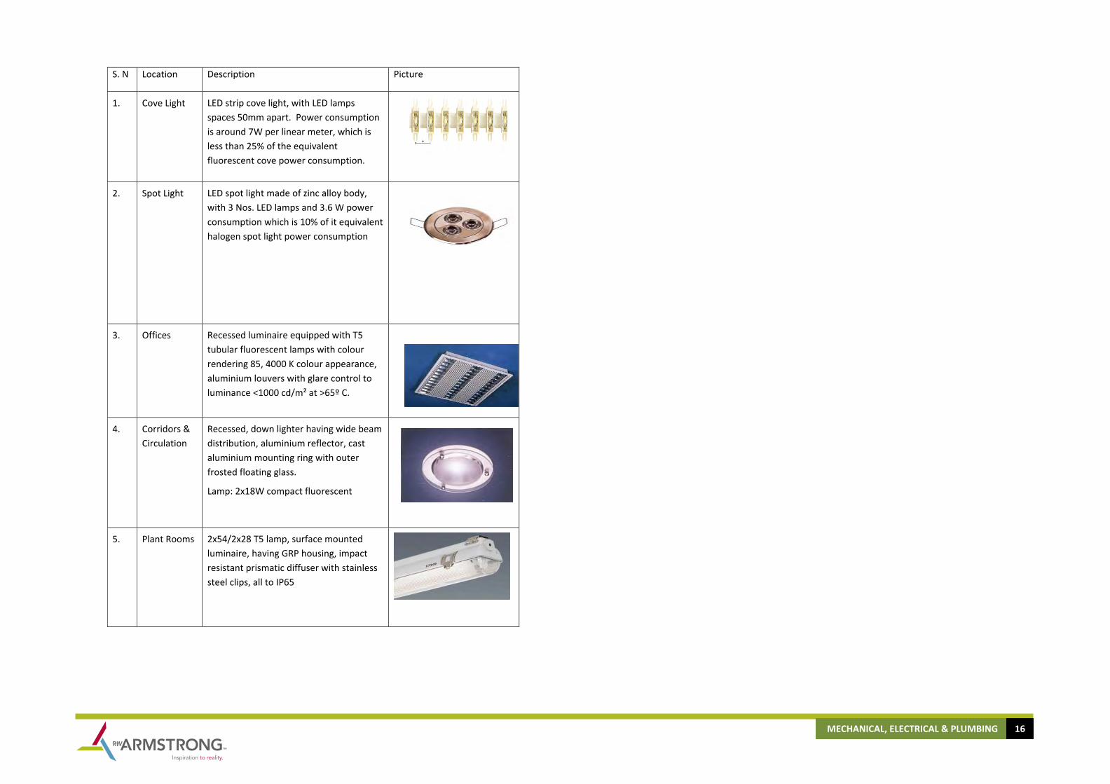
8.7.3 Proposed light fitting for various areas of the project:
MECHANICAL, ELECTRICAL & PLUMBING 16
S. N Location Description Picture
1. Cove Light LED strip cove light, with LED lamps spaces 50mm apart. Power consumption is around 7W per linear meter, which is less than 25% of the equivalent fluorescent cove power consumption.
2. Spot Light LED spot light made of zinc alloy body, with 3 Nos. LED lamps and 3.6 W power consumption which is 10% of it equivalent halogen spot light power consumption
3. Offices Recessed luminaire equipped with T5 tubular fluorescent lamps with colour rendering 85, 4000 K colour appearance, aluminium louvers with glare control to luminance <1000 cd/m² at >65º C.
4. Corridors & Circulation
Recessed, down lighter having wide beam distribution, aluminium reflector, cast aluminium mounting ring with outer frosted floating glass.
Lamp: 2x18W compact fluorescent
5. Plant Rooms 2x54/2x28 T5 lamp, surface mounted luminaire, having GRP housing, impact resistant prismatic diffuser with stainless steel clips, all to IP65

MECHANICAL, ELECTRICAL & PLUMBING 17
6.
Façade Lighting
Powerful LED façade lighting with 3W LED lamps. With colour changing feature. Body made of aluminium alloy, toughened glass to IP 65.
7.
External
Lighting (Building Perimeter at ground floor)
Wall luminaire with optical system allowing light from one lamp to merge in two directions with narrow upward beam and wide down ward beam. 70W metal halide lamp, aluminium alloy body anodized aluminium reflector, IP65.
8. Roof Robust luminaire made of die‐cast aluminium and thick walled crystal glass with optical texture, 1x26W compact flourescent lamp, IP55.
9. Toilet Recessed luminaire equipped with compact fluorescent lamp with colour rendering 85, 3000 K colour appearance, glass diffuser, IP44.
10. Server Rooms, Control Rooms
Recessed luminaire equipped with T5 lamps and glare control to luminance <1000 cd/m² at >65º.
Colour rendering 85 and colour temperature 4000 K.
11. Lobbies Entrances
Decorative recessed circular down lighter with two lamps (T5 Lamps)

MECHANICAL, ELECTRICAL & PLUMBING 18

MECHANICAL, ELECTRICAL & PLUMBING 19
8.8 Wiring Accessories
8.8.1 General Purpose Socket Outlet
General purpose 13A switched socket outlets shall be provided throughout the proposed development.
All areas including plant rooms, roofs, stores, mechanical equipment rooms, corridors, lobbies etc. shall be considered.
The switched socket outlets shall be in accordance with BS 1363 and BS 546 as appropriate. Minimum number of outlets provided in each area shall be as follows:
Entrances and Lobbies : 1 Outlet / 15m2
Corridors and Circulation Areas : 1 Outlet / 15m2
Pantry / Kitchen : To suit equipment layout
Receptions : One twin 13 ASSO for each work station.
Workstations : One Twin 13A SSO per workstation
8.8.2 Local Switches
Switches shall be grid type of the quick start make, slow break type specially designed for AC circuit to BS 3676. Switches shall be 20A grid type.
8.8.3 Finish of Wiring Accessories
All accessories in wet and damp areas shall be of the splash proof type to IP 55 protection standard.
All accessories in plant rooms shall be with metal clad finish.
All accessories above False Ceiling shall be white plastic finish.
The wiring accessories finishes in the public areas such as main entrance, lift lobbies, etc… shall be either one of the following based on Client’s instruction:
SN Location
Wiring accessories finish
Remarks Slim
crewless metallic finish
Slim screwless white
polycarbonate
Slim screwless coloured
polycarbonate
1. Offices / workstations
2. Circulation areas
3. Multipurposehall
4. Press conference & auditorium
5. Reception
6. Leasable spaces
8.9 Lighting Control System
Programmable lighting control based on distributed intelligence system shall be provided for controlling the lighting at the various areas.

MECHANICAL, ELECTRICAL & PLUMBING 20
The system shall automatically switch the lights on and off in pattern as programmed and with features of changing the timing and type of lights controlled within a group.
All internal area lighting shall be controlled through timers and presence sensors. All external lighting including those of building facial, landscaping, road/pathway, parking etc shall be controlled through timer and photocells. As detailed in the lighting section
The system shall receive a signal through the fire alarm panel to switch all the lights ON during fire and the lights connected to emergency power supply during power failure
8.10 Emergency Lighting system
8.10.1 Emergency and Fire Exit Lights
The task of emergency lighting is to provide safety lighting meant to evacuate a building without risk. Emergency lighting systems are generally of two options:
a) Self Contained type, wherein the battery pack is contained in the light fitting itself. b) Central Battery system, wherein the battery pack is centralized for a group of light
fittings and is remotely located. The system proposed for the project is central battery system as it has the following advantages over self contained type light fittings:
a) High safety level due to decentralized configuration.
b) Fully automatic periodic testing facility, whereby any faulty light fitting can be immediately detected.
c) Fully automatic monitoring facility.
d) Freely programmable control module.
e) Continuous battery charge monitoring.
f) Very low operating costs.
g) No power loss from ballasts since ballasts are electronic and hence energy saving.
h) Easy maintenance.
i) Periodic function test on all lamps, ballasts etc.
j) Yearly tests.
k) Display of current consumption and status information.
l) Print – out facility.
m) Extended lamp life.
n) Environment friendly maintenance – free lead accumulator battery with a recycling rate of > 96%, over standard pollution prone nickel cadmium battery.
o) Interface with BMS for central control.
The Central Battery Emergency system will be based on DC system as per IEC 598-2-22 standard.
Emergency lights in the public areas shall be part of the light fittings used in that area. Separate slave emergency luminaries shall be used in other areas including offices, shops, plant rooms, sub station, store, etc.
Slave emergency luminaires shall be recess mounted in the offices and shops and surface mounted in service areas.
8.10.2 Aircraft Warning Light
Becon strobe light shall be provided for the project for aircraft warning to satisfy the requirements of the Civil Aviation Authority.
8.11 Main Earthing System
The complete electrical installation shall be mechanically and electrically continuous throughout and shall be bonded to the main earth.
An earth resistance value of 1ohm or less shall be achieved in the main earth pits.
Earth continuity conductor shall be provided from main panel up to each final circuit termination point.

MECHANICAL, ELECTRICAL & PLUMBING 21
All conductive but non‐current carrying installations shall be equipotential bonded to the main earthing system. The conductive installations shall include the following (as per BS 7430, Clause 20.4):
a) Water pipes. b) Sprinkler and fire fighting pipes. c) HVAC ducting. d) Pipe risers of HVAC systems. e) Exposed metallic parts of the building. f) Lightning conductors.
8.12 Lightning Protection System
8.12.1 Effects of Lightning Strike
8.12.1.1 Electrical Effects As the current is discharged through the resistance of the earth electrode of the lightning
protection system, it produces a resistive voltage drop which may momentarily raise the potential of the protection system to high value relative to true earth. It may also produce around the earth electrode a high potential gradient dangerous to people and animals.
8.12.1.2 Side Flashing The point of strike on the protection system may be raised to a high potential with respect to
adjacent metal. There is therefore a risk of flashover from the protection system to any other metal on or in the structure. If such flashover occurs, part of the lightning current is discharged through internal installations, such as pipes and wiring, and so this flashover constitutes a risk to the occupants and fabric of the structure.
8.12.1.3 Thermal Effects For the purposes of lightning protection, the thermal effect of a lightning discharge is
confined to the temperature rise of the conductor through which the current passes. Although the current is high, its duration is short and the thermal effect on the protection system is usually negligible.
In general, the cross-sectional area of a lightning conductor is chosen primarily to satisfy the
requirements of mechanical strength, which means that it is large enough to keep the rise in temperature to 1°C.
8.12.1.4 Mechanical Effects
Where a high current is discharged along parallel conductors in close proximity or along a single conductor with sharp bends, considerable mechanical forces are produced.
Similarly, with a side-flash inside the building, the shock wave can result in damage to the
building fabric.
8.12.1.5 Function of a Lightning Conductor
A lightning conductor is incapable of discharging a thunder cloud without a lighting flash. Its function is to divert to itself a lightning discharge which might otherwise strike a vulnerable part of the structure to be protected and to convey the current safely to earth. The range over which a lightning conductor can attract a lightning flash is not constant but it is now believed to be a function of the severity of the discharge.
The range of attraction is therefore a statistical quantity.
On the other hand, the range of attraction is little affected by the configuration of the conductor, so that vertical and horizontal arrangements are equivalent. The use of pointed air terminations or vertical finals are therefore not regarded as essential, except where dictated by practical considerations.
8.12.1.6 Need for Protection
The following situations are to be considered while ascertaining the need for protection:
a) Where large numbers of people congregate. b) Where essential public services are concerned. c) Where the area is one in which lightning is prevalent. d) Where there are very tall or isolated structures. e) Where there are structures of historic or cultural importance. f) Where there are structures containing explosive or flammable contents.
8.12.1.7 Proposed System

MECHANICAL, ELECTRICAL & PLUMBING 22
Faraday cage lightning protection system shall be provided to minimize the damage to the complete structure in the event of any lightning strike.
8.12.1.7.1 The lightning protection system shall consist of the following principal components:
a) Air terminations. b) Down conductors. c) Joints and bonds. d) Test joints. e) Earth terminations. f) Earth Electrodes.
The proposed Faraday Cage System for this project shall consist of 25 x 3mm bare copper tape cage on roof in each span of 10m x 10m span. The down conductors shall be 25x3 mm Tinned copper tape within the structural columns. The tape shall be fixed to the columns by ‘U’ clamps.
9.0 TELEPHONE AND DATA COMMUNICATION SYSTEM
9.1 Structured Cabling System
Cat 6A based structured cabling system shall be provided for the Telephone / Data communication network and shall include Main and Intermediate distribution Patch Panels (MDT and IDTs for voice and data), backbone cabling and structured cabling network for voice and data outlets.
The system shall be designed as per the latest EIA/TIA standards and as per local telephone authority requirements. The topology shall be in the form of a hierarchical star in all parts of the cabling infrastructure (horizontal, intra‐building, and inter building).
Main Distribution Terminal (MDT) of the Network shall be provided in the computer server room. Further distribution within the building shall be carried out by dividing each floor of the building into a no. of zones with an area not less than 1000 sq. mtr and by providing a dedicated telecom room for each zone.
Intermediate Distribution terminal (IDT) shall be provided in the floor telephone rooms and shall be connected to the MDT through cable trays.
Incoming Telecom cables shall be terminated in Telecom provider room and shall be connected to the router / call manager.
The voice and data horizontal cabling shall be 4 pair unshielded twisted pair Cat 6A and RJ45 outlets shall be provided for both voice and data.
The network MDT shall be located in the computer server room.
The data backbone shall be 12 core multimode optical fiber indoor cable to be installed in a redundant configuration using separate risers. The cables shall be run from each floor IDT to the MDT. The cable shall be of type ‘OM3’ to ISO11801.
19” standard network cabinet with fans and power sockets shall be provided for accommodating all voice and data patch panels, active network equipments, etc in the IDT.

MECHANICAL, ELECTRICAL & PLUMBING 23
All software and hard ware for the data communication system shall be provided by the client upon handing over the project.
Voice and data outlets shall be provided at the various areas as per the area of usage and function, in coordination with furniture layout and in accordance with the end user requirements, including but not limited to the following:
a) Offices/Workstations
b) Conference rooms
c) Meeting rooms
d) Model Hall
e) Reception
f) Press Conference & Auditorium
Category 6, four pair UTP cables shall be used for horizontal cabling. All indoor cables shall be of Low Smoke Zero Halogen (LSZH) type.
Twin RJ45 outlet shall be provided for each workstation in coordination with furniture layout.
9.2 Wireless Data Network (Wi-Fi)
Access points for wireless network (WLAN) shall be provided for wireless connectivity inside the building to allow access to voice and data services for staff away from their desks, and also for the public for mobile internet access using PDA, laptops, mobile phones, etc.
The system shall be in compliance with the IEEE 802.11g standard using 2.4 Ghz radio frequency. This technology, called Wi‐Fi, can provide a data rate throughput upto 54 Mbps.
Wi‐Fi access points shall be installed at various areas in coordination with architectural and structural layouts and to obtain maximum coverage of the areas. These Wi‐Fi hotspot can be open
or secured. Secured hotspot use an encryption system called WEP(Wired Equivalent Privacy) for transmitting data, and only the user having a WEP key can be connect to the wireless network.
All Wi‐Fi hotspots shall be connected to the structured cabling network all the required provisions shall be provided for the same. Actual equipment shall be supplied by the client based on the latest technology product available in the market at the time of installation, which shall be based on the current IEE802.11 standard (Wi‐Fi) or the latest IEE802.16 standard (WiMax).

MECHANICAL, ELECTRICAL & PLUMBING 24
Telephone & Data Communication System Architecture
10.0 CENTRAL ANTENNA TELEVISION AND SATELLITE SYSTEM
Satellite /television /radio distribution system shall be provided capable of receiving and distributing all present transmissions. The system shall use high gain amplifier multi switches and modulators with automatic gain control for each channel. The system will utilize IF to watch all the channels covered by the satellites on the roof after installing there own receivers.
MATV socket outlets shall be provided at the various areas including but not limited to the following:
a) Model hall b) Press conference & auditorium c) Conference rooms d) Reception/entrance lobby e) Waiting areas f) Coffee shop
Antennas and dishes shall be located on roof, and the head end station shall be located in the roof electrical room.
Distribution from the head end station at roof to the various areas shall be using coaxial cables, splitters, and multi‐switches. Multi‐switch boxes shall be located in each floor electrical rooms.
Only free to air channels shall be provided.
11.0 PUBLIC ADDRESS AND MUSIC SYSTEM
Public address and background music system shall be provided in the building to cover the public areas and corridors. The speakers shall be installed in the corridors, lobbies, waiting, and all other public areas.
The system shall be designed in accordance with BS 6259: 1982.
The system shall consist of recessed ceiling speakers, Microprocessor based audio matrix switcher, amplifiers, music/signal sources from double cassette deck, tuner, Multi Disc CD player, and microphone desks, and a master control console located in the reception at ground floor.
Recessed ceiling speakers shall be provided at the various areas and speakers shall be selected to provide as uniform coverage of an area as practicable. Local volume control with override relay shall be provided at meeting rooms, etc
The system design shall allow for making site broadcast from the master control and it shall also be possible to individually select each or all sub systems for site broadcasting purpose.
The system shall be interlocked with the fire alarm system in order to mute the ceiling speakers in the public areas and for broadcast of emergency evacuation messages.
Paging microphones shall be provided at the information desk/reception.
12.0 FIRE DETECTION AND ALARM SYSTEM
Fire detection and alarm system shall be provided for the buildings in accordance to NFPA72, and to the local civil defence authority requirements.
System shall be of analog addressable type and fire fighters telephone system. System shall consist of addressable smoke sensors, heat sensors, manual call points, evacuation sounders, strobes, sounders with strobe, etc distributed throughout the buildings to provide complete fire detection and alarm coverage. Main fire alarm control panel shall be provided in the entrance lobby, and repeater panel shall be provided in the control/BMS room.
Smoke detection within the false ceiling areas shall be using smoke detectors in the return air ducts of air handling units. Magnetic door holders shall be provided to separate fire compartments. Strobes or speakers with strobe shall be provided in all areas as required in compliance with the relevant codes and standards.
System shall be interfaced to HVAC system to achieve the required monitoring and control of the HVAC during alarm and fire situations in accordance with the client approved cause and effect logic.
System shall also be interconnected with the following:
a) Elevator control b) Central battery emergency lighting system

MECHANICAL, ELECTRICAL & PLUMBING 25
c) Intelligent lighting control system
It shall be possible to monitor the system through BMS.
System operation shall be as follows:
Actuation of a manual station, thermal detector, smoke detector in the respective fire zone shall initiate the following:
a) Actuation of evacuation alarm on the fire zone.
b) Automatically shut‐off all fresh air supply fans, all air handling units and fan coil units in the respective fire zone within the public area. Restarting of these units should be manually controlled depending on the fire situation and under fireman's advise.
c) Elevator shall return to the ground floor and keep the doors open.
d) The system shall include an automatic evacuation cancel control switch, acknowledgment push button and indicator lamp at the control panel. If the operator does not acknowledge an alarm within the stipulated time period, a second stage evacuation alarm shall be automatically initiated throughout the building.
e) Actuation of a general alarm switch in a manual station or of the total evacuation switch in the control panel shall initiate a second stage general alarm tone throughout the building.
The fire alarm system shall be connected through modem and telephone line to the nearest fire station.
(Fire Alarm System Architecture)
13.0 SECURITY SYSTEM
System shall consist of security access control with card reader and CCTV system.
13.1 Access Control System
Areas with restricted access shall be provided with door access units linked to the electric door lock. Door contacts shall be provided for those rooms to detect any forced entry.
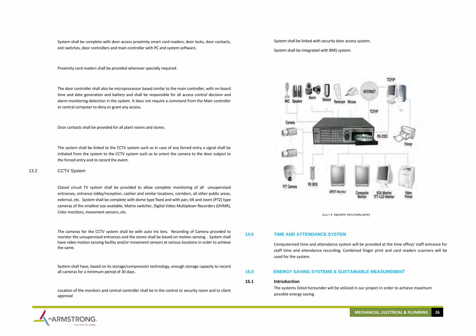
MECHANICAL, ELECTRICAL & PLUMBING 26
System shall be complete with door access proximity smart card readers, door locks, door contacts, exit switches, door controllers and main controller with PC and system software.
Proximity card readers shall be provided wherever specially required.
The door controller shall also be microprocessor based similar to the main controller, with on‐board time and date generation and battery and shall be responsible for all access control decision and alarm monitoring detection in the system. It does not require a command from the Main controller or central computer to deny or grant any access.
Door contacts shall be provided for all plant rooms and stores.
The system shall be linked to the CCTV system such as in case of any forced entry a signal shall be initiated from the system to the CCTV system such as to orient the camera to the door subject to the forced entry and to record the event.
13.2 CCTV System
Closed circuit TV system shall be provided to allow complete monitoring of all unsupervised entrances, entrance lobby/reception, cashier and similar locations, corridors, all other public areas, external, etc. System shall be complete with dome type fixed and with pan, tilt and zoom (PTZ) type cameras of the smallest size available, Matrix switcher, Digital Video Multiplexer Recorders (DVMR), Color monitors, movement sensors, etc.
The cameras for the CCTV system shall be with auto Iris lens. Recording of Camera provided to monitor the unsupervised entrances and the stores shall be based on motion sensing. . System shall have video motion sensing facility and/or movement sensors at various locations in order to achieve the same.
System shall have, based on its storage/compression technology, enough storage capacity to record all cameras for a minimum period of 30 days.
Location of the monitors and central controller shall be in the control or security room and to client approval
System shall be linked with security door access system.
System shall be integrated with BMS system.
(CCTV System Architecture)
14.0 TIME AND ATTENDANCE SYSTEM
Computerized time and attendance system will be provided at the time office/ staff entrance for staff time and attendance recording. Combined finger print and card readers scanners will be used for the system.
15.0 ENERGY SAVING SYSTEMS & SUSTAINABLE MEASUREMENT
15.1 Introduction The systems listed hereunder will be utilized in our project in order to achieve maximum possible energy saving.
MECHANICAL, ELECTRICAL & PLUMBING 27
1. Heat recovery units 2. Water supply pumps with VFD 3. Glass thermal properties and external walls construction details 4. Building management system 5. Thermal control and zoning 6. Power factor correction 7. Lighting control system 8. Energy saving lamps 9. Electronic ballasts
15.3 Heat Recovery Units The central extract system risers from toilets and general areas shall be discharging cold/hot air with different temperature related to every season.
Heat recovery sections comprising thermal wheel shall be added to the FAHUs to exchange cooling/heating from the extract air duct risers, which leads to increasing/reducing the temperature on the heating/cooling coil of FAHU.
A significant amount of cooling/heating can be retrieved by this unit, thereby reducing the cooling/heating load on chillers /boilers and electrical power consumptions accordingly.
15.4 Water Supply Pumps with VFD Main booster water pumps will be equipped with negotiable speed drives and shall be employed to supply water to the entire facility.
These pumps will supply varying amount of water proportional to the demand dictated by the project. Therefore at a time of low demand these pumps shall not work on full capacity and thus reduce electrical consumption.
15.5 Glass thermal properties and external walls construction details We recommend the use of high performance double glazing for all floors and thermal insulated external walls for the entire building. This will help in reducing the cooling/heating load as well as in reduction of noise transmission.
15.6 Building Management System (BMS) Introducing BMS for the building will result in significant energy saving by switching off all unnecessary loads
15.7 Thermal Control and Zoning The design will allow individual users to control air supply rates, air temperatures and humidity (for some specific areas) which will allow a reduction in load requirement during partial/no‐occupancy hours.
15.8 Power Factor Correction
Utilization of power factor correction system will result in a huge reduction of the reactive power as described hereunder:
Total connected load = (X) KW
S = Apparent Power = (X) KW
P = Active Power = S cos Ø
Q = Reactive Power = S sin Ø
COS Ø1 = Uncorrected power factor = 0.8
COS Ø2 = Corrected power factor = 0.93
Estimated reactive power saving = 7.5 %
15.9 Lighting Control System
The most intelligent lighting control system will be utilized and will be based on occupancy sensors, timers and photo cells. By utilizing this system all unnecessary luminaires will be switched off and accordingly a saving of 20% in energy consumption for lighting will be achieved.
15.10 Energy Saving Lamps
Utilizing T5 lamps instead of T8 lamps will result in higher illumination with less energy consumption. The calculated energy saving for utilizing T5 lamps is equal to 20% of the total fluorescent lamps energy.
15.11 Electronic Ballasts

MECHANICAL, ELECTRICAL & PLUMBING 28
All luminaires in air conditioned areas will be provided with electronic ballasts to reduce energy consumption of lamps and increase its life time.
16.0 STANDARD AND CODES
All work and materials used shall be in strict compliance with the applicable sections of the codes and standards, design guides issued by the following agencies:
ARI : American Refrigeration Institute
ASHRAE : American Society of Heating, Refrigerating & Air Conditioning Engineers Inc.
ASTM : American Society of Testing Materials
SMACNA : Sheet Metal and Air Conditioning Contractors National Association.
CIBSE : Chartered Institution of Building Services Engineers.
NFPA : National Fire Protection Association.
UL : Under writers Laboratory.
BS : British Standards Institution
IEE : Institution of Electrical Engineers.
IEC : International Electro ‐ technical Commission.
ISO : International Organization of Standardization.
ADDC : Abu Dhabi Distribution Company.
ADCD : Civil Defence Authority of Abu Dhabi.
ETISALAT : Telecom Company
: The Institute of Plumbing, UK
‐ End of Report ‐
I N T E R I O R D E S I G N 1
I N T E R I O R D E S I G N
INTRODUCTION MOOD IMAGES
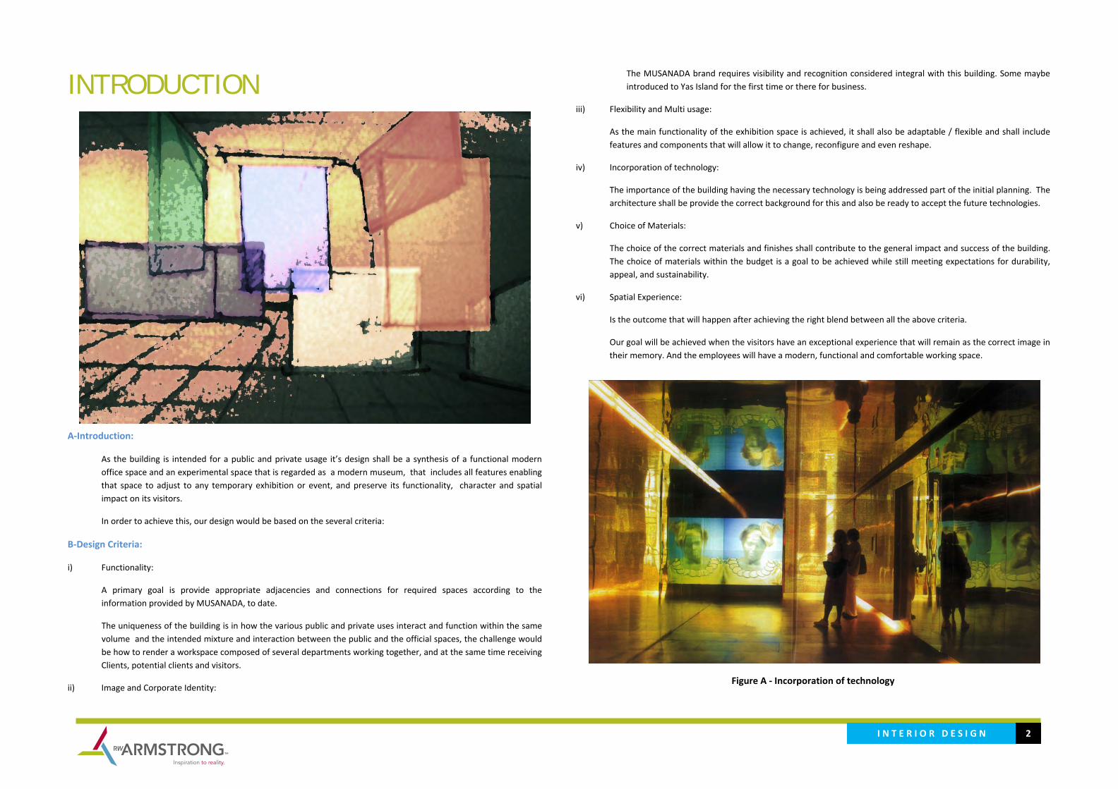
I N T E R I O R D E S I G N 2
INTRODUCTION
A‐Introduction:
As the building is intended for a public and private usage it’s design shall be a synthesis of a functional modern office space and an experimental space that is regarded as a modern museum, that includes all features enabling that space to adjust to any temporary exhibition or event, and preserve its functionality, character and spatial impact on its visitors.
In order to achieve this, our design would be based on the several criteria:
B‐Design Criteria:
i) Functionality:
A primary goal is provide appropriate adjacencies and connections for required spaces according to the information provided by MUSANADA, to date.
The uniqueness of the building is in how the various public and private uses interact and function within the same volume and the intended mixture and interaction between the public and the official spaces, the challenge would be how to render a workspace composed of several departments working together, and at the same time receiving Clients, potential clients and visitors.
ii) Image and Corporate Identity:
The MUSANADA brand requires visibility and recognition considered integral with this building. Some maybe introduced to Yas Island for the first time or there for business.
iii) Flexibility and Multi usage:
As the main functionality of the exhibition space is achieved, it shall also be adaptable / flexible and shall include features and components that will allow it to change, reconfigure and even reshape.
iv) Incorporation of technology:
The importance of the building having the necessary technology is being addressed part of the initial planning. The architecture shall be provide the correct background for this and also be ready to accept the future technologies.
v) Choice of Materials:
The choice of the correct materials and finishes shall contribute to the general impact and success of the building. The choice of materials within the budget is a goal to be achieved while still meeting expectations for durability, appeal, and sustainability.
vi) Spatial Experience:
Is the outcome that will happen after achieving the right blend between all the above criteria.
Our goal will be achieved when the visitors have an exceptional experience that will remain as the correct image in their memory. And the employees will have a modern, functional and comfortable working space.
Figure A ‐ Incorporation of technology
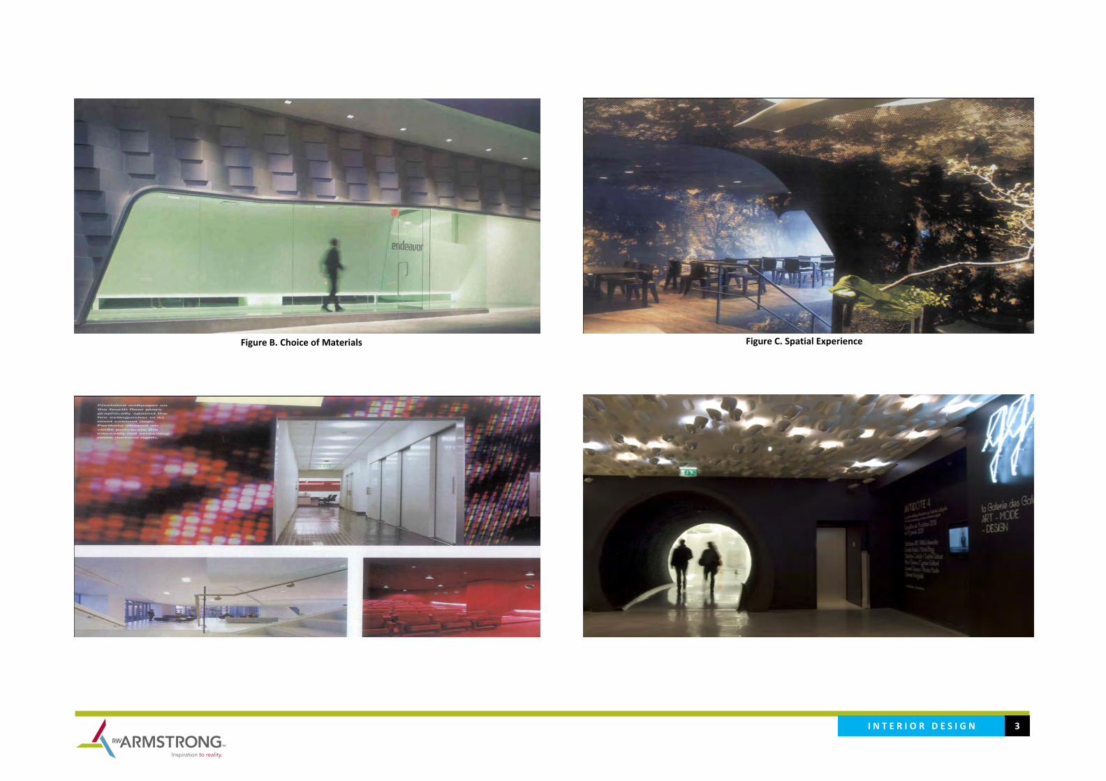
I N T E R I O R D E S I G N 3
Figure B. Choice of Materials
Figure C. Spatial Experience
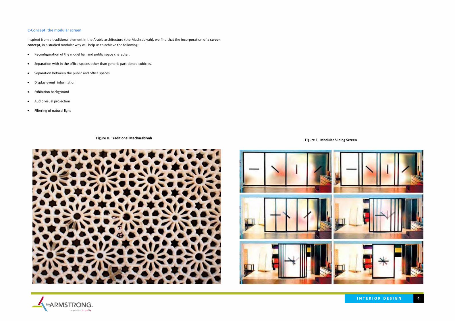
I N T E R I O R D E S I G N 4
C‐Concept: the modular screen
Inspired from a traditional element in the Arabic architecture (the Machrabiyah), we find that the incorporation of a screen concept, in a studied modular way will help us to achieve the following:
• Reconfiguration of the model hall and public space character.
• Separation with in the office spaces other than generic partitioned cubicles.
• Separation between the public and office spaces.
• Display event information
• Exhibition background
• Audio visual projection
• Filtering of natural light
Figure D. Traditional Macharabiyah
Figure E. Modular Sliding Screen

I N T E R I O R D E S I G N 5
Figure I. Guest Meeting Spaces (divided with screens rather than walls)
Figure F. Exhibition Space (Gridded Screen System for exhibition)
Figure G. Exhibition Space (separation from office area, filtering natural light)
Figure H. Office Space (separation: Stations and enclosed offices, ceiling‐wall treatment)
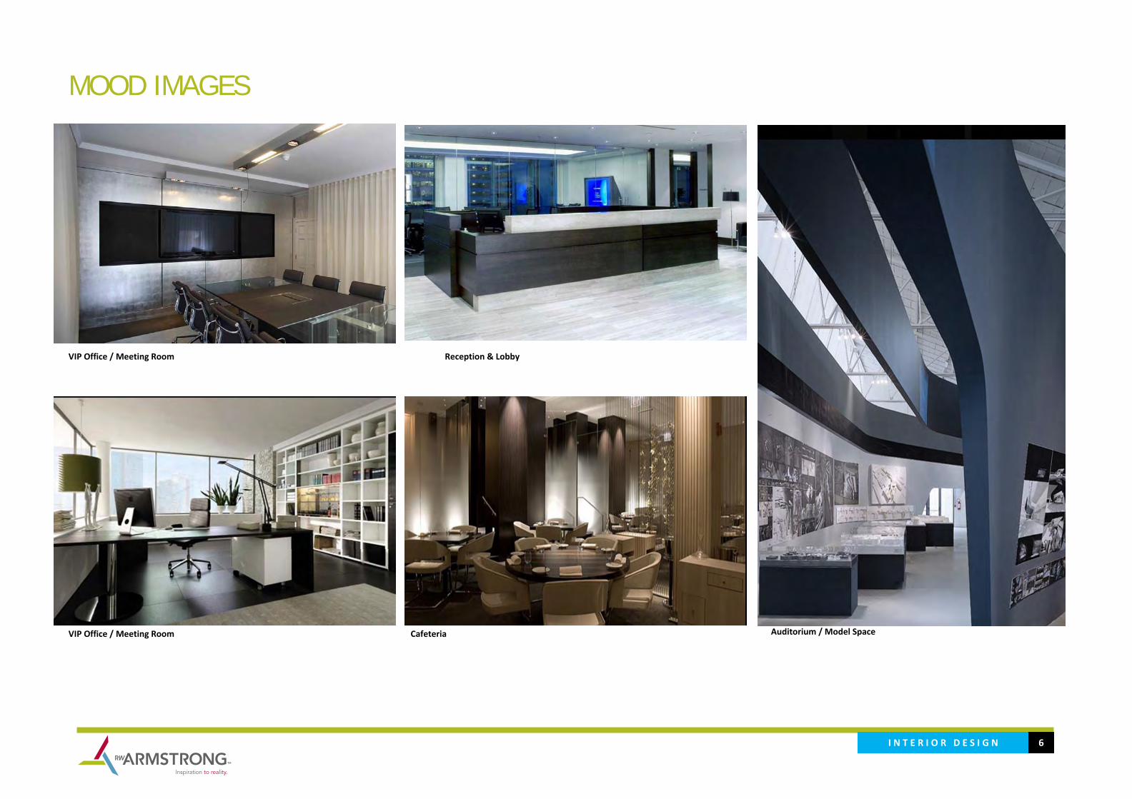
I N T E R I O R D E S I G N 6
MOOD IMAGES
VIP Office / Meeting Room Reception & Lobby
VIP Office / Meeting Room Cafeteria
Auditorium / Model Space
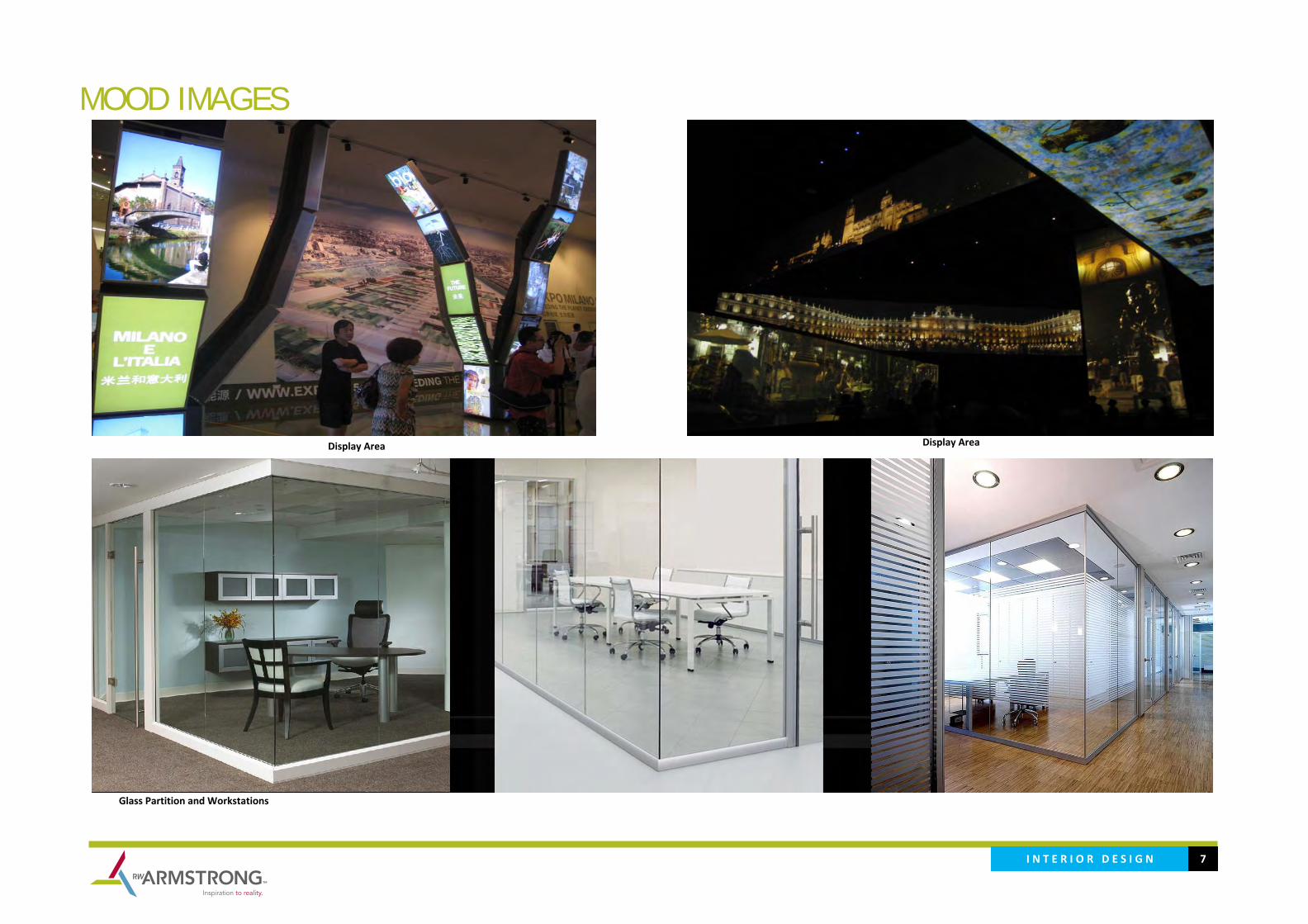
I N T E R I O R D E S I G N 7
MOOD IMAGES
Display Area
Glass Partition and Workstations
Display Area
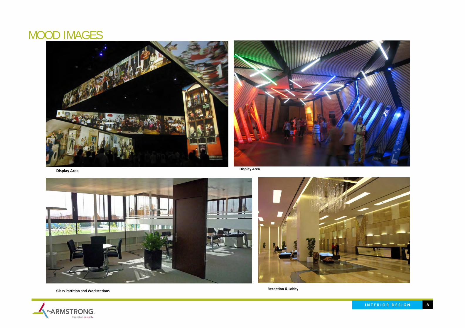
I N T E R I O R D E S I G N 8
MOOD IMAGES
Display Area
Glass Partition and Workstations
Display Area
Reception & Lobby
S U S T A I N A B I L I T Y 1
S U S T A I N A B I L I T Y

S U S T A I N A B I L I T Y 2
INTRODUCTION A‐Introduction:
Environmental impact of Buildings
According to the UAE Minister of Public Work the baseline benchmark referring at energy: 300kWh /sqm annually and water: 500 liter per person per day. The U.S. Department of Energy data book – October 2009, commercial building in the United States indirectly contribute 18%, or 6 billion metric tons, of the nation’s dioxide (Co2) emission through the consumption of energy, and consume 35.8% of all electricity generated in the United State. More than 50% of this electricity is derived from carbon –intense energy sources, such as coal and petroleum. Built a green building is not only mandatory by law but is an opportunity to positively impact the environment and meet the requirement of the RFP. The Owner is receptive to implementing measures that will positively impact them and will appreciate that you have educated them about green options
Commitment to sustainability
The process of integrating Estidama principal into property management is not always a linear journey. There are multiple entry point, and most owners and operators will have already start on many of the task outlined propose in this proposal. Regarding of where one begins, there are several consistent element to achieve success, beginning with making a commitment.
Changing the manner in which commercial property is operated does not need to be complex, but it has to start with commitment from stakeholders. Building Managers and owners must be committed to adopting sustainable practices and incorporating sustainability into their decision making. Many measures and policy changes can help transform a building’s operation, but without a commitment, these actions will not necessarily deliver the intended results. Greening a new building does not always demand a significant capital investment, but it does require the desire to find solution and willingness to measure efforts.
Greening Process.
There are five areas in which building can be greened:
‐ Energy‐saving ‐ Potable water reduction and water conserving initiatives ‐ Health ‐ Safety ‐ Indoor and outdoor environmental quality
In order successfully pursue Estidama Pearl Rating System PBRS certification, proper preparation and visioning is critical before commencing. Without buy‐in from of the involved parties, the creation of committed team, and proper financial planning, projects run the risk of falling short on their certification goals. Estidama Vision Abu Dhabi's Plan 2030 establishes a clear vision for sustainability as the foundation of any new development occurring in the Emirate and capital city of Abu Dhabi. This commitment is a reflection of the values and ideals of our nation. The tenets
of sustainable living in the Middle East are the guiding force behind Estidama. More than just a sustainability program, Estidama is the symbol of an inspired vision for governance and community development. The ESTIDAMA certification system is a flexible framework that allows project teams to decide which sustainable strategies to pursue based on the specifics of a particular project. ESTIDAMA requires all projects to meet certain prerequisites, and project teams choose which optional credits to pursue for additional points toward certification.
Method Statement for the Estidama Services RW Armstrong Sustainability Team will collect the data and develop strategy for sustainable, green building technologies and energy efficiency for ADAA headquarters. To provide the best sustainability intent in the cost effective way to achieve tree pearl required from the client. RW Armstrong as Sustainability Team will refer as guideline on the ESTIDAMA Building Perl Rating System (PBRD ver. 1) developed by Abu Dhabi Urban Planning Council (UPC).
After the data collection RW Armstrong Sustainability Team will consolidate the “Estidama strategy” and necessary report necessaries for the UPC preliminary design review for the New Headquarter for Abu Dhabi Accountability Authority (ADAA) Project.
The final result of the consolidation we will a list of achievable credit/recommendation to achieve the main target of the project.
The Consultant will must follow the ESTIDAMA Review Process of Abu Dhabi UPC and the framework. The Design team will be assisted in all the stage of the project to comply with: credit intent, credit requirement, and calculation methodology and should use all the reference included in the Rating System Sheet during the design stage. RW Armstrong Sustainability Team will provide the required document that will show the effective compliance with the credit requirement split in the 7 project stage.
Stage 1 – Concept design Stage 2 Schematic Design Stage 3 – Design Development Stage 4 – Tender/Construction Document Stage 5 – Tender services Stage 6 – Construction Supervision Stage 7 – Project Close out RW Armstrong Sustainability Team will assist the design team in all the project stage, in coordination and the implementation of an Integrated Design Process. The integrated project delivery will be maintain with interact keck‐off meeting, a program workshop and other workshop spitted in all the project stage. Regular weekly and bi‐weekly meeting

S U S T A I N A B I L I T Y 3
RW Armstrong Sustainability Team will assist the Design Team to develop a holistic concerted concept in order to considerably improve the energy efficiency, sustainability and living quality of the building. RW Armstrong Sustainability Team will develop in the Estidama Concept Report, the best strategy in order to provide a cooling building strategy. The Sustainability Team will support the Landscape architect to create an interconnected network of open spaces, differing in size, character and purpose to support a variety of human activities and natural systems, in order to increase the permeability of the building and create and improve the active urban environments of the area with less urban heat reduction. All the consideration will demonstrate and commented with the utilization of tools (Autodesk Ecotect Analysis and SunPath), and develop inside of the Sustainability Concept Report:
‐ Commented Bio‐Climatic Analysis: ‐ Climatic Analysis (latitude, climatic data, solar radiation, local specific condition of prevalent winds) ‐ Natural input (orientation and morphology) ‐ Dynamic shadows Analysis ‐ Orientation and shadow analysis ‐ Outdoor Thermal Comfort Strategy ‐ Thermal analysis Study ‐ Passive housing strategy and calculation ‐ Cool Building passive strategy ‐ PBRS Energy calculation ‐ PBRS Water Calculation ‐ PBRS Waste Calculation ‐ Selection of plant strategy for landscape or xeriscaping
RW Armstrong Sustainability Team will assist the MEP Team to develop and optimize and integrate a comprehensive water strategy during the early stage of design with the goal of minimizing the overall water consumption and establishing a project water balance. The Sustainability Team will also recommend the MEP Design Team to reduce the potable water use in exterior water features by minimizing evaporative loss and through the use of recycled water for achieve the target of 20% base on the ESTIDAMA PBRS water Calculator ver. 1.2. Will also help the MEP Design Team to recued the energy consumption and carbon emission associated with lighting and reduce peak electricity demand and increase efficiency in order to achieve the target of 45% of reduction base on ASHRAE 90.1.2007
Estidama Strategy for ADAA This ESTIDAMA approach to integrate the various design elements, in order to reach a Sustainable Green Building Design included in the Client’s vision for the Abu Dhabi Accountability Authority (ADAA) Project
The client vision related to the sustainability is to achieve Estidama 3 pearl according to the PBRS that mean achieve all mandatory credits plus 85 credit point The main design considering the following criteria:
‐ Reduce impact on the environment by proper selection of construction materials ‐ Design energy efficient building ‐ Create and maintain a healthy and natural environment ‐ Provide the residents‐users controls on their comfort ‐ Enhance natural lighting (day lighting) ‐ Waste Management and recycling. ‐ Integration to surrounding urban networks The building will be designed in a way to operate and serve to achieve luxury level of 5 star hotel the expected not ordinary comfort in compare to in similar projects, while minimizing energy and resources usage. Various systems and components
are to be coordinated to provide the maximum energy usage efficiency under the buildings’ operating and budgetary constraints alongside with provision of thermal comfort and enhanced and monitored indoor air quality.
In addition, the sustainable design will also cover the construction and the operating phases of the Project. In the Construction phase, controlling construction waste and emissions, using environmental friendly and renewable materials, and minimizing construction and equipping induced environmental effects. During the Operational phase, the aim is to mitigate the Project’s impacts on its surroundings, by reducing both its energy usage and waste production.
ESTIDAMA‐based Sustainable Design Basic Concepts For the purpose of the Abu Dhabi Accountability Authority (ADAA) Project, a set of basic design concepts are defined earlier in this phase. They constitute the Sustainability Basis of Design of the ADAA project, addressing architectural and structural aspects, as well as the HVAC and electrical utilities and services.
These basic design concepts fall under seven major categories:
• IDP ‐ Integration Development Process • NS ‐ Natural System • LBo ‐ Livable Building: Outdoor • LBi ‐ Livable Building: Indoors • PW ‐ Precious Water • RE ‐Resourceful Energy • SM‐ Stewarding Materials
It is worth defining in this ESTIDAMA Proposal report these basic design concepts as follows:
IDP – Integration Development Process An essential part of the strategy for achieving Estidama is to fundamentally change the way we approach design, construction. The Integration Development process calls for cross‐disciplinary teamwork and builds upon sound thinking, delivery quality and environmental management through the life of the project. This approach requires an integrated design approach from very early on in the design a clear vision and sustainability targets and implementation strategy.
The strategy to achieve the requirement past by:

S U S T A I N A B I L I T Y 4
The forecast Estidama achievable credit related to this Pearls Building Rating System section will include:
1. Develop and maintain an Life Cycle Cost (LCC) analysis from the concept design by a qualified professional, to evaluate and compare various design option throughout the design stage in option appraisals
2. Develop an Guest Worker Accommodation Plan with the contractor to promote fair labor practices in building construction
3. Develop with the contractor the Construction Environmental Management Plan (CEMP)
NS – Natural System Fundamental of the Abu Dhabi Plan 2030 is the need to foster careful, sensitive growth that will conserve, preserve, and restore the region’s critical natural environments and habitats. Plan 2030 concept is to create a green gradient that design an adequate level of conservation, prevention and restoration and propone an open space framework, a system of formal and informal spaces to implementing leading to healthier ecosystem, habitat and ultimately communities.
The intent of this credit section is intended to encourage natural resource management and sustainable land use trough:
The forecast Estidama achievable credit related to this Pearls Building Rating System section will include:
1. Enhance the ecological value of the site by planting native or adoptive species
LBo – Livable Building: Outdoors In order to be considered truly sustainable, new development must go beyond the environment to address the other three pillars of Estidama: Social, Cultural and Economic. This requires consideration of issues such as increased mobility and access to community facilities and connectivity and comfort of the public realm to encourage increased pedestrian activity. Our ultimate goal is to create a cohesive, contemporary and sustainable urban fabric for this new city and prosper as an attractive, livable place that preserves the emirate’s unique culture and environment.
The forecast Estidama achievable credit related to this Pearls Building Rating System section will include:
1. Increase outdoor thermal comfort during transition months and reduce thermal discomfort during summer months in public spaces and walkways
2. Encourage active lifestyle by providing building occupants and users with recreational public open space 3. Encourage the reduction of night time light pollution and its associated impact on human and ecological health.
LBi – Livable Building: Indoors Further research suggests that Green Building with improved indoor environmental quality can reduce the number of work days lost to sick leave by approximately three day per person per annum. Similarly, an increase of almost 5% in productivity has been attributed to healthier indoor environments. In order to creating a ‘livable indoors’ the new development buildings that address the challenges of improving occupant health and wellbeing whilst fostering economic growth anticipate from productivity gains, staff redemption and reduced absenteeism.
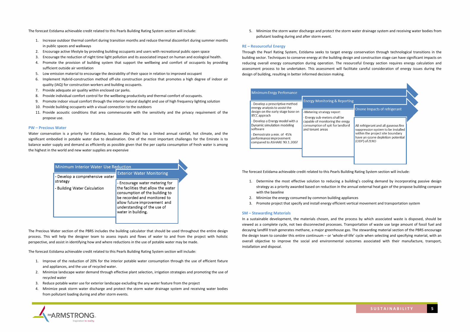
S U S T A I N A B I L I T Y 5
The forecast Estidama achievable credit related to this Pearls Building Rating System section will include:
1. Increase outdoor thermal comfort during transition months and reduce thermal discomfort during summer months in public spaces and walkways
2. Encourage active lifestyle by providing building occupants and users with recreational public open space 3. Encourage the reduction of night time light pollution and its associated impact on human and ecological health. 4. Promote the provision of building system that support the wellbeing and comfort of occupants by providing
sufficient outside air ventilation 5. Low emission material to encourage the desirability of their space in relation to improved occupant 6. Implement Hybrid‐construction method off‐site construction practice that promotes a high degree of indoor air
quality (IAQ) for construction workers and building occupants. 7. Provide adequate air quality within enclosed car parks. 8. Provide individual comfort control for the wellbeing productivity and thermal comfort of occupants. 9. Promote indoor visual comfort through the interior natural daylight and use of high frequency lighting solution 10. Provide building occupants with a visual connection to the outdoors 11. Provide acoustic conditions that area commensurate with the sensitivity and the privacy requirement of the
propose use.
PW – Precious Water Water conservation is a priority for Estidama, because Abu Dhabi has a limited annual rainfall, hot climate, and the significant embodied in potable water due to desalination. One of the most important challenges for the Emirate is to balance water supply and demand as efficiently as possible given that the per capita consumption of fresh water is among the highest in the world and new water supplies are expensive
The Precious Water section of the PBRS includes the building calculator that should be used throughout the entire design process. This will help the designer team to assess inputs and flows of water to and from the project with holistic perspective, and assist in identifying how and where reductions in the use of potable water may be made.
The forecast Estidama achievable credit related to this Pearls Building Rating System section will include:
1. Improve of the reduction of 20% for the interior potable water consumption through the use of efficient fixture and appliances, and the use of recycled water.
2. Minimize landscape water demand through effective plant selection, irrigation strategies and promoting the use of recycled water
3. Reduce potable water use for exterior landscape excluding the any water feature from the project 4. Minimize peak storm water discharge and protect the storm water drainage system and receiving water bodies
from pollutant loading during and after storm events.
5. Minimize the storm water discharge and protect the storm water drainage system and receiving water bodies from pollutant loading during and after storm event.
RE – Resourceful Energy Through the Pearl Rating System, Estidama seeks to target energy conservation through technological transitions in the building sector. Techniques to conserve energy at the building design and construction stage can have significant impacts on reducing overall energy consumption during operation. The resourceful Energy section requires energy calculation and assessment process to be undertaken. This assessment will facilitate careful consideration of energy issues during the design of building, resulting in better informed decision making.
The forecast Estidama achievable credit related to this Pearls Building Rating System section will include:
1. Determine the most effective solution to reducing a building’s cooling demand by incorporating passive design strategy as a priority awarded based on reduction in the annual external heat gain of the propose building compare with the baseline
2. Minimize the energy consumed by common building appliances 3. Promote project that specify and install energy efficient vertical movement and transportation system
SM – Stewarding Materials In a sustainable development, the materials chosen, and the process by which associated waste is disposed, should be viewed as a complete cycle, not two disconnected processes. Transportation of waste use large amount of fossil fuel and decaying landfill trash generates methane, a major greenhouse gas. The stewarding material section of the PBRS encourage the design team to consider this entire continuum – or ‘whole‐of‐life’ cycle when selecting and specifying material, with an overall objective to improve the social and environmental outcomes associated with their manufacture, transport, installation and disposal.

S U S T A I N A B I L I T Y 6
The forecast Estidama achievable credit related to this Pearls Building Rating System section will include:
1. Promote selection of material that do not have long term negative impact on human health or pollute natural systems
2. Lengthen the useful life of building through design that is easily adaptable for other program uses. 3. Facilitate the future deconstruction and reuse of building and their structure and envelope components 4. Minimize waste associated with replacement of flooring system through the use of modular system 5. Encourage the use of timber sourced from legal and sustainable sources
Process
Team Structure Criteria:
‐ Included Building Operator ‐ Include LCC consultant ‐ Include Contractor or Construction Manager ‐ Environmental Engineer ‐ Include Landscape consultant ‐ Include Acoustic Engineer
‐ Include Sustainability Team Building Design Criteria:
1. Utilize a Unitized System instead Stick System for the façade 2. Primary and Secondary Pedestrian walkway 85% Shadow calculated at 1:00 pm clock time on equinox (20 March or
20 September) and summer solstice (21 June) 3. Surface car Parking 55% shadow calculated at 1:00 pm clock time on equinox (20 March or 20 September) and
summer solstice (21 June) 4. Include Landscape Area for recreation 5. Smoking Area: Establish 25 smoke free zone around the entrance
Provide no smoking signage in the building and in the basement 6. All internal construction material meet formaldehyde VOC content class E1 level 7. Hybrid‐Construction Method: Our proposal is to construct these buildings using a Hybrid style construction
comprising part traditional in‐situ construction and part modular construction off‐site. HYBRID construction looks at constructing the core utilizing traditional construction methods such as reinforced concrete cast in‐situ. The principal behind the modular method of construction is that the individual modules will be able to support the axial load from the modules stacked on top. The horizontal restraint, required to stabilize the structure will come from the modules being tied into the inner core of the buildings.
8. Glade Control Devices Automated controlled internal glade control devices for all the windows 9. Natural daylight shall be guarantee of 250 lux on the working plan (762 mm from FFL) for a 75% of the occupied
area calculated based on a CIE standard clear sky at 10am, 12pm, and 2pm on the equinox and summer solstice excluding contribution from any artificial light
10. View 75% of all occupied area have a direct line of sight to the outside through vision glazing Vision Glazing includes those windows within the vision area of 762 mm to 2286 mm height from FFL and excludes any frame area. Seated Head Height is 1.1 m from FFL.
11. Noise Pollution All internal ambient noise level not exceed 50 dB (A) Leq in the area to be occupied 12. Energy efficient appliances All installed appliances shall be and that tenant guideline outlines the benefit of energy
efficient appliances will be produced 13. Staircase visible. Develop a vertical distribution system that will make easily accessible stairs to at least the first
three floors, and that the stairs are either visible from the main entrance or visible from the main building lift. The stairs shall be open or visible at least one side
14. Energy Efficient Lift – included regenerative drive system and LED lighting and LCD display features 15. Energy Efficient escalator – Offer an automated stop/start function linked to occupancy sensor to enable standby
mode when is no passenger demand and LED strip lighting
Structural Design Criteria 1. Hybrid‐Construction Method: Our proposal is to construct these buildings using a Hybrid style construction
comprising part traditional in‐situ construction and part modular construction off‐site. HYBRID construction looks at constructing the core utilizing traditional construction methods such as reinforced concrete cast in‐situ. The principal behind the modular method of construction is that the individual modules will be able to support the axial load from the modules stacked on top. The horizontal restraint, required to stabilize the structure will come from the modules being tied into the inner core of the buildings.
Infrastructural Design Criteria:
1. Develop a storm water management plan:

S U S T A I N A B I L I T Y 7
Storm water calculation shall be demonstrate that the post‐development peak runoff rate and quantity from the 2 year 24 hour design storm does not exceed the pre development peak run‐off rate and quantity through structural method or a combination of both structural and nonstructural methods. The propose management system is capable of collecting and treating a minimum of 90% of storm water and that the treatment process in capable of achieving the following minimum standard for quality control: 80% removal of Total Suspended Solids (TSS), Min. 95% removal of litter (gross pollutants, >1mm, min. 90% removal of hydrocarbons, use of petrol interceptors or suitable permeable paving for car parks for more than 4.
Landscape Design Criteria:
2. Plants selection: 70% of the plants specified for planting on the site to comprise native and adoptive drought and/or saline tolerant species including a minimum of 10 different of species.
3. Irrigation. incorporated into the landscape design a Water efficient irrigation system and operational and maintenance plan with an average of irrigation demand < 4 liter / m2 / day
4. Outdoor Thermal Comfort: Public Open Space 70% of shadow Primary and Secondary Pedestrian walkway 85% Shadow Cycle Tracks 65% shadow Surface Car Parking 55%
5. Include Landscape Area for recreation 6. Light Pollution: All not safety and security external lighting, including display, advertising and specially lighting,
must be automatically switched off between 23:00 hrs. And 7:00 hrs. 7. Smoking Area: Establish 25m smoke free zone around the entrance
Provide dedicate external smoking areas away from public or high use pedestrian 8. No water feature included in the project 9. Hard Landscape: Paving – Porosity of the paving for all the external hard landscape that will prioritize infiltration,
sustainable urban drainage system
MEP Design Criteria:
1. Electrical: Interior Lighting: The project it’s classified under IECC 2009 Zones as LZ3 for this reason should follow the following requirement:
Lighting Zone Max. initial Illuminance at
site boundary LUX Max Initial Illuminance at specified Distance beyond Site Boundary LUX
Max % Uplight
LZ3 2.2 <1 at 4.5 meters 5%
The angle of maximum candela from each interior luminaire, as positioned in the building, must not exit throng the windows. Alternatively, all non‐ emergency interior lighting must be controlled to automatically turn off outside the normal hours of occupancy. Manual override must be enabled to allow for any out‐for‐hour use. Reference standard IESNA RP‐33‐99 and IES RP‐8 No incandescent lamps may be installed in the internal environment and for all permanently installed fluorescent lighting installations must incorporate high frequency electronic ballasts. Occupancy sensor in all rooms intended for individual occupancy, conferencing or meeting rooms, open plan office space and hallways or corridor Install Daylight sensor to light fitting that receive sufficient daylight illuminance Automated glade control devices must be connected to the building management system
Natural daylight shall be guarantee of 250 lux on the working plan (762 mm from FFL) for a 75% of the occupied area calculated based on a CIE standard clear sky at 10am, 12pm, and 2pm on the equinox and summer solstice excluding contribution from any artificial light Energy Efficient Appliances all installed appliances shall be energy efficient by energy star program, EU energy Efficiency label scheme Accessible stairs Achieve min. light level of 150 lux measured at the walking surfaces and the artificial light used within the stair must be supplied with color corrected lamps with provide a minimum CRI of 80
Mechanical Ventilation and HVAC: Thermal Comfort ‐ Design for separate zones and control for maximum of 35m2 of opens space on the perimeter of the building and maximum 70 m2 of open space plan in the internal areas of the building ‐ Each thermal zone must have thermostat that allow control over air speed or temperature as a minimum ‐ Single office, or office with two occupants, must have one thermostatic controller must be provided that allows control over air speed or temperature as a minimum. ‐ Multi‐occupant space (meeting room, conference hall) must at least have one thermostatic controller.
Ventilation: ‐ Increase the air ventilation of 15% above the outdoor air ventilation as per standard ASHRAE 62.1.2007 ‐ Provide occupant sensor linked to HVAC system that automatically modulate temperature and air flow rate based on occupancy down to a minimum design setback in all multi‐occupant space ‐ Install Permanent Carbon Dioxide (CO2) monitoring and alert system to ensure the adequate provision of outside air at all times. At minimum, one CO2 sensor must installed at each return point. The CO2 level must not be allowed to exceed 1000ppm ‐ Car Park ventilation: The design meets or exceed requirement for pollutant concentration in car park of: Air Pollutant Averaging Time Maximum concentrationCarbon Monoxide (CO) 15 min. 100 mg/m3Nitrogen Dioxide (NO2) 1 hour 200 µg/m3Particular Matter PM10 24 hours 50 µg/m3
‐ Install air quality sensor ‐ Outdoor air intakes and outlets ‐ Air quality alert system ‐ BMS point schedules
2. Plumbing ‐ Legionella Management Plan and Implementation ‐ Water fixture baseline Flow rates Not Residential Fixtures Flow Rate Kitchen Taps 6 l/min @ 417.7 KPa Bathroom wash basin taps 1.9 l/min @ 417.7 KPa Toilet Dual Flush 6/4 l/min or l/use Urinals 0.5 l/flushing cycle Absolution Spray 6 l/min
‐ Water Meter Provide water Meter for: External hose bibs, Irrigation Systems, Bathroom / Toilet Facilities, Kitchen/Catering Facility.
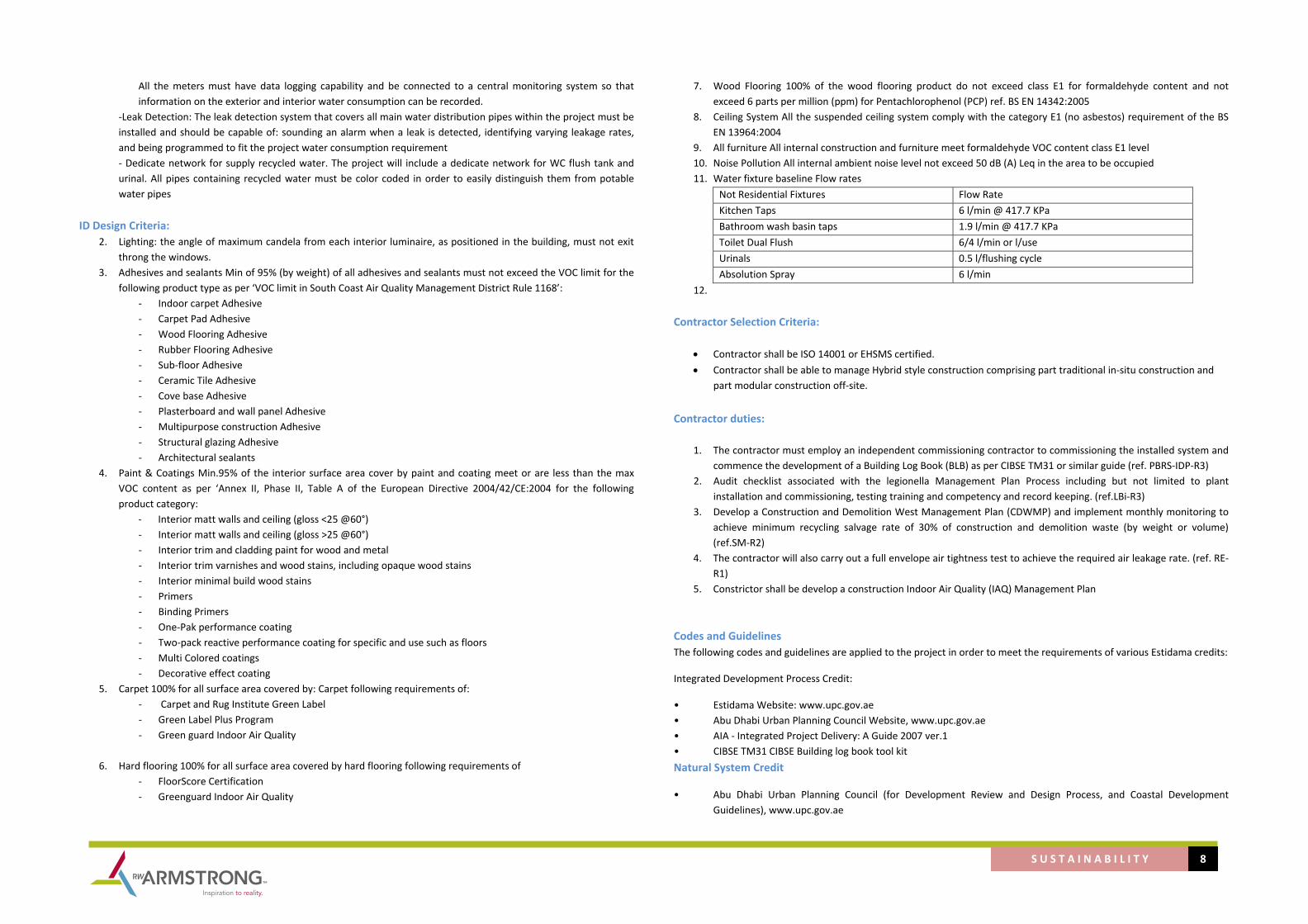
S U S T A I N A B I L I T Y 8
All the meters must have data logging capability and be connected to a central monitoring system so that information on the exterior and interior water consumption can be recorded.
‐Leak Detection: The leak detection system that covers all main water distribution pipes within the project must be installed and should be capable of: sounding an alarm when a leak is detected, identifying varying leakage rates, and being programmed to fit the project water consumption requirement ‐ Dedicate network for supply recycled water. The project will include a dedicate network for WC flush tank and urinal. All pipes containing recycled water must be color coded in order to easily distinguish them from potable water pipes
ID Design Criteria: 2. Lighting: the angle of maximum candela from each interior luminaire, as positioned in the building, must not exit
throng the windows. 3. Adhesives and sealants Min of 95% (by weight) of all adhesives and sealants must not exceed the VOC limit for the
following product type as per ‘VOC limit in South Coast Air Quality Management District Rule 1168’: ‐ Indoor carpet Adhesive ‐ Carpet Pad Adhesive ‐ Wood Flooring Adhesive ‐ Rubber Flooring Adhesive ‐ Sub‐floor Adhesive ‐ Ceramic Tile Adhesive ‐ Cove base Adhesive ‐ Plasterboard and wall panel Adhesive ‐ Multipurpose construction Adhesive ‐ Structural glazing Adhesive ‐ Architectural sealants
4. Paint & Coatings Min.95% of the interior surface area cover by paint and coating meet or are less than the max VOC content as per ‘Annex II, Phase II, Table A of the European Directive 2004/42/CE:2004 for the following product category:
‐ Interior matt walls and ceiling (gloss <25 @60°) ‐ Interior matt walls and ceiling (gloss >25 @60°) ‐ Interior trim and cladding paint for wood and metal ‐ Interior trim varnishes and wood stains, including opaque wood stains ‐ Interior minimal build wood stains ‐ Primers ‐ Binding Primers ‐ One‐Pak performance coating ‐ Two‐pack reactive performance coating for specific and use such as floors ‐ Multi Colored coatings ‐ Decorative effect coating
5. Carpet 100% for all surface area covered by: Carpet following requirements of: ‐ Carpet and Rug Institute Green Label ‐ Green Label Plus Program ‐ Green guard Indoor Air Quality
6. Hard flooring 100% for all surface area covered by hard flooring following requirements of
‐ FloorScore Certification ‐ Greenguard Indoor Air Quality
7. Wood Flooring 100% of the wood flooring product do not exceed class E1 for formaldehyde content and not exceed 6 parts per million (ppm) for Pentachlorophenol (PCP) ref. BS EN 14342:2005
8. Ceiling System All the suspended ceiling system comply with the category E1 (no asbestos) requirement of the BS EN 13964:2004
9. All furniture All internal construction and furniture meet formaldehyde VOC content class E1 level 10. Noise Pollution All internal ambient noise level not exceed 50 dB (A) Leq in the area to be occupied 11. Water fixture baseline Flow rates
Not Residential Fixtures Flow Rate Kitchen Taps 6 l/min @ 417.7 KPa Bathroom wash basin taps 1.9 l/min @ 417.7 KPa Toilet Dual Flush 6/4 l/min or l/use Urinals 0.5 l/flushing cycle Absolution Spray 6 l/min
12.
Contractor Selection Criteria:
• Contractor shall be ISO 14001 or EHSMS certified. • Contractor shall be able to manage Hybrid style construction comprising part traditional in‐situ construction and
part modular construction off‐site. Contractor duties:
1. The contractor must employ an independent commissioning contractor to commissioning the installed system and commence the development of a Building Log Book (BLB) as per CIBSE TM31 or similar guide (ref. PBRS‐IDP‐R3)
2. Audit checklist associated with the legionella Management Plan Process including but not limited to plant installation and commissioning, testing training and competency and record keeping. (ref.LBi‐R3)
3. Develop a Construction and Demolition West Management Plan (CDWMP) and implement monthly monitoring to achieve minimum recycling salvage rate of 30% of construction and demolition waste (by weight or volume) (ref.SM‐R2)
4. The contractor will also carry out a full envelope air tightness test to achieve the required air leakage rate. (ref. RE‐R1)
5. Constrictor shall be develop a construction Indoor Air Quality (IAQ) Management Plan
Codes and Guidelines The following codes and guidelines are applied to the project in order to meet the requirements of various Estidama credits:
Integrated Development Process Credit:
• Estidama Website: www.upc.gov.ae • Abu Dhabi Urban Planning Council Website, www.upc.gov.ae • AIA ‐ Integrated Project Delivery: A Guide 2007 ver.1 • CIBSE TM31 CIBSE Building log book tool kit Natural System Credit
• Abu Dhabi Urban Planning Council (for Development Review and Design Process, and Coastal Development Guidelines), www.upc.gov.ae
S U S T A I N A B I L I T Y 9
• Environment Agency Abu Dhabi (for Environmental Impact Assessment (EIA) and Preliminary Environmental Review (PER) guidelines), www.ead.ae
• Union for Conservation of Nature, IUCN, www.iucn.org • Wild Flowering Plants of the UAE, Environmental Research and Wildlife Development Agency, 2002 • Birds of Abu Dhabi – Checklist, Environmental Research and Wildlife Development Agency, July 2001 • Interpretation Manual of Major Terrestrial Natural and Semi‐natural habitat types of Abu Dhabi Emirate, Gary
Brown and Benno Boer, Environmental Research and Wildlife Development Agency, September 2004 • Red List of Terrestrial Mammalian Species of the Abu Dhabi Emirate, Environmental Research and Wildlife
Development Agency, May 2005 • The terrestrial mammals, reptiles and amphibians of the UAE – Species list and status report, Environmental
Research and Wildlife Development Agency, January 2005 • Terrestrial Environment of Abu Dhabi Emirate, Environment Agency Abu Dhabi, 2008, www.ead.ae • Handbook for Phase 1 Habitat Survey – a technique for environmental audit, JNCC, 2007, www.jncc.gov.uk • Vascular Plants of Abu Dhabi Emirate, Gary Brown and Sabitha Sakkir, August 2004
Livable Building Credit • Plan 2030 relevant to the site • Development Codes relevant to the site • Area Plans relevant to the site • Plan 2030 (Abu Dhabi, Al Ain, Western Region or Eastern Region) www.upc.gov.ae • "Abu Dhabi Urban Planning Council, Development Review Process • www.upc.gov.ae/en/DevelopmentReview/DevelopmentReviewProcess.aspx" • Abu Dhabi Urban Planning Council, Coastal Development Guidelines www.upc.gov.ae • ASTM E1980 ‐ 01 Standard Practice for Calculating Solar Reflectance Index of Horizontal and Low‐Sloped Opaque
Surfaces • ASTM E1918‐06, Standard Test Method for Measuring Solar Reflectance of Horizontal and Low‐Sloped Surfaces in
the Field • ASTM C1549‐09, Standard Test Method for Determination of Solar Reflectance near Ambient Temperature Using a
Portable Solar Reflectometer • ASTM E 408‐71(2008), Standard Test Methods for Total Normal Emittance of Surfaces Using Inspection‐Meter
Techniques • ASTM C1371‐04a, Standard Test Method for Determination of Emittance of Materials near Room Temperature
Using Portable Emissometers • Abu Dhabi Urban Street Design Manual • Community facilities requirements, Urban Planning Council • ASHRAE 62.1.2007 “Ventilation for Acceptable Indoor Air Quality”, www.ashrae.org • "‘Legionnaire’s Disease‐ The Control of Legionella Bacteria in Water Systems’, Approved Code of Practice and
Guidance (L8), 3rd Edition 2000, UK Health and Safety • Executive, www.hse.gov.uk" • "Control of Legionella bacteria in water systems: Audit Checklists, 2003, UK Health and • Safety Executive, www.hse.gov.uk" • SMACNA, IAQ Guidelines for Occupied Buildings under Construction
Precious Water Credit • Pearl Rating System Building Water Calculator
Resourceful Energy Credit
• "ASHRAE/ASHRAE/IESNA 90.1 – 2007: Energy Standard for Buildings Except Low‐Rise • Residential Buildings" • GIL 65: Metering Energy Use in New Non‐Domestic Buildings • CIBSE TM39 2009: Building Energy Metering • IECC 2009 – International Energy Conservation Code
Stewarding Material Credit
• "Cabinet Resolution No. 39 of 2006 Concerning Prohibiting Import, Production and • Utilization of Asbestos Boards" • ASTM E 2356‐04 ‐ Comprehensive Building Asbestos Surveys • Centre of Waste Management, Abu Dhabi: www.cwm.ae • Centre of Waste Management, Abu Dhabi: www.cwm.ae
General Green Building Code and Good Practice
• Local Erosion and Sedimentation Control Standards • Local Definition of Wetlands, Prime Agricultural Land, Brownfield Sites • National and Regional Endangered Species Lists • Local Guideline on Management for Source of Non‐Pollution in Coastal Waters • American Council for an Energy Efficient Economy (ACEEE) annual vehicle rating guide • ASTM E1903‐97 Phase II Environmental Site Assessment • ASTM E1980‐01 Standard Practice for Calculating Solar Reflectance Index • ASTM E408‐71 Standard Test Method for Total Normal Emittance • ASTM E903‐96 Solar Absorptance, Reflectance and Transmittance • ASTM E1918‐97 Solar Reflectance of Horizontal Surfaces • ASTM C1371‐04 Determination of Emittance of Materials near Room Temperature • ASTM C1549‐04 Determination of Solar Reflectance near Ambient Temperature • ASHRAE/IESNA 90.1‐2004 Energy Standard for Buildings except Low Rise Residential – Exterior Lighting Section9 • IESNA RP‐33 • The Energy Policy Act of 1992 • EPA Clean Air Cat, Title VI, Rule 608 Procedure Governing Refrigerant Management and Reporting • EPA List of Substitutes for Ozone‐depleting Substances • International Performance Measurement and Verification Protocol (IPMVP) Volume III • ISO 14021‐1999 Environmental Labels and Declarations • Forest Stewardship Council (FSC) Principles and Criteria • ANSIASTM E779‐03 Standard Test Method for Determining Air Leakage Rate • South Coast Air Quality Management District Rule No. 1168 regarding VOC limits for adhesives and sealants and
Rule No. 1113 regarding Architectural Paint • Green Seal Standard GS‐36 regarding VOC Limits for Commercial adhesives, GS‐11 regarding VOC Limits for
Commercial Paints, GS‐03 regarding VOC Limits for anti‐corrosive and anti‐rust paints and coatings • Carpet and Rug Institute Green Label Testing Program regarding VOC emission limits for carpets and carpet cushion • ASHRAE 55‐2007 Thermal Environmental Conditions for Human Occupancy

Pearl Building Rating System
Project Name New Headquarter for Abu Dhabi Accountability Authority (ADAA)
Project ID N/A
Building Use Office
Pearl Rating Stage Design
Pearl QP Name Antonio Ceci
Pearl QP Number N/A
Date
Credit Points Summary
Yes Maybe No Yes Maybe No
IDPIDP-R1 Integrated Development Strategy Required Integrated Design Process / stakeholder / Project Management
IDP-R2 Tenant Fit-Out Design & Construction Guide Required Not in the design stage
IDP-R3 Basic Commissioning Required Commissioning
IDP-1 Life Cycle Costing 4 4 Mona have experience
IDP-2 Guest Worker Accommodation 2 2 we have already document
IDP-3 Construction Environmental Management 2 2Construction Environmental Management Plan / Certified Contractor’s ISO
14001 or Abu Dhabi EHSMS certification
IDP-4 Building Envelope Verification 1 1 Curtain wall / Unitized Panel
IDP-5 Re-Commissioning 2 2
IDP-6 Sustainability Communication 2 2 Occupant Handbook / Occupant Feedback / Building Automation System BMS
TOTAL 13 13 0 0 0 0 0
NSNS-R1 Natural Systems Assessment Required Abu Dhabi Natural System Report
NS-R2 Natural Systems Protection Required Nothing to be protected
NS-R3 Natural Systems Design & Management Strategy Required Landscape strategy
NS-1 Reuse of Land 2 2 Impossible
NS-2 Remediation of Contaminated Land 2 2 Impossible
NS-3 Ecological Enhancement 2 2 10 different type of plant for saline environment
NS-4 Habitat Creation & Restoration 6 6
TOTAL 12 2 6 4 0 0 0
LBoLBo-R1 Plan 2030 Required Compliance with Plan 2030
LBo-R2 Urban Systems Assessment Required UPC Report
LBo-R3 Outdoor Thermal Comfort Strategy Required 40% Parking / 75% primary walkway
LBo-1 Improved Outdoor Thermal Comfort 2 2 55% Parking / 85% Primaey walkay - SRI 29
LBo-2 Pearl Rated Communities 1 1
LBo-3 Accessible Community Facilities 1 1 350 m facility to be check
LBo-4 Active Urban Environments 1 1 Landscape for recreation
Report a Template Bug : [email protected]
Yes
Yes
Yes
Yes
Yes
Yes
Project Details
ConstructionDesignCredit Title
Credit Points Available
Credit Reference
Yes
Yes
Comments
Integrated Development Process
Natural Systems
Livable Buildings : Outdoors
Yes

Pearl Building Rating System
Project Name New Headquarter for Abu Dhabi Accountability Authority (ADAA)
Project ID N/A
Building Use Office
Pearl Rating Stage Design
Pearl QP Name Antonio Ceci
Pearl QP Number N/A
Date
Credit Points Summary
Yes Maybe No Yes Maybe No
Report a Template Bug : [email protected]
Project Details
ConstructionDesignCredit Title
Credit Points Available
Credit Reference Comments
LBo-5 Private Outdoor Space n/a
LBo-6 Public Transport 3 3 bus stop or metro in 350 m
LBo-7 Bicycle Facilities 2 1 Shade park for bicycle long term 1 space for 500 mq 1space for shart
LBo-8 Preferred Car Parking Spaces 1 1 6% of parkign for electric car
LBo-9 Travel Plan 1 1
LBo-10 Light Pollution Reduction 1 1 light pollution
13 5 6 1 0 0 0
LBiLBi-R1 Healthy Ventilation Delivery Required
LBi-R2 Smoking Control Required
LBi-R3 Legionella Prevention Required
LBi-1 Ventilation Quality 3 3 (CO2) monitoring + 15 % more ventilation
LBi-2.1 Materials Emissions : Adhesives & Sealants 1 1 95% of all adhesives & sealants meet criteria
LBi-2.2 Materials Emissions : Paints & Coatings 1 1 95% of all surface areas meet criteria
LBi-2.3 Materials Emissions: Carpet & Hard Flooring 1 1 100% of all carpets, carpet cushion, hard flooring and associated
LBi-2.4 Materials Emissions : Ceiling Systems 1 1 no asbestos and formaldehyde
LBi-2.5 Materials Emissions : Formaldehyde Reduction 2 2 No formaldehyde class E1 levels material
LBi-3 Construction Indoor Air Quality Management 2 2 Hybrid Construction
LBi-4 Car Park Air Quality Management 1 1Carbon Monoxide (CO) 15 minutes 100 mg / m3
Nitrogen Dioxide (NO2) 1 hour 200 ��g/m3Particular Matter PM10 24 hours 50 ��g/m3
LBi-5.1 Thermal Comfort & Controls: Thermal Zoning 1 thermostatic controller for multipurpose room and max 35 mq thermal zone
LBi-5.2 Thermal Comfort & Controls: Occupant Control 2 2 1 control per space
LBi-5.3 Thermal Comfort & Controls: Thermal Comfort Modeling 2 2
LBi-6 High Frequency Lighting 1 1 No incandescent lamps -> LED
LBi-7 Daylight & Glare 2 2Home Automation BMS Demonstrate a minimum daylight illuminance of 250 Lux on
the working plane (762mm from finished floor level)
LBi-8 Views 1 1 75% od occupancy have wxternal view
LBi-9 Indoor Noise Pollution 1 1 internal ambient noise levels do not exceed 50 dB(A) Leq
LBi-10 Safe & Secure Environment 1 1 Safety & Security Risk Assessment / etc
23 19 3 0 0 0 0
Yes
Yes
Yes
SUB-TOTAL
SUB-TOTAL
Livable Buildings : Indoors
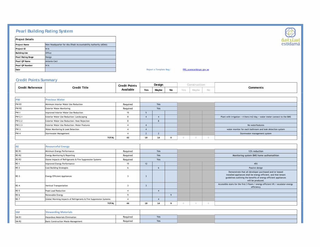
Pearl Building Rating System
Project Name New Headquarter for Abu Dhabi Accountability Authority (ADAA)
Project ID N/A
Building Use Office
Pearl Rating Stage Design
Pearl QP Name Antonio Ceci
Pearl QP Number N/A
Date
Credit Points Summary
Yes Maybe No Yes Maybe No
Report a Template Bug : [email protected]
Project Details
ConstructionDesignCredit Title
Credit Points Available
Credit Reference Comments
PWPW-R1 Minimum Interior Water Use Reduction Required
PW-R2 Exterior Water Monitoring Required
PW-1 Improved Interior Water Use Reduction 15 5
PW-2.1 Exterior Water Use Reduction: Landscaping 8 4 4 Plant with irrigation < 4 liters/m2/day + water meter connect to the BMS
PW-2.2 Exterior Water Use Reduction: Heat Rejection 8 8
PW-2.3 Exterior Water Use Reduction: Water Features 4 4 No waterfeatures
PW-3 Water Monitoring & Leak Detection 4 4 water monitor for each bathroom and leak detection system
PW-4 Stormwater Management 4 2 2 Stormwater management system
TOTAL 43 19 14 0 0 0 0
RERE-R1 Minimum Energy Performance Required 12% reduction
RE-R2 Energy Monitoring & Reporting Required Monitoring system BMS home authomathion
RE-R3 Ozone Impacts of Refrigerants & Fire Suppression Systems Required
RE-1 Improved Energy Performance 15 12 45%
RE-2 Cool Building Strategies 6 6 Passive design
RE-3 Energy Efficient Appliances 3 3
Demonstrate that all developer purchased and/or leasedinstalled appliances shall be energy efficient, and that tenantguidelines outlining the benefits of energy efficient appliances
will be produced.
RE-4 Vertical Transportation 3 3Accessible stairs for the first 3 floors / energy efficient lift / escalator energy
efficiency
RE-5 Peak Load Reduction 4 4
RE-6 Renewable Energy 9 9
RE-7 Global Warming Impacts of Refrigerants & Fire Suppression Systems 4 4
TOTAL 44 18 14 9 0 0 0
SM
SM-R1 Hazardous Materials Elimination Required
SM-R2 Basic Construction Waste Management Required
Yes
Yes
Yes
Yes
Yes
Yes
Yes
Stewarding Materials
Precious Water
Resourceful Energy

Pearl Building Rating System
Project Name New Headquarter for Abu Dhabi Accountability Authority (ADAA)
Project ID N/A
Building Use Office
Pearl Rating Stage Design
Pearl QP Name Antonio Ceci
Pearl QP Number N/A
Date
Credit Points Summary
Yes Maybe No Yes Maybe No
Report a Template Bug : [email protected]
Project Details
ConstructionDesignCredit Title
Credit Points Available
Credit Reference Comments
SM-R3 Basic Operational Waste Management Required
SM-1 Non-Polluting Materials 3 3 Zero ODP, Low GWP Insulation
SM-2 Design for Materials Reduction 1 1 Building Integrated Photovoltaics (BIPV) / Green Roof or green wall
SM-3 Design for Flexibility & Adaptability 1 1 Floor H = 3.6 meters; / All Unitized Panel / duct flexibility
SM-4 Design for Disassembly 1 1 hybrid construction
SM-5 Modular Flooring Systems1 1
95% (by surface area) of finished floor areas use modularflooring products.
SM-6 Design for Durability 1 1
SM-7 Building Reuse 2 2
SM-8 Material Reuse 1 1
SM-9 Regional Materials 2 2 500 km 20% of the total cost
SM-10 Recycled Materials 6 6
SM-11 Rapidly Renewable Materials 1
SM-12 Reused or Certified Timber 2 2 70% (by cost) of the specified timber
SM-13 Improved Construction Waste Management 2 2 Hybrid Construction
SM-14 Improved Operational Waste Management 2 2 Hybrid Construction
SM-15 Organic Waste Management 2
TOTAL 28 13 6 6 0 0 0
IPIP-1 Innovative Cultural & Regional Practices 1
IP-2 Innovating Practice 2
TOTAL 3 0 0 0 0 0 0
Yes
Innovating Practice
L A N D S C A P E 1
L A N D S C A P E

L A N D S C A P E 2
LANDSCAPE PLAN

L A N D S C A P E 3
LANDSCAPE MOOD
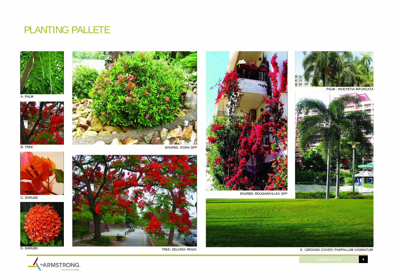
L A N D S C A P E 4
PLANTING PALLETE

L A N D S C A P E 5
HARDSCAPE MATERIAL