adafruit vs1053 mp3/aac/ogg/midi/wav codec breakout tutorial · pdf fileadafruit vs1053...
TRANSCRIPT

Adafruit VS1053 MP3/AAC/Ogg/MIDI/WAV Codec Breakout TutorialCreated by Bill Earl
Last updated on 2016-10-05 03:00:49 PM UTC
247889
10111112121313
14141619191920
2021212122
232324242425252627
Guide Contents
Guide ContentsOverviewAssembly
Prepare the HeadersPosition the BoardAnd Solder!
Getting Started - VS1053 SoftwareSimple Audio Player Wiring
Prepare the breadboardConnect SPI and ResetConnect the rest of the digital signalsConnect the Headphone JackLoad some MP3 files
Simple Audio Player SketchFor the Micro:Audio ConnectionsMIDI Connections
Prepare the breadboardConfigure for MIDI operationConnect the Headphone Jack
Midi Example SketchGPIO
Start with the basic wiringAdd some LEDsRun the player_gpiotest sketch
Ogg RecorderRecording with the VS1053Wiring
Basic SPI connections:Additional Control Signals:Start/Stop Button (Momentary):Electret Microphone Circuit:A note about microphone circuits:Recording Sketch:
© Adafruit Industries https://learn.adafruit.com/adafruit-vs1053-mp3-aac-ogg-midi-wav-play-and-record-codec-tutorial
Page 2 of 34

272727
28282829
2929
32323232
Plug-InsTo Record:To Playback:
Library Referenceclass Adafruit_VS1053_FilePlayer
Public Methods:Public Member Variables:
class Adafruit_VS1053public Methods:
Downloads and LinksLibrary:Files:Schematic & Fabrication Print
© Adafruit Industries https://learn.adafruit.com/adafruit-vs1053-mp3-aac-ogg-midi-wav-play-and-record-codec-tutorial
Page 3 of 34

Overview
Above: v1.0 codec board. Below: v2.0 codec board
© Adafruit Industries https://learn.adafruit.com/adafruit-vs1053-mp3-aac-ogg-midi-wav-play-and-record-codec-tutorial
Page 4 of 34
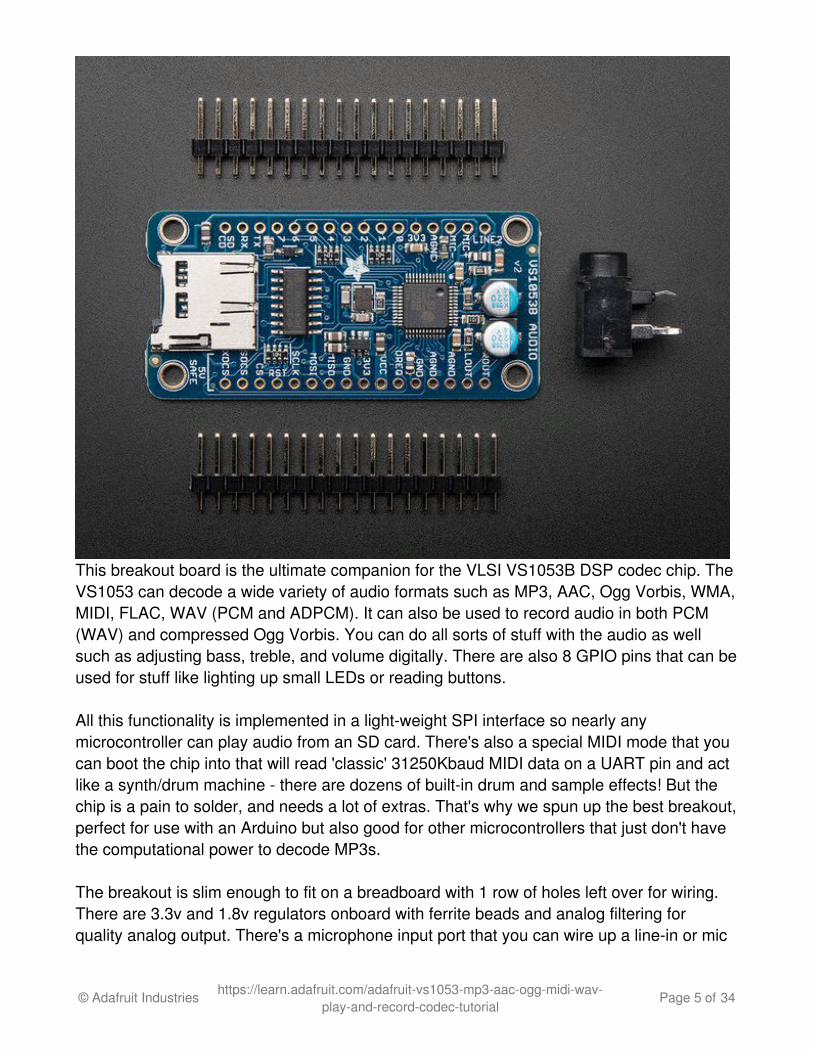
This breakout board is the ultimate companion for the VLSI VS1053B DSP codec chip. TheVS1053 can decode a wide variety of audio formats such as MP3, AAC, Ogg Vorbis, WMA,MIDI, FLAC, WAV (PCM and ADPCM). It can also be used to record audio in both PCM(WAV) and compressed Ogg Vorbis. You can do all sorts of stuff with the audio as wellsuch as adjusting bass, treble, and volume digitally. There are also 8 GPIO pins that can beused for stuff like lighting up small LEDs or reading buttons.
All this functionality is implemented in a light-weight SPI interface so nearly anymicrocontroller can play audio from an SD card. There's also a special MIDI mode that youcan boot the chip into that will read 'classic' 31250Kbaud MIDI data on a UART pin and actlike a synth/drum machine - there are dozens of built-in drum and sample effects! But thechip is a pain to solder, and needs a lot of extras. That's why we spun up the best breakout,perfect for use with an Arduino but also good for other microcontrollers that just don't havethe computational power to decode MP3s.
The breakout is slim enough to fit on a breadboard with 1 row of holes left over for wiring.There are 3.3v and 1.8v regulators onboard with ferrite beads and analog filtering forquality analog output. There's a microphone input port that you can wire up a line-in or mic
© Adafruit Industries https://learn.adafruit.com/adafruit-vs1053-mp3-aac-ogg-midi-wav-play-and-record-codec-tutorial
Page 5 of 34

to and record compressed audio. All 8 GPIO are broken out and they all have built in 100Kpulldowns, simply connect your button from the GPIO pin to 3.3V for an active-highconnection. You'll likely want to play music from a microSD card so we added a holder on-board. And since we know so many of our customers use 5V microcontrollers like theArduino, we made the interface pins all 5V compliant with level shifters so you can use thechip at 3V or 5V power/logic!
The breakout board comes fully assembled and tested. All v1.0 boards come with two100uF electrolytic capacitors for line-level output coupling, v2.0 have the capacitorsintegrated into the PCB. All kits come with some 0.1" male header you can solder to thebreakout so it plugs into a breadboard and a bonus stereo headphone jack that will behandy when you want to plug headphones in!
© Adafruit Industries https://learn.adafruit.com/adafruit-vs1053-mp3-aac-ogg-midi-wav-play-and-record-codec-tutorial
Page 6 of 34

Assembly
The board comes with all surface-mount components assembled and tested. For use on abreadboard, you will want to install the included header strips. This is a simple process andshould only take a few minute
Assembly is the same for both v1 and v2 breakouts, even if the boards look a bitdifferent!
© Adafruit Industries https://learn.adafruit.com/adafruit-vs1053-mp3-aac-ogg-midi-wav-play-and-record-codec-tutorial
Page 7 of 34

Prepare the Headers
Cut the header strips to length ifnecessary and place the long-pins-down in the breadboard.
Position the Board
Place the breakout board overthe header pins.
© Adafruit Industries https://learn.adafruit.com/adafruit-vs1053-mp3-aac-ogg-midi-wav-play-and-record-codec-tutorial
Page 8 of 34
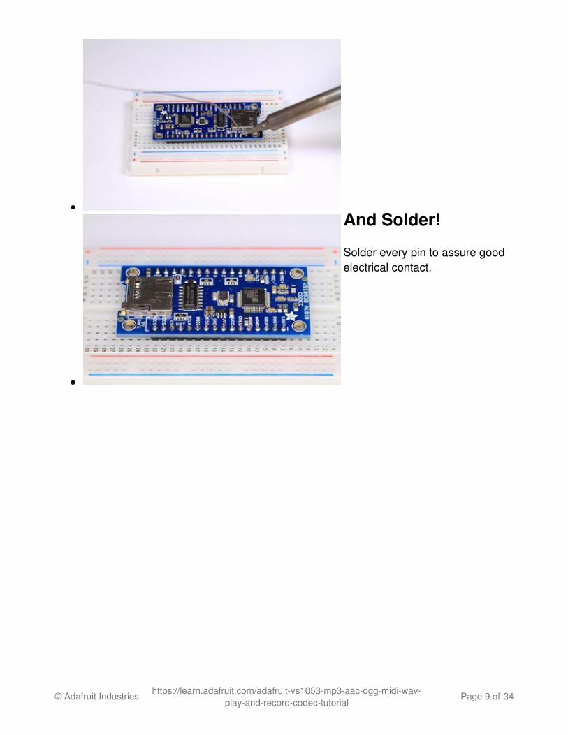
And Solder!
Solder every pin to assure goodelectrical contact.
© Adafruit Industries https://learn.adafruit.com/adafruit-vs1053-mp3-aac-ogg-midi-wav-play-and-record-codec-tutorial
Page 9 of 34

Getting Started - VS1053 SoftwareTo get started with the VS1053 breakout (any version) you will first need to download theAdafruit VS1053 Library:Download Adafruit VS1053 Libraryhttp://adafru.it/cDQ
Copy the folder inside the zip file to the Libraries folder inside your Arduino Sketchbookfolder and re-name it to Adafruit_VS1053 For more details on how to install Arduinolibraries, check out our detailed tutorial using the link below:
All About Arduino Librarieshttp://adafru.it/aYM
© Adafruit Industries https://learn.adafruit.com/adafruit-vs1053-mp3-aac-ogg-midi-wav-play-and-record-codec-tutorial
Page 10 of 34

Simple Audio Player Wiring
The VS1053 can be configured as a simple audio player under control of the Arduino. TheArduino reads data from the on-board SD card, then plays it back through the CODEC viathe SPI interface.
These steps are identical for both v1 and v2 codec breakouts, even if the boards looka little bit different
Prepare thebreadboard
Place the VS1053 breakout onthe breadboard. Center it so that
© Adafruit Industries https://learn.adafruit.com/adafruit-vs1053-mp3-aac-ogg-midi-wav-play-and-record-codec-tutorial
Page 11 of 34

there is one row of holes on eachside.
Add the breakout friendlyheadphone jack and wire powerand ground jumpers as shown.
VCC -> 5vGND -> GND
Connect SPI andReset
Add jumpers for:
CLK -> Arduino #13(Mega 52)MISO -> Arduino #12(Mega 50)MOSI -> Arduino #11(Mega 51)CS -> Arduino #10RST -> Arduino #9
Connect the rest ofthe digital signals
Add more jumpers for:
XDCS-> Arduino #8SDCS -> Arduino #4DREQ -> Arduino #3
© Adafruit Industries https://learn.adafruit.com/adafruit-vs1053-mp3-aac-ogg-midi-wav-play-and-record-codec-tutorial
Page 12 of 34

Connect theHeadphone Jack
This step will be a little bitdifferent depending on whichversion you have. If yourbreakout is v2 and has the roundsilver capacitors, add jumpersfor:
AGND -> Center 'ground'PinLOUT -> Left PinROUT -> Right Pin
(these are in the corner in a row)If your breakout is v1, the pinswill be labeled
GBUF -> Center 'ground'PinLOUT -> Left PinROUT -> Right Pin
For v1, do not use this wiring forpowered speakers or a line-inconnection to a computer/stereo.Only for headphones! For v2,you can use this wiring for anytype of connection without worry.
Load some MP3 files
Copy 2 MP3 files to a micro SD card and name them track001.mp3 and track002.mp3(this is just for the test, you can re-name them later). Then install the card in the slot on theVS1053 breakout.
© Adafruit Industries https://learn.adafruit.com/adafruit-vs1053-mp3-aac-ogg-midi-wav-play-and-record-codec-tutorial
Page 13 of 34
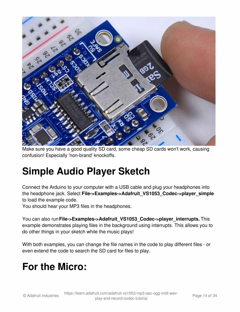
Make sure you have a good quality SD card, some cheap SD cards won't work, causingconfusion! Especially 'non-brand' knockoffs.
Simple Audio Player SketchConnect the Arduino to your computer with a USB cable and plug your headphones intothe headphone jack. Select File->Examples->Adafruit_VS1053_Codec->player_simpleto load the example code.You should hear your MP3 files in the headphones.
You can also run File->Examples->Adafruit_VS1053_Codec->player_interrupts. Thisexample demonstrates playing files in the background using interrupts. This allows you todo other things in your sketch while the music plays!
With both examples, you can change the file names in the code to play different files - oreven extend the code to search the SD card for files to play.
For the Micro:
© Adafruit Industries https://learn.adafruit.com/adafruit-vs1053-mp3-aac-ogg-midi-wav-play-and-record-codec-tutorial
Page 14 of 34

Frank Cohen has submitted a wiring diagram for the FilePlayer example on a Micro. Seehis code posted here as well: http://votsh.files.wordpress.com/2014/02/vs1053-arduino-micro-connections.pdf (http://adafru.it/oHe)
Note: For paying sounds in the background using interrupts, connect DREQ to pin 3 andchange the code to match.
© Adafruit Industries https://learn.adafruit.com/adafruit-vs1053-mp3-aac-ogg-midi-wav-play-and-record-codec-tutorial
Page 15 of 34
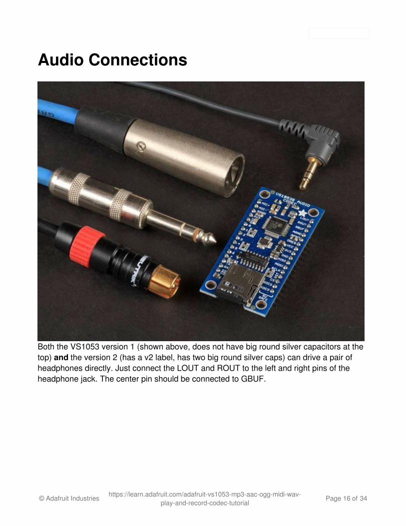
Audio Connections
Both the VS1053 version 1 (shown above, does not have big round silver capacitors at thetop) and the version 2 (has a v2 label, has two big round silver caps) can drive a pair ofheadphones directly. Just connect the LOUT and ROUT to the left and right pins of theheadphone jack. The center pin should be connected to GBUF.
© Adafruit Industries https://learn.adafruit.com/adafruit-vs1053-mp3-aac-ogg-midi-wav-play-and-record-codec-tutorial
Page 16 of 34

Both v1 and v2 can also directly drive audio devices with differential inputs such as our 3.7Watt Stereo Class D Amplifier. Connect LOUT and ROUT to the L+ and R+ pins of theamplifier. Connect L- and R- to the AGND pins.
If you have a v1 breakout, you can connect to powered speakers/stereo BUT YOU
© Adafruit Industries https://learn.adafruit.com/adafruit-vs1053-mp3-aac-ogg-midi-wav-play-and-record-codec-tutorial
Page 17 of 34

MUST USE THE INCLUDED CAPACITORS!
For audio devices requiring a 'line level' input, use the included capacitors. These arepolarized electrolytic capacitors, so it matters which way you connect them. Connect thepositive (longer) leads to the LOUT and ROUT pins, and the negative leads to the L & Rpins of the headphone jack or L and R inputs of the audio device. The common (center) pinof the audio jack should be connected to the AGND pin.
If you have a v2 breakout, these capacitors can be skipped, they are included onto thebreakout board itself.
© Adafruit Industries https://learn.adafruit.com/adafruit-vs1053-mp3-aac-ogg-midi-wav-play-and-record-codec-tutorial
Page 18 of 34
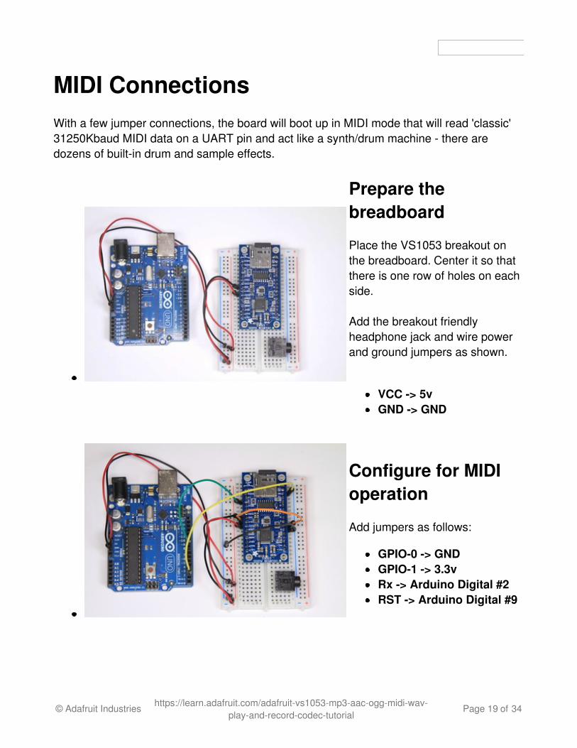
MIDI ConnectionsWith a few jumper connections, the board will boot up in MIDI mode that will read 'classic'31250Kbaud MIDI data on a UART pin and act like a synth/drum machine - there aredozens of built-in drum and sample effects.
Prepare thebreadboard
Place the VS1053 breakout onthe breadboard. Center it so thatthere is one row of holes on eachside.
Add the breakout friendlyheadphone jack and wire powerand ground jumpers as shown.
VCC -> 5vGND -> GND
Configure for MIDIoperation
Add jumpers as follows:
GPIO-0 -> GNDGPIO-1 -> 3.3vRx -> Arduino Digital #2RST -> Arduino Digital #9
© Adafruit Industries https://learn.adafruit.com/adafruit-vs1053-mp3-aac-ogg-midi-wav-play-and-record-codec-tutorial
Page 19 of 34

Connect theHeadphone Jack
Same as the earlier tests, addjumpers for:
AGND (v2) or GBUF (v1) -> Center PinLOUT -> Left PinROUT -> Right Pin
Midi Example SketchConnect the Arduino to your computer with a USB cable and plug your headphones intothe headphone jack. Select File->Examples->Adafruit_VS1053_Codec->player_miditestto load the example code for MIDI operation.. You should hear a repeating series ofascending tones from the MIDI player.
© Adafruit Industries https://learn.adafruit.com/adafruit-vs1053-mp3-aac-ogg-midi-wav-play-and-record-codec-tutorial
Page 20 of 34
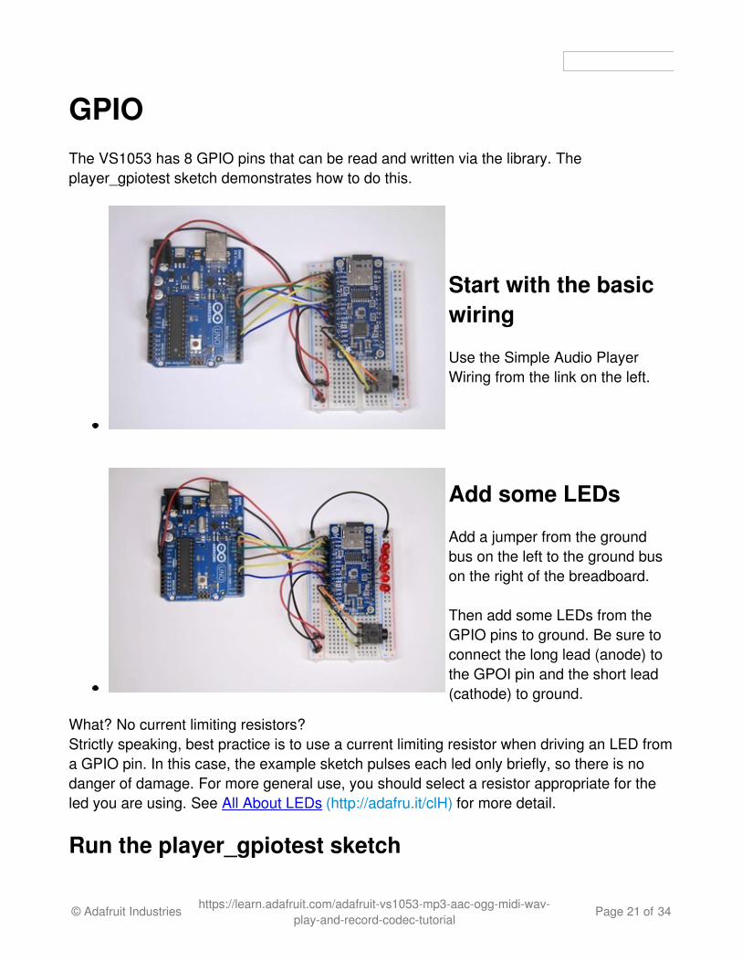
GPIOThe VS1053 has 8 GPIO pins that can be read and written via the library. Theplayer_gpiotest sketch demonstrates how to do this.
Start with the basicwiring
Use the Simple Audio PlayerWiring from the link on the left.
Add some LEDs
Add a jumper from the groundbus on the left to the ground buson the right of the breadboard.
Then add some LEDs from theGPIO pins to ground. Be sure toconnect the long lead (anode) tothe GPOI pin and the short lead(cathode) to ground.
What? No current limiting resistors?Strictly speaking, best practice is to use a current limiting resistor when driving an LED froma GPIO pin. In this case, the example sketch pulses each led only briefly, so there is nodanger of damage. For more general use, you should select a resistor appropriate for theled you are using. See All About LEDs (http://adafru.it/clH) for more detail.
Run the player_gpiotest sketch
© Adafruit Industries https://learn.adafruit.com/adafruit-vs1053-mp3-aac-ogg-midi-wav-play-and-record-codec-tutorial
Page 21 of 34

Connect the Arduino to your computer with a USB cable. Select File->Examples->Adafruit_VS1053->player_gpiotest to load the example code.
If you have headphones, you will hear a beep at the start to indicate that the sketch isrunning. Then you should see the LEDs flashed in sequence.
If you open the Serial Monitor, you can see the values that are written to and read fromeach GPIO pin.
Note that the GPIO pins are NOT 5v safe. Do not connect them to voltages greater than3.3v.
© Adafruit Industries https://learn.adafruit.com/adafruit-vs1053-mp3-aac-ogg-midi-wav-play-and-record-codec-tutorial
Page 22 of 34
Ogg Recorder
(Nipper photo by Bevery & Pack - Creative Commons Share Alike)
Recording with the VS1053The record_ogg example sketch turns your VS1053 breakout into a recording device thatgenerates OGG encoded files on the SD card in real-time.
© Adafruit Industries https://learn.adafruit.com/adafruit-vs1053-mp3-aac-ogg-midi-wav-play-and-record-codec-tutorial
Page 23 of 34

WiringWiring for the record_ogg sketch is as follows:
Power and Ground:
VCC -> 5vGND -> GND
Basic SPI connections:
SCLK -> Arduino #13MOSI -> Arduino #11MISO -> Arduino #12CS -> Arduino #10
Additional Control Signals:
SDCS -> Arduino A0
© Adafruit Industries https://learn.adafruit.com/adafruit-vs1053-mp3-aac-ogg-midi-wav-play-and-record-codec-tutorial
Page 24 of 34

XDCS -> Arduino #8RST -> Arduino #9DREQ -> Arduino A1
Start/Stop Button (Momentary):
from Arduino #7 to GND
Electret Microphone Circuit:
The Microphone circuit is derived from the reference design shown in Figure 3 on Page 13of the VS1053B Datasheet (http://adafru.it/clI). Note that the ground connections shown areto analog ground (AGND).
© Adafruit Industries https://learn.adafruit.com/adafruit-vs1053-mp3-aac-ogg-midi-wav-play-and-record-codec-tutorial
Page 25 of 34

A note about microphone circuits:
© Adafruit Industries https://learn.adafruit.com/adafruit-vs1053-mp3-aac-ogg-midi-wav-play-and-record-codec-tutorial
Page 26 of 34

Microphones, by their nature, are very sensitive devices. They are prone to picking up allsorts of noises (both electrical and acoustic) in addition to what you are trying to record. Amicrophone circuit built on a breadboard is not likely to sound good at all. For good sound,you will want to review the spec sheet recommendations and build this on a good qualitycircuit board.
Recording Sketch:
Connect the Arduino to your computer with a USB cable and plug your headphones intothe headphone jack. Select File->Examples->Adafruit_VS1053_Codec->record_ogg toload the example code.
Plug-Ins
The record_ogg example sketch demonstrates a powerful feature of the VS1053 breakout:Plug-ins. OGG recording capability is not supported natively in the chip itself, but through aplug-in code module. A binary file containing the code image of the plug-in is loaded fromthe SD card at startup. Once loaded, the VS1053 becomes an OGG recording device.
To Record:
Press the start/stop button to start the recording. Press once again to stop. Each recordingwill be stored in a separate .OGG file on the SD card.
To Playback:
Use any OGG capable audio player on your computer - or playback through the VS1053using the Simple Audio Player configuration (see link at left).
© Adafruit Industries https://learn.adafruit.com/adafruit-vs1053-mp3-aac-ogg-midi-wav-play-and-record-codec-tutorial
Page 27 of 34

Library Reference
class Adafruit_VS1053_FilePlayerThe Adafruit_VS1053_FilePlayer class is derived from the Adafruit_VS1053 class andprovides high level functions for playing files stored on the VS1053 breakout SC Cardreader.
Public Methods:
Adafruit_VS1053_FilePlayer (uint8_t mosi, uint8_t miso, uint8_t clk, uint8_t rst,uint8_t cs, uint8_t dcs, uint8_t dreq, uint8_t cardCS) - Software SPI constructor.Uses Software SPI, so you must specify all SPI pins.
Adafruit_VS1053_FilePlayer (uint8_t rst, uint8_t cs, uint8_t dcs, uint8_t dreq,uint8_t cardCS) - Hardware SPI constructor. Uses Hardware SPI and assumes thedefault SPI pins.
boolean begin(void) - Initialize communication and reset the chip.
boolean useInterrupt(uint8_t type) - Specifies the interrupt to use for interrupt-driven playback. Valid arguments are:
VS1053_FILEPLAYER_TIMER0_INT VS1053_FILEPLAYER_PIN_INT
boolean startPlayingFile(char *trackname) - Begin playing the specified file fromthe SD card using interrupt-driven playback. This allows your program to performother tasks as the file is playing.
boolean playFullFile(char *trackname) - Play the complete file. This function will notreturn until the playback is complete.
© Adafruit Industries https://learn.adafruit.com/adafruit-vs1053-mp3-aac-ogg-midi-wav-play-and-record-codec-tutorial
Page 28 of 34

Public Member Variables:
File currentTrack - File currently being played
boolean playingMusic - True if playback in progress
class Adafruit_VS1053The Adafruit_VS1053 class implements an interface to the basic VS1053 functionality. Formore detail on the operation of the VS1053 chip, please refer to the documentation on theDownloads page (see the link to the left).
public Methods:
Adafruit_VS1053(uint8_t mosi, uint8_t miso, uint8_t clk, uint8_t rst, uint8_tcs, uint8_t dcs, uint8_t dreq) - Software SPI constructor - must specify allpins.
Adafruit_VS1053(uint8_t rst, uint8_t cs, uint8_t dcs, uint8_t dreq) -Hardware SPI constructor - assumes hardware SPI pins.
uint8_t begin(void) - Initialize SPI communication and (hard) reset the chip.
void reset(void) - Performs a hard reset of the chip.
void softReset(void) - Attempts a soft reset of the chip.
uint16_t sciRead(uint8_t addr) - Reads from the specified register on the chip.
void sciWrite(uint8_t addr, uint16_t data) - Writes to the specified register onthe chip.
void sineTest(uint8_t n, uint16_t ms) - Generate a sine-wave test signal.
void spiwrite(uint8_t d) - Low-level SPI write operation.
uint8_t spiread(void) - Low-level SPI read operation.
uint16_t decodeTime(void) - Reads the DECODETIME register from the chip.
© Adafruit Industries https://learn.adafruit.com/adafruit-vs1053-mp3-aac-ogg-midi-wav-play-and-record-codec-tutorial
Page 29 of 34

void setVolume(uint8_t left, uint8_t right) - Set the output volume for thechip.
void dumpRegs(void) - Prints the contents of the MODE, STATUS, CLOCKFand VOLUME registers.
void playData(uint8_t *buffer, uint8_t buffsiz) - Decode and play the contentsof the supplied buffer.
boolean readyForData(void) - Test if ready for more data.
void applyPatch(const uint16_t *patch, uint16_t patchsize) - Apply a codepatch (See datasheet for details).
uint16_t loadPlugin(char *fn) - Load the specified plug-in.
void GPIO_digitalWrite(uint8_t i, uint8_t val) - Write to a GPIO pin.
void GPIO_digitalWrite(uint8_t i) - Write to all 8 GPIO pins at once.
uint16_t GPIO_digitalRead(void) - Read all 8 GPIO pins at once.
boolean GPIO_digitalRead(uint8_t i) - Read a single GPIO pin.
void GPIO_pinMode(uint8_t i, uint8_t dir) - Set the Pin Mode(INPUT/OUTPUT) for a GPIO pin.
boolean prepareRecordOgg(char *plugin) - Initialize chip for OGG recording.
void startRecordOgg(boolean mic) - Start recording (mic = true formicrophone input).
void stopRecordOgg(void) - Stop the recording.
uint16_t recordedWordsWaiting(void) - Returns the number of wordsrecorded.
uint16_t recordedReadWord(void) - Reads the next word from the buffer ofrecorded words.
uint16_t recordedReadWord(void) - Reads the next word from the buffer of
© Adafruit Industries https://learn.adafruit.com/adafruit-vs1053-mp3-aac-ogg-midi-wav-play-and-record-codec-tutorial
Page 30 of 34
recorded words.
© Adafruit Industries https://learn.adafruit.com/adafruit-vs1053-mp3-aac-ogg-midi-wav-play-and-record-codec-tutorial
Page 31 of 34

Downloads and Links
Library:Adafruit VS1053 Library (http://adafru.it/clE)
Files:VS1053B (Codec chip) datasheet (http://adafru.it/clI)Details about the Ogg vorbis encoder/recorder (http://adafru.it/clJ)App note on connecting to analog outputs! (http://adafru.it/clK)Fritzing object in Adafruit Fritzing Library (http://adafru.it/aP3)EagleCAD PCB files on GitHub (http://adafru.it/qIa)
Schematic & Fabrication Print
© Adafruit Industries https://learn.adafruit.com/adafruit-vs1053-mp3-aac-ogg-midi-wav-play-and-record-codec-tutorial
Page 32 of 34

© Adafruit Industries https://learn.adafruit.com/adafruit-vs1053-mp3-aac-ogg-midi-wav-play-and-record-codec-tutorial
Page 33 of 34

© Adafruit Industries Last Updated: 2016-10-05 03:00:48 PM UTC Page 34 of 34