adaptive autoreclosure to increase system stability and...
TRANSCRIPT
© Siemens AG 2017 All rights reserved. siemens.com/energy-management
Adaptive Autoreclosure to Increase System Stability and Reduce Stress to Circuit Breakers70th Annual Conference for Protective Relay Engineers

2017-04-05Page 2 Jörg Blumschein / Energy Management
Why using autoreclosure
• 80 to 85 % of faults at transmission and distribution lines are temporary faults
• Most important causes of temporary faults
• Lightning is the most usual case for temporary faults
• Bird streamers or vegetation reaching too close to the conductors
• Swinging conductors contacting each other cause temporary phase to phasefaults
• These faults disappear a certain time after de-energization of the faulted sections
• Automatic reclosure is used to recover the original status of the networkvery fast and without any human interaction
2017-04-05Page 3 Jörg Blumschein / Energy Management
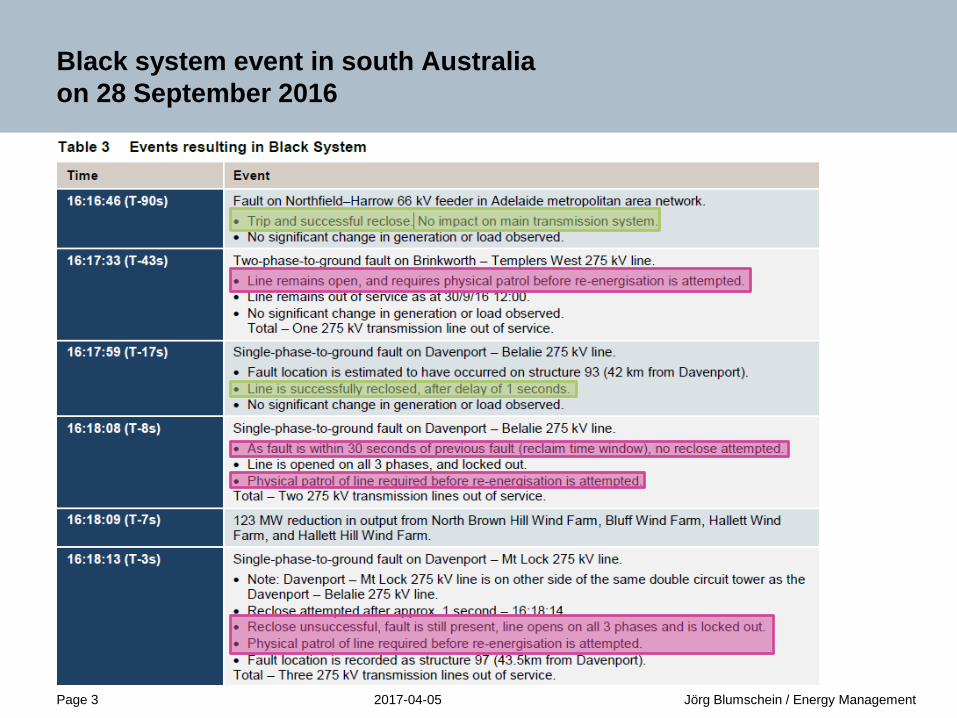
Black system event in south Australiaon 28 September 2016
2017-04-05Page 4 Jörg Blumschein / Energy Management
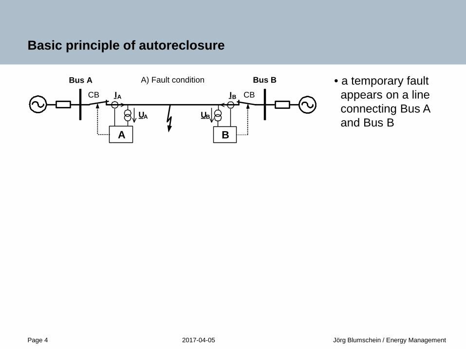
Basic principle of autoreclosure
• a temporary faultappears on a lineconnecting Bus Aand Bus B
• relays A and B sendtrip command andstart the dead timeof the autoreclosure
• after the dead time isexpired, the automaticreclosure sends aclose command to thecircuit breaker
A
Bus A
UA
IACB
Bus B
B
UB
IB CB
A
Bus A
UA
IACB
Bus B
B
UB
IB CB
A
Bus A
UA
IACB
Bus B
B
UB
IB CB
B) line open
A) Fault condition
C) successful reclosure

2017-04-05Page 5 Jörg Blumschein / Energy Management
Autoreclosure schemes for different types of fault
Single phase to ground fault
Phase to phase fault
Phase to phase to
ground fault
Three phase fault
Single pole autoreclosure Three pole autoreclosure
Autoreclosure with adaptive dead time
Secondary arc detection
Fault extinction detection
2017-04-05Page 6 Jörg Blumschein / Energy Management
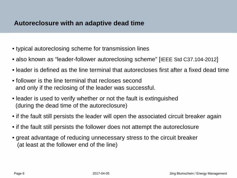
Autoreclosure with an adaptive dead time
• typical autoreclosing scheme for transmission lines
• also known as “leader-follower autoreclosing scheme” [IEEE Std C37.104-2012]
• leader is defined as the line terminal that autorecloses first after a fixed dead time
• follower is the line terminal that recloses secondand only if the reclosing of the leader was successful.
• leader is used to verify whether or not the fault is extinguished(during the dead time of the autoreclosure)
• if the fault still persists the leader will open the associated circuit breaker again
• if the fault still persists the follower does not attempt the autoreclosure
• great advantage of reducing unnecessary stress to the circuit breaker(at least at the follower end of the line)

2017-04-05Page 7 Jörg Blumschein / Energy Management
Unsuccessful autoreclosure with adaptive dead time
• a fault appears on a lineprotected by the relays called L(leader) and F (follower)
• both relays detect the fault andopen the line by means of theassociated circuit breakers
• after the fixed dead time isexpired only the leader reclosesthe breaker to verify whether ornot the fault still persists
• if the fault still persists, theleader opens the circuit breakerto start another autoreclosecycle or send a final trip
CB CB
CB CB
CB CB
B) Line open
A) Fault condition
C) Leader reclosure unsuccessful
CB CBD) Final trip
L
FL
L F
L F
F
2017-04-05Page 8 Jörg Blumschein / Energy Management
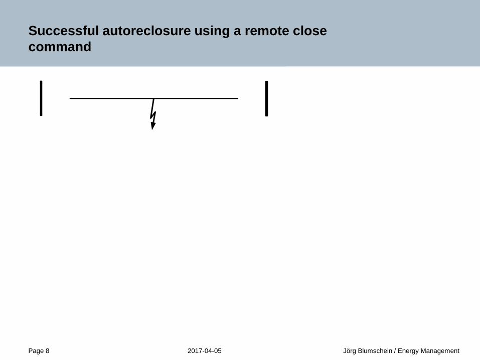
Successful autoreclosure using a remote close command
• the fault does not persist afterreclosing of the leader side
• the leader can send a “remoteclose command” to close thecircuit breaker associated to thefollower at the remote end of theline
2017-04-05Page 9 Jörg Blumschein / Energy Management
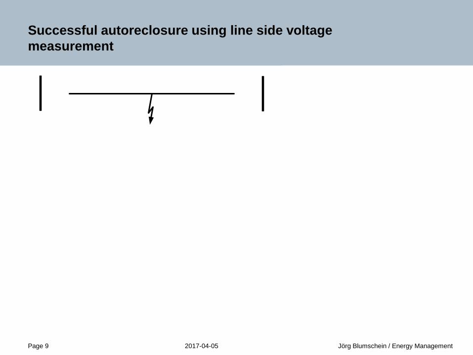
Successful autoreclosure using line side voltage measurement
• after the fixed dead time isexpired the leader closes theassociated circuit breaker
• If the fault does not persistanymore the follower will detecta healthy voltage which indicatesthat the line was successfully re-energized from the remote end
• Consequentially the autoreclosefunction in the follower can closethe circuit breaker
2017-04-05Page 10 Jörg Blumschein / Energy Management
Secondary arc detection
A successful autoreclosure requires a dead time which exceeds the de-ionizing time, the time needed for the fault to extinguish.The de-ionizing time depends on several factors including:
• arcing time (fault duration)
• fault current
• weather conditions like wind, air humidity and air pressure
• circuit voltage
• capacitive coupling to adjacent conductors
In general the circuit voltage is the predominating factor influencing the de-ionizing time. For single pole autoreclosure there is another effect which has a significant influence to the success of the autoreclosure. The primary arc current is interrupted by disconnecting the faulted phase from the sources by opening the circuit breakers at both ends of the line.After this a secondary arc can prevent the fault clearance.
2017-04-05Page 11 Jörg Blumschein / Energy Management
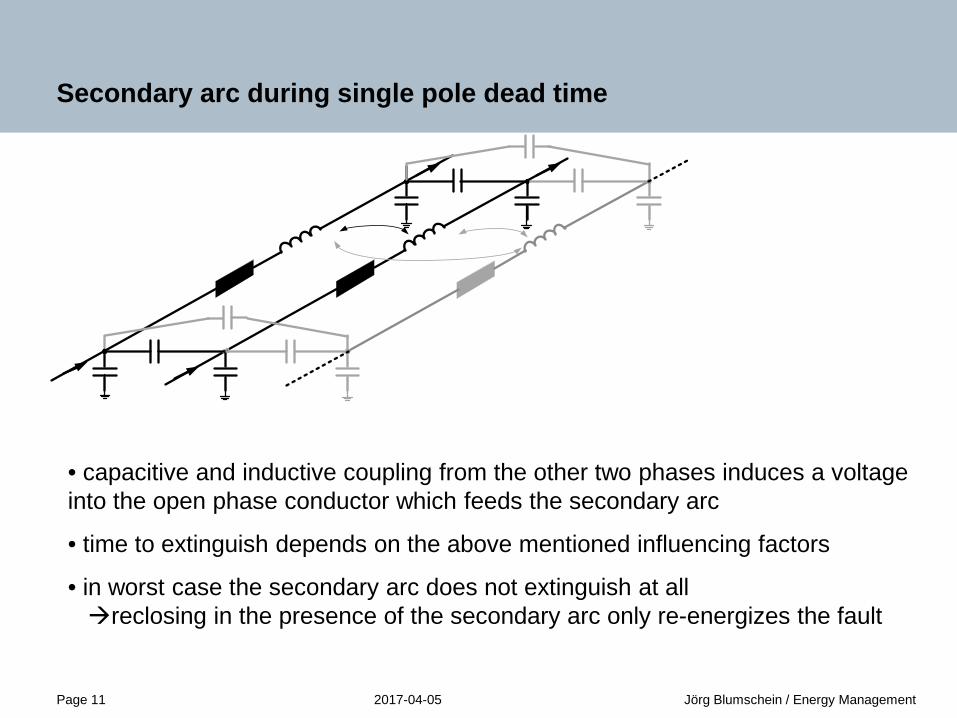
Secondary arc during single pole dead time
• capacitive and inductive coupling from the other two phases induces a voltage into the open phase conductor which feeds the secondary arc
• time to extinguish depends on the above mentioned influencing factors
• in worst case the secondary arc does not extinguish at allreclosing in the presence of the secondary arc only re-energizes the fault
2017-04-05Page 12 Jörg Blumschein / Energy Management
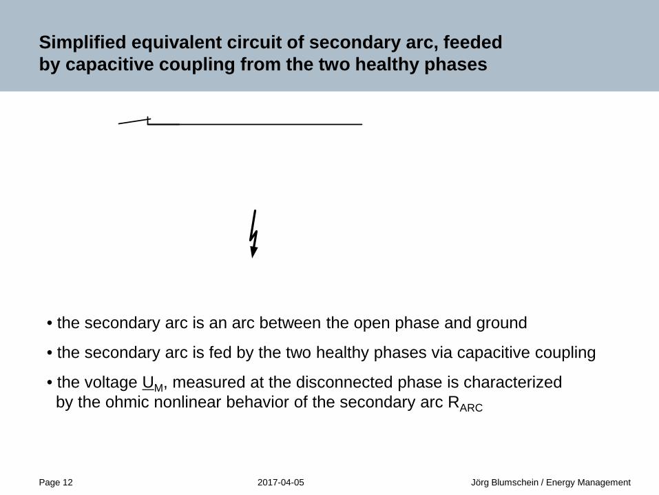
Simplified equivalent circuit of secondary arc, feededby capacitive coupling from the two healthy phases
• the secondary arc is an arc between the open phase and ground
• the secondary arc is fed by the two healthy phases via capacitive coupling
• the voltage UM, measured at the disconnected phase is characterizedby the ohmic nonlinear behavior of the secondary arc RARC

2017-04-05Page 13 Jörg Blumschein / Energy Management
Simplified equivalent circuit after secondary arc is extinguished
• equivalent circuit is changing to a different model
• the voltage UM, measured at the disconnected phase after extinguishing of thesecondary arc is characterized by the linear capacitive behavior of thephase to ground capacitance CCG of the open conductor
2017-04-05Page 14 Jörg Blumschein / Energy Management
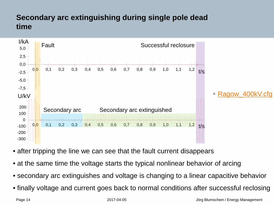
Secondary arc extinguishing during single pole dead time
• after tripping the line we can see that the fault current disappears
• at the same time the voltage starts the typical nonlinear behavior of arcing
• secondary arc extinguishes and voltage is changing to a linear capacitive behavior
• finally voltage and current goes back to normal conditions after successful reclosing
t/s0,0 0,1 0,2 0,3 0,4 0,5 0,6 0,7 0,8 0,9 1,0 1,1 1,2
I/kA
-7,5
-5,0
-2,5
0,0
2,5
5,0
t/s0,0 0,1 0,2 0,3 0,4 0,5 0,6 0,7 0,8 0,9 1,0 1,1 1,2
U/kV
-300-200-100
0100200
Fault
Secondary arc Secondary arc extinguished
Successful reclosure
Ragow_400kV.cfg

2017-04-05Page 15 Jörg Blumschein / Energy Management
Secondary arc not extinguishing during single pole dead time
• after reclosurethe fault still persistswhich leads to a finaltrip of the protection
I/kA
-5,0
-2,5
0,0
2,5
5,0
U/kV
-300
-200
-100
0
100
200
t/s0,00 0,25 0,50 0,75 1,00 1,25 1,50 1,75CloseTRIP CTRIP BTRIP A
Faultunsuccessful
reclosure
Secondary arc
t/s0,00 0,25 0,50 0,75 1,00 1,25 1,50 1,75
t/s0,00 0,25 0,50 0,75 1,00 1,25 1,50 1,75
2017-04-05Page 16 Jörg Blumschein / Energy Management
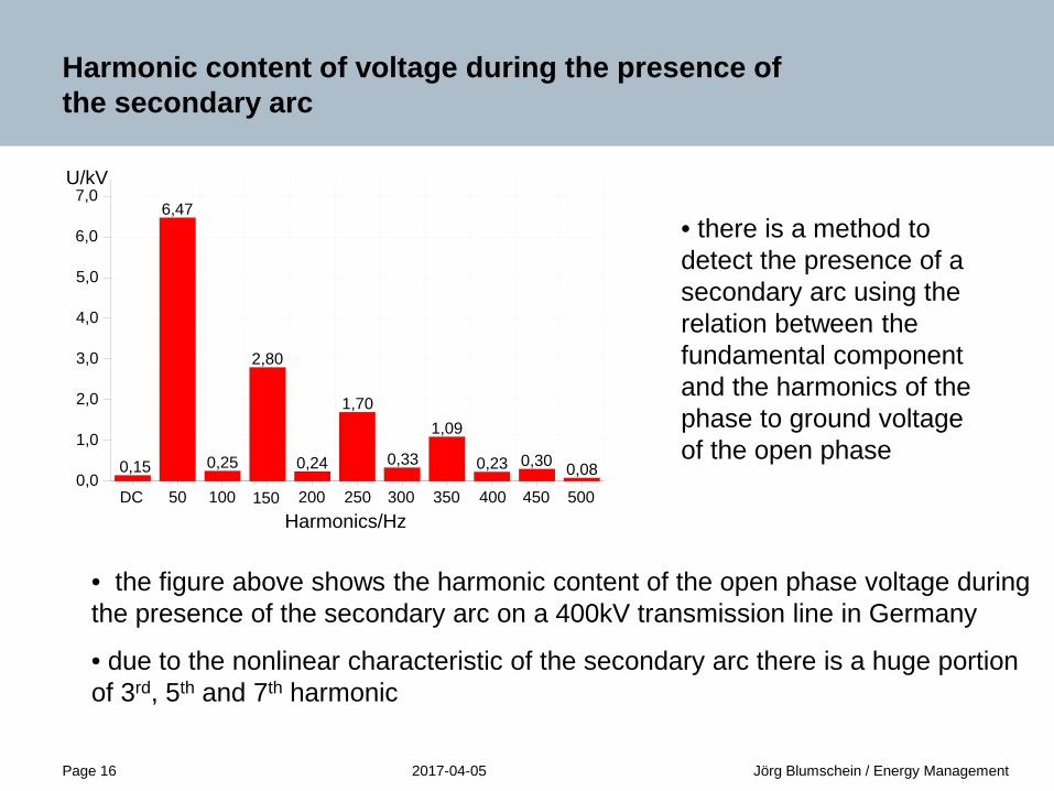
Harmonic content of voltage during the presence of the secondary arc
• the figure above shows the harmonic content of the open phase voltage during the presence of the secondary arc on a 400kV transmission line in Germany
• due to the nonlinear characteristic of the secondary arc there is a huge portion of 3rd, 5th and 7th harmonic
0,15
6,47
0,25
2,80
0,24
1,70
0,33
1,09
0,23 0,30 0,08
Harmonics/HzDC 50 100 150 200 250 300 350 400 450 500
U/kV
0,0
1,0
2,0
3,0
4,0
5,0
6,0
7,0
• there is a method to detect the presence of a secondary arc using the relation between the fundamental component and the harmonics of the phase to ground voltage of the open phase
2017-04-05Page 17 Jörg Blumschein / Energy Management
Harmonic content of voltage after secondary arc is extinguished
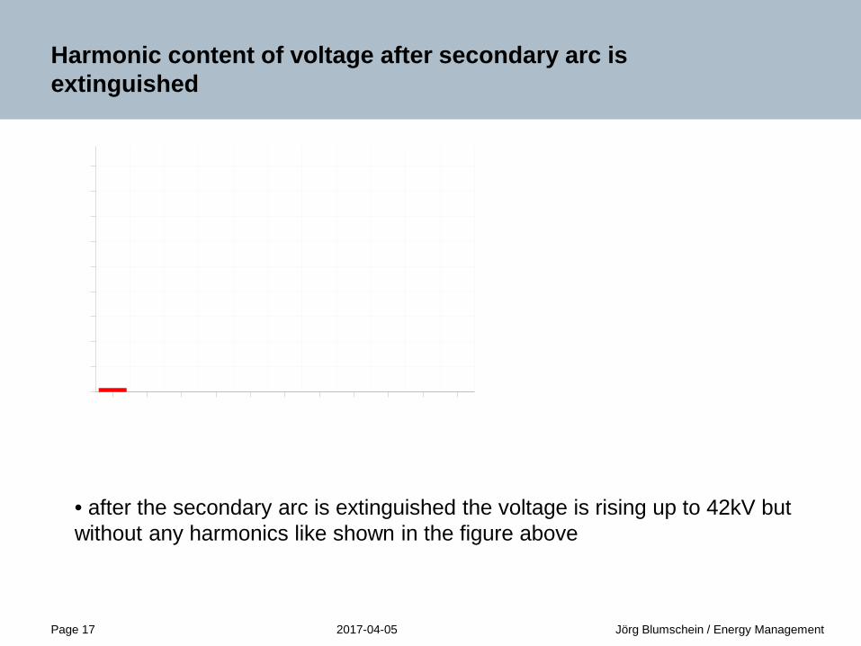
• after the secondary arc is extinguished the voltage is rising up to 42kV but without any harmonics like shown in the figure above
2017-04-05Page 18 Jörg Blumschein / Energy Management
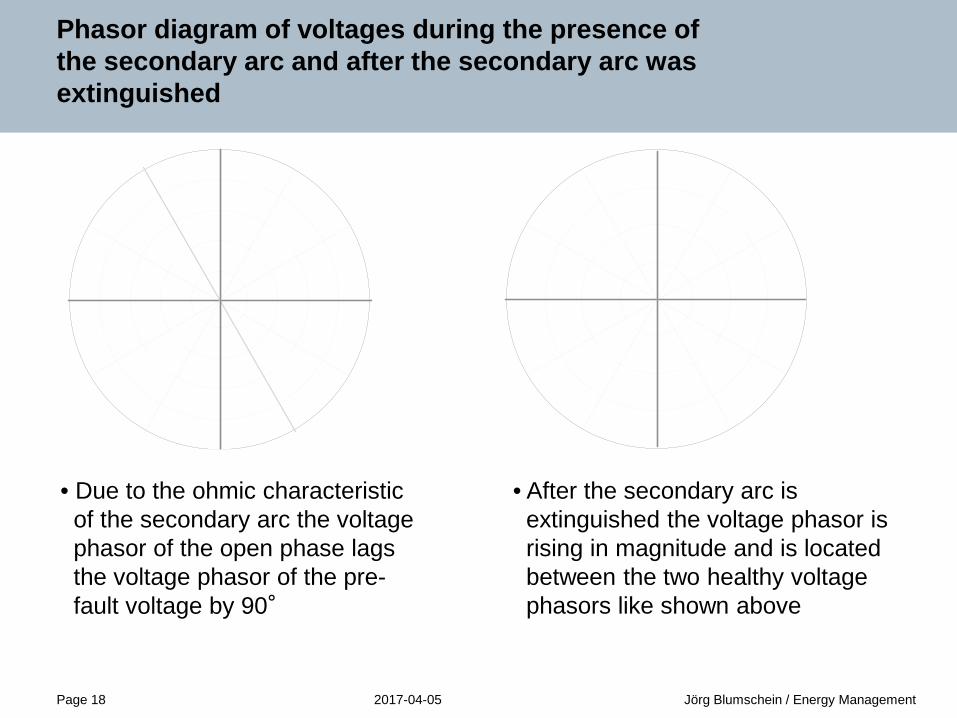
Phasor diagram of voltages during the presence of the secondary arc and after the secondary arc was extinguished
• After the secondary arc isextinguished the voltage phasor isrising in magnitude and is locatedbetween the two healthy voltagephasors like shown above
• Due to the ohmic characteristicof the secondary arc the voltagephasor of the open phase lagsthe voltage phasor of the pre-fault voltage by 90°
2017-04-05Page 19 Jörg Blumschein / Energy Management
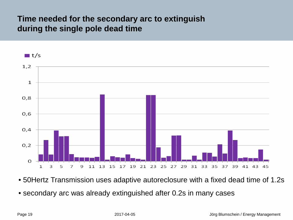
Time needed for the secondary arc to extinguish during the single pole dead time
• 50Hertz Transmission uses adaptive autoreclosure with a fixed dead time of 1.2s
• secondary arc was already extinguished after 0.2s in many cases

2017-04-05Page 20 Jörg Blumschein / Energy Management
Advantages of secondary arc detection
Secondary arc detection as part of the autoreclosure function
• the fixed dead time for the leader could be reduced significantly in most cases
• reclosing onto permanent fault could be prevented for the leader
Secondary arc detection as part of post fault analysis
• if a secondary arc and not a permanent fault was the reason for the unsuccessfulreclosure, a manual closing of the line is permitted without a time consuming linepatrol in advance

2017-04-05Page 21 Jörg Blumschein / Energy Management
Single pole tripping for phase to phase faults without ground
Under extreme weather conditions line swinging can cause an increasing number of phase to phase faults.
These faults are mostly flash-arcs between two wires of a transmission or distribution line.
A

2017-04-05Page 22 Jörg Blumschein / Energy Management
Single pole tripping for phase to phase faults without ground
It is obvious like shown in the figure that a single pole trip will clear a temporary phase to phase fault in most cases.
In 1972 a scheme was protected by patent to clear phase to phase faults without ground by means of a single pole autoreclosure.
A
2017-04-05Page 23 Jörg Blumschein / Energy Management
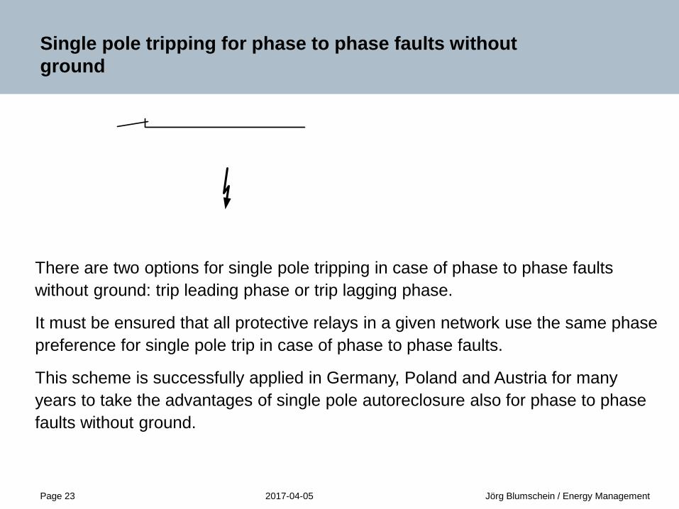
Single pole tripping for phase to phase faults without ground
There are two options for single pole tripping in case of phase to phase faults without ground: trip leading phase or trip lagging phase.
It must be ensured that all protective relays in a given network use the same phase preference for single pole trip in case of phase to phase faults.
This scheme is successfully applied in Germany, Poland and Austria for many years to take the advantages of single pole autoreclosure also for phase to phase faults without ground.
A

2017-04-05Page 24 Jörg Blumschein / Energy Management
Successful single pole autoreclosure of phase C for a fault between phase A and phase C
t/s0,0 0,2 0,4 0,6 0,8 1,0 1,2 1,4 1,6
I A/kA
-10-505
t/s0,0 0,2 0,4 0,6 0,8 1,0 1,2 1,4 1,6
I B/kA
-10-505
t/s0,0 0,2 0,4 0,6 0,8 1,0 1,2 1,4 1,6
I C/kA
-10-505
U A/kV
-200-100
0100
U B/kV
-200-100
0100
U C/kV
-200-100
0100
t/s0,0 0,2 0,4 0,6 0,8 1,0 1,2 1,4 1,6Close
TRIP CTRIP BTRIP A
t/s0,0 0,2 0,4 0,6 0,8 1,0 1,2 1,4 1,6
t/s0,0 0,2 0,4 0,6 0,8 1,0 1,2 1,4 1,6
t/s0,0 0,2 0,4 0,6 0,8 1,0 1,2 1,4 1,6
• After tripping of phase C the fault current in phase A and phase C disappears at the local end.
• Approximately 300ms later also the voltage UC goes down indicating the isolation of the fault.
• Finally a successful reclosurebrought the system back to normal conditions.
• A successful isolation of the arc between the two faulted phases is given if the phase to ground voltage of the tripped phase is measured to be below a certain value for a given time.
2017-04-05Page 25 Jörg Blumschein / Energy Management
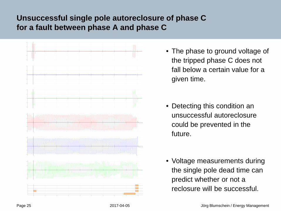
Unsuccessful single pole autoreclosure of phase C for a fault between phase A and phase C
• The phase to ground voltage of the tripped phase C does not fall below a certain value for a given time.
• Detecting this condition an unsuccessful autoreclosurecould be prevented in the future.
• Voltage measurements during the single pole dead time can predict whether or not a reclosure will be successful.

2017-04-05Page 26 Jörg Blumschein / Energy Management
Conclusion
• It was shown that using adaptive autoreclosure the system stability can be increased by adaptively shorten the dead time of the autoreclosure and prevent unnecessary reclosing onto faults.
• Several different methods were explained how to use voltage measurement during the single pole dead time to reduce unnecessary stress to the circuit breaker by reclosing onto faults.

2017-04-05Page 27 Jörg Blumschein / Energy Management
Thank you for your attention!
siemens.com/answers
Questions?