adaptive back-stepping control applied on octocopter under
TRANSCRIPT
Journal of Engineering Science and Military Technologies ISSN: 2357- 0954Volume (1) - Issue (1) - 2017 DOI: 10.21608/ejmtc.2017.401.1004
12 2357-0954 © 2017 The Military Technical College
Key words:
Adaptive back-stepping control, octocopte, stabilization, paintball gun
Corresponding Author: Guangxue Zhang, INSA (National Institute of Applied Sciences) Toulouse, France College, Email:[email protected], Tel.: 627773882
AbstractUnmanned air vehicles such as quadcopters are wildly being used in research and academic projects in the field of aerospace. Whether the mission is to take photos and videos, or simply fly to a given place, the problem of stabilization needs to be primarily considered. To deal with uncertainty and disturbance, traditional PID controller is a basic solution. In order to achieve better quality of robustness, sliding mode control and back-stepping control both bring great improvement to drone stabilization. This paper deals with the problem of stabilization under specific shooting disturbance. The overall system consists of a drone carrying a paintball gun via a gimbal and a servo-motor is used to pull the trigger. As the payload is quite heavy and normal quadcopter cannot afford much weight, an octocopter is considered to be used. One of the possible applications of this project is to replace policemen during a close-in gun conflict.
I. INTRODUCTION Recently UAV is being widely used not only for taking
videos but as a platform for various tasks such as farming observation, goods delivery and photography. Other than carrying a camera, when UAV connects with a device that rapidly launches small projectiles, the recoil destabilizes the vehicle and thus quick stabilization becomes an important issue. This paper presents a propeller control scheme suitable for the UAV with such a launching device.
There were many attempts to solve this problem using various controllers.[1] proposed a controller named Fuzzy+PID which reduces the overshoot compared with the traditional PID controller. The capability of dealing with uncertainty is simulated under random disturbance. Nonetheless, the PID controller has limited performance in dealing with nonlinear dynamic system and thus nonlinear control methods such as feedback linearization, back-stepping and sliding mode control are necessary. Some works of sliding mode control such as[2] and second order sliding mode control[3] showed very good performance of tracking to a given place but did not inject an influential disturbance to test the capability of dealing with the uncertainty. Another work[4] used backstopping design including input saturation to keep the UAV in hover state. However, the response time is long, typically ranging from 10 to 20s.
This paper applies adaptive back-stepping control
scheme[5] to stabilize an octocopter firing a paintball gun. When the trigger is pulled by a servo motor, the paintball gun fires a projectile and thereby delivers significant recoil to the vehicle. The shot disturbance is known to the octocopter because the shooting is conducted by the vehicle itself. This disturbance, therefore, can be corrected by the compensator performing a pre-defined order to eight propellers at the moment the shot is fired. Different from traditional back-stepping control, however, adaptive laws in this work optimize the control result by allowing the controller to modify coefficients in real time according to the present errors between the input and the output.
Simulations are carried out for three cases: without any disturbance; with six shots disturbance; with six shots disturbance and white noise in the background to imitate a real situation. Results show that under disturbance of six consecutive shots the compensator restabilizes the octocopter both in attitude, position and altitude within 2% error and within 3.28 s. Overshoots of position and altitude are always under 2% error. The overshoot of pitch and roll angle are 11.47% and 4.7%, respectively, which have decreased significantly by 53.8% and 42.8% using compensator.
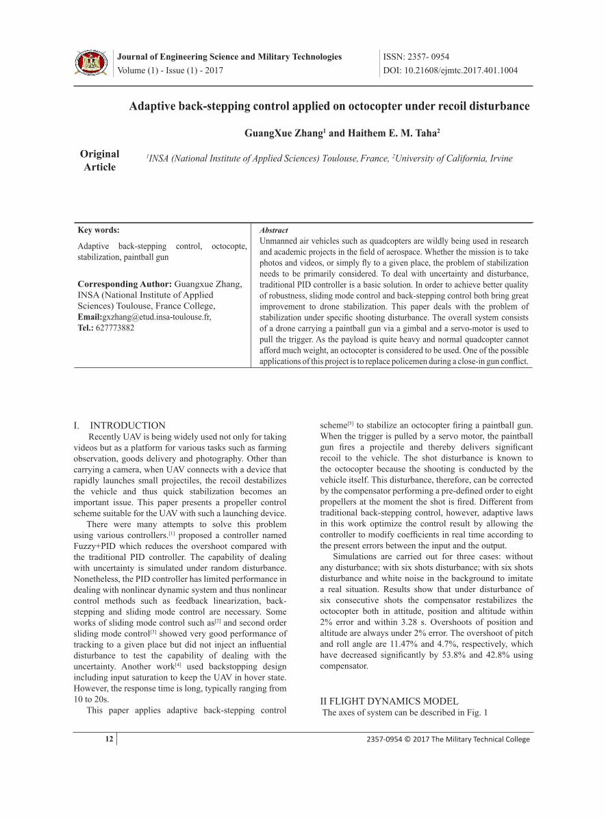
II FLIGHT DYNAMICS MODEL The axes of system can be described in Fig. 1
Original Article
Adaptive back-stepping control applied on octocopter under recoil disturbance
GuangXue Zhang1 and Haithem E. M. Taha2
1INSA (National Institute of Applied Sciences) Toulouse, France, 2University of California, Irvine
Engineering of Science and Military TechnologiesVolume (1) - Issue (1) - 2017
13
Fig. 1: Axes of octocopter.
2.1 Equations of Motion According to reference[5], the equations of motion for
linear and angular movement are written as
Where P is the linear momentum is the angular momentum, ω is the angular velocity and I is moment of inertia matrix. In body reference, considering only the scalar values, Eq. (1) can be written in matrix form as shown in[6],
Where I33 and 033 are 3×3 identity matrix and 3×3 zero matrix, respectively.
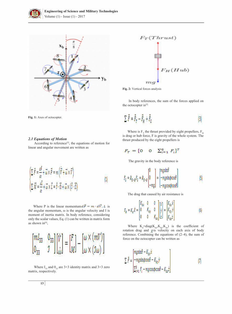
Fig. 2: Vertical forces analysis
In body references, the sum of the forces applied on the octocopter is[5]
Where is FT the thrust provided by eight propellers, FH is drag or hub force, F is gravity of the whole system. The thrust produced by the eight propellers is
The gravity in the body reference is
The drag that caused by air resistance is
Where Kd=diag(Kdx,Kdy,Kdz) is the coefficient of rotation drag and is velocity on each axis of body reference. Combining the equations of (2–4), the sum of force on the octocopter can be written as
GuangXue Zhang and Haithem E. M. Taha
14
In the linear and angular velocity vector in the body reference frame axe denoted by
The right part of Eq. (2) can be rewritten as
The first line of Eq. (2) becomes
Combined with the Eq. (7) we can get the equations of linear movement as
2.3 Moment Analysis As the octocopter is symmetric, the matrix of moment
of inertia is
According to[7], the second line of Eq. (2) can be written as
The moments due to propellers' thrust are
Where is thrust provided by the propeller where b is the thrust coefficient and Ω_i is the angular velocity of the ith propeller. M_Di is the moment of rotation about the z-axis. If the propeller orients with clockwise direction, the moment is in +z direction, otherwise the moment is in -z direction. . Combine equations (11),(12) and the second line of Eq. (2), the Euler's equations can be written as
2.4 Kinematics Equations The translation movement of octocopter in the earth
reference so that the velocity on each axis of earth reference represented by velocity in body reference is
The transfer matrix from body reference to earth reference , so that the translation equations are[8]
According to reference [5]shows that the rotation equations which refer to relationship between the attitude angles and angular velocity in body reference is
2.5 Control Inputs The real input control is the propellers' angular velocity
which controlled by DC motor. The thrust is determined by angular velocity of each propeller which controls the altitude and Euler angle related to the attitude. There are in total four controllers which are thrust controller or altitude controller (U1), roll controller U2, pitch controller U3 and yaw controller U4. As there are eight propellers, the number of variables, which is eight, is higher than the number of four controller equations. In order to keep the attitude in a horizontal level and simplify the calculation, each propeller is assigned to have the same basic value as
Engineering of Science and Military TechnologiesVolume (1) - Issue (1) - 2017
15
Thrust and add or subtract three variables referring to the variation on roll, pitch and yaw angle.
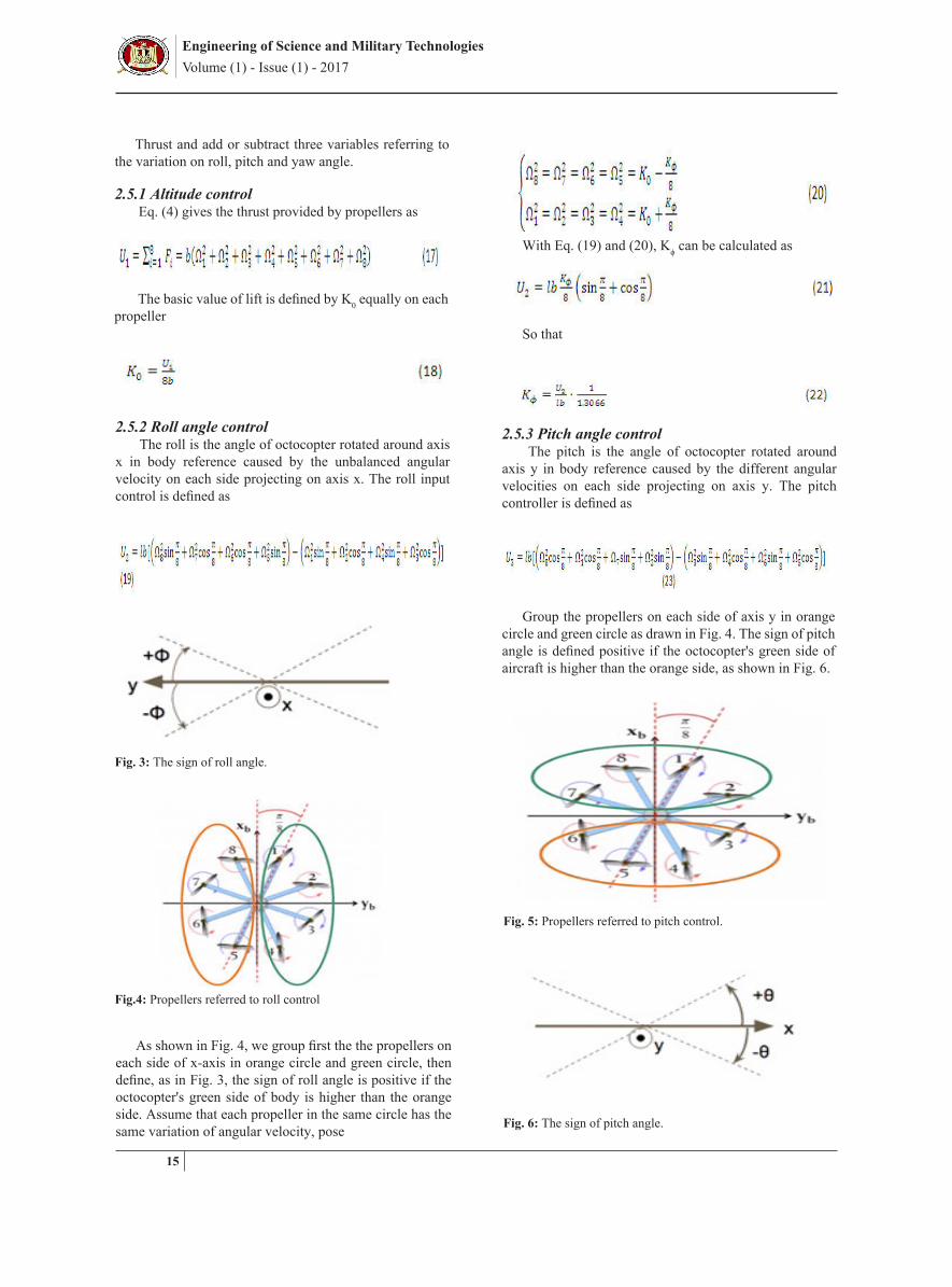
2.5.1 Altitude control Eq. (4) gives the thrust provided by propellers as
The basic value of lift is defined by K0 equally on each propeller
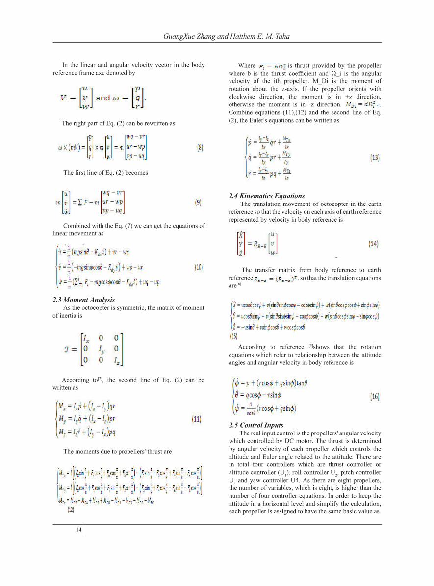
2.5.2 Roll angle control The roll is the angle of octocopter rotated around axis
x in body reference caused by the unbalanced angular velocity on each side projecting on axis x. The roll input control is defined as
Fig. 3: The sign of roll angle.
With Eq. (19) and (20), Kϕ can be calculated as
So that
2.5.3 Pitch angle control The pitch is the angle of octocopter rotated around
axis y in body reference caused by the different angular velocities on each side projecting on axis y. The pitch controller is defined as
Group the propellers on each side of axis y in orange circle and green circle as drawn in Fig. 4. The sign of pitch angle is defined positive if the octocopter's green side of aircraft is higher than the orange side, as shown in Fig. 6.
As shown in Fig. 4, we group first the the propellers on each side of x-axis in orange circle and green circle, then define, as in Fig. 3, the sign of roll angle is positive if the octocopter's green side of body is higher than the orange side. Assume that each propeller in the same circle has the same variation of angular velocity, pose
Fig. 5: Propellers referred to pitch control.
Fig. 6: The sign of pitch angle.
Fig.4: Propellers referred to roll control

GuangXue Zhang and Haithem E. M. Taha
16
Same way to calculate the pitch angle assuming that here is no other posture angles change
With Eq. (23) and (24), variable Kθ is calculated as
2.5.4 Yaw angle control Propeller's rotation direction gives an opposite
moment to the aircraft, so that the yaw control is achieved by grouping all the propellers in clockwise direction minus the rest with opposite direction. The yaw controller is defined as
Group the propellers of clockwise direction in green circle and the opposite direction in orange circle as in Fig. 7. The sign of yaw angle is defined positive if the aircraft turns clockwise as shown in Fig. 8.
Fig. 7: Propellers referred to yaw control.
Fig. 8: The sign of yaw angle.
Assume that there is no change in pitch nor roll angle
With Eq. (26) and (27), Kψ can be written as
2.5.5 Inverse Relation For each propeller, combining Eq. (20), (24) and (27)
together, the input control angular velocity in square of each propeller can be written as
Where
2.6 Power dissipation on motor A DC motor consists an inductor, resistor and the motor
which connects with propellers. The electrical equations is
The UE(t)=KEω(t) is the voltage of motor. The mechanical equation is
From the Eq. (32) we can calculate the derivative of I(t)
Apply Eq. (33) to equation (31), the voltage of each propeller can be expressed by its angular velocity
Engineering of Science and Military TechnologiesVolume (1) - Issue (1) - 2017
17
Therefore, the transient power dissipation of each propeller can be calculated by the multiples of voltage and current.
III. ADAPTIVE BACK-STEPPING CONTROL Adaptive Back-stepping control is widely used in non-
linear system. Back-stepping has very good performance in dealing with robustness. Basically, in the case that the input is not sufficient to regulate the output, this algorithm retreat one step and an intermediate controller named virtual control is created. Adaptive technology allows the system to modify the parameters on-line by adding an estimator so that the system can adjust errors rapidly.
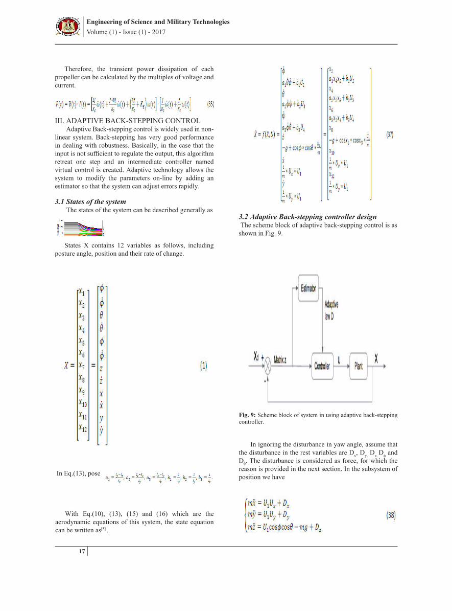
3.1 States of the system The states of the system can be described generally as
States X contains 12 variables as follows, including posture angle, position and their rate of change.
In Eq.(13), pose
With Eq.(10), (13), (15) and (16) which are the aerodynamic equations of this system, the state equation can be written as[5] .
3.2 Adaptive Back-stepping controller design The scheme block of adaptive back-stepping control is as shown in Fig. 9.
Fig. 9: Scheme block of system in using adaptive back-stepping controller.
In ignoring the disturbance in yaw angle, assume that the disturbance in the rest variables are Dx, Dy, Dz, Dϕ and Dθ. The disturbance is considered as force, for which the reason is provided in the next section. In the subsystem of position we have
GuangXue Zhang and Haithem E. M. Taha
18
Where Ux and Uy are virtual controllers for x position and y position. In the subsystem of posture we have
The expressions of controllers are[5]
The zi (i=1,3,5,7,9,11) are the error between real value and the expected value. The zi (i=2,4,6,8,10,12) are the derivative from the previous errors. cis are constant coefficients of intermediate virtual controller αi=x i̇-ci zi. The expressions of error for the twelve states are
The adaptive laws for the five variables are where λi are constant coefficient
IV. SIMULATION RESULT4.1 Steady State Simulation of Adaptive Back-stepping control
The parameters of the octocopter are as follows: mass m=6kg, gravitational acceleration g=9.8N/kg, radius of octocopter l=0.76m, coefficient of lift b = 3.31*10-3, coefficient of drag on OZ d=7.5*10-5, coefficient of hub in the air on x, y, z axe Kdx=Kdy=1.2, Kdz=1.7, moment of inertia Ix=1.3126, Iy=1.3126 and I_z=2.326. The coefficient a1=-0.7721, a2=0.7721, a3=0, b1=0.578, b2=0.579 and b3=0.4299. Coefficients of back-stepping are c1=0.9, c2=1, c3=0.5, c4=0.8, c5=0.2, c6=1, c7=0.9, c8=1.1, c9=0.9, c10=0.8, c11=1.2, c12=1.1. Coefficients of adaptive estimator are λ1=16.97923;λ2=14.26964;λ3=4.8275;λ4=2;λ5=3.5423;.
Initial conditions are ϕ=0.524; =0.3;θ=0.3;=0.3;ϕ=0.5; = 0.1;z=0; =0;x=0; =0;y=0; =0. The mission for the octocopter is to fly from the original position(0,0,0) to a given position (1,1,1) and keep hovering where the expected values are ϕ=0;θ=0;ψ=0;z=1;x=1;y=1. The simulation is created in Simulink.
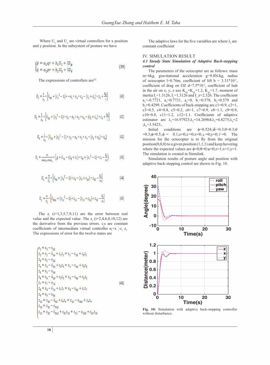
Simulation results of posture angle and position with adaptive back-stepping control are shown in Fig. 10.
Fig. 10: Simulation with adaptive back-stepping controller without disturbance.
Engineering of Science and Military TechnologiesVolume (1) - Issue (1) - 2017
19
Simulation results in Fig. 10 indicate that the octocopter can fly from original place to a given place and remain at hovering within five seconds when the error is less than 2%.
4.2 Shooting disturbance calculation and simulation
4.2.1 One shot simulation As mentioned in the objective, the main disturbance
in this simulation is shooting. A paintball gun is chosen to connect to the octocopter via a gimbal. First, we need to analyze and simulate the shooting. The momentum caused by the recoil is
Where the mb is the mass of bullet, vb is the bullet's original velocity shot out and N is the number of bullets. The force of recoil is
Where tb is the time of one shot. The integrator gives us the magnitude of force linearly varies with time during one shot
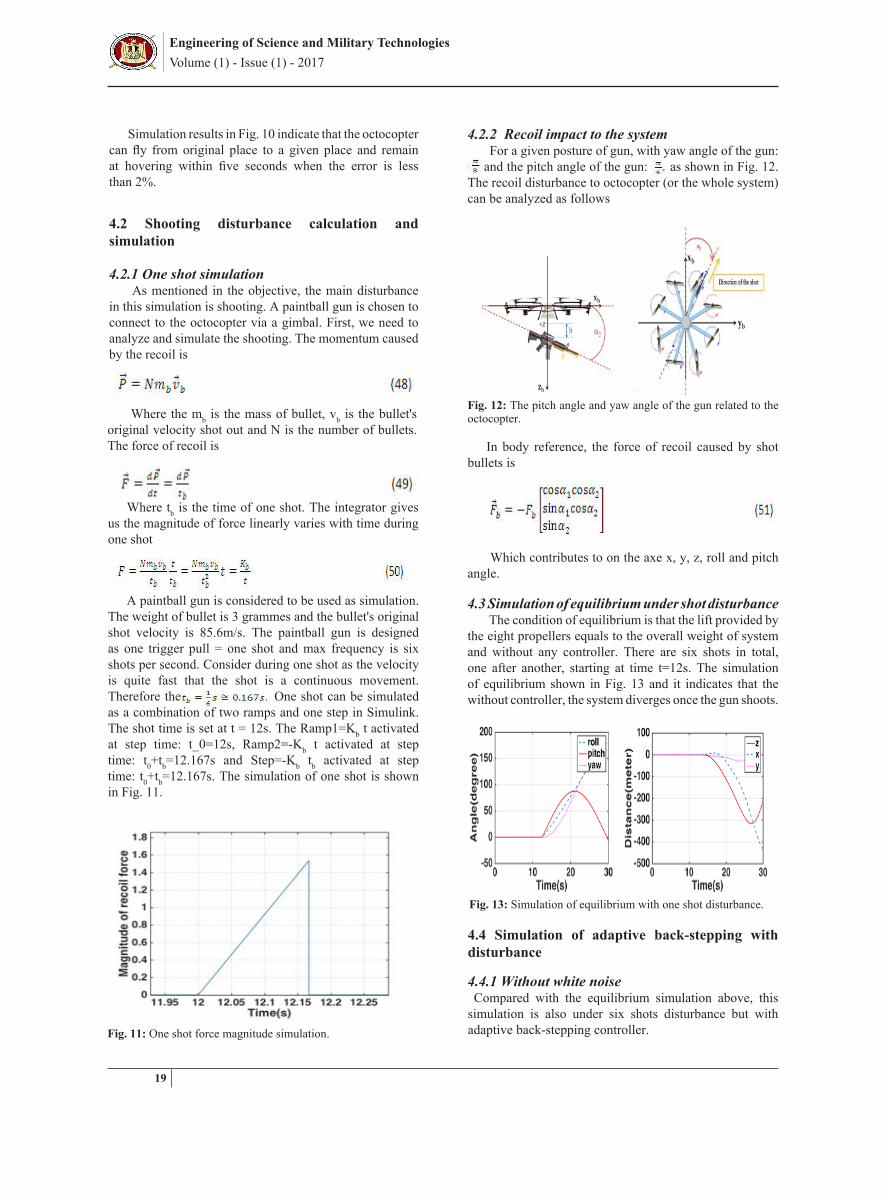
A paintball gun is considered to be used as simulation. The weight of bullet is 3 grammes and the bullet's original shot velocity is 85.6m/s. The paintball gun is designed as one trigger pull = one shot and max frequency is six shots per second. Consider during one shot as the velocity is quite fast that the shot is a continuous movement. Therefore the One shot can be simulated as a combination of two ramps and one step in Simulink. The shot time is set at t = 12s. The Ramp1=Kb t activated at step time: t_0=12s, Ramp2=-Kb t activated at step time: t0+tb=12.167s and Step=-Kb tb activated at step time: t0+tb=12.167s. The simulation of one shot is shown in Fig. 11.
Fig. 11: One shot force magnitude simulation.
4.2.2 Recoil impact to the system For a given posture of gun, with yaw angle of the gun: and the pitch angle of the gun: as shown in Fig. 12.
The recoil disturbance to octocopter (or the whole system) can be analyzed as follows
Fig. 12: The pitch angle and yaw angle of the gun related to the octocopter.
In body reference, the force of recoil caused by shot bullets is
Which contributes to on the axe x, y, z, roll and pitch angle.
4.3 Simulation of equilibrium under shot disturbance The condition of equilibrium is that the lift provided by
the eight propellers equals to the overall weight of system and without any controller. There are six shots in total, one after another, starting at time t=12s. The simulation of equilibrium shown in Fig. 13 and it indicates that the without controller, the system diverges once the gun shoots.
Fig. 13: Simulation of equilibrium with one shot disturbance.
4.4 Simulation of adaptive back-stepping with disturbance
4.4.1 Without white noise Compared with the equilibrium simulation above, this simulation is also under six shots disturbance but with adaptive back-stepping controller.
GuangXue Zhang and Haithem E. M. Taha
20
Fig. 14: Simulation of adaptive back-stepping controller with six shots disturbance.
As shown in Fig. 14, the max pitch angle that octocopter reacted is 0.1147 rad or 6.572 degree. The overshoot in pitch is 11.47% compared with final value of zero. The max roll angle is 0.0472 rad or 2.7 degree. The overshoot of roll is 4.7%. The response time of less than 2% error is 15.28-12=3.28s. On the other hand, the octocopter's altitude and position have very good performance that in the simulation, the overshoot is under 2%.
4.4.2 Simulation with white noise In order to mimic the real situation, a white noise is
considered to add in the shot simulation. The magnitude of white noise is 0.003.
Fig. 15: Simulation of adaptive back-stepping controller with six shots disturbance and white noise.
Compared with the simulation result without white noise, the curves in these Fig. 15 are rougher, especially in the posture angle. The position and altitude still remain very stable.
4.5 Simulation of adaptive back-stepping with shot disturbance and compensator
Despite the random white noise, the shot disturbance is considered to be given by the octocopter via a servo motor with the gun trigger. By giving the shot order, the recoil can be estimated and calculated in advance. So that in the estimator, we can compensate this potential shot recoil. As the simulation results indicate that the shot impact to altitude and position is negligibly small, here we focus on the attitude simulation. In order to illustrate the
performance of compensator, we first simulate the posture angle under shot disturbance with initial condition of roll, pitch and yaw angle are equal to zero, as shown in Fig. 16 left. The simulation with compensator is in Fig. 16 right.
Fig. 16: Simulation of adaptive back-stepping controller with zero initial conditions, using compensator with six shots disturbance and white noise.
The comparison in Fig. 16 shows that using the compensator helps to decrease of the pitch's overshoot and of the roll's overshoot. It proves that this compensator reduces significantly the impact of six shots.
4.6 Simulation of propellers' angular velocities and power dissipation
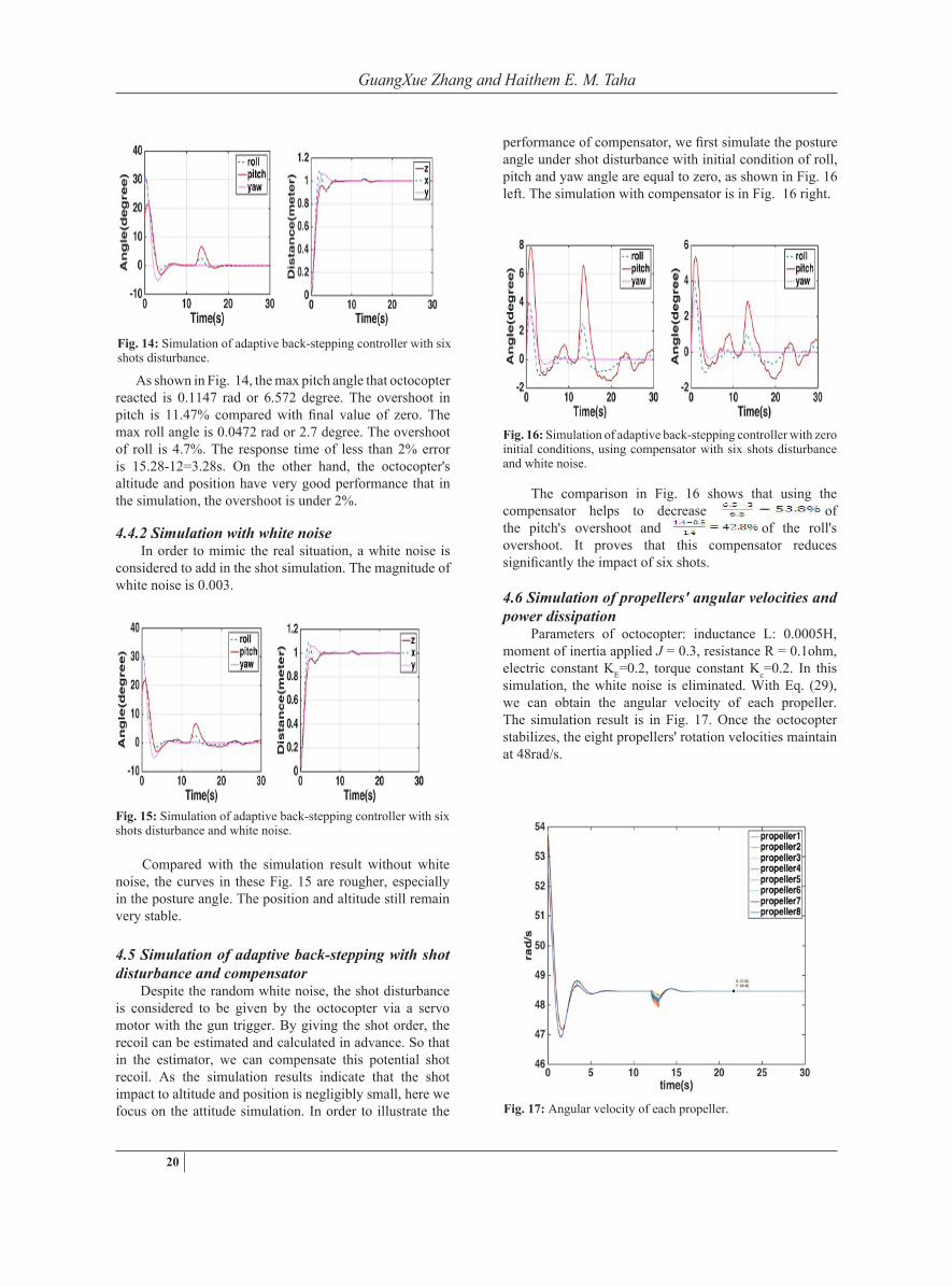
Parameters of octocopter: inductance L: 0.0005H, moment of inertia applied J = 0.3, resistance R = 0.1ohm, electric constant KE=0.2, torque constant Kc=0.2. In this simulation, the white noise is eliminated. With Eq. (29), we can obtain the angular velocity of each propeller. The simulation result is in Fig. 17. Once the octocopter stabilizes, the eight propellers' rotation velocities maintain at 48rad/s.
Fig. 17: Angular velocity of each propeller.
Engineering of Science and Military TechnologiesVolume (1) - Issue (1) - 2017
21
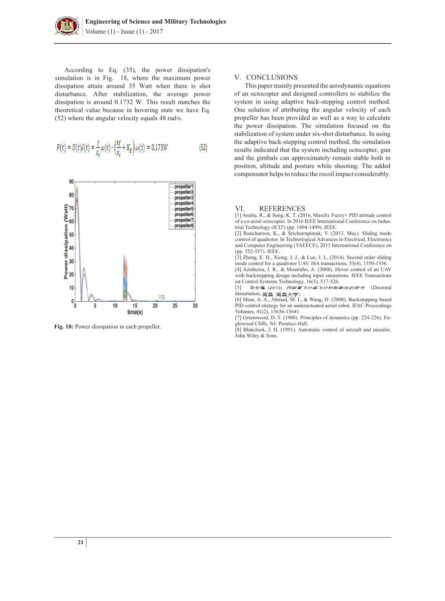
According to Eq. (35), the power dissipation's simulation is in Fig. 18, where the maximum power dissipation attain around 35 Watt when there is shot disturbance. After stabilization, the average power dissipation is around 0.1732 W. This result matches the theoretical value because in hovering state we have Eq. (52) where the angular velocity equals 48 rad/s.
Fig. 18: Power dissipation in each propeller.
V. CONCLUSIONS This paper mainly presented the aerodynamic equations
of an octocopter and designed controllers to stabilize the system in using adaptive back-stepping control method. One solution of attributing the angular velocity of each propeller has been provided as well as a way to calculate the power dissipation. The simulation focused on the stabilization of system under six-shot disturbance. In using the adaptive back-stepping control method, the simulation results indicated that the system including octocopter, gun and the gimbals can approximately remain stable both in position, altitude and posture while shooting. The added compensator helps to reduce the recoil impact considerably.
VI. REFERENCES[1] Analia, R., & Song, K. T. (2016, March). Fuzzy+ PID attitude control of a co-axial octocopter. In 2016 IEEE International Conference on Indus-trial Technology (ICIT) (pp. 1494-1499). IEEE.[2] Runcharoon, K., & Srichatrapimuk, V. (2013, May). Sliding mode control of quadrotor. In Technological Advances in Electrical, Electronics and Computer Engineering (TAEECE), 2013 International Conference on (pp. 552-557). IEEE.[3] Zheng, E. H., Xiong, J. J., & Luo, J. L. (2014). Second order sliding mode control for a quadrotor UAV. ISA transactions, 53(4), 1350-1356.[4] Azinheira, J. R., & Moutinho, A. (2008). Hover control of an UAV with backstepping design including input saturations. IEEE Transactions on Control Systems Technology, 16(3), 517-526.[5] (Doctoral dissertation, .[6] Mian, A. A., Ahmad, M. I., & Wang, D. (2008). Backstepping based PID control strategy for an underactuated aerial robot. IFAC Proceedings Volumes, 41(2), 15636-15641.[7] Greenwood, D. T. (1988). Principles of dynamics (pp. 224-226). En-glewood Cliffs, NJ: Prentice-Hall.[8] Blakelock, J. H. (1991). Automatic control of aircraft and missiles. John Wiley & Sons.