(adaptive) computed torque control of (flexible) …adaptive) computed torque control of (flexible)...
TRANSCRIPT

(Adaptive) computed torque control of (flexible) robotsystemsLammerts, I.M.M.
Published: 01/01/1990
Document VersionPublisher’s PDF, also known as Version of Record (includes final page, issue and volume numbers)
Please check the document version of this publication:
• A submitted manuscript is the author's version of the article upon submission and before peer-review. There can be important differencesbetween the submitted version and the official published version of record. People interested in the research are advised to contact theauthor for the final version of the publication, or visit the DOI to the publisher's website.• The final author version and the galley proof are versions of the publication after peer review.• The final published version features the final layout of the paper including the volume, issue and page numbers.
Link to publication
Citation for published version (APA):Lammerts, I. M. M. (1990). (Adaptive) computed torque control of (flexible) robot systems. (DCT rapporten; Vol.1990.063). Eindhoven: Technische Universiteit Eindhoven.
General rightsCopyright and moral rights for the publications made accessible in the public portal are retained by the authors and/or other copyright ownersand it is a condition of accessing publications that users recognise and abide by the legal requirements associated with these rights.
• Users may download and print one copy of any publication from the public portal for the purpose of private study or research. • You may not further distribute the material or use it for any profit-making activity or commercial gain • You may freely distribute the URL identifying the publication in the public portal ?
Take down policyIf you believe that this document breaches copyright please contact us providing details, and we will remove access to the work immediatelyand investigate your claim.
Download date: 12. May. 2018

(Adaptive) computed torque control of ( f l d b k ) r û b t system - I.
Ivonne M.M. Lammerts 1990
T.U.E. W.F. W.- rapport 90.063
December 1990.
Technical University Eindhoven. Faculty of Mechanical Engineering. Fundamental Mechanical Engineering.
Research project: A d v a n d control concepts
Control group of: for nonlinear flexible mechanical systems. Pro$ dr. ir. J.J. Kok, Dr. ir. F.E. Veldpaus.

(ADAPTIVE) COMPUTED T O R Q U E C O N T R O L OF (FLEXIBLE) R O B O T SYSTEMS
Summary
A mechanical manipulator can be defined as a multi degrees of freedom open-loop chain of mechanical linkages interconnected by joints. This mechanism, driven by actuators at the joints, is capable of moving the object at the end of the robot arm along a pre- scribed trajectory in space. To implement high-performance control, even when the ma- nipulator dynamics are poorly known or when large and unpredictable variations occur, adaptive control is considered, being a process of modifying one or more parameters of the structure of the control system and/or the control actions so as to force the re- sponse of the closed-loop system towards a desired one. Among various types of adaptive robot control systems, the M o d e l Reference Adaptive Contro l (MRAC) systems are important since they lead to relatively easy-to-implement systems with a high speed of adaptation and can be used in a variety of situations. However, it turns out to be difficult to derive convergence, stability and robustness conditions and it is hoped that a more unified framework for choosing an adaptation algorithm will be developed in future.
For an orientation in the field, five MRAC methods in literature are investigated. At- tention is focussed on the adaptive sliding controller of Slotine and Li [1987], in which the robot nonlinearities are compensated by feedback control. The model parameters are estimated on-line by an adaptation algorithm, based on the hyperstability theorem of Popov [1969]. This theorem offers a systematic solution to the stability problem, while Lyapunov's second method requires the (probably difficult) choice of an appropriate func- tion candidate. In order to assure robustness in the presence of model uncertainties and (environmental) disturbances, a sliding control term is incorporated into the control input.
Today, industrial robots are used for various purposes. Because of hardware limitations in on-line applications, until now, robot control has been studied extensively under the assumption that the actuator transmissions are stiff and that the links can be modeled as rigid bodies. Therefore, most of today's robots have a very stiff (and thus heavy) construction in order to avoid deformations and vibrations. For higher operating speeds, industrial robots should be lightweight constructions to reduce the driving force/torque requirements and to enable the robot arm to respond faster. However, a lightweight ma- Iliyulaior- *Iïay hav.ie fieSbi&y in & liï& s.r-üci-üre and el:asticiiy in the trasisulissiuiis L-&-..--- ..-&.-a+-..- ..-A 1:-1-- va.. ---+ -..* :....l..+-.." ,.l.."+:,.:+.. -4-+L#. mA+-,. +,...,,,:,,:,,, u e b w e e l l Q . L b U & b U l U &11U l l l l h U . L U I l l l U 3 b l l l a l l l l p u l a b u l U , G l a U b l L l b y u1 b l l G 1 l l U b U l b L a ~ U u l l U U l u l L U
has a greater significance for the design of the controller than the deformation of the flex- ible links. Furthermore, link flexibility can be approximately modeled by a chain of rigid sublinks interconnected by elastic joints. Hence, more accurate models involving elastic transmissions should be taken into account to pursue better dynamic performance of in- dustrial robots. The application of more complex control algorithms is possible now due to the availability of advanced multiprocessor equipment for real-time manipulator control.
1

Eindhoven
*1- '2. '3' '4' :5'
Contents:
MRAC scheme of Landau. MRAC scheme of Horowitz and Tomizuka. MRAC scheme of Craig, Hsu and Sastry. The TR-robot. The desired trajectory.
T.U.E. Ivome Lammerts WrFW 90.063
A MRAC CONTROL OF MANIPULATORS - a short review of 5 methods.
A.1 The dynamic model of a robot manipulator. A.2 Computed torque control. A. 3 AdaDtive manipulator control.
A. 3.1 Landau. A. 3.2 Horowitz and Tomizuka. A. 3.3 A. 3.4 Sadegh and Horowitz. A. 3.5 Slotine and Li.
Craig, Hsu and Sastry.
A.4 Lyapunov's second method.
A.5 Figure
A. 6 Plots with simulation results.
A-1 A-2 A-3
A-4
A-5
A-6
A-?'
A-8
A-9 !
A-10
B ON THE ADAPTIVE CONTROL OF ROBOT MANIPULATORS - Slotine and Li.
B. 1 Introduction. B.2 AdaDtive commted toraue controller with PD feedback. B. 3 Elimination of the steady-state position errors.
B. 3.1 Sliding controller. U. R O B U. u
B.4 Plots with simidation results. Satsturatlon controller.
B-1 B-3 54
B-7
&i 3 1
C CONTROL OF FLEXIBLE MANIPULATOR.
C. i Introduction. C.2 Rigid manipulator control. C. 3 Flexible manipulator control. c. 3. i
C. 3.2 Adaptive control. c. 3.3 Sliding control.
Computed torque control.
G-1
G-2
G 3
D GENERALIZED COMPUTED TORQUE CONTROL OF A FLEXIBLE MANIPULATOR.
D. i Maniipullitûï dynamics. D. 2 D. 2.1 Manipulator control.
D. 2.2 Computed torque control. D. 3 Computed torque control with desired output. D.4 Generalized computed torque control. D.5 Computed torque with sliding control. D. 6 Computed torque control.
D. 6.1 Computed torque control
D. 6.2
D. 6.3
- with a full reference trajectory. The TR-robot with one flexible link - an example. Adaptive computed torque control - with a full reference trajectory.
D-i
0-3 LI-6
D-Y
0-8
E TWO-TIME SCALE SLIDING CONTROL OF A FLEXIBLE MANIPULATOR - Slotine and Hong.
E. i Introduction. E. 2 Manipulator dynamics - in singular perturbation formulation.
E.3 Desim of the slow sliding controller. E.4 Design of the fast sliding controller.
E-i E-2
&3 s 4
! E-6

F JADAPTTVE) TWO-SUBMODEL BASED COMPUTED TORQUE CONTROL OF FLEXIBLE ROBOT SYSTEMS.
F. 1 Introduction. F.l.1 F.1.2 F.1.3
F-1 The flexible manipulator system. Two submodels. F-2 Two-submodel based (adaptive) flexible robot control.
F.2 The flexible manipulator system. F.3 Rigid computed torque control.
F.3.1 Sliding control term. F.4 Flexible conmuted toraue control.
F.4.1 Reformulation. F.5 Stability of the overall control system. F. 6 Adaptive flexible ccqxtec! torque control.
F. '7 F. 7.1 F. 7.2 F. 7.3
Conclusions. Future research. References.
F-3 F-4
F-5 F-6 F-7 F-8
F-9
G 3 Degres-of4eedom (DOF) elastic-ioint Translation-Rotation (TR-) robot with 2 motor input signals.
G.1 Model of the 3DOF elastic-joint TR-robot. G.2 2DOF rigid TR-robot.
G. 3 3DOF elastic-joint TR-robot.
G. 2.1 PID control. G. 2.2
G. 3.1 G. 3.2
Rigid computed torque control.
Rigid computed torque control. Flexible comwted toraue control:
G. 3.2.1 G. 3.2.2
G. 3.2.3 G. 3.2.4
G.4 Control simulation results - on the 3DOF elastic-joint TR-robot.
G. 5 Anaiysation of the control simuiaiion results. T-l- G.6 pigrnes,
G-o G-1
G-2 G-3 G-4 G-6
G-7
c-8 Gl o
1 G-17

Inleiding
Het project 'Geavanceerde regelconcepten voor niet-lineaire flexibele mechanische syste- men' heeft tot doel het ontwikkelen van concepten voor het on-line regelen van niet- lineaire mechanische systemen en heeft als uitgangspunt een model van die systemen. In dat model wordt rekening gehouden met onzekerheden ten aanzien van (eventueel in de tijd variërende) systeemparameters, met elastische vervormingen en met speling en wrijv- ing. Klassieke concepten uit de lineaire regeltheorie (PID-regelaars, optimale regelaars, etc.) zijn niet zondermeer bruikbaar en derhalve worden momenteel nieuwe technieken ontwikkeld. De in het vervolg met 'Computed Torque ControF aangeduide methodes zijn gebaseerd op vereenvoudigde modellen van de te regelen systemen. Beschouwd worden mechanische systemen waarvan de onderdelen t.o.v. elkaar grote verplaatsingen en ver- draaiingen kunnen ondergaan. Bij dit onderzoek wordt in het bijzonder de aandacht gericht op mechanische manipulatoren die een object langs een vooraf bepaalde gewenste baan in de ruimte dienen voort te bewegen.
Adaptive Computed Torque Contro l voor s t i j v e manipulatoren m e t parametr i s che onzekerheden
In eerste instantie worden de manipulator-elementen stijf verondersteld. Daarnaast wordt aangenomen dat enkele van de systeemparameters, zoals bijvoorbeeld de massa van de last aan het uiteinde van de robotarm, onbekend zijn of eventueel zelfs variëren in de tijd. De taak van een 'Adaptive Computed Torque Control' systeem is dan om on-line de parameters van het regelmodel te schatten, zodanig dat het geregelde systeem de gewenste baan toch zo goed mogelijk volgt (dus binnen bepaalde marges).
In dit rapport worden vijf adaptieve regelconcepten vergeleken aan de hand van simu- laties op een translatie-rotatie (TR) robot (hoofdstukken A en B). De verkregen resultaten zijn bevredigend, maar werpen niet meer licht op de achtergornd van de (verschillen in) deze methodes. Er is wel een algemene aanpak zichtbaar waarbij computed torque control wordt toegepast. In die aanpak worden de model parameters on-line geschat, zodanig dat het geregelde systeem de gewenste trajectorie zo goed mogelijk volgt. De zgn hypersta- biliteitstheorie van Popov [1969], waarop deze methode is gebaseerd, blijkt meer ruimte te scheppen voor het ontwerpen van adaptieve regelingen dan de condities verkregen vol- gens de meer bekende methode van Lyapunov. Dit opent de weg naar het formuleren van adaptieve regelconcept en voor flexibele manipulatoren.
Geavanceerde rege lconcepten voo r f lexibele manipulatoren
T7 vanaÎ hooÎ~siuk C iigi hei accent op het niët-adaptief regelen üü'n flezlkele .7iziiil~lpul~iû~re~n.
groter dan het aantal ingangssignalen op de motoren die de robot-elementen ten opzichte van elkaar doen bewegen. Dit levert regelproblemen op die ook door adaptieve regelingen, ontworpen voor stijve manipulatoren, niet kunnen worden opgevangen: simulaties van de eerder gebruikte adaptieve regelingen op dezelfde TR-robot , nu echter met een elastische arm, leiden tot instabiliteiten in het geregelde gedrag. Daarom moet allereerst gezocht worden naar methodes voor het ontwerpen van stabiele regelingen voor flexibele mecha-
goor 'sb& opireden van elasi;.sehe vr@eidsgraden het totde vr;ji;he;dsgradeii
3

nische systemen zonder dynamische onzekerheden.
*) General i zed computed torque control
Heeren [1989] heeft een voorstel gedaan voor een computed torque control versie waarbij, via een zekere vorm van optimalisering ten aanzien van de ingang, getracht wordt alle vrijheidsgraden en tevens de motorkrachten/-koppels binnen bepaalde grenzen te houden (hoofdstuk D). Daarmee wordt voorkomen dat er een ongewenst grote divergentie van deze signalen optreedt, maar enige garantie ten aanzien van de stabiliteit van het resulterende systeemgedrag ontbreekt.
*) Sliding computed torque control m e t s tab i l i zer
Aan de sliding computed torque regelaar van Slotine en Li 619863 (hoofdstuk B) kan een regelterm worden toegevoegd ter stabilisatie van de optredende elastische oscillaties. Een aanzet daartoe is beschreven in paragraaf D.5. Daarbij wordt gebruik gemaakt van de 'Variable Structure Systems' (VSS) theorie volgens Utkin [1977]. Deze aanpak heeft tot doel het uitdempen van de optredende elastische trillingen in het systeem, hetgeen bij slappe elementen een heel onnatuurlijk gedrag van het systeem tot gevolg kan hebben.
*) T w o - t i m e scale computed torque control
Een zeer in het oog springend alternatief wordt gegeven in het artikel van Slotine en Hong [1986] (hoofdstuk E). Daarbij wordt niet getracht om de flexibele bewegingen volledig te dempen, maar wel om deze te leiden naar een natuurlijker ogend gedrag (de zgn 'mani- fold')? dat bij benadering kan worden afgeleid uit de bewegingsvergelijkingen van het flexi- bele systeem door te lineariseren volgens de 'Singular Perturbation Technique' (Khorosani en Spong [1985], Marino en Nicosia [1984]). E r zijn overeenkomsten te bespeuren met de sliding control-methode van Asada en Slotine [1986], in die zin dat er met een toegevoegde regelterm allereerst gepoogd wordt de flexibele vrijheidsgraden te laten convergeren naar die manifold als zgn. 'switching surface', waarna vervolgens de rest van het systeem, het niet-flexibele gedeelte, als vanouds wordt geregeld om de overige 'stijve' vrijheidsgraden de gewenste trajectorie te laten volgen. Slotine en Hong gebruiken daarbij een regeling volgens de reeds vermelde 'sliding computed torque control' methode van Slotine en Li. E r kan waarschijnlijk evengoed een andere regeling op los gelaten worden.
*) (Adap t i ve ) C o m p u t e d Torque Cont ro l van de f l e d e l e manipu la tor opgespl i ts t in twee dee l sy s t emen
slet is in hoof&t,uk F het idpp Gitgrwerkt waarbi; J -- hPwPgingr~ergeli~~ingen --"- vzn het flexibele manipulator systeem opgesplitst worden in twee deelsystemen (enerzijds de stijve robot-elementen en anderzijds de aandrijvingen), onderling gekoppeld door de elastis- che verbindingskrachten. Op beide deelsystemen kan vervolgens een vorm van computed torque control worden toegepast, waarbij elastische referentie-verbindingskrachten worden gedefinieerd die het gewenste volggedrag van de stijve robot-elementen tot gevolg kun- nen hebben, mits de stabiliteit van beide geregelde deelsystemen in onderlinge samenhang gegarandeerd is. De motor-ingangssignalen worden bepaald, zodanig dat de optredende
4

elastische verbindingskrachten zoveel mogelijk overeenkomen met deze referentiekrachten. De uitbreiding naar adaptief regelen in geval van model-onzekerheden via deze methode wordt kort aangehaald. In eerste instantie wordt getracht volgens de methode van Lya- punov globale stabiliteit te verkrijgen (niet-adaptief); een voor de hand liggend alternatief is de hyperstabiliteitstheorie van Popov (adaptief). Simulatie-resultaten, verkregen bij het regelen van een translatie-roatatie robot met een elastische verbinding tussen de motor en de roterende arm, worden besproken in hoofdstuk G.
Slotopmerking
Verder onderzoek op dit gebied zal vooralsnog fundamenteel van karakter zijn om zodoende te komen tot een basis voor het ontwikkelen van (adaptieve) regelstrategieën voor flexibele manipulatoren. Dit fundamenteel getinte werk zal worden ondersteund door uitwerkingen via simulaties. Op de langere termijn wordt beoogd enkele geselecteerde strategieën voor toetsing aan de praktijk te realiseren op een experimentele xy-tafel.
Referenties
* Asada, H. and Slotine, J.-J.E. (1986) Robot analysis and control. John Wiley 63 Sons,
On Control of manipulators.
* Khorosani , K. and Spong, M.W.
* Heeren, T.A.G. (1989)
ISBN 90-9002789-0. (1985)
Invariant manifolds and their application to robot manipulators with flexible joints. IEEE Int. Conf. on Robotics and Automation, St. Louis.
Model Reference Adaptive Control of manipulators - Orientation and two methods. WF W-rapport nr. 89.033, TUE, Eindhoven.
On the feedback control of industrial robots with elastic joints: a singular perturbation approach. University of Rome, R-84.01.
n y y ei b ~ a . ~ i i i by ui LULLLI ui by b ~eiiib.
* Slotine, J.-J.E. and Hong, S.
* Lammerts , I.M.M. (1989)
* Marino, R. a n d Nicosia, S.
* Popov, V.M. TT--- ---L. - 1. !l!~.-- -i _ _ _ ~ ~ - 1 ---- L -- - AT-... V--L I?--: -e-+. T7,,1..,. IVGW í U I I L , J ~ l J l ú l ú L J G i - V C l ú U l J .
Two-time scale sliding control of manipulators with flexible joints. American Control Conference, DSE: DPC 82 AME.
Sliding modes and their applications to Variable Structure Systems.
* Utkin, V.I.
(1984)
(1969)
(1986)
(1977)

A- O
MRAC CONTROL OF MANIPULATORS.
A short review of 5 methods:
1. Landau, Y.D. Adaptive control: the model reference approach
(1979)
Marcel Dekker, New York, ISBN 0-824 7-654s-6.
2. Horowitz, R. and Tomizuka, M. (1980) An adaptive control scheme for mechanical manipulators - compensation of nonlinearity and decoupling control.
IISiWB-paper, no. 8- kVA/ DSG6, Winter Annual Meeting, Chicago.
3. Craig, J.J., Hsu, P. and Sastry, S.S. (1 986) Adaptive control of mechanical manipulators.
Proc. ofIEEE Intl. Conf: on Robotics and Automation, San Francisco.
4. Sadegh, N. and Horowitz, R. (1 987) Stability analysis of an adaptive controller for robotic manipulator.
Proc. of IEEE Intl. Con$ on Robotics and Automation, San Francisco.
5. Slotine, J.-J. E. and Li, W. On the adaptive control of robot manipulators.
(1 986)
ASME Winter Annual híeeting, Anaheim, Dec.

tue-wfw-i1
is the is the is the is the is the is the
a- i
nxl vector of joint displacements (revolute/translational), 'nxl' vector of joint velocities, nxl vector of joint accelerations, ' n x l ' vector of applied joint forces/torques, 'nxn symmetric,positive definite inertia matrix, :nxli vector of Coriolis and centrifugal forces/torques:
4.1 THE DYNAMIC MODEL OF A ROBOT MANIPULATOR.
A manipulator is modeled as an open chain of n moving rigid bodies (links) interconnected by cylindrical, revolute or prismatic joints of one degree of freedom, with one end fixed to the qound and the other end free. The actuator forces/torques acting on the joints are the inputs, whereas the joint coordinates represent the outputs.
In the absence of friction, gravity or other disturbances, the dynamic model of a robot maniniilator can be written as:
Equation (i) can be translated into the next state variable differential equation:
Although the equations of motion are complex, nonlinear equations for all but the simplest robots, they have several fundamental properties which can facilitate control system design. It is assumed that the kinematic structure of the manipulator is known, but that the numerical values of some or all of the dynamic robot parameters (such as link masses, moments of inertias, etc.) are unknown. Now, one fundamental property of robot dynamics is that these parameters of interest appear as coefficients in a linear relationship of kr,=wn h c t i o n s ef the generu!ized com!inôtes, sa that wo may write the dynamic eqQat,i^ns (i) 2s:
M(da + C(s,l!)x = W(Q,Y,a)l, (3), where
is a [rxl] vector containing known/unknown parameters, W(g,x,a) is a [na ] matrix of known functions.

tue-wfw-i1
0.2
A -2
COMPUTED TORQUE CONTROL.
Computed torque control schemes rely on exact compensation of all nonlinearities in the manipulator system, so that, in the ideal case, the closed-loop system is linear and decoupled.
Using a structure identical to that of the dynamics of the manipulator, the control inwt i s chosen as:
9 = M(g)ll r + C(s,J$! (4).
Then, by substituting (4) into (1), the problem is reduced to that of controlling the simple system:
- a = g (5), t
since the inertia matrix M is positive definite and therefore invertible.
Expression (5), in turn, represents a set of n decoupled double-integrators, each of which can be controlled independantly by an outer-loop control law with units of the desired acceleration ad(t). This can be defined in terms of a given linear dynamic compensator K(s) as:
- u r = -d a -K(s)g (0 where g(t) = g(t)-qd(t).
Substituting (6) into (5) leads to the linear error equation: [ s21 + K(s) ]e = 0.
The simplest choice of K(s) in (6) is a PD-compensator: K(s) = K s + K , ë + K e + K e = Q.
If the gain matrices K, and K, are chosen as diagonal matrices with positive diagonal elements, then the closed-loop system is linear, decoupled and globally stable.
V P
P- which leads to the familiar second order error equation: -
V
instead of (4), so that we get the closed-loop dynamics
instead of (5).
Expression (8 shows that the problem is not as simple as 5) looked, and in particular may not be a d equately handled by standard linear control tec h niques.
tue-wfw-i1
A.3 A D A P T m MANIPULATOR CONTROL.
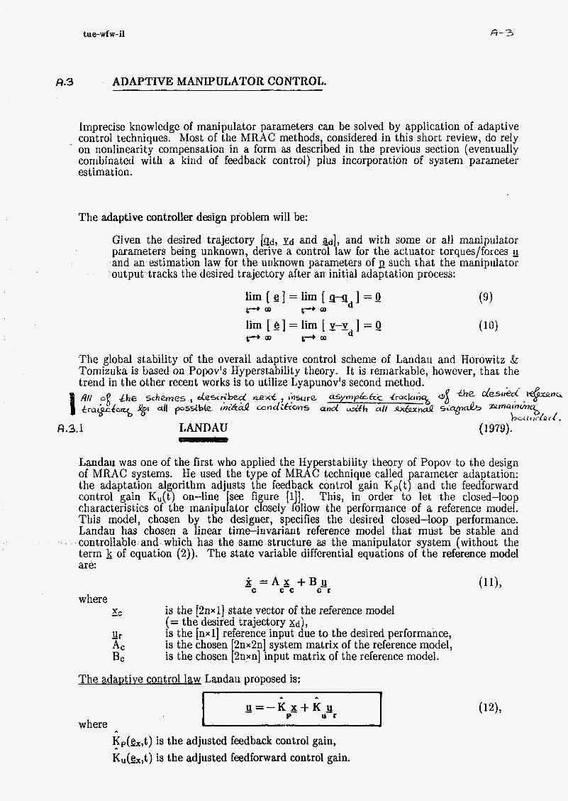
Imprecise knowledge of manipulator parameters can be solved by application of adaptive control techniques. Most of the MRAC methods, considered in this short review, do rely on nonlinearity compensation in a form as described in the previous section (eventually combinated with a kind of feedback control) plus incorporation of system parameter estimat ion.
The adaptive controller design problem will be:
Given the desired trajectory [&, yd and ad], and with some or all manipulator parameters being unknown, derive a control law for the actuator torques/forces Q
and an estimation law for the unknown parameters of I> such that the manipulator output tracks the desired trajectory after an initial adaptation process:
The global stability of the overall adaptive control scheme of Landau and Horowitz SC Tomizuka is based on Popov's Hyperstability theory. It is remarkable, however, that the trend in the other recent works is to utilize Lyapunov's second method. flff og &,e s c h e ~ n e ç describecc' nexf insure. asympAtrc 4ruckrh~ tr&&c% % all p o s s i b k ihi&Q c o n d i G o n ~ and U& al/ ~ & n & S L ~ ~ ~ L . & J
û.3.1 LANDAU (1979).
t h e desrkd +nc,
bct i u<-&< i e
Landau was one of the first who applied the Hyperstability theory of Popov to the design of MRAC systems. He used the type of MRAC technique called parameter adaptation: the adaptation algorithm adjusts the feedback control gain Kp(t) and the feedforward control gain K,(t) on-line see figure [i 1. This, in order to let the closed-loop
This model, chosen by the designer, specifies the desired closed-loop performance. Landau has chosen a linear time-invariant reference model that must be stable and controllable and which has the same structure as the manipulator system (without the term k of equation (2)). The state variable differential equations of the reference model are:
characteristics of the manipu I ator closely f' ollow the performance of a reference model.
- X = A x + B Q C c c C K
.,...here -v L.
Ur
is the [anxi] state vector of the reference model (= the desired trajectory &d), is the [nxl) reference input due to the desired performance, is the chosen 2nx2n] system matrix of the reference model, is the chosen t 2nxn] input matrix of the reference model.
Ac Bc
The adaDtive control law Landau proposed is:
where
I * I i u = - K x + K
P- U K
Kp(gx,t) is the adjusted feedback control gain, K,(g,,t) is the adjusted feedforward control gain.
tue-wfw-i1
,. ,.
U = M ( Q ) ~ + - F 5 - F fj c p c v c
where %(t) = d t ) - sc(t>, &(t) = 10) - &),
A- 4
(141%
6.3.2 HOROWITZ AND TOMIZUKA 4
r
(1980).
t Kigdr-K P- e-K V fj
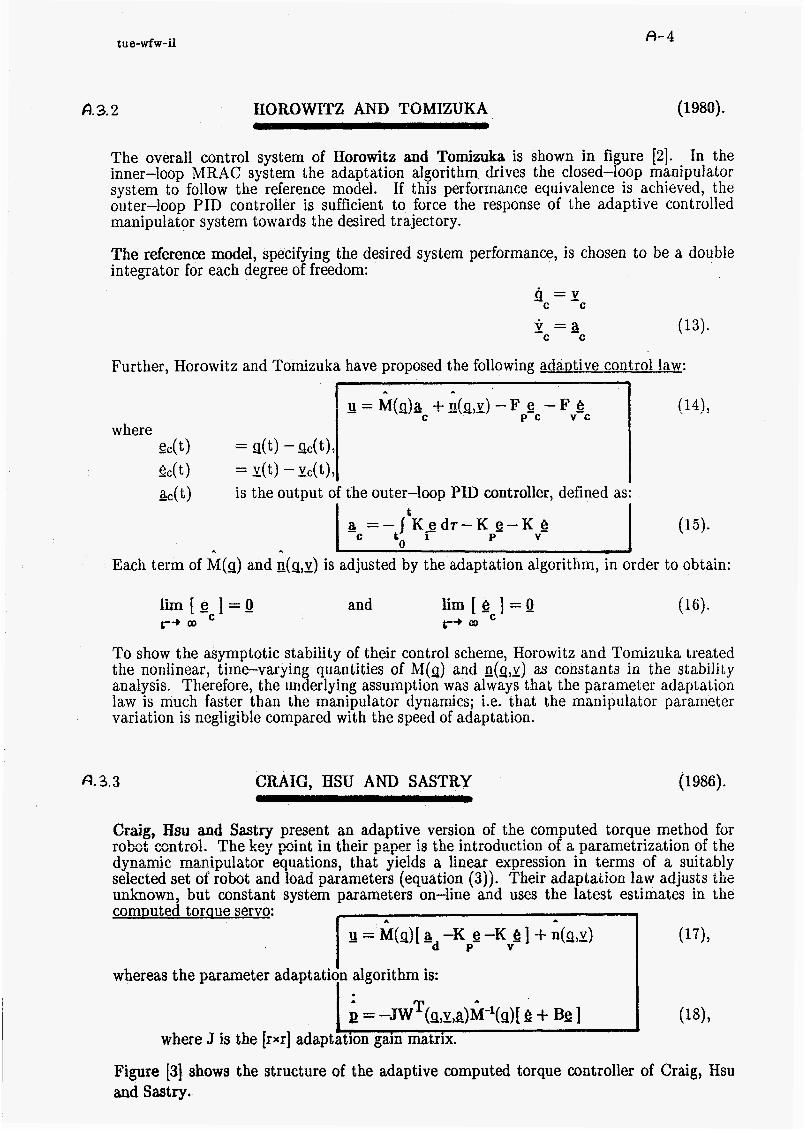
The overall control system of Horowitz and Tomizuka is shown in figure [2]. In the inner-loop MRAC system the adaptation algorithm drives the closed-loop manipulator system to follow the reference model. If this performance equivalence is achieved, the outer-loop PID controller is sufficient to force the response of the adaptive controlled manipulator system towards the desired trajectory.
The reference model, specifying the desired system performance, is chosen to be a double integrator for each degree of freedom:
9 = y
- ir =a (13).
c c
c c
(15)-
Each term of M(q) and g(q,x) is adjusted by the adaptation algorithm, in order to obtain:
l i m [ g ] = o r+ C
and f i r n [ & ] = o C r+
To show the asymptotic stability of their control scheme, Horowitz and Tomizuka treated the nonlinear, time-varying quantities of M(q) and n(g,x) as constants in the stability analysis. Therefore, the underlying assumption was always that the parameter adaptation law is much faster than the manipulator dynamics; i.e. that the manipulator parameter variation is negligible compared with the speed of adaptation.
CL). 3.3 CRAIG, HSU AND SASTRY (1986).
Craig, Hsu and Sastry present an adaptive version of the computed torque method for r û b ~ t cmtrd. The key pirit iri their pper is the introduction of a parametrization of the dynamic manipulator equations: that yields a linear expression in terms of a suitably selected set of robot and ioad parameters (equation (3jj. Their adaptation law adjusis the unknown, but constant system parameters on-line and uses the latest estimates in the
whereas the parameter adaptation 1 algorithm is:
comDuted torque servo: u = Wil)[ ad -Kpg -K e 1 + n(s,x) (171,
where J is the frxr] adapthion gain matrix. J
Figure [3] shows the structure of the adaptive computed torque controller of Craig, Hsu and Sastry..

tue-wíw-i1 4-5
i. A A
u = M(da r + C(Q,Y)Y r - K h s (2517
(26), 1 -'T B = -J w (S,Y,Y ,a )a r r
I
A.3.4 SADEGH AND HOROWITZ ( 1987).
Refering to the trend in recent work of Crai , Hsu and Sastry (1986), Sadegh and
requirement of Horowitz and Tomizuka (1980), by reparametrizing t e nonlinear dynamic manipulator terms as linear functions of unknown but constant parameters (equation (3)), which will be estimated on-line by the parameter adaptation algorithm:
fl Horowitz have been able to remove the sowly P time-varyin system parameter
The new adaptive control la
where t
a = a - j K i g d ~ - K e - K & ' P- V
- c -d to
Comparing this with the method of Craig, Hsu and Sastry, in the algorithm (19j the acceleration input zic(t) is used instead of the joint accelerations -(t) in (18) (which are not measurable in most realistic applications) and no matrix inversion is required.
f3.35 SLOTINE AND LI (1986).
Craig, Hsu and Sastry (1986) have proposed a31 adaptive computed torque controller, which, however, requires acceleration measurements and the inversion of the matrix of estimated parameters. This problem is solved by Slotine and Li using a natural relationship between the inertia matrix and the Coriolis/centrifgal terms, namely that:
R = [ M-2C ] is a skew-symmetric matrix (i.e., that derived from the Lagrangian formulation of the manipulator dynamics .
T b=Q for all s7 and so rkj = -rek), as can be easily
This property enabled Slotine and Li to define the following adaptive law cq. adaptation algorithm: A
a = M(q)ad + C(Q,I)Yd - K P- e - K Y e (22) 7
tu e-wfw-i1 A-6
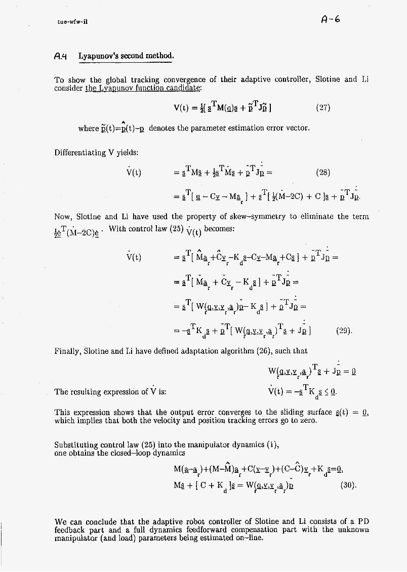
A.4 Lyapunov's second method.
To show the global tracking convergence of their adaptive controller, Slotine and Li consider the Lvanunov fiinction candidate:
V(t) = 2 gTM(q)9 + iTJE ] A
where E(t>=g(t)--Q denotes the parameter estimation error vector.
Differentiating V yields:
= sTM$ + kTMp + -T JQ - _ - -
Now, Slotine and Li have used the property of skew-symmetry to eliminate the term gT(M-2c)e . With control law (25) Q(t) becomes:
-
Finally, Slotine and Li have defined adaptation algorithm (26), such that
The resulting expression of V is:
This expression shows that the output error conver es to the sliding surface s(t) = 0, which implies that both the velocity and position trac a ing errors go to zero.
Substituting control law (25) into the manipuiator dynamics ( i j , one obtains the closed-loop dynamics
A
We can conclude that the adaptive robot controller of Slotine and Li consists of a PD feedback part and a full dynamics feedforward compensation part with the unknown manipulator (and load) parameters being estimated on-line.

I
I
A- ft
- x(t0)
MANIPULATOR - X
L!r
-
feed-
forward
control ADAPTATION 4
parameter ALGORITHA i <
adaptation
Figure [d 1: MRAC system of LANDAU.
L
b = ] ADAPTATION
ALCCRlTFM J I 1
4 REFERENCE MEEL I
V -
V -C

*~O~OJ uoqeioi uoiielsueii e
: W31SAS W3NINON 3Hi
I
L
I

Some simulation results with a translationiotation robot:
” t
., 8 I * I L 1 L * . 7 * t ,e
mr
î i
Tlic dcsircd trajcclory.
I Fixed-paramctcr con trol : Fgiires [6]) [?I aiid [SI.
Fì’iguI’e [SI:
- 11 = hf(g)sr +C!(g,y)J!,-I<& As T;‘ig.[b] but witli ar(t) instead of witli Q(I(t,):
[ K d = 1001. ” 1
.bs
.I.
11
I
**
b
*l
I
.I I . I S 8. I s . I 1. L * I*
I Y
I
U
.I.

Figur e [li]:
Figur e [12]:
Figur e [13]:
Figur e [14]:
Landau
A 4 0
[wol, 1 O.O. 0.01.
Horowitz & Tomizuka [g].
Craig [smto: i .O. i].
Sadegh & Horowitz (smt0:î .&i].
Figur e [15]:
-- ----- ............. -$Y:: 9' (4
Slotine & Li

3 ON THE ADAPTIVE CONTROL OF ROBOT MANIPULATORS
J.-J E. Slotine and W. Li
€ 5 0 9 INTRODUCTION.
A lobally stable adaptive controller for robot manipulators was presented in Craig et a1.(?986). The key point in that paper was the introduction of a parametrization of the robot equations that yields a iinear expression in terms of a suitably selected set of robot and load parameters. Based on this parametrization an adaptive computed torque controller was proposed. However, it required acceleration measurements and the inversion of the matrix of estimated parameters. Using a natural relationship between the inertia matrix and the Coriolis/centrifugal terms, this problem is solved by Slotine and Li (1986).
Slotine and Li have developed a globally asymptotically convergent adaptive controller to control manipulators under certain dynamic uncertainties. Their adaptive robot control algorithm consists of a proportional/differential (PD) feedback part and a full dynamics feedforward compensation part with the unknown manipulator and payload parameters being estimated on-line.
Dynamic model of a robot manipulator.
In the absence of friction or other disturbances,the dynamic model of a robot manipulator can be written as:
u = M(q)a + C(s,l!)y (1) where
- U is the Tn*ll vector of applied joint torques or forces? is the rn*l] vector of joint displacements,
M(g) is the ‘n*nl symmetric, positive definite inertia matrix, II(Q,I) is the /n*l.’/ vector of centrifugal, Coriolis
gravity and friction torques/forces.

Fundamental properties of manipulator dynamics.
Although the equations of motion (1) are complex, nonlinear equations for all but the simplest robots, they have several fundamental properties which can be exploited to facilitate control system design. Two of them are mentioned now:
*) First, Khosla et al. (1985) and Atkeson et al. (1985) have shown that all of the constant parameters of interest such as link masses, moments of inertias, etc., appear as coefficients of known functions of the generalized coordinates. By defining each coefficinet as a separate arameter, a linear relationship results so that we may write the dynamic equations P 1) as:
where M ( Q h + C(Q,X)I = W(s,J!,i)a (2)
Q is a [r*1] vector containin the unknown bu& cons*anf parameters 3
W(g,y,&) is a [n*rr] matrix o f known functions.
*) Second, as remarked by authors as Arimoto et al. (1984) and Koditschek (1984),
the matrix N = [ M-2C 3 is skew-symmetric (i.e., that 3 Nx=Q for all s, and so nkj = -n.k), as can be easily derived from the Lagrangian lormulation of the manipulator dynamics .
T
Controller design.
The controller design problem is as follows:
Given the desired trajectory, and with some or all manipulator parameters being unknown, derive a control law for the actuator torques/forces and an estimation law for the unknown parameters such that the manipulator output tracks the desired trajectory after an initial adaptation process.
Slotine and Li derive their controller in a few steps:
1.
2.
3.
4.
First, in section 1, a simple globally stable adaptive controller is obtained from the Lyapunov stability analysis. The controller strongly exploits the structure of the manipulator dynamics, pointed out in the previous section. However, the adaptive controller does yield zero velocity errors, but it may present nonzero position errors.
Slotine and Li solve this problem in section 2 by restricitng the residual tracking errors lie a $:&fig sUïface, +L..n n*.nnnnt n : n m CL(I ,-ntnt; n n n x r n r m n n r n nf t h o V l I u
trantinm b i U i L b nrrnr. UI I "I
ulua 6uaiaiitikiiib a.) i i i y u u u i c UULI v ~ I b u u U u
Further, in section 3, a sliding control term is incorporated into the control input to make the controller robust either to the uncertainty on parameters not explicitely estimated on-line and to residual time-varying disturbances (such as stiction),
Finally, the sliding control term is changed in section 4 into a sonamed saturation control term to avoid control chattering.

B.1 ADAPTIVE COMPUTED TORQUE CONTROLLER WITH PD FEEDBACK.
* *
a(t) = M(g)a (t) + C(g,y)v - K e - K e -d -d P- d-
To derive the control algorithm and adaptation law, Slotine and Li consider the Lyapunov function candidate
(5)
(3) T NT N T V(t) = g e M ( g ) e + ~ Jg+e K e ]
P- where
L
i(t)=e(t)-Q denotes the parameter estimation error vector, KP and J are r*r] symmetric positive definite matrices, usually diagonal, c(t)=Q(t)-d t t) is the tracking error.
Differentiating V yields:
V(t) = eTM(de/dt) + i[ e T M q t Q -T JQ + gTK e = P-
T T ' 'T T = e [IJ-Cy-Ma ] + e [i(M-2C)+C]&-t Q J Q + ~ K e = -d P
-
- T 'T - -e [ g - C v -Ma -t K e l t p ! JQ. -d -d P-
where Slotine and Li have used the property of skew-symmetry
(4)
to eliminate the term gT(M-2c)e
Then Slotine and Li define the following adaptive control law:
I I
where A
M and C are the matrices obtained by substituting the known and estimated parameters into M and C.

B-4
1
A A T g=-J W ( g v v a ) e . '-'-cl '-d
Further, since the matrices M and C are linear in terms of the manipulator parameters (first mentioned property), we can write
and therefore
T -T T V(t) = 3 Kde + p [ JE + W e].
This suggests choosing the following gradient estimator as the adaptation law, such that
Jp + W e = Q T (see e.g. Anderson et al. (1986)):
The resulting expression of V is V(t) = 3 T KAe 5 0.
(9)
Therefore the control law (5) and the adaptatTon law (9) yield a globally stable adaptive controller.
Expression (10) implies that the steady-state joint velocity error goes to zero. However, it does not necessarily guarantee that the steady-state position error is also zero. Slotine and Li now modify the previous adaptive scheme in order to solve this potential problem.
8.3 ELIMINATION OF THE STEADY-STATE POSITION ERRORS.
The undesirable steady-state position errors can be eliminated by restricting them to lie on a sliding surface:
(11) where
A is a [n*n] constant symmetric positive definite matrix (or more generally, a matrix whose eigenvalues are strictly in the right-half plane).
Formally, this can be achieved by replacing the desired trajectory &(t) in the above derivation by the virtual 'reference trajectory':
L
a = Q -A f & t -- I 'd o'
Accordingly, I d and a d are replaced by
(12)

tLie - w9pJ -il- 1330
r
I A 1
g(t) = M(!J)a c (t) + c(s,xkr-Kds A
l A T B = -J w (w,x ,a )Q r r -
8-5
(14)
(15)
s = e zx-1 = e + h ~ , i S
Defining
control law ( 5 ) and adaptation law (9) are modified into
Equation (14) represents a special feedforward plus PD controller, while (15) is a gradient update law.
To show the global tracking convergence of the adaptive controller, consider the Lyapunov function candidate
(16) T -T - V(t) = i[ s Ms + B JB I ,
instead of (3), which yields (instead of (10)):
Note that control law (14) does not contain a term in Kp, since the position error is already included in s. Expression (17) shows that the output error converge to the sliding surface s(t)=Q. This in turn implies that -t 0 as t + 00. Thus, the adaptive controller defined by (14) and (15) is globally asymptotic stable and guarantees zero staedy-state
Substituting the control law (14) into the manipulator dynamics ( i ) , one obtains the closed-loop dynamics
position error9, $9 !mg 8 3 the desire6 &, Pa &Ed 84 âïe LiuUnded.
MS + [ Kd + c 1s = W(gt,y,Yr,g,)" P- (18)
where p is determined by the adaptation law (15).
tue - wgw -il- \330
-bi I I i
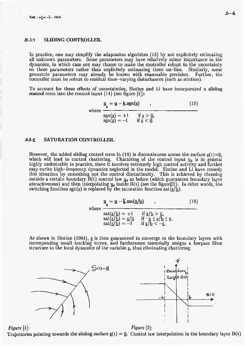
B.3R SLIDING CONTROLLER.
\ fb > I
I i
I
In practice, one may simplify the adaptation algorithm (15) by not explicitely estimating all unknown parameters. Some parameters may have relatively minor importance in the dynamics, in which case one may choose to make the controller robust to the uncertainty on these parameters rather than explicitely estimating them on-line. Similarly, some geometric parameters may already be known with reasonable precision. Further, the controller must be robust to residual time-varying disturbances (such as stiction).
To account for these effects of uncertainties, Slotine and Li have incorporated a sliding control term into the control input (14) (see figure [i]):
- u = g -k.sgn(f3) , (19) 6
where if g > 0,
0.3.2 SATURATION CONTROLLER.
However, the added slidin control term in (19) is discontinuous across the surface g(t)=Q, which will lead to contro f chattering. Chattering of the control input us is in highly undesirable in practice, since it involves extremely high control activity and urther may excite high-frequency dynamics neglected in the model. Slotine and Li have remedy this situation by smoothing out the control discontinuit . This is achieved by choosing
generai outside a certain boundary B(t) control law us as before Ghich
switching function sgn(s) is replaced % y the saturation
boundary layer attractiveness) and then interpolatin inside B(t) (see the words, the
As shown in Slotine (1984), s is then guaranteed to converge to the boundary layers with corresponding small tracking errors, and furthermore essentially assigns a lowpass filter structure to the local dynamics of the variable s, thus eliminating chattering.
Figure [i]: Figure [a]: Trajectories pointing towards the sliding surface s(t) = 0. Control law interpolation in the boundary layer B(t)

SlU
-1 '* 'I '1 , t v < 1 'I u I I-
*--- ,.-. -.. W
-.
1 ri -SPy-PA(Ä'B)3+ P"B)Jq = n
I:::::::::, IV
'I-
<*
re
I
SI
v , \ *..*O '[OO1=AW=dxl '4-

& W ..............
.... i::-.-*
-+ w ...............

r n
I I 1.
IS
1.
03
n
a1
4.
-1.1
L
u :: :: :: . I I . I .
2
IS
1.
4.1
a
Q
-5.
i i i i i i i i i i n i i n i m Is) -]O,
m cz) iri (1) 41.
............... A4 -s
............... .m. . . . . . . .
1. a. a 4 S. L 7. 1. t. In
e
' 5
Q 1. 2. 1. 4 a L 7. L 9. 10.
n m
e4 - aB
......... O1 I! ,...---* ..*- ....
........... .................
M .-.ZE ...............
Fzgure [13]: Saturation control + PD feedback + ad. coMP. for* [ K ~ = ~ o o ]

Pu BI '6 'i 1 % V t Z 'I 1 i:::: .....
............... + w
............... + w vi -0 .?=
't
'O1
'21 I 01.
ji - f- ............... w
w .I ,-:* t
'T ............... r
+- -.-,------ (2) ?Y m v ............................................ -3
1

VI 1 'I '1 V 'C mu I t 'I 'I 'O
t::::. .... .wU
VI 'b V x V '6 I 1 7 'I V b::::-.
% w ...............
. 'o01
I. 'rn
c '3
I WU 'O1 'b V '1 'I F I '< 'I '1 D t::.-... .. z-
............... (7) Y v7-F- -
* ...............
WU
'r
V
'I
9
9
1
'01
'I1
I Oir 17
IDIU
i::: '1 9 '5 I t 'I 'I 'O O1 'b 'I
...... r1-
'1-
co-
o
FO
I
Fl
I

aWU
VI '6 '8 .1 '9 'C I 'C 7 'I
*:::::z...
............... j=- )Y
WU
'O1 '6 '8 'L '9 S I .C 7 'I .O
#::::c..-. t 'I-
1 80
VI '6 8 'L 9 'C BWU I i 7 'I 'O
I-::::::... t
IV
01 '6 'I 'L 9 F BWU I T z '1 o
I : : : : : : ... .cl,.
........... 'I-
(21 4? * CV-
r- WL
BI * 'b V '8 V 'C '2 7
...............
(c-10 ............. hl
(wy ...............
WU
VI 6 8 '1 V .C * 1 '2 '1 8 a::::: ;... CU
.................
* rt
.r.
ZL- B

Jfi w
...............
PIIU UI 'I .L V T T 'S Z 'I 'O I::::: ....
IYU UI 6 I L 9 3 't s 7, I o e::::; .... 'I'
WU UI U 'D 'I '9 'C 'I 1 'I 'I 'e *:!::E'... 'P-
5 W
...............
Y t 'I1
BYU 'O1 .6 3 '1 9 1 'I 7 'I 'O
i : : : : : ....
MU 01 6 I L v T T I t I e 1:::: t.... f 10-
....................... ...........
bo
I
- 11
B)IU 01'6 I L * C T.1 1.1
e::::--. .. Cl.
'I-
CO
U
L-o
I
FI
......

tue-wfw-il-1990
C CONTROL OF A FLEXIBLE MANIPULATOR.
Gl
C. i INTRODUCTION.
In the control of robots, besides PID also advanced control techniques as computed torque control and adaptive control have been investigated. However, these control methods appear to be in their origin version only applicable to rigid manipulators. There is needed now an extension for controlling robots with elastic ioints and/or flexible links, while the problem of achieving stability is severe.
C. 2 RIGID MANIPULATOR CONTROL.
Industrial robots will be of great importance in future. Robots of today are used already for various purposes in different industries. Until now, the control of industrial robots has been studied extensively under the assumption that the (actuator) joints are stiff and that the links can be modelled as rigid bodies. This assumption can be justified for most of today's robots, because of their very heavv construction in order to avoid undesirable positioning inaccuracies that may be caused by elastic deformations and vibrations. The advantage of such stiff constructions is that (angular) encoders at the actuator joints (sonamed 'collocated sensors') can be used to get information about the actual position of the end-effector in space in a purely geometric manner. Therefore, the controller can use this information directly to perform the actuator inputs. The joints are then driven simultaneously, often by a simple PID servo loop. However, the main disadvantage of today's typical stiff robots is that they do relatively slow response.
C.3 FLEXIBLE MANIPULATOR CONTROL.
For higher operating speeds, industrial robots in future shall be made lightweight to reduce the driving torque requirements and to enable the robot arm to respond faster. However, as a consequence of this development, high speed operation leads to high inertial
and thus to less end-noint, ~ositionine: accuracv= This makes it, necessary to tuke Int^ consideration the dynamic effects of -joint elasticity and (distributed) link flexibility during rapid arm movements by more advanced control algorithms. Therefore, the feedback control system will be equipped with additional sensors giving information about the elastic vibrations to be suppressed or stabilized. Mostly, the control action will then still be carried out by the existing joint actuators (i.e., no additional actuators are used).
The inclusion of the flexible motion in the control action enables to achieve better positioning accuracy with the existing joint actuators. However, theoretically any flexible system has an infinity number of elastic modes, while the limited number of sensors and actuators restricts the controller design to a few critical modes. Therefore, mostly the mathematical robot model will consider only the first eigenmodes of each flexible link (in these papers too).
ferces which in turn cause CGnsiderabk e!astlc d&rmations of the maEipd&tûï members

tue-wfw-il-1990 G 2
C. 3.1 ComDuted toraue control.
A well known approach to improve the control of robotic manipulators is the comDuted toraue! inverse dynamics control method. Here, the control law is designed explicitely on the basis of a detailed nonlinear model, in order to compensate the robot nonlinearties and to guarantee a desired closed-loop behavior.
It is well known that the dynamic equations of a ri&J robot system may be globally linearized and decoupled by nonlinear feedback. This computed torque control approach transforms the equations of motion of the rigid system into a set of double integrator equations which can then be controlled b adding an 'outer loop' (PID-) control (pole-placement techniques; see for example b]) However, the dynamic model of a flexible maniphator is not feedback linearizable in the conventional way as for a rigid robot.
*) The 'rigid' computed torque control technique can be understood as a special case of a more general procedure for transforming a nonlinear system into a linear system, which is known as extemal/ feedback Eneaxizatiopz (121) a d leads to on of the possible approaches in controlling elastic robots (see also references [ 3 ] , [4], [ 5 ] ,
- The remarkable result obtained with pole-placement control of a feedback linearized system is that the closed-loop system has a desired behavior in the whole state space.
- However, the feedback linearization technique appears to be comput ationally expensive in general and requires accurate modeling and full state measurements.
161 and [71)
*) A second alternative mentioned in literature for flexible robot control is found in utilizing the concept of inte al manifold to the equivalent s i n d a r Derturbation model of the flexible rob- been shown that the reduced flexible system obtained then is indeed feedback linearizable.
A short review is given in chapter E: 'Two-time scale sliding control of a flexible manipulator - Slotine and Hong'.
c. 3.2 AdaD t ive control.
The use of a computed torque control model requires accurate knowledge of the physical manipulator parameters and its payload or is only meaningful if it is possible to identifv the model Darameters with satisfactory accuracy. This, because instability of the control algorithm will occur in case of parametric uncertainty. With off-line identification strategies there will always remain the question wether the obtained estimated parameter values are validate for a variety of different desired trajectories or just for one.
on-line, because then they can be adjusted at any time for each arbitrary reference trajectory and never need to converge to certain constant values.
An adaDtive control approach seems to be of great relevance for the control of systems with unknown or timevarying Parameters or even with an unknown part of dynamics. A possible way to handle with parametric uncertainties is to implement an adaptive computed torque control law as follows:
otb~ïwise, one WoUld pïefeï ie, identify the mudel ya,ïam1eters fûr cuntroi purposes
- first adopt a suitable (linearization of the) robot model, - then perform on-line estimation of the model parameters, - finally apply the computed torque control law with the adjusted parameters.
The adaptive algorithms may for example be derived from Lyapunov global stability considerations or from the Hyperstability theory of Popov [9].

tue-wfw-il-1990 G-3
c. 3.3 Sliding control.
Finally, it will be necessary to assure robustness to the effects of uncertainties of those model parameters not estimated on-line, unmodelled dynamics and disturbances, for
Slotine and Li
occurs), one must care about the admissable inputs to the s stem and probably has to use the boundary layer approach of Asada and Slotine [11[(which gives, however, less tracking accuracy: see chapter B: 'On the adaptive control of robot manipulators - Slotine and Li'). Because the physical constraints on the available motor power limit the extension of the actuator inputs, for practical implementation it would perhaps be possible in some way to use the generalization approach of the computed torque control strategy as has been presented by Heeren 101 (see a short desription of it in chapter D
example by incorporating a sliding control term into the control input [lo]). However, since sliding contÏ-ol gives rise to discontinuous signals i.e., chattering
'Generalized computed torque control of a A exible manipulator')
References: Kokotovic, P.V. (1985).
Recent trends in feedback design: an overview. Automatica, Vol. 21, No. 3, p p 225-236, 1985.
Nijmeijer, H. and Van der Schaft, A.J. Nonlinear dynamical control systems. Springer- Verlag, New- York, 1990.
(1990).
Cesareo, G. and Marino, R. (1984). On the controllability properties of elastic robots. 6th Int. Conj on Analysis and Optimization of Systems, INRIA, Nice, 1984.
Robust stabilization for a class of nonlinear systems. Proc. 7th Int. Symp. on the Math. Theory of Network and Systems, (MTNS) Stockholm, Springer- Verlag, june 1985.
Journal of Dynamic Systems, Measurement and Control, Vol. 109, p p 310-319, 1987.
Robust nonlinear control of robot manipulators. Proc. 24th IEEE Conj on Decision and Control, F o r t Lauderdale, p p 1767-1 772, dec 1985.
Feedback linearization of a flexible manipulator near its rigid body manifold. Systems and Control Letters, Vol, 6, p p 187-192, i985.
Two-time scale sliding control of manipulators with flexible joints. American Control Conference, BSE DPC 82 AME.
Spong, M.W. (1985)
(1987)' Modeling and control of elastic joint robots.
Spong, M.W. and Vidyasagax, M. (1985).
Khorasani, K. and Kokotovic, P.V. (1985).
Sioiine, J.4- E. and Hong, S. (i987)
Popov, V.M. Hyperstability of control system. New York, Springer- Verlag.
(1969)
Slotine, J.-J. E. and Li, W. (1987) On the adaptive control of robot manipulators. Proc. ASME Winter Annual Meeting.
Robot analysis and control. John Wiley & Sons.
Asada, H. and Slotine, J . 4 E. (1986)

tue-wfw-i1 P -1
Jo GENERALIZED COMPUTED TORQUE CONTROL OF A FLEXIBLE MANIPULATOR.
MANIPULATOR DYNAMICS.
It has been shown that a fairly general model for a manipulator has a nonlinear structure of the following kind: r
where (1)
is the [nxl] vector of independent degrees of freedom of the manipulator model, is the [mxí] vector of actuator inputs.
D. 2.1 MANIPULATOR CONTROL.
The main control objective is usually to make the manipulator's end-effector follow some desired path in space. Frequently, it follows from the manipulator design that the number k of output quantities y(t) is equal to the number m of servomotor input variables g(t). y(t) Determines the end-effector position and orientation and depends on d t ) :
(2)
If the desired path for y is specified by a known, time dependent function Ed(t), then the main objective is to let the tracking error E(t)-Yd(t) tend to zero. A more complete formulation may also include desires about the derivative of y(t).
p.2.2 COMPUTED TORQUE CONTROL.
Often, the computed torque control law for a manipulator is chosen as follows:
where is the [nxl] vector of generalized coordinates due to the desired trajectory,
e = q - q d'
is the [nxl] tracking error: -
However, if a flexible link manipulator has to be controlled, C&(t) cannot be determined explicitely from equation (2), because n > k. Therefore, if we still decide to use control law (3), this is only possible when assumptions have been made about the behavior of [n-k] variables of c&(t) (for example, that the flexible state variables and their derivatives have to remain zero). This does not indicate that this is an optimal choice (see for more about the reference trajectory: W. Winkelmolen [1987]).
tue-wfw-i1 D-2
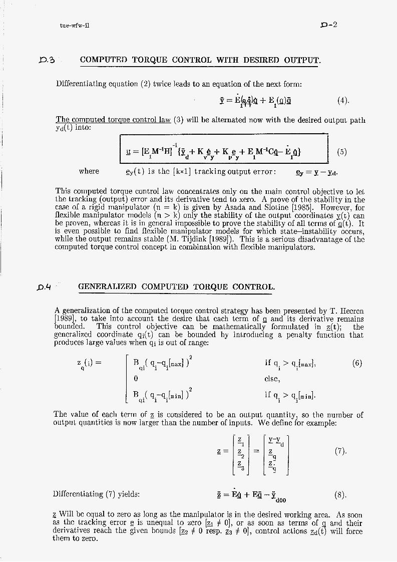
D. 3 COMPUTED TORQUE CONTROL WITH DESIRED OUTPUT.
Differentiating equation (2) twice leads to an equation of the next form:
The commted torarie control law (3) will be alternated now with the desired output path Yd(t) into:
-1 U = [E M-lH] {y + K e + K + E M-lCQ- E 9)
a d V Y P Y 1 1 - (5)
where - ey(t) i s the [kxl] tracking output error: ey = y -Yd.
This computed torque control law concentrates only on the main control objective to let A prove of the stability in the
by Asada and Slotine [1985]. However, for stability of the output coordinates y(t) can
be proven, whereas it is in general impossible to prove the stability of all terms of q(t). It is even possible to find flexible manipulator models for which state-instability occurs, while the output remains stable (M. Tijdink [1989]). This is a serious disadvantage of the computed torque control concept in combination with flexible manipulators.
the tracking (output) error and its case of a rigid manipulator (n = flexible manipulator models (n >
tend to xero.
P.4 GENERALIZED COMPUTED TORQUE CONTROL.
A generalization of the computed torque control strategy has been presented by T. Heeren [1989], to take into account the desire that each term of g and its derivative remains bounded. the generalized coordinate qi(t) can be bounded by introducing a penalty function that produces large values when qi is out of range:
This control objective can be mathematically formulated in Z(t);
z (i) = 9
if q. > q.[maxI,
else,
if q. > q.[min].
1 1
1 1
The value of each term of 3 is considered to be an output quantity, so the number of eiitput yiimtitiev is XIOW larger thar, the r,~mber 3f icputs. We define fûr e;ami;!e:
Differentiating (7) yields:
- z Will be equal to zero as long as the manipulator is in the desired working area. As soon as the tracking error e is unequal to zero [ZI # O], or as soon as terms of g and their derivatives reach the given bounds [EZ # O resp. 23 # O], control actions zd(t) will force them to zero.

tue-wfw-i1
- K ê + K e - V-Y P Y
z = K z -a b -4
K z: bd- q - - -
D-3
In this way it is obvious that we want to obtain:
1
where Sd(t) can be chosen as:
Consider the main control objective: Combinating this with equations (1) anL (4) w
Unfortunately, it is in general impossible to choose u such that equality (10) holds, because the dimension of is larger than the dimension of u. Hence, all that can be done is to minimize some norm of & Because there is further the desire to keep the force/torque inputs u(t) bounded too, the minimization of d may be combined with the minimization of u. This can be realized by minimizing a scalar function J, which is a kind of respone quality functional and uses positive weighting matrices W and R in order to denote the relative importance of each objective:
A minimum of J with respect to u can be found by requiring that the derivative of J with respect to u is equal to zero. This results in the following generalized computed toraue control law:
P. 5
where Z = EM-lH.
COMPUTED TORQUE WITH SLIDING CONTROL.
In this section, the computed torque control law (5) will be described through the sliding control approach of Slotine and Li 619861.
A switching surface, which zeros the tracking error and its derivative, is defined as:
( i3j . (" -, =ey-A3=0
The time derivative of the switching surface along a trajectory of the system can be expressed as:
- s = E y - h e y = 1 3 - yd - hey =
= E l Q + E l Q - ? d - A e y =
= E14 + E1M Hu - E1M CQ - Ed - Aey -1 -1

tue-wfw-i1 D - 4
The eauivalent inmt to the svstem when it is in sliding mode is:
u = [E M"H]-'{ + AC + E M-lCp - E p } I d Y 1 1 -
eq
which [with (13)] means that both e(t) and e(t) asymptotically tend to zero when the system is in sliding mode; i.e., the sliding mode guarantees total stability of the system.
It is the objective that the trajectories of the system beginning from any initial condition are attracted towards the switching surface s(t)=Q in a finite time and thereafter maintain in sliding mode. The control law satisfying the reaching condition
( 1 7 h
may have many forms and can for example be chosen as follows:
Substituting this Q in equation (14) yields: -1
- S = EIM% [EIM-IH] { y d + Ae, + ElM-'CQ - E1Q - k sgn(s) }
This satisfies the reaching condition (17) and thus guarantees that the system will reach the sliding surface in finite time. Then, during sliding mode, the system is insensitive to parameter uncertainties and disturbances.
To decrease the chattering of the input signal, Slotine and Li propose utilizing the boundary layer approach of Asada and Slotine [1985], in which the switching function is replaced by a saturation function:
J
-1
In literature, sometimes the switching function is embedded in the robust controller design of a stabilizer fm parametric coeertsinties, disturba~ces and damping of elastic oscillations: GFJ-; *
= u - [EIM-'H] y - PBpf eq
where * means that the value of the function with * is not necessarily equal to the actual value, gf represents the flexible motion of the robot
- v is a new input to the system (this last term in (21) is here not considered further),
(some indications how to define it are given now).

tue-wfw-i1 D-5
Substituting equation (21) without its last term into (14) gives: A -1
- S = ElM-lH { ueq- [ElM-lH] 1 } +
where
Each element of M(q) and C(g,Q) is assumed to have its upper and lower bound, while the desired trajectory Ed is assumed bounded too (because otherwise the trajectory cannot be realized by finite input torques/forces to the system) and y has its bounds due to the actuator saturations. Thus, each element of above equation is bounded and one of the stabilizer control inputs, which satisfy the reaching condition (17), is given as follows (Kosuge and Furuta [lSSS]):
where
when Qjsi > O, when Qjsi < O, when $jSi > O, when 9 j S i < O,
In equation (23) the second term could be chosen zero. But in practice, this term can be used in order to decrease ksi. Large ksi causes a large chattering of vi.
Equation (23) guarantees that the sufficient reaching condition (17) for the sliding mode to occur is satisfied, as long as V i does not exceed its physical limit due to the actuator saturations. This means that vi does not satisfy the Sufficient condition if M is extremely far from its actual value M and thus W i becomes very large. But this is not the case in practice, when the parameter uncertainties and variations caused by a payload is not considered so large in usual robot arms. There is the question in which way this stabilizing approach can improve adaptive control of flexible manipulators.

tue-wfw-i1 D-
COMPUTED TORQUE CONTROL WITH A FULL REFERENCE TRAJECTORY.
The flexible manipulator dvnamics has the next form:
where is the [nxl] vector of independent degrees of freedom of the manipulator model, is the [mxl] vector of actuator inputs (m < n),
The known [mxl]desired trajectorv vector is: Y,@)= Y[ 9Jt) 1 (n unknown variables qri and only rn equations ydi=y(qri)).
*) Off-line, a [nxl] reference trajectory vector qr(t) will be determined with the m equations(24) and the next (n-m) equations of flexible manipulator dynamics (1):
where o a h = [ O [(n-m)xm] I [(n-m)x(n-m)] 1 .
*) Which remains from (1) will on-line be used in the form of the following computed toraue control law:
where

tue-wfw-i1 D- 7
D.6-2 Example: THE TR-ROBOT WITH ONE FLEXIBLE LINK
(only first eigenmode modeled).
The [3x1] vector of independent degrees of freedom:
I translation of the carr i age rotation of the pendulum bending of the el a t i c p e ndulum
The known [2x1] desired trajectory (2) is:
x + Icos(cg j-w sin(p j lsin(cp )+wecs(<p )
r r
r
The [3x1] reference trajectory qr(t) and its derivatives to be determined:
= yd/sin( pr) - 1 -> (7)
Here, equation (3) from maniDulator dvnamics (1) can be described as:
By substituting (7) and (8) into (9), one obtains an equation with which pr and its derivatives can be determined:
f( pr,@r,Pr) = g(xd$d$d, yd,yd,yd) (10)-
(To facilitate the solution of (10) one can assume for example that <pf
is a second-order polynome: pr(t) = a + bt + ct2 , @r(t) = b + 2ct , pr(t) = 2~ .)
Lue-wl w - I 1
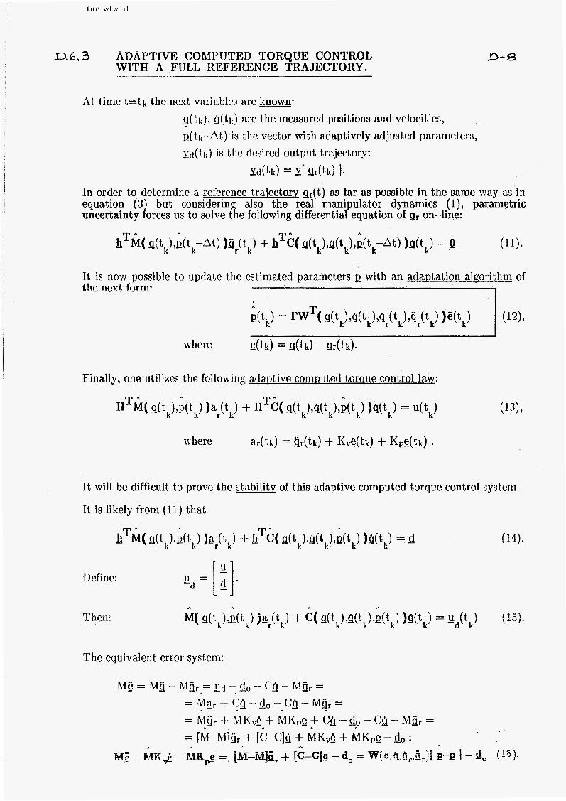
D.6.3 ADAPTIVE COMPUTED TORQUE CONTROL WITH A FULL IXEFERENCE TRAJECTORY.
D-€3
At time t=tk the next varia,bles are known: q(tk), G(tk) are the measured positions and velocities, Q(tk-At) is the vector with adaptively adjusted parameters, Yd(tk) is the desired output trajectory:
Yd(tk) = Y[ qr(tk) 1. In order to determine a reference traiectorv gr(t) as far as possible in the same way as in equation (3) but considering also the real manipulator dynamics (i), parametric uncertainty forces 11s to solve the following differential equation of gr on-line:
(11). l! T A M( dtk),E(tk-At) )4r(tk) + 0 T - C( s(t,)?Q(t,),Q(t,-at> )4(tk) = 0
It is now possible to update the estimated parameters Q with an adwtation algorithm of the next form:
d t k ) = rw ( s(t,)?Q(tk)?Q (t,),sr(t,) )e(t,) (1%
where - e(tk) = q(tk) -g r ( tk ) .
Finally, one utilizes the following adaDtive computed toraue control law:
It will be difficult to prove the stability of this adaptive computed torque control system.
It is likely from (11) that
(14). 0 T - M( 9(tk)'a(tk) l apk) + J! T C( - q(tk)>Q(tk)?B(tk) )4(tk) = d
Define :
m I hen:
-d u = [i].
The equivalent error system:

tue-wfw-i1 E- 1
TWO-TIME SCALE SLIDING CONTROL IE OF A FLEXIBLE MANIPULATOR.
Slotine, J.-J. E. arad Hong, S.
INTRODUCTION.
[1986]
The main idea of the ap manipulators leads to a two It starts with a separation
in those describing the rigid body motion resp. those describing the flexible effects:
Then, they investigate the elasticity properties by the sinnular Derturbation technique of Marino and Nicosia [1984] to decompose the manipulator-dynamics into a 'u' resp. a 'u' submodel: (417
(51,
Assuming that only small deviations from the rigid body motion will occur and are to be considered, they further use the concept of slow manifold (Khorasani and Spong [1985]) to obtain the next linearized singular perturbation model:
The reduced flexible model (6) represents the system dynamics restricted to a sonamed 'slow manifold' described by:
(a and is of the same dimension as the rigid model of the flexible system, but preserves and captures the dynamics of the full system to a higher degree of accuracy. It can now be used to design a slow feedback control Zr. Further, a fast control Gf is needed in order to guarantee that the slow manifold is actually attractive, i.e. that all system trajectories converge to the manifold. The composite two-time scale controller is then defined as:
= L&,k,z,&p), ur(x>k,P) controls the rigid body motions, uf(g-b(x,$,Ur,p), &h(x,k,ur,/i)) controls the elastic modes.
For the required robustness to parametric uncertainty, Slotine and Hong finally use the sliding control methodology of Slotine 1119841 to design the two-time scale sliding controller:
&=us + u (10). r -%
*)
*)
Based on the control Gr for the rigid robot system, the slow sliding controller usr is designed to account for parametric uncertainty on the slow manifold. The purpose of the fast sliding controller gsf is then to force the fast variables to follow the slow manifold, despite the presence of uncertainty.

tue-wfw-i1 E-2
L 2 MANIPULATOR DYNAMICS IN SINGULAR PERTURBATION FORMULATION.
In the paper of Benati and Morro [1988], a chain of flexible links has been modeled as a system with a finite number of degrees of freedom. The main advantage of their approach through Lagrange’s formalism is, that it leads to explicit dvnamic eauations of the flexible manipulator (in terms of well defined geometrical parameters) which, in general, can be written in the next form:
is the mxl] vector of actuator inputs, is the t 11x11 vector of generalized coordinates which can be split up into two vectors:
where
g =
motion of links, degrees of freedom.
3 rgi,+) can be splif up inik : n(rt;+j = ga +)+ E,h+qg
With Q = M-l[ HU-Q ] and after some mathematical manipulations, we get:
Defining: x = slr z = kg
f -
P =
the equations of motion for the flexible manipulator can be written in the general form of
x = il,(x,k,PWa -p A,(X,& + B,(X,PE)U (W1 I
where is the kxl] state vector associated with the ‘slow’ dynamics, is the t (n-k)xl] state vector associated with the ‘fast’ dynamics, is the inverse of the joint/link mechanical stiffness [very small scalar].
x ru Z -
By formally setting p=O and eliminating from the equations, (12)-(13) are reduced to the equations of motion of a rigid manipulator: M(X)X + n(x7.t) = HU.

tue-wfw-i1 E-3
E03 DESIGN OF THE SLOW SLIDING CONTROLLER
The singular perturbation model (12)- nd is not directly linearizable. However, it can easily be 'fast' submodel by using the slow manifold:
(8)-
which can be obtained as the solution of a partial differential equation formed by substituting its expression into equation (13):
Once h is determined from this sonamed manifold condition, the dynamics of the system 12)-(13) on the manifold are given by a reduced-order system referred to as the reduced 6 exible svstem, which is performed by replacing by h in equation (12):
The computation of the slow feedback control out of this reduced flexible system is complicated by the need to solve the manifold condition (14). Therefore, an approximation to h and ur is obtained by expanding them in a power series of ,u. In practice, the followl capture the dynamic effects of interest:
(16)7
where - w is a new input which is assumed to be known, - ho and go are the manifold resp. the control
obtained from the rigid model @=O):
(14) a20+A20ho+~20Uo = Q -> O0 = -A20-1[i120 + B203!0] (m (15) aio+Aloho+~lo~o = E -> - uo = -B-'[a - IV] (1917
where = [B10-A10A2ö1 B201, - 8 = [a10-A10A2ö1 3201.
Using this known rigid manifold ho and control go, we can obtain hl from (14) under the assumption that the fast variables are on the first-order corrected slow manifold [neglecting terms of order p2]:
will lead to an expression for hl: where
h = A -l[d - B E ] -1 20 20 1
expressions with l / p are omitted, d=li,-A&%-AAh - A B u -B U
2-9 2- 25-8' -

tu e-wfw-i1 E- 4
Also, the first-order corrected slow subsvstem can be written [p2=0]:
where
*) When there is no model uncertainty: 2 = &o+ Aloho+ Biouo= w. Then the corrective control compensating for flexibility will be:
(24). U = -B- [ b + c ] -. - *) However, with Darametric uncertainty, ho and go are only known as:
h = --A -1[ a +B u ] -0 20 -20 20-0
A - a
u = -B-l[a -E] -0
where * indicates available estimates.
Therefore, an additional control term is required in the corrective control ui7 in order for a flexible manipulator to track the desired trajectory despite the presence of parametric uncertainty. Considering equation (23), Slotine and Hong have derived the following slow sliding control law:
where ux Is a new input designed to achieve desired closed-loop specifica,tions:
- u = 2 -K, e -Kp -Ks sat[ s /i 3 , x d x x x x X x x
- e, is the tracking error of the rigid motion state variables:
- sx is the slow sliding surface defined as:
Ks and sat[ / g ] are defined as in Asada and Slotine [1986]. X x x
Finally, the slow slidincr controller Usr is in its first-order expansion defined in the same way as Gr in (17)
Thus:
* .. L . L .
u s = U +pus = B - l { - a + w + ~ - w - , ~ [ b + c ] } r -0 1 X

tue-wfw-i1 E-5
E*4 DESIGN OF THE FAST SLIDING CONTROLLER
The slow submodel was derived under the assumption that the fast variables z follow the slow manifold h. However, this is not necessarily guaranteed in the presence of parametric uncertainty. Therefore, a fast control uf is needed to force the fast variables to follow the desired manifold, i.e. to make the desired manifold attractive despite par amet ric uncertainty:
where TJ represents the deviation of the fast variables from the desired manifold:
- - ( h0+ph1 )
The influence of the fast control on the slow subsystem can be neglected in the design when TJ is maintained at a small valiae by the fast sliding control II~ after the decay of fast dynamics. To derive the fast submodel, we can make the assumption that the slow states x and their derivatives are fixed parameters xo and go during this fast transient. This allows to simplify the problem when the slow and fast time scale are significantly different: tf < tr. By expressing the fast flexible model (13) in the fast time scale defined as tf = t /p , we get:
- z' = 2 (St/&) = pa,
- z" = - Z(St/Stf) = p2&.
where indicates differentiation with respect to tf.
The first-order corrected fast manifold can be defined from the equation above:
Which remains from (32) is the following expression:
22" = p&(Xo7!!0,p373') + pA2(X0,p3)8 + pB2(xO,p3)uf
Neglecting terms of order ,u2, we obtain the first-order corrected fast submodel:
19 - rl - ~2n(xoi~olQ711+) + PA 2n (x o 70)g + m 2n (x o - $)af
(34).
(35).

'X3TIOXLNO3 3NI(II?S 3W3S 3MIA-OML 3HL 'C *3

F-1 tue-wfw-il-1990
F (ADAPTIVE) TWO-SUBMODEL BASED COMPUTED TORQUE CONTROL OF FLEXIBLE ROBOT SYSTEMS.
F. 1 INTRODUCTION.
The problem in controlling a lightweight mechanical manipulator is to perform fast, accurate and robust motions despite structural flexibilities, payload variations and other environmental disturbances. An (adaptive) twosubmodel based control approach has been developed to extend the familiar computed torque control scheme for rigid robot systems to flcxible robots.
F. i. 1 The flexible manipulator system.
A lightweight manipulator may have flexibility in the link structure and/or elasticity in the motor joints. For most manipulators, joint elasticity has a greater significance for control system design than the actual bending modes of the links. Furthermore, the distributed link flexibility can be approximately modeled by a chain of rigid sublinks interconnected by elastic joints. Hence, a more accurate (thus higher order) representation of robot dynamics involving elastic joints should be taken into account to get better control performance.
In comparison with a rigid robot, the system dynamics of a flexible robot with n degrees of freedom is still governed by the same type of second-order, couded, highly nonlinear different ia1 eauat ions: I M(q)Q + o(s,Q,t) = Ha 7 (1)
where q(t) is the vector with n generalized coordinates, M(q) is the [n*n] mass inertia matrix, - u(t) is the vector with m motor input signals, - n(q,q,t) contains the centrifugal and Coriolis forces/
T X 7 : t L r T AT IT lllfi nk+a<- On ~ v o + n v A n v nnnl;nnnv A:ggnvnm+;o1 V V l b l l y = 9 y j w c W U b a J l l A l l 1113b--U1UCl L I u l l l l l l G c z l u l l l G ~ G l l t J l a d
torques, yravi t y, friction, etcetera.
equations:
However, an important difference is that, when the structural flexibilities are included, the number of inputs is less than the number of denees of freedom (m<n). A 'rigid' control strategy ur(t), which just tries to track a desired trajectory in space specified by m generalized coordinates, will often result in an instable system behavior. Therefore, the control system must deal with control of the elastic vibrations as well as the joint trajectory tracking. However, it is not possible to find a control input for a lightweight manipulator which will accomplish perfect tracking of any given desired trajectory in joint space while totally damping the undesired flexible deflections. It is more realistic to search for a control law achieving both a reasonable trajectory tracking and a certain stabilization of accept able vi brat ions.

tue-wfw-il-1990 F-2
F.I.2 Two submodels of the flexible manbdator svstem.
In first instance, starting with Slotine & Hong [1987], we assume that n=2m and that the dynamic model (2) of the flexible manipulator can be split up into
24 = g(x,z,t) 9 - 2 = Mx,z,u,t) -
If the desired trajectory is specified by xd(t) , the tracking error is defined as:
Then, we introduce a reference manifold error: ez = zr -z >
in which the reference vector .Z,t) must be chosen in such a way that substitution of (6) in (3) will result in a stable differential tracking error equation:
- e = &j -g = &j -g(z,g,,t) . (7)
That is to say: the tracking error g(t) will tend to zero in time if gZ=Q.
F.1.3 Two-submodel based (adaDtive) flexible robot control.
To force the generalized coordinates Z(t) to their references zr(t), the intention now is to obtain a stable differential reference manifold error equation too:
by choosing a suitable 'flexible' control input signal &c,z,t), which will be composed of a computed torque control part (with internal PD action) and, for example, a sliding control part (in order to obtain robustness against uncertainties and parameter variations: Asada & Slotine
and of a computed torque control term multiplicated with the inverse of the stiffness matrix K of all elastic joints and/or flexible links:
. The computed torque control part appears to be a combination torque control law ur(t) of the robot model without fiexibilities of the 'rigid'
The term with ue tries to force the flexilbie motions to behave in a mere natiiral way according to the equations of motion of the flexible svstem.
Unfortunately, the computed torque control method relies heavily on an accurate prior knowledge of the robot system dynamics and, therefore, above approach will further be expanded to an adaptive control technique in which the unknown, but constant system parameters will be adjusted on-line (basically according to the method of Slotine & Li [1987]). Finally, the global asymptotic stability of the control system is guaranteed through the Hyperstability approach of Popov [1969]. The new (adaptive) flexible robot control method will be illustrated by simulation results.

tue-wfw-il-1990 F-3
F.2 THE FLEXIBLE MANIPULATOR SYSTEM.
The equations of motion for a manipulator system with linear elastic ioints are:
vector with link variables, vector with actuator variables,
where
inertia matrix of the rigid-link robot, J is the mass inertia matrix of the joint motors, K is the diagonal stiffness matrix of the linear elastic joints.
(12)
(13).
he eiastic forces/torques at the joints, coupling equation (1 O) with (1 1) :
MQ r r +CQ r + $ = g = ~ ~ - J t j f -BQ f
The equations of motion for the rigid maniwlator svstem are:
According to Slotine and Hong
r x = q
3 = K(ilf-!Q p = K-'
19871, with the definition of
as the 'rigid' variables, (15)
as the 'flexible' variables, (16)
as the very small 'parasitic' elasticity matrix, (17)
the equations of motion of the flexible system (10)-(11) are changed into those of a socalled singularlv Derturbated svstem:
If p->O, equations (18)-(19) become the equations of a quasi-steady state system:
which approximates the rigid manipulator model (14) and represents the relationship between the rigid state variables x(t) describing the behavior of the flexible system (10)-(11) if it is forced to constrain its 'flexible' evolution of z(t) on the reference manifold zr( t ).

tue-wfw-il-i990 F-4
F.3 RIGID COMPUTED TORQUE CONTROL.
The first step in the derivation of the two-submodel based control law is the formulation
where - e =e+K Je is a reference trajectory error r X
e = x - is the tracking error. -d
With this control input we can define a certain 'reference manifold', describing the elastic forces/ torques required for manipulating the rigid links along the desired trajectory:
- z = M (z)(Z +K e ) + C(x,&)& +g(z) r r r r r
The equivalent reference trajectory error equations of the closed-loop system are:
where
M (E +K e ) = Z (25) r r r r
- e = z -z is the reference manifold error (26) z r
F. 3.1 Slidine; control term.
If p is very small, i.e. if the elastic joints are nearly stiff, there is only needed an extra sliding control term gs(t) (to be added to Ur(t)) in order to force the flexible state variables z(t) towards the reference manifold zr(t) and to keep the system in sliding motion on e,(t)=o:
- l l=g + g r S
-- u,. represer,ts the 'cquivde~t' c m t r d term. (21) when the system is in sliding motion. A variable structure control (V.S.C.) law is obtained by Petting the control function u be defined as follows:
- U-
where a necessary and sufficient existence condition for the local existence of sliding motion on eZ=Q is:

tue-wfw-il-1990 F-5
As a result of this control policy, the flexible state trajectories of the system reach locally the sliding surface eZ=Q if:
i.e., in the neighbourhood of eZ=Q is the surface reachabilitv condition:
(31)
which guarantees a crossing of the sliding surface gZ=Q from each side of it by use of a sliding control term (for example: = -k.sgn(%); see Slotine & Li [1986]).
F.4 FLEXIBLE COMPUTED TORQUE CONTROL.
If the parasitic elasticity parameter p is not very small, also the 'flexible' terms in the equations of motion have to be compensated for in the computed torque control, instead of approximating only the rigid manipulator system with p=O.
Considering the flexible robot model (18)-(19), by substituting the elastic forces z(t) of (18) into (19) we get:
pJH + pBS + [M (g)+J]g + [C(x,&)+BJ& + g(x) = U r
The flexible computed torque control law will be
= U + /I{ J(Z +K e ) + Bg } (33) r z z
Now, the equivalent reference trajectory error , cq. reference manifold error equations are:
(34)
(35)
Finally, combination of (34) and (35) leads to the equivalent error equations of the total closed-loop system:
I [M +J](e +K e ) + @(E +K e ) = 0 r r r r z z z

(OP)
r n
1= s zz
1 ]= s
1 = zTs aiaqM

tue-wfw-il-I990
T V=-g &e 5 0 Y Y
F-7
(45)
F.5 STABILITY OF TRE OVERALL CONTROL SYSTEM.
In anticipation on an adaptive flexible control system, Lyapunov's stability approach shall be combined with the Hyperstability theory of Popov [1969] for generalisation.
Define a Lyapunov function candidate: where P is a positive definite matrix.
Difkrentktiting ef V(+\ \UI g ives:
Using error equations (41) leads to:
1 T' T IT T V = - g Pg + e PAg =-g {P+PA+A P } g . 2 Y Y Y Y 2 Y Y
(43)
(44)
For a more general approach in deriving a globally stable control law u(t), it is however better to use the HvDerstability theory of PODOV, which requires that:
1 ' T with finite y and where jy = -{ P+PA+A P }e . 2 Y
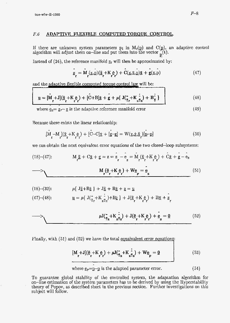
tue-wfw-il-1990 F-8
F. 6 ADAPTIVE FLEXIBLE COMPUTED TORQUE CONTROL.
If there are unknown system parameters pi in M&) and C(p algorithm will adjust them on-line and put them into the vector A 0).
E Instead of (24), the reference manifold gr will then be approximated by:
an adaptive control
A
where gz= zr- is the adaptive reference manifold error
Because there exists the linear relationship:
(48)
(49)
we can obtain the next equivalent error equations of the two closed-loop subsystems:
(1 8)-(47):
-’\
A ,. A , . A
M Z + C g + g = z = z - e = M ( Z + K e ) + C & + + - e z r r z r r r r
,. M ( % + K e ) + W e = e
r r r r -P z
(1 8)-( 32) :
(47)-(48) :
-’\
p{ Jg+B&}+ J z + B & + g = u
- U = p{ J ( Z +K e )+B& } + J(Z +K e ) + BZ + z A
r i r r - r z - z
A
pJ(- +K e ) + J(e +K e ) + = 0 e2 2-2 r r r Z
Finally, with (51) and (52) we have the total equaivalent error eauations:
I [M +J](% + K e ) +@(e +K e ) + WG = O r r r r -2 2-2 P (53)
where g,=~-p is the adapted parameter error. (54)
To guarantee global stability of the controlled system, the adaptation algorithm for on-line estimation of the system parameters has to be derived by using the Hyperstability theory of Popov, as described short in the previous section. Further investigations on this subject will follow.

tue-wfw-il-1990 F-9
F. 7.1 Conclusions.
The main problem in control of flexible robots, namely the number of control inputs being less than the number of controlled variables, has been faced by a composite control law consisting of the conventional 'rigid' computed torque controller and a 'flexible' computed torque part multiplicated with the inverse of the stiffness matrix. The resultant control system resembles the socalled 'two-time scale sliding control' technique of Slotine & Hon [1987], based on a singiilar perturbation formulation of the equations of motion and the concept of integral manifold. Fortunately, in this approach the stiffness of each elastic joint does not have to be relatively large neither is there the restriction of Slotine and Hong that there have to be as many elastic joints as motor inputs (no flexible links, no rigid motor joints). Both methods require all system state variables (positions and velocities) for feedback. But then, Lyapunov's stability theorem guarantees that the output trajectory will follow the desired trajectory and that the elastic forces/torques, which are not directly constrained by the output specifications, remain on a certain 'manifold', due to the natural flexibility behavior of the system. In the next chapter, the key concept will be illustrated with simulation results of a Translation-Rotation (TR-) robot with one elastic joint.
Iri first i~s t ame , the motion control of a manipulator with elastic joints based on precise knowledge of the system parameters is considered. Due to parameter uncertainties and/or variations, it is not possible in practice to exactly compensate the manipulator dynamics. Therefore, the earlier mentioned flexible computed torque control method is finally adapted in an adaptive flexible control algorithm, based on the 'rigid' adaptive technique of Slotine & Li 19871. Stability will be guaranteed by the Hyperstability approach of Popov [1969 f .
Future research.
While the extension of the computed torque control (CTC) technique to joint-level control of flexible manipulators seems to be quite straightforward, a more involved situation arises for the end-effector trajectory control. The number of outputs is taken equal to the number of available inputs, but if there are more ioints than actuators (especially in case of approximated link flexibility) the basic limitation is due to the noncollocation of actuators and controlled outputs. For this class of manipulators, the knowledge of the desired trajectory and of its time derivatives is not enough to determine the required forces/torques instantaneously. Instead, a dynamic inverse system has to be used on-line to generate the natural 'reference' behavior of all system state variables due to the desired output trajectory. To address this problem, future research in 1991 will be concentrated on the development of an output-traiectorv based version of the (adaptive) flexible CTC controller.
References: * Asada, H. and Slotine, J.-J. E.
Robot analysis and control.. (1986)
* Jûhn Wileg 8~ Sons.
Hyperstability of control system. Popov, V.M. (1 969)
* New York, Springer- Verlag.
Two-time scale sliding control of manipulators with flexible joints. Slotine, J.-J. E. and Hong, S. (1987)
* American Control Conference, BSE DPC 82 AME.
On the adaptive control of robot manipulators. Slotine, J.-J. E. and Li, W. (1987)

I

_._ ___^ . . .
. ..

I I
.. . ... . -

-rUE-WVW-OC 44- 4590 G - 3
/> i
i
. . . .
. _ .
. . .
. . . . . .
. . . . -. . . . .
. . - . - -.
........ - . . .
, - -.- -
..... ..
. . . . . --_ ..
_ _
. . . . - . . . . . .
. . . . . . .
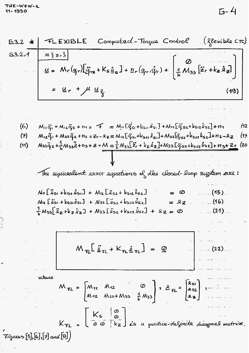
I 1 I I
. ..
I J
f
,..'
t7 -9

G-5
. . . . . . . . .
. . .......... -- ---I . . . . . . ........ .^_^_._ . . . . . . . . . . . . . . . . . . . . . . . .
.... .- .
... - - ........
--
....
. . “ ^
. .-.- .
. . . .
...... -
. . . . . . .- .. .-
. . . - -. -
. -.
.....
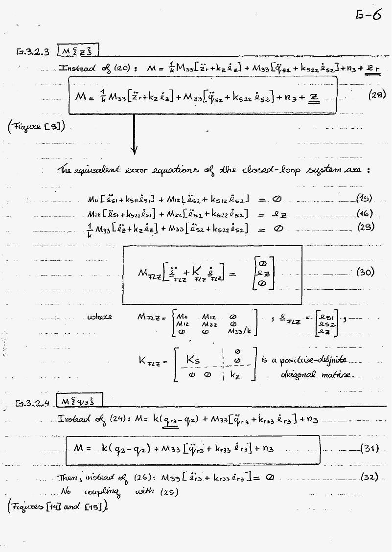
........ ._f. ...
..
. - .......
.. - ........
.- -- _- ...............

h.4 Control simulation results on the 3 D.O.F. elastic-joint TR-robot.
*)
*)
The initial system state variables ql(t0) and qZ(t0) are due to the desired trajectory at t=to: qid(t0) resp. qZd(t0). If nothing else is mentioned: Ks = diag[lO], k, = 10.
Figure [i]: Figure [2]:
Rigid Computed Torque Control (3):
Flexible Computed Torque Control ( 19) [ (1 2)-( 20)] :
Ks=O. - _ _ _ - _ _ _ K s = diag[lO].
Figure 1141; Figure 15 *
Flexible CTC (12)-(24), qr3 (23): Ks = diag[lO], Ks = O, k Z = 10. - - __ _ _ - __ - - -19 Ks = diag[lO],
Flexible CTC (12)-(31), qr3 (25):
Ks = diag[lO],
k, = 10.
k, = O.
Ks = O, k Z = O . _ _ I _ _ _ _ - - __ -16 k, = 10.
0.01 0.01 v
8 0.005 0.005 e a 2 O h o
8 -0.005 80.005
Y
%l U
p> Q
a I I I
O 20 40 60 80 100 20 40 60 80 100 time [sec] time [sec]
-0.01


I I

46-

Figure [i]: Open-loop control: g = Q. Figure
time [sec]
Figure [3]: Rigid CTC: Ks = O. I I I
1 I . I J O 2 4 6 8 1 o -2'
2 w
[a]: PD-control: = Kpxy + Kd.gy, S,=yd-y, y= [ x y] T, K p= Kd= di ag [ 1 O].
I I I I
. L
-20 2 4 6 8 1( time [sec]
Figure [4]: Rigid CTC: K6 = diag[lO]. t I
1 1 * 1 -30: 2 4 6 8 li
time [sec] time [sec] *,*e-.- 1 .
Figure [5]: Flexible CTC (19): Ks = O {+f ig [7 ]} . JM£Z.'J
- . . . ii.4 I t 8
3 i7 Y
w o)
w u
1 X
1
o 5 10 15 2( -0.4 * O 5 10 15 20 -0.5
time [sec] L
Figure [6]: Flexible CTC (19): Ks = diag[lO] {+f ig [S]} .
time [sec] time [sec]

T U E - WTW-IL ' 44- 4990
Ér z U
E -loo!
Figure [7]: Flexible CTC (19): Ks = O {+&[5]}. j ~ f ~ r f j
n L
--- I om-
U
h
I . 1 1 L I
-0.56 5 10 15 20 -20 5 10 15 20
time [sec] time [sec]
!z - - 2 0 . cr(
1
1 I I
-1500 5 10 35 20
.a -0.02 - ic o P
1
time [sec] time [sec]
Flexible CTC (19): K s = diag[lO] {+f ig [S ]} . J M P ~ ~ Z 1 Figure [8]:

I I 1 I ' 8'0
'.:
'd El 11
Y
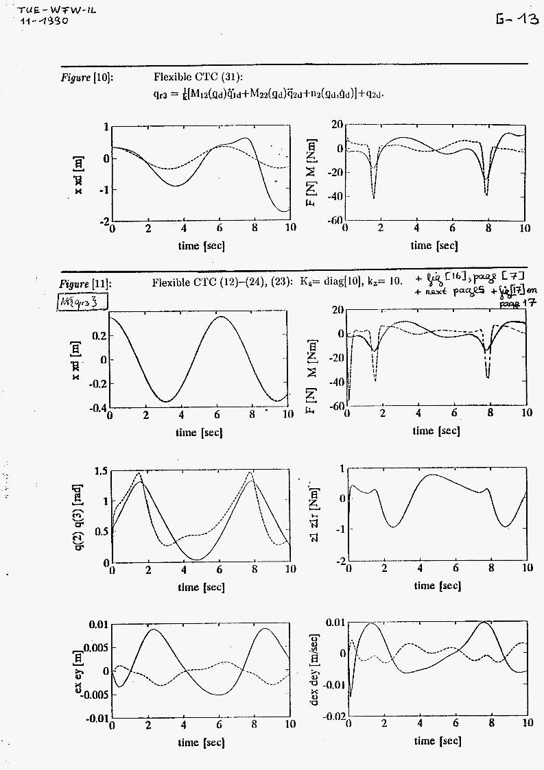
-Tu€- Wrw-Ik I I -4S30
1 I I I 20 I I I I
L I 1 1 1 l
0 2 4 6 8 10 -6flo 2 4 6 8 i o -2 -
time (sec) time [sec]
Figure [li]: Flexible CTC (12)-(24), (23): Ks= diag[iO], kz= io. 3- %
time [sec] time [sec]
time [sec] time [sec]
I 1
-
a 1 I
-0.Ol0 2 4 hi 8 i0 2 4 6 8 10 -0.02()
time [sec] time (sec]

T U E -WTWW-lL 44 - 459 o G - 14
Figure [12]: Flexible CTC (12)-(24), (23): &= O, k, = 10. p @ y r 3 3 1 0.5 I I I I 20 I I I s
Tr 'si U
K
time [sec] time [sec]
0.1 I I I I I
L I 1 1 J 1
-0.050 2 4 6 8 10 2 4 6 8 10 time [sec] time [sec]
Figure [ 131: Flexible CTC (12)-(24), (23): Ks= diag[lO], k,= O. 1 M Z T r a j J
time [sec] time [sec]

[sas] awy
r I 1 I
OT 8 9 P Z
9 \
- - oz- K n
[sas] amp
Ogl-
I I I I I '1 e0Tx
pas] amp OT 8 9 P 2 I I 1
OT-
O
OT
-z
[sas] amy
, , I I IP'O- OT 8 9 P 2
x
n
B Y
9- -17

I 1
Fàgure {14]: Ks = O, kz = O.
w n
0.5 I I 1 I I I Ir x 2 E
U
U
c4 I 1 1 I 1
-60; 2 4 6 8 10 time [sec] time [sec]
F u
t? o -0.05 -
-0.1 I
1 I I I I 1 L I 6 8 10 -20 2 4 6 8 io o . 2 4 time [sec] time [sec]
Figure [15]: K6 = diag[lO], k, = 10. J M S ~ ~ S I I I I I
J -an 2 4 6 0 1 u
-0.41 u
I I I I I
time [sec] time [S IC ]
time (sec] time [sec]

G -13
l i * 1 I I I
time [sec]
I -lo001 O 2 - 4 6 8 10
time [sec]
F x U
d
5 , I I I I 1
-5 o~
TI -lol , , , , 1 10 -15 O 2 4 6 8
time [sec]
2 4 6 8 10 time [sec]
0.01 I I I
L
5
1
2 4 6 - 8 10 2 4 6 8 10 -0.02* -O.0lo
time [sec] time [sec]

I '02
r ?1 CI
OOT o8 m O2
;o
I;"" 40 I i1
,
t? N 1 * z 3 U
I u
1 oz- OT-
O
. AJ n
z Y
i ' 10.0
f=l amfi
%'o- OOT o8 o9 m 02 I

I ’ o2
Crl
z CI
d
z z 3 U
J
s
3 Y
T-
O
.. I
N ci
N ci 1 c1
Y 3”

tu e-wfw-il-i990 H-1
F-( 1) :
+ 1 I I
M(Q)ii + E(Q,il,t) = Hu 7
H TWO-SUBMODEL BASED COMPUTED TORQUE CONTROL OF ELASTIC-JOINT ROBOTS.
I I
H. i Introduction.
In contradiction to chapter F, in this chapter there is not the restriciton that joints have to be elastic (n=2m): n52m.
motor
(1)
page [ G-21: The 3-degrees-of-freedom (DOF) translation-totatdn (TR-) ro
The equations of motion for a manipulator system with linear elastic 'oints are: I
- ux are the rigid-joint actuator forces/torques, - z are the elastic forces/torques
between the links and motors.
F-(18):
F-(19):
-
M (z)Z + 0 (z,$ = z X X -f
/ArZ+JZ+g + z =u z -f Z Z
In the example of the 3-DOF elastic-joint TR-robot:

tue-wfw-il-1990 H-2
H.3 Elastic-ioint robot control.
The reference forces /toraues required for manipulating the rigid links along the desired trajectory:
(10) r r r X F-( 24) :
In the case of the example, the 'rigid' computed torque force is: G( 12): Fr = Mi1 (qsí+Ksííesí) +Mí2( qs2+Ksi#s2) 7
while the 'reference manifold' is also calculated on-line with: G(13): zr = Mia(qsi+Ks2iesl)+M22(qs2+Ks22es2).
Then, the two-submodel based computed torque control law will be:
F-( 33):
F-( 2 1) :
where the computed torque control part:
- u r z r = J ( % + K e ) + ~ ~ + z f i = r r
=[M x +J](Z++Ke)+o z r r r X + E Z (12)
the flexible computed torque control part:
F-( 33) U =J(E z -fr + K e z-zf ) (13)
Finally, the eqUivakat aïoï eqdatim cf heth S~bSystPrns wre:
e = z -z = M ( e + K e ) -zf -fr -f x r i r
p J ( ë + K e ) + J ( e + K e ) z r r r
F-( 18) / (24, G( 15) / (16) :
z 'Zf z-zf F-(19)/(33), G(21):
The error eauations of the total closed-loor, svstem are:
(14)
+ e = O (15) Z f -
F-( 36), G( 22) 1 1 (16)