addendum #1 sm rcu parking lot & ada … · 212.25 inv (213.01) inv 213.64 tg 212.14 inv 213.25...
TRANSCRIPT

Page 1 of 3
Addendum #1 SM RCU Parking Lot & ADA Improvements Project
116 West Agnes Avenue, Santa Maria, CA 93459 County Project #8764
County of Santa Barbara, General Services Department
Capital Projects 1105 Santa Barbara Street, 2nd Floor Santa Barbara, California, CA 93101
August 6, 2018
To: All Planholders and Bidders From: County of Santa Barbara General Services Department Phone: (805) 934-6228 GENERAL This Addendum and all attachments mentioned herein, are hereby made a part of the Contract Documents to the same extent as though they were originally included therein; all other conditions shall remain the same. Bidders are required to acknowledge receipt of this addendum in the space provided in the proposal. Item No.
1. Bid RFI 001: Question: The plans call out for a new masonry wall along the west side of the property. However, there is an existing masonry wall there already. Please clarify note 7 in this area! Response: The note reference #7 is incorrect. The existing masonry wall will remain. Question: Are there to be 2 gates attached to the new wall, one in front and one in the back-plans only call out for one gate in the back. Please clarify! Response: There are two gates indicated on the site plan. One at the building entry and the other near the trash enclosure. Question: What type of gates are required? Chain-link or wood? Please clarify! Response: Chain link with slat inserts. Question: Are the benches called out for on the plans by the civil contractor or by the building remodeling contractor? If they are by the civil contractor, please provide a detail of the bench and the quantity required. Response: All site work is part of this contract. Benches will be by owner’s FE&E vendor. Question: Can the car bumper stops be glued down to the pavers? Response: No. Question: Is stall striping required? Response: Yes. Question: Is the new masonry wall to be 5' or 6' high? Response: 6’.
Page 2 of 3
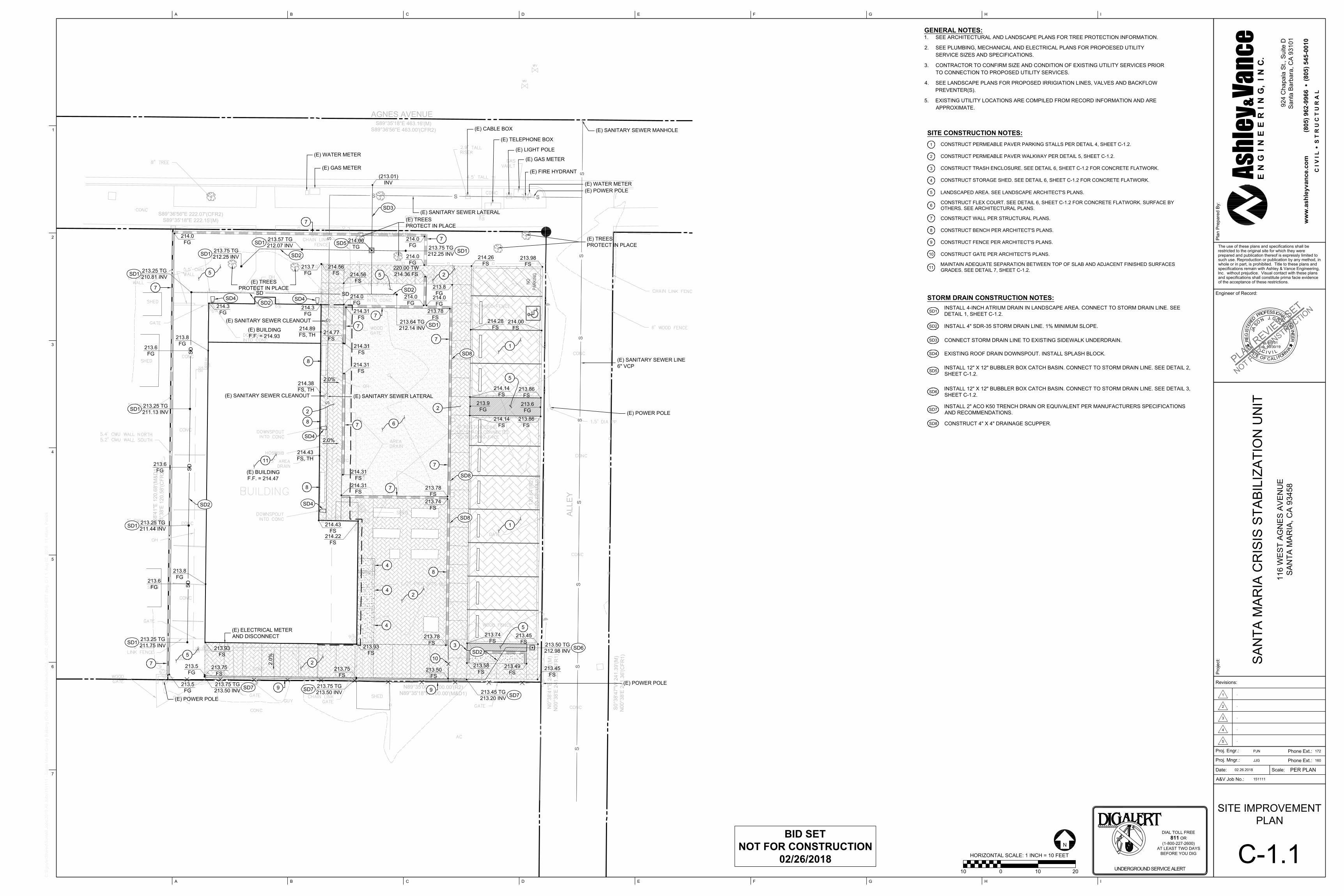
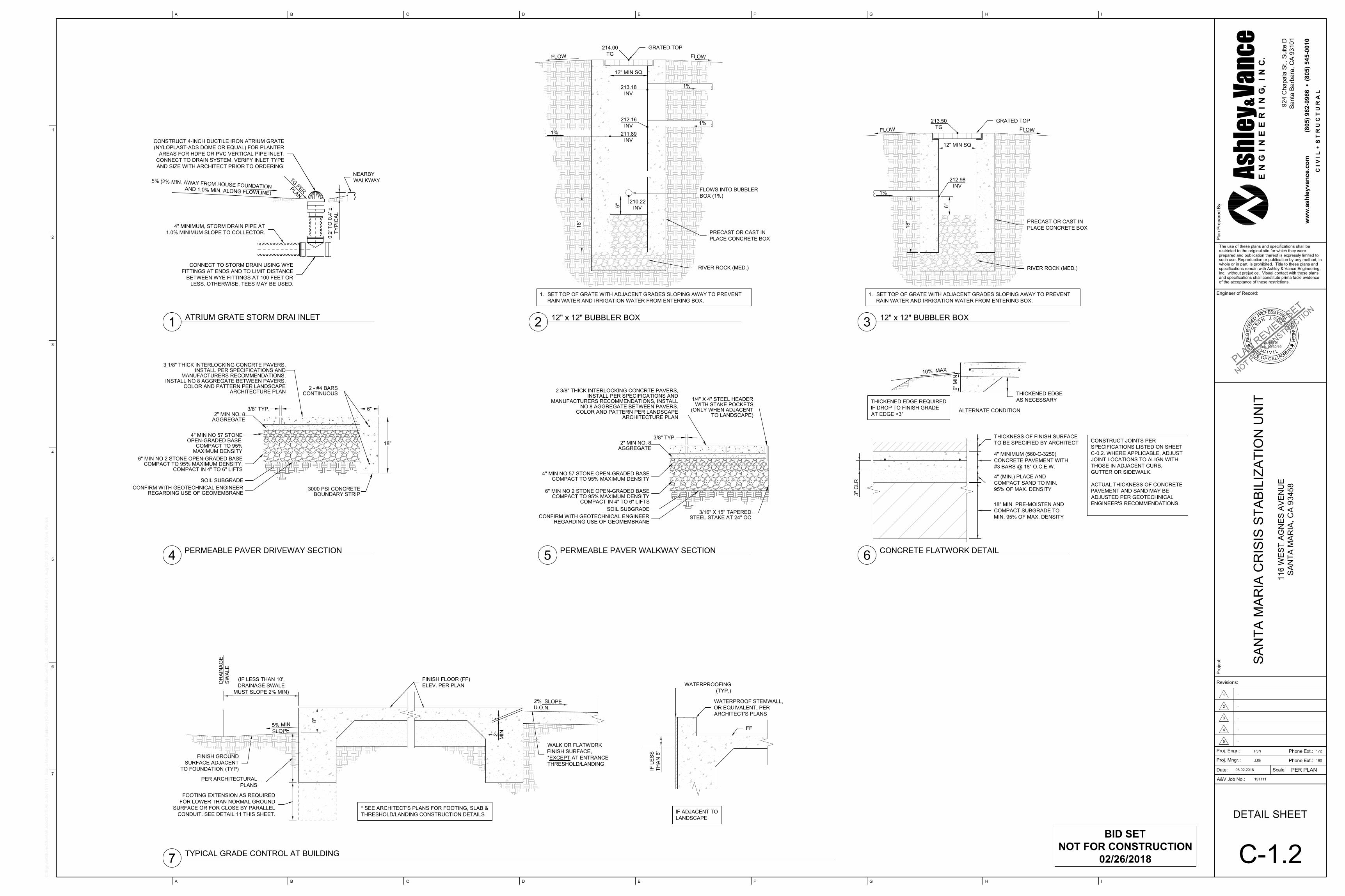
Question: Is the concrete under the new storage are by civil or building contractor? Please clarify! Response: Concrete work under new storage area is by building contractor, not part of this contract. Question: Are we to build this new storage area or is this being done by building contractor? This work should in in building contractors scope. Please clarify! Response: This scope is by the building contractor, not part of this contract. Question: On sheet C 1.1, there are 3 call outs for SD-8.( 4 x 4 drainage scuppers), do you want us to leave a 4 x 4 opening in the bottom course of the new masonry wall for the water to leave the courtyard are and drain to the alley? Please clarify! Response: Yes. Question: Again on sheet C 1.1, the plans call out for 2-6" posts to hold up the new shade structure that is connected to the building structure. Is this work, posts and shade structure part of the civil or is this work covered in the building contractor’s scope? Please clarify! Response: Scope is part of this contract. Contract scope also includes the complete Shade Structure. Question: Again on sheet C 1.1, there is a call out for a 6' wood fence. Does this fence extend from the new masonry wall to the east property line at the alley? Please clarify! Response: There is an existing fence to remain. Complete the line of fence as required to secure the site. Question: Is there any electrical work being done under this contract or is included the building scope of work? Please clarify! Response: Yes. All site lighting or signage as indicated on the drawings is part of this contract. Question: Specs call out for a "B" license when this is clearly a general engineering or class "A" scope of work. Is a class "A" license acceptable? Please clarify! Response: Either a class “A” or class “B” license is required for this project. Question: In the courtyard area, there is a call out for 2 area drains but plans do not show any storm drain lines connecting the 2 boxes or any lines discharging to the new storm drain facilities. Please clarify! Response: These yard drains should daylight at the curb via a drain line underground. 2. Bid RFI 002: Question: On detail 4, sheet C 1.2, where does the concrete boundry apply? There are no sections on plans that show where to start & stop concrete. Please clarify! Answer: Concrete boundary strip should be constructed around the entire perimeter of the permeable driveway. See revised site improvement plan (C-1.1) and detail sheet (C-1.2).
Question: On detail 5, sheet C 1.2, where does the steel header apply? Same as above, no sections showing where to start & stop. Please clarify! Answer: Steel header should be constructed where the permeable walkway is adjacent to landscaped areas only. See revised detail sheet (C-1.2).
Question: Please confirm that the concrete courtyard is 6" concrete over 4" sand. Is there going to be a finished surface other than concrete? If so, what material will be placed on top of the concrete and what will be the thickness of the material? Are there any deep score/cold joints/sawcuts required on the courtyard area? Answer: No finish material is planned on top of this concrete slab. Provide brushed finish. Joints are to be constructed per “Driveway Pavement and Appurtenant Concrete” Note #11 on sheet C-0.2. Question: Is there a new 6' wood fence along the south property line or is the existing fence staying? There is a note on the plans with an arrow pointing to the south property line stating 6' wood fence. Please clarify! Answer: The south fence is to remain.
Page 3 of 3
Question: Is the excess dirt coming off of the project the contractor's responsibility to dispose of or does the county have a location for stockpile of this material? Answer: Contractor is responsible.
Question: Will the county provide survey or is it our responsibility? Answer: The County has the survey.
Question: Are the building remodel and the civil portion going to be done at the same time? Answer: Yes.
Question: Will the county furnish water at the existing hose bibbs for construction purposes? Answer: Yes.
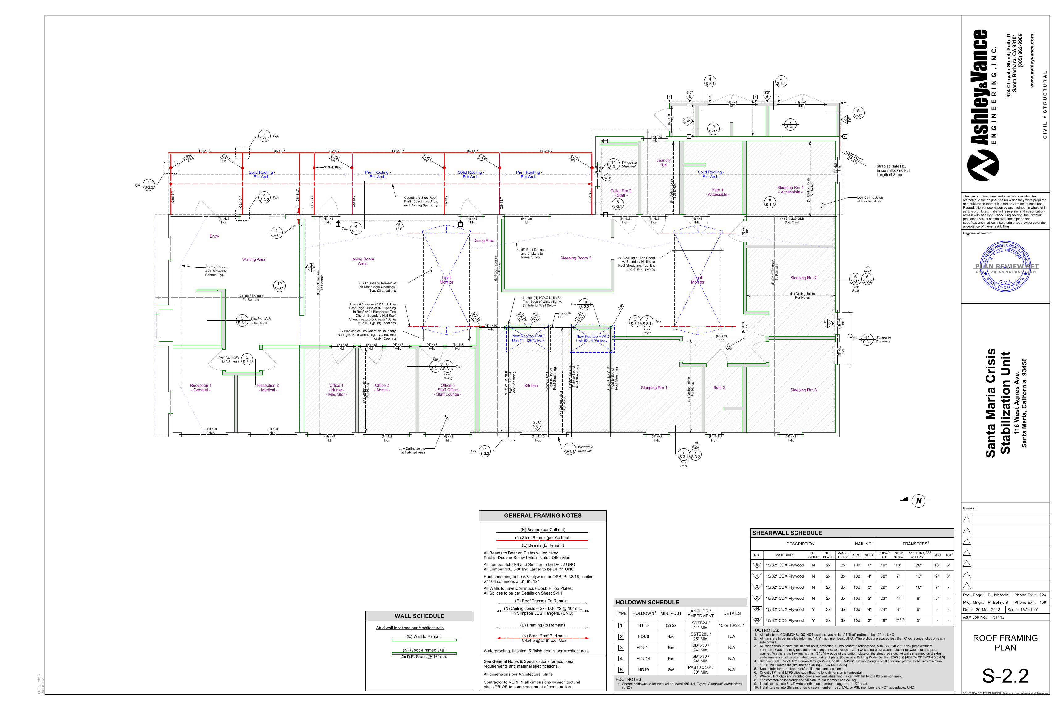
Question: Are the grates on the 2 bubbler DI's to be bolt down and ADA? Answer: Yes. 3. Bid RFI 003: Question: On S-2.1 CMU wall calling out pipe columns in 7 locations? Is this CMU wall required in bid? Please advise? Answer: Yes, scope is part of this contract. Question: On S-2.1 Pipe Columns Per S-2.2 Typ. (7) Locations- Sheet S2.2 is not in plans. Please advise? Answer: See attached Sheet S-2.2. Question: On A1.01 (E) Overflow drain scupper and downspout to be removed and replaced. Is this required in bid? Please advise? Answer: This scope is by the building contractor, not part of this contract. Question: On A1.0 is calling out new benches- No specs specified- Please advise? Answer: Benches will be by owner’s FE&E vendor.
4. Bid RFI 004: Question: Can you tell me if a bid bond is required for this project? Answer: Yes. Refer to attached Bid Bond form.
AGNES AVENUE
ALLE
Y
S0
°3
8'4
7"W
2
41
.3
9'(M
)
N0
0°3
8'E
2
41
.3
6'(C
FR
1)
S89°35'18"E 463.16'(M)
S89°36'56"E 463.00'(CFR2)
S89°36'56"E 222.07'(CFR2)
S89°35'18"E 222.15'(M)
N0
°3
8'4
1"E
2
41
.3
8'(M
)
N0
0°3
8'E
2
41
.3
5'(C
FR
1)
100.00'(M,D1&R2)
12
0.64
'(R
2)
120.68'(M
&D
1)
N0
°3
8'4
1"E
1
20
.6
8'(M
&D
1)
N0
0°3
8'E
1
20
.5
8'(C
FR
2)
N89°35'00"W 100.00'(R2)
N89°35'18"W 100.00'(M&D1)
2
2
0
.
2
2
B
L
D
G
218.72
BLDG
2
1
8
.7
7
B
L
D
G
2
1
8
.6
6
B
L
D
G
222.62
OH
225.79
OH
225.32
OH
214.48
GATE
2
1
4
.
5
1
B
L
D
G
2
1
3
.
8
9
F
D
2
.
5
"
B
C
A
P
214.92
BLDG
213.85
CO
NC
225.51
OH
224.73
BLDG
223.53
BLDG
2
2
2
.
5
4
B
L
D
G
222.63
B
LD
G
2
2
3
.
3
0
B
L
D
G
2
1
4
.
0
0
214.00
2
1
4
.
0
0
2
1
4
.0
0
2
1
4
.0
0
214.00
NOPA
RKIN
G
SD
SD
SD
SD
SD
S
S
S
S
S
S
S
S
S
S
S
S
S
S
(E) BUILDING
F.F. = 214.93
214.0
FG
213.5
FG
213.7
FG
214.0
FG
214.3
FG
214.0
FG
213.78
FS
213.78
FS
213.50
FS
213.75
FS
213.93
FS
214.43
FS
214.56
FS
214.14
FS
213.74
FS
214.14
FS
213.58
FS
213.49
FS
214.26
FS
213.45
FS
213.86
FS
213.98
FS
213.86
FS
214.0
FG
214.0
FG
214.56
FS
213.9
FG
213.6
FG
214.22
FS
213.93
FS
213.75 TG
212.25 INV
(213.01)
INV
213.64 TG
212.14 INV
213.25 TG
210.81 INV
213.25 TG
211.13 INV
213.25 TG
211.44 INV
213.25 TG
211.75 INV
213.6
FG
214.31
FS
214.31
FS
214.31
FS
214.31
FS
214.31
FS
213.5
FG
213.78
FS
213.74
FS
220.00 TW
214.36 FS
2.0%
2.0%
2.0%
213.50 TG
212.98 INV
214.77
FS
213.45 TG
213.20 INV
213.75 TG
213.50 INV
214.3
FG
S
S
S
S
S
S
S
S
214.38
FS, TH
214.43
FS, TH
214.89
FS, TH
(E) BUILDING
F.F. = 214.47
S
S
S
S
S
S
213.75 TG
212.25 INV
213.8
FG
213.6
FG
213.6
FG
213.8
FG
213.57 TG
212.07 INV
214.00
TG
214.0
FG
213.8
FG
213.45
FS
214.28
FS
214.00
FS
213.75 TG
213.50 INV
213.75
FS
Pro
je
ct:
Revisions:
Proj. Engr.:
Proj. Mngr.:
Date:
A&V Job No.:
Scale:PER PLAN
A B C D E F G H I
A B C D E F G H I
1
2
3
4
5
6
7
C:\E
gnyte\S
hared\S
un\A
ll Jobs\2015 A
ll Jobs\151111 - S
anta M
aria C
ounty B
uilding (C
ivil) - B
ildsten A
rchitecture\02_cad\02_O
NS
IT
E\G
RA
DIN
G S
HE
ET
.dw
g, C
-1.1, A
ug 02, 2018 11:48am
, P
atrick
Engineer of Record:
Pla
n P
re
pa
re
d B
y:
The use of these plans and specifications shall be
restricted to the original site for which they were
prepared and publication thereof is expressly limited to
such use. Reproduction or publication by any method, in
whole or in part, is prohibited. Title to these plans and
specifications remain with Ashley & Vance Engineering,
Inc. without prejudice. Visual contact with these plans
and specifications shall constitute prima facie evidence
of the acceptance of these restrictions.
Ashl
ey&V
ance
EN
GIN
EE
RIN
G, IN
C.
ww
w.a
sh
le
yv
an
ce
.c
om
C I V
I L
S
T
R
U
C
T
U
R
A
L
EE
N
I
No. 65701
T
S
C
T
A
E
F
O
I
GE
R
A
I
O
F
I
L
AC
L
IV N
R
R
E
R
P
J
A
S
O
N
J.G
O
T
S
I
S
S
D
E
R
E
T
F
O
N
O
I
L
A
G
N
E
I
SS
Exp. 09/30/19
92
4 C
ha
pa
la
S
t., S
uite
D
Sa
nta
B
arb
ara
, C
A 9
31
01
(8
05
) 9
62
-9
96
6 (8
05
) 5
45
-0
01
0
P
L
A
N
R
E
V
I
E
W
S
E
T
N
O
T
F
O
R
C
O
N
S
T
R
U
C
T
I
O
N
Phone Ext.:
Phone Ext.:
SA
NT
A M
AR
IA
C
RIS
IS
S
TA
BILIZ
AT
IO
N U
NIT
11
6 W
ES
T A
GN
ES
A
VE
NU
E
SA
NT
A M
AR
IA
, C
A 9
34
58
PJN
JJG
02.26.2018
151111
SITE IMPROVEMENT
PLAN
C-1.1
1
.
2
.
3
.
4
.
5
.
172
160
GENERAL NOTES:
1. SEE ARCHITECTURAL AND LANDSCAPE PLANS FOR TREE PROTECTION INFORMATION.
2. SEE PLUMBING, MECHANICAL AND ELECTRICAL PLANS FOR PROPOESED UTILITY
SERVICE SIZES AND SPECIFICATIONS.
3. CONTRACTOR TO CONFIRM SIZE AND CONDITION OF EXISTING UTILITY SERVICES PRIOR
TO CONNECTION TO PROPOSED UTILITY SERVICES.
4. SEE LANDSCAPE PLANS FOR PROPOSED IRRIGIATION LINES, VALVES AND BACKFLOW
PREVENTER(S).
5. EXISTING UTILITY LOCATIONS ARE COMPILED FROM RECORD INFORMATION AND ARE
APPROXIMATE.
SITE CONSTRUCTION NOTES:
CONSTRUCT PERMEABLE PAVER PARKING STALLS PER DETAIL 4, SHEET C-1.2.
CONSTRUCT PERMEABLE PAVER WALKWAY PER DETAIL 5, SHEET C-1.2.
CONSTRUCT TRASH ENCLOSURE. SEE DETAIL 6, SHEET C-1.2 FOR CONCRETE FLATWORK.
CONSTRUCT STORAGE SHED. SEE DETAIL 6, SHEET C-1.2 FOR CONCRETE FLATWORK.
LANDSCAPED AREA. SEE LANDSCAPE ARCHITECT'S PLANS.
CONSTRUCT FLEX COURT. SEE DETAIL 6, SHEET C-1.2 FOR CONCRETE FLATWORK. SURFACE BY
OTHERS. SEE ARCHITECTURAL PLANS.
CONSTRUCT WALL PER STRUCTURAL PLANS.
CONSTRUCT BENCH PER ARCHITECT'S PLANS.
CONSTRUCT FENCE PER ARCHITECT'S PLANS.
CONSTRUCT GATE PER ARCHITECT'S PLANS.
MAINTAIN ADEQUATE SEPARATION BETWEEN TOP OF SLAB AND ADJACENT FINISHED SURFACES
GRADES. SEE DETAIL 7, SHEET C-1.2.
1
2
3
4
5
6
7
8
9
10
11
STORM DRAIN CONSTRUCTION NOTES:
INSTALL 4-INCH ATRIUM DRAIN IN LANDSCAPE AREA. CONNECT TO STORM DRAIN LINE. SEE
DETAIL 1, SHEET C-1.2.
INSTALL 4" SDR-35 STORM DRAIN LINE. 1% MINIMUM SLOPE.
CONNECT STORM DRAIN LINE TO EXISTING SIDEWALK UNDERDRAIN.
EXISTING ROOF DRAIN DOWNSPOUT. INSTALL SPLASH BLOCK.
INSTALL 12" X 12" BUBBLER BOX CATCH BASIN. CONNECT TO STORM DRAIN LINE. SEE DETAIL 2,
SHEET C-1.2.
INSTALL 12" X 12" BUBBLER BOX CATCH BASIN. CONNECT TO STORM DRAIN LINE. SEE DETAIL 3,
SHEET C-1.2.
INSTALL 2" ACO K50 TRENCH DRAIN OR EQUIVALENT PER MANUFACTURERS SPECIFICATIONS
AND RECOMMENDATIONS.
CONSTRUCT 4" X 4" DRAINAGE SCUPPER.
SD1
SD2
SD3
SD4
SD5
SD6
SD7
SD8
010 10 20
HORIZONTAL SCALE: 1 INCH = 10 FEET
N
DIAL TOLL FREE
811 OR
(1-800-227-2600)
AT LEAST TWO DAYS
BEFORE YOU DIG
UNDERGROUND SERVICE ALERT
SD8
SD8
SD8
SD7
SD7
SD6
1
1
2
2
2
6
SD1
SD1
SD1
SD1
SD1
SD5
SD1
2
2
SD2
SD2
SD3
SD2
SD2
SD2
7
7
7
7
7
7
8
3
7
7
7
7
8
8
8
4
4
4
SD4
SD4
SD4
SD4
5
5
5
5
5
9
9
(E) ELECTRICAL METER
AND DISCONNECT
10
(E) TREES
PROTECT IN PLACE
(E) TREES
PROTECT IN PLACE
(E) TREES
PROTECT IN PLACE
(E) POWER POLE
(E) POWER POLE
(E) POWER POLE
(E) WATER METER
(E) GAS METER
(E) LIGHT POLE
(E) TELEPHONE BOX
(E) CABLE BOX
(E) FIRE HYDRANT
(E) GAS METER
(E) WATER METER
(E) POWER POLE
(E) SANITARY SEWER LINE
6" VCP
(E) SANITARY SEWER MANHOLE
(E) SANITARY SEWER LATERAL
(E) SANITARY SEWER CLEANOUT
(E) SANITARY SEWER CLEANOUT
(E) SANITARY SEWER LATERAL
SD1
SD1
11
BID SET
NOT FOR CONSTRUCTION
02/26/2018
SD7
Pro
je
ct:
Revisions:
Proj. Engr.:
Proj. Mngr.:
Date:
A&V Job No.:
Scale:PER PLAN
A B C D E F G H I
A B C D E F G H I
1
2
3
4
5
6
7
C:\E
gnyte\S
hared\S
un\A
ll Jobs\2015 A
ll Jobs\151111 - S
anta M
aria C
ounty B
uilding (C
ivil) - B
ildsten A
rchitecture\02_cad\02_O
NS
IT
E\D
ET
AIL S
HE
ET
.dw
g, C
-2.1, A
ug 02, 2018 11:47am
, P
atrick
Engineer of Record:
Pla
n P
re
pa
re
d B
y:
The use of these plans and specifications shall be
restricted to the original site for which they were
prepared and publication thereof is expressly limited to
such use. Reproduction or publication by any method, in
whole or in part, is prohibited. Title to these plans and
specifications remain with Ashley & Vance Engineering,
Inc. without prejudice. Visual contact with these plans
and specifications shall constitute prima facie evidence
of the acceptance of these restrictions.
Ashl
ey&V
ance
EN
GIN
EE
RIN
G, IN
C.
ww
w.a
sh
le
yv
an
ce
.c
om
C I V
I L
S
T
R
U
C
T
U
R
A
L
EE
N
I
No. 65701
T
S
C
T
A
E
F
O
I
GE
R
A
I
O
F
I
L
AC
L
IV N
R
R
E
R
P
J
A
S
O
N
J.G
O
T
S
I
S
S
D
E
R
E
T
F
O
N
O
I
L
A
G
N
E
I
SS
Exp. 09/30/19
92
4 C
ha
pa
la
S
t., S
uite
D
Sa
nta
B
arb
ara
, C
A 9
31
01
(8
05
) 9
62
-9
96
6 (8
05
) 5
45
-0
01
0
P
L
A
N
R
E
V
I
E
W
S
E
T
N
O
T
F
O
R
C
O
N
S
T
R
U
C
T
I
O
N
Phone Ext.:
Phone Ext.:
SA
NT
A M
AR
IA
C
RIS
IS
S
TA
BILIZ
AT
IO
N U
NIT
11
6 W
ES
T A
GN
ES
A
VE
NU
E
SA
NT
A M
AR
IA
, C
A 9
34
58
PJN
JJG
08.02.2018
151111
DETAIL SHEET
C-1.2
1
.
2
.
3
.
4
.
5
.
172
160
12" MIN SQ
GRATED TOP
RIVER ROCK (MED.)
PRECAST OR CAST IN
PLACE CONCRETE BOX
1. SET TOP OF GRATE WITH ADJACENT GRADES SLOPING AWAY TO PREVENT
RAIN WATER AND IRRIGATION WATER FROM ENTERING BOX.
FLOW
FLOW
18
"
6"
213.18
INV
211.89
INV
210.22
INV
1%
1%
FLOWS INTO BUBBLER
BOX (1%)
214.00
TG
2
12" x 12" BUBBLER BOX
12" MIN SQ
GRATED TOP
RIVER ROCK (MED.)
PRECAST OR CAST IN
PLACE CONCRETE BOX
1. SET TOP OF GRATE WITH ADJACENT GRADES SLOPING AWAY TO PREVENT
RAIN WATER AND IRRIGATION WATER FROM ENTERING BOX.
FLOW
FLOW
18
"
6"
212.98
INV
1%
213.50
TG
3
12" x 12" BUBBLER BOX
1
0.2
' T
O 0
.4
' ±
TY
PIC
AL
CONSTRUCT 4-INCH DUCTILE IRON ATRIUM GRATE
(NYLOPLAST-ADS DOME OR EQUAL) FOR PLANTER
AREAS FOR HDPE OR PVC VERTICAL PIPE INLET.
CONNECT TO DRAIN SYSTEM. VERIFY INLET TYPE
AND SIZE WITH ARCHITECT PRIOR TO ORDERING.
NEARBY
WALKWAY
CONNECT TO STORM DRAIN USING WYE
FITTINGS AT ENDS AND TO LIMIT DISTANCE
BETWEEN WYE FITTINGS AT 100 FEET OR
LESS. OTHERWISE, TEES MAY BE USED.
4" MINIMUM, STORM DRAIN PIPE AT
1.0% MINIMUM SLOPE TO COLLECTOR.
5% (2%
MIN
. AWAY FR
OM
HO
USE FO
UN
DATIO
N
AND
1.0% M
IN. ALO
NG
FLOW
LINE)
T
G
P
E
R
P
L
A
N
ATRIUM GRATE STORM DRAI INLET
212.16
INV
1%
4
PERMEABLE PAVER DRIVEWAY SECTION
5
PERMEABLE PAVER WALKWAY SECTION
4" MIN NO 57 STONE OPEN-GRADED BASE
COMPACT TO 95% MAXIMUM DENSITY
2" MIN NO. 8
AGGREGATE
6" MIN NO 2 STONE OPEN-GRADED BASE
COMPACT TO 95% MAXIMUM DENSITY
COMPACT IN 4" TO 6" LIFTS
SOIL SUBGRADE
2 3/8" THICK INTERLOCKING CONCRTE PAVERS,
INSTALL PER SPECIFICATIONS AND
MANUFACTURERS RECOMMENDATIONS, INSTALL
NO 8 AGGREGATE BETWEEN PAVERS.
COLOR AND PATTERN PER LANDSCAPE
ARCHITECTURE PLAN
4" MIN NO 57 STONE
OPEN-GRADED BASE.
COMPACT TO 95%
MAXIMUM DENSITY
2" MIN NO. 8
AGGREGATE
6" MIN NO 2 STONE OPEN-GRADED BASE
COMPACT TO 95% MAXIMUM DENSITY.
COMPACT IN 4" TO 6" LIFTS
2 - #4 BARS
CONTINUOUS
6"
18"
3000 PSI CONCRETE
BOUNDARY STRIP
3 1/8" THICK INTERLOCKING CONCRTE PAVERS,
INSTALL PER SPECIFICATIONS AND
MANUFACTURERS RECOMMENDATIONS,
INSTALL NO 8 AGGREGATE BETWEEN PAVERS.
COLOR AND PATTERN PER LANDSCAPE
ARCHITECTURE PLAN
3/16" X 15" TAPERED
STEEL STAKE AT 24" OC
1/4" X 4" STEEL HEADER
WITH STAKE POCKETS
(ONLY WHEN ADJACENT
TO LANDSCAPE)
3/8" TYP.
3/8" TYP.
1 2
"
MIN
.
* SEE ARCHITECT'S PLANS FOR FOOTING, SLAB &
THRESHOLD/LANDING CONSTRUCTION DETAILS
FINISH GROUND
SURFACE ADJACENT
TO FOUNDATION (TYP)
FINISH FLOOR (FF)
ELEV. PER PLAN
WALK OR FLATWORK
FINISH SURFACE,
*EXCEPT AT ENTRANCE
THRESHOLD/LANDING
5% M
IN
SLOPE
8"
(IF LESS THAN 10',
DRAINAGE SWALE
MUST SLOPE 2% MIN)
DR
AIN
AG
E
SW
AL
E
2% SLOPE
U.O.N.
PER ARCHITECTURAL
PLANS
TYPICAL GRADE CONTROL AT BUILDING
FOOTING EXTENSION AS REQUIRED
FOR LOWER THAN NORMAL GROUND
SURFACE OR FOR CLOSE BY PARALLEL
CONDUIT. SEE DETAIL 11 THIS SHEET.
7
IF ADJACENT TO
LANDSCAPE
WATERPROOF STEMWALL,
OR EQUIVALENT, PER
ARCHITECT'S PLANS
WATERPROOFING
(TYP.)
FF
IF
L
ES
S
TH
AN
6
"
6
ALTERNATE CONDITION
THICKENED EDGE REQUIRED
IF DROP TO FINISH GRADE
AT EDGE >3"
6" M
IN
THICKENED EDGE
AS NECESSARY
4" MINIMUM (560-C-3250)
CONCRETE PAVEMENT WITH
#3 BARS @ 18" O.C.E.W.
4" (MIN.) PLACE AND
COMPACT SAND TO MIN.
95% OF MAX. DENSITY
18" MIN. PRE-MOISTEN AND
COMPACT SUBGRADE TO
MIN. 95% OF MAX. DENSITY
3" C
LR
10%
M
AX
THICKNESS OF FINISH SURFACE
TO BE SPECIFIED BY ARCHITECT
CONCRETE FLATWORK DETAIL
CONFIRM WITH GEOTECHNICAL ENGINEER
REGARDING USE OF GEOMEMBRANE
SOIL SUBGRADE
CONFIRM WITH GEOTECHNICAL ENGINEER
REGARDING USE OF GEOMEMBRANE
BID SET
NOT FOR CONSTRUCTION
02/26/2018
CONSTRUCT JOINTS PER
SPECIFICATIONS LISTED ON SHEET
C-0.2. WHERE APPLICABLE, ADJUST
JOINT LOCATIONS TO ALIGN WITH
THOSE IN ADJACENT CURB,
GUTTER OR SIDEWALK.
ACTUAL THICKNESS OF CONCRETE
PAVEMENT AND SAND MAY BE
ADJUSTED PER GEOTECHNICAL
ENGINEER'S RECOMMENDATIONS.
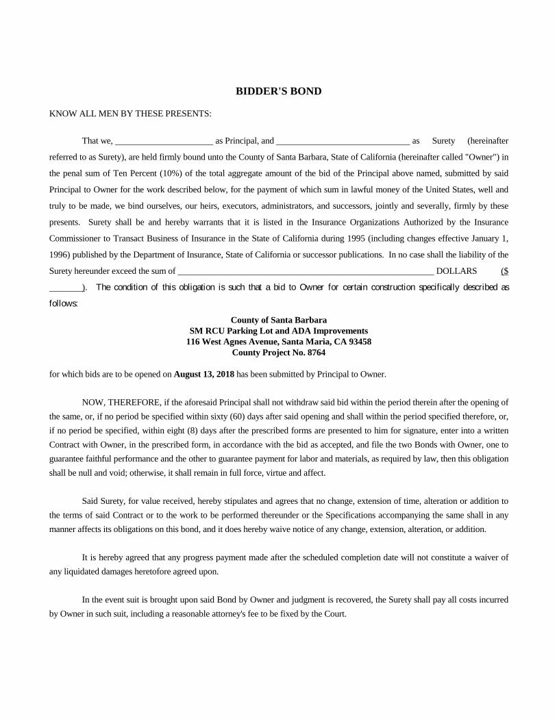
BIDDER'S BOND
KNOW ALL MEN BY THESE PRESENTS:
That we, as Principal, and as Surety (hereinafter
referred to as Surety), are held firmly bound unto the County of Santa Barbara, State of California (hereinafter called "Owner") in
the penal sum of Ten Percent (10%) of the total aggregate amount of the bid of the Principal above named, submitted by said
Principal to Owner for the work described below, for the payment of which sum in lawful money of the United States, well and
truly to be made, we bind ourselves, our heirs, executors, administrators, and successors, jointly and severally, firmly by these
presents. Surety shall be and hereby warrants that it is listed in the Insurance Organizations Authorized by the Insurance
Commissioner to Transact Business of Insurance in the State of California during 1995 (including changes effective January 1,
1996) published by the Department of Insurance, State of California or successor publications. In no case shall the liability of the
Surety hereunder exceed the sum of DOLLARS ($
). The condition of this obligation is such that a bid to Owner for certain construction specifically described as
follows:
County of Santa Barbara SM RCU Parking Lot and ADA Improvements
116 West Agnes Avenue, Santa Maria, CA 93458 County Project No. 8764
for which bids are to be opened on August 13, 2018 has been submitted by Principal to Owner. NOW, THEREFORE, if the aforesaid Principal shall not withdraw said bid within the period therein after the opening of the same, or, if no period be specified within sixty (60) days after said opening and shall within the period specified therefore, or, if no period be specified, within eight (8) days after the prescribed forms are presented to him for signature, enter into a written Contract with Owner, in the prescribed form, in accordance with the bid as accepted, and file the two Bonds with Owner, one to guarantee faithful performance and the other to guarantee payment for labor and materials, as required by law, then this obligation shall be null and void; otherwise, it shall remain in full force, virtue and affect. Said Surety, for value received, hereby stipulates and agrees that no change, extension of time, alteration or addition to the terms of said Contract or to the work to be performed thereunder or the Specifications accompanying the same shall in any manner affects its obligations on this bond, and it does hereby waive notice of any change, extension, alteration, or addition. It is hereby agreed that any progress payment made after the scheduled completion date will not constitute a waiver of any liquidated damages heretofore agreed upon. In the event suit is brought upon said Bond by Owner and judgment is recovered, the Surety shall pay all costs incurred by Owner in such suit, including a reasonable attorney's fee to be fixed by the Court.

Death, Bankruptcy, Receivership, Going Out of Business for any reason, or incompetence of the Principal shall not relieve the Surety of its obligations hereunder.
Name of Principal
Dated __________________________ (Seal) Signature of Principal
Name of Surety
Address
City, State & Zip Dated __________________________ (Seal) Signature of Principal Signature of Surety’s Attorney-in-fact
Surety’s Agent for Service of Process (located within the State of California): Name of Agent
Address
City, State & Zip
Telephone Number FAX Number NOTE: Signatures of those executing for Surety MUST be properly acknowledged. This form may be reproduced for transmittal to the Surety for execution and attached to the front of the original Bid Bond Form.