addendum no. 2 · carbon steel astm a307 grade a with a tripac 2000 blue coating system. ......
TRANSCRIPT
Addendum No. 2 Mt. Rose Water Treatment Plant
PWP Bid No.: WA-2018-240
TMWA Capital Project No.: 11-0010
Tuesday August 7th, 2018
The following information, clarifications, changes and modifications are by reference incorporated into
the bid documents for the above referenced project. Any work item or contract provision not changed or
modified will remain in full force and effect. The bid date and time and construction schedule have
changed. See Clarification 1 below.
CLARIFICATIONS, QUESTIONS AND RESPONSES, DRAWINGS
AND SPECIFICATIONS
CLARIFICATIONS
Clarification No. 1: The bid opening date has been changed from August 22nd, 2018 to:
August 29th, 2018 at 2 PM.
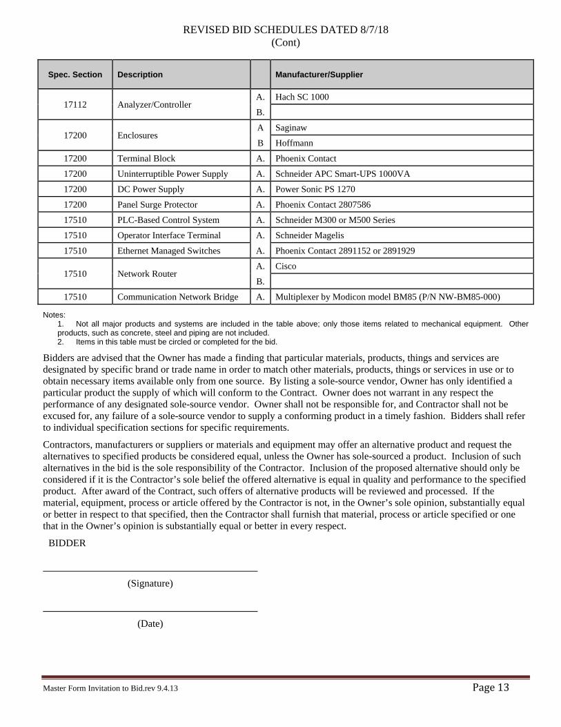
Clarification No. 2: Remove the List of Equipment Manufacturers from the Bid Schedules in its
entirety and replace with the attached Revised Bid Schedules Dated 8/7/18 “List of Equipment
Manufacturers” Section.
Clarification No. 3: Where the M sheets make reference to Detail M301/TYP, the contractor is
instructed to utilize detail M111/TYP found on sheet GM03.
QUESTIONS AND RESPONSES
Question No. 1: Reference specification section 15000 2.2 E 1.i. Flange Fasteners are called out to be
Carbon Steel ASTM A307 Grade A with a TRIPAC 2000 blue coating system. Please confirm Carbon
Steel bolts with TRIPAC 2000 blue coating are to be used for all flange material types whether Ductile
Iron, PVC, CPVC, Stainless Steel or Carbon Steel and the same for all flange locations, specifically
exposed chemical systems and submerged applications. Or should 316 Stainless Steel be used in certain
locations in lieu of the Carbon Steel bolts with TRIPAC 2000 blue coating?
Response to Question No. 1: Please reference specification sections 15000 2.2.E.2, 3, and 4 which
provides further clarification regarding corrosive and non-corrosive service applications, as well as
material groups for various pipe materials.
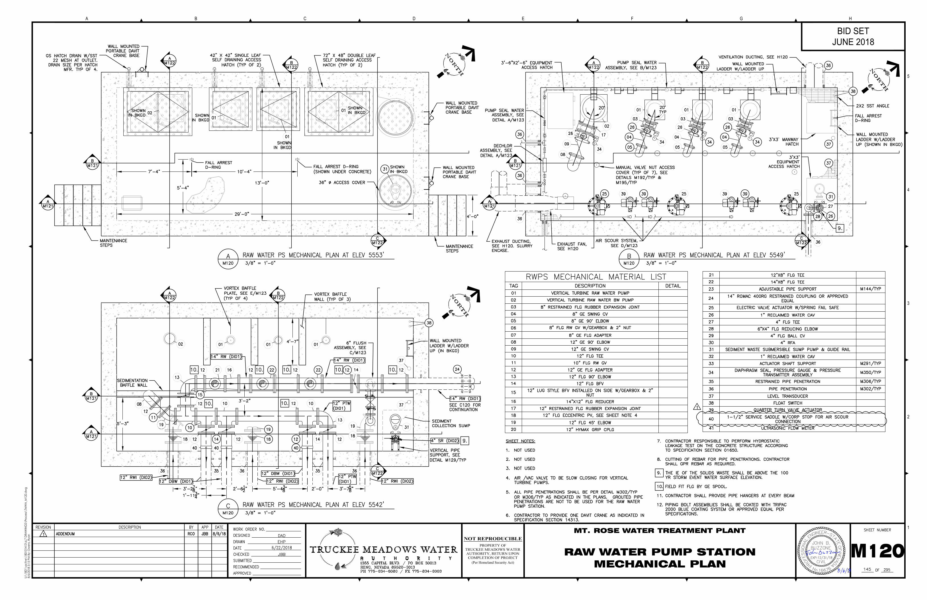
Question No. 2: An air scour assembly is shown on sheet M123 of the plans. Can you confirm that this
assembly begins at the 1-1/2” SST Universal Air Coupler that is not attached to anything and injects into three of
the 12” backwash pipes at the Service Saddle with Corp Stop?
Response to Question No. 2: Confirmed. The system provides a manual air connection point.
Question No. 3: The NDEP permit in Appendix C was listed as valid between August 28th, 2017 and February
24th, 2018. Has this permit been extended to incorporate our project time frame?
Response to Question No. 3: This permit will be extended for the project duration.
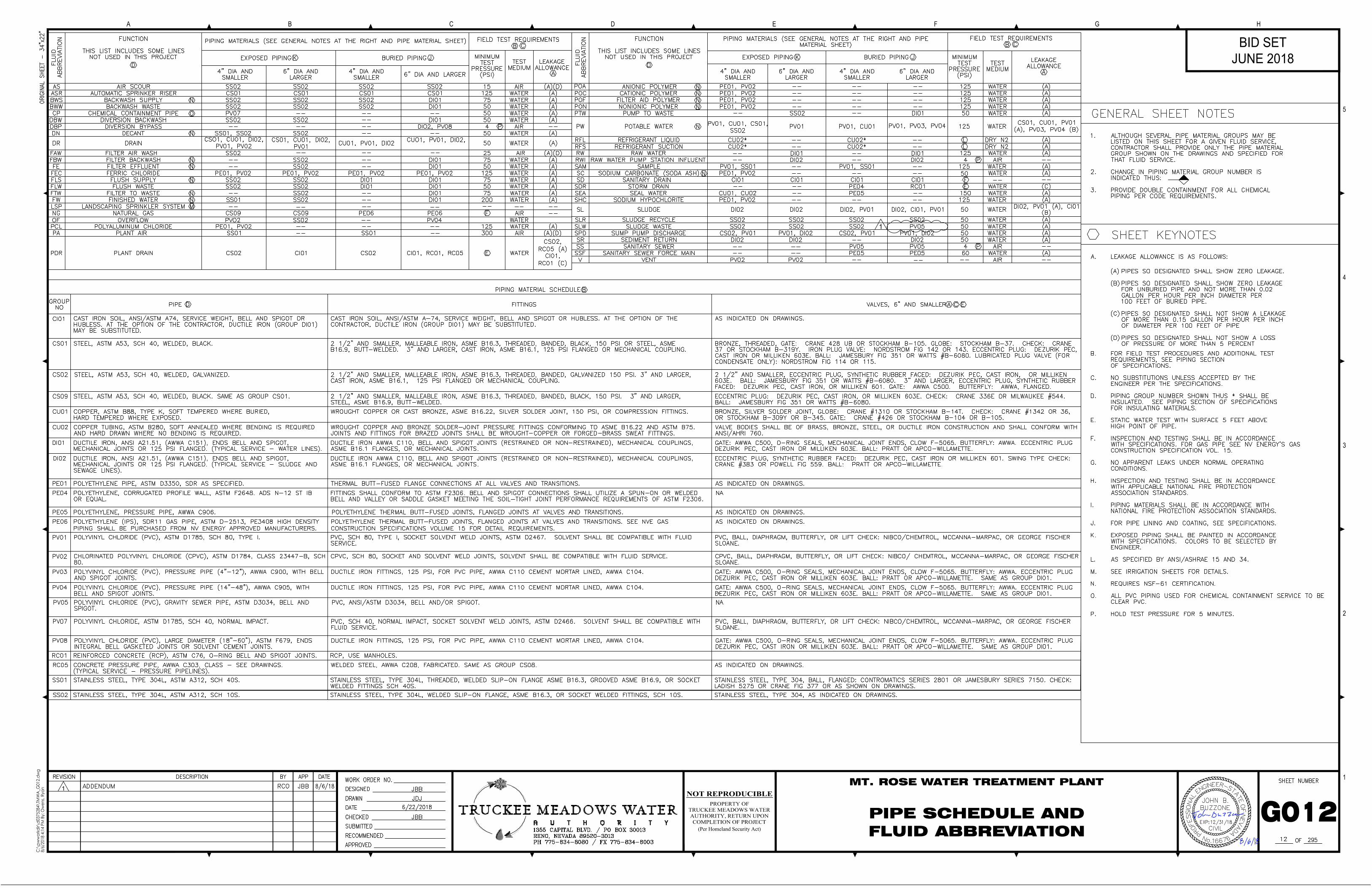
Question No. 4: Reference the pipe schedule on sheet G012. System test pressure requirements are provided in
this schedule, but service pressures are not. Note 1 for detail M803 found on sheet GM07 states that “all
components for piping systems with service pressure class greater than 150 PSI shall be suitable for the higher
pressure.” Currently there is no way to determine what operating pressures will be or if this note is applicable.
Please identify what the maximum service pressure is for all systems. Also, the High Pressure Butterfly Valves
are called out to have a bolt pattern of ANSI Class 300 flanges in spec section 15202 (which would be per ANSI/
ASME B16.1 Class 250). If maximum service pressures are under 250 psi, can the Butterfly Valve bolt pattern be
in accordance with ANSI/ ASMA B16.1 Class 125, which is rated for 250 psi?
Response to Question No. 4
All components shall be suitable for the test pressures indicated.
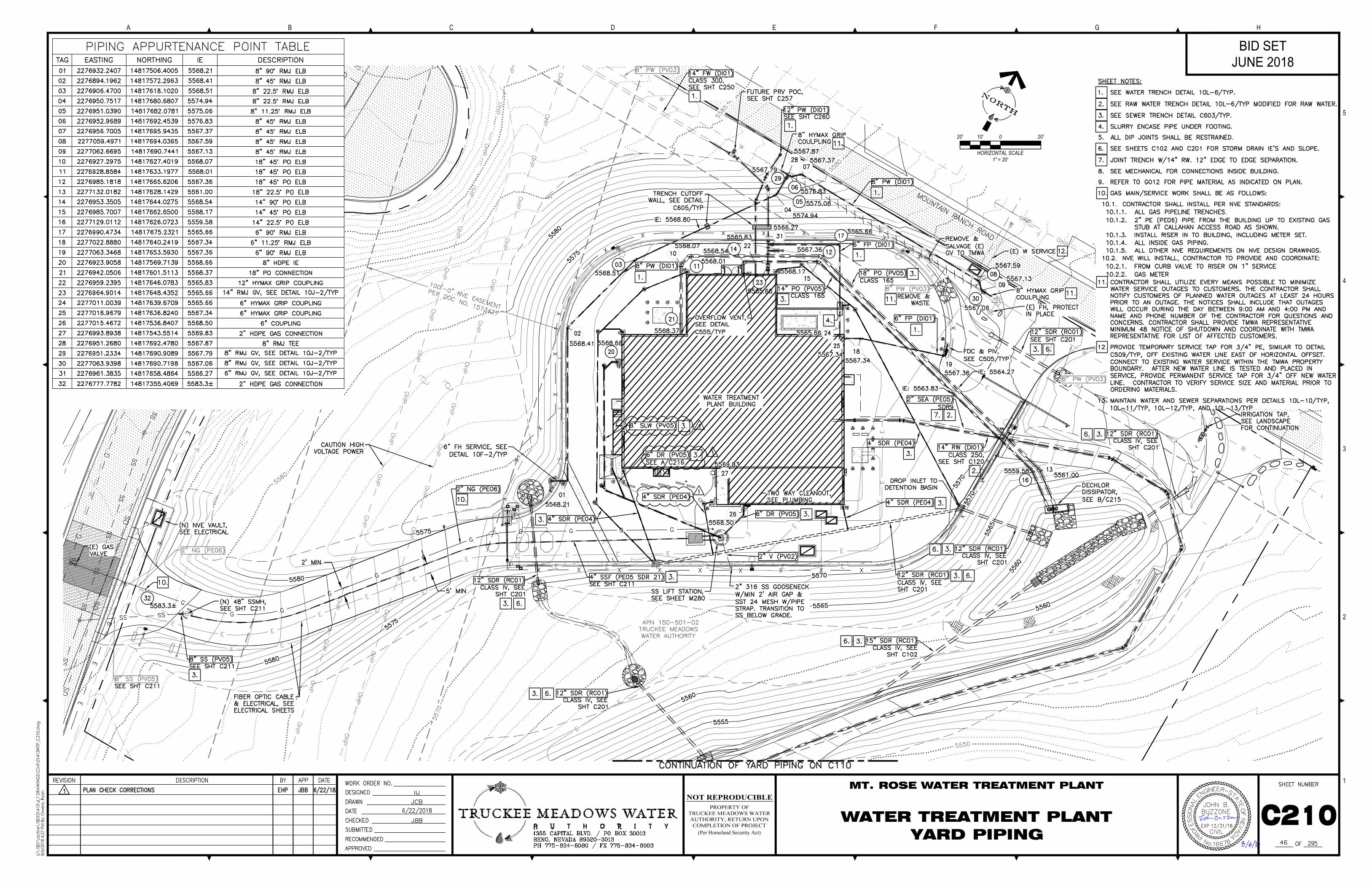
Question No. 5: Sheet C210 (Yard Piping) indicates the 8” SLW buried pipe line to be material type PE05. The
pipe schedule on sheet G012 indicates the pipe material for the buried service SLW to be SS02. Please confirm
which pipe material is required for the buried SLW service.
Response to Question No. 5: Pipe material shall be PV05 as indicated on drawing C210.
Question No. 6: Also, sheet M280 indicates the same pipe line to be 8” SWL. Please confirm the correct
designation for this 8” pipe service.
Response to Question No. 6: The correct pipe designation is “8” SLW”.
Question No. 7: Reference specification section 15030 for Stainless Steel Pipe. 1.2 D states that welders are to
be NSF 61 certified. The National Sanitation Foundation does not certify people. Typically certifications are
provided for the materials used to confirm compliance with the NSF 61 standard. Please confirm only Stainless
Steel Pipe materials will need to be NSF 61 certified, not individuals.
Response to Question No. 7: Stainless Steel Pipe materials and fabricators will need to be NSF 61 certified. See
modification to specification 15030 as described below in Specifications Section.
DRAWINGS
Drawing No. G012: Delete G012 and replace with attached G012.
Drawing No. C210: Delete C210 and replace with attached C210.
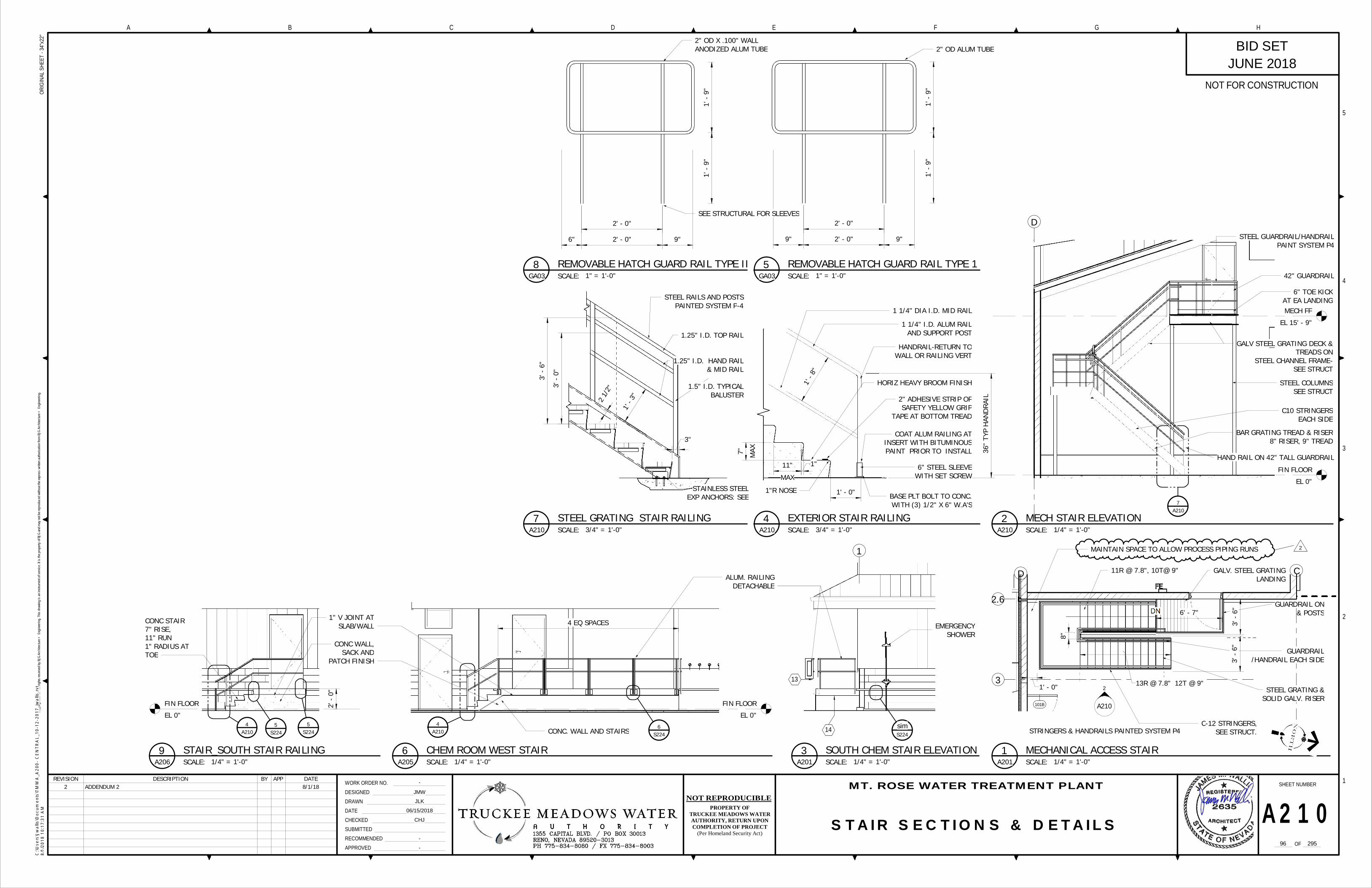
Drawing No. A210: Delete A210 and replace with attached A210.
Drawing No. M120: Delete M120 and replace with attached M120.
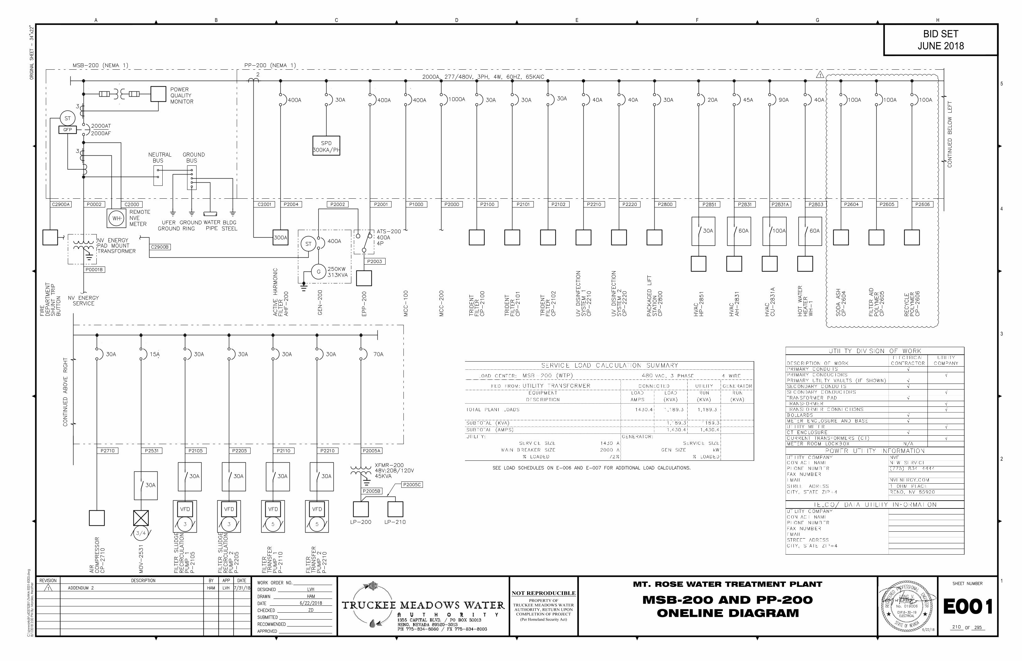
Drawing No. E001: Delete E001 and replace with attachedE001.
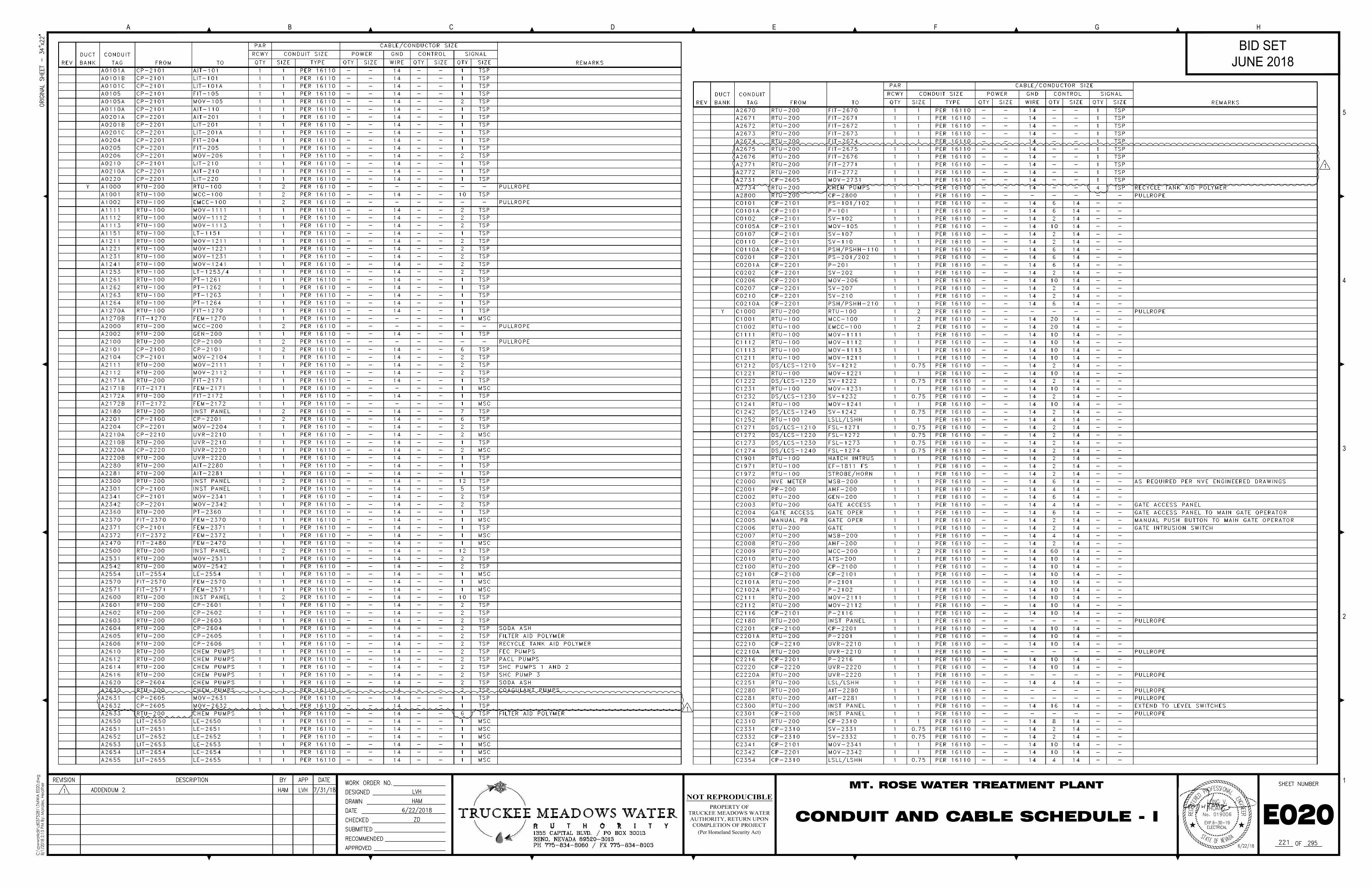
Drawing No. E020: Delete E020 and replace with attached E020.
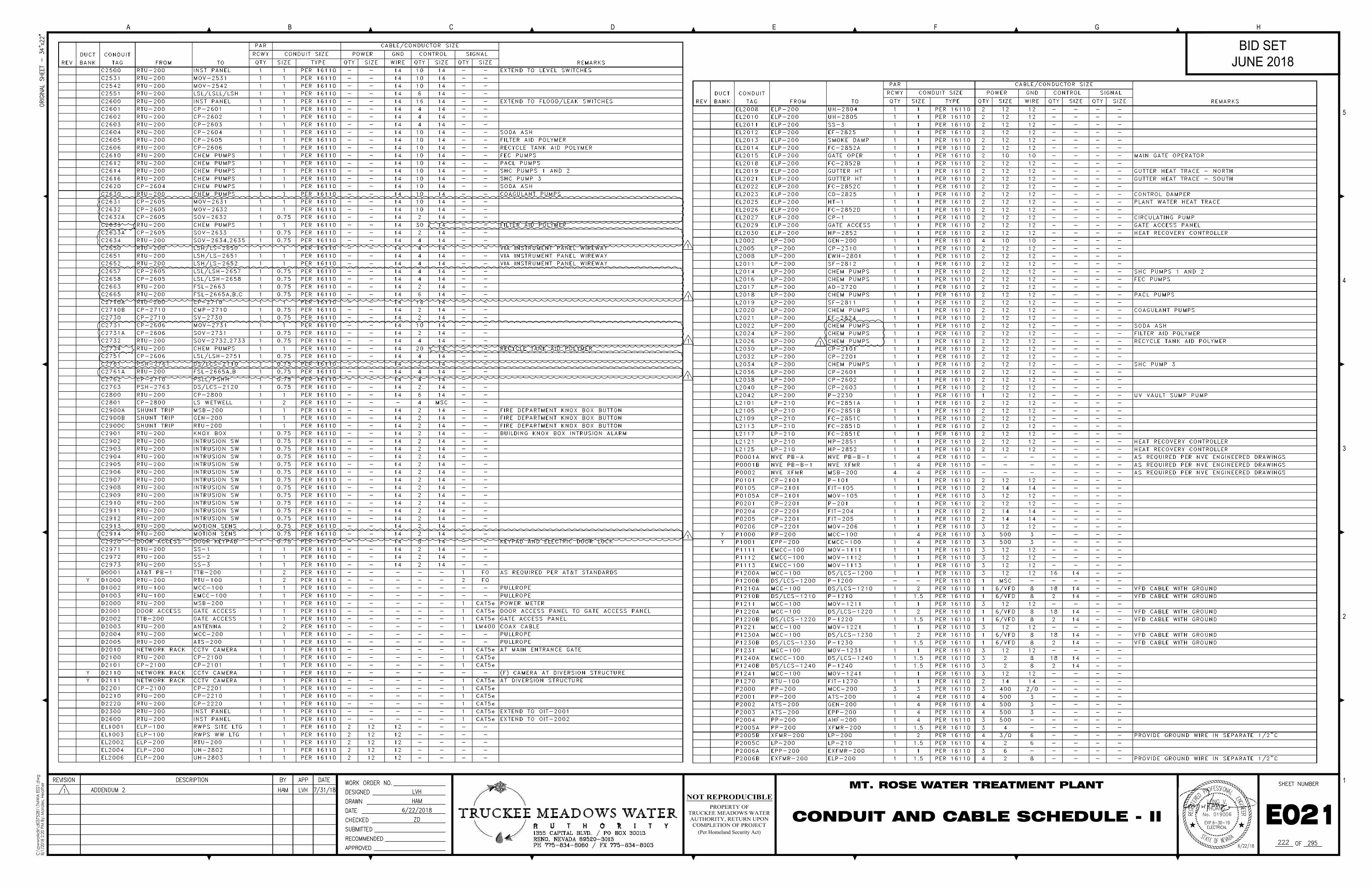
Drawing No. E021: Delete E021 and replace with attached E021.
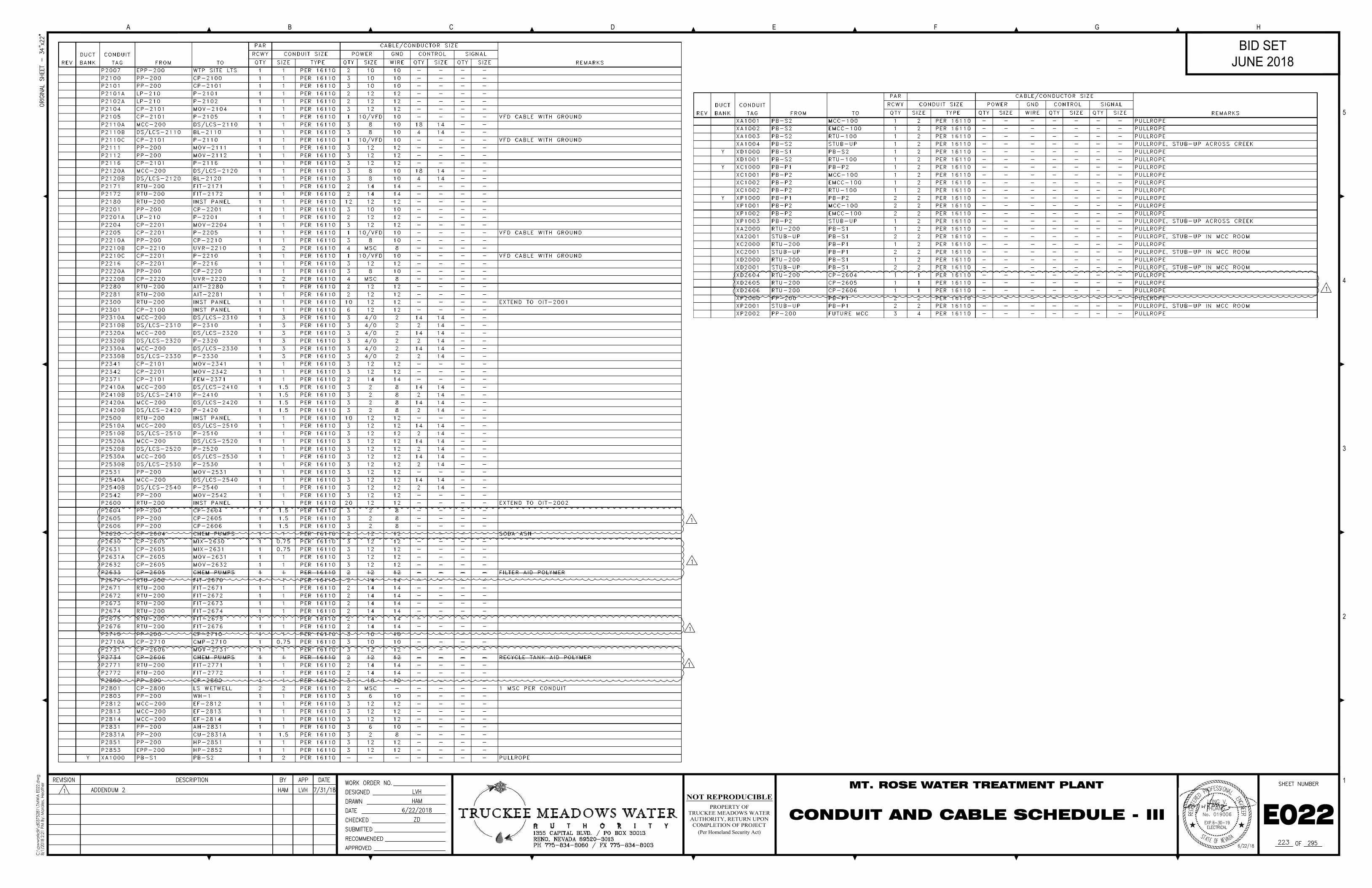
Drawing No. E022: Delete E022 and replace with attached E022.
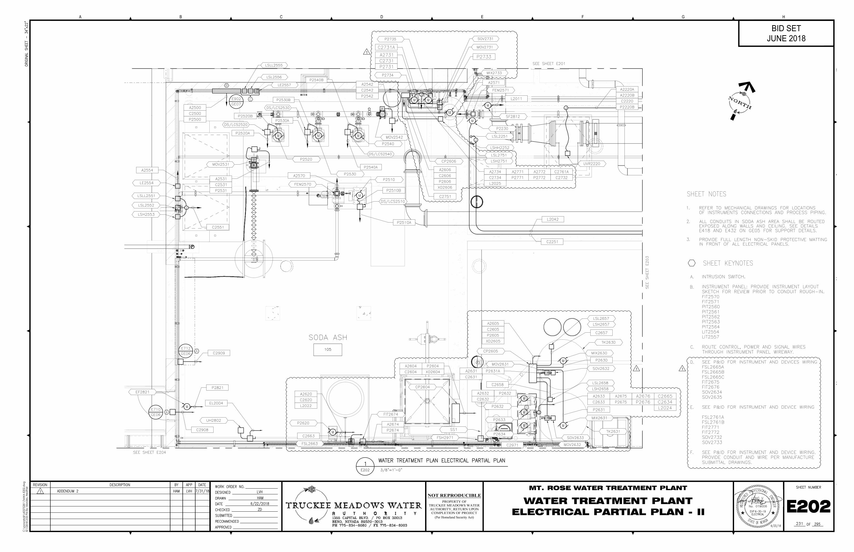
Drawing No. E202: Delete E202 and replace with attached E202.
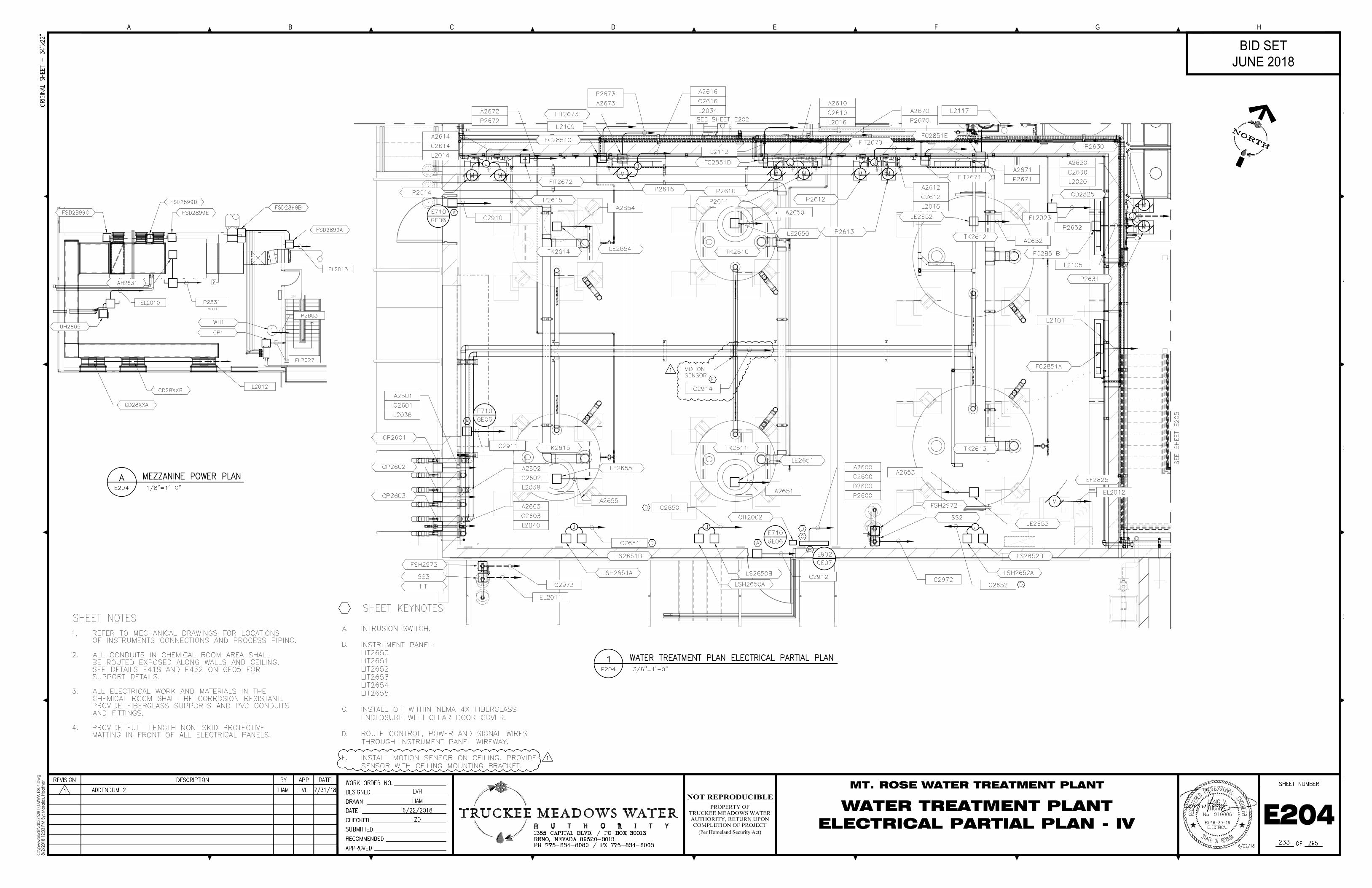
Drawing No. E204: Delete E204 and replace with attached E204.
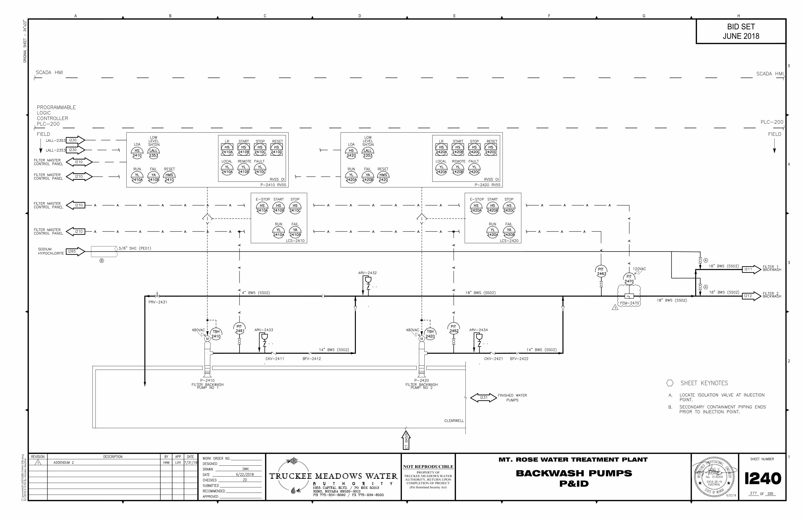
Drawing No. I240: Delete I240 and replace with attached I240.
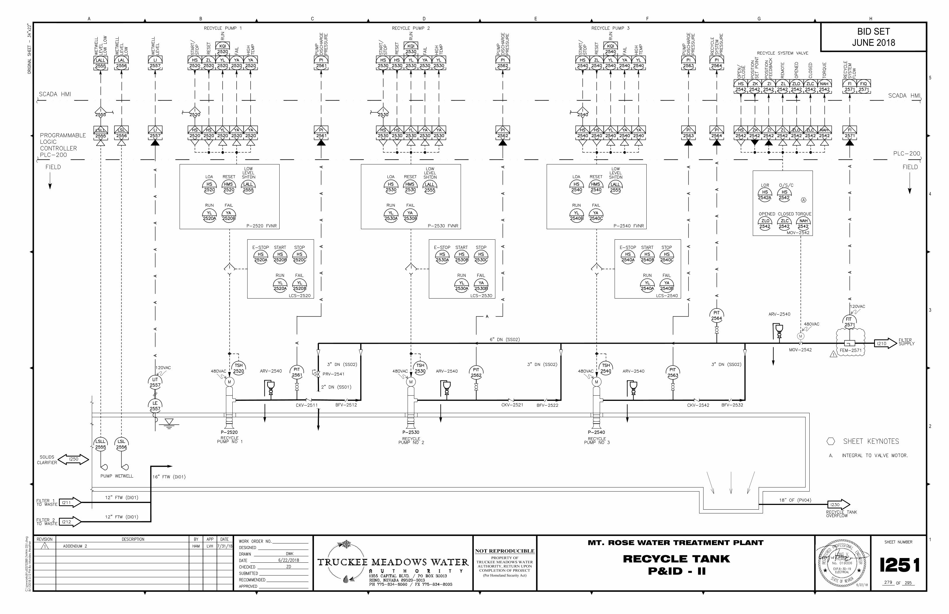
Drawing No. I251: Delete I251 and replace with attached I251.
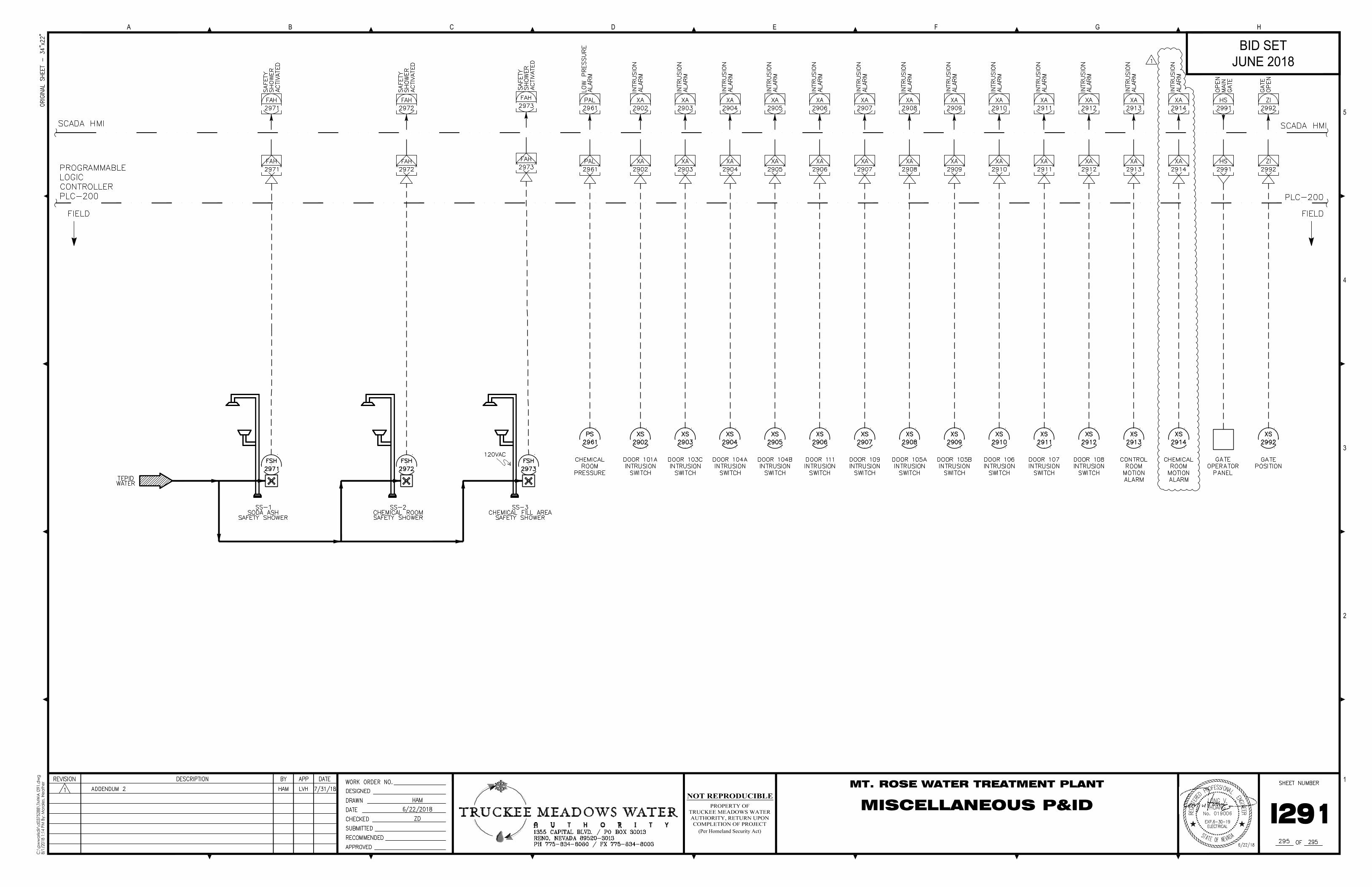
Drawing No. I291: Delete I291 and replace with attached I291.
SPECIFICATIONS
Technical Specifications Table of Contents: Delete: Technical Specifications Table of Contents.
Replace with attached Technical Specifications Table of Contents.
Specification No. 00700: Delete Article 5 of the General Conditions in entirety and replace with the
attached.
Specification No. 00800: Delete Specification 00800 and replace with attached Specification 00800.
Specification No. 15000:
Delete: “15000 2.2.E.1 Unless otherwise shown on the drawings, or indicated in the applicable Sections,
Bolts and nuts shall conform to the following requirements;”
Replace with: “15000 2.2.E.1 Unless otherwise shown on the drawings, or indicated elsewhere in this
Section, Bolts and nuts shall conform to the following requirements;”
Delete: “15000 2.2.E.
2. Fastener Material Group Numbering System
a. Flange fasteners shall conform to the following material standards and shall be
categorized within the Fastener Material Schedule Groups as indicated:
1) Material Group C1 (Carbon steel): ASTM A307 Grade A bolts, ASTM A563
Grade A nuts with ASTM F436 washers
2) Material Group S1 (316 SS): ASTM A193, Grade B8M bolts, ASTM A194
Grade 8M nuts with Type 316 SS plain washers.
3) Material Group S2 (304 SS): ASTM A193, Grade B8 bolts, ASTM A194
Grade 8F nuts with Type 304 SS plain washers.
4) Material Group S3 (Hastelloy C-276): ASTM F468 N10276 bolts ASTM
F467 N10276 nuts with type Hastelloy plain washers.
Replace: “15000 2.2.E.
2. Fastener Material Group Numbering System
a. Flange fasteners shall conform to the following material standards and shall be
categorized within the Fastener Material Schedule Groups as indicated:
1) Material Group C1 (Carbon steel): ASTM A307 Grade A bolts, ASTM A563
Grade A nuts with ASTM F436 washers
2) Material Group C2 (Carbon steel): ASTM A193 Grade B7 bolts, ASTM
A194 Grade 2H nuts with ASTM F436 washers
3) Material Group S1 (316 SS): ASTM A193, Grade B8M bolts, ASTM A194
Grade 8M nuts with Type 316 SS plain washers.
4) Material Group S2 (304 SS): ASTM A193, Grade B8 bolts, ASTM A194
Grade 8F nuts with Type 304 SS plain washers.
5) Material Group S3 (Hastelloy C-276): ASTM F468 N10276 bolts ASTM
F467 N10276 nuts with type Hastelloy plain washers.”
Specification No. 15030:
Delete: “15030 1.2.D Provide written NSF 61 certification for welders who are to weld stainless steel
piping in potable water service.”
Replace with: “15030 1.2.D Provide NSF 61 certification for fabricators providing stainless steel piping
in potable water service.”
Specification No. 16460: Delete Specification 16460 and replace with attached Specification 16460.
Specification No. 16480: Delete Specification 16480 and replace with attached Specification 16480.
Specification No. 16485: Delete Specification 16485 and replace with attached Specification 16485.
Specification No. 16750: Delete Specification 16750 and replace with attached Specification 16750.

Specification No. 17102: Delete Specification 17102 and replace with attached Specification 17102.
Specification No. 17103: Delete Specification 17103 and replace with attached Specification 17103.
Specification No. 17106: Delete Specification 17106 and replace with attached Specification 17106.
Specification No. 17107: Delete Specification 17107 and replace with attached Specification 17107.
Specification No. 17108: Delete Specification 17108 and replace with attached Specification 17108.
Specification No. 17109: Delete Specification 17109 and replace with attached Specification 17109.
Specification No. 17110: Add attached specification section 17110 Temperature Measuring Systems.
Specification No. 17111: Add attached specification section 17111 Temperature Detection Switches.
Specification No. 17112: Delete Specification 17112 and replace with attached Specification 17112.
Specification No. 17200: Delete Specification 17200 and replace with attached Specification 17200.
QUESTION CUT-OFF DATE: August 23rd, 2018
END OF ADDENDUM NO. 2
REVISED BID SCHEDULES DATED 8/7/18 (Cont)
Master Form Invitation to Bid.rev 9.4.13 Page5
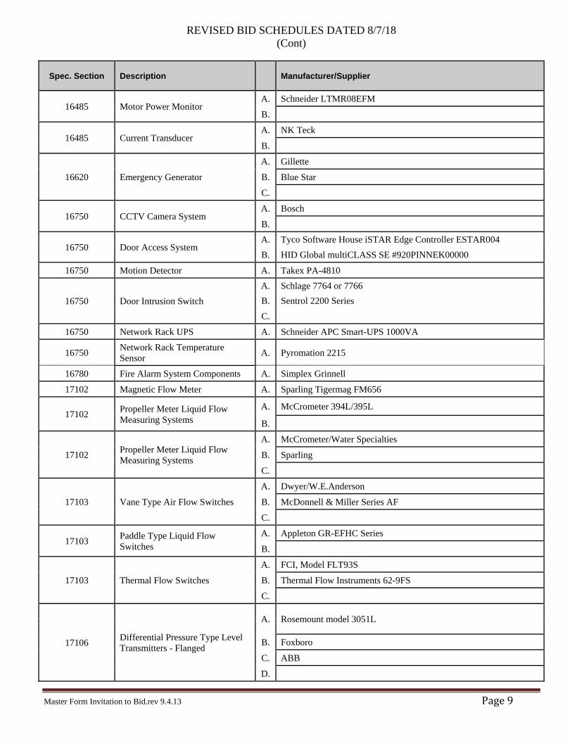
LIST OF EQUIPMENT MANUFACTURERS
Bidder shall list the manufacturer or supplier that will furnish the respective item of equipment. Bidder shall list only one manufacturer or supplier for each piece of equipment listed. Failure by Bidder to list names of manufacturers or suppliers for every item of equipment listed may be cause for rejection of the Bid. The manufacturers or suppliers listed by the Bidder shall not be changed after submitting list unless approved in writing by the Owner.
1.1 LUMP SUM BASE BID
A. The Bidder shall base the Lump Sum Base Bid upon the specified and named Alternate A, B, C, or D major equipment items as listed in the following Major Product or System Schedule.
B. Award of the contract will be made as described in the Instructions to Bidders.
1.2 MAJOR PRODUCT OR SYSTEMS SCHEDULE
A. This section includes a schedule listing alternate equipment acceptable to Owner. The Bidder shall indicate (circle proposed manufacturer) which named alternate equipment it intends to provide. Bidders may also propose “or-equal” equipment for those items where a blank space is provided by writing in the manufacturer’s name. If no blank space is provided, alternate equipment may not be proposed.
B. If an “or equal” manufacturer is proposed by the Bidder, the cost of any required engineering redesign, and the cost of any electrical, mechanical or structural modifications to adjacent and interfacing equipment necessary to make the several parts fit together, licensing fees and additional construction and other costs resulting from the proposed “or equal” equipment shall be included in the Bid. If there is a deviation from the drawings, submittal of new contract drawings requires approval prior to installation; all drawings must be stamped by a Nevada certified professional engineer. These deviations shall be at no cost to the owner. If the proposed “or-equal” manufacturer is not accepted by the Owner after the Award of Contract, the Bidder shall furnish and install the named equipment at no additional cost to the Owner.
C. When an “or-equal” manufacturer is offered by Bidder, the Bidder shall list only such equipment that will comply with the requirements of the Specifications. Equipment will generally be deemed “or equal” provided that the equipment is the same or better than the named equipment in function, performance, reliability, quality, and general configuration.
D. In order that Owner may determine if the proposed “or equal” equipment is a satisfactory alternative to the named equipment, Bidder shall submit full descriptive material and a detailed list of the equipment proposed as outlined in the Instructions to Bidder. No evaluation of submittals will be made prior to the Bid opening. It is the responsibility of Contractor to furnish materials and equipment meeting the requirements of the Specifications, and acceptance of the Bid does not constitute or imply approval of equipment proposed. Owner reserves the right to deny approval of any equipment or materials that do not comply with the Specifications, even though listed herein.
REVISED BID SCHEDULES DATED 8/7/18 (Cont)
Master Form Invitation to Bid.rev 9.4.13 Page6
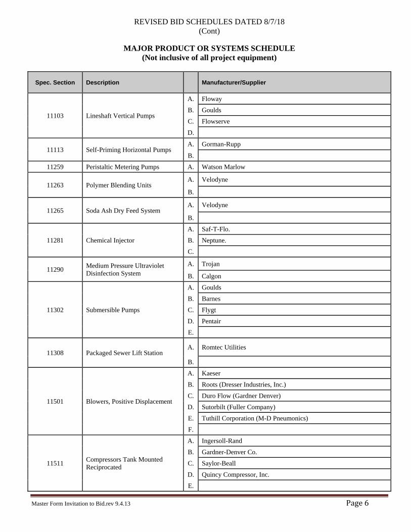
MAJOR PRODUCT OR SYSTEMS SCHEDULE (Not inclusive of all project equipment)
Spec. Section Description
Manufacturer/Supplier
11103 Lineshaft Vertical Pumps
A. Floway
B. Goulds
C. Flowserve
D.
11113 Self-Priming Horizontal Pumps A. Gorman-Rupp
B. 11259 Peristaltic Metering Pumps A. Watson Marlow
11263 Polymer Blending Units A. Velodyne
B.
11265 Soda Ash Dry Feed System A. Velodyne
B.
11281 Chemical Injector
A. Saf-T-Flo.
B. Neptune.
C.
11290 Medium Pressure Ultraviolet Disinfection System
A. Trojan
B. Calgon
11302 Submersible Pumps
A. Goulds
B. Barnes
C. Flygt
D. Pentair
E.
11308 Packaged Sewer Lift Station A. Romtec Utilities
B.
11501 Blowers, Positive Displacement
A. Kaeser
B. Roots (Dresser Industries, Inc.)
C. Duro Flow (Gardner Denver)
D. Sutorbilt (Fuller Company)
E. Tuthill Corporation (M-D Pneumonics)
F.
11511 Compressors Tank Mounted Reciprocated
A. Ingersoll-Rand
B. Gardner-Denver Co.
C. Saylor-Beall
D. Quincy Compressor, Inc.
E.
REVISED BID SCHEDULES DATED 8/7/18 (Cont)
Master Form Invitation to Bid.rev 9.4.13 Page7
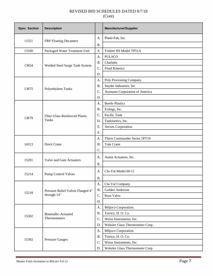
Spec. Section Description
Manufacturer/Supplier
11551 FRP Floating Decanters A. Plasti-Fab, Inc.
B. 13160 Packaged Water Treatment Unit A. Trident HS Model TP51A
13654 Welded Steel Surge Tank System
A. PULSCO
B. Charlatte
C. Fluid Kinetics
D.
13675 Polyethylene Tanks
A. Poly Processing Company
B. Snyder Industries, Inc
C. Assmann Corporation of America
D.
13679 Fiber Glass Reinforced Plastic Tanks
A. Beetle Plastics
B. Ershigs, Inc.
C. Pacific Tank
D. Tankinetics, Inc.
E. Xerxes Corporation
F.
14313 Davit Crane
A. Thern Commander Series 5PT10
B. Yale Crane
C.
15201 Valve and Gate Actuators A. Auma Actuators, Inc.
B.
15214 Pump Control Valves A. Cla-Val Model 60-11
B.
15218 Pressure Relief Valves Flanged 4" through 14"
A. Cla-Val Company
B. Golden Anderson
C. Ross Valve
D.
15302 Bimetallic-Actuated Thermometers
A. Miljoco Corporation.
B. Trerice, H. O. Co.
C. Weiss Instruments, Inc.
D. Weksler Glass Thermometer Corp.
15302 Pressure Gauges
A. Miljoco Corporation.
B. Trerice, H. O. Co.
C. Weiss Instruments, Inc.
D. Weksler Glass Thermometer Corp
REVISED BID SCHEDULES DATED 8/7/18 (Cont)
Master Form Invitation to Bid.rev 9.4.13 Page8
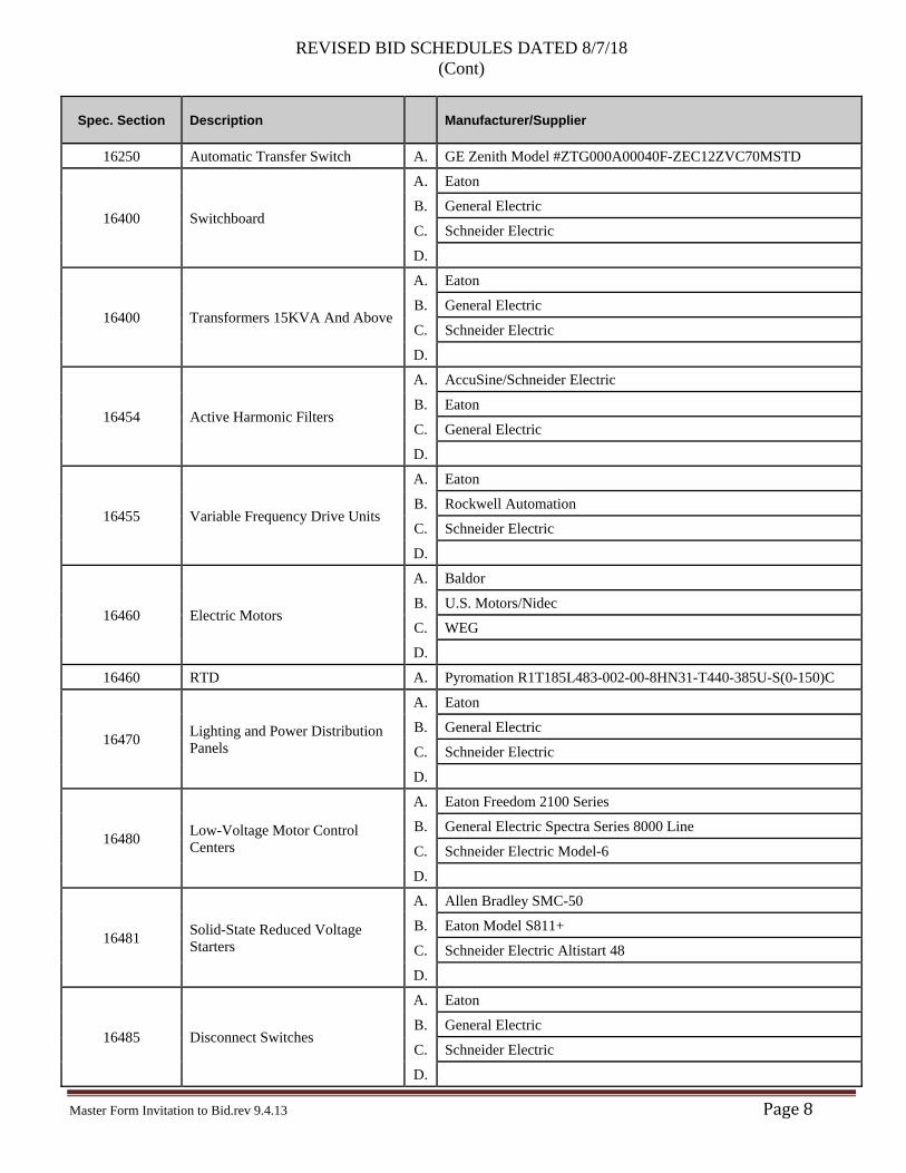
Spec. Section Description
Manufacturer/Supplier
16250 Automatic Transfer Switch A. GE Zenith Model #ZTG000A00040F-ZEC12ZVC70MSTD
16400 Switchboard
A. Eaton
B. General Electric
C. Schneider Electric
D.
16400 Transformers 15KVA And Above
A. Eaton
B. General Electric
C. Schneider Electric
D.
16454 Active Harmonic Filters
A. AccuSine/Schneider Electric
B. Eaton
C. General Electric
D.
16455 Variable Frequency Drive Units
A. Eaton
B. Rockwell Automation
C. Schneider Electric
D.
16460 Electric Motors
A. Baldor
B. U.S. Motors/Nidec
C. WEG
D. 16460 RTD A. Pyromation R1T185L483-002-00-8HN31-T440-385U-S(0-150)C
16470 Lighting and Power Distribution Panels
A. Eaton
B. General Electric
C. Schneider Electric
D.
16480 Low-Voltage Motor Control Centers
A. Eaton Freedom 2100 Series
B. General Electric Spectra Series 8000 Line
C. Schneider Electric Model-6
D.
16481 Solid-State Reduced Voltage Starters
A. Allen Bradley SMC-50
B. Eaton Model S811+
C. Schneider Electric Altistart 48
D.
16485 Disconnect Switches
A. Eaton
B. General Electric
C. Schneider Electric
D.
REVISED BID SCHEDULES DATED 8/7/18 (Cont)
Master Form Invitation to Bid.rev 9.4.13 Page9
Spec. Section Description
Manufacturer/Supplier
16485 Motor Power Monitor A. Schneider LTMR08EFM
B.
16485 Current Transducer A. NK Teck
B.
16620 Emergency Generator
A. Gillette
B. Blue Star
C.
16750 CCTV Camera System A. Bosch
B.
16750 Door Access System A. Tyco Software House iSTAR Edge Controller ESTAR004 B. HID Global multiCLASS SE #920PINNEK00000
16750 Motion Detector A. Takex PA-4810
16750 Door Intrusion Switch A. Schlage 7764 or 7766 B. Sentrol 2200 Series C.
16750 Network Rack UPS A. Schneider APC Smart-UPS 1000VA
16750 Network Rack Temperature Sensor A. Pyromation 2215
16780 Fire Alarm System Components A. Simplex Grinnell
17102 Magnetic Flow Meter A. Sparling Tigermag FM656
17102 Propeller Meter Liquid Flow Measuring Systems
A. McCrometer 394L/395L
B.
17102 Propeller Meter Liquid Flow Measuring Systems
A. McCrometer/Water Specialties
B. Sparling
C.
17103 Vane Type Air Flow Switches
A. Dwyer/W.E.Anderson
B. McDonnell & Miller Series AF
C.
17103 Paddle Type Liquid Flow Switches
A. Appleton GR-EFHC Series
B.
17103 Thermal Flow Switches
A. FCI, Model FLT93S
B. Thermal Flow Instruments 62-9FS
C.
17106 Differential Pressure Type Level Transmitters - Flanged
A. Rosemount model 3051L
B. Foxboro
C. ABB
D.
REVISED BID SCHEDULES DATED 8/7/18 (Cont)
Master Form Invitation to Bid.rev 9.4.13 Page10
Spec. Section Description
Manufacturer/Supplier
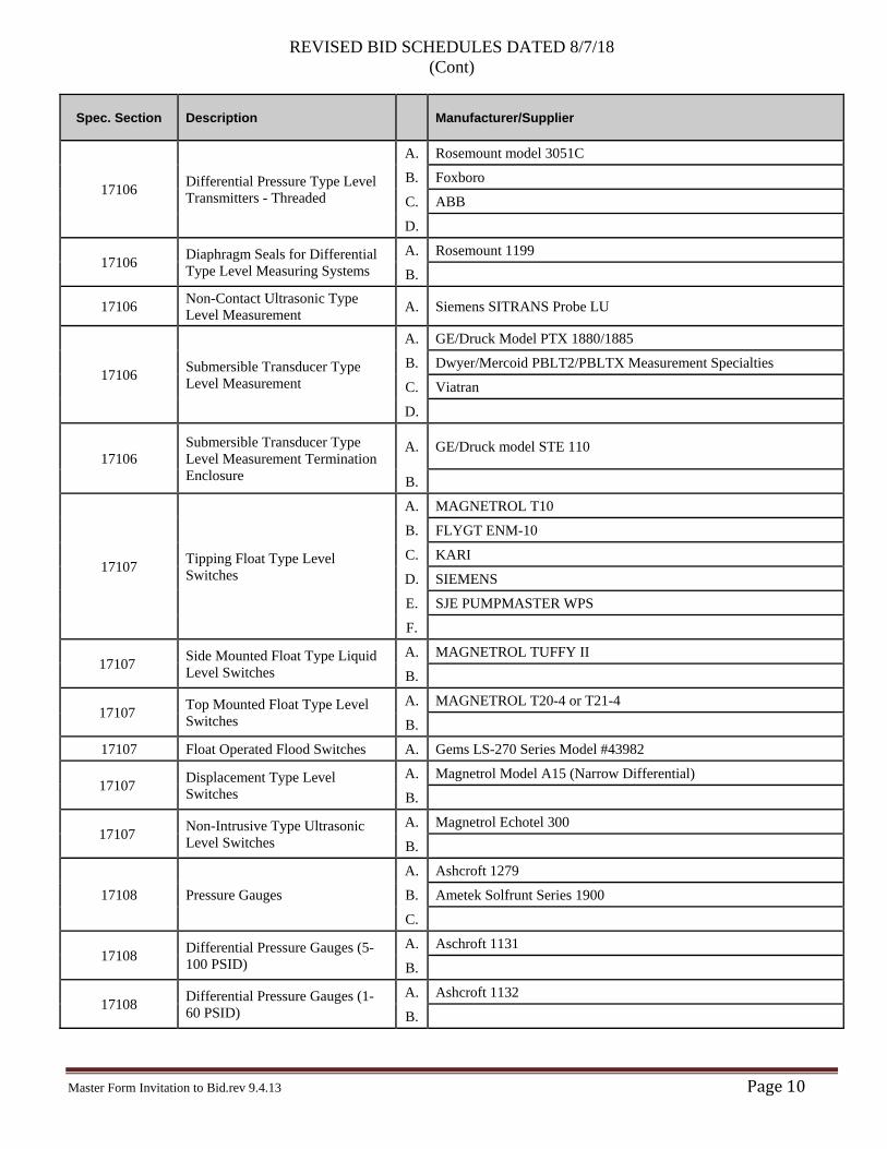
17106 Differential Pressure Type Level Transmitters - Threaded
A. Rosemount model 3051C
B. Foxboro
C. ABB
D.
17106 Diaphragm Seals for Differential Type Level Measuring Systems
A. Rosemount 1199
B.
17106 Non-Contact Ultrasonic Type Level Measurement A. Siemens SITRANS Probe LU
17106 Submersible Transducer Type Level Measurement
A. GE/Druck Model PTX 1880/1885
B. Dwyer/Mercoid PBLT2/PBLTX Measurement Specialties
C. Viatran
D.
17106 Submersible Transducer Type Level Measurement Termination Enclosure
A. GE/Druck model STE 110
B.
17107 Tipping Float Type Level Switches
A. MAGNETROL T10
B. FLYGT ENM-10
C. KARI
D. SIEMENS
E. SJE PUMPMASTER WPS
F.
17107 Side Mounted Float Type Liquid Level Switches
A. MAGNETROL TUFFY II
B.
17107 Top Mounted Float Type Level Switches
A. MAGNETROL T20-4 or T21-4
B. 17107 Float Operated Flood Switches A. Gems LS-270 Series Model #43982
17107 Displacement Type Level Switches
A. Magnetrol Model A15 (Narrow Differential)
B.
17107 Non-Intrusive Type Ultrasonic Level Switches
A. Magnetrol Echotel 300
B.
17108 Pressure Gauges
A. Ashcroft 1279
B. Ametek Solfrunt Series 1900
C.
17108 Differential Pressure Gauges (5-100 PSID)
A. Aschroft 1131
B.
17108 Differential Pressure Gauges (1-60 PSID)
A. Ashcroft 1132
B.
REVISED BID SCHEDULES DATED 8/7/18 (Cont)
Master Form Invitation to Bid.rev 9.4.13 Page11
Spec. Section Description
Manufacturer/Supplier
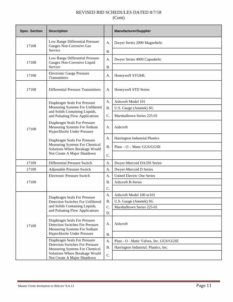
17108 Low Range Differential Pressure Gauges Non-Corrosive Gas Service
A. Dwyer Series 2000 Magnehelic
B.
17108 Low Range Differential Pressure Gauges Non-Corrosive Liquid Service
A. Dwyer Series 4000 Capsuhelic
B.
17108 Electronic Gauge Pressure Transmitters A. Honeywell STG84L
17108 Differential Pressure Transmitters A. Honeywell STD Series
17108
Diaphragm Seals For Pressure Measuring Systems For Unfiltered and Solids Containing Liquids, and Pulsating Flow Applications
A. Ashcroft Model 101
B. U.S. Gauge (Ametek) SG
C. Marshalltown Series 225-01
Diaphragm Seals For Pressure Measuring Systems For Sodium Hypochlorite Under Pressure
A. Ashcroft
Diaphragm Seals For Pressure Measuring Systems For Chemical Solutions Where Breakage Would Not Create A Major Shutdown
A. Harrington Industrial Plastics
B. Plast – O – Matic GGS/GGSE
C.
17109 Differential Pressure Switch A. Dwyer-Mercoid DA/DS Series
17109 Adjustable Pressure Switch A. Dwyer-Mercoid D Series
17109
Electronic Pressure Switch A. United Electric One Series
B. Ashcroft B-Series
C.
17109
Diaphragm Seals For Pressure Detection Switches For Unfiltered and Solids Containing Liquids, and Pulsating Flow Applications
A. Ashcroft Model 100 or101
B. U.S. Gauge (Ametek) SG C. Marshalltown Series 225-01 D.
Diaphragm Seals For Pressure Detection Switches For Pressure Measuring Systems For Sodium Hypochlorite Under Pressure
A. Ashcroft
B. Diaphragm Seals For Pressure Detection Switches For Pressure Measuring Systems For Chemical Solutions Where Breakage Would Not Create A Major Shutdown
A. Plast - O - Matic Valves, Inc. GGS/GGSE
B. Harrington Industrial. Plastics, Inc.
C.
REVISED BID SCHEDULES DATED 8/7/18 (Cont)
Master Form Invitation to Bid.rev 9.4.13 Page12
Spec. Section Description
Manufacturer/Supplier
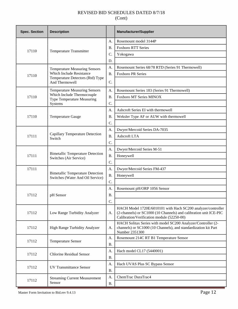
17110 Temperature Transmitter
A. Rosemount model 3144P
B. Foxboro RTT Series
C. Yokogawa
D.
17110
Temperature Measuring Sensors Which Include Resistance Temperature Detectors (Rtd) Type And Thermowell
A. Rosemount Series 68/78 RTD (Series 91 Thermowell)
B. Foxboro PR Series
C.
17110
Temperature Measuring Sensors Which Include Thermocouple Type Temperature Measuring Systems
A. Rosemount Series 183 (Series 91 Thermowell)
B. Foxboro MT Series MINOX
C.
17110 Temperature Gauge
A. Ashcroft Series EI with thermowell
B. Weksler Type AF or AUW with thermowell
C.
17111 Capillary Temperature Detection Switch
A. Dwyer/Mercoid Series DA-7035
B. Ashcroft LTA
C.
17111 Bimetallic Temperature Detection Switches (Air Service)
A. Dwyer/Mercoid Series M-51
B. Honeywell
C. 17111
Bimetallic Temperature Detection Switches (Water And Oil Service)
A. Dwyer/Mercoid Series FM-437 B. Honeywell C.
17112 pH Sensor
A. Rosemount pH/ORP 1056 Sensor
B. C.
17112 Low Range Turbidity Analyzer A. HACH Model 1720E/6010101 with Hach SC200 analyzer/controller (2-channels) or SC1000 (10 Channels) and calibration unit ICE-PIC Calibration/Verification module (52250-00)
17112 High Range Turbidity Analyzer A. HACH Solitax Series with model SC200 Analyzer/Controller (2-channels) or SC1000 (10 Channels), and standardization kit Part Number 2351300
17112 Temperature Sensor A. Rosemount 214C RT B1 Temperature Sensor
B.
17112 Chlorine Residual Sensor A. Hach model CL17 (5440001)
B.
17112 UV Transmittance Sensor A. Hach UVAS Plus SC Bypass Sensor
B.
17112 Streaming Current Measurement Sensor
A. ChemTrac DuraTrac4
B.
REVISED BID SCHEDULES DATED 8/7/18 (Cont)
Master Form Invitation to Bid.rev 9.4.13 Page13
Spec. Section Description
Manufacturer/Supplier
17112 Analyzer/Controller A. Hach SC 1000
B.
17200 Enclosures A Saginaw
B Hoffmann
17200 Terminal Block A. Phoenix Contact
17200 Uninterruptible Power Supply A. Schneider APC Smart-UPS 1000VA
17200 DC Power Supply A. Power Sonic PS 1270
17200 Panel Surge Protector A. Phoenix Contact 2807586
17510 PLC-Based Control System A. Schneider M300 or M500 Series
17510 Operator Interface Terminal A. Schneider Magelis
17510 Ethernet Managed Switches A. Phoenix Contact 2891152 or 2891929
17510 Network Router A. Cisco
B. 17510 Communication Network Bridge A. Multiplexer by Modicon model BM85 (P/N NW-BM85-000)
Notes: 1. Not all major products and systems are included in the table above; only those items related to mechanical equipment. Other products, such as concrete, steel and piping are not included. 2. Items in this table must be circled or completed for the bid.
Bidders are advised that the Owner has made a finding that particular materials, products, things and services are designated by specific brand or trade name in order to match other materials, products, things or services in use or to obtain necessary items available only from one source. By listing a sole-source vendor, Owner has only identified a particular product the supply of which will conform to the Contract. Owner does not warrant in any respect the performance of any designated sole-source vendor. Owner shall not be responsible for, and Contractor shall not be excused for, any failure of a sole-source vendor to supply a conforming product in a timely fashion. Bidders shall refer to individual specification sections for specific requirements.
Contractors, manufacturers or suppliers or materials and equipment may offer an alternative product and request the alternatives to specified products be considered equal, unless the Owner has sole-sourced a product. Inclusion of such alternatives in the bid is the sole responsibility of the Contractor. Inclusion of the proposed alternative should only be considered if it is the Contractor’s sole belief the offered alternative is equal in quality and performance to the specified product. After award of the Contract, such offers of alternative products will be reviewed and processed. If the material, equipment, process or article offered by the Contractor is not, in the Owner’s sole opinion, substantially equal or better in respect to that specified, then the Contractor shall furnish that material, process or article specified or one that in the Owner’s opinion is substantially equal or better in every respect.
BIDDER
(Signature)
(Date)
(Per Homeland Security Act)
PROPERTY OFTRUCKEE MEADOWS WATERAUTHORITY, RETURN UPONCOMPLETION OF PROJECT
NOT REPRODUCIBLEMT. ROSE WATER TREATMENT PLANT
C:\
pww
orkd
ir\d0
3752
84\T
MW
A_G
012.
dwg
8/6/
2018
4:1
4 PM B
y: O
wen
s, Ry
anBID SET
1
2
3
4
5
HGFEDCBA
JUNE 2018
FLUID ABBREVIATIONPIPE SCHEDULE AND G012
1
1
0
HORIZONTAL SCALE1" = 20'
20' 10' 20'
(Per Homeland Security Act)
PROPERTY OFTRUCKEE MEADOWS WATERAUTHORITY, RETURN UPONCOMPLETION OF PROJECT
NOT REPRODUCIBLEMT. ROSE WATER TREATMENT PLANT
U:\1
801\
activ
e\18
0101
413\
6.7
DRAW
ING
S\C
ivil\
0141
3WTP
_C21
0.dw
g8/
6/20
18 4
:27
PM By:
Ow
ens,
Ryan
BID SET
1
2
3
4
5
HGFEDCBA
JUNE 2018
C210WATER TREATMENT PLANTYARD PIPING
FIN FLOOREL 0"
D
MECH FFEL 15' - 9"
GALV STEEL GRATING DECK &TREADS ON
STEEL CHANNEL FRAME-SEE STRUCT
42" GUARDRAIL
BAR GRATING TREAD & RISER8" RISER, 9" TREAD
STEEL COLUMNSSEE STRUCT
C10 STRINGERSEACH SIDE
HAND RAIL ON 42" TALL GUARDRAIL
6" TOE KICKAT EA LANDING
STEEL GUARDRAIL/HANDRAILPAINT SYSTEM P4
A2107
CD
3
8"
GALV. STEEL GRATINGLANDING
GUARDRAIL ON& POSTS
3' -
6"6' - 7"
STEEL GRATING &SOLID GALV. RISER
13R @ 7.8" 12T @ 9"1' - 0"
C-12 STRINGERS,SEE STRUCT.
GUARDRAIL/HANDRAIL EACH SIDE
STRINGERS & HANDRAILS PAINTED SYSTEM P4
2.6
A210
2
11R @ 7.8", 10T@ 9"
3' -
6"
101B
MAINTAIN SPACE TO ALLOW PROCESS PIPING RUNS
FIN FLOOREL 0"
4 EQ SPACES
S2246
ALUM. RAILINGDETACHABLE
A2104
CONC. WALL AND STAIRS S2246
1.25" I.D. TOP RAIL
2 1/2
"
3"
3' -
0"3' -
6" 1.25" I.D. HAND RAIL& MID RAIL
1.5" I.D. TYPICALBALUSTER
STAINLESS STEELEXP ANCHORS: SEE
STEEL RAILS AND POSTSPAINTED SYSTEM P-4
1' - 3
"
FIN FLOOREL 0"
A2104
S2245
S2245
1" V JOINT ATSLAB/WALL
CONC WALL,SACK AND
PATCH FINISH
CONC STAIR7" RISE,11" RUN1" RADIUS ATTOE
2' -
0"
COAT ALUM RAILING ATINSERT WITH BITUMINOUSPAINT PRIOR TO INSTALL
1 1/4" DIA I.D. MID RAIL
BASE PLT BOLT TO CONC.WITH (3) 1/2" X 6" W.A'S
HANDRAIL-RETURN TOWALL OR RAILING VERT
1 1/4" I.D. ALUM RAILAND SUPPORT POST
1' - 0"
1' - 8
"
36" T
YP H
ANDR
AIL
6" STEEL SLEEVEWITH SET SCREWMAX
11" 1"
2" ADHESIVE STRIP OFSAFETY YELLOW GRIP
TAPE AT BOTTOM TREAD
HORIZ HEAVY BROOM FINISH
1"R NOSE
MAX7"
1
13
14 sim
EMERGENCYSHOWER
2' - 0"
9" 2' - 0" 9"
1' -
9"1'
- 9"
2" OD ALUM TUBE
2' - 0"
6" 2' - 0" 9"
1' -
9"1'
- 9"
2" OD X .100" WALLANODIZED ALUM TUBE
SEE STRUCTURAL FOR SLEEVES
SHEET NUMBER
Copy
right
201
6. A
ll rig
hts
rese
rved
by
BJG
Arc
hite
ctur
e +
Eng
inee
ring.
Thi
s dr
awin
g is
an
inst
rum
ent o
f ser
vice
. It i
s th
e pr
oper
ty o
f BJG
and
may
not
be
repr
oduc
ed w
ithou
t the
exp
ress
writ
ten
auth
oriz
atio
n fro
m B
JG A
rchi
tect
ure
+ E
ngin
eerin
g.
A B C D E F G H
5
4
3
2
WORK ORDER NO.
DESIGNED
DRAWN
DATE
CHECKED
SUBMITTED
RECOMMENDED
APPROVED
NOT REPRODUCIBLE
PROPERTY OF
TRUCKEE MEADOWS WATER
AUTHORITY, RETURN UPON
COMPLETION OF PROJECT
(Per Homeland Security Act)
OF
MT. ROSE WATER TREATMENT PLANT
NOT FOR CONSTRUCTION
OR
IGIN
AL
SH
EE
T-
34"x
22"
1
8/1
/20
18
10:1
7:3
1 A
MC
:\Use
rs\J
walli
s\D
ocu
ments
\TM
WA
_A2
00
- C
EN
TR
AL_1
0-1
2-2
017
_jw
allis.
rvt
STAIR SECTIONS & DETAILS A210
BID SET
-
JMW
JLK
CHJ
06/15/2018
-
-96 295
JUNE 2018
SCALE: 1/4" = 1'-0"A2102 MECH STAIR ELEVATION
SCALE: 1/4" = 1'-0"A2011 MECHANICAL ACCESS STAIR
SCALE: 1/4" = 1'-0"A2056 CHEM ROOM WEST STAIR
SCALE: 3/4" = 1'-0"A2107 STEEL GRATING STAIR RAILING
SCALE: 1/4" = 1'-0"A2069 STAIR_SOUTH STAIR RAILING
SCALE: 3/4" = 1'-0"A2104 EXTERIOR STAIR RAILING
SCALE: 1/4" = 1'-0"A2013 SOUTH CHEM STAIR ELEVATION
SCALE: 1" = 1'-0"GA035 REMOVABLE HATCH GUARD RAIL TYPE 1
SCALE: 1" = 1'-0"GA038 REMOVABLE HATCH GUARD RAIL TYPE II
REVISION DESCRIPTION BY APP DATE2 ADDENDUM 2 8/1/18
2
(Per Homeland Security Act)
PROPERTY OFTRUCKEE MEADOWS WATERAUTHORITY, RETURN UPONCOMPLETION OF PROJECT
NOT REPRODUCIBLEMT. ROSE WATER TREATMENT PLANT
U:\1
801\
activ
e\18
0101
413\
6.7
DRAW
ING
S\Pr
oces
s\TM
WA_
M12
0.dw
g8/
6/20
18 3
:15
PM By:
Ow
ens,
Ryan
BID SET
1
2
3
4
5
HGFEDCBA
JUNE 2018
M120RAW WATER PUMP STATIONMECHANICAL PLAN
(Per Homeland Security Act)
PROPERTY OFTRUCKEE MEADOWS WATERAUTHORITY, RETURN UPONCOMPLETION OF PROJECT
NOT REPRODUCIBLEMT. ROSE WATER TREATMENT PLANT
C:\
pww
orkd
ir\d0
3752
81\T
MW
A E0
01-E
003.
dwg
8/1/
2018
2:0
0 PM B
y: M
oral
es, H
eath
erBID SET
1
2
3
4
5
HGFEDCBA
JUNE 2018
MSB-200 AND PP-200ONELINE DIAGRAM E001
(Per Homeland Security Act)
PROPERTY OFTRUCKEE MEADOWS WATERAUTHORITY, RETURN UPONCOMPLETION OF PROJECT
NOT REPRODUCIBLEMT. ROSE WATER TREATMENT PLANT
C:\
pww
orkd
ir\d0
3752
81\T
MW
A E0
20.d
wg
8/1/
2018
2:1
5 PM B
y: M
oral
es, H
eath
erBID SET
1
2
3
4
5
HGFEDCBA
JUNE 2018
CONDUIT AND CABLE SCHEDULE - I E020
(Per Homeland Security Act)
PROPERTY OFTRUCKEE MEADOWS WATERAUTHORITY, RETURN UPONCOMPLETION OF PROJECT
NOT REPRODUCIBLEMT. ROSE WATER TREATMENT PLANT
C:\
pww
orkd
ir\d0
3752
81\T
MW
A E0
21.d
wg
8/1/
2018
2:2
0 PM B
y: M
oral
es, H
eath
erBID SET
1
2
3
4
5
HGFEDCBA
JUNE 2018
CONDUIT AND CABLE SCHEDULE - II E021
(Per Homeland Security Act)
PROPERTY OFTRUCKEE MEADOWS WATERAUTHORITY, RETURN UPONCOMPLETION OF PROJECT
NOT REPRODUCIBLEMT. ROSE WATER TREATMENT PLANT
C:\
pww
orkd
ir\d0
3752
81\T
MW
A E0
22.d
wg
8/1/
2018
2:2
1 PM B
y: M
oral
es, H
eath
erBID SET
1
2
3
4
5
HGFEDCBA
JUNE 2018
CONDUIT AND CABLE SCHEDULE - III E022
(Per Homeland Security Act)
PROPERTY OFTRUCKEE MEADOWS WATERAUTHORITY, RETURN UPONCOMPLETION OF PROJECT
NOT REPRODUCIBLEMT. ROSE WATER TREATMENT PLANT
C:\
pww
orkd
ir\d0
3752
81\T
MW
A E2
02.d
wg
8/1/
2018
2:0
5 PM B
y: M
oral
es, H
eath
erBID SET
1
2
3
4
5
HGFEDCBA
JUNE 2018
WATER TREATMENT PLANTELECTRICAL PARTIAL PLAN - II E202
DN
MECH
(Per Homeland Security Act)
PROPERTY OFTRUCKEE MEADOWS WATERAUTHORITY, RETURN UPONCOMPLETION OF PROJECT
NOT REPRODUCIBLEMT. ROSE WATER TREATMENT PLANT
C:\
pww
orkd
ir\d0
3752
81\T
MW
A E2
04.d
wg
8/2/
2018
12:
33 P
M By:
Mor
ales
, Hea
ther
BID SET
1
2
3
4
5
HGFEDCBA
JUNE 2018
WATER TREATMENT PLANTELECTRICAL PARTIAL PLAN - IV E204
(Per Homeland Security Act)
PROPERTY OFTRUCKEE MEADOWS WATERAUTHORITY, RETURN UPONCOMPLETION OF PROJECT
NOT REPRODUCIBLEMT. ROSE WATER TREATMENT PLANT
C:\
pww
orkd
ir\d0
3752
88\T
MW
A I2
40.d
wg
8/1/
2018
3:1
2 PM B
y: M
oral
es, H
eath
erBID SET
1
2
3
4
5
HGFEDCBA
JUNE 2018
BACKWASH PUMPSP&ID I240
(Per Homeland Security Act)
PROPERTY OFTRUCKEE MEADOWS WATERAUTHORITY, RETURN UPONCOMPLETION OF PROJECT
NOT REPRODUCIBLEMT. ROSE WATER TREATMENT PLANT
C:\
pww
orkd
ir\d0
3752
88\T
MW
A I2
51.d
wg
8/1/
2018
3:1
2 PM B
y: M
oral
es, H
eath
erBID SET
1
2
3
4
5
HGFEDCBA
JUNE 2018
RECYCLE TANKP&ID - II I251
(Per Homeland Security Act)
PROPERTY OFTRUCKEE MEADOWS WATERAUTHORITY, RETURN UPONCOMPLETION OF PROJECT
NOT REPRODUCIBLEMT. ROSE WATER TREATMENT PLANT
C:\
pww
orkd
ir\d0
3752
88\T
MW
A I2
91.d
wg
8/1/
2018
1:1
4 PM B
y: M
oral
es, H
eath
erBID SET
1
2
3
4
5
HGFEDCBA
JUNE 2018
MISCELLANEOUS P&ID I291
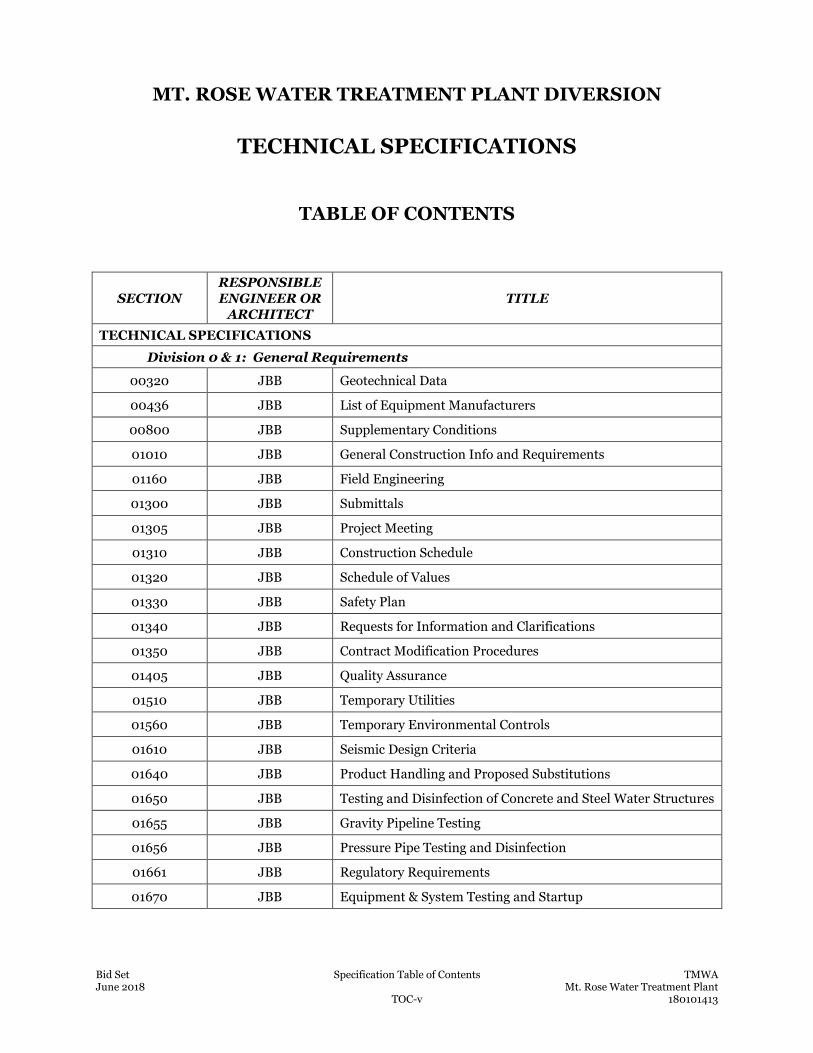
Bid Set Specification Table of Contents TMWA June 2018 Mt. Rose Water Treatment Plant TOC-v 180101413
MT. ROSE WATER TREATMENT PLANT DIVERSION
TECHNICAL SPECIFICATIONS
TABLE OF CONTENTS
SECTION RESPONSIBLE ENGINEER OR
ARCHITECT TITLE
TECHNICAL SPECIFICATIONS
Division 0 & 1: General Requirements
00320 JBB Geotechnical Data
00436 JBB List of Equipment Manufacturers
00800 JBB Supplementary Conditions
01010 JBB General Construction Info and Requirements
01160 JBB Field Engineering
01300 JBB Submittals
01305 JBB Project Meeting
01310 JBB Construction Schedule
01320 JBB Schedule of Values
01330 JBB Safety Plan
01340 JBB Requests for Information and Clarifications
01350 JBB Contract Modification Procedures
01405 JBB Quality Assurance
01510 JBB Temporary Utilities
01560 JBB Temporary Environmental Controls
01610 JBB Seismic Design Criteria
01640 JBB Product Handling and Proposed Substitutions
01650 JBB Testing and Disinfection of Concrete and Steel Water Structures
01655 JBB Gravity Pipeline Testing
01656 JBB Pressure Pipe Testing and Disinfection
01661 JBB Regulatory Requirements
01670 JBB Equipment & System Testing and Startup
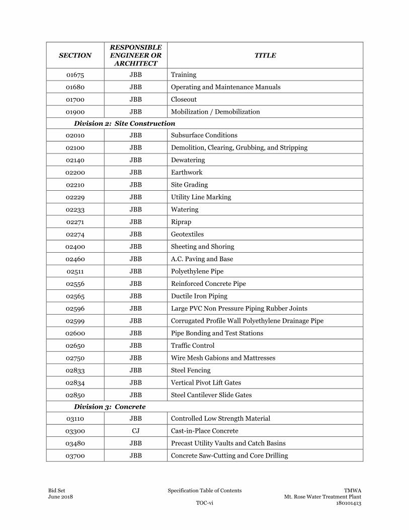
Bid Set Specification Table of Contents TMWA June 2018 Mt. Rose Water Treatment Plant TOC-vi 180101413
SECTION RESPONSIBLE ENGINEER OR
ARCHITECT TITLE
01675 JBB Training
01680 JBB Operating and Maintenance Manuals
01700 JBB Closeout
01900 JBB Mobilization / Demobilization
Division 2: Site Construction
02010 JBB Subsurface Conditions
02100 JBB Demolition, Clearing, Grubbing, and Stripping
02140 JBB Dewatering
02200 JBB Earthwork
02210 JBB Site Grading
02229 JBB Utility Line Marking
02233 JBB Watering
02271 JBB Riprap
02274 JBB Geotextiles
02400 JBB Sheeting and Shoring
02460 JBB A.C. Paving and Base
02511 JBB Polyethylene Pipe
02556 JBB Reinforced Concrete Pipe
02565 JBB Ductile Iron Piping
02596 JBB Large PVC Non Pressure Piping Rubber Joints
02599 JBB Corrugated Profile Wall Polyethylene Drainage Pipe
02600 JBB Pipe Bonding and Test Stations
02650 JBB Traffic Control
02750 JBB Wire Mesh Gabions and Mattresses
02833 JBB Steel Fencing
02834 JBB Vertical Pivot Lift Gates
02850 JBB Steel Cantilever Slide Gates
Division 3: Concrete
03110 JBB Controlled Low Strength Material
03300 CJ Cast-in-Place Concrete
03480 JBB Precast Utility Vaults and Catch Basins
03700 JBB Concrete Saw-Cutting and Core Drilling
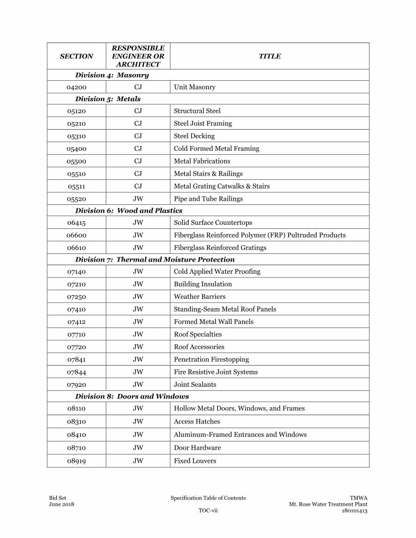
Bid Set Specification Table of Contents TMWA June 2018 Mt. Rose Water Treatment Plant TOC-vii 180101413
SECTION RESPONSIBLE ENGINEER OR
ARCHITECT TITLE
Division 4: Masonry
04200 CJ Unit Masonry
Division 5: Metals
05120 CJ Structural Steel
05210 CJ Steel Joist Framing
05310 CJ Steel Decking
05400 CJ Cold Formed Metal Framing
05500 CJ Metal Fabrications
05510 CJ Metal Stairs & Railings
05511 CJ Metal Grating Catwalks & Stairs
05520 JW Pipe and Tube Railings
Division 6: Wood and Plastics
06415 JW Solid Surface Countertops
06600 JW Fiberglass Reinforced Polymer (FRP) Pultruded Products
06610 JW Fiberglass Reinforced Gratings
Division 7: Thermal and Moisture Protection
07140 JW Cold Applied Water Proofing
07210 JW Building Insulation
07250 JW Weather Barriers
07410 JW Standing-Seam Metal Roof Panels
07412 JW Formed Metal Wall Panels
07710 JW Roof Specialties
07720 JW Roof Accessories
07841 JW Penetration Firestopping
07844 JW Fire Resistive Joint Systems
07920 JW Joint Sealants
Division 8: Doors and Windows
08110 JW Hollow Metal Doors, Windows, and Frames
08310 JW Access Hatches
08410 JW Aluminum-Framed Entrances and Windows
08710 JW Door Hardware
08919 JW Fixed Louvers
Bid Set Specification Table of Contents TMWA June 2018 Mt. Rose Water Treatment Plant TOC-viii 180101413
SECTION RESPONSIBLE ENGINEER OR
ARCHITECT TITLE
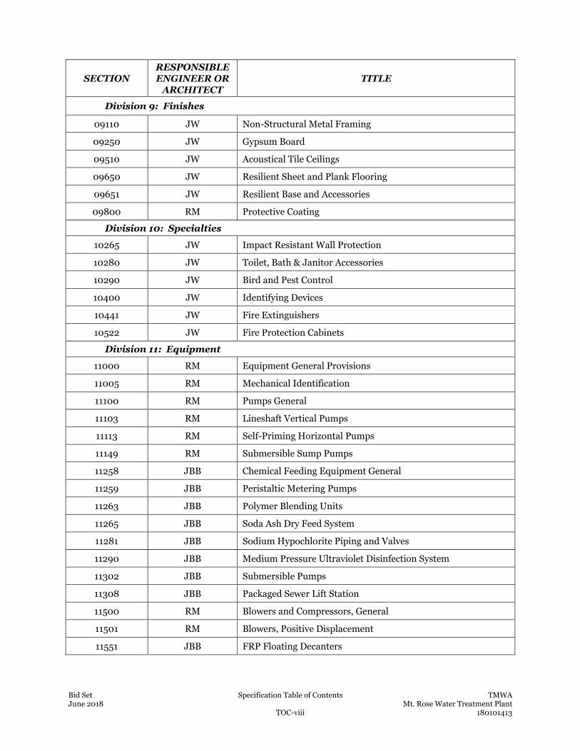
Division 9: Finishes
09110 JW Non-Structural Metal Framing
09250 JW Gypsum Board
09510 JW Acoustical Tile Ceilings
09650 JW Resilient Sheet and Plank Flooring
09651 JW Resilient Base and Accessories
09800 RM Protective Coating
Division 10: Specialties
10265 JW Impact Resistant Wall Protection
10280 JW Toilet, Bath & Janitor Accessories
10290 JW Bird and Pest Control
10400 JW Identifying Devices
10441 JW Fire Extinguishers
10522 JW Fire Protection Cabinets
Division 11: Equipment
11000 RM Equipment General Provisions
11005 RM Mechanical Identification
11100 RM Pumps General
11103 RM Lineshaft Vertical Pumps
11113 RM Self-Priming Horizontal Pumps
11149 RM Submersible Sump Pumps
11258 JBB Chemical Feeding Equipment General
11259 JBB Peristaltic Metering Pumps
11263 JBB Polymer Blending Units
11265 JBB Soda Ash Dry Feed System
11281 JBB Sodium Hypochlorite Piping and Valves
11290 JBB Medium Pressure Ultraviolet Disinfection System
11302 JBB Submersible Pumps
11308 JBB Packaged Sewer Lift Station
11500 RM Blowers and Compressors, General
11501 RM Blowers, Positive Displacement
11551 JBB FRP Floating Decanters
Bid Set Specification Table of Contents TMWA June 2018 Mt. Rose Water Treatment Plant TOC-ix 180101413
SECTION RESPONSIBLE ENGINEER OR
ARCHITECT TITLE
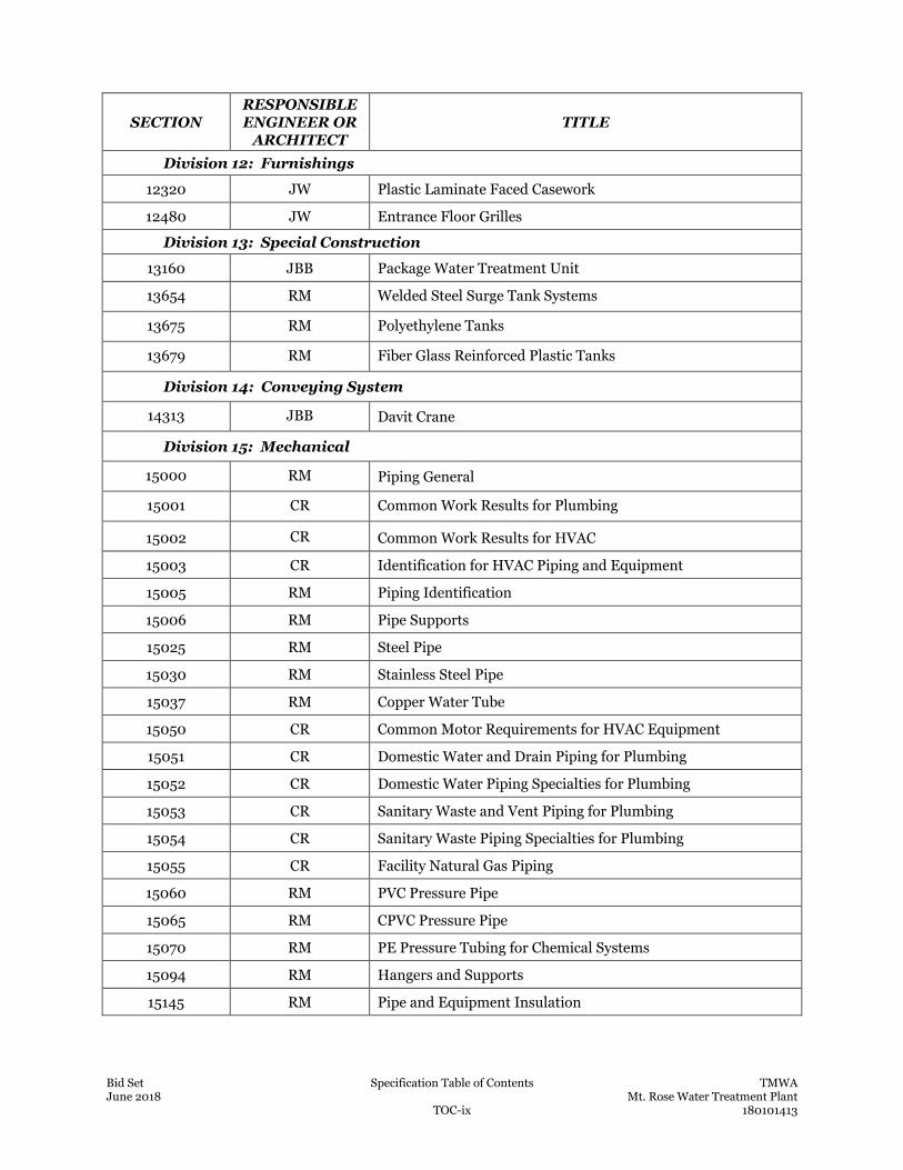
Division 12: Furnishings
12320 JW Plastic Laminate Faced Casework
12480 JW Entrance Floor Grilles
Division 13: Special Construction
13160 JBB Package Water Treatment Unit
13654 RM Welded Steel Surge Tank Systems
13675 RM Polyethylene Tanks
13679 RM Fiber Glass Reinforced Plastic Tanks
Division 14: Conveying System
14313 JBB Davit Crane
Division 15: Mechanical
15000 RM Piping General
15001 CR Common Work Results for Plumbing
15002 CR Common Work Results for HVAC
15003 CR Identification for HVAC Piping and Equipment
15005 RM Piping Identification
15006 RM Pipe Supports
15025 RM Steel Pipe
15030 RM Stainless Steel Pipe
15037 RM Copper Water Tube
15050 CR Common Motor Requirements for HVAC Equipment
15051 CR Domestic Water and Drain Piping for Plumbing
15052 CR Domestic Water Piping Specialties for Plumbing
15053 CR Sanitary Waste and Vent Piping for Plumbing
15054 CR Sanitary Waste Piping Specialties for Plumbing
15055 CR Facility Natural Gas Piping
15060 RM PVC Pressure Pipe
15065 RM CPVC Pressure Pipe
15070 RM PE Pressure Tubing for Chemical Systems
15094 RM Hangers and Supports
15145 RM Pipe and Equipment Insulation
Bid Set Specification Table of Contents TMWA June 2018 Mt. Rose Water Treatment Plant TOC-x 180101413
SECTION RESPONSIBLE ENGINEER OR
ARCHITECT TITLE
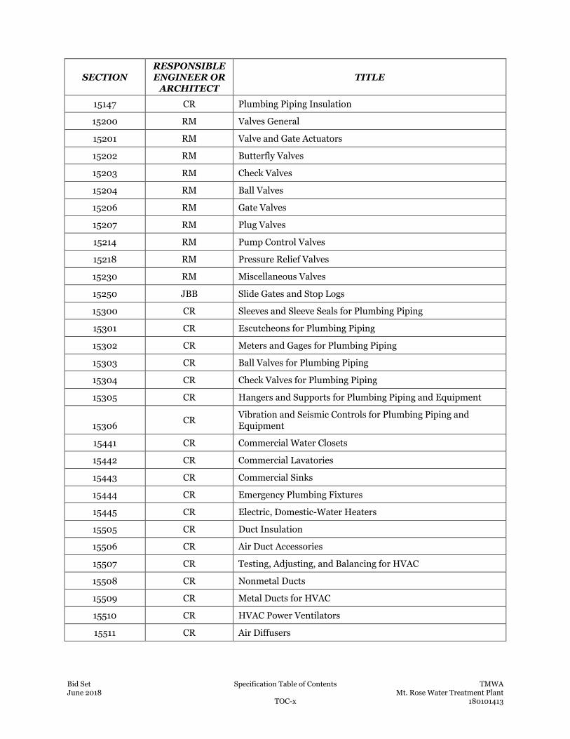
15147 CR Plumbing Piping Insulation
15200 RM Valves General
15201 RM Valve and Gate Actuators
15202 RM Butterfly Valves
15203 RM Check Valves
15204 RM Ball Valves
15206 RM Gate Valves
15207 RM Plug Valves
15214 RM Pump Control Valves
15218 RM Pressure Relief Valves
15230 RM Miscellaneous Valves
15250 JBB Slide Gates and Stop Logs
15300 CR Sleeves and Sleeve Seals for Plumbing Piping
15301 CR Escutcheons for Plumbing Piping
15302 CR Meters and Gages for Plumbing Piping
15303 CR Ball Valves for Plumbing Piping
15304 CR Check Valves for Plumbing Piping
15305 CR Hangers and Supports for Plumbing Piping and Equipment
15306 CR Vibration and Seismic Controls for Plumbing Piping and Equipment
15441 CR Commercial Water Closets
15442 CR Commercial Lavatories
15443 CR Commercial Sinks
15444 CR Emergency Plumbing Fixtures
15445 CR Electric, Domestic-Water Heaters
15505 CR Duct Insulation
15506 CR Air Duct Accessories
15507 CR Testing, Adjusting, and Balancing for HVAC
15508 CR Nonmetal Ducts
15509 CR Metal Ducts for HVAC
15510 CR HVAC Power Ventilators
15511 CR Air Diffusers
Bid Set Specification Table of Contents TMWA June 2018 Mt. Rose Water Treatment Plant TOC-xi 180101413
SECTION RESPONSIBLE ENGINEER OR
ARCHITECT TITLE
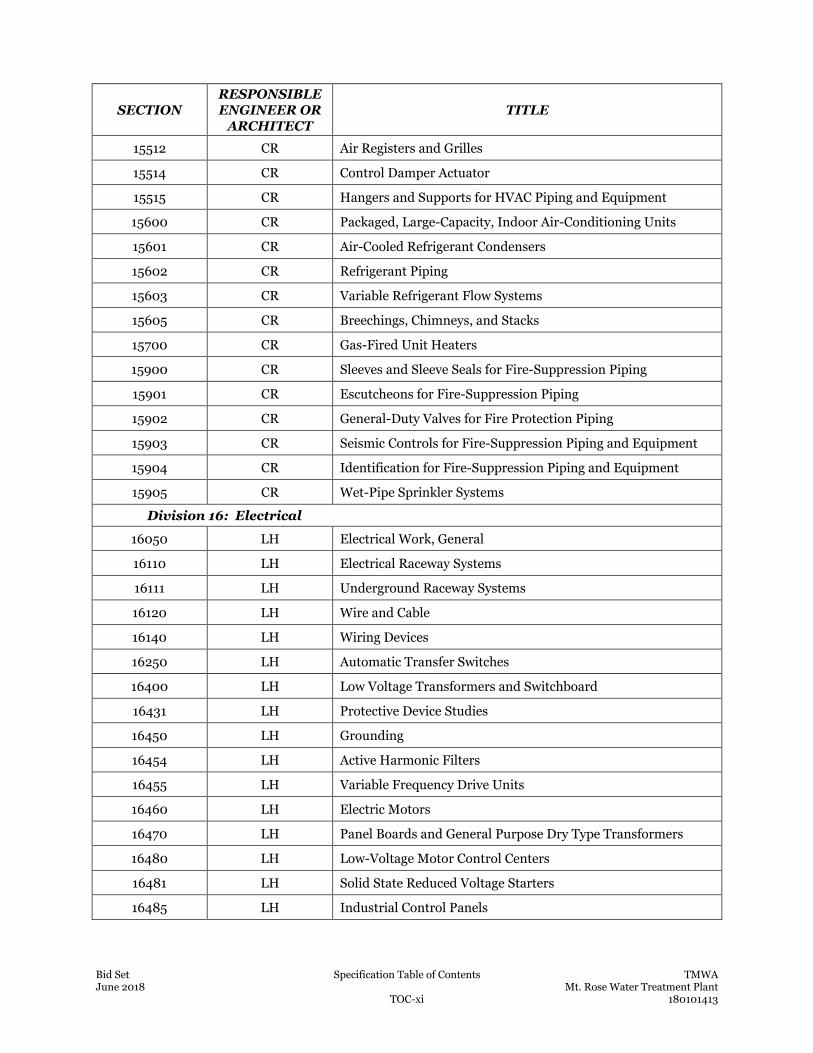
15512 CR Air Registers and Grilles
15514 CR Control Damper Actuator
15515 CR Hangers and Supports for HVAC Piping and Equipment
15600 CR Packaged, Large-Capacity, Indoor Air-Conditioning Units
15601 CR Air-Cooled Refrigerant Condensers
15602 CR Refrigerant Piping
15603 CR Variable Refrigerant Flow Systems
15605 CR Breechings, Chimneys, and Stacks
15700 CR Gas-Fired Unit Heaters
15900 CR Sleeves and Sleeve Seals for Fire-Suppression Piping
15901 CR Escutcheons for Fire-Suppression Piping
15902 CR General-Duty Valves for Fire Protection Piping
15903 CR Seismic Controls for Fire-Suppression Piping and Equipment
15904 CR Identification for Fire-Suppression Piping and Equipment
15905 CR Wet-Pipe Sprinkler Systems
Division 16: Electrical
16050 LH Electrical Work, General
16110 LH Electrical Raceway Systems
16111 LH Underground Raceway Systems
16120 LH Wire and Cable
16140 LH Wiring Devices
16250 LH Automatic Transfer Switches
16400 LH Low Voltage Transformers and Switchboard
16431 LH Protective Device Studies
16450 LH Grounding
16454 LH Active Harmonic Filters
16455 LH Variable Frequency Drive Units
16460 LH Electric Motors
16470 LH Panel Boards and General Purpose Dry Type Transformers
16480 LH Low-Voltage Motor Control Centers
16481 LH Solid State Reduced Voltage Starters
16485 LH Industrial Control Panels
Bid Set Specification Table of Contents TMWA June 2018 Mt. Rose Water Treatment Plant TOC-xii 180101413
SECTION RESPONSIBLE ENGINEER OR
ARCHITECT TITLE
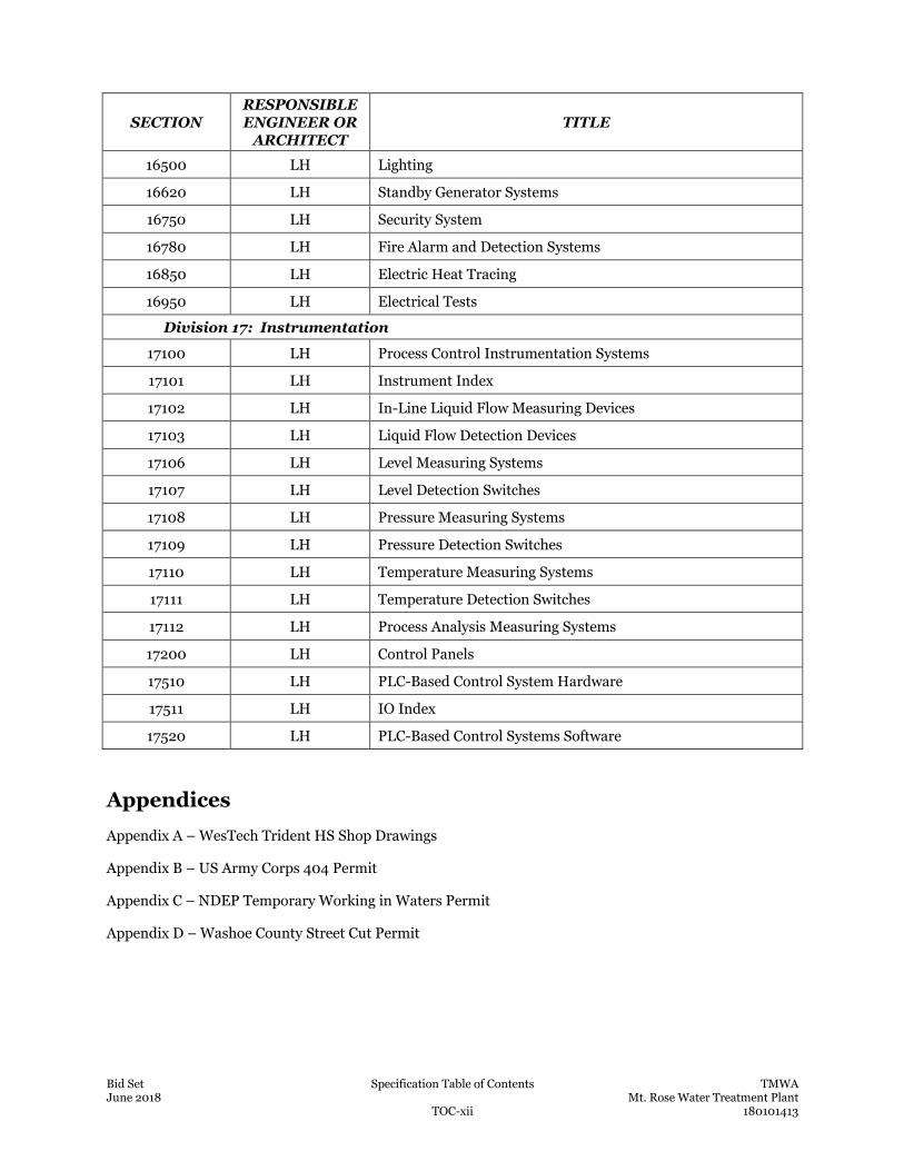
16500 LH Lighting
16620 LH Standby Generator Systems
16750 LH Security System
16780 LH Fire Alarm and Detection Systems
16850 LH Electric Heat Tracing
16950 LH Electrical Tests
Division 17: Instrumentation
17100 LH Process Control Instrumentation Systems
17101 LH Instrument Index
17102 LH In-Line Liquid Flow Measuring Devices
17103 LH Liquid Flow Detection Devices
17106 LH Level Measuring Systems
17107 LH Level Detection Switches
17108 LH Pressure Measuring Systems
17109 LH Pressure Detection Switches
17110 LH Temperature Measuring Systems
17111 LH Temperature Detection Switches
17112 LH Process Analysis Measuring Systems
17200 LH Control Panels
17510 LH PLC-Based Control System Hardware
17511 LH IO Index
17520 LH PLC-Based Control Systems Software
Appendices
Appendix A – WesTech Trident HS Shop Drawings
Appendix B – US Army Corps 404 Permit
Appendix C – NDEP Temporary Working in Waters Permit
Appendix D – Washoe County Street Cut Permit
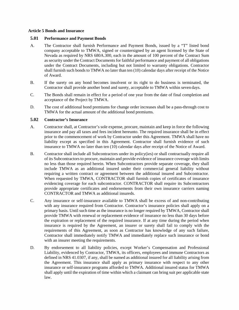
Article 5 Bonds and Insurance
5.01 Performance and Payment Bonds
A. The Contractor shall furnish Performance and Payment Bonds, issued by a “T” listed bond company acceptable to TMWA, signed or countersigned by an agent licensed by the State of Nevada as required by NRS 680A.300, each in the amount of 100 percent of the Contract Sum as security under the Contract Documents for faithful performance and payment of all obligations under the Contract Documents, including but not limited to warranty obligations. Contractor shall furnish such bonds to TMWA no later than ten (10) calendar days after receipt of the Notice of Award.
B. If the surety on any bond becomes insolvent or its right to do business is terminated, the Contractor shall provide another bond and surety, acceptable to TMWA within seven days.
C. The Bonds shall remain in effect for a period of one year from the date of final completion and acceptance of the Project by TMWA.
D. The cost of additional bond premiums for change order increases shall be a pass-through cost to TMWA for the actual amount of the additional bond premiums.
5.02 Contractor’s Insurance A. Contractor shall, at Contractor’s sole expense, procure, maintain and keep in force the following
insurance and pay all taxes and fees incident hereunto. The required insurance shall be in effect prior to the commencement of work by Contractor under this Agreement. TMWA shall have no liability except as specified in this Agreement. Contractor shall furnish evidence of such insurance to TMWA no later than ten (10) calendar days after receipt of the Notice of Award.
B. Contractor shall include all Subcontractors under its policy(ies) or shall contractually require all of its Subcontractors to procure, maintain and provide evidence of insurance coverage with limits no less than those required herein. When Subcontractors provide separate coverage, they shall include TMWA as an additional insured under their commercial general liability without requiring a written contract or agreement between the additional insured and Subcontractor. When requested by TMWA, CONTRACTOR shall furnish copies of certificates of insurance evidencing coverage for each subcontractor. CONTRACTOR shall require its Subcontractors provide appropriate certificates and endorsements from their own insurance carriers naming CONTRACTOR and TMWA as additional insureds.
C. Any insurance or self-insurance available to TMWA shall be excess of and non-contributing with any insurance required from Contractor. Contractor’s insurance policies shall apply on a primary basis. Until such time as the insurance is no longer required by TMWA, Contractor shall provide TMWA with renewal or replacement evidence of insurance no less than 30 days before the expiration or replacement of the required insurance. If at any time during the period when insurance is required by the Agreement, an insurer or surety shall fail to comply with the requirements of this Agreement, as soon as Contractor has knowledge of any such failure, Contractor shall immediately notify TMWA and immediately replace such insurance or bond with an insurer meeting the requirements.
D. By endorsement to all liability policies, except Worker’s Compensation and Professional Liability, evidenced by Contractor, TMWA, its officers, employees and immune Contractors as defined in NRS 41.0307, if any, shall be named as additional insured for all liability arising from the Agreement. This insurance shall apply as primary insurance with respect to any other insurance or self-insurance programs afforded to TMWA. Additional insured status for TMWA shall apply until the expiration of time within which a claimant can bring suit per applicable state law.
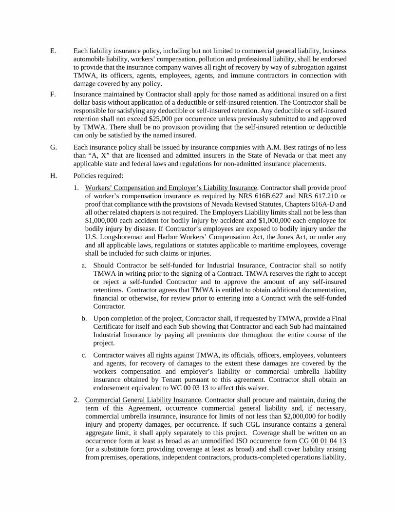
E. Each liability insurance policy, including but not limited to commercial general liability, business automobile liability, workers’ compensation, pollution and professional liability, shall be endorsed to provide that the insurance company waives all right of recovery by way of subrogation against TMWA, its officers, agents, employees, agents, and immune contractors in connection with damage covered by any policy.
F. Insurance maintained by Contractor shall apply for those named as additional insured on a first dollar basis without application of a deductible or self-insured retention. The Contractor shall be responsible for satisfying any deductible or self-insured retention. Any deductible or self-insured retention shall not exceed $25,000 per occurrence unless previously submitted to and approved by TMWA. There shall be no provision providing that the self-insured retention or deductible can only be satisfied by the named insured.
G. Each insurance policy shall be issued by insurance companies with A.M. Best ratings of no less than “A, X” that are licensed and admitted insurers in the State of Nevada or that meet any applicable state and federal laws and regulations for non-admitted insurance placements.
H. Policies required:
1. Workers’ Compensation and Employer’s Liability Insurance. Contractor shall provide proof of worker’s compensation insurance as required by NRS 616B.627 and NRS 617.210 or proof that compliance with the provisions of Nevada Revised Statutes, Chapters 616A-D and all other related chapters is not required. The Employers Liability limits shall not be less than $1,000,000 each accident for bodily injury by accident and $1,000,000 each employee for bodily injury by disease. If Contractor’s employees are exposed to bodily injury under the U.S. Longshoreman and Harbor Workers’ Compensation Act, the Jones Act, or under any and all applicable laws, regulations or statutes applicable to maritime employees, coverage shall be included for such claims or injuries.
a. Should Contractor be self-funded for Industrial Insurance, Contractor shall so notify TMWA in writing prior to the signing of a Contract. TMWA reserves the right to accept or reject a self-funded Contractor and to approve the amount of any self-insured retentions. Contractor agrees that TMWA is entitled to obtain additional documentation, financial or otherwise, for review prior to entering into a Contract with the self-funded Contractor.
b. Upon completion of the project, Contractor shall, if requested by TMWA, provide a Final Certificate for itself and each Sub showing that Contractor and each Sub had maintained Industrial Insurance by paying all premiums due throughout the entire course of the project.
c. Contractor waives all rights against TMWA, its officials, officers, employees, volunteers and agents, for recovery of damages to the extent these damages are covered by the workers compensation and employer’s liability or commercial umbrella liability insurance obtained by Tenant pursuant to this agreement. Contractor shall obtain an endorsement equivalent to WC 00 03 13 to affect this waiver.
2. Commercial General Liability Insurance. Contractor shall procure and maintain, during the term of this Agreement, occurrence commercial general liability and, if necessary, commercial umbrella insurance, insurance for limits of not less than $2,000,000 for bodily injury and property damages, per occurrence. If such CGL insurance contains a general aggregate limit, it shall apply separately to this project. Coverage shall be written on an occurrence form at least as broad as an unmodified ISO occurrence form CG 00 01 04 13 (or a substitute form providing coverage at least as broad) and shall cover liability arising from premises, operations, independent contractors, products-completed operations liability,
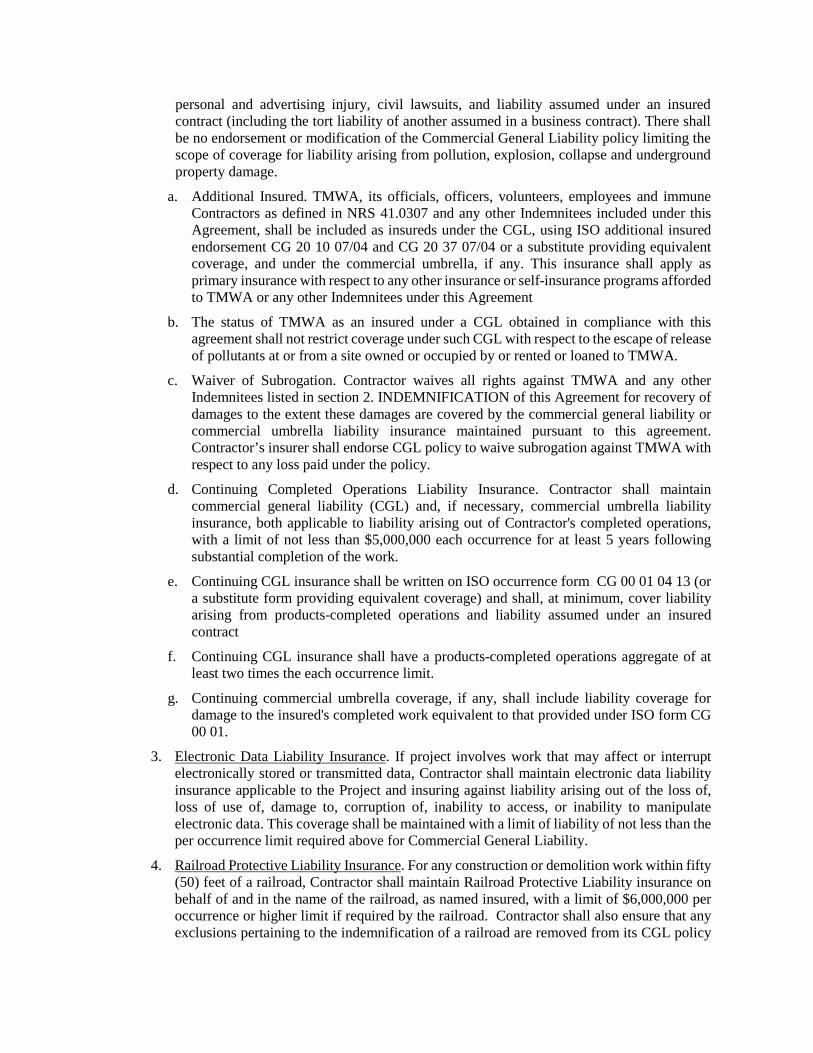
personal and advertising injury, civil lawsuits, and liability assumed under an insured contract (including the tort liability of another assumed in a business contract). There shall be no endorsement or modification of the Commercial General Liability policy limiting the scope of coverage for liability arising from pollution, explosion, collapse and underground property damage.
a. Additional Insured. TMWA, its officials, officers, volunteers, employees and immune Contractors as defined in NRS 41.0307 and any other Indemnitees included under this Agreement, shall be included as insureds under the CGL, using ISO additional insured endorsement CG 20 10 07/04 and CG 20 37 07/04 or a substitute providing equivalent coverage, and under the commercial umbrella, if any. This insurance shall apply as primary insurance with respect to any other insurance or self-insurance programs afforded to TMWA or any other Indemnitees under this Agreement
b. The status of TMWA as an insured under a CGL obtained in compliance with this agreement shall not restrict coverage under such CGL with respect to the escape of release of pollutants at or from a site owned or occupied by or rented or loaned to TMWA.
c. Waiver of Subrogation. Contractor waives all rights against TMWA and any other Indemnitees listed in section 2. INDEMNIFICATION of this Agreement for recovery of damages to the extent these damages are covered by the commercial general liability or commercial umbrella liability insurance maintained pursuant to this agreement. Contractor’s insurer shall endorse CGL policy to waive subrogation against TMWA with respect to any loss paid under the policy.
d. Continuing Completed Operations Liability Insurance. Contractor shall maintain commercial general liability (CGL) and, if necessary, commercial umbrella liability insurance, both applicable to liability arising out of Contractor's completed operations, with a limit of not less than $5,000,000 each occurrence for at least 5 years following substantial completion of the work.
e. Continuing CGL insurance shall be written on ISO occurrence form CG 00 01 04 13 (or a substitute form providing equivalent coverage) and shall, at minimum, cover liability arising from products-completed operations and liability assumed under an insured contract
f. Continuing CGL insurance shall have a products-completed operations aggregate of at least two times the each occurrence limit.
g. Continuing commercial umbrella coverage, if any, shall include liability coverage for damage to the insured's completed work equivalent to that provided under ISO form CG 00 01.
3. Electronic Data Liability Insurance. If project involves work that may affect or interrupt electronically stored or transmitted data, Contractor shall maintain electronic data liability insurance applicable to the Project and insuring against liability arising out of the loss of, loss of use of, damage to, corruption of, inability to access, or inability to manipulate electronic data. This coverage shall be maintained with a limit of liability of not less than the per occurrence limit required above for Commercial General Liability.
4. Railroad Protective Liability Insurance. For any construction or demolition work within fifty (50) feet of a railroad, Contractor shall maintain Railroad Protective Liability insurance on behalf of and in the name of the railroad, as named insured, with a limit of $6,000,000 per occurrence or higher limit if required by the railroad. Contractor shall also ensure that any exclusions pertaining to the indemnification of a railroad are removed from its CGL policy
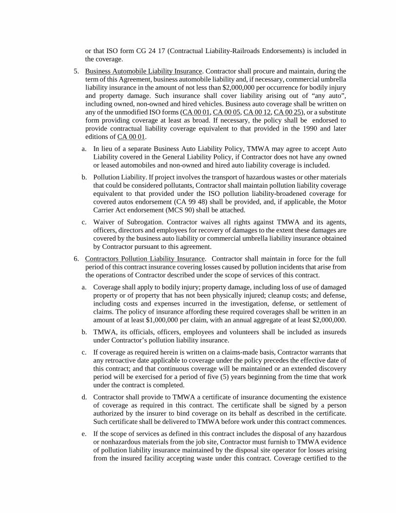
or that ISO form CG 24 17 (Contractual Liability-Railroads Endorsements) is included in the coverage.
5. Business Automobile Liability Insurance. Contractor shall procure and maintain, during the term of this Agreement, business automobile liability and, if necessary, commercial umbrella liability insurance in the amount of not less than $2,000,000 per occurrence for bodily injury and property damage. Such insurance shall cover liability arising out of “any auto”, including owned, non-owned and hired vehicles. Business auto coverage shall be written on any of the unmodified ISO forms (CA 00 01, CA 00 05, CA 00 12, CA 00 25), or a substitute form providing coverage at least as broad. If necessary, the policy shall be endorsed to provide contractual liability coverage equivalent to that provided in the 1990 and later editions of CA 00 01.
a. In lieu of a separate Business Auto Liability Policy, TMWA may agree to accept Auto Liability covered in the General Liability Policy, if Contractor does not have any owned or leased automobiles and non-owned and hired auto liability coverage is included.
b. Pollution Liability. If project involves the transport of hazardous wastes or other materials that could be considered pollutants, Contractor shall maintain pollution liability coverage equivalent to that provided under the ISO pollution liability-broadened coverage for covered autos endorsement (CA 99 48) shall be provided, and, if applicable, the Motor Carrier Act endorsement (MCS 90) shall be attached.
c. Waiver of Subrogation. Contractor waives all rights against TMWA and its agents, officers, directors and employees for recovery of damages to the extent these damages are covered by the business auto liability or commercial umbrella liability insurance obtained by Contractor pursuant to this agreement.
6. Contractors Pollution Liability Insurance. Contractor shall maintain in force for the full period of this contract insurance covering losses caused by pollution incidents that arise from the operations of Contractor described under the scope of services of this contract.
a. Coverage shall apply to bodily injury; property damage, including loss of use of damaged property or of property that has not been physically injured; cleanup costs; and defense, including costs and expenses incurred in the investigation, defense, or settlement of claims. The policy of insurance affording these required coverages shall be written in an amount of at least $1,000,000 per claim, with an annual aggregate of at least $2,000,000.
b. TMWA, its officials, officers, employees and volunteers shall be included as insureds under Contractor’s pollution liability insurance.
c. If coverage as required herein is written on a claims-made basis, Contractor warrants that any retroactive date applicable to coverage under the policy precedes the effective date of this contract; and that continuous coverage will be maintained or an extended discovery period will be exercised for a period of five (5) years beginning from the time that work under the contract is completed.
d. Contractor shall provide to TMWA a certificate of insurance documenting the existence of coverage as required in this contract. The certificate shall be signed by a person authorized by the insurer to bind coverage on its behalf as described in the certificate. Such certificate shall be delivered to TMWA before work under this contract commences.
e. If the scope of services as defined in this contract includes the disposal of any hazardous or nonhazardous materials from the job site, Contractor must furnish to TMWA evidence of pollution liability insurance maintained by the disposal site operator for losses arising from the insured facility accepting waste under this contract. Coverage certified to the
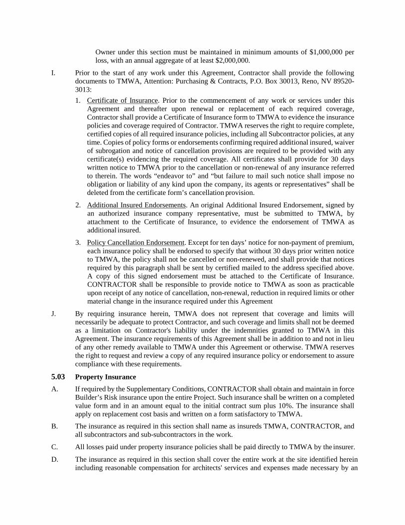
Owner under this section must be maintained in minimum amounts of $1,000,000 per loss, with an annual aggregate of at least $2,000,000.
I. Prior to the start of any work under this Agreement, Contractor shall provide the following documents to TMWA, Attention: Purchasing & Contracts, P.O. Box 30013, Reno, NV 89520-3013: 1. Certificate of Insurance. Prior to the commencement of any work or services under this
Agreement and thereafter upon renewal or replacement of each required coverage, Contractor shall provide a Certificate of Insurance form to TMWA to evidence the insurance policies and coverage required of Contractor. TMWA reserves the right to require complete, certified copies of all required insurance policies, including all Subcontractor policies, at any time. Copies of policy forms or endorsements confirming required additional insured, waiver of subrogation and notice of cancellation provisions are required to be provided with any certificate(s) evidencing the required coverage. All certificates shall provide for 30 days written notice to TMWA prior to the cancellation or non-renewal of any insurance referred to therein. The words “endeavor to” and “but failure to mail such notice shall impose no obligation or liability of any kind upon the company, its agents or representatives” shall be deleted from the certificate form’s cancellation provision.
2. Additional Insured Endorsements. An original Additional Insured Endorsement, signed by an authorized insurance company representative, must be submitted to TMWA, by attachment to the Certificate of Insurance, to evidence the endorsement of TMWA as additional insured.
3. Policy Cancellation Endorsement. Except for ten days’ notice for non-payment of premium, each insurance policy shall be endorsed to specify that without 30 days prior written notice to TMWA, the policy shall not be cancelled or non-renewed, and shall provide that notices required by this paragraph shall be sent by certified mailed to the address specified above. A copy of this signed endorsement must be attached to the Certificate of Insurance. CONTRACTOR shall be responsible to provide notice to TMWA as soon as practicable upon receipt of any notice of cancellation, non-renewal, reduction in required limits or other material change in the insurance required under this Agreement
J. By requiring insurance herein, TMWA does not represent that coverage and limits will necessarily be adequate to protect Contractor, and such coverage and limits shall not be deemed as a limitation on Contractor's liability under the indemnities granted to TMWA in this Agreement. The insurance requirements of this Agreement shall be in addition to and not in lieu of any other remedy available to TMWA under this Agreement or otherwise. TMWA reserves the right to request and review a copy of any required insurance policy or endorsement to assure compliance with these requirements.
5.03 Property Insurance A. If required by the Supplementary Conditions, CONTRACTOR shall obtain and maintain in force
Builder’s Risk insurance upon the entire Project. Such insurance shall be written on a completed value form and in an amount equal to the initial contract sum plus 10%. The insurance shall apply on replacement cost basis and written on a form satisfactory to TMWA.
B. The insurance as required in this section shall name as insureds TMWA, CONTRACTOR, and all subcontractors and sub-subcontractors in the work.
C. All losses paid under property insurance policies shall be paid directly to TMWA by the insurer.
D. The insurance as required in this section shall cover the entire work at the site identified herein including reasonable compensation for architects' services and expenses made necessary by an
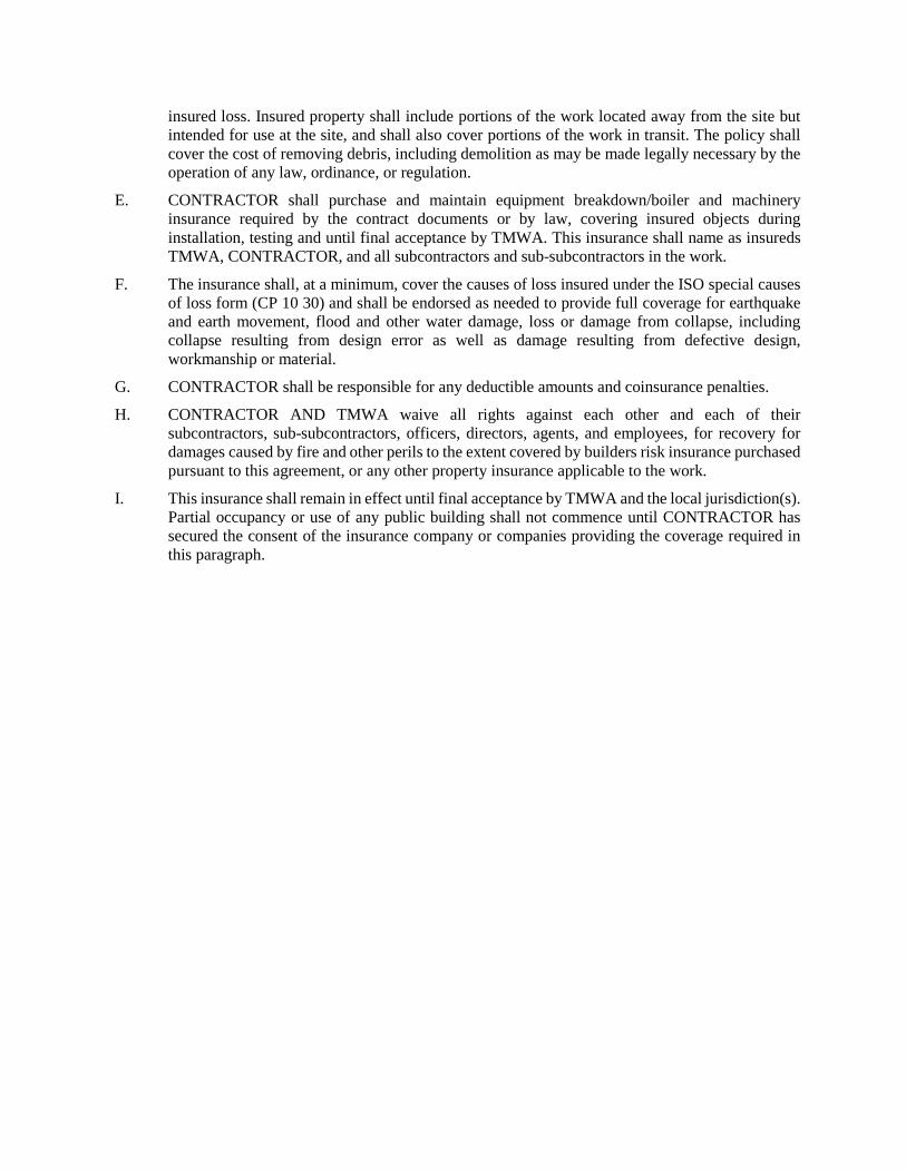
insured loss. Insured property shall include portions of the work located away from the site but intended for use at the site, and shall also cover portions of the work in transit. The policy shall cover the cost of removing debris, including demolition as may be made legally necessary by the operation of any law, ordinance, or regulation.
E. CONTRACTOR shall purchase and maintain equipment breakdown/boiler and machinery insurance required by the contract documents or by law, covering insured objects during installation, testing and until final acceptance by TMWA. This insurance shall name as insureds TMWA, CONTRACTOR, and all subcontractors and sub-subcontractors in the work.
F. The insurance shall, at a minimum, cover the causes of loss insured under the ISO special causes of loss form (CP 10 30) and shall be endorsed as needed to provide full coverage for earthquake and earth movement, flood and other water damage, loss or damage from collapse, including collapse resulting from design error as well as damage resulting from defective design, workmanship or material.
G. CONTRACTOR shall be responsible for any deductible amounts and coinsurance penalties.
H. CONTRACTOR AND TMWA waive all rights against each other and each of their subcontractors, sub-subcontractors, officers, directors, agents, and employees, for recovery for damages caused by fire and other perils to the extent covered by builders risk insurance purchased pursuant to this agreement, or any other property insurance applicable to the work.
I. This insurance shall remain in effect until final acceptance by TMWA and the local jurisdiction(s). Partial occupancy or use of any public building shall not commence until CONTRACTOR has secured the consent of the insurance company or companies providing the coverage required in this paragraph.
Bid Set Supplementary Conditions TMWA June 2018 Mt. Rose Water Treatment Plant 00800 – 1 180101413
SECTION 00800
SUPPLEMENTARY CONDITIONS
SUPPLEMENTARY CONDITIONS GENERAL INFORMATION
I. GENERAL
i. These Supplementary Conditions amend or supplement TMWA’s General Conditions and other provisions of the Contract Documents as indicated below.
ii. All provisions which are not so amended or supplemented remain in full force and effect.
iii. The Project Representative is the sole point of contact for the Contractor on matters relating to the Work. References to “Engineer” or “Architect” in the Specifications shall be understood to mean the Project Representative. The Project Representative for this Project is: Juan C. Esparza, TMWA, P.O. Box 30013 Reno, NV 86520-3013.
ARTICLE 1: DEFINITIONS AND TERMINOLOGY:
Add the following definition:
CCC. “Float” means the amount of time between the project completion deadline and the anticipated project completion date as shown in the progress schedule.
ARTICLE 2: GENERAL AND PRELIMINARY ITEMS:
2.04 ADA REQUIREMENTS:
Add the following to subsection to 2.04:
E. ADA compliance has been design in the Control Room and Bathroom. All other facilities are not required to be ADA compliant.
2.05 NOTICE TO PROCEED: Remove section 2.05 in its entirety and replace with the following:
A. After the Agreement is executed by TMWA, and subject to satisfaction of all conditions necessary thereto, TMWA will issue a Notice to Proceed to Contractor. The date of the NTP begins the Contract Time. Contract Time is defined in the General Conditions.
B. Contractor shall not move onto, store materials, or perform any work at the site prior to the Notice to Proceed.
C. Any mobilization of labor, material or equipment by Contractor prior to TMWA issuing the Notice to Proceed is done at the sole risk and expense of the Contractor, and shall not modify the Contract Time.
D. The allotted Contract Time includes all preliminary Work tasks including permits, surveying, potholing, submittals, etc.
Bid Set Supplementary Conditions TMWA June 2018 Mt. Rose Water Treatment Plant 00800 – 2 180101413
2.06 PRECONSTRUCTION MEETING: Remove section 2.06 in its entirety and change section 2.06 title to PROJECT MEETINGS, and replace with the following:
A. Refer to specification section 01305 – Project Meetings. The following is a list of required or as-needed project meetings as detail in specification section 01305: 1. Preconstruction Meeting
2. Construction Progress Meetings
3. Progress Schedule and Progress Billing
4. Submittal Meetings
5. Quality Assurance Meeting
6. Pre-installation Meetings
7. Post Construction Meetings
8. Change Order Meetings
9. Special Meetings
2.07 SCHEDULES:
Remove subsection 2.07.A.4. and replace with 2.07.A.4. below and add subsections 2.07.A.5 and 2.07.A.6. as detailed below.
4. Refer to specification section 01310 – Construction Schedule, section 01320 – Schedule of Values for additional requirements as to the form and content of the construction schedule, submittal schedule, and schedule of values schedules.
5. Work shall be one hundred percent (100%) complete no later than the date specified in the Agreement. As defined in the Agreement, the Time of Completion is based on a specific number of calendar days after the date of the Notice to Proceed (NTP).
6. Float for any activity, milestone completion date or contract completion date shall be considered a resource available to both the Owner and the Contractor. Neither the Owner nor the Contractor has exclusive ownership of the float. Float shall be a resource to all parties, and shall be consumed by whoever utilizes it first.
2.11 GEOTECHNICAL REPORT
Add the following subsection to section 2.11:
E. In addition to the information above in A-D, Refer to specification section 00320.
ARTICLE 3: CONTRACT DOCUMENTS:
Add the following section 3.01 – Contract Documents and renumber the subsequence sections 3.02 to 3.07:
3.01 CONTRACT DOCUMENTS
A. TMWA will prepare conformed Drawings and Specifications for construction that incorporate all addenda issued during bidding.
B. TMWA will provide up to 10 sets of the conformed documents to the Contractor for use during construction. Additional sets can be obtained at cost. Contractor to coordinate how many full size and half size sets desired within the 10 sets provided.
Bid Set Supplementary Conditions TMWA June 2018 Mt. Rose Water Treatment Plant 00800 – 3 180101413
C. Only conformed documents shall be used for construction. TMWA will not compensate the Contractor for incorrect work done as a result of not using the conformed Drawings and Specifications.
3.02 EXAMINATION OF CONTRACT DOCUMENTS: Change section 3.01 examination of contract documents to 3.02. All other content to remain as detail in General Conditions.
3.03 INTENT AND CORRELATION: Change section to 3.02 intent and correlation to 3.03. All other content to remain as detail in General Conditions
3.04 STANDARDS: Change section 3.03 Standards to 3.04. All other content to remain as detail in General Conditions.
3.05 WORK CHANGE DIRECTIVE: Change section 3.04 Work Change Directive to 3.05. All other content to remain as detail in General Conditions.
3.06 CHANGES TO THE CONTRACT: Change section 3.05 Changes to the Contract to 3.06. Replace subsection to 3.06.G with the following:
G. The labor and equipment rates described in Article 7.04 “Extra Work – Payment for Time and Material Work” of the General Conditions shall be used as the basis for pricing lump sum Change Orders and for unit price adjustments. The labor and equipment rates apply to both additive and deductive change orders and unit price adjustments.
Add the following to subsection 3.06.H H. Specification section 01350 – Contract Modification Procedures shall be supplemental to this
section.
3.07 OWNERSHIP AND RETURN OF CONTRACT DOCUMENTS Change section 3.06 Ownership and return of Contract Documents to 3.07. Add the following sentence to the end of subsection to 3.07.B.:
B. All copies shall be returned to the Project Representative before payment will be made for demobilization and before a Notice of Completion will be filed.
ARTICLE 4: PHYSICAL CONDITIONS, LANDS, REFERENCE POINTS:
4.06 ROCK EXCAVATION:
Replace subsection 4.06.C with the following:
C. Blasting is not permitted.
ARTICLE 5: BONDS AND INSURANCE:
5.02 CONTRACTOR’S INSURANCE:
General Liability Insurance limits shall be $10,000,000. Replace the first and second sentences of subsection 5.02.H.2 with the following:
2. Commercial General Liability Insurance. Contractor shall procure and maintain, during the term of this Agreement, occurrence commercial general liability and, if necessary,
Bid Set Supplementary Conditions TMWA June 2018 Mt. Rose Water Treatment Plant 00800 – 4 180101413
commercial umbrella insurance, insurance for limits of not less than $10,000,000 for bodily injury and property damages, per occurrence.
5.03 PROPERTY INSURANCE:
Property Insurance is required for this project. Replace Subsection 5.03.A with the following:
A. CONTRACTOR shall obtain and maintain in force Builder’s Risk insurance upon the entire Project. Such insurance shall be written on a completed value form and in an amount equal to the initial contract sum plus 10%. The insurance shall apply on replacement cost basis and written on a form satisfactory to TMWA.
ARTICLE 6: CONTRACTOR’S RESPONSIBILITIES
6.05 MATERIALS:
Add the following sentence to subsection 6.05.B.
B. Reference specification section 01640 – Product Handling for additional equipment storing and protection requirements.
6.06 PERMITS:
Replace subsection 6.6.A.2 with the following:
2. Contractor shall provide a stockpiling permit if required by Washoe County.
Add the following sentence to subsections to 6.06.A.3
3. The estimated area of land that will be disturbed by the Project is greater than one acre. The Contractor, as operator of the site, shall prepare a Stormwater Pollution Prevention Plan (SWPPP), submit a Notice of Intent (NOI) to NDEP, and pay the required fee.
Add the following subsection to 6.06.B: 7. US ARMY CORPS OF ENGINEERS 404 PERMIT: TMWA has obtained a US Army Corps
of Engineers 404 Permit for construction in Whites Creek. Contractor shall comply with all construction activity related requirements and conditions contained within the Permit. A copy of the Permit is provided in the Appendix.
8. NDEP TEMPORARY WORKING IN WATERWAYS PERMIT: TMWA has obtained a NDEP Temporary Working in Waterways Permit for construction activities in Whites Creek. Contractor shall comply with all requirements and conditions contained within the Permit. A copy of the Permit is provided in the Appendix.
9. WASHOE COUNTY AIR QUALITY MANAGEMENT DIVISION PERMIT: Contractor shall submit engine emissions data and required fees and obtain a “Permit to Construct” from WCAQMD in the Owner’s name prior to delivery of engine-generator set to job-site.
6.07 SUBMITTALS FOR ITEMS THAT WILL BE INCORPORATED INTO THE WORK OR REQUESTS FOR INFORMATION
Replace section 6.07.E.4 with the following: 4. Submittals will be marked in one of seven ways.
i. Approved as Submitted.
Bid Set Supplementary Conditions TMWA June 2018 Mt. Rose Water Treatment Plant 00800 – 5 180101413
ii. Approved as Noted.
iii. Disapproved Make Corrections – Resubmittal Required.
iv. Disapproved as Noted Develop Replacement – Resubmittal Required.
v. Incomplete. Complete and Resubmit – Resubmittal Required.
vi. Incomplete. Submit Missing Portions – Resubmittal Required.
vii. For Record Only – Not Reviewed
6.13 PROTECTION OF EXISTING VEGETATION AND IMPROVEMENTS
Add the following sentences to subsection 6.13.B.: B. An onsite meeting with TMWA and the Engineer shall take place before cutting any trees in
Whites Creek. During that meeting TMWA and the Engineer will identify trees that will be protected in place during construction.
6.14 CONSTRUCTION SITE STORMWATER CONTROL
Add the following to subsection 6.14.B.: 3. The Contractor shall provide a Stormwater Pollution Prevention Plan (SWPPP) for this
project in accordance with the details in the General Conditions.
6.17 RECORD DRAWINGS
Add the following to section 6.17: D. The Contractor shall submit with their monthly pay application a signed document from the
TMWA project representative that record drawings located on Procore are up to date. No payment will be made until this document is provided.
6.18 WARRANTY
Add the following to section 6.18 G. All manufacturer equipment warranties, unless specifically agree to by TMWA, shall start
from date of “beneficial use” as agreed in writing by the TMWA representative and shall not start from date of delivery.
H. The Contractor shall keep record or all equipment warranties in a table with at a minimum the following headings: Equipment, Manufacturer Name, Manufacturer Information, Warranty Start Date, Warranty End Date, and Specific Notes of Warranty Limitations. The final Warranty table shall be submitted to TMWA at the end of the project.
ARTICLE 7: PAYMENT AND RETENTION:
7.02 PROGRESS PAYMENTS
Add the following items to section 7.02: F. Before a progress payment will be accepted the Contractor shall submit a document signed
from the TMWA’s project representative that the Record Drawings located on Procore are up to date.
G. Contractor’s pay application cover sheet shall be completed on the EJCDC C620 document. TMWA will provide this document in Excel format for the Contractor’s use.
7.03 EXTRA WORK – REQUEST FOR APPROVAL
Add the following to section 7.03:
Bid Set Supplementary Conditions TMWA June 2018 Mt. Rose Water Treatment Plant 00800 – 6 180101413
E. Lump sum extra work proposals at a minimum shall follow the requirements detailed in specification section 01350.
7.06 RETENTION AND FINAL PAYMENT
Add the following to section 7.06: E. Project closeout starts when the Contractor submits a letter to the Project Representative stating
that the Project is complete and requesting release of retention.
F. The project closeout process is part of the Work and must be completed within the specified Contract Time.
G. Procedure: Reference Specification Section 01700 for project closeout requirements.
H. If the Project is complete, the Project Representative will submit the required documentation to TMWA’s Contracts Administrator and request that the Notice of Completion be issued. The one year warranty required by Article 6.18 “Warranty” of the General Conditions shall start on the date of the Project Representative’s determination that the project is complete.
I. If the Project is not complete, the Project Representative will notify the Contractor in writing of items that need to be completed or submitted before the Project will be considered complete.
ARTICLE 8: TIME EXTENSIONS AND DELAYS:
8.01 TIME EXTENSIONS
Add the following to section 8.01: C. Time Extensions shall be requested with each Potential Change Order and shall provide
explanation of how the extra work affects the critical path of the work. Contractor shall be responsible for updating their project schedule to show how the extra work warrants a Time Extension.
ARTICLE 9: SUSPENSION AND TERMINATION OF WORK: No Changes to this Article.
ARTICLE 10: OTHER PROVISIONS:
10.02 INSPECTION AND TESTING BY TMWA
Add the following to section 10.02: F. For additional Testing information please reference Specification Sections 01010 3.7.
ARTICLE 11: MISCELLANEOUS LEGAL PROVISIONS: No Changes to this Article.
END OF SUPPLEMENTARY CONDITIONS
Bid Set Electric Motors TMWA June 2018 Mt. Rose Water Treatment Plant 16460-1 180101413
SECTION 16460
ELECTRIC MOTORS
PART 1 GENERAL
1.1 THE SUMMARY
A. General: The CONTRACTOR shall provide electric motors, accessories, and appurtenances complete and operable, in conformance to the Contract Documents.
B. The provisions of this Section apply to low voltage 3 phase, AC squirrel cage induction motors throughout the Contract Documents, except as indicated otherwise.
C. The CONTRACTOR shall assign to the equipment supplier the responsibility to select suitable electric motors for the equipment. The choice of motor manufacturer shall be subject to review by the ENGINEER. Such review will consider future availability of replacement parts and compatibility with driven equipment
1.2 CONTRACTOR SUBMITTALS
A. Furnish submittals in accordance with Section 01300 - Contractor Submittals and 16050 – Electrical Work, General.
B. Complete motor data shall be submitted with the driven machinery Shop Drawings. Motor data shall include:
1. Machine name and specification number of driven machine
2. Motor manufacturer
3. Motor type or model and dimension drawing. Include motor weight.
4. Nominal horsepower
5. NEMA design
6. Enclosure
7. Frame size
8. Winding insulation class and temperature rise class
9. Voltage, phase, and frequency ratings
10. Service factor
11. Full load current at rated horsepower for application voltage
12. Full load speed
13. Guaranteed minimum full load efficiency. Also nominal efficiencies at 1/2 and 3/4 load.
14. Type of thermal protection or overtemperature protection, where included
15. Wiring diagram for devices such as motor leak detection, temperature, or zero speed switches, as applicable
Bid Set Electric Motors TMWA June 2018 Mt. Rose Water Treatment Plant 16460-2 180101413
16. Bearing data. Include recommendation for lubricants of relubricatable type bearings.
17. If utilized with a variable frequency controller, verify motor is inverter duty type. Include minimum speed at which motor may be operated for the driven machinery. Provide shaft grounding details and information. Provide insulated bearing details and information.
18. Power factor at 1/2, 3/4 and full load.
19. Recommended size for power factor correction capacitors to improve power factor to 0.95 percent lagging when operated at full load.
C. If water cooling is required for motor thrust bearings, the Shop Drawing submittals shall indicate this requirement.
PART 2 PRODUCTS
2.1 GENERAL REQUIREMENTS
A. Electric motors driving identical machines shall be identical.
B. Maximum motor loading shall be equal to nameplate horsepower rating or less, exclusive of service factor and be verifiable from the submittal data of the driven machinery.
C. Motor Capacity
1. The CONTRACTOR supplying the driven machinery shall size motors for the larger of the following criteria:
a. Size motors to continuously carry the maximum load that develops across the full range of driven equipment operation.
b. Size motors for minimum size indicated
2. In every case, motor size shall be derated from nameplate values as follows:
a. Ambient Temperature
1) For ambient temperatures up to but not exceeding 40 degrees C, no derating is required.
2) For ambient temperatures exceeding 40 degrees but less than 50 degrees C, derate nameplate HP ratings to 85 percent.
b. Site Altitude: Derate motor for operation at 6,000 ft.
3. Increased circuit breaker, magnetic starter, and conductor and conduit capacities required for motors larger than the indicated sizes shall be provided as part of the WORK.
D. Exempt Motors: Motors for valve operators, submersible pumps, or motors which are an integral part of standard manufactured equipment, i.e., non-NEMA mounting, common shaft with driven element, or part of domestic or commercial use apparatus may be excepted from these requirements to the extent that such variation reflects a necessary condition of motor service or a requirement of the driven equipment.
2.2 DESIGN REQUIREMENTS
A. General: Electric motors shall comply with NEMA MG-1 - Motor and Generator. Motors used with adjustable frequency drives shall comply with NEMA MG-1, Part 31, and shall be clearly identified as “Inverter Duty.”
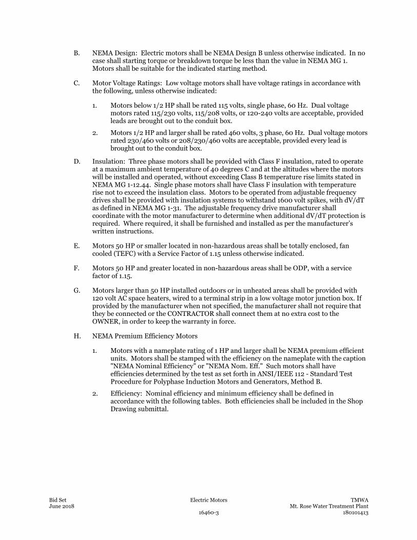
Bid Set Electric Motors TMWA June 2018 Mt. Rose Water Treatment Plant 16460-3 180101413
B. NEMA Design: Electric motors shall be NEMA Design B unless otherwise indicated. In no case shall starting torque or breakdown torque be less than the value in NEMA MG 1. Motors shall be suitable for the indicated starting method.
C. Motor Voltage Ratings: Low voltage motors shall have voltage ratings in accordance with the following, unless otherwise indicated:
1. Motors below 1/2 HP shall be rated 115 volts, single phase, 60 Hz. Dual voltage motors rated 115/230 volts, 115/208 volts, or 120-240 volts are acceptable, provided leads are brought out to the conduit box.
2. Motors 1/2 HP and larger shall be rated 460 volts, 3 phase, 60 Hz. Dual voltage motors rated 230/460 volts or 208/230/460 volts are acceptable, provided every lead is brought out to the conduit box.
D. Insulation: Three phase motors shall be provided with Class F insulation, rated to operate at a maximum ambient temperature of 40 degrees C and at the altitudes where the motors will be installed and operated, without exceeding Class B temperature rise limits stated in NEMA MG 1-12.44. Single phase motors shall have Class F insulation with temperature rise not to exceed the insulation class. Motors to be operated from adjustable frequency drives shall be provided with insulation systems to withstand 1600 volt spikes, with dV/dT as defined in NEMA MG 1-31. The adjustable frequency drive manufacturer shall coordinate with the motor manufacturer to determine when additional dV/dT protection is required. Where required, it shall be furnished and installed as per the manufacturer’s written instructions.
E. Motors 50 HP or smaller located in non-hazardous areas shall be totally enclosed, fan cooled (TEFC) with a Service Factor of 1.15 unless otherwise indicated.
F. Motors 50 HP and greater located in non-hazardous areas shall be ODP, with a service factor of 1.15.
G. Motors larger than 50 HP installed outdoors or in unheated areas shall be provided with 120 volt AC space heaters, wired to a terminal strip in a low voltage motor junction box. If provided by the manufacturer when not specified, the manufacturer shall not require that they be connected or the CONTRACTOR shall connect them at no extra cost to the OWNER, in order to keep the warranty in force.
H. NEMA Premium Efficiency Motors
1. Motors with a nameplate rating of 1 HP and larger shall be NEMA premium efficient units. Motors shall be stamped with the efficiency on the nameplate with the caption "NEMA Nominal Efficiency" or "NEMA Nom. Eff." Such motors shall have efficiencies determined by the test as set forth in ANSI/IEEE 112 - Standard Test Procedure for Polyphase Induction Motors and Generators, Method B.
2. Efficiency: Nominal efficiency and minimum efficiency shall be defined in accordance with the following tables. Both efficiencies shall be included in the Shop Drawing submittal.
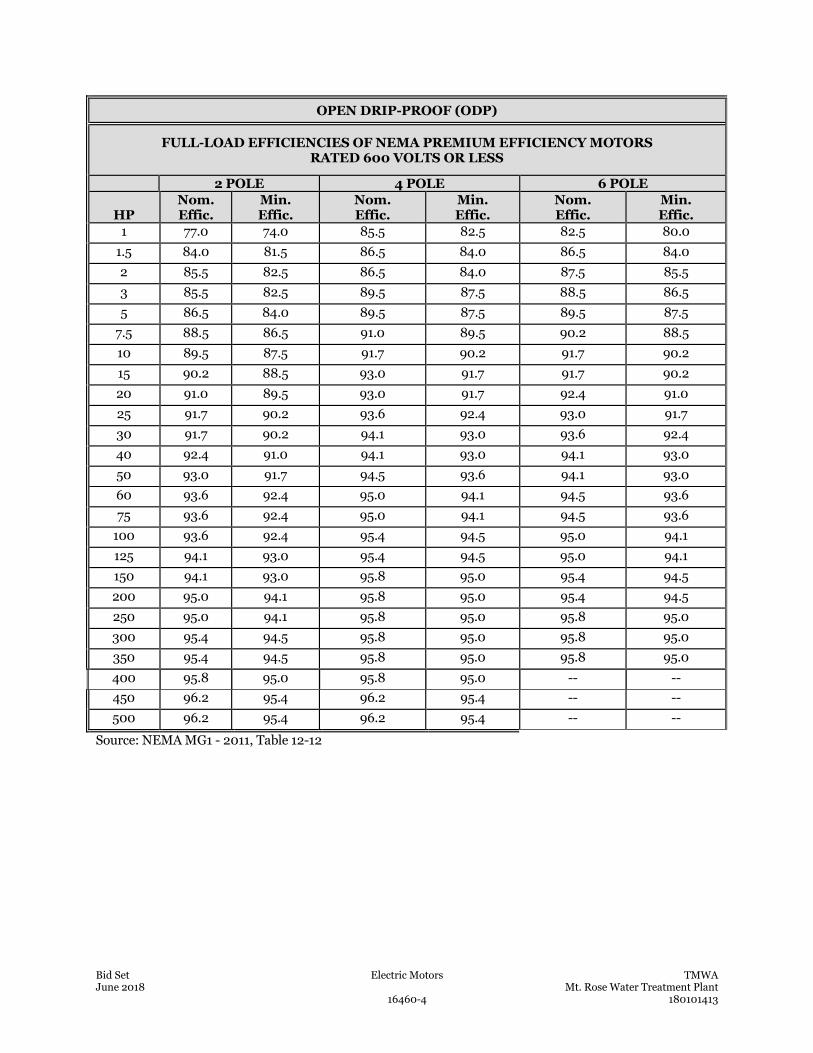
Bid Set Electric Motors TMWA June 2018 Mt. Rose Water Treatment Plant 16460-4 180101413
OPEN DRIP-PROOF (ODP)
FULL-LOAD EFFICIENCIES OF NEMA PREMIUM EFFICIENCY MOTORS RATED 600 VOLTS OR LESS
2 POLE 4 POLE 6 POLE
HP Nom. Effic.
Min. Effic.
Nom. Effic.
Min. Effic.
Nom. Effic.
Min. Effic.
1 77.0 74.0 85.5 82.5 82.5 80.0 1.5 84.0 81.5 86.5 84.0 86.5 84.0 2 85.5 82.5 86.5 84.0 87.5 85.5 3 85.5 82.5 89.5 87.5 88.5 86.5 5 86.5 84.0 89.5 87.5 89.5 87.5
7.5 88.5 86.5 91.0 89.5 90.2 88.5 10 89.5 87.5 91.7 90.2 91.7 90.2 15 90.2 88.5 93.0 91.7 91.7 90.2 20 91.0 89.5 93.0 91.7 92.4 91.0 25 91.7 90.2 93.6 92.4 93.0 91.7 30 91.7 90.2 94.1 93.0 93.6 92.4 40 92.4 91.0 94.1 93.0 94.1 93.0 50 93.0 91.7 94.5 93.6 94.1 93.0 60 93.6 92.4 95.0 94.1 94.5 93.6 75 93.6 92.4 95.0 94.1 94.5 93.6
100 93.6 92.4 95.4 94.5 95.0 94.1 125 94.1 93.0 95.4 94.5 95.0 94.1 150 94.1 93.0 95.8 95.0 95.4 94.5 200 95.0 94.1 95.8 95.0 95.4 94.5 250 95.0 94.1 95.8 95.0 95.8 95.0 300 95.4 94.5 95.8 95.0 95.8 95.0 350 95.4 94.5 95.8 95.0 95.8 95.0 400 95.8 95.0 95.8 95.0 -- -- 450 96.2 95.4 96.2 95.4 -- -- 500 96.2 95.4 96.2 95.4 -- --
Source: NEMA MG1 - 2011, Table 12-12
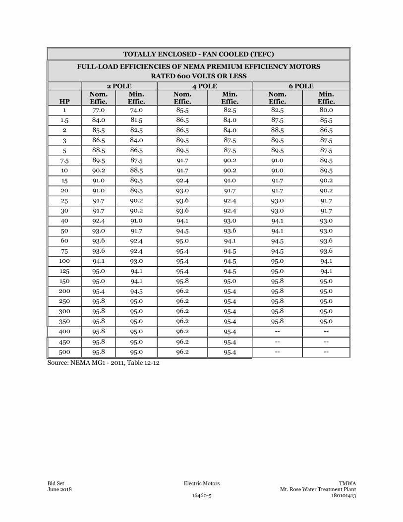
Bid Set Electric Motors TMWA June 2018 Mt. Rose Water Treatment Plant 16460-5 180101413
TOTALLY ENCLOSED - FAN COOLED (TEFC)
FULL-LOAD EFFICIENCIES OF NEMA PREMIUM EFFICIENCY MOTORS RATED 600 VOLTS OR LESS
2 POLE 4 POLE 6 POLE
HP Nom. Effic.
Min. Effic.
Nom. Effic.
Min. Effic.
Nom. Effic.
Min. Effic.
1 77.0 74.0 85.5 82.5 82.5 80.0 1.5 84.0 81.5 86.5 84.0 87.5 85.5 2 85.5 82.5 86.5 84.0 88.5 86.5 3 86.5 84.0 89.5 87.5 89.5 87.5 5 88.5 86.5 89.5 87.5 89.5 87.5
7.5 89.5 87.5 91.7 90.2 91.0 89.5 10 90.2 88.5 91.7 90.2 91.0 89.5 15 91.0 89.5 92.4 91.0 91.7 90.2 20 91.0 89.5 93.0 91.7 91.7 90.2 25 91.7 90.2 93.6 92.4 93.0 91.7 30 91.7 90.2 93.6 92.4 93.0 91.7 40 92.4 91.0 94.1 93.0 94.1 93.0 50 93.0 91.7 94.5 93.6 94.1 93.0 60 93.6 92.4 95.0 94.1 94.5 93.6 75 93.6 92.4 95.4 94.5 94.5 93.6
100 94.1 93.0 95.4 94.5 95.0 94.1 125 95.0 94.1 95.4 94.5 95.0 94.1 150 95.0 94.1 95.8 95.0 95.8 95.0 200 95.4 94.5 96.2 95.4 95.8 95.0 250 95.8 95.0 96.2 95.4 95.8 95.0 300 95.8 95.0 96.2 95.4 95.8 95.0 350 95.8 95.0 96.2 95.4 95.8 95.0 400 95.8 95.0 96.2 95.4 -- --
450 95.8 95.0 96.2 95.4 -- -- 500 95.8 95.0 96.2 95.4 -- --
Source: NEMA MG1 - 2011, Table 12-12
Bid Set Electric Motors TMWA June 2018 Mt. Rose Water Treatment Plant 16460-6 180101413
I. Two speed motors shall be of the 2 winding type.
2.3 ACCESSORY REQUIREMENTS
A. General: Horizontal motors 3 HP and larger and every vertical motor shall have split-type cast metal conduit boxes. Motors shall be provided with oversized conduit boxes. Where conduit sizes indicated do not match the motor terminal box, the CONTRACTOR shall provide means to accommodate the motor requirements. Motor boxes other than open drip-proof shall be gasketed.
B. Lifting Devices: Motors weighing 265 lb (120 Kg) or more shall have suitable lifting eyes for installation and removal.
C. Special Requirements: The CONTRACTOR shall refer to individual equipment specifications for special requirements such as motor winding thermal protection or multi-speed windings.
D. Grounding Lugs: Provide motor grounding lug suitable to terminate ground wire, sized as indicated.
E. Nameplate: Motors shall be fitted with permanent stainless steel nameplates indelibly stamped or engraved with NEMA Standard motor data, in conformance with NEMA MG-1-10.40. Inverter duty motors shall be clearly identified as such.
F. Where motors are indicated by elementary schematics or specifications to have zero speed switches, the switches shall be factory mounted integral to the motors. Switches shall close the contacts when the motor is at zero speed.
G. Inverter duty motors shall be provided with shaft grounding rings. Rings shall be factory installed, and shall be manufactured by Aegis, or equal. The motor warranty shall include coverage against VFD-induced bearing damage or failure.
2.4 MOTOR THERMAL PROTECTION
A. Single Phase Motors: Single phase 120, 208, or 230 volt motors shall have integral thermal overload protection or shall be inherently current limited.
B. Thermostats: Where indicated or specified, winding thermostats shall be resistance temperature detector (RTD) type. Thermostats shall be provided with one normally closed contact. The thermostat switch point shall be precalibrated by the manufacturer. All inverter duty motors shall be provided with winding thermostats.
C. RTD: Provide Pyromation R1T185L483-002-00-8HN31-T440-385U-S(0-150)C, no equal.
2.5 MOTOR BEARINGS
A. General: Bearings shall conform to Section 11000 - Equipment General Provisions, except as indicated herein.
B. Motors greater than 2 HP shall have bearings designed for 17,500 hours (belted) or 100,000 hours (coupled) L-10 life.
C. Fractional Horsepower: Motors with fractional horsepower through 2 HP shall be provided with lubricated-for-life ball bearings.
Bid Set Electric Motors TMWA June 2018 Mt. Rose Water Treatment Plant 16460-7 180101413
D. Horizontal Motors Over 2 HP: Motors larger than 2 HP shall be provided with relubricatable ball bearings. Lubrication shall be per manufacturer's recommendation for smooth operation and long life of the bearings.
E. Vertical Motors Over 2 HP: Vertical motors larger than 2 HP shall be provided with relubricatable ball, spherical, roller, or plate type thrust bearings. Lubrication shall be per manufacturer's recommendation for smooth operation and long life of the bearings.
F. Water Cooled Motors: If water cooling is required for the thrust bearings, cooling water lines shall be provided complete with shut-off valve, strainer, solenoid valve, flow indicator, thermometer, throttling valve, and, (where subject to freezing), insulation with heat tracing.
G. Inverter Duty Motors: Provide an insulated bearing to prevent circulating bearing currents.
2.6 MANUFACTURERS, OR EQUAL
A. Baldor
B. U.S. Motors/Nidec
C. WEG
PART 3 EXECUTION
3.1 INSTALLATION
A. Motor installation shall be performed in accordance with the motor manufacturer's written recommendations and the written requirements of the manufacturer of the driven equipment. Shaft grounding devices shall be connected to the grounding system in accordance with the manufacturer’s recommendations.
B. Related electrical WORK involving connections, controls, switches, and disconnects shall be performed in accordance with the applicable sections of Division 26.
3.2 FACTORY TESTING
A. Motors rated 100 HP and larger shall be factory tested in conformance with IEEE 112, IEEE 43 - Recommended Practice for Testing Resistance of Rotating Machinery, and NEMA MG-2. Except where specific testing or witnessed shop tests are required by the specifications for driven equipment, factory test reports may be copies of routine test reports of electrically duplicate motors. Test report shall indicate test procedure and instrumentation used to measure and record data. Test report shall be certified by the motor manufacturer's test personnel and be submitted to the ENGINEER.
3.3 FIELD TESTING
A. The CONTRACTOR shall perform the following field tests (see also Section 16950 – Electrical Testing):
1. Inspect each motor installation for any deviation from rated voltage, phase, frequency, and improper installation.
2. Visually check for proper phase and ground connections. Verify that multi-voltage motors are connected for proper voltage. Verify shaft grounding devices are properly grounded.
Bid Set Electric Motors TMWA June 2018 Mt. Rose Water Treatment Plant 16460-8 180101413
3. Check winding and bearing temperature detectors and space heaters for functional operation.
4. Test for proper rotation prior to connection to the driven equipment.
5. Visually check that motor overload heaters are properly sized and that MCP breaker settings are correct for the motor installed.
6. Test insulation (megger test) of new and re-used motors in accordance with NEMA MG-1. Test voltage shall be 1000 VAC plus twice the rated voltage of the motor.
END OF SECTION
Bid Set Low-Voltage Motor Control Centers TMWA June 2018 Mt. Rose Water Treatment Plant 16480-1 180101413
SECTION 16480
LOW-VOLTAGE MOTOR CONTROL CENTERS
PART 1 GENERAL
1.1 THE SUMMARY
A. The CONTRACTOR shall provide motor control centers (MCCs), complete and operable, in accordance with the Contract Documents.
B. The requirements of Section 16050 – Electrical Work, General, apply to the WORK of this Section.
C. In the event that provided motors are of greater horsepower than the indicated motors, revise the raceways, conductors, starters, overload elements, and branch circuit protectors as necessary in order to control and protect the increased motor horsepower in accordance with Section 16460 – Electric Motors.
D. Single Manufacturer
1. The MCCs shall be the end product of one manufacturer in order to standardize appearance, operation, maintenance, spare parts, and manufacturer's services.
2. This requirement, however, does not relieve the CONTRACTOR of overall responsibility for the WORK.
E. Coordination
1. The equipment provided under this Section shall operate the electric motor driver with the driven equipment as indicated under other equipment Sections.
2. The MCC manufacturer shall be provided with the following information, at a minimum:
a. Section 11000 – Equipment General Provisions
b. Relevant Division 11 and Division 15 Sections for each piece of equipment driven by the MCC
c. Section 16050 – Electrical Work, General
d. Section 16460 – Electric Motors
e. Section 16485 – Local Control Stations And Miscellaneous Electrical Devices
f. Section 16950 – Electrical Tests
g. The Electrical Contract Drawings
1.2 CONTRACTOR SUBMITTALS
A. Furnish submittals in accordance with Section 01300 – Submittals and Section 16050 – Electrical Work, General.
B. Furnish the following equipment information in the Shop Drawings:
Bid Set Low-Voltage Motor Control Centers TMWA June 2018 Mt. Rose Water Treatment Plant 16480-2 180101413
1. NEMA rating and color of enclosure
2. horizontal and vertical bus ampacities, voltage rating, interrupting capacity, and materials of construction
3. ground bus size and material of construction
4. conduit entrance provisions
5. main incoming line entry provision (top or bottom)
6. control unit nameplate schedule
7. circuit breaker types, frames, and settings
8. starter NEMA sizes, auxiliary contact provisions, and coil voltage
9. relays, timers, pilot devices, control transformer VA and fuse sizes
10. MCC Ladder Diagrams
a. Furnish custom elementary schematic ladder diagrams for each compartment.
b. The ladder diagrams shall include remote devices.
c. Submittals not meeting these requirements will not be reviewed further and will be returned to the CONTRACTOR.
11. short circuit rating of the complete assembly
12. replacement parts lists and operation and maintenance procedures
13. seismic design certification of the anchoring system in accordance with Section 16050 – Electrical Work, General
14. time-current curves for protective devices
15. RVSS and VFD Equipment Information
a. name of starter and drive manufacturer
b. type and complete model number
c. assembly drawing and nomenclature, including enclosure dimensions, mounting and anchoring details, and internal layout
d. detailed schematics, including external wiring connections
e. maximum heat dissipation capacity in kW
f. altitude de-rating information
16. factory test data certifying compliance with requirements of similar equipment from the same manufacturer
C. Furnish an Owner's Manual, including:
1. manufacturer's two-year warranty
2. field test report
D. Furnish the Manufacturer's Service Representative's resume, including the following documentation:
1. copy of the proposed representative's Factory Training Certificate
2. number of years experience servicing the manufacturer’s MCCs and VFDs
Bid Set Low-Voltage Motor Control Centers TMWA June 2018 Mt. Rose Water Treatment Plant 16480-3 180101413
3. a statement that the individual is authorized to inspect, test and perform field service and repairs
E. Spare Parts List
1. Furnish spare parts information for parts required by this Section as well any other spare parts recommended by the MCC manufacturer.
F. Startup and Testing Report
1. Within 15 days after completion of startup and testing, the CONTRACTOR shall submit a report for the MCC.
2. The report shall contain the following documentation:
a. the device name, serial number, rating, and complete model number of each MCC
b. a complete listing of all tests performed and the results of each test
c. a complete listing of all circuit breaker and overload settings, fuse ratings, settings, setpoints and configuration information for VFDs and equipment or devices with adjustable settings
d. documentation for training that was provided to the OWNER’s personnel, including topics covered, instructor's name and contact information, and a list of attendees
PART 2 PRODUCTS
2.1 GENERAL
A. The manufacturer of the low-voltage motor control center shall also manufacture at least the following:
1. molded case circuit breakers, up to and including 225 ampere frame size
2. disconnect switches
3. magnetic motor starters
4. control and timing relays rated at 600 volts AC
5. pushbuttons, lights and selector switches, including remote mounted control stations
6. meters, including ammeter, voltmeter, and solid-state metering devices
B. Single Manufacturer
1. Devices of the same type shall be products of the same manufacturer.
2. This requirement applies to control devices, custom-fabricated equipment, and insofar as practical to equipment manufactured on a production basis.
C. Lighting transformers and panelboards shall be in accordance with the requirements of Section 16470 – Panelboards and General Purpose Dry-Type Transformers.
D. Motor control centers shall conform to the standards for NEMA Class IIS, Type B diagrams and wiring.
Bid Set Low-Voltage Motor Control Centers TMWA June 2018 Mt. Rose Water Treatment Plant 16480-4 180101413
2.2 DESIGN, CONSTRUCTION, AND MATERIAL REQUIREMENTS
A. The motor control centers shall be 600-volt class and suitable for operation on a 3-phase, 60-Hz system.
B. The system operating voltage and number of wires shall be as indicated.
C. Power
1. Power distribution from the MCC shall be 480-volt, 3-phase, 3- wire.
2. The MCC shall include provision for termination of an incoming neutral conductor in conformance to NEC requirements for service entrance.
D. Enclosure
1. The enclosure shall be as noted on contract drawings.
2. The variable frequency drive (VFD) and solid-state soft starter (RVSS) compartments may be of NEMA Type 1, gasketed, provided that ventilation inlet openings are covered by externally replaceable dust filters.
3. Compartment doors shall be interlocked with compartment circuit breakers, fitted with a maintenance override.
4. Latches for panelboard compartments shall have butterfly heads or another hand operable method that does not require tools to operate.
E. Size and Arrangement
1. Motor control centers shall be configured as mechanical groupings of control center units, assembled into a lineup of control center sections.
2. Each control section shall be nominally 90 inches tall by a minimum of 20 inches deep.
3. MCCs shall be designed to not exceed the indicated spatial requirements, including spaces, spares, and future compartments.
4. MCCs shall be subject to rejection if they exceed the indicated lengths, where allotted space is critical.
5. Equipment within the MCC may be rearranged at the discretion of the manufacturer, providing that the MCC includes the spares, space, and future provisions as indicated, and that panelboards are either at the top of their sections or the bottoms are at least 36 inches above the housekeeping pad.
6. Switches and circuit breakers used as switches shall be located such that the center of the grip of the operating handle of the switch or circuit breaker, when in its highest position, will not be more than 6 feet, 7 inches above the floor, including the height of the concrete pad.
F. Components
1. Busses
a. Provide a continuous copper ground bus, full width of the motor control center line-up.
b. Horizontal Busses
1) The main horizontal bus shall be of tin-plated copper, and located within an isolated compartment.
Bid Set Low-Voltage Motor Control Centers TMWA June 2018 Mt. Rose Water Treatment Plant 16480-5 180101413
2) The bus shall be rated for 600 amperes minimum, but in no case less than the main lug or main breaker frame size.
c. Vertical Busses
1) The vertical bus in each section shall consist of a single tin-plated copper conductor per phase, with a current capacity of not less than 300 amps.
2) The vertical bus shall be completely isolated and insulated, and shall extend the full height of the section wherever possible.
d. Power buses shall be braced to withstand 65,000 amperes, minimum.
2. Wireways
a. Provide a separate vertical wireway adjacent to each vertical unit, covered by a hinged door.
b. Each individual unit compartment shall be provided with a side barrier to permit pulling wire in the vertical wireway without disturbing adjacent unit components.
c. Full height (72-inch) compartments or sections are not required to have a separate wireway.
G. Cabinets
1. Structural members shall be fabricated of not less than 12-gauge steel, and side and top panels and doors shall be fabricated of not less than 14-gauge steel.
2. Spaces designated as SPACE or BLANK shall include blank hinged doors and vertical bus bars.
3. Control units inside compartments shall be clearly identified with tags or stencil markings.
4. Identification
a. Each control unit, including spares, spaces and blanks, lights, and devices shall be identified by an engraved nameplate.
b. Identification shall include the indicated circuit number.
c. Each motor control center shall be fitted with the manufacturer's nameplate which shall include the NEMA Standard electric rating and other pertinent data, including manufacturer, sales order number, date of manufacture, and place of manufacture.
5. Where "L" or "U" shaped MCC layouts are indicated, corner compartments shall have similar current and short circuit ratings as functional compartments.
6. Fans, heat exchangers, transformers, capacitors, junction boxes, and other devices shall not be mounted on the outside of the motor control center enclosure.
7. Protective Coating
a. The finish for motor control center shall be light grey: ANSI 61 or 49.
b. The panels shall be coated with 2 coats of primer inside and out, and 2 coats of enamel finish.
c. External colors other than ANSI 61 or 49 will not be accepted.
H. Buss Surge Suppressors
Bid Set Low-Voltage Motor Control Centers TMWA June 2018 Mt. Rose Water Treatment Plant 16480-6 180101413
1. Surge suppressers shall be designed to provide transient voltage protection for the MCC main power service compartment.
2. Surge suppressers shall comply with UL 845, UL 1449 2nd Edition and UL 1283, and shall be UL-labeled for such use.
3. Surge suppressors shall be installed with 12 inches or less of connecting cable from the bus to the surge suppressor electronics.
4. Surge suppressors shall be rated for 480-volt, 3-phase service at 250kA per phase.
5. Surge suppressors shall have a built-in diagnostic package with flashing trouble light, a display for the status of each phase, and a counter and display to indicate the number of surges that have caused the device to operate.
6. Surge suppressors shall be resettable.
7. Surge suppressors with sacrificial element shall be not be accepted.
8. Surge suppressors shall be Eaton Clipper Series, General Electric Tranquell, Schneider Electric Surgelogic, or equal.
2.3 MAIN AND FEEDER CIRCUIT BREAKERS (480 V)
A. Circuit breakers having a frame size of 150 amperes or less shall be molded-case type with thermal magnetic non-interchangeable, trip-free, sealed trip units.
B. Circuit breakers with a frame size of 225 amperes to 1,200 amperes shall be molded case with interchangeable thermal, and adjustable magnetic trip with the following adjustments:
1. long-time setting (by changing the unit)
2. long-time delay
3. short-time setting
4. short-time delay
5. instantaneous setting
6. ground-fault setting
7. ground-fault delay
C. The interrupting capacity of the main and feeder branch circuit breakers shall be a minimum of 65,000 RMS symmetrical amperes.
D. Service disconnects rated 1000 amps or greater shall provide for ground fault protection of the equipment.
E. Circuit breaker disconnect operators shall be capable of accommodating 3 padlocks for locking in the OPEN position.
F. Circuit breaker auxiliary contacts shall be furnished where indicated.
2.4 MOTOR STARTERS
A. Motor starters shall be mounted in standard motor control center assemblies, arranged as indicated.
B. Components
Bid Set Low-Voltage Motor Control Centers TMWA June 2018 Mt. Rose Water Treatment Plant 16480-7 180101413
1. Each motor starter unit shall consist of a combination magnetic contactor and short circuit protective device, mounted in a completely enclosed cubicle.
2. The short circuit protective device shall be an instantaneous, magnetic only circuit breaker: Eaton Type HMCP, General Electric Mag-Break Motor Circuit Protector, Schneider Electric Mag-Gard, or equal.
3. Circuit breakers provided as part of a motor starter unit shall be capable of being padlocked in the OPEN position.
4. Resetting of thermal overload elements shall be possible with the unit door closed.
5. Provide 3-phase overload trip units to suit the full load current of the equipment installed, and the trip unit shall be adjusted as required for power factor correction capacitors.
C. Magnetic Starters
1. Magnetic starters shall have auxiliary contacts as indicated, including N-O and N-C contacts as indicated, plus one each spare N-O and N-C contact.
2. The combination motor starters shall be drawout-type for Size 5 and below.
3. The fixed-type unit assembly shall be constructed such that it can be easily removed from its panel after disconnecting the wires to the terminal block and withdrawing from the primary bus.
4. Removal of a unit assembly shall be possible without rear access and without disturbing any other unit in the motor control center.
D. Control Power Transformer
1. Each starter unit shall have its own control power transformer, with a 115-volt grounded secondary.
2. Provide one secondary fuse and 2 primary fuses.
3. Control power transformers shall be sized to accommodate the indicated control devices.
4. Local control devices shall be mounted independently of the cover door.
5. Starters shall have a local red RUN indicator, and a green OFF indicator to indicate the presence of control power when the motor is not energized.
6. Starters shall be provided with elapsed time meters, HAND-OFF-AUTO selector switches, and other devices as indicated.
7. Cubicle control wires shall be terminated at a pull-apart disconnecting terminal block located at the cubicle.
E. Identification
1. The motor control center manufacturer shall be responsible for identifying each control wire within each motor starter unit with wrap-around permanent plastic markers.
2. Each control wire shall be identified at both ends.
F. Full-Voltage Starters
1. Full-voltage motor starter units shall be NEMA Size 1 or larger.
Bid Set Low-Voltage Motor Control Centers TMWA June 2018 Mt. Rose Water Treatment Plant 16480-8 180101413
2. Each combination starter shall be rated for a minimum 65,000 RMS symmetrical amperes.
G. NEMA Ratings
1. Motor starters shall be designed to NEMA ratings.
2. Starters designed to IEC ratings or with dual IEC/NEMA ratings will not be accepted, either as part of an MCC, as remote starters, or as part of an equipment package.
H. Solid-State Reduced-Voltage Starters
1. Solid-state reduced-voltage starters shall be in accordance with the requirements of Section 16481 – Solid-State Reduced Voltage Starters.
2. Full-voltage bypass contactors, input contactors, output contactors and other components shall be provided where indicated.
I. Unless otherwise indicated, 2-speed starters shall be of the 2-winding type.
J. Variable Frequency Drives
1. Variable frequency drives (VFDs) shall be in accordance with the requirements of Section 16455 – Variable Frequency Drives.
2. An externally mounted line reactor, cooling fan, and bypass contactor will not be accepted.
3. Full-voltage bypass contactors, input contactors, output contactors and other components shall be provided where indicated.
2.5 CONTROL DEVICES
A. Control devices shall be in accordance with the requirements of Section 16485 – Local Control Stations and Miscellaneous Electrical Devices.
2.6 FACTORY TESTS
A. Provide the manufacturer's standard electrical and mechanical production tests and inspections for motor control centers and their components.
B. The tests shall include electrical continuity check, dielectric tests for each circuit, and inspection for proper functioning of components including controls, protective devices, metering, and alarm devices.
2.7 SPARE PARTS
A. The CONTRACTOR shall furnish the following for each MCC:
1. Unit Control Transformer: one of each size furnished in magnetic starters installed
2. Bezels: 3 of each color installed for pilot indicators
3. Panel Lamps: one dozen of each type (form, voltage and current rating) installed
4. Control Fuses: one dozen of each type (form, voltage and current rating) installed
5. Relays: one of each type and size installed
B. Spare parts shall be identified by MCC number, type, size, and manufacturer.
Bid Set Low-Voltage Motor Control Centers TMWA June 2018 Mt. Rose Water Treatment Plant 16480-9 180101413
2.8 MCC MANUFACTURER, OR EQUAL
A. Eaton Freedom 2100 Series
B. General Electric Spectra Series 8000 Line
C. Schneider Electric Model 6
PART 3 EXECUTION
3.1 GENERAL
A. The CONTRACTOR shall install motor control centers in accordance with the manufacturer's published instructions.
B. Conduit installation shall be coordinated with the manufacturer's as-fabricated drawings such that conduit stub-ups are within the area allotted for conduit.
C. Conduit shall be stubbed up in the section that contains the devices to which conductors are terminated.
3.2 STORAGE AND HANDLING
A. If stored at the Site, motor control centers shall be stored in a clean, dry space.
B. Factory wrapping shall be maintained or an additional heavy plastic cover shall be provided to protect units from dirt, water, construction debris, and traffic.
C. The storage space shall be heated or the MCC space heaters shall be energized.
D. Motor control centers shall be handled carefully to avoid damage to motor control center components, enclosure, and finish.
E. Damage shall be repaired before installation.
3.3 MANUFACTURER'S SERVICES
A. General
1. An authorized Service Representative of the manufacturer shall be present at the Site for 3 Work Days in order to provide the services listed below.
2. For the purpose of this paragraph, a Work Day is defined as an 8-hour period, excluding travel time.
3. The service representative's resume shall be approved by the ENGINEER before training is scheduled.
B. Inspection, Startup, Field Adjustment
1. The Service Representative shall supervise the following items, and shall certify that the equipment and controls have been properly installed, aligned, and readied for operation:
a. installation of the equipment
b. inspection, checking, and adjusting of the equipment
Bid Set Low-Voltage Motor Control Centers TMWA June 2018 Mt. Rose Water Treatment Plant 16480-10 180101413
c. startup and field testing for proper operation
d. performance of repairs to correct any discrepancies or problems revealed during startup and testing
e. performance of field adjustments to ensure that the equipment installation and operation comply with the indicated requirements
f. Preparation and submittal of a report covering startup and testing, including a listing of equipment settings and parameters at the end of startup and testing.
3.4 INSTALLATION
A. Motor control centers shall be installed on 3-1/2-inch concrete pads and in accordance with the requirements of Section 16050 – Electrical Work, General.
B. After leveling and shimming, the CONTRACTOR shall anchor motor control centers to the concrete pads, and shall grout such that no space exists between the pad and support beams.
C. The CONTRACTOR shall:
1. torque bus bar bolts to manufacturer's recommendations, and tighten sheet metal and structure assembly bolts;
2. adjust motor circuit protector (MCP) devices to the instantaneous trip setting position recommended for the actual horsepower and full load amps of the motor;
3. verify that overload devices are proper for equipment installed;
4. make necessary changes in overload devices as required for motors having power factor correcting capacitors;
5. touch up scratches after the equipment has been installed;
6. verify that nameplate, and other identification is accurate; and
7. provide high-voltage switchboard matting in front of the MCC, in accordance with the requirements of Section 16050 – Electrical Work, General.
1.2 FIELD TESTS
D. Provide a visual and mechanical inspection after installation, as follows:
1. Inspect for physical damage, proper anchorage, and grounding.
2. Verify that the ratings of the thermal overload heaters match the motor full-load current nameplate data.
3. Check tightness of bolted connections.
E. Electrical Tests
1. Insulation Tests
a. Measure the insulation resistance of each bus section phase-to-phase and phase-to-ground for one minute.
b. The test voltage and minimum acceptable resistance shall be in accordance with manufacturer's recommendations.
c. Measure the insulation resistance of each starter section phase-to-phase and phase-to-ground with the starter contacts closed and the protective device open.

Bid Set Low-Voltage Motor Control Centers TMWA June 2018 Mt. Rose Water Treatment Plant 16480-11 180101413
d. The test voltage and minimum acceptable resistance shall be in accordance with the manufacturer's recommendations.
e. Measure the insulation resistance of each control circuit with respect to ground.
2. Verify the proper operation of control logic in each mode of control.
END OF SECTION

This page was left blank intentionally.
Bid Set Local Control Stations and Miscellaneous Electrical Devices TMWA June 2018 Mt. Rose Water Treatment Plant 16485-1 180101413
SECTION 16485
LOCAL CONTROL STATIONS AND MISCELLANEOUS ELECTRICAL DEVICES
PART 1 GENERAL
1.1 THE SUMMARY
A. The CONTRACTOR shall provide complete industrial control panels and/or local control stations as indicated herein or in other Sections of the Specifications.
B. This section also specifies miscellaneous electrical devices used throughout this project. These devices are not limited to use within industrial control panels or local control stations.
1.2 REFERENCE SPECIFICATIONS, CODES, AND STANDARDS
A. Industrial control panels and/or local control stations shall comply with the requirements of NEC (including Article 409), NEMA, and UL.
1.3 CONTRACTOR SUBMITTALS
A. Furnish Shop Drawings in accordance with Sections 01300 – Contractor Submittals and 16050 – Electrical Work, General.
1. Ladder diagrams and written descriptions explaining ladder diagram operation and system operation.
2. Include catalog cuts of control equipment including enclosures, overcurrent devices, relays, pilot devices, terminations, and wire troughs.
PART 2 PRODUCTS
2.1 GENERAL
A. The CONTRACTOR shall provide the equipment, panels and stations to satisfy the functional requirements in the relevant mechanical equipment and Instrumentation and Control specifications and the Electrical Elementary Schematics. Each panel and station shall be fabricated with UL labeled components. Equipment not specifically indicated as being WORK of other Sections shall be provided under this Section. All equipment, panels and stations shall be wired under this Section.
B. The controls shall be 120 V maximum. Where the electrical power supply is 208 V, three phase or 480 V, 3 phase, the station shall be provided with a fused control power transformer. Control conductors shall be provided in accordance with Section 16120 – Wires and Cables.
C. Each panel and/or station shall be provided with identified terminal strips for the connection of external conductors. The CONTRACTOR shall provide sufficient terminal blocks to connect 25 percent additional conductors for future use. Termination points shall be identified in accordance with Shop Drawings. The panels and/or stations shall be the
Bid Set Local Control Stations and Miscellaneous Electrical Devices TMWA June 2018 Mt. Rose Water Treatment Plant 16485-2 180101413
source of power for all 120 VAC solenoid valves interconnected with the panels and/or stations. Equipment associated with the panels and/or stations shall be ready for service after connection of conductors to equipment, controls, panels and/or stations.
D. Wiring to door-mounted devices shall be extra flexible and anchored to doors using wire anchors cemented in place. Exposed terminals of door-mounted devices shall be guarded to prevent accidental personnel contact with energized terminals.
E. Enclosures
1. In finished rooms, enclosures shall be NEMA 12 steel enclosures painted with ANSI 61 exterior and white interior.
2. In all other areas, enclosures shall be NEMA 4X stainless steel with brushed finish. Where possible, penetrations shall be made in such a manner to maintain the NEMA 4X rating. If this is not possible, the penetrations shall be made in such a manner to minimize entry of foreign materials into the enclosure, subject to approval by the ENGINEER.
3. In chemical areas for alum, sodium hypochlorite, etc., NEMA 4X fiberglass enclosures shall be used.
4. Enclosures shall be freestanding, pedestal-mounted, or equipment skid-mounted, as indicated. Internal control components shall be mounted on a removable mounting pan. Mounting pan shall be finished white.
5. Outdoor mounted enclosures shall be provided with thermostatically-controlled heaters. Heaters shall be operated at ½ rated voltage (240 volt heaters shall be sized and operated at 120 volts).
a. Provide screened weep holes for draining condensation.
F. Identification of panel-mounted devices, conductors, and electrical components shall be in accordance with Section 16050 – Electrical Work, General.
G. Panel-mounted devices shall be mounted a minimum of 3-feet above finished floor elevation, but not higher than 6’-6” above finished floor, unless noted otherwise.
2.2 DISCONNECT SWITCHES
1. Heavy duty, single throw switches shall be rated not less than 65 KAIC at 480 VAC.
2. Horsepower rated
3. UL listed
4. Padlockable in "Off" position and door interlock
5. Enclosure per area classification in Section 16050 – Electrical Work, General.
6. 480 V, 3-phase, 3-pole (6-pole when used with 2-speed motor).
7. Auxiliary control contact as applicable and where indicated.
8. As manufactured by Eaton, General Electric, Schneider Electric, or equal.
2.3 PANEL/STATION COMPONENTS
A. Pushbuttons, selector switches, and pilot lights shall be the heavy-duty, oil-tight type, sized to 30-mm. Miniature style devices are not acceptable. Devices shall be as manufactured by Eaton, General Electric, Schneider Electric, or equal.
Bid Set Local Control Stations and Miscellaneous Electrical Devices TMWA June 2018 Mt. Rose Water Treatment Plant 16485-3 180101413
1. Lens colors shall be red for "run," "open," or "on"; green for "stopped," "closed," or "off"; and amber for alarm.
2. Pilot lights shall be full voltage, push-to-test, LED cluster type.
B. Relays shall be 3 PDT with 10 amp contacts, plug-in type with indicating light, rectangular blades and provided with sockets for screw-type termination and hold-down clips. Relays shall be as manufactured by Potter Brumfield, Schneider Electric, or equal.
C. Elapsed time meters shall be non-resettable type, read to a maximum of 99999.9 hours and shall be as manufactured by Eaton, General Electric, or equal.
D. Magnetic starters shall be:
1. NEMA rated, Size 1 minimum. IEC or dual NEMA/IEC rated type are not acceptable.
2. FVNR type unless indicated otherwise.
3. Combination starters with magnetic only instantaneous trip circuit breakers such as Eaton HMCP, General Electric Mag-Break, or equal. Breakers shall be rated 65 KA minimum.
4. Control transformers shall be provided with primary and secondary fuses, 120 V maximum control voltage. VA rating of transformer shall be based on devices on the control schematic.
E. Terminal strips shall be provided for every panel and shall be the flanged fork or ring lug type suitable for No. 12 AWG stranded wire minimum. Provide 25 percent spare terminals in each panel.
F. Time delay relays shall be combination on delay and off delay (selectable) with adjustable timing ranges. Provide socket with screw terminal connections and retaining strap. Time delay relays shall be ATC, Eaton, Schneider Electric, or equal.
2.4 POWER MONITOR
A. Provide motor power monitor with ethernet communication capability and cable accessories as required. Schneider LTMR08EFM, no equal.
B. Current tranducer shall be sized as required. NK Teck, no equal.
2.5 FACTORY TESTING
A. Each panel/station shall be factory assembled and tested for sequence of operation prior to delivery.
2.6 SPARE PARTS
A. Provide a minimum of 10 percent spare lamps (minimum 2) and one spare lens for each color pilot lamp in each panel.
PART 1 EXECUTION
2.7 INSTALLATION
A. Panels/stations shall be installed in accordance with in Section 16050 – Electrical Work, General and in accordance with the manufacturer's recommendations.
Bid Set Local Control Stations and Miscellaneous Electrical Devices TMWA June 2018 Mt. Rose Water Treatment Plant 16485-4 180101413
B. Panels/stations shall be protected at the site from loss, damage, and the effects of weather. Panels/stations shall be stored in an indoor, dry location. Heating shall be provided in areas subject to corrosion and humidity.
C. Panels/station interiors and exteriors shall be cleaned, and coatings shall be touched up to match original finish upon completion of the WORK.
D. Conduit, conductors, and terminations shall be installed in accordance with Section 16050 – Electrical Work, General.
2.8 FIELD TESTING
A. Each panel/station shall be tested again for functional operation in the field after the connection of external conductors and prior to equipment startup.
END OF SECTION
Bid Set Security System TMWA June 2018 Mt. Rose Water Treatment Plant 16750-1 180101413
SECTION 16750
SECURITY SYSTEM
PART 1 GENERAL
1.1 THE SUMMARY
A. Provide security cameras, door access control, motion detectors, intrusion switches and accessories, complete and operable, in accordance with the Contract Documents.
B. The requirements of Section 16050 - Electrical Work, General, apply to the WORK of this Section.
1.2 REFERENCE SPECIFICATIONS, CODES, AND STANDARDS
A. Codes
1. NFPA 70 National Electric Code
2. NTSC National Television System Committee
3. FCC Federal Communications Commission
4. IEEE Institute of Electronic and Electrical Engineers
5. ISO International Standards Organization
6. RoHS Restriction of Hazardous Substances Directive
7. NEMA National Equipment Manufacturer Association
8. UL Underwriters’ Laboratories, Inc.
9. International Building Code (IBC) Earthquake Requirements
1.3 OPERATION AND MAINTENANCE
A. The CONTRACTOR shall submit operation and maintenance procedures for the ENGINEER's review. The data sheets shall be supplemented by written text and shall include the following:
1. Operating procedures.
2. Maintenance procedures.
Bid Set Security System TMWA June 2018 Mt. Rose Water Treatment Plant 16750-2 180101413
3. Manufacturers parts list, illustrations, assemblies, and diagrams.
1.4 CONTRACTOR SUBMITTALS
A. Furnish the following product information in accordance with the requirements of Section 01300 – Contractor Submittals and 16050 – Electrical Work, General.
B. Product Data: Include dimensions and data on features, performance, electrical characteristics, ratings, and finishes.
C. Function Block Diagrams: Show single-line interconnections between components for signal transmission and control. Show cable types and sizes.
D. Wiring Diagrams: For power, signal, and control wiring.
PART 2 PRODUCTS
2.1 GENERAL
A. Materials: All materials and equipment provided under this Specification shall be new. Where available, all materials and equipment shall bear the Underwriters' Laboratories label.
B. Equipment: All equipment for the same purpose shall be of the same manufacturer.
C. Enclosure Requirements: All outdoor equipment, fixtures, and wiring devices shall be of approved, weatherproof construction.
2.2 CCTV CAMERA SYSTEM
A. Network Video Recorder
1. Provide 16 PoE channels network video recorder (NVR) with 2TB hard disk drive. Bosch DIVAR 2000, no equal to match OWNER standards.
B. Closed-Circuit Television (CCTV) cameras shall have the following capabilities:
1. 1080P 25/30HD resolution.
2. PoE
C. Cameras
Bid Set Security System TMWA June 2018 Mt. Rose Water Treatment Plant 16750-3 180101413
1. Outdoor day/night, secured area (fenced area - secured perimeter - publicly inaccessible): Bosch Autodome IP 5000 IR, no equal to match OWNER standards.
2. Outdoor day/night, unsecured area (un-fenced area - unsecured perimeter - publicly accessible): Bosch MIC Starlight 7000 HD, no equal to match OWNER standards.
3. Indoor day/night: Bosch Indoor Flexdome 5000, no equal to match OWNER standards.
D. Cable
1. Provide 600V rated CAT6 cable connection between camera, NVR and Ethernet switch without splices. Cable runs shall be no longer than 300 ft.
E. Mounting Accessories
1. Provide Bosch wall and pole mounting brackets to match supplied camera.
2.3 DOOR ACCESS SYSTEM
A. Door access control panel: Tyco Software House iSTAR Edge Controller ESTAR004, no equal to match OWNER standards.
B. Card reader: HID Global multiCLASS SE #920PTNNEK00000, no equal to match OWNER standards.
2.4 MOTION DETECTOR
A. Provide Takex PA-4810 with gimbal mount, no equal to match OWNER standards.
2.5 DOOR INTRUSION SWITCH
A. Provide magnetic type contact switches.
1. Swing type doors: Schlage 7764 or 7766, or equal.
2. Overhead doors: Sentrol 2200 Series, or equal.
2.6 NETWORK RACK
A. Provide a 27U, four post, six foot high enclosed rack with rolling wheels to house the TMWA Business Infromation Systems corporate computing and network equipment, including all mounting hardware and accessories.
Bid Set Security System TMWA June 2018 Mt. Rose Water Treatment Plant 16750-4 180101413
B. Enclosure shall have removable back panels, clear lockable swing-out door, and thermostatically controlled ventilation fans. Temperature sensor shall be Pyromation 2215, no equal to match OWNER standards.
C. Provide rack with a rackmount UPS sized for minimum of 40 minutes of run time, Schneider APC Smart-UPS 1000VA, no equal to match OWNER standards.
PART 3 EXECUTION
3.1 FIELD QUALITY CONTROL
A. Manufacturer’s Field Service: Engage a factory-authorized service representative to inspect, test, and adjust components, assemblies, and equipment installations, including connections.
B. Tests and Inspections:
1. Inspection: Verify that units and controls are properly installed, connected, and labeled, and that interconnecting wires and terminals are identified.
2. Pretesting: Align and adjust system and pretest components, wiring, and functions to verify that they comply with specified requirements.
3. Test Schedule: Schedule tests after pretesting has been successfully completed and system has been in normal functional operation for at least 14 days. Provide a minimum of 10 days' notice of test schedule.
4. Operational Tests: Perform operational system tests to verify that system complies with Specifications. Test equipment for proper operation in all functional modes.
C. Prepare test and inspection reports.
3.2 VIDEO SYSTEM INSTALLATION
A. Contractor shall install all components in a workmanlike manner and in accordance with these specifications and drawings and details.
B. Items noted to be defective or poor workmanship shall be identified by the Engineer or OWNER’s representative and submitted in writing to the contractor as noticed.
C. Contractor shall correct written items to be corrected immediately and prior to progression to future installation procedures.
Bid Set Security System TMWA June 2018 Mt. Rose Water Treatment Plant 16750-5 180101413
3.3 DOOR ACCESS SYSTEM INSTALLATION
A. Contractor shall coordinate with TMWA’s Business Information System group to prior to installing the door access system.
B. TMWA’s Business Information Systems group will coordinate integration of the new card readers into TMWA’s current card access system. TMWA’s card reader system will require connection to TMWA’s corporate network for remote updates, programming, and commissioning.
C. The card access system will not be connected in any way to the TMWA SCADA network or control system.
D. The card access system will be left unconnected from any network, until directed by TMWA personnel to plug it in.
END OF SECTION

This page was left blank intentionally.
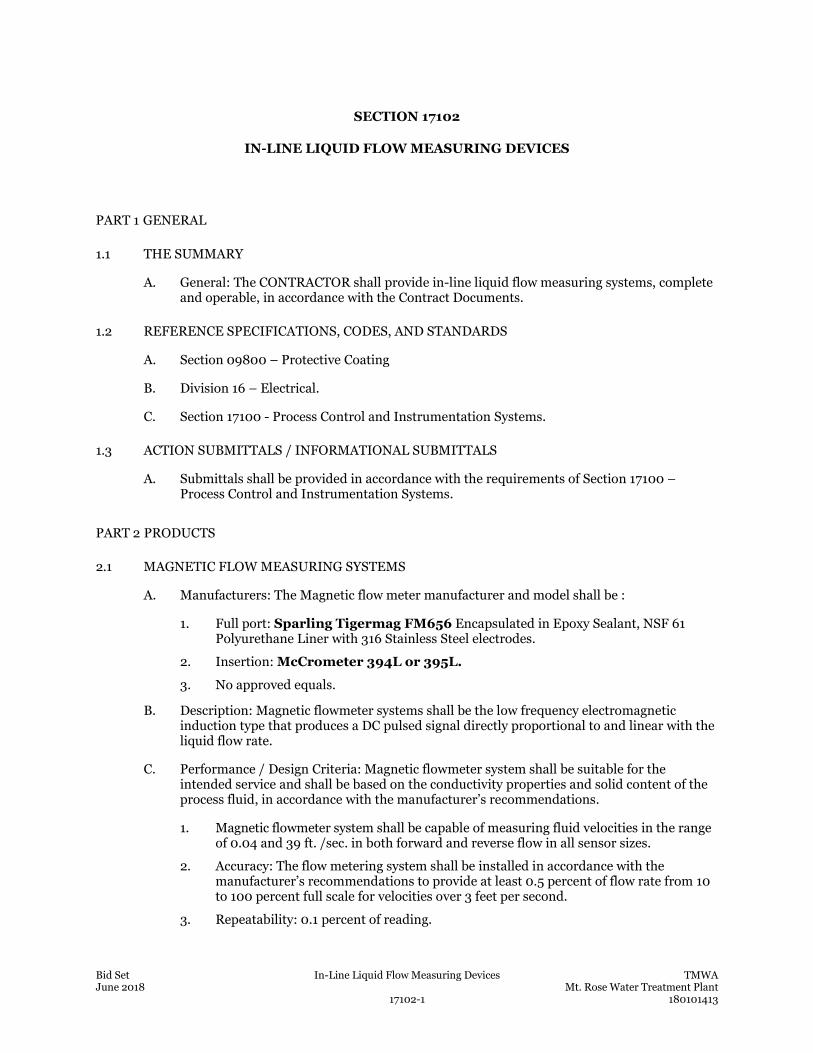
Bid Set In-Line Liquid Flow Measuring Devices TMWA June 2018 Mt. Rose Water Treatment Plant 17102-1 180101413
SECTION 17102
IN-LINE LIQUID FLOW MEASURING DEVICES
PART 1 GENERAL
1.1 THE SUMMARY
A. General: The CONTRACTOR shall provide in-line liquid flow measuring systems, complete and operable, in accordance with the Contract Documents.
1.2 REFERENCE SPECIFICATIONS, CODES, AND STANDARDS
A. Section 09800 – Protective Coating
B. Division 16 – Electrical.
C. Section 17100 - Process Control and Instrumentation Systems.
1.3 ACTION SUBMITTALS / INFORMATIONAL SUBMITTALS
A. Submittals shall be provided in accordance with the requirements of Section 17100 – Process Control and Instrumentation Systems.
PART 2 PRODUCTS
2.1 MAGNETIC FLOW MEASURING SYSTEMS
A. Manufacturers: The Magnetic flow meter manufacturer and model shall be :
1. Full port: Sparling Tigermag FM656 Encapsulated in Epoxy Sealant, NSF 61 Polyurethane Liner with 316 Stainless Steel electrodes.
2. Insertion: McCrometer 394L or 395L.
3. No approved equals.
B. Description: Magnetic flowmeter systems shall be the low frequency electromagnetic induction type that produces a DC pulsed signal directly proportional to and linear with the liquid flow rate.
C. Performance / Design Criteria: Magnetic flowmeter system shall be suitable for the intended service and shall be based on the conductivity properties and solid content of the process fluid, in accordance with the manufacturer’s recommendations.
1. Magnetic flowmeter system shall be capable of measuring fluid velocities in the range of 0.04 and 39 ft. /sec. in both forward and reverse flow in all sensor sizes.
2. Accuracy: The flow metering system shall be installed in accordance with the manufacturer’s recommendations to provide at least 0.5 percent of flow rate from 10 to 100 percent full scale for velocities over 3 feet per second.
3. Repeatability: 0.1 percent of reading.
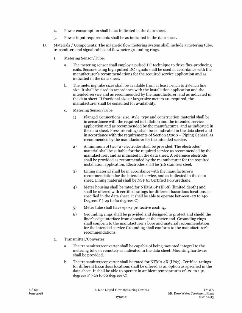
Bid Set In-Line Liquid Flow Measuring Devices TMWA June 2018 Mt. Rose Water Treatment Plant 17102-2 180101413
4. Power consumption shall be as indicated in the data sheet.
5. Power input requirements shall be as indicated in the data sheet.
D. Materials / Components: The magnetic flow metering system shall include a metering tube, transmitter, and signal cable and flowmeter grounding rings.
1. Metering Sensor/Tube:
a. The metering sensor shall employ a pulsed DC technique to drive flux-producing coils. Sensors using high pulsed DC signals shall be used in accordance with the manufacturer’s recommendations for the required service application and as indicated in the data sheet.
b. The metering tube sizes shall be available from at least 1-inch to 48-inch line size. It shall be sized in accordance with the installation application and the intended service and as recommended by the manufacturer, and as indicated in the data sheet. If fractional size or larger size meters are required, the manufacturer shall be consulted for availability.
c. Metering Sensor/Tube
1) Flanged Connections: size, style, type and construction material shall be in accordance with the required installation and the intended service application and as recommended by the manufacturer, and as indicated in the data sheet. Pressure ratings shall be as indicated in the data sheet and in accordance with the requirements of Section 15000 – Piping General as recommended by the manufacturer for the intended service.
2) A minimum of two (2) electrodes shall be provided. The electrodes’ material shall be suitable for the required service as recommended by the manufacturer, and as indicated in the data sheet. A reference electrode shall be provided as recommended by the manufacturer for the required installation application. Electrodes shall be 316 stainless steel.
3) Lining material shall be in accordance with the manufacturer's recommendation for the intended service, and as indicated in the data sheet. Lining material shall be NSF 61 Certified Polyurethane.
4) Meter housing shall be rated for NEMA 6P (IP68) (limited depth) and shall be offered with certified ratings for different hazardous locations as specified in the data sheet. It shall be able to operate between -20 to 140 Degrees F (-29 to 60 degrees C).
5) Meter tube shall have epoxy protective coating.
6) Grounding rings shall be provided and designed to protect and shield the liner's edge interface from abrasion at the meter end. Grounding rings shall conform to the manufacturer's bore and material recommendation for the intended service Grounding shall conform to the manufacturer’s recommendations.
2. Transmitter/Converter
a. The transmitter/converter shall be capable of being mounted integral to the metering tube or remotely as indicated in the data sheet. Mounting hardware shall be provided.
b. The transmitter/converter shall be rated for NEMA 4X (IP67). Certified ratings for different hazardous locations shall be offered as an option as specified in the data sheet. It shall be able to operate in ambient temperatures of -20 to 140 degrees F (-29 to 60 degrees C).
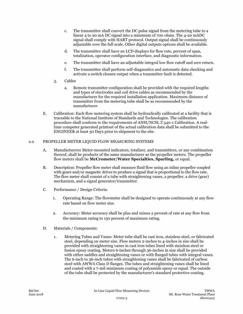
Bid Set In-Line Liquid Flow Measuring Devices TMWA June 2018 Mt. Rose Water Treatment Plant 17102-3 180101413
c. The transmitter shall convert the DC pulse signal from the metering tube to a linear 4 to 20 mA DC signal into a minimum of 700 ohms. The 4-20 mADC signal shall comply with HART protocol. Output signal shall be continuously adjustable over the full scale. Other digital outputs options shall be available.
d. The transmitter shall have an LCD displays for flow rate, percent of span, totalization, operator configuration interface, and diagnostic information.
e. The transmitter shall have an adjustable integral low flow cutoff and zero return.
f. The transmitter shall perform self-diagnostics and automatic data checking and activate a switch closure output when a transmitter fault is detected.
3. Cables
a. Remote transmitter configuration shall be provided with the required lengths and types of electrodes and coil drive cables as recommended by the manufacturer for the required installation application. Maximum distance of transmitter from the metering tube shall be as recommended by the manufacturer.
E. Calibration: Each flow metering system shall be hydraulically calibrated at a facility that is traceable to the National Institute of Standards and Technologies. The calibration procedure shall conform to the requirements of ANSI/NCSL Z 540-1 Calibration. A real-time computer generated printout of the actual calibration data shall be submitted to the ENGINEER at least 30 Days prior to shipment to the site.
2.2 PROPELLER METER LIQUID FLOW MEASURING SYSTEMS
A. Manufacturers: Meter-mounted indicators, totalizer, and transmitters, or any combination thereof, shall be products of the same manufacturer as the propeller meters. The propeller flow meters shall be McCrometer/Water Specialties, Sparling, or equal.
B. Description: Propeller flow meter shall measure fluid flow using an inline propeller coupled with gears and/or magnetic drives to produce a signal that is proportional to the flow rate. The flow meter shall consist of a tube with straightening vanes, a propeller, a drive (gear) mechanism, and a signal generator/transmitter.
C. Performance / Design Criteria:
1. Operating Range: The flowmeter shall be designed to operate continuously at any flow rate based on flow meter size.
2. Accuracy: Meter accuracy shall be plus and minus 2 percent of rate at any flow from the minimum rating to 150 percent of maximum rating.
D. Materials / Components:
1. Metering Tubes and Vanes: Meter tube shall be cast iron, stainless steel, or fabricated steel, depending on meter size. Flow meters 2-inches to 4-inches in size shall be provided with straightening vanes in cast iron tubes lined with stainless steel or fusion epoxy coating. Meters 6-inches through 36-inches in size shall be provided with either saddles and straightening vanes or with flanged tubes with integral vanes. The 6-inch to 36-inch tubes with straightening vanes shall be fabricated of carbon steel with AWWA Class D flanges. The tubes and straightening vanes shall be lined and coated with a 7-mil minimum coating of polyamide epoxy or equal. The outside of the tube shall be protected by the manufacturer's standard protective coating.
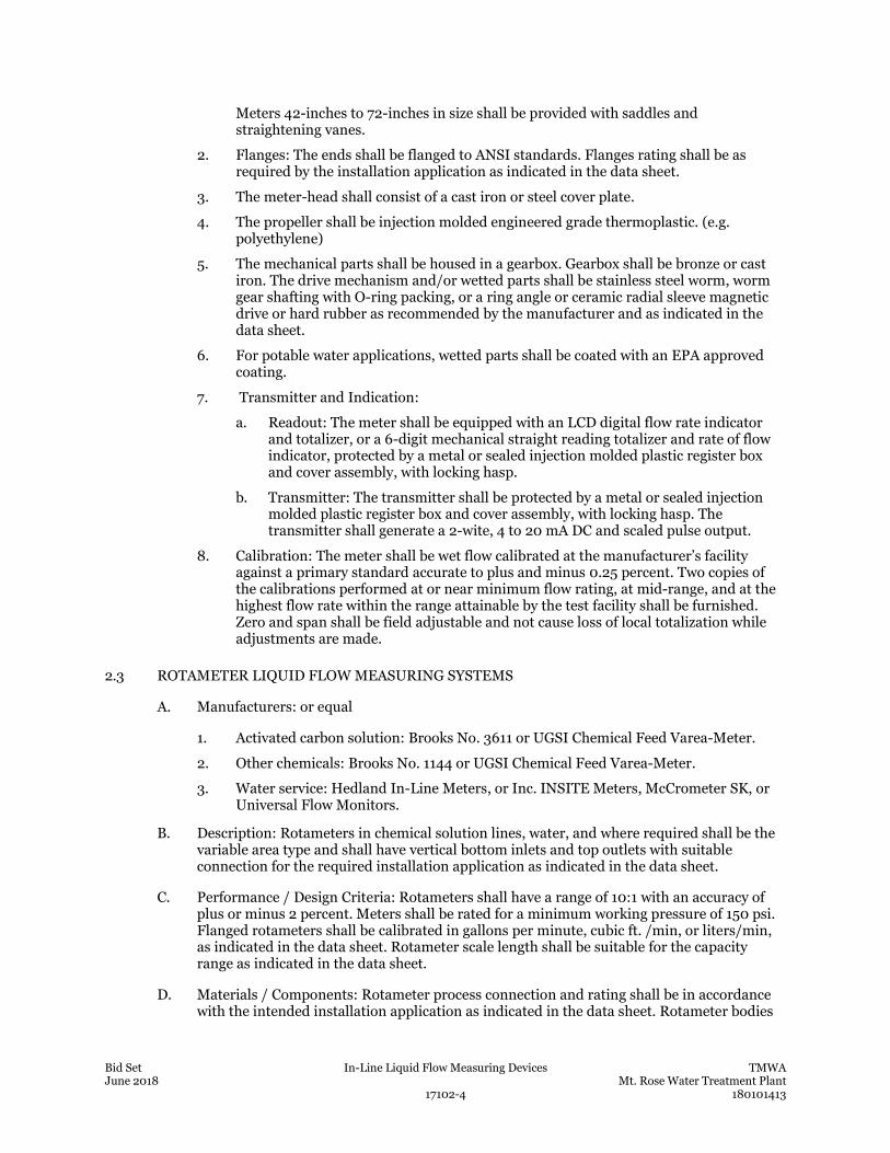
Bid Set In-Line Liquid Flow Measuring Devices TMWA June 2018 Mt. Rose Water Treatment Plant 17102-4 180101413
Meters 42-inches to 72-inches in size shall be provided with saddles and straightening vanes.
2. Flanges: The ends shall be flanged to ANSI standards. Flanges rating shall be as required by the installation application as indicated in the data sheet.
3. The meter-head shall consist of a cast iron or steel cover plate.
4. The propeller shall be injection molded engineered grade thermoplastic. (e.g. polyethylene)
5. The mechanical parts shall be housed in a gearbox. Gearbox shall be bronze or cast iron. The drive mechanism and/or wetted parts shall be stainless steel worm, worm gear shafting with O-ring packing, or a ring angle or ceramic radial sleeve magnetic drive or hard rubber as recommended by the manufacturer and as indicated in the data sheet.
6. For potable water applications, wetted parts shall be coated with an EPA approved coating.
7. Transmitter and Indication:
a. Readout: The meter shall be equipped with an LCD digital flow rate indicator and totalizer, or a 6-digit mechanical straight reading totalizer and rate of flow indicator, protected by a metal or sealed injection molded plastic register box and cover assembly, with locking hasp.
b. Transmitter: The transmitter shall be protected by a metal or sealed injection molded plastic register box and cover assembly, with locking hasp. The transmitter shall generate a 2-wite, 4 to 20 mA DC and scaled pulse output.
8. Calibration: The meter shall be wet flow calibrated at the manufacturer’s facility against a primary standard accurate to plus and minus 0.25 percent. Two copies of the calibrations performed at or near minimum flow rating, at mid-range, and at the highest flow rate within the range attainable by the test facility shall be furnished. Zero and span shall be field adjustable and not cause loss of local totalization while adjustments are made.
2.3 ROTAMETER LIQUID FLOW MEASURING SYSTEMS
A. Manufacturers: or equal
1. Activated carbon solution: Brooks No. 3611 or UGSI Chemical Feed Varea-Meter.
2. Other chemicals: Brooks No. 1144 or UGSI Chemical Feed Varea-Meter.
3. Water service: Hedland In-Line Meters, or Inc. INSITE Meters, McCrometer SK, or Universal Flow Monitors.
B. Description: Rotameters in chemical solution lines, water, and where required shall be the variable area type and shall have vertical bottom inlets and top outlets with suitable connection for the required installation application as indicated in the data sheet.
C. Performance / Design Criteria: Rotameters shall have a range of 10:1 with an accuracy of plus or minus 2 percent. Meters shall be rated for a minimum working pressure of 150 psi. Flanged rotameters shall be calibrated in gallons per minute, cubic ft. /min, or liters/min, as indicated in the data sheet. Rotameter scale length shall be suitable for the capacity range as indicated in the data sheet.
D. Materials / Components: Rotameter process connection and rating shall be in accordance with the intended installation application as indicated in the data sheet. Rotameter bodies

Bid Set In-Line Liquid Flow Measuring Devices TMWA June 2018 Mt. Rose Water Treatment Plant 17102-5 180101413
shall have union ends for ease of maintenance with, polysulphone tubes. Fittings, internal parts, and float materials shall be as recommended by the manufacturer for the intended service application and as indicated in the data sheet.
2.4 ULTRASONIC LIQUID FLOW MEASURING SYSTEMS - FIELD MOUNTED (TRANSIT TIME) – FOR USE AT RAW WATER PUMP STATION ONLY
A. Manufacturers: The flow meter manufacture shall be Flexim, Badger, GE/Panametrics, Accusonics, or Equal.
B. Description: Meters shall be directional and utilize ultrasonic velocity measurement principles. The electronic unit shall utilize information from the velocity sensing probes to accurately measure flow in the pipe. The meters shall be suitable for measuring the flow being returned to Whites Creek from the RWPS Solids Pump.
C. Performance / Design Criteria:
1. Accuracy: The meters shall have an accuracy of plus and minus 2 percent of actual flow at velocities greater than one foot per second.
2. Power Input and Consumption: Power input shall be 100 to 230 Volts, 60 Hz, or 20-32VDC; consumption shall be <10W.
D. Materials / Components: Field-mounted ultrasonic flow meters shall consist of transducers mounted as per manufacturer’s instructions. The equipment manufacturer shall select the signal and frequency for proper ultrasonic transmission. Wiring within the electronic unit shall be factory pre-wired. A local flow indicator, scaled in the indicated flow range, shall be provided in an accessible location for easy reading.
1. Transducers: transducers shall be mounted in accordance with manufacturer’s instructions. As a minimum, mounting hardware material shall be 316 stainless steel. The probes shall be fabricated of non-corrosive material and shall be equipped with an armored triaxial cable for electric transmission.
2. Transmitter: The transmitter unit shall produce a 4 to 20 mA DC signal, and a scaled pulse output signal, if totalization is indicated, proportional to the flow rate.
PART 3 EXECUTION
3.1 FIELD QUALITY CONTROL
A. In-line liquid flow measuring systems shall be handled, installed, calibrated, loop-tested, pre-commissioned, and performance tested in accordance with Section 17100 Process Control and Instrumentation Systems. Manufacturer’s service, supervision, and training shall also be in accordance with Section 17100 Process Control and Instrumentation Systems.
END OF SECTION

This page was left blank intentionally.
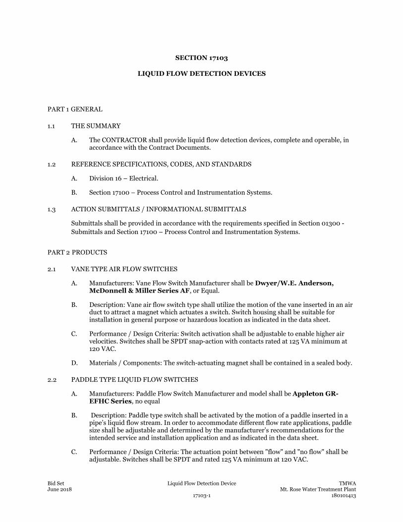
Bid Set Liquid Flow Detection Device TMWA June 2018 Mt. Rose Water Treatment Plant 17103-1 180101413
SECTION 17103
LIQUID FLOW DETECTION DEVICES
PART 1 GENERAL
1.1 THE SUMMARY
A. The CONTRACTOR shall provide liquid flow detection devices, complete and operable, in accordance with the Contract Documents.
1.2 REFERENCE SPECIFICATIONS, CODES, AND STANDARDS
A. Division 16 – Electrical.
B. Section 17100 – Process Control and Instrumentation Systems.
1.3 ACTION SUBMITTALS / INFORMATIONAL SUBMITTALS
Submittals shall be provided in accordance with the requirements specified in Section 01300 - Submittals and Section 17100 – Process Control and Instrumentation Systems.
PART 2 PRODUCTS
2.1 VANE TYPE AIR FLOW SWITCHES
A. Manufacturers: Vane Flow Switch Manufacturer shall be Dwyer/W.E. Anderson, McDonnell & Miller Series AF, or Equal.
B. Description: Vane air flow switch type shall utilize the motion of the vane inserted in an air duct to attract a magnet which actuates a switch. Switch housing shall be suitable for installation in general purpose or hazardous location as indicated in the data sheet.
C. Performance / Design Criteria: Switch activation shall be adjustable to enable higher air velocities. Switches shall be SPDT snap-action with contacts rated at 125 VA minimum at 120 VAC.
D. Materials / Components: The switch-actuating magnet shall be contained in a sealed body.
2.2 PADDLE TYPE LIQUID FLOW SWITCHES
A. Manufacturers: Paddle Flow Switch Manufacturer and model shall be Appleton GR-EFHC Series, no equal
B. Description: Paddle type switch shall be activated by the motion of a paddle inserted in a pipe’s liquid flow stream. In order to accommodate different flow rate applications, paddle size shall be adjustable and determined by the manufacturer’s recommendations for the intended service and installation application and as indicated in the data sheet.
C. Performance / Design Criteria: The actuation point between "flow" and "no flow" shall be adjustable. Switches shall be SPDT and rated 125 VA minimum at 120 VAC.
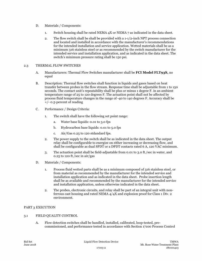
Bid Set Liquid Flow Detection Device TMWA June 2018 Mt. Rose Water Treatment Plant 17103-2 180101413
D. Materials / Components:
1. Switch housing shall be rated NEMA 4X or NEMA 7 as indicated in the data sheet.
2. The flow switch shall be shall be provided with a 1-1/2-inch NPT process connection and located and installed in accordance with the manufacturer’s recommendations for the intended installation and service application. Wetted materials shall be as a minimum 316 stainless steel or as recommended by the switch manufacturer for the intended service and installation application, and as indicated in the data sheet. The switch’s minimum pressure rating shall be 150 psi.
2.3 THERMAL FLOW SWITCHES
A. Manufacturers: Thermal Flow Switches manufacturer shall be FCI Model FLT93S, no equal
B. Description: Thermal flow switches shall function in liquids and gases based on heat transfer between probes in the flow stream. Response time shall be adjustable from 1 to 150 seconds. The contact unit’s repeatability shall be plus or minus 1 degree F. in an ambient temperature range of 25 to 120 degrees F. The actuation point shall not be affected by process fluid temperature changes in the range of -40 to 140 degrees F. Accuracy shall be +/- 0.5-percent of reading
C. Performance / Design Criteria:
1. The switch shall have the following set point range:
a. Water base liquids: 0.01 to 3.0 fps
b. Hydrocarbon base liquids: 0.01 to 5.0 fps
c. Air/Gas 0.25 to 120 stdandard fps.
2. The power supply to the switch shall be as indicated in the data sheet. The output relay shall be configurable to energize on either increasing or decreasing flow, and shall be configurable as dual SPDT or a DPDT contacts rated 6 A, 120 VAC minimum.
3. The actuation point shall be field-adjustable from 0.01 to 3.0 ft./sec in water, and 0.25 to 120 ft./sec in air/gas
D. Materials / Components:
1. Process fluid wetted parts shall be as a minimum composed of 316 stainless steel, or from material as recommended by the manufacturer for the intended service and installation application and as indicated in the data sheet. Probe insertion length shall be as available and recommended by the manufacturer for the intended service and installation application, unless otherwise indicated in the data sheet.
2. The probes, electronic circuits, and relay shall be part of an integral unit with non-ferrous cast housing and rated NEMA 4/4X and explosion proof for Class 1 Div. 2 environment.
PART 3 EXECUTION
3.1 FIELD QUALITY CONTROL
A. Flow detection switches shall be handled, installed, calibrated, loop-tested, pre-commissioned, and performance tested in accordance with Section 17100 Process Control

Bid Set Liquid Flow Detection Device TMWA June 2018 Mt. Rose Water Treatment Plant 17103-3 180101413
and Instrumentation Systems. Manufacturer’s service, supervision, and training shall also be in accordance with Section 17100 - Process Control and Instrumentation Systems.
END OF SECTION

This page was left blank intentionally.
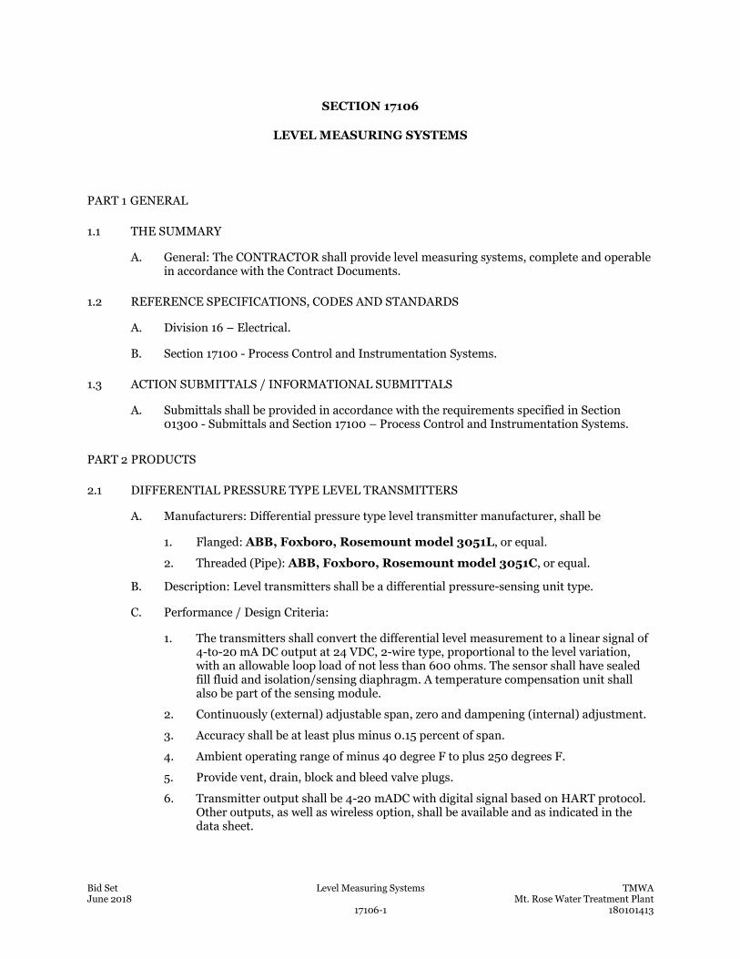
Bid Set Level Measuring Systems TMWA June 2018 Mt. Rose Water Treatment Plant 17106-1 180101413
SECTION 17106
LEVEL MEASURING SYSTEMS
PART 1 GENERAL
1.1 THE SUMMARY
A. General: The CONTRACTOR shall provide level measuring systems, complete and operable in accordance with the Contract Documents.
1.2 REFERENCE SPECIFICATIONS, CODES AND STANDARDS
A. Division 16 – Electrical.
B. Section 17100 - Process Control and Instrumentation Systems.
1.3 ACTION SUBMITTALS / INFORMATIONAL SUBMITTALS
A. Submittals shall be provided in accordance with the requirements specified in Section 01300 - Submittals and Section 17100 – Process Control and Instrumentation Systems.
PART 2 PRODUCTS
2.1 DIFFERENTIAL PRESSURE TYPE LEVEL TRANSMITTERS
A. Manufacturers: Differential pressure type level transmitter manufacturer, shall be
1. Flanged: ABB, Foxboro, Rosemount model 3051L, or equal.
2. Threaded (Pipe): ABB, Foxboro, Rosemount model 3051C, or equal.
B. Description: Level transmitters shall be a differential pressure-sensing unit type.
C. Performance / Design Criteria:
1. The transmitters shall convert the differential level measurement to a linear signal of 4-to-20 mA DC output at 24 VDC, 2-wire type, proportional to the level variation, with an allowable loop load of not less than 600 ohms. The sensor shall have sealed fill fluid and isolation/sensing diaphragm. A temperature compensation unit shall also be part of the sensing module.
2. Continuously (external) adjustable span, zero and dampening (internal) adjustment.
3. Accuracy shall be at least plus minus 0.15 percent of span.
4. Ambient operating range of minus 40 degree F to plus 250 degrees F.
5. Provide vent, drain, block and bleed valve plugs.
6. Transmitter output shall be 4-20 mADC with digital signal based on HART protocol. Other outputs, as well as wireless option, shall be available and as indicated in the data sheet.
Bid Set Level Measuring Systems TMWA June 2018 Mt. Rose Water Treatment Plant 17106-2 180101413
7. Sensor or transmitter failure alarm - High or low failure mode - shall be provided and shall be user selectable.
D. Materials / Components
1. Sensor fill fluid shall be silicon.
2. Process wetted parts and diaphragm shall be as recommended by the manufacturer for the intended service and as indicated in the data sheet.
3. As a minimum, housing material shall be 316 stainless steel or as recommended by the manufacturer for the intended service and as indicated in the data sheet. As a minimum, housing shall be rated NEMA 4X, unless otherwise indicated in the data sheet. Explosion proof rated housing shall be available.
4. Non-wetted parts, including flanges, shall be as recommended by the manufacturer for the intended service and as indicated in the data sheet.
5. Transmitter shall have an integral digital LCD indicator scaled in linear engineering units.
6. Provide transmitter mounting hardware suitable for the installation style and application.
7. Process connection style shall be 1/2-inch NPT or flange. Connection style and flange size rating and material shall suitable for the intended service and installation application as recommended by the manufacturer and as indicated in the data sheet.
8. For flanged connection, the standard flange type shall be ANSI, Class 150 psi, unless otherwise indicated in the data sheet. The low pressure connection shall be 1/2-inch NPT.
2.2 DIAPHRAGM SEALS FOR DIFFERENTIAL TYPE LEVEL MEASURING SYSTEMS
A. Manufacturers: Diaphragm seal manufacturer, shall be Rosemount 1199, or Equal.
B. Description: The diaphragm seal shall attach to the inlet connection of a level instrument in order to isolate its measuring element from the process fluid due to incompatibility and/or high process fluid temperature. The space between the diaphragm and the pressure element shall be direct mount, or completely filled with a suitable liquid. Displacement of the liquid fill in the pressure element through the movement of the diaphragm shall transmit process pressure changes directly to a gauge, transmitter, switch, or other pressure instrument.
C. Materials / Components:
1. Housing material shall be compatible with the process liquid as recommended by the manufacturer and as indicated in the data sheet.
2. Material of exposed surfaces, capillary and diaphragm shall be as recommended by the manufacturer for the intended service and as indicated in the data sheet.
3. For remote mount seal systems, a capillary shall be provided. Seal/capillary connection type and length of capillary shall be as recommended by the manufacturer for the intended installation and as indicated in the data sheet.
4. The diaphragm seal shall be factory-assemble to the corresponding pressure instrument and factory-fill. The fill liquid shall be as recommended by the manufacturer for the intended service, and as indicated in the data sheet.
Bid Set Level Measuring Systems TMWA June 2018 Mt. Rose Water Treatment Plant 17106-3 180101413
5. The diaphragm seal shall be shipped a tag reading "Do not disassemble for installation.”
6. The diaphragm seal shall be of the same manufacturer as the level transmitter.
2.3 NON-CONTACT ULTRASONIC TYPE LEVEL MEASUREMENT
A. Manufacturers: Ultrasonic level measuring systems shall be Siemens SITRANS Probe LU, no equal.
B. Description: Ultrasonic level measuring systems shall use continuous ultrasonic echo ranging technology to monitor liquid level of any consistency consist of an electronic controller-transmitter, a non-contact ultrasonic transducer, and interconnecting cables. The controller-transmitter shall generate the ultrasonic signal to drive the transducer, detect the return echo and convert the elapsed time to a level signal.
C. Performance / Design Criteria:
1. The transmitter unit shall provide an isolated 4 - 20 mADC output signal, linearly proportional to level. The output shall be compatible with HART protocol. The transmitter shall have a single or a dual point level monitoring. In addition, the transmitter shall provide up to six (6) SPDT relay outputs, rated at 5Amp.
2. The transmitter’s accuracy shall be at least 0.25-percent of span. It shall have non-interacting zero and span controls. The unit shall have a local LCD display for configuration and monitoring scalable in the desired process variable. Measuring range shall be as indicated in the data sheet.
D. Materials / Components: Transducer shall have temperature compensation and a contact output upon transmitter failure (loss of echo). Input power shall be as indicated in the data sheet. The ultrasonic transducer shall be housed in an enclosure suitable for the required installation location.
2.4 SUBMERSIBLE TRANSDUCER TYPE LEVEL MEASUREMENT
A. Manufacturers:
a. Submersible level transducers/transmitters manufacturer and model shall be GE/Druck Model PTX 1880/1885, Dwyer/Mercoid PBLT2/PBLTX Measurement Specialties, Viatran, or equal.
b. Termination enclosure manufacturer and model shall be GE/Druck model STE 110, or equal.
B. Description: The submersible level measurement system shall be designed for level and depth measurements, such as wells, where small transducer size is required. The level measurement system shall consist of a submersible transducer, electronic transmitter, support cable, and interconnecting cable with cable shield, termination enclosure, and vent tube for atmospheric reference. The installation shall allow easy removal of the transducer and cable assembly for maintenance purposes
C. Performance / Design Criteria:
a. The transducer shall be the strain gauge type suitable for sensing pressure equivalent to the measured liquid level range. Various pressure ranges shall be available from 1 to 900 psig and shall be provided as indicated in the data sheet.
Bid Set Level Measuring Systems TMWA June 2018 Mt. Rose Water Treatment Plant 17106-4 180101413
b. The transducer’ shall be less than 1-inch in diameter and shall be integral to and suspended by a corrosion resistant cable, as recommended by the manufacture
c. The transmitter shall produce a 24 VDC, 4 - 20 mA DC signal linearly proportional to the required level range as indicated in the data sheet. The measurement system shall operate over a temperature range of -5 to 140 degrees F with an accuracy of plus or minus 0.1 percent of full scale. Local indication shall be provided, unless otherwise indicated in the data sheet.
D. Materials / Components:
1. Submersible Transducer/Transmitter:
a. The wetted parts of the transducer/transmitter’s body assembly shall be as recommended by the manufacturer. The transducer/transmitter shall be provided with a lightning surge arrestor. It shall be rated IP68/Type 6. Based on installation location rating, the unit shall be intrinsically safe and rated for Class I Div. II area. Intrinsically safe barriers shall be provided as required.
b. Vent Tube: The vent tube shall be used for atmospheric reference and terminated in a sensor termination enclosure. Vent tube shall be able to support a load of up to 115 lb. and its material shall be compatible with the measured liquid level as recommended by the manufacturer for the intended service and as indicated in the data sheet.
c. Termination Enclosure: The vent tube and the pressure transducer shall be terminated in an enclosure rated for the installation location. The enclosure shall contain a replaceable desiccant module with an integral moisture status indicator, and a replaceable micro filter assembly against ingress of dust. A DIN standard terminal block shall also be included. Mounting hardware shall be included for the required installation requirements.
PART 3 EXECUTION
3.1 FIELD QUALITY CONTROL
A. Level measuring systems shall be handled, installed, calibrated, loop-tested, pre-commissioned, and performance tested in accordance with Section 17100 - Process Control and Instrumentation Systems. Manufacturer’s service, supervision, and training shall also be in accordance with Section 17100 - Process Control and Instrumentation Systems.
END OF SECTION
Bid Set Level Detection Switches TMWA June 2018 Mt. Rose Water Treatment Plant 17107-1 180101413
SECTION 17107
LEVEL DETECTION SWITCHES
PART 1 GENERAL
1.1 THE SUMMARY
A. General: The CONTRACTOR shall provide level detection switches, complete and operable, in accordance with the Contract Documents.
1.2 REFERENCE SPECIFICATIONS, CODES AND STANDARDS
A. Division 16 – Electrical.
B. Section 17100 - Process Control and Instrumentation Systems.
1.3 ACTION SUBMITTALS / INFORMATIONAL SUBMITTALS
A. Submittals shall be provided in accordance with the requirements specified in Section 01300 – Submittals and Section 17100 – Process Control and Instrumentation Systems.
PART 2 PRODUCTS
2.1 TIPPING FLOAT TYPE LEVEL SWITCHES
A. Manufacturers: Tipping float type level switch manufacturers shall be FLYGT ENM-10, KARI, MAGNETROL T10, POLYLOK, SIEMENS, SJE PUMPMASTER WPS, or equal.
B. Description: Tipping float level switch shall consist of a switch, a moving float, and a connecting cable that is anchored at the midpoint of a differential band. As the level rises and falls the float rights itself or inverts causing switching actions. The cable anchoring point shall be protected by strain relief.
C. Performance / Design Criteria: The hermetically sealed switches shall have a SPDT output with a minimum rating of 10 Amps at 120 VAC.
D. Materials / Components: The float switch shall be mercury-free. Float material shall be in accordance with the manufacturer’s recommendations for the intended service and installation application and as indicated in the data sheet.
1. Provide NSF/ANSI 61 rated switches in potable water locations.
2.2 SIDE MOUNTED FLOAT TYPE LIQUID LEVEL SWITCHES
A. Manufacturers: Shall be MAGNETROL TUFFY II, or equal.
B. Description: Liquid level switches shall be the side mounted float actuated type designed for horizontal mounting. The level switches shall be flange or threaded connection mounted
Bid Set Level Detection Switches TMWA June 2018 Mt. Rose Water Treatment Plant 17107-2 180101413
to suit field requirements. The switch shall consist of a fixed sealed reed switch actuated by magnets on the float assembly.
C. Performance / Design Criteria:
1. The float follows the liquid level as it changes causing the like poles of these magnets to repel each other causing the actuation of the switch.
2. The float switch shall have a SPDT relay output with a minimum rating of 10 Amps at 120 VAC.
D. Materials / Copmponents:
1. Switch housing, process connection and wetted materials shall be in accordance with the manufacturer’s recommendations for intended service and installation application and as indicated in the data sheet.
2. The switch enclosure shall be rated NEMA 4X or NEMA7 and provided as indicated in the data sheet.
2.3 TOP MOUNTED FLOAT TYPE LEVEL SWITCHES
A. Manufacturers: Shall be MAGNETROL T20-4 or T21-4, or equal.
B. Description: Top mounted float switches shall consist of floats, a rod, and a magnetic actuator which slides up and down in a non-magnetic guide tube. As the floats rise following the liquid level permanent magnets attached to pivoting switches shall snap against the guide when the floats push the actuator up, in turn tilting the switches. Tandem float switches shall be provided with a guide cage to stabilize the floats under turbulent conditions.
C. Performance / Design Criteria:
1. The level switches shall be flange or threaded connection mounted to suit field requirements.
2. The switches shall have DPDT vibration resistant contacts with a minimum rating of 4 Amps at 120 VAC.
D. Materials / Components:
1. Floats, trim, sleeve, and guide cage material shall be in accordance with the manufacturer’s recommendations for the application of the intended service and as indicated in the data sheet.
2. The switch enclosure shall be rated NEMA 4X and NEMA 7 and provided as indicated in the data sheet.
2.4 FLOAT OPERATED FLOOD SWITCHES
A. Manufacturers:
1. Gems LS-270 Series model #43982, no equal.
B. Description: Liquid level flood switches shall be float actuated with magnetic coupling protected by a perforated envelop enclosing the float, or employ a cylindrical float that rides loosely on a sealed guide tube. The switch assembly shall be designed for mounting on a vertical surfaced (wall) close to floor level to detect and alarm flooded facility or spills from critical tanks, valves and pipelines.
Bid Set Level Detection Switches TMWA June 2018 Mt. Rose Water Treatment Plant 17107-3 180101413
C. Performance:
1. The switch transmits float movement to a single snap-action SPDT switch mechanism rated at 10 amps at 120 VAC.
2. The switch shall be factory set for a maximum of 3/4-inch level differential for off-on control such as alarm and/or safety shutdown service. Detection of flooding level shall not exceed 2-inches.
D. Materials / Components: Level switch shall be rated NEMA 7 suitable for Division 1 hazardous locations or rated NEMA 4X for corrosive locations. Switch housing and float material shall be in accordance with the manufacturer’s recommendations for the intended service and installation application and as indicated in the data sheet.
2.5 DISPLACEMENT TYPE LEVEL SWITCHES
A. Manufacturers: Shall be Magnetrol Model A15 (Narrow Differential), or equal.
B. Description: Displacement type level switches shall be equipped with two (2) or more spring loaded displacers that are mounted in tandem on a suspension cable and are independently actuated by adjusting each displacer along the suspension cable. The displacers operation is based upon buoyancy principal. As the level rises and falls a magnetic sleeve and the spring move, which in turn activates a switch.
C. Performance / Design Criteria: Each of the 2 switches shall be factory calibrated to operate over a fixed narrow level differential band which is suitable mainly for liquid level alarm application. Switch contacts shall be SPDT with a minimum rating of 10 Amps at 120 VAC.
D. Materials / Components:
1. The level switches connection shall be a flange or threaded type mounted to suit field requirements. The flange type switch shall have a 3-inch, 150 lb. mounting flange as indicated in the data sheet.
2. Displacers and suspension cable material shall be in accordance with the manufacturer’s recommendations for the intended service and installation application and as indicated in the data sheet. The switch enclosure shall be rated NEMA 4X or NEMA 7 and provided as indicated in the data sheet.
2.6 NON-INTRUSIVE TYPE ULTRSONIC LEVEL SWITCHES
A. Manufacturers: MAGNETROL ECHOTEL 300, or equal.
B. Description: Non-intrusive sonic level switches shall consist of a transducer, transmitter/receiver, and control relays. The sonic level switch transmitter uses non-contact ultrasonic technology to measure liquid level shall generate pulses that are directed to the liquid level. The returning echo/signal shall be detected by the receiver. A microprocessor shall amplify and convert the signal into a digital representation of the distance from the reflecting surface.
C. Performance / Design Criteria:
1. Input power shall be 120 VAC.
2. An analog output of 4-20 mADC proportional to the liquid level shall be produced.
3. A minimum of two (2) SPDT gold flash relay contacts rated at 10-Amp shall be provided. The relay shall be energized when manually adjusted trip values are
Bid Set Level Detection Switches TMWA June 2018 Mt. Rose Water Treatment Plant 17107-4 180101413
exceeded. The microprocessor-based electronics shall enable user selection of range, span, set points, time delay, units of distance, and selectable failsafe mode. Relay set points shall be adjustable over the entire span without the use of reference targets.
4. Repeatability shall be 0.1-inch or less with a response time of less than one second and an accuracy of plus or minus 0.25 percent of full scale.
5. Automatic temperature compensation circuitry shall be incorporated.
D. Materials / Components: Transducer type and material shall as recommended by the manufacturer and as indicated in the data sheet. The transducer housing shall be rated NEMA 4X or NEMA 7 and provided as indicated in the data sheet. Transducer housing material shall be as recommended by the manufacturer’s recommendation and as indicated in the data sheet. Remote mounted units shall be provided with connecting cable provided by the manufacturer of the switches. Transducer housing shall be either wall or surface mounted.
PART 3 EXECUTION
3.1 FIELD QUALITY CONTROL:
A. Level detection switches shall be handled, installed, calibrated, loop-tested, pre-commissioned, and performance tested in accordance with Section 17100 - Process Control and Instrumentation Systems. Manufacturer’s service, supervision, and training shall also be in accordance with Section 17100 - Process Control and Instrumentation Systems.
END OF SECTION
Bid Set Pressure Measuring Systems TMWA June 2018 Mt. Rose Water Treatment Plant 17108-1 180101413
SECTION 17108
PRESSURE MEASURING SYSTEMS
PART 1 GENERAL
1.1 THE SUMMARY
A. General: The CONTRACTOR shall provide pressure measuring systems, complete and operable, in accordance with the Contract Documents.
1.2 REFERENCE SPECIFICATIONS, CODES AND STANDARDS
A. Division 16 – Electrical.
B. Section 17100 - Process Control and Instrumentation Systems.
1.3 ACTION SUBMITTALS / INFORMATIVE SUBMITTALS
A. Submittals shall be provided in accordance with the requirements specified in Section – 01300 and Section 17100 – Process Control and Instrumentation Systems.
PART 2 PRODUCTS
2.1 PRESSURE GAUGES
A. Manufacturers: Shall be Ametek Solfrunt Series 1900, Ashcroft 1279, or equal.
B. Performance / Design Criteria: Gauge Protection: Gauges shall be protected with the appropriate components as indicated in the data sheet.
C. Materials / Components:
1. Pressure gauges shall be 4-1/2 inches, with white laminated dials and black graduations, and have either a shatterproof glass or acrylic window as indicated in the data sheet. The gauges’ bottom connection size shall be as indicated in the data sheet.
2. Sensing element shall be bourdon tube with welded, stress-relieved joints. Sensing element material shall be as recommended by the manufacturer and as indicated in the data sheet. Gauges shall have an accuracy of plus and minus 1/2-percent of full scale.
3. Body material shall be as recommended by the manufacture and as indicated in the data sheet.
4. Gauge shall be either dry or liquid-filled as indicated in the data sheet.
5. Gauges shall be provided with a 316 stainless steel pulsation dampener (snubber), unless otherwise noted in the data sheet. The pulsating dampener shall absorb system pressure pulses.
Bid Set Pressure Measuring Systems TMWA June 2018 Mt. Rose Water Treatment Plant 17108-2 180101413
2.2 PRESSURE GAUGES - LOW-RANGE AND DIFFERENTIAL PRESSURE
A. Manufacturers:
1. Differential pressure gages manufacturer shall be Aschroft 1131 for ranges of 5-100 PSID or 1132 for ranges of 1-60 PSID, or equal.
2. Low-Range Differential Pressure Gauges
a. For non-corrosive gas service: Dwyer Series 2000 Magnehelic, or equal.
b. For non-corrosive liquid service: Dwyer Series 4000 Capsuhelic, or equal.
B. Description
1. Differential pressure gauges shall measure a differential pressure range between two independent pressure sources using a rolling diaphragm actuator to separate the high and low pressure ports. The gauges shall not be used with incompatible media.
2. Low-Range differential pressure gauges shall measure a differential pressure range between two independent pressure sources of air and non-combustible, non-corrosive, compatible gases using frictionless Magnehilic gage movement.
C. Performance / Design Criteria:
1. Differential pressure gages:
a. Differential pressure gages shall be able to measure various differential range from 0-1 psid to 0-100 psid,
b. Differential pressure gauges shall be 4-1/2 inches in diameter with white laminated dials and black graduations, and have either a shatterproof glass or acrylic window as indicated in the data sheet. The gauges’ bottom connection size shall be as indicated in the data sheet.
c. Body material and rating shall be as recommended by the manufacturer for the intended installation and service application and as indicated in the data sheet.
d. Wetted parts material shall be as recommended by the manufacturer for the intended service and installation application, unless otherwise indicated in the data sheet. Gauges shall have an accuracy of plus and minus 2-percent of full scale.
2. Low-Range Differential Pressure Gauges
a. Low-range differential pressure gages shall be able to measure various differential ranges of 0.05 inches of WC to 60 ft. of WC.
b. Body material shall be as recommended by the manufacturer and as indicated in the data sheet. Gauge design shall resist shock, vibration and over-pressure.
c. Wetted parts material shall be as recommended by the manufacturer for the intended service and installation application and as indicated in the data sheet.
d. Gauges shall be 4-inches in diameter with white laminated dials and black graduations and acrylic cover. The gauges shall have two 1/8-inch connections. Mounting orientation shall be vertical position.
2.3 ELECTRONIC GAUGE PRESSURE TRANSMITTERS
A. Manufacturers: Electronic Pressure Transmitter Manufacturer shall be Honeywell STG84L, no equal.
Bid Set Pressure Measuring Systems TMWA June 2018 Mt. Rose Water Treatment Plant 17108-3 180101413
B. Description: Gauge pressure transmitters shall measure the in-line process pressure using a sensor with sealed fill fluid and isolation/sensing diaphragm. The sensor shall convert the process pressure variations to a linear 4-to-20 mA DC output signal at 24 VDC, 2-wire type, proportional to the pressure variation, with an allowable loop load of not less than 600 ohms. A temperature compensation unit shall also be part of the sensing module.
C. Performance / Design Criteria:
1. Continuously (external) adjustable span, zero and dampening (internal) adjustment.
2. Accuracy shall be at least plus minus 0.14 percent of span.
3. Ambient operating range of minus 40oF to plus 250oF.
4. Provide vent, drain, block and bleed valve plugs.
5. Transmitter output shall be compatible with HART protocol.
6. Sensor or transmitter failure alarm - High or low failure mode - shall be provided and shall be user selectable.
D. Materials / Components
1. Sensor fill fluid shall be silicon.
2. Process wetted parts and diaphragm shall be as recommended by the manufacturer for the intended service and installation application and as indicated in the data sheet.
3. As a minimum, housing material shall be 316 stainless steel or as recommended by the manufacturer for the intended service and installation application and as indicated in the data sheet. As a minimum, housing shall be rated NEMA 4X, unless otherwise indicated in the data sheet. Explosion proof rated housing shall be available.
4. Non-wetted parts shall be as recommended by the manufacturer for the intended service and installation application and as indicated in the data sheet.
5. Transmitter shall have an integral digital LCD indicator scaled in linear engineering units.
6. Process connection style shall be ½-inch NPT or flange. Connection style and flange size rating and material shall be as recommended by the manufacturer and as indicated in the data sheet for the intended service and installation application.
7. Provide mounting hardware suitable for the intended service and installation application (e.g. surface mounting, 2-inch pipe, etc.)
2.4 DIFFERENTIAL PRESSURE TRANSMITTERS
A. Manufacturers: Pressure Transmitter Manufacturer, shall be Honeywell STD Series, no equal.
B. Description: Differential pressure transmitters shall be a differential pressure-sensing unit type. It shall be used in flow measurement applications (e.g. Venturi, orifice, etc.) and convert the differential pressure measurement to a linear signal of 4-to-20 mA DC output at 24 VDC, 2-wire type, proportional to the flow variation, with an allowable loop load of not less than 600 ohms. The sensor shall have sealed fill fluid and isolation/sensing diaphragm. A temperature compensation unit shall also be part of the sensing module.
Bid Set Pressure Measuring Systems TMWA June 2018 Mt. Rose Water Treatment Plant 17108-4 180101413
C. Performance / Design Criteria:
1. Differential pressure transmitter shall have a square root extraction capability in order to produce a 4-20 mADC output signal linear/proportional to flow.
2. Continuously (external) adjustable span, zero and dampening (internal) adjustment.
3. Accuracy shall be at least plus minus 0.10 percent of span.
4. Ambient operating range of minus 40 degree F to plus 250 degrees F.
5. Provide vent, drain, block and bleed valve plugs.
6. Transmitter output shall be compatible with HART protocol.
7. Sensor or transmitter failure alarm - High or low failure mode - shall be provided and shall be user selectable.
D. Materials / Components:
1. Sensor fill fluid shall be silicon.
2. Process wetted parts and diaphragm shall be as recommended by the manufacturer for the service intended and as indicated in the data sheet.
3. As a minimum, housing material shall be 316 stainless steel or as recommended by the manufacturer for the service and installation application intended and as indicated in the data sheet. As a minimum, housing shall be rated NEMA 4X, unless otherwise indicated in the data sheet. Explosion proof rated housing shall be available.
4. Non-wetted parts shall be as recommended by the manufacturer for the intended service and installation application and as indicated in the data sheet.
5. Each differential pressure transmitter shall be furnished with a three-valve manifold. As a minimum, the three-valve manifold housing material shall be 316 stainless steel or the same as the transmitter and as recommended by the manufacturer and as indicated in the data sheet. The wetted parts shall be as recommended by the manufacturer and as indicated in the data sheet.
6. Transmitter shall have an integral digital LCD indicator scaled in linear engineering units.
7. Process connection style shall be ½-inch NPT or flange. Connection style and flange size rating and material shall be as recommended by the manufacturer and as indicated in the data sheet for the intended service and installation application.
8. Provide mounting hardware suitable for the intended service and installation application (e.g. surface mounting, 2-inch pipe, etc.). Mounting hardware shall be suitable for the installation environment.
2.5 DIAPHRAGM SEALS FOR PRESSURE MEASURING SYSTEMS
A. Manufacturers:
1. For unfiltered and solids-containing liquids, and pulsating flow applications: Ashcroft Model 101, Marshalltown Series 225-01, U.S. Gauge (Ametek) SG, or equal.
2. For sodium hypochlorite under pressure: Ashcroft, or equal.
Bid Set Pressure Measuring Systems TMWA June 2018 Mt. Rose Water Treatment Plant 17108-5 180101413
3. For chemical solutions where breakage would not create a major shutdown: Harrington Industrial Plastics, Plast-O-Matic Valves Inc. GGS/GGSE, or equal.
B. Description: Operating Principles The diaphragm seal shall attach to the inlet connection of a pressure instrument to isolate its measuring element from the process fluid due to incompatibility and/or high process fluid temperature. The space between the diaphragm and the pressure element shall be completely filled with a suitable liquid. Displacement of the liquid fill in the pressure element through the movement of the diaphragm shall transmit process pressure changes directly to a gauge, transmitter, switch, or other pressure instrument.
C. Materials / Components:
1. Diaphragm seals shall consist of bottom housing, lower ring, diaphragm capsule, fill screw, flushing connection, and a top housing.
2. The bottom housing shall be removable in order to permit servicing. Bottom housing material shall be compatible with the process liquid as recommended by the manufacturer and as indicated in the data sheet.
3. As a minimum, top housing and bolts shall be 316 stainless steel, or as recommended by the manufacturer for the intended service and installation application and as indicated in the data sheet.
4. Diaphragm capsule material shall be compatible with the process liquid as recommended by the manufacturer and as indicated in the data sheet.
5. The diaphragm seal shall be factory-assemble to the corresponding pressure instrument and factory-filled. The space between the diaphragm and the pressure element shall be completely filled with a suitable liquid as recommended by the manufacturer for the intended service and installation application and as indicated in the data sheet.
6. Material of exposed surfaces, housings, and diaphragm shall be as recommended by the manufacturer for the intended service and installation application and as indicated in the data sheet.
7. The seal shall be provided with a ring, flushing port connection, and fill/bleed connection.
8. The diaphragm seal shall be shipped a tag reading "Do not disassemble for installation.
9. Manufacturers and models shall be as follows:
PART 3 EXECUTION
3.1 FIELD QUALITY CONTROL
A. Pressure measuring systems shall be handled, installed, calibrated, loop-tested, pre-commissioned, and performance tested in accordance with Section 17100 - Process Control and Instrumentation Systems. Manufacturer’s service, supervision, and training shall also be in accordance with Section 17100 - Process Control and Instrumentation Systems.
END OF SECTION

This page was left blank intentionally.
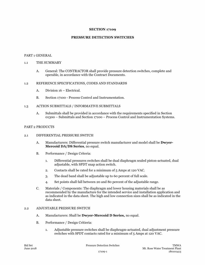
Bid Set Pressure Detection Switches TMWA June 2018 Mt. Rose Water Treatment Plant 17109-1 180101413
SECTION 17109
PRESSURE DETECTION SWITCHES
PART 1 GENERAL
1.1 THE SUMMARY
A. General: The CONTRACTOR shall provide pressure detection switches, complete and operable, in accordance with the Contract Documents.
1.2 REFERENCE SPECIFICATIONS, CODES AND STANDARDS
A. Division 16 – Electrical.
B. Section 17100 - Process Control and Instrumentation.
1.3 ACTION SUBMITTALS / INFORMATIVE SUBMITTALS
A. Submittals shall be provided in accordance with the requirements specified in Section 01300 – Submittals and Section 17100 – Process Control and Instrumentation Systems.
PART 2 PRODUCTS
2.1 DIFFERENTIAL PRESSURE SWITCH
A. Manufacturers: Differential pressure switch manufacturer and model shall be Dwyer-Mercoid DA/DS Series, no equal.
B. Performance / Design Criteria:
1. Differential pressures switches shall be dual diaphragm sealed piston-actuated, dual adjustable, with SPDT snap action switch.
2. Contacts shall be rated for a minimum of 5 Amps at 120 VAC.
3. The dead band shall be adjustable up to 60 percent of full scale.
4. Set points shall fall between 20 and 80 percent of the adjustable range.
C. Materials / Components: The diaphragm and lower housing materials shall be as recommended by the manufacture for the intended service and installation application and as indicated in the data sheet. The high and low connection sizes shall be as indicated in the data sheet.
2.2 ADJUSTABLE PRESSURE SWITCH
A. Manufacturers: Shall be Dwyer-Mercoid D Series, no equal.
B. Performance / Design Critieria:
1. Adjustable pressure switches shall be diaphragm-actuated, dual adjustment pressure switches with SPDT contacts rated for a minimum of 5 Amps at 120 VAC.
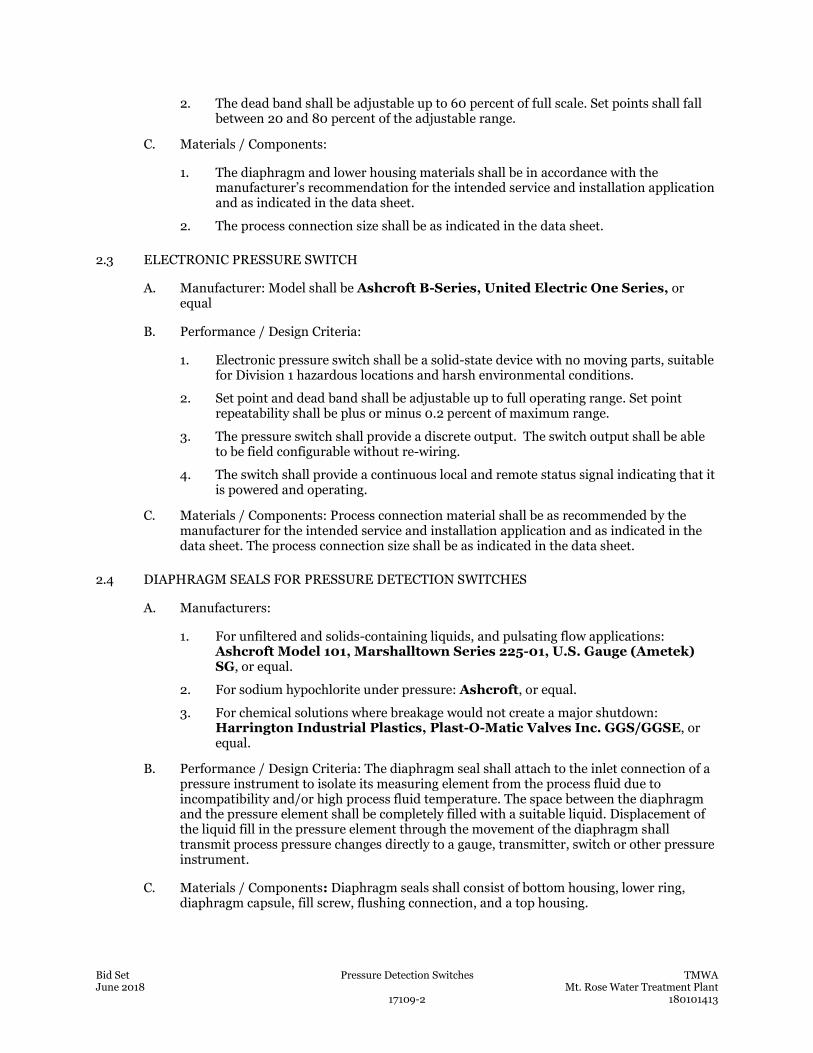
Bid Set Pressure Detection Switches TMWA June 2018 Mt. Rose Water Treatment Plant 17109-2 180101413
2. The dead band shall be adjustable up to 60 percent of full scale. Set points shall fall between 20 and 80 percent of the adjustable range.
C. Materials / Components:
1. The diaphragm and lower housing materials shall be in accordance with the manufacturer’s recommendation for the intended service and installation application and as indicated in the data sheet.
2. The process connection size shall be as indicated in the data sheet.
2.3 ELECTRONIC PRESSURE SWITCH
A. Manufacturer: Model shall be Ashcroft B-Series, United Electric One Series, or equal
B. Performance / Design Criteria:
1. Electronic pressure switch shall be a solid-state device with no moving parts, suitable for Division 1 hazardous locations and harsh environmental conditions.
2. Set point and dead band shall be adjustable up to full operating range. Set point repeatability shall be plus or minus 0.2 percent of maximum range.
3. The pressure switch shall provide a discrete output. The switch output shall be able to be field configurable without re-wiring.
4. The switch shall provide a continuous local and remote status signal indicating that it is powered and operating.
C. Materials / Components: Process connection material shall be as recommended by the manufacturer for the intended service and installation application and as indicated in the data sheet. The process connection size shall be as indicated in the data sheet.
2.4 DIAPHRAGM SEALS FOR PRESSURE DETECTION SWITCHES
A. Manufacturers:
1. For unfiltered and solids-containing liquids, and pulsating flow applications: Ashcroft Model 101, Marshalltown Series 225-01, U.S. Gauge (Ametek) SG, or equal.
2. For sodium hypochlorite under pressure: Ashcroft, or equal.
3. For chemical solutions where breakage would not create a major shutdown: Harrington Industrial Plastics, Plast-O-Matic Valves Inc. GGS/GGSE, or equal.
B. Performance / Design Criteria: The diaphragm seal shall attach to the inlet connection of a pressure instrument to isolate its measuring element from the process fluid due to incompatibility and/or high process fluid temperature. The space between the diaphragm and the pressure element shall be completely filled with a suitable liquid. Displacement of the liquid fill in the pressure element through the movement of the diaphragm shall transmit process pressure changes directly to a gauge, transmitter, switch or other pressure instrument.
C. Materials / Components: Diaphragm seals shall consist of bottom housing, lower ring, diaphragm capsule, fill screw, flushing connection, and a top housing.
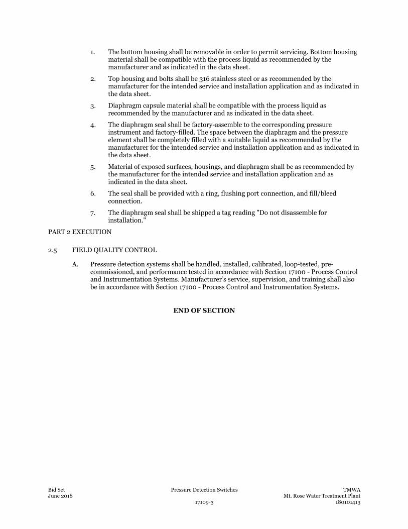
Bid Set Pressure Detection Switches TMWA June 2018 Mt. Rose Water Treatment Plant 17109-3 180101413
1. The bottom housing shall be removable in order to permit servicing. Bottom housing material shall be compatible with the process liquid as recommended by the manufacturer and as indicated in the data sheet.
2. Top housing and bolts shall be 316 stainless steel or as recommended by the manufacturer for the intended service and installation application and as indicated in the data sheet.
3. Diaphragm capsule material shall be compatible with the process liquid as recommended by the manufacturer and as indicated in the data sheet.
4. The diaphragm seal shall be factory-assemble to the corresponding pressure instrument and factory-filled. The space between the diaphragm and the pressure element shall be completely filled with a suitable liquid as recommended by the manufacturer for the intended service and installation application and as indicated in the data sheet.
5. Material of exposed surfaces, housings, and diaphragm shall be as recommended by the manufacturer for the intended service and installation application and as indicated in the data sheet.
6. The seal shall be provided with a ring, flushing port connection, and fill/bleed connection.
7. The diaphragm seal shall be shipped a tag reading "Do not disassemble for installation."
PART 2 EXECUTION
2.5 FIELD QUALITY CONTROL
A. Pressure detection systems shall be handled, installed, calibrated, loop-tested, pre-commissioned, and performance tested in accordance with Section 17100 - Process Control and Instrumentation Systems. Manufacturer’s service, supervision, and training shall also be in accordance with Section 17100 - Process Control and Instrumentation Systems.
END OF SECTION

This page was left blank intentionally.
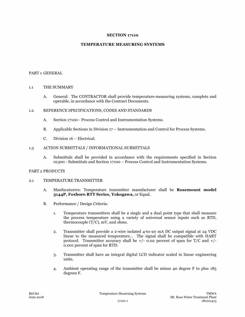
Bid Set Temperature Measruing Systems TMWA June 2018 Mt. Rose Water Treatment Plant 17110-1 180101413
SECTION 17110
TEMPERATURE MEASURING SYSTEMS
PART 1 GENERAL
1.1 THE SUMMARY
A. General: The CONTRACTOR shall provide temperature-measuring systems, complete and operable, in accordance with the Contract Documents.
1.2 REFERENCE SPECIFICATIONS, CODES AND STANDARDS
A. Section 17100 - Process Control and Instrumentation Systems.
B. Applicable Sections in Division 17 – Instrumentation and Control for Process Systems.
C. Division 16 – Electrical.
1.3 ACTION SUBMITTALS / INFORMATIONAL SUBMITTALS
A. Submittals shall be provided in accordance with the requirements specified in Section 01300 - Submittals and Section 17100 – Process Control and Instrumentation Systems.
PART 2 PRODUCTS
2.1 TEMPERATURE TRANSMITTER
A. Manfucaturers: Temperature transmitter manufacturer shall be Rosemount model 3144P, Foxboro RTT Series, Yokogawa, or Equal.
B. Performance / Design Criteria:
1. Temperature transmitters shall be a single and a dual point type that shall measure the process temperature using a variety of universal sensor inputs such as RTD, thermocouple (T/C), mV, and ohms.
2. Transmitter shall provide a 2-wire isolated 4-to-20 mA DC output signal at 24 VDC linear to the measured temperature... The signal shall be compatible with HART protocol. Transmitter accuracy shall be +/- 0.02 percent of span for T/C and +/- 0.001 percent of span for RTD.
3. Transmitter shall have an integral digital LCD indicator scaled in linear engineering units.
4. Ambient operating range of the transmitter shall be minus 40 degree F to plus 185 degrees F.
Bid Set Temperature Measruing Systems TMWA June 2018 Mt. Rose Water Treatment Plant 17110-2 180101413
C. Materials / Components:
1. Transmitter shall be connected directly to the sensor with a standard ½-inch NPT. Other connection styles shall be available and suitable for the installation requirements. Remote mounting transmitter shall also be available. Process wetted material shall be as recommended by the manufacturer for the intended service and installation application, and as indicated in the data sheet.
2. Housing shall be dual compartment made of materials recommended by the manufacturer for the intended service and installation application and as indicated in the data sheet. As a minimum, housing shall be rated NEMA 4X, unless otherwise indicated in the data sheet. Explosion proof rated housing shall be available.
3. Provide mounting hardware suitable for the installation application and style.
2.2 TEMPERATURE MEASURING SENSORS
A. RESISTANCE TEMPERATURE DETECTORS (RTD) TYPE AND THERMOWELL
1. Manfucaturers: Resistance temperature detector assemblies shall be Rosemount Series 68/78 RTD (Series 91 Thermowell), Foxboro PR Series, or equal.
2. Performance / Design Criteria:
a. The RTD shall be an industry standard Platinum-100, single element type sensor in a shield sheath. It shall be an insertion type and provided with a thermowell as an assembly from the same manufacturer. The RTD and the thermowell shall be compatible in size and connection.
b. The RTD shall be able measure temperatures from -328 to 932 Degrees F, having a maximum time constant in agitated water of 5.0 seconds. the RTD shall comply with International Practical Temperature Scale (IPTS) 90 standards
3. Materials / Components:
a. The RTD shall have a 3 or a 4-wire configuration as recommended by the manufacturer for the intended service and installation application and as indicated in the data sheet. The lead wires shall be PTFE insulated, silver plated, 22-gauge stranded copper wires. RTD extension wire shall be color-coded on the outside.
b. The RTD shall be NEMA 4X in a 1/4-inch Type 316 stainless steel sheath with watertight potting.
c. Thermowell
1) The thermowell shall be provided to protect the RTD sensor installed in the process. The thermowell insertion length shall be as required by intended service and installation application, not exceeding the manufacturer's published recommendations for the allowable length and for the line velocity and as indicated in the data sheet.
2) Standard thermowells shall be 316 stainless steel. For corrosive environments material shall be as recommended by the manufacturer for
Bid Set Temperature Measruing Systems TMWA June 2018 Mt. Rose Water Treatment Plant 17110-3 180101413
the intended service and installation application as indicated in the data sheet.
3) Thermowell style and material shall be as required by the installation application and as recommended by the manufacturer as indicated in the data sheet. Process connections shall be threaded, flanged or welded, as required by the installation application and as indicated in the data sheet. Flanged thermowells, where required, shall meet material and size requirements of the line classification
d. Connection Head: The temperature transmitter shall be connected to the RTD and thermowell assembly either directly or remotely. In remote mounting cases, the RTD/thermowell assembly shall be equipped with extension wires and a connection head. The extension wires shall be terminated in the connection head, which shall have a terminal block to accommodate single and dual sensors. The connection head shall be weather proof. Explosion proof shall be available from the manufacturer.
B. THERMOCOUPLE TYPE TEMPERATURE MEASURING SYSTEMS
1. Manfucaturers: Thermocouple assemblies shall be Rosemount Series 183 (Series 91 Thermowell), Foxboro MT Series MINOX, or equal.
2. Performance / Design Criteria: Thermocouples shall be type J, K, E or T. The junction between the wires shall be fusion welded. The junctions shall be grounded with magnesium oxide insulation to improve response time. The thermocouple shall be encased in a 304 stainless steel sheath. Thermocouple complete assembly shall be from the same manufacturer and shall include thermowell, sealed sheath element, head with block, and nipple-union-nipple fittings.
3. Materials / Components:
a. Thermocouple extension wire shall be No. 16 AWG, solid conductor, twisted pairs, shielded, with flame resistant PTFE insulation and No. 20 AWG copper drain wire attached to shield. Thermocouple extension wire shall be color-coded on the outside.
b. Thermocouples shall be able to measure temperatures up to 1,600 Degrees F. The thermocouple sensor shall be NEMA 4X.
c. Connection Head: The temperature transmitter shall be connected to the thermocouple and thermowell assembly either directly or remotely. In remote mounting cases, the thermocouple/thermowell assembly shall be equipped with extension wires and a connection head. The extension wires shall be terminated in the connection head. The connection head shall be weather proof and explosion proof.
2.3 TEMPERATURE GAUGE
A. Manfucaturers: Temperature gauges shall be by Ashcroft Series EI with thermowell, Weksler Type AF or AUW with thermowell, or equal.
B. Performance / Design Criteria:
Bid Set Temperature Measruing Systems TMWA June 2018 Mt. Rose Water Treatment Plant 17110-4 180101413
1. Temperature gauges shall be bi-metallic thermometers and shall have a 5-inch dial with a single direct-reading scale and scale as indicated in the data sheet.
2. Accuracy shall be plus or minus 1 percent of range. Each thermometer shall be provided with an appropriate thermowell in accordance with manufacturer’s recommendations.
C. Materials / Components:
1. The gauges shall be rust and corrosion-resistant with a leak-proof, hermetically sealed 316 stainless steel housing. The window shall be shatter proof glass. Process connection shall be as required by the installation application as indicated in the data sheet.
2. The sensing element shall be silicone dampened for vibration resistance. Stem length shall be the maximum standard size compatible with the piping or vessel but shall not exceed 9-inches. Dial shall be adjustable 360 degrees around the stem axis and can be tilled to 90 degrees from vertical to obtain the best viewing angle.
PART 3 EXECUTION
3.1 FIELD QUALITY CONTROL
A. Temperature measuring systems shall be handled, installed, calibrated, loop-tested, pre-commissioned, and performance tested in accordance with Section 17100 Process Control and Instrumentation Systems. Manufacturer’s service, supervision, and training shall also be in accordance with Section 17100 Process Control and Instrumentation Systems.
END OF SECTION
Bid Set Temperature Detection Switches TMWA June 2018 Mt. Rose Water Treatment Plant 17111-1 180101413
SECTION 17111
TEMPERATURE DETECTION SWITCHES
PART 1 GENERAL
1.1 THE SUMMARY
A. General: The CONTRACTOR shall provide temperature detection switches, complete and operable, in accordance with the Contract Documents.
1.2 REFERENCE SPECIFICATIONS, CODES AND STANDARDS
A. Division 16 – Electrical.
B. Section 17100 - Process Control and Instrumentation Systems.
1.3 ACTION SUBMITTALS / INFORMATIONAL SUBMITTALS
A. Submittals shall be provided in accordance with the requirements specified in Section 01300 and Section 17100 – Process Control and Instrumentation Systems.
PART 2 PRODUCTS
2.1 CAPILLARY TEMPERATURE DETECTION SWITCH
A. Manufacturers: Capillary temperature detection switches shall be Dwyer/Mercoid Series DA-7035, Ashcroft LTA, or equal.
B. Description: Temperature sensing shall utilize a Scientific Apparatus Makers Association (SAMA) Class II vapor pressure thermal system. The temperature sensor shall be either rigid, direct mounting type or remote mount type utilizing armored stainless steel capillary, as required and recommended by the manufacturer for the specific service and installation application and as indicated in the data sheet.
C. Performance / Design Criteria: Switch shall have an adjustable dead band. Switch set point repeatability shall be no more than plus or minus one percent of span and dead band shall be adjustable plus or minus 18 degrees F. The switch mechanism shall be hermetically-sealed, SPDT type, rated 5 amperes at 120 VAC. Switch shall be rated NEMA 4 and 4X. Terminal blocks shall be provided for external wiring.
D. Materials / Components: Unless otherwise indicated in the data sheet pr manufacturer’s recommendations, the complete thermal system shall be 316 stainless steel and the minimum bulb length shall be 3-inches. The temperature switch shall be provided with Type 316 stainless steel thermowell and bushing suitable for the thermal sensor. Thermowells shall have a minimum wall thickness between bore and outside of well of 3/16 inch. Thermowell insertion length shall be as recommended by the manufacturer and as
Bid Set Temperature Detection Switches TMWA June 2018 Mt. Rose Water Treatment Plant 17111-2 180101413
indicated in the data sheet for each specific service and installation application so as not to exceed the manufacturer's published allowable length/line velocity recommendations.
2.2 BIMETALLIC TEMPERATURE DETECTION SWITCHES
A. Manufacturers: Bimetallic temperature detection switches shall be Dwyer/Mercoid Series M-51 (air service), Dwyer/Mercoid Series FM-437 (water and oil service), Honeywell, or equal.
B. Performance / Design Criteria: Temperature switches shall employ a bimetal element suitable to detect air, water or oil temperature. The switch shall have a thermowell using 3/4-inch NPT process connection or flange per applicable piping code. Switches shall be provided with an adjustable setpoint, and have SPDT contacts rated at 10 Amp, 120 VAC. Switch reset shall be either automatic or manual based on the intended service and installation application as indicated in the data sheet.
PART 3 EXECUTION
3.1 FIELD QUALITY CONTROL
A. Temperature detection switches shall be handled, installed, calibrated, loop-tested, pre-commissioned, and performance tested in accordance with Section 17100 - Process Control and Instrumentation Systems. Manufacturer’s service, supervision, and training shall also be in accordance with Section 17100 - Process Control and Instrumentation Systems.
END OF SECTION
Bid Set Process Analysis Measuring Systems TMWA June 2018 Mt. Rose Water Treatment Plant 17112-1 180101413
SECTION 17112
PROCESS ANALYSIS MEASURING SYSTEMS
PART 1 GENERAL
1.1 THE REQUIREMENT
A. Provide all process sensors and analyzers/controllers, complete and operable, in accordance with the Contract Documents.
1.2 RELATED WORK AND REQUIREMENTS SPECIFIED ELSEWHERE
A. Division 16 – Electrical.
B. Section 17100 - Process Control and Instrumentation Systems.
1.3 ACTION SUBMITTALS / INFORMATIONAL SUBMITTALS
A. Provide submittals in accordance with the requirements specified in Section 01300 and Section 17100 – Process Control and Instrumentation Systems.
PART 2 PRODUCTS
2.1 GENERAL
A. Power as indicated in the data sheet.
B. Sensor Type
1. In-line style sensors:
a. Provide insertion mount fittings (isolation valve, restraining chain, insertion sleeve) for removal from the process stream without requiring production shutdown.
b. Provide continuous automatic analysis of the parameter.
c. Shall not introduce a reagent, electrolyte, or buffer into the process water.
2. By-pass style sensors:
a. Provide inlet isolation valve, flow regulating valve, overflow, drain valve, connecting tubing.
b. Provide automatic analysis of the parameter once each three (3) minutes, or better.
c. By-pass sensors shall release all sample water to a waste connection.
C. Temperature conditions:
1. Ambient operating temperatures between -20°F and 120°F.
2. Fluid temperatures between 32°F and 100°F.
Bid Set Process Analysis Measuring Systems TMWA June 2018 Mt. Rose Water Treatment Plant 17112-2 180101413
D. Relative humidity from 5 to 95 percent, non-condensing.
E. Use manufacturer’s mounting and connection hardware suitable for panel/wall mount installation.
F. All sensors measuring the same parameter shall be from a single manufacturer.
G. Provide maintenance kit with spare parts and consumables suitable for one (1) year of all service as recommended by the manufacturer.
H. Supply manufacturer’s recommended cables for connection of sensors and analyzer/controller, with a minimum of 25% spare cable length, or 5 feet, whichever is greater.
I. Converted output from each sensor shall be displayed in appropriate units on a analyzer/controller within 20 horizontal feet of the sample location.
2.2 PH SENSOR
A. Suitable for in-line determination of pH in water.
B. Requirements:
1. Shall be selective of only the hydrogen ion.
2. Use a double-junction differential electrode measurement technique, which incorporates an internal reference electrode with standard reference buffer solution, a glass pH electrode and a fouling-resistant reference electrode. The pH sensor shall have a double reference electrode design.
3. Electrodes enclosed in chemical-resistant housing suitable for the intended service application.
4. Automatic temperature compensation with replaceable salt bridge.
5. Rated for operating pressure to 300 psi.
6. Suitable for submersible applications.
7. 0 to 14 pH units measuring range with an accuracy ± 0.02 pH units.
C. Manufacturer:
1. Rosemount pH/ORP 1056 sensor, no equal.
2.3 TEMPERATURE SENSOR
A. Suitable for in-line measurement of water temperature.
B. Requirements:
1. Resistance temperature detection (RTD) for measurement
2. Single element, 3-wire device
3. Rated for operating pressure to at least 300 psi.
4. Suitable for submersible applications.
5. Operating range -40°F to 180°F with an accuracy ± 0.1°F.
C. Manufacturer
Bid Set Process Analysis Measuring Systems TMWA June 2018 Mt. Rose Water Treatment Plant 17112-3 180101413
1. Rosemount, 214C RT B1 Temperature Sensor
2. Approved equals
2.4 HIGH RANGE TURBIDITY SENSOR
A. Suitable for by-pass measurement of turbidity in Nephelometric Turbidity Units (NTU) from raw water.
B. Requirements:
1. Standardization kit with 0-100 and 0-1000 NTU range plates for calibration verification.
C. Manufacturer
1. HACH Solitax Series, no equal.
2.5 LOW RANGE TURBIDITY SENSOR
A. Suitable for by-pass measurement of turbidity in Nephelometric Turbidity Units (NTU) from filtered water.
B. Requirements:
1. Calibration unit ICE-PIC Calibration/Verification module (52250-00)
C. Manufacturer
1. HACH Model 1720E, no equal.
2.6 CHLORINE RESIDUAL SENSOR
A. Suitable for by-pass measurement of free chlorine in mg/L using the N, N-diethyl-p-phenylenediamine (DPD) method.
B. Requirements:
1. 1-year maintenance kit (5444300)
2. Sample inlet flow meter (4643600)
3. Calibration/verification kit (5449000)
4. Free chlorine reagent set (2556900)
5. DPD indicator powder (2297255)
C. Manufacturer
1. HACH Model CL17 (5440001), no equal.
2.7 STREAMING CURRENT MEASUREMENT SENSOR
A. Suitable for by-pass measurement of streaming current potential in water.
B. Requirements:
1. -1000 to +1000 range
Bid Set Process Analysis Measuring Systems TMWA June 2018 Mt. Rose Water Treatment Plant 17112-4 180101413
2. 4-20mA signal output
3. 0.2 to 10 gpm inlet flow rate
4. Automatic sensor flush
5. Manufacturer
a. Chemtrac DuraTrac4
b. Approved equals
2.8 UV TRANSMITTANCE SENSOR
A. Suitable for by-pass measurement of ultraviolet transmittance at 254 nm in water.
B. Requirements:
1. 4-20 mA signal output
C. Manufacturer
1. HACH UVAS plus sc Bypass Sensor, no equal.
2.9 ANALYZER/CONTROLLER
A. Suitable for receipt of input signals from multiple sensors within a local instrument cluster.
B. Requirements:
1. Capacity for receipt of at least 10 analog inputs. Each analyzer/controller shall accommodate multiple sensors.
2. Transmission of all outputs to plant PLC.
3. Display of converted inputs in appropriate units for each sensor on LCD touch screen
4. Uses a menu-driven operation system and an auto-ranging digital LCD display.
C. Manufacturer
1. Hach SC1000, no equal.
PART 3 EXECUTION
3.1 GENERAL
A. Process monitoring systems shall be handled, installed, calibrated, loop-tested, pre-commissioned, and performance tested including manufacturer’s service, supervision, and training in accordance with Section 17100 Process Control and Instrumentation Systems.
END OF SECTION
Bid Set Control Panels TMWA June 2018 Mt. Rose Water Treatment Plant 17200-1 180101413
SECTION 17200
CONTROL PANELS
PART 1 GENERAL
1.1 THE SUMMARY
A. General: The CONTRACTOR through the use of the System Supplier shall provide control panels for the PCIS, complete and operable, in accordance with the Contract Documents.
B. The System Supplier shall be responsible for selecting, sizing, and providing the correct and necessary type and quantity of the panels for each process control application. The necessary hardware and responsibilities shall include but not limited to:
1. Mounting the panel
2. Locating and mounting interior and exterior instruments, hardware and equipment in the panel
3. Field interface terminal blocks
4. Terminating panel internal wiring and signals
5. Terminating communication and network cabling and wiring
1.2 REFERENCE SPECIFICATIONS, CODES, AND STANDARDS
A. Division 16 – Electrical
B. Section 17100 - Process Control and Instrumentation
C. Section 17510 – PLC- Based Control System Hardware
D. The provisions of this Section apply to local panels provided in equipment systems specified in other sections unless indicated otherwise in those sections.
E. Each control panel, including panels for service entrance equipment, shall meet all UL listing and labeling requirements including UL Standard 508 and UL Standard 508A and shall be UL labeled accordingly. Contractor shall arrange components and wiring to meet UL requirements stated above.
1.3 ACTION SUBMITTALS / INFORMATIONAL SUBMITTALS
A. The Submittals shall be provided in accordance with the requirements specified in 01300 – Submittal and Section 17100 – Process Control and Instrumentation System.
1.4 QUALITY ASSURANCE
A. In accordance with Section 17100 – Process Control and Instrumentation Systems.
1.5 WARRANTY
A. In accordance with Section 17100 - Process Control and Instrumentation Systems.
Bid Set Control Panels TMWA June 2018 Mt. Rose Water Treatment Plant 17200-2 180101413
PART 2 PRODUCTS
2.1 GENERAL
A. All PCIS control panel assemblies, such as new PLCs, remote I/Os, analyzer systems, communication systems, etc. shall be mounted inside a new outdoor or indoor NEMA-rated type enclosure, suitable and designed for the application for which it was intended, as specified or as shown on the drawings. If required, PCIS panel assemblies shall be mounted in existing enclosures. Control panels shall be either freestanding, pedestal-mounted or equipment skid-mounted.
B. The enclosure and back panel shall be sized to contain the equipment required to make the installation complete and suitable for its intended purpose. Field conditions and the guidelines provided in the specifications and/or the drawings shall be followed. Accessibility for ease of maintenance, future expansion and good installation and industry practices shall be considered when sizing an enclosure. Spare space shall be kept clear of wiring, etc., to give contiguous clear space for future additions.
C. In cases where existing panel is used, the CONTRACTOR shall review the available space in the field or in the existing panel to determine the proper size of back panel suitable to accommodate the required equipment for the facility. It should be noted that control panel layouts shown on the Drawings are diagrammatic. The control panel submittal shop drawing shall reflect the accurate layout of the equipment in the panel.
D. Environmental Suitability and NEMA Rating
1. Indoor and outdoor control panels and instrument enclosures shall be suitable for operation in the ambient conditions associated with the locations designated in the Contract Documents. Heating, cooling, and dehumidifying devices shall be provided in order to maintain instrumentation devices 20-percent within the minimums and maximums of their rated environmental operating ranges. The CONTRACTOR shall provide power wiring for these devices. Enclosures shall be suitable for the environment that they are installed. Panel instruments and equipment in hazardous areas shall be suitable for use in the particular hazardous or classified location in which it is to be installed.
2. Control panels shall be sized to adequately dissipate heat generated by equipment mounted in or on the panel.
3. NEMA Rating
a. All PCIS panel assemblies, such as PLCs, remote I/Os, analyzer systems, communication systems, etc. shall be mounted in a NEMA-rated type enclosure suitable for the environment that it is located. Different NEMA rated enclosures and suitable materials of construction (e.g. stainless steel, fiberglass, etc.) shall be used for specific applications, project requirements and for corrosive and/or hazardous environments.
b. In areas that are classified as general purpose, the minimum rating of all outdoor mounted panels shall be NEMA 4 (IP66) steel construction. The minimum rating of all indoor mounted enclosures in general purpose classified areas shall be NEMA 4 or NEMA 12 (IP52) steel construction, unless otherwise indicated.
2.2 CONSTRUCTION
A. Material and Fabrication
Bid Set Control Panels TMWA June 2018 Mt. Rose Water Treatment Plant 17200-3 180101413
1. Wall mounted type enclosure shall be constructed of a minimum of 16-gauge, 14-gauge or 12-gauge steel, depending of the size of the enclosure, application, environment, and the project requirements. Floor mounted free standing enclosures shall be made of 12-gauge steel, depending of the size of the enclosure, application, and the project requirements.
2. Seams shall be continuously welded and ground smooth. Corners shall be welded and ground smooth.
3. Each enclosure shall have a heavy gauge, continuous piano hinge pin which shall support each door.
4. Door and body stiffeners shall be provided where required. The stiffeners shall be welded to the inside of enclosures to prevent deformation due to the weight of face-mounted instruments.
5. Doors shall be sealed with a closed cell neoprene gasket.
6. The interior rear and sides of each enclosure shall have steel mounting channels for supporting mounting panels.
7. Enclosures shall be provided with external mounting feet as shown, as well as door clamps, hasp and staple for padlocking, data pocket, and closed-cell oil-resistant gasket. Removable lifting lugs to facilitate handling shall be provided on large enclosures.
B. Back and Side Panels: Each enclosure shall be provided with a removable back panel. Depending on the size of the enclosure more than one back panel may be required. Removable side panels shall be provided as required for additional mounting space.
C. Finish: Non-stainless steel enclosures shall have an ANSI 61 gray polyester urethane powder coating electrostatically applied to inside and outside surfaces. Enclosure interior, and back and side panels shall be white.
D. Ventilation, Louvers, Vents, and Filters: In enclosures where excessive internal heat or internal moisture is a problem, the enclosure shall be equipped with louvers with filters and a cooling fan. The perimeters of the louver plate shall be sealed with a gasket. Louver shall be of the same material and finish as the enclosure. The louver shall be sized for effective heat rejection.
E. Accessories: The CONTRACTOR shall provide additional panel accessories to meet the specifications, such as floor stand and mounting kits, door handle and lock kits (common key shall be provided for all doors), 3-point latch, etc.
F. Instruments Mounting
1. Equipment mounted at the rear of enclosure shall be installed to allow for commissioning adjustments, operation and servicing requirements. The CONTRACTOR shall arrange components and wiring to meet UL requirements.
2. Spare space shall be kept clear of wiring, etc., to give maximum space for future additions.
3. For front mounted hardware, cutouts and holes may be cut or drilled by any standard method that does not cause deformation. Burrs shall be ground smooth. Mounting the instruments shall not degrade the NEMA rating of the enclosure.
4. DIN rail mounted equipment shall be used as much as possible.
5. Each enclosure shall be provided with interior nameplates to identify equipment tags and functions.
Bid Set Control Panels TMWA June 2018 Mt. Rose Water Treatment Plant 17200-4 180101413
G. Enclosures shall be Saginaw, Hoffman, no equal.
2.3 ELECTRICAL REQUIREMENTS
A. The main power supply to the control panel controls shall be 120 VAC, 60 Hz. The CONTRACTOR shall provide the main power supply from an external source. The CONTRACTOR shall provide a step-down transformer as required to power the panel.
B. The CONTRACTOR shall provide wireways, wire, and electrical fittings and components for 120V and 24VDC circuits to instruments and other electrical devices in the panel for a complete and operable installation. Wiring methods and materials for all panels shall be in accordance with the NEC requirements.
C. The circuits for 24VDC shall run in separate wireways from the 120 VAC circuits.
D. Each source of foreign voltage shall be isolated by providing disconnecting or pull-apart terminal blocks. Each control panel shall be provided with identified terminal strips for the connection of all external foreign voltage. A “CAUTION- Foreign Voltage” nameplate shall be attached to the outside of the enclosure door warning of foreign voltages inside the enclosure.
E. If required by the contract documents, the control panel shall be the source of power for any 120 VAC solenoid valves interconnected with the control panel.
F. Terminal Blocks
1. The control panel shall be provided with sufficient terminal blocks for the connection of external field conductors, signals, and power and for use inside the panel for power distribution and for future expansion. In order to facilitate easy and safe loop maintenance, each analog input loop shall have a disconnect with test plugs built into its field terminal block.
2. Spare Terminal Blocks for Signals: The CONTRACTOR shall provide sufficient spare terminal blocks to connect additional signals for future use (implemented and future spares). Implemented spare signals shall be wired to terminal blocks and the percent of these terminals shall be in accordance with the growth requirements specified in Section 17510 – PLC-Based Control System Hardware. For future signals (i.e. the source of inputs or final control elements are not yet known or available in the field), the CONTRACTOR shall provide 20-percent spare terminals in the panel for each type of actual I/O in the PLC. The number of terminals shall take in account the types of I/O for which spares are provided (Three (3) terminal for each AI or AO shall be provided).
3. Spare Terminal Blocks for Power and Other Applications: In addition to the spare terminals for signals, The CONTRACTOR shall provide spare terminals for 3 additional power distribution and grounding applications circuits.
4. Terminal blocks for all wiring shall be modular terminals, DIN rail mounted type rated at 15 amperes at 600 VAC and have a minimum width of 8-mm suitable for No. 12 AWG stranded wire. Terminals shall be the solderless box lug type with pressure plates in actual contact with the wire to minimize wire breakage. Each terminal shall have a light colored strip for marking the terminal number or circuit designation. Double high terminal blocks are not acceptable.
5. External connections to and from enclosures shall terminate on terminal blocks, except approved communication and data cables. Circuit isolating switches and fuse terminals shall include non-conducting pullers which can be removed with finger
Bid Set Control Panels TMWA June 2018 Mt. Rose Water Treatment Plant 17200-5 180101413
alone, without tools. Additionally, the panel shall be provided with identified terminal strips for the connection of external/field conductors.
6. Terminals shall be as manufactured by Phoenix Contact, no equal.
G. Electrical Hardware Accessories: The control panel shall be equipped with the following:
1. A duplex 15 amp, 120 VAC GFCI type receptacles for service and maintenance use. The receptacle shall be 2-pole, 3-wire grounding, and heavy duty industrial grade by Hubbell, Leviton, or equal.
2. A duplex 15-amp 120 VAC GFCI type receptacle dedicated for a powering an uninterruptible power supply (UPS). The receptacle shall be color coded, 2-pole, 3-wire grounding, heavy duty industrial grade by Hubbell, Leviton, or equal
3. A 24 VDC LED light strip lamp with guards and a toggle switch (Hoffman, Saginaw, or equal) mounted on the top of the enclosure or on the part the side or back panel shall be provided for panel lighting. A separate fuse/circuit breaker shall be provided for the lamp mounted inside and in the top of the back-of-panel area. Control panels that are longer than 72-inches, two lamps shall be provided.
4. A ¼-inch by one (1)-inch copper grounding bus bar with multiple connecting terminals. The grounding bus shall be complete with solderless connector for one 4 AWG bare stranded copper cable and with tapped holes to accommodate ground connections from various devices in the enclosure. Provide ground connections for different AWG wires and shield connection clamps by Phoenix Contact, or equal. Provide separate ground buses for analog and discrete/digital signals. The copper cable shall be provided by the CONTRACTOR and be connected to a system ground loop.
H. Circuit Breakers, Fuses, and Disconnects
1. Circuit breakers, fuses and disconnects shall be installed in the control panel to protect against fault current the 120 VAC and 24 VDC branch circuits and the instruments and the electrical components that these circuits power. Circuit breakers shall be installed as disconnects of external power feeds for control circuits from outside the enclosure and branch circuits within the enclosure.
2. The circuit breakers, fuses and disconnects shall also allow disconnecting the power from these instruments in a safe manner. Individual plug and cord set power supply connections, such as for a UPS, may be used without switches. Each circuit breaker and fuse shall be identified by a service nametag.
3. The fuses shall be mounted in a DIN mounted fuse holder terminal block and shall have a blown fuse indicator light. The fuse holders for 120 VAC applications shall have a neon light indicator and shall Phoenix Contact, no equal. The holders for 24 VDC applications shall have an LED indicator light and shall be Phoenix Contact, no equal.
4. The number of power distribution circuits depends on the type of electrical devices they power. A 120 VAC, 60 Hz single pole circuit breakers or a fuse, as noted, with the following minimum rating shall be provided in each branch circuit as listed below. The circuit load shall not exceed 10-amp. The circuit breakers shall be DIN rail mounted type. The 120 VAC breakers shall by Square D model 60112, depending on the amperage rating, no equal.
a. 20-amp main circuit breaker for the 120 VAC control panel power supply and the distribution of the power.
Bid Set Control Panels TMWA June 2018 Mt. Rose Water Treatment Plant 17200-6 180101413
b. 15 amp circuit breaker for the duplex 15 amp, 120 VAC GFCI type receptacle used for service and maintenance.
c. 15-amp circuit breaker (or as required by the UPS manufacturer) for the dedicated duplex GCFI type receptacle used for the UPS.
d. 5-amp fuse, 120 VAC for each of the 120 VAC power input circuits to the two (2) redundant 24 VDC power supplies.
e. A 1/8 – amp fuse to protect the 24 VDC LED light.
f. A fuse, sized as required, shall be provided for the protection of each 24 VDC branch (including spares) and equipment that is powered by the 24 VDC power supply. Each analog and discrete input loop shall also be protected by a fuse. A fuse shall be provided to each instrument regardless if it is equipped with integral replaceable fuse.
I. Uninterruptible Power Supply
1. The CONTRACTOR shall provide an uninterruptible AC power supply (UPS) system for each control panel to back up the power for the panel in case utility power fails. The UPS shall be a “smart” type, use on-line, high frequency, double-conversion technology. The batteries shall be integral to the UPS enclosure
2. Capacity and Duration: The continuous output capacity of the UPS shall be at least 1,000 VA. It shall be sufficient to supply the computers, interface and peripheral equipment (present and future) with regulated AC power for a minimum of one (1) hour from batteries only. Additional batteries or larger UPS size shall be provided to meet the specified backup time.
3. The CONTRACTOR shall submit load calculations and size each UPS to justify the selection of present and future load requirements, as well as overload and inrush capacity requirements.
4. Under normal conditions the AC power line shall feed the UPS to power the protected load. The UPS shall also maintain the batteries in fully charged “float” condition. Whenever the normal AC power fails or dips below the normal range, the critical load shall be continuously supplied from the batteries and the double conversion system. The transfer from normal to AC line to backup power shall be bumpless and without a break in the output of the UPS (0 transfer time).
5. Features and Options
a. Input Power Range: 100 to 132 volts, 60 Hertz +/- 5 Hertz, auto-sensing.
b. Output Power Range: 110/120 (selectable), +/- 3 percent of nominal, 60 Hertz +/- 0.5 percent.
c. Output Receptacles: Minimum of six (6) built-in outlets.
d. Overload Capacity: The UPS shall have the ability to supply 110 percent of system requirements for 10 seconds, without degradation of the service life.
e. Protection: The UPS output shall be protected (IEEE standards) from lightning, surges overload, and short circuit. The input shall be protected by a circuit breaker, sized in accordance with manufacturer’s recommendations.
f. Battery: Lead acid type, maintenance free, sealed suspended electrolyte, and leak-proof. Recharge Time (with half load): three (3) hours.
g. Alarms and Status: The UPS shall be provided with a relay output card in a combination with a network management card (NMC) to provide a common dry contact output that represents the health/status of the UPS and battery
Bid Set Control Panels TMWA June 2018 Mt. Rose Water Treatment Plant 17200-7 180101413
functions (i.e. low battery, UPS on batteries, UPS fault, batteries failed on battery self-test). The NMC shall be configured to provide the above alarms/status listed above.
6. Manufacturer: Schneider Electric-APC model Smart-UPS SMT – 1,000VA LCD, with AP9631 Network Management Card and AP9810 relay output card, no equal.
J. Control Panel 24 VDC Power Supplies
1. Control panels shall be provided with redundant power supplies which shall be configured in a fault-tolerant manner to prevent interruption of service upon failure and interruption of service necessitated by the replacement of a power supply.
2. The CONTRACTOR shall size the power supplies to meet the control panel requirement and the instruments and loops they support. Power supplies shall have an excess rated capacity of 40 percent. The failure of a power supply shall be alarmed at the SCADA System.
3. Power Supplies – 24 VDC: The control and PLC panels shall be the source of power for any 24 VDC two-wire field device, devices in the panel requiring 24 VDC power, or where applicable, solenoid valves interconnected with the panel.
4. The failure of a power supply shall generate a dry relay contact output that can be used as an input to the PLC/ SCADA system.
5. Power supplies shall be Power Sonic PS 1270, no equal.
K. Control Panel Signal, Control and Power Wiring
1. General: The signal, control and power wiring specified herein shall apply only to the wiring inside the control panel. Field wiring shall be in accordance with requirements specified in Division 26.
2. Wire type and sizes: Conductor shall be flexible, stranded, copper UL approved type wires, and shall be rated 600 volts. The following wire sizes and insulation types and color shall be used inside the control panel for the listed applications:
a. 120 VAC power wires: Main 120 VAC power wiring for distribution in the control panel (line, neutral and ground) shall be a minimum of 12 AWG, or heavier as required by the panel load, with THHN/THWN insulation.
b. Power conductors in branch circuits such as for lighting, receptacle, heater and thermostat, etc. shall be a minimum of 14 AWG also with THHN/THWN insulation.
c. Wiring for 600 volt class power and lighting shall be as manufactured by General Cable, Okonite, Southwire, or equal.
d. The following insulation color code designation shall be used:
1) Line Power – Black
2) Neutral (grounded circuits) – White
3) Power Ground – Green
4) Ungrounded 120 VAC control circuit conductors (switched power) – Red
5) Wires energized by 120 VAC source external to the control panel (usually used for DO) shall have yellow insulation
Bid Set Control Panels TMWA June 2018 Mt. Rose Water Treatment Plant 17200-8 180101413
e. 120 VAC Control Wires: For AC control wiring shall be No. 14 AWG machine tool grade type MTW, rated for 90 degrees C at dry locations and be as manufactured by American, General Cable, or equal.
f. 24 VDC power, status, alarm, and control wires shall be a minimum of 16 AWG or heavier as required, with TFFN/MTW insulation.
g. The following insulation color code designation shall be used:
1) Positive (+) – Blue
2) Common (-) – Blue/White
3) DC Ground – Green/Yellow
h. Signals and Instrumentation Wires and Cables
1) Analog and instrumentation signal wiring inside the panel shall be No. 18 AWG minimum twisted shielded pair of stranded tinned copper conductors rated at 600 volts. Insulation shall be color coded PVC/Nylon - black-white for 2 conductor cable and black-red-white for 3 conductor cable.
2) Multi-conductor cables where indicated shall consist of No. 18 AWG copper stranded tinned copper signal wires twisted in pairs, with 90-C, 600V fault insulation. Multi-conductor cables shall be sized to allow for 10 percent spare signal wire.
3) All analog and Instrumentation cables shall be composed of the individual conductors, an aluminum polyester foil shield, a No. 22 or larger AWG stranded tinned copper drain wire, and a PVC outer jacket with a minimum thickness of 0.047-inches.
4) Insulation color code designation for 2- conductor cable shall be as follows:
a) Positive (+) – Black
b) Negative (-) - White
5) Insulation color code designation for Triad cable shall be Black-Red-White.
6) Single pair, No. 18 AWG, twisted, shielded cable shall be Belden Part No. 3088AE, similar by General Cable, or equal.
7) Single triad, No. 18 AWG, twisted, shielded cable shall be Belden Part No. 3089A, similar by General Cable, or equal.
i. Industrial Data Cables
1) RS 485- Data cables inside the panel shall be No. 22 AWG twisted shielded pair of stranded tinned copper conductors rated at 300 volts.
L. Wire Markings: Each conductor in the control panel connected to a given electrical point shall be designated by a single unique wire number which shall be shown on all shop drawings. These numbers shall be marked on all conductors at every terminal connection using numbered wire marking sleeves or heat shrink plastics by Brady, or equal.
M. Surge Protection Devices: Surge protection devices (SPD) shall be provided to process control loops, instruments, and networks (e.g. Modbus, etc.) for protection against induced current surge and transient surge sources (e.g. lightning, power switching, static discharge, etc.). The SPD shall divert the resulting surges safely to earth and limit voltages to acceptable levels.
Bid Set Control Panels TMWA June 2018 Mt. Rose Water Treatment Plant 17200-9 180101413
1. Each end of a loop shall be protected by a SPD - at the control panel side and at the instrument, device, or equipment in the field side.
2. For application and installation in hazardous area classification, the SPD shall be certified to meet all hazardous area classifications required for the environment to which it is to be installed.
3. Technical Data and Design:
a. The SPD shall be of the fast acting type, capable of limiting the surge destructive high voltage transients, and shall feature accurate voltage control. It shall be maintenance-free and fully automatic self-resetting, once the over voltage has ceased.
b. The SPD shall be of a multi stage hybrid circuit design, incorporating gas-filled discharge tubes (for high surge current diversion) with zener diodes for fast operation. It shall have the following features:
1) Withstand a minimum of 10kAmp at 8/20µs total surge current impulse per wire for all 24VDC discrete and analog control panels interfaces.
2) Withstand at least 1.4 Kamp lightning impulse current at 10/350µs total surge current impulse per wire for all 24VDC discrete and analog control panels interfaces.
3) Housing shall be modular, 7mm maximum width, and of the DIN rail mount type for all 24 VDC analog and discrete control panel interfaces. Field SPD shall have ½ NPT threaded connection and shall be housed in a NEMA 4 rated housing and NEMA 4X rated for corrosive environment.
4) Operating Ambient Temperature Range -40ºC to +80ºC
5) 120VAC discrete circuits shall be protected by 7mm maximum width DIN rail mount, metal oxide varistor (MOV) SPDs for control panel interfaces
6) Field instrument SPDs shall be of the threaded conduit entry type with 20kA maximum surge current per wire. 7mm maximum width DIN rail mount units may also be used for 120VAC field instruments as specified.
7) Range of voltage ratings to suit all process I/O applications
4. Applications (non-hazardous locations):
a. Panel surge protector shall be Phoenix Contact 2807586 with 2817738 base, no equal.
b. Each 4-20 MADC, 2-Wire, 24 VDC analog loop (including HART) and each 24 VDC digital (discrete) loop shall be protected by installing one (1) MTL series SDM model SD32M at the control panel side, and one (1) MTL model TP-48 or equal, on the instrument side in the field.
c. Each 4-20 MADC, 4-wire analog loop shall be protected by installing two (2) SPD on each end of the loop. The SPDs shall be the same as those used for a 2-wire analog loop.
d. Each 120 VAC digital (discrete) shall be protected by installing one (1) MTL series SD or model SD150X at the control panel side, and one (1) MTL model TP-AC 420-N or SD150X or equal, on the instrument side in the field, depending on the mounting conditions.
e. Each CAT-5 or CAT-6 Ethernet network cable from the PLC in the control panel to the network node connection shall be protected by installing one (1) MTL model ZB24596 or equal on each side of the cable.
Bid Set Control Panels TMWA June 2018 Mt. Rose Water Treatment Plant 17200-10 180101413
2.4 ELECTRICAL COMPONENTS
A. General Purpose Relays
1. General purpose relays in the control panel(s) shall be compact plug-in type with contacts rated 10 amperes at 120-volts ac; or 24 VDC. Quantity and form of contacts shall be as required by the application. However, the relay shall have a minimum of two (2)-form C contacts (double pole-double throw), except when used as interpose relay for the PLC’s DO modules they shall have a minimum of one (1)-form C (single pole single throw) contacts. Each relay shall be provided with a neon light to indicate energized state.
2. The relay socket and mounting shall be a standard DIN rail mount with pullover wire spring (”horseshoe clip”).
3. Relays shall be IDEC compact relays type RHXB-UL with SHXB-05 sockets where X indicates the number of form C contact, or equal.
B. Slave and Interpose Relays: Additional slave relays shall be provided when the number or type of contacts required exceed the contact capacity and/or rating of the specified relays and timers. Additional relays shall be provided when higher contact rating is required in order to interface with starter circuits or other equipment. The slave and interpose relays shall be as the general purpose relays specified above.
C. Time Delay Relays - Electronic Type: Time delay relays shall be plug-in electronic type with on-delay or off-delay actuation as required. Output contacts shall be DPDT rated 10-amperes at 120-volts ac minimum. Each unit shall include an adjustable time delay with a time range scale. Operating temperature range of the units shall be -20 to +120 degrees-F minimum and each device shall be rated for 10,000,000 mechanical operations and 500,000 electrical operations. Time delay relays shall be Agastat Series SCC, Idec RTE series, Omron, Schneider Electric, or equal.
D. Indicating Pilot Lights
1. Indicating lights shall be ultra-bright multiple LED cluster lamps, push-to-test transformer type and shall be heavy-duty, oil-tight construction. Operators shall be nickel or chrome plated. Each light shall have a screwed-on prismatic lens approximately 1-inch in diameter. Miniature style devices are not acceptable.
2. Lens colors shall be red for "run," "open," or "on"; green for "stopped," "closed," or "off"; and amber for alarm.
3. Indicating lights shall be Class 9001 Type K, General Electric Company Type CR104P, Square D Company, or equal. Each light shall have a factory-engraved legend plate, as shown on the Contract Documents.
E. Selector and Pushbutton Switches: Selector and pushbutton switches shall be rated 10-amperes at 600 volts; shall be heavy-duty, oil-tight construction; and shall have the number of positions and poles required. Miniature style devices are not acceptable. Operators shall be nickel or chrome plated. Switches shall be Class 9001 Type K, General Electric Company Type CR104P, Square D Company, or equal. Each switch shall have a factory-engraved legend plate as shown on the Contract Documents.
F. Signal Isolators, Conditioners, and Converters
1. Signal isolators conditioners and converters shall be provided as required to resolve any signal level incompatibilities, to ensure adjacent component impedance match where feedback paths may be generated, or to maintain loop integrity during the removal of a loop component.
Bid Set Control Panels TMWA June 2018 Mt. Rose Water Treatment Plant 17200-11 180101413
2. Signal isolators, integrators and converters shall be 24 VDC or 120 VAC powered as applicable, and shall DIN rail mounted. Isolators shall be by Acromag, Phoenix Contact, or equal.
G. Nameplates: Nameplates shall be provided for instruments, function titles for each group of instruments, and other components mounted on the front or the inside of the control panel. A nameplate shall be provided for each instrument and device. The nameplates shall be descriptive to define the function and system of such device in accordance with the CONTRACT DOCUMENTS or the approved shop drawings. Adhesives shall be acceptable for attaching nameplates, but stainless steel nameplates shall be fastened with screws. Nameplates shall be fabricated from white-face, black-center, laminated engraving plastic.
2.5 INSTRUMENT AIR
A. Dry, filtered control air at 30 psig nominal pressure shall be piped to field instruments and instrument panels requiring air. Each field instrument shall be provided with an integral, non-adjustable filter/regulator assembly to provide regulated air. Each instrument panel requiring air shall be provided with an adjustable filter/regulator assembly with gauge and an air manifold to provide air to pneumatic instruments. Air shall be filtered to 5-micron maximum particle size. Pressure reducers and regulators shall be furnished with additional instrumentation as required.
2.6 SPARE PARTS AND SPECIAL TOOLS
A. Control panel spare parts selected by the ENGINEER or the OWNER and special tools shall be furnished in accordance with Section 17100 - Process Control and Instrumentation Systems.
PART 3 EXECUTION
3.1 EXAMINATION
A. Preparation for Shipment and Shipping
1. Control panels shall be crated for shipment using a heavy framework and skids as required and cushioned to protect the finish and the instruments during shipment. Shipments shall be by air-ride vehicle. Suitable cushioning material shall be used to protect interior hardware that could be damaged due to mechanical shock.
2. Depending on panel size, each separate panel unit shall be provided with removable lifting lugs to facilitate handling.
3. Control panels shall be installed in accordance with Section 17100 - Process Control and Instrumentation Systems.
3.2 INSTALLATION
A. CONTROL PANEL SIGNAL AND CONTROL CIRCUIT WIRING
1. Wiring Installation
a. Wiring methods and materials for panels shall be in accordance with the NEC requirements and industry practices.
b. Wires shall be run in plastic wireways except (1) field wiring, (2) wiring between mating blocks in adjacent sections, and (3) wiring from components on a swing out panel to components on a part of the fixed structure.
Bid Set Control Panels TMWA June 2018 Mt. Rose Water Treatment Plant 17200-12 180101413
c. atly grouped using nylon tie straps, and shall be fanned out to terminals. Wiring run from components on a swing out panel to other components on a fixed panel shall be made up in tied bundles. These bundles shall be tied with nylon wire ties and shall be secured to panels at both sides of the hinge loop so that conductors are not strained at the terminals.
d. Wiring run to control devices on the front panels shall be tied together at short intervals with nylon wire ties and be secured to the inside face of the panel using adhesive mounts.
e. Splicing of shall be kept to a minimum and only if the wire cannot be replaced. Splicing shall be either soldered or pressure crimped type. Data and communication wires/cables shall not be spliced.
2. Wiring Termination
a. All field wiring shall terminate at a terminal block in the enclosure. Field wiring shall be terminated first at the field interface terminal block and then wired to the devices/instrument or PLC inside the panel. Except for antenna cable, Cat 5e cables and other specialty cables, such as thermocouples and data cables, field wiring shall not be wired directly to the panel mounted device.
b. Terminals and fuses for each conductor and shield drain wire of a twisted shielded pair or triad cable shall be mounted consecutively next to each other.
c. Terminal blocks shall be grouped based on their function and voltage. Each group of terminal blocks shall be located in the panel to provide easy access, safety, practicality, and minimization of internal wiring.
d. Terminal blocks for 24 VDC signals shall be grouped separate from the power and other 120 VAC terminals.
e. Terminal blocks for 24 VDC signals shall be grouped separate from the 24VDC power as well. Likewise, terminal blocks for 120 VAC power and distribution shall be grouped separate from the 120 VAC terminals for control signals.
f. Each terminal and wire connection shall be tagged in accordance with the approved shop drawings or OWNER’s standard tagging/numbering, if available.
3.3 FIELD QUALITY CONTROL
A. General: Calibration, testing, and instruction shall be performed in accordance with Section 17100 - Process Control and Instrumentation Systems.
END OF SECTION