additional information - james hardie pros · specified in the esr 1844 & 2290 report. general...
TRANSCRIPT

General
Product Inform
ation
Tools for C
utting and Fastening
General
InstallationR
equirements
General
Fastener R
equirements
Finishing andM
aintenanceH
ardieTrim®
Boards/B
attensH
ardieWrap
®
Weather B
arrierH
ardieSoffit ®
PanelsH
ardiePlank®
Lap SidingH
ardieShingle®
SidingH
ardiePanel ®
Vertical SidingESR
-1844 &2290 R
eportAppendix/G
lossaryW
orking Safely
117
RAINSCREENS
Appendix A
Additional Information
Note: James Hardie has a capillary break requirement when installing HardiePanel on a Multi-Family/Commercial project. Please visit JamesHardieCommercial.com for further information.
The Optional Use of Rain Screen Systems:James Hardie will support the use of its exterior siding products with rainscreen systems, but does not take sole responsibility for the entire wall assembly or system. James Hardie expects the designer or builder using our components as part of the rainscreen system to:• Adhere to all the installation requirements listed in the
relevant product installation instructions.• Provide adequate details for water management.• Make the decision about the use of rainscreen.• James Hardie products does not recommend
“drainage mats” or “drainage boards” to provide the necessary capillary break behind our siding. These products can compress during the installation process, impairing the drainage channels and further causing a “wavy” appearance in the plank or panel products.
• Understand the interaction between system components and how each of the components in the system interacts.
• Design of the building envelope accounting for both interior and exterior moisture control.
Installation Over Furring:When installing James Hardie Siding products over furring the question arises what thickness of furring can be used as an alternate to normal metal or wood studs specified in the ESR 1844 & 2290 Report. General rule of thumb is, the specific ESR 1844 & 2290 fastener must be installed into a material that has the same or better holding power than that specified in the ESR 1844 & 2290 and with the same penetration as the ESR 1844 & 2290 fastener.
Note: The ESR 1844 & 2290 is the primary code compliance document James Hardie utilizes, but for other common applications and/or products, additional code compliance documentation and/or fastener specifications may exist. For special circumstances out side the scope of the ESR 1844 & 2290, please contact James Hardie’s Technical Services.
When reviewing the following details for attaching to wood furring or framing, an important consideration is that the fastener chosen must be fully encompassed by a wood substrate - the furring may count as all or part of the necessary penetration if it has been proven that the furring and/or wood substrate has the same or better holding power as a timber stud.
Design responsibilityIn all cases it is the sole responsibility of the architect, envelope engineer or specifier to identify moisture related risks associated with any particular building design and to make any appropriate adjustments or modifications to the installation guidelines given by manufacturers. Wall construction and design must effectively manage moisture, considering both the interior and exterior environment of the building.
Attaching lap siding to wood furring:When attaching lap siding products over wood furring, the typical fastener used is the 1-1/4 in. long No. 11 ga. roofing nail, blind nailed. This fastener is going to be the shortest fastener approved for fastening lap siding products, therefore the furring must be a minimum of 0.75 in thick to achieve the same values as ESR 2290 Table 4 states for the 11 ga. 1-1/4 in roofing nail given plank reveal, stud spacing, building height and exposure category.
A.1 A.2

Gen
eral
Pr
oduc
t In
form
atio
n
Wor
king
Sa
fely
Tool
s fo
r C
uttin
g an
d Fa
sten
ing
Gen
eral
In
stal
latio
nR
equi
rem
ents
Gen
eral
Fa
sten
er
Req
uire
men
ts
Fini
shin
g an
dM
aint
enan
ceH
ardi
eTrim
®
Boa
rds/
Bat
tens
Har
dieW
rap®
Wea
ther
Bar
rier
Har
dieS
offit
®
Pan
els
Har
dieP
lank
®
Lap
Sid
ing
Har
dieS
hing
le®
Sid
ing
Har
dieP
anel
®
Ver
tical
Sid
ing
ESR
-184
4 &
2290
Rep
ort
Appe
ndix
/G
loss
ary
118
RAIN SCREENS
Attaching panel siding to wood furring:When attaching panel siding products over wood furring, the typical fastener used is the 6d common 2 in. long nail. This fastener is going to be the shortest fastener approved for fastening panel siding products into wood, therefore the furring must be a minimum of 1-11/16 in. thick to achieve the same values as ESR 1844, Table 4, given stud spacing, building height, and exposure category.
It is deemed an acceptable practice to not fasten along the top and bottom plates for the 5/16 in HardiePanel configurations listed in the ESR 1844, Table 4 using the following fastener type:• 0.091 in. shank X 0.225 in. HD X 1.5 in. long ring
shank nail• Min No. 8 X 0.311 HD X 1 in. ribbed bugle head screw• 0.10 X 0.25 in. HD X 1.5 in. long ET&F pin or equivalent• 6d common 2 in. long nail
Conditions of use:• This practice is acceptable for transverse load only.• This practice is not acceptable for racking shear values
or in-plane forces other than perpendicular/normal wind forces.
• All vertical joints shall occur over framing.• All other James Hardie Installation Requirements shall be
followed.
A.6A.5
Attaching panel siding to steel furring:When attaching panel siding products to metal furring, the steel furring must be 20 gauge (33 mils) minimum to 16 gauge (54 mils) maximum. A fastener should be chosen out of the ESR 1844, Table 4, which is approved for attaching to steel framing. Two general rules that should be considered when choosing a fastener is that a nail (pin) must penetrate steel furring ¼ in., and screws must penetrate steel furring 3 full threads. Therefore, if the rules for steel fastening are followed – given stud spacing, building height, and exposure category – the values are the same as ESR 1844, Table 4 states for the chosen fastener.
A.7 A.8
A.3 A.4
Attaching lap siding to steel furring:When attaching lap siding products to metal furring, the steel furring must be 20 gauge (33 mils) minimum to 16 gauge (54 mils) maximum. A fastener should be chosen out of the ESR 2290, Table 4, which is approved for attaching to steel framing. Two general rules that should be considered when choosing a fastener is that a nail (pin) must penetrate steel furring ¼ in., and screws must penetrate steel furring 3 full threads. Therefore, if the rules for steel fastening are followed – given plank reveal, stud spacing, building height, and exposure category – the values are the same as ESR 2290, Table 4 states for the chosen fastener.
Appendix A (cont.)

General
Product Inform
ation
Tools for C
utting and Fastening
General
InstallationR
equirements
General
Fastener R
equirements
Finishing andM
aintenanceH
ardieTrim®
Boards/B
attensH
ardieWrap
®
Weather B
arrierH
ardieSoffit ®
PanelsH
ardiePlank®
Lap SidingH
ardieShingle®
SidingH
ardiePanel ®
Vertical SidingESR
-1844 &2290 R
eportAppendix/G
lossaryW
orking Safely
119
ATTACHING JAMES HARDIE PRODUCTS TO INSULATED CONCRETE FORMS (ICF)
Considering the proprietary nature of Insulated Concrete Forms (ICF) and the number of ICF manufacturers currently selling product in the US and Canada, James Hardie Building Products cannot calculate or determine the proper fastener for each type of plastic or metal cross-tie flange being used in the field. James Hardie offers the following as a guide to determine the correct siding fastening to be used with the respective ICF system chosen for the project in question.
1. Determine the projects basic wind design, including basic wind speed, wind exposure category, and mean roof height. Find the fastener and frame type within James Hardie’s ICC-ES Product Evaluation Report (e.g. ESR 1844 & 2290)
that will meet the project’s basic wind design.a. Take note of the head diameter, shank diameter, and fastener length for the fastener.b. Take note of the frame type and frame spacing.
Headdiameter
Shankdiameter
Length
3. Go to the ICF system manufacturer and find a fastener that is similar in dimension to the fastener from step 2.1 above.a. Basically, the bearing area under the ICF fastener head shall be the same as or greater than the bearing area
under the James Hardie fastener head from step 2. 4. Since the James Hardie siding product has to be attached to a structural member, in this case the ICF cross-tie
flange, the steps below shall be followed.a. The onus is on the ICF system manufacturer to demonstrate that their ICF cross-tie flange holds fasteners,
screws or nails, the same as wood or steel framing hold screws or nails.b. ICF fastener allowable withdrawal load capacity (applicable factor of safety applied) may be found in an ICC-ES
Product Evaluation for the given ICF manufacturer’s products, ORc. The ICF manufacturer may have testing that shows their fastener’s allowable withdrawal load capacity
(applicable factor of safety applied) from their cross-tie flange.5. For the fastener from step 2, a registered design professional shall calculate the allowable withdrawal load (factor
of safety applied) from the frame type noted in step 2.2.6. A registered design professional shall then make an equivalency statement comparing the ICF fastener withdrawal
(step 4.1.1 or step 4.1.2) versus the fastener withdrawal from step 5.7. When the ICF cross-tie flange spacing differs from the
James Hardie frame spacing in step 2.2, a registered design professional shall calculate the maximum siding fastener spacing into the cross-tie flange needed to resist the applicable basic wind speeds published in James Hardie’s ESR 1844 & 2290 for the fastener and design from step 2.
8. When required by the code official and once in possession of the information gathered in the steps above it is the responsibility of the property owner, design professional, contractor, or installer to make his or her case to the Building Official¹.
¹ The Building Official reserves the right to approve alternate materials, design and methods ofconstruction, 2006 International Building Code® Section 104.11, 2006 International Residential Code® Section R104.11, and 1997 Uniform Building Code™ Section 104.2.8.
Concrete
Reinforcement
Insulating Foam
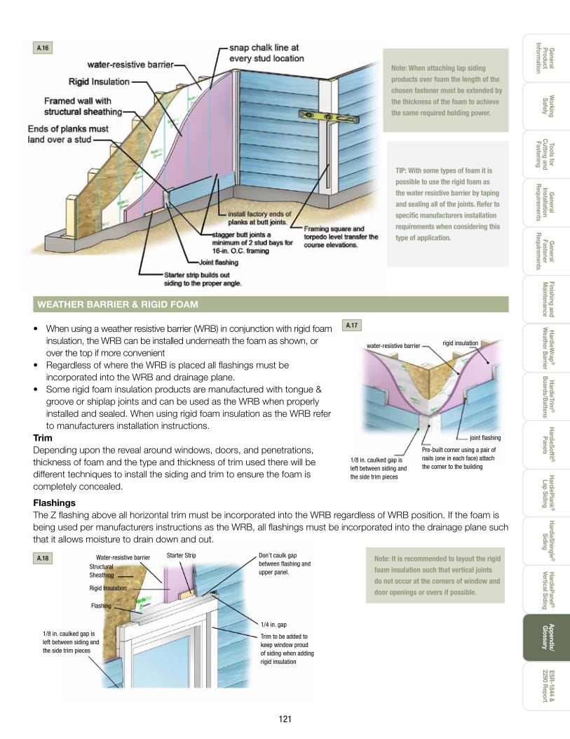
Starter strip builds out siding to the proper angle
Nailing Flange
Joint flashing
Install factory ends of planks at butt joints
Refer to ICF Manufacturer for compliant fastening
Note: Fastener bearing area is equal to the
head area less the shank area.

Gen
eral
Pr
oduc
t In
form
atio
n
Wor
king
Sa
fely
Tool
s fo
r C
uttin
g an
d Fa
sten
ing
Gen
eral
In
stal
latio
nR
equi
rem
ents
Gen
eral
Fa
sten
er
Req
uire
men
ts
Fini
shin
g an
dM
aint
enan
ceH
ardi
eTrim
®
Boa
rds/
Bat
tens
Har
dieW
rap®
Wea
ther
Bar
rier
Har
dieS
offit
®
Pan
els
Har
dieP
lank
®
Lap
Sid
ing
Har
dieS
hing
le®
Sid
ing
Har
dieP
anel
®
Ver
tical
Sid
ing
ESR
-184
4 &
2290
Rep
ort
Appe
ndix
/G
loss
ary
120
The application of HardiePlank® Lap Siding and HardieTrim® boards to masonry construction complying with local building codes using Concrete Masonry Units (CMU) complying to ASTM C 90 can be achieved by using one of the following two methods of attachment. All other product specific installation requirements which are not outlined below must be followed.
Method 1: Attachment Over FurringAttach over furring with adequate thickness to allow attachment with approved fastening methods according to local building codes and code compliance documentation. Furring must be attached to ensure it can transfer the wind loads and other necessary forces back to the structure. The mechanical connection of the furring to the structure is the responsibility of the Licensed Design Professional. James Hardie Building Products has no comment on the load carrying capacity of the furring to framing connections.
Method 2: Attachment Directly to CMUAttach directly to masonry with approved fastening method according to local building codes and code compliance documentation. Refer to and follow local building codes for water resistive barrier requirements.
Attachment of HardieTrim® boardsHardieTrim boards can be fastened using hardened finish nails designed for masonry construction. For more information refer to the HardieTrim section of this guide.
Fastening to CMUFor information on fastening James Hardie products to CMU refer to ESR 1844 & 2290
ATTACHING HARDIEPLANK® LAP SIDING AND HARDIETRIM® PRODUCTS TO CONCRETE MASONRY UNITS (CMU)
Spaced maximum 24” O.C. CMU
wall
Furring strips to accommodate siding fastener length
6” clearance to grade
Starter strip(same as
plank)HardiePlank®
lap siding Trim
CMU wall
6” clearance to grade
Starter strip(same as
plank) HardiePlank® lap siding Trim
Blind nailingsiding fastener
Furring strip to accommodate siding
fastener length
Masonry fastener
Blind nailingsiding fastener
Masonry siding nail
HardiePlank® lap siding
A.10
A.12
A.11
A.13
Appendix A (cont.)
General
Product Inform
ation
Tools for C
utting and Fastening
General
InstallationR
equirements
General
Fastener R
equirements
Finishing andM
aintenanceH
ardieTrim®
Boards/B
attensH
ardieWrap
®
Weather B
arrierH
ardieSoffit ®
PanelsH
ardiePlank®
Lap SidingH
ardieShingle®
SidingH
ardiePanel ®
Vertical SidingESR
-1844 &2290 R
eportAppendix/G
lossaryW
orking Safely
121
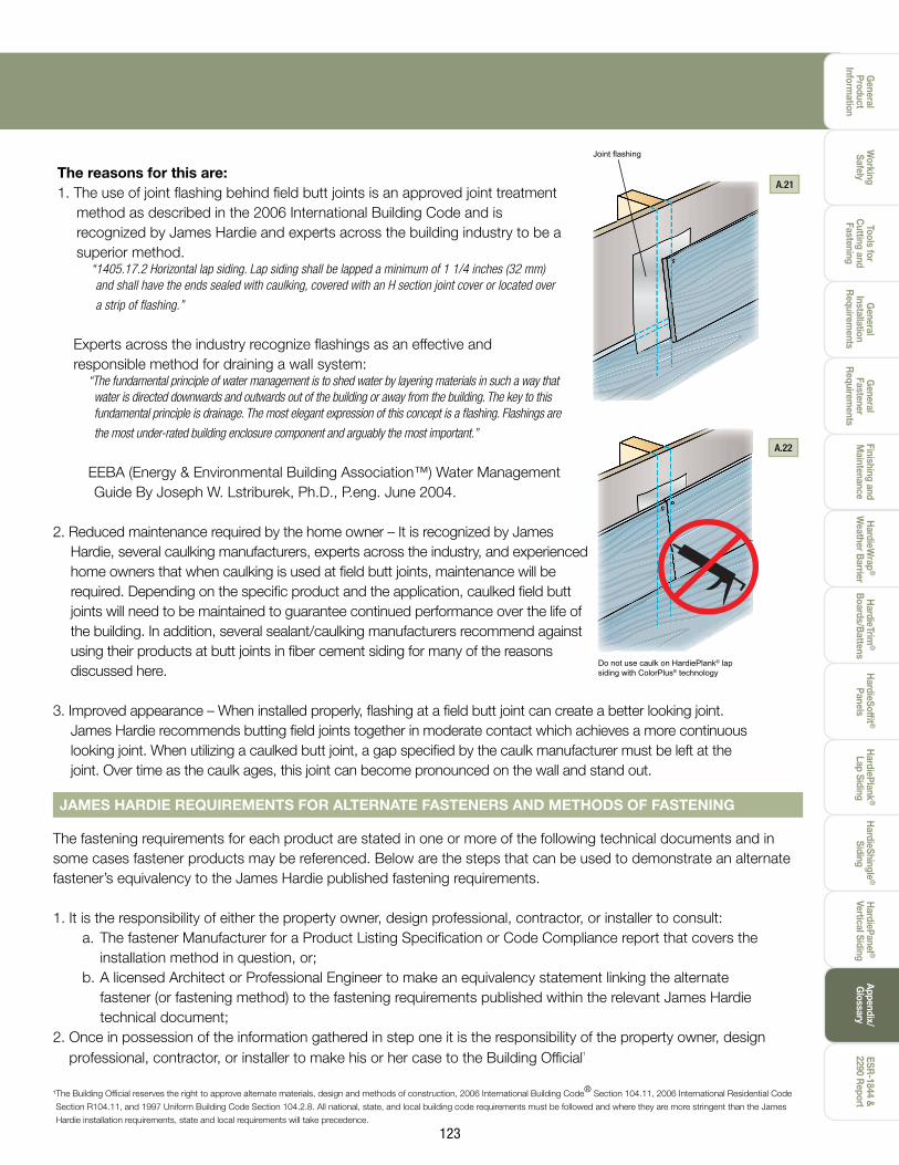
water-resistive barrier
joint flashing
Pre-built corner using a pair of nails (one in each face) attach the corner to the building
1/8 in. caulked gap is left between siding and the side trim pieces
rigid insulation
TIP: With some types of foam it is
possible to use the rigid foam as
the water resistive barrier by taping
and sealing all of the joints. Refer to
specific manufacturers installation
requirements when considering this
type of application.
Note: When attaching lap siding
products over foam the length of the
chosen fastener must be extended by
the thickness of the foam to achieve
the same required holding power.
A.16
FlashingsThe Z flashing above all horizontal trim must be incorporated into the WRB regardless of WRB position. If the foam is being used per manufacturers instructions as the WRB, all flashings must be incorporated into the drainage plane such that it allows moisture to drain down and out.
Note: It is recommended to layout the rigid
foam insulation such that vertical joints
do not occur at the corners of window and
door openings or overs if possible.
• When using a weather resistive barrier (WRB) in conjunction with rigid foam insulation, the WRB can be installed underneath the foam as shown, or over the top if more convenient
• Regardless of where the WRB is placed all flashings must be incorporated into the WRB and drainage plane.
• Some rigid foam insulation products are manufactured with tongue & groove or shiplap joints and can be used as the WRB when properly installed and sealed. When using rigid foam insulation as the WRB refer to manufacturers installation instructions.
TrimDepending upon the reveal around windows, doors, and penetrations, thickness of foam and the type and thickness of trim used there will be different techniques to install the siding and trim to ensure the foam is completely concealed.
WEATHER BARRIER & RIGID FOAM
A.17
A.18 Don’t caulk gap between flashing and upper panel.
Trim to be added to keep window proud of siding when adding rigid insulation
1/8 in. caulked gap is left between siding and the side trim pieces
Flashing
Rigid Insulation
Structural Sheathing
Water-resistive barrier Starter Strip
1/4 in. gap

Gen
eral
Pr
oduc
t In
form
atio
n
Wor
king
Sa
fely
Tool
s fo
r C
uttin
g an
d Fa
sten
ing
Gen
eral
In
stal
latio
nR
equi
rem
ents
Gen
eral
Fa
sten
er
Req
uire
men
ts
Fini
shin
g an
dM
aint
enan
ceH
ardi
eTrim
®
Boa
rds/
Bat
tens
Har
dieW
rap®
Wea
ther
Bar
rier
Har
dieS
offit
®
Pan
els
Har
dieP
lank
®
Lap
Sid
ing
Har
dieS
hing
le®
Sid
ing
Har
dieP
anel
®
Ver
tical
Sid
ing
ESR
-184
4 &
2290
Rep
ort
Appe
ndix
/G
loss
ary
122
INSTALLING HARDIEPLANK® LAP SIDING AROUND WINDOWS WITH AN INTEGRATED J-CHANNEL
When installing fiber cement around a window with a “J” channel there are a few guidelines which should be followed to control water flow:
1. All windows must be installed per manufacturers installation instructions and must incorporate all necessary flashings.
2. At the bottom sides of the window, a flashing must be installed that will redirect any water that runs down the inside of the “J” channel out and away so that it does not run down the wall assembly and behind the plank below the window.
a. This can be done by inserting a flashing that runs the entire length of the window (option 1. or by cutting the weather resistive barrier towards the bottom of the window and inserting a smaller flashing and taping with seam tape to reseal the weather resistive barrier (option 2).
b. This flashing would then be lapped over the last plank at the bottom of the window, similar to a joint flashing, to direct water down and out to the front of the cladding.
3. A “z” flashing must be installed and integrated into the weather resistive barrier at the top of the window. The “z” flashing will allow water to be drained away from the window and wall, opposed to being captured in the “J” at the top of the window. (Refer to James Hardie Installation Instructions for further “z” flashing details).
4. Seal all field cut non factory ends with an exterior grade paint, primer, or sealer.a. Insert ends of plank into the “J” channel of the window.b. Do not try to squeeze caulk into the “J” channel. c. Plank integrated into “J” channel must be primed, painted or caulked.
Typical “J” Channel Window
®®
®®
Wrap ® Tape Hardie
Weather Resistive Barrier Z Flashing (Refer to James Hardie Installation Instructions)
Flashing
J Channel of Window
Seal field cut ends Do not caulk
A.20
JOINT FLASHING WITH HARDIEPLANK® LAP SIDING
Wrap ® Tape Hardie ®®
®®
®
Weather Resistive Barrier
Option 1 Option 2
Weather Resistive Barrier
One piece of Flashing
Weather Resistive Barrier
Seam Tape
Pieces of Flashing
®
A.19
One or more of the following joint treatment options are required by code (as referenced 2009 IRC R703.10.2)A. Joint Flashing (James Hardie recommended)B. Caulking* (Caulking is not recommended for ColorPlus for aesthetic reasons as the Caulking and ColorPlus will
weather differently. For the same reason, do not caulk nail heads on ColorPlus products.)C. “H” jointer cover Flashing behind butt joints provides an extra level of protection against the entry of water at
the joint.
James Hardie recommends 6 in. wide flashing that overlaps the course below by 1 in. Some local building codes may require different size flashing. Joint-flashing material must be durable, waterproof materials that do not react with cement products. Examples of suitable material include finished coil stock and code compliant water-resistive barriers. Other products may also be suitable.
Typical "J" Channel Window
Appendix A (cont.)
General
Product Inform
ation
Tools for C
utting and Fastening
General
InstallationR
equirements
General
Fastener R
equirements
Finishing andM
aintenanceH
ardieTrim®
Boards/B
attensH
ardieWrap
®
Weather B
arrierH
ardieSoffit ®
PanelsH
ardiePlank®
Lap SidingH
ardieShingle®
SidingH
ardiePanel ®
Vertical SidingESR
-1844 &2290 R
eportAppendix/G
lossaryW
orking Safely
123
The reasons for this are:1. The use of joint flashing behind field butt joints is an approved joint treatment
method as described in the 2006 International Building Code and is recognized by James Hardie and experts across the building industry to be a superior method.
“1405.17.2 Horizontal lap siding. Lap siding shall be lapped a minimum of 1 1/4 inches (32 mm) and shall have the ends sealed with caulking, covered with an H section joint cover or located over
a strip of flashing.”
Experts across the industry recognize flashings as an effective and responsible method for draining a wall system:
“The fundamental principle of water management is to shed water by layering materials in such a way that water is directed downwards and outwards out of the building or away from the building. The key to this fundamental principle is drainage. The most elegant expression of this concept is a flashing. Flashings are
the most under-rated building enclosure component and arguably the most important.”
EEBA (Energy & Environmental Building Association™) Water Management Guide By Joseph W. Lstriburek, Ph.D., P.eng. June 2004.
2. Reduced maintenance required by the home owner – It is recognized by James Hardie, several caulking manufacturers, experts across the industry, and experienced home owners that when caulking is used at field butt joints, maintenance will be required. Depending on the specific product and the application, caulked field butt joints will need to be maintained to guarantee continued performance over the life of the building. In addition, several sealant/caulking manufacturers recommend against using their products at butt joints in fiber cement siding for many of the reasons discussed here.
3. Improved appearance – When installed properly, flashing at a field butt joint can create a better looking joint. James Hardie recommends butting field joints together in moderate contact which achieves a more continuous looking joint. When utilizing a caulked butt joint, a gap specified by the caulk manufacturer must be left at the joint. Over time as the caulk ages, this joint can become pronounced on the wall and stand out.
Joint flashing
Do not use caulk on HardiePlank® lap siding with ColorPlus® technology
A.21
A.22
The fastening requirements for each product are stated in one or more of the following technical documents and in some cases fastener products may be referenced. Below are the steps that can be used to demonstrate an alternate fastener’s equivalency to the James Hardie published fastening requirements.
1. It is the responsibility of either the property owner, design professional, contractor, or installer to consult: a. The fastener Manufacturer for a Product Listing Specification or Code Compliance report that covers the installation method in question, or; b. A licensed Architect or Professional Engineer to make an equivalency statement linking the alternate fastener (or fastening method) to the fastening requirements published within the relevant James Hardie technical document;2. Once in possession of the information gathered in step one it is the responsibility of the property owner, design professional, contractor, or installer to make his or her case to the Building Official¹
¹ The Building Official reserves the right to approve alternate materials, design and methods of construction, 2006 International Building Code® Section 104.11, 2006 International Residential Code
Section R104.11, and 1997 Uniform Building Code Section 104.2.8. All national, state, and local building code requirements must be followed and where they are more stringent than the James
Hardie installation requirements, state and local requirements will take precedence.
JAMES HARDIE REQUIREMENTS FOR ALTERNATE FASTENERS AND METHODS OF FASTENING

Gen
eral
Pr
oduc
t In
form
atio
n
Wor
king
Sa
fely
Tool
s fo
r C
uttin
g an
d Fa
sten
ing
Gen
eral
In
stal
latio
nR
equi
rem
ents
Gen
eral
Fa
sten
er
Req
uire
men
ts
Fini
shin
g an
dM
aint
enan
ceH
ardi
eTrim
®
Boa
rds/
Bat
tens
Har
dieW
rap®
Wea
ther
Bar
rier
Har
dieS
offit
®
Pan
els
Har
dieP
lank
®
Lap
Sid
ing
Har
dieS
hing
le®
Sid
ing
Har
dieP
anel
®
Ver
tical
Sid
ing
ESR
-184
4 &
2290
Rep
ort
Appe
ndix
/G
loss
ary
124
EstimatingSiding
All houses can be broken down to triangles, rectangles, and squares. Using these simple shapes it is very easy to estimate the amount of siding required.
1. Break down the portions of the house to be sided into the simple shapes (squares, rectangles, triangles) Figures 12.1 - 12.4.
2. Determine the height and width of each shape.
3. Multiply height x width to determine square footage. For triangles divide the total by 2.
4. Add all of the square footage numbers together.
5. Subtract large items such as garage doors, large doors, large windows, and banks of windows from total. Do not remove small windows, doors, vents, or other small areas not being sided.
6. Total all numbers. This gives you the total covered area.
7. Use the coverage charts located in this section to determine the number needed.
8. Add a minimum of 5% for waste. If there are multiple (3 or more) gables, chases, bump outs, or dormers add 10%.** Material for starter strip is included in the calculation for waste.
Trim
Number of HardieTrim® Boards: Trim is applied to corners and around doors and windows. Trim is also used for fascia board, rake board, band board, frieze board and other details.
1. Determine which areas are to be trimmed.
2. Measure all openings to be trimmed including doors, windows, vent openings, corners (inside and outside), and other areas.
3. Measure for fascia, rakes, and frieze boards.
4. Add the lengths for corners, fascia, rakes, and frieze and add 5% for waste.
5. Add the lengths for window and door trim and add 10% for waste.
6. Add the total from lines 4 and 5 to determine the amount of trim needed.
Disclaimer: The estimation methods in this section are meant as a guide. James Hardie does not assume responsibility for over or under ordering of product.
Wall Area
Height
WidthHeight _____feet x width _____ feet =_____ square feet
Gable Area
Height
Width
1/2 height x width = _____ area of gable (square feet)
Gambrel Roof House
A
Width
1/2 (A+B) x C + 1/2 B x D = _____ total area of gable (square feet)
Dormer Area
Height
Width
1/2 height x width = _____ area of dormer (square feet)
D
BC
B.1
B.2
B.3
B.4
Rake Board
Band Board
Corner Trim
Door Trim
Fascia
Frieze
Window Trim
B.5
Appendix B

General
Product Inform
ation
Tools for C
utting and Fastening
General
InstallationR
equirements
General
Fastener R
equirements
Finishing andM
aintenanceH
ardieTrim®
Boards/B
attensH
ardieWrap
®
Weather B
arrierH
ardieSoffit ®
PanelsH
ardiePlank®
Lap SidingH
ardieShingle®
SidingH
ardiePanel ®
Vertical SidingESR
-1844 &2290 R
eportAppendix/G
lossaryW
orking Safely
125
HardiePlank® Lap Siding Coverage Chart* (number of planks)
Coverage Area Plank Width (in)
(square feet)
W. (in) 5.25 6.25 7.25 8.25 9.25 12 Exp. (in) 4 5 6 7 8 10.75
100 25 20 17 14 13 9 200 50 40 33 29 25 19 300 75 60 50 43 38 28 400 100 80 67 57 50 37 500 125 100 83 71 63 47 600 150 120 100 86 75 56 700 175 140 117 100 88 65 800 200 160 133 114 100 74 900 225 180 150 129 113 84 1000 250 200 167 143 125 93 1100 275 220 183 157 138 102 1200 300 240 200 171 150 112 1300 325 260 217 186 163 121 1400 350 280 233 200 175 130 1500 375 300 250 214 188 140 1600 400 320 267 229 200 149 1700 425 340 283 243 213 158 1800 450 360 300 257 225 167 1900 475 380 317 271 238 177 2000 500 400 333 286 250 186 2100 525 420 350 300 263 195 2200 550 440 367 314 275 205 2300 575 460 383 329 288 214 2400 600 480 400 343 300 223 2500 625 500 417 357 313 233 2600 650 520 433 371 325 242 2700 675 540 450 386 338 251 2800 700 560 467 400 350 260 2900 725 580 483 414 363 270 3000 750 600 500 429 375 279
The estimation methods in this section are meant as a guide. James Hardie does not assume responsibility for over or under ordering of product.
*Coverage chart does not include waste. ** Number of nails given are for building framed 16 in o.c.
Nail Coverage Chart** (number of nails)
Coverage Area Plank Width (in)
(square feet) Width (in) 5.25 6.25 7.25 8.25 9.25 12
Exposure (in) 4 5 6 7 8 10.75
100 250 200 166 143 125 93 500 1250 1000 830 715 625 465 1000 2500 2000 1660 1430 1250 930
HardiePanel® Vertical Siding Coverage Chart* (number of panels)
Coverage Area Panel Size (ft)
(square feet)
4x8 4x9 4x10 (32SF) (36SF) (40SF)
100 4 3 3 200 7 6 5 300 10 9 8 400 13 12 10 500 16 14 13 600 19 15 15 700 22 20 18 800 25 23 20 900 29 25 23 1000 32 28 25 1100 35 31 28 1200 38 34 30 1300 41 37 33 1400 44 39 35 1500 47 42 38 1600 50 45 40 1700 54 48 43 1800 57 50 45 1900 60 53 48 2000 63 56 50 2100 66 59 53 2200 69 62 55 2300 72 64 58 2400 75 67 60 2500 79 70 63 2600 82 73 65 2700 85 75 68 2800 88 78 70 2900 91 81 73 3000 94 84 75
Gen
eral
Pr
oduc
t In
form
atio
n
Wor
king
Sa
fely
Tool
s fo
r C
uttin
g an
d Fa
sten
ing
Gen
eral
In
stal
latio
nR
equi
rem
ents
Gen
eral
Fa
sten
er
Req
uire
men
ts
Fini
shin
g an
dM
aint
enan
ceH
ardi
eTrim
®
Boa
rds/
Bat
tens
Har
dieW
rap®
Wea
ther
Bar
rier
Har
dieS
offit
®
Pan
els
Har
dieP
lank
®
Lap
Sid
ing
Har
dieS
hing
le®
Sid
ing
Har
dieP
anel
®
Ver
tical
Sid
ing
ESR
-184
4 &
2290
Rep
ort
Appe
ndix
/G
loss
ary
126
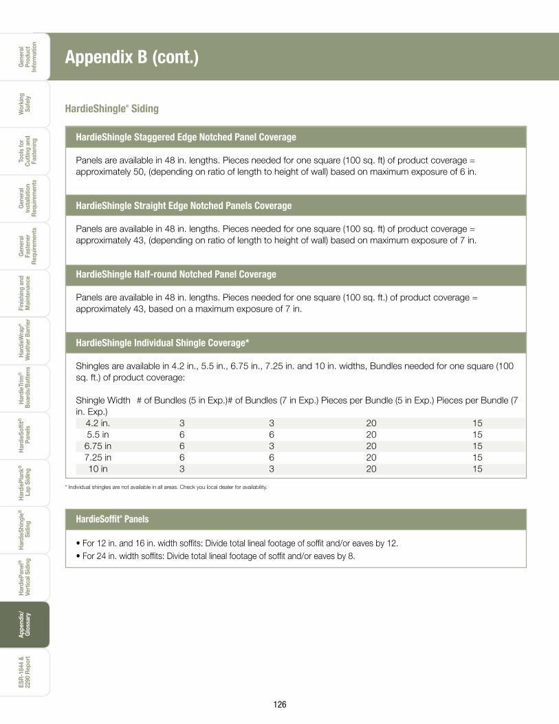
HardieShingle® Siding
HardieShingle Staggered Edge Notched Panel Coverage
Panels are available in 48 in. lengths. Pieces needed for one square (100 sq. ft) of product coverage = approximately 50, (depending on ratio of length to height of wall) based on maximum exposure of 6 in.
HardieShingle Straight Edge Notched Panels Coverage
Panels are available in 48 in. lengths. Pieces needed for one square (100 sq. ft) of product coverage = approximately 43, (depending on ratio of length to height of wall) based on maximum exposure of 7 in.
HardieShingle Half-round Notched Panel Coverage
Panels are available in 48 in. lengths. Pieces needed for one square (100 sq. ft.) of product coverage = approximately 43, based on a maximum exposure of 7 in.
HardieShingle Individual Shingle Coverage*
Shingles are available in 4.2 in., 5.5 in., 6.75 in., 7.25 in. and 10 in. widths, Bundles needed for one square (100 sq. ft.) of product coverage:
Shingle Width # of Bundles (5 in Exp.) # of Bundles (7 in Exp.) Pieces per Bundle (5 in Exp.) Pieces per Bundle (7 in. Exp.) 4.2 in. 3 3 20 15 5.5 in 6 6 20 15 6.75 in 6 3 20 15 7.25 in 6 6 20 15 10 in 3 3 20 15
* Individual shingles are not available in all areas. Check you local dealer for availability.
HardieSoffit® Panels
• For 12 in. and 16 in. width soffits: Divide total lineal footage of soffit and/or eaves by 12.• For 24 in. width soffits: Divide total lineal footage of soffit and/or eaves by 8.
Appendix B (cont.)

General
Product Inform
ation
Tools for C
utting and Fastening
General
InstallationR
equirements
General
Fastener R
equirements
Finishing andM
aintenanceH
ardieTrim®
Boards/B
attensH
ardieWrap
®
Weather B
arrierH
ardieSoffit ®
PanelsH
ardiePlank®
Lap SidingH
ardieShingle®
SidingH
ardiePanel ®
Vertical SidingESR
-1844 &2290 R
eportAppendix/G
lossaryW
orking Safely
127
Glossary of Building TermsBack Roll - To roll over a freshly spray painted surface with a roller.
Back Sealing/Priming - Back sealing and back priming are used interchangeably in the field and refer to the act of applying a sealer or primer to the back of a cladding material to minimize the potential for water absorption through the backside of the product.
Band Board - A decorative piece of trim placed between two floors along the rim joist.
Bevel Cut - See weather cut
Blind Nailing - The action of placing a fastener through the top edge of lap siding that will be covered by the next course of siding.
Bump Out - A built out protrusion from a building.
Butt Joint - To place materials end-to-end or end-to-edge without overlapping. Also known as a field joint.
Caulk - A compound used to fill cracks, gaps, seams and joints.
Chase - A framed enclosed space around a flue pipe or a channel in a wall, or through a ceiling for something to lie in or pass through.
Course - A row of planks, one plank wide running the length of the house.
Dormer - A gabled extension built out from a sloping roof to accommodate a vertical window.
Drip Cap - A molding or metal flashing placed on the ex-terior topside of a door or window frame to cause water to drip beyond the outside of the frame.
Drip Edge - A metal or vinyl flashing placed on the top edge of the roof sheathing which directs water away from the structure to prevent seepage under or behind the exterior trim or fascia.
Eave - The lower part of the roof that projects over the exterior wall assembly.
Electro-Galvanized - Covered with zinc using a plating process.
Face - The side of the siding, trim, or soffit showing once the product has been installed.
Face Nailing - The action of placing a fastener through the overlap of a plank. The fastener will be visible.
Fascia Board - A trim board attached to the ends of the rafters.
Finished Grade - The level at which the ground surface meets the foundation of a building.
Flashing - A thin flat metal positioned under/behind roof-ing, windows, doors, corner posts, etc. to keep draining water from penetrating the house.
Frieze Board - A horizontal member connecting the top of the siding with the soffit
Furring/Furring Strip - Furring strips are long, thin strips of wood, metal or Fiber Cement used to make backing surfaces to support the finished surfaces.
Gable - The end of a wall that is created when a roof line is pitched and slopes in two directions.
Galvanized - Covered with zinc. Either hot-dipped or electro-plated.
Grade - The height of the ground on which something stands.
Horizontal - Parallel to the horizon; on a level.
Joint Flashing - An additional weather resistive barrier placed behind a butt joint.
Lap - To over lap a course of siding with another course of siding.
Level - A position of measurement truly and exactly hori-zontal, 90° from a plumb surface.
Light Block - Decorative trim item placed under light fixtures and other exterior fixtures.
Miter - To make a diagonal cut, beveled to a specific angle 45° and 22 1/2 ° are common.
Appendix C
Gen
eral
Pr
oduc
t In
form
atio
n
Wor
king
Sa
fely
Tool
s fo
r C
uttin
g an
d Fa
sten
ing
Gen
eral
In
stal
latio
nR
equi
rem
ents
Gen
eral
Fa
sten
er
Req
uire
men
ts
Fini
shin
g an
dM
aint
enan
ceH
ardi
eTrim
®
Boa
rds/
Bat
tens
Har
dieW
rap®
Wea
ther
Bar
rier
Har
dieS
offit
®
Pan
els
Har
dieP
lank
®
Lap
Sid
ing
Har
dieS
hing
le®
Sid
ing
Har
dieP
anel
®
Ver
tical
Sid
ing
ESR
-184
4 &
2290
Rep
ort
Appe
ndix
/G
loss
ary
128
Mud Sill - A building member resting and normally at-tached to the foundation of a building running around the perimeter of the building. Also known as sill plate.
OSB - Oriented Strand Board. A common type of struc-tural panel sheathing.
PEL - Personal Permisible Exposure Limit. The maximum daily exposure level to respirable silica. OSHA’s Personal Exposure Limit is 0.1 mg/m3.
Plumb - A position of measurement truly and exactly vertical, 90° from a level surface.
Plunge Cut - The act of driving a saw into the body of a material.
Rafter Tail - The end of a rafter extending past the wall assembly.
Rain Screen Wall - Consists of an exterior cladding, a cavity behind the cladding typically created through the use of furring strips for the purpose of drainage and venting to the outside; an innerwall plane incorporating a weather resistive barrier.
Rake Board - Decorative trim placed at an angle.
Rigid Sheathing - Plywood or OSB.
Rim Joist - The board that the rest of the joists are nailed to. It runs the entire perimeter of the house.
Rip Cut - Cut along the grain, usually lengthwise on a board.
Scroll Work - Decorative trim work.
Sheathing - Sheets of plywood, gypsum board, or other material nailed to the outside face of studs as a base for exterior siding.
Shim - A building material, usually wood, used to even a surface.
Silica - Mineral that is composed of silicon dioxide, SiO2.
Speed Square - Triangle shaped measuring device used in a variety of framing and siding applications.
Stage - To deliver, stack, or store material in a specific location.
Starter Strip - An accessory used under the first course of siding to provide a consistent plank angle.
Sub-Fascia - Framing member attached to the rafter tails used to support the fascia or used to pad out the fascia.
T-Shed – A shed with a single vertical wall and a roof that hangs off that wall on either side. The cross section of the shed is shaped like a ‘T’.
Vertical - Being or situated at right angles to the horizon; upright.
Weather Cut- 15° to 45° cut used to join two boards.
Weather-Resistive Barrier- A building paper that pro-tects building materials from exterior water penetration.
Z-Flashing- A piece of flashing bent into the shape of a “z”. Used over window trim, band boards, panel intersec-tions, and other vertical surfaces.
Appendix C (cont.)

General
Product Inform
ation
Tools for C
utting and Fastening
General
InstallationR
equirements
General
Fastener R
equirements
Finishing andM
aintenanceH
ardieTrim®
Boards/B
attensH
ardieWrap
®
Weather B
arrierH
ardieSoffit ®
PanelsH
ardiePlank®
Lap SidingH
ardieShingle®
SidingH
ardiePanel ®
Vertical SidingESR
-1844 &2290 R
eportAppendix/G
lossaryW
orking Safely
129
Note: All building work must be in accordance with the applicable local building codes. The following is a list of the key code clauses. It is provided as a reference tool and not intended to be a substitute for proper design of ap-proved construction. ASTM E1825 also provides guidance on the evaluation of materials, products an systems used in exterior wall construction.
Appendix D
Site and Foundations2003,2006,2009,2012, 2015 International Building CodeChapter 18 Foundations and Retaining Walls1803.3 (03,06) Site grading; 1804.3 (09,12) Site grading; 1804.4 (15) Site grading
2003 2006, 2009, 2012, 2015 International ResidentialCode for One- and Two- Family DwellingsChapter 4 FoundationsR401.3 Drainage
Ground Clearances 2003, 2006, 2009, 2012, 2015 International Building CodeChapter 18 Foundations and Retaining Walls1803.3 (03,06) Site grading; 1804.3 (09,12) Site grading; 1804.4 (15) Site gradingChapter 23 Wood2304.11.2.2 (03, 06, 09, 12)Wood supported by exterior foundation walls.
2304.12.1.2 (15) Wood supported by exterior foundation walls2003, 2006, 2009, 2012, 2015 International Residential Codefor One- and Two- Family DwellingsChapter 3 Building PlanningChapter 4 FoundationsR404.1.6 Height above finished grade
Moisture Management2003, 2006, 2009, 2012, 2015 International Building CodeChapter 14 Exterior Walls1404.1 General1404.2 Weather-resistive barrier1405.1 General1405.2 Weather Protection1405.3 Flashing (03,06)1405.4 Flashing (09,12, 15)1405.17 (03,06) Joints1405.16 (09,12, 15) Joints
2003, 2006, 2009, 2012, 2015 International Residential Codefor One- and Two- Family DwellingsChapter 7 Wall CoveringR703.2 Weather-resistant barrierR703.8 FlashingR703.10 Joints
Wall Construction2003, 2006, 2009, 2012, 2015 International Building CodeChapter 22 SteelChapter 23 Wood
2003, 2006, 2009, 2012, 2015 International Residential Code for One- and Two- Family DwellingsChapter 6 Wall ConstructionR602.10 Wall bracing
Fastening2003, 2006, 2009, 2012, 2015 International Building CodeChapter 14 Exterior Walls1405.15 (03,06) Fiber cement siding1405.16 (09,12, 15) Fiber cement siding1406.2.2 (03, 06) Architectural trim1406.2.2.2( 09) Trim1406.2 (12, 15) Combustible exterior wall coverage
2003, 2006, 2009, 2012, 2015 International Residential Code for One- and Two- Family DwellingsChapter 7 Wall CoveringR703.4 (03, 06, 09, 12) AttachmentsR703.3 (15) Nominal thickness and attachments
Code References

Gen
eral
Pr
oduc
t In
form
atio
n
Wor
king
Sa
fely
Tool
s fo
r C
uttin
g an
d Fa
sten
ing
Gen
eral
In
stal
latio
nR
equi
rem
ents
Gen
eral
Fa
sten
er
Req
uire
men
ts
Fini
shin
g an
dM
aint
enan
ceH
ardi
eTrim
®
Boa
rds/
Bat
tens
Har
dieW
rap®
Wea
ther
Bar
rier
Har
dieS
offit
®
Pan
els
Har
dieP
lank
®
Lap
Sid
ing
Har
dieS
hing
le®
Sid
ing
Har
dieP
anel
®
Ver
tical
Sid
ing
ESR
-184
4 &
2290
Rep
ort
Appe
ndix
/G
loss
ary
130
ESR Reports Online
HARDIEPLANK® LAP SIDING & HARDIESHINGLE® SIDING
ESR 2290
HARDIEPANEL® VERTICAL SIDING
ESR 1844
HARDIEBACKER® CEMENT BOARDS
ESR 2280
HARDIEWRAP® WEATHER BARRIER
ESR 2658
The links below are the most current ESR reports and wind load tables as of March 2016.
To find the most current ESR reports please visit www.icc-es.org.