adept motionblox-10 servo kit - your intelligent … motionblox-10 servo kit installation guide,...
TRANSCRIPT

Adept MotionBlox-10Servo Kit
Installation Guide


Adept MotionBlox-10Servo Kit
Installation Guide
P/N: 05851-000, Rev. BApril 2007
3011 Triad Drive • Livermore, CA 94551 • USA • Phone 925.245.3400 • Fax 925.960.0452
Otto-Hahn-Strasse 23 • 44227 Dortmund • Germany • Phone 49.231.75.89.40 • Fax 49.231.75.89.450
41, rue du Saule Trapu • 91882 • Massy • France • Phone 33.1.69.19.16.16 • Fax 33.1.69.32.04.62

The information contained herein is the property of Adept Technology, Inc., and shall not be reproduced in whole or in part without prior written approval of Adept Technology, Inc. The information herein is sub-ject to change without notice and should not be construed as a commitment by Adept Technology, Inc. This manual is periodically reviewed and revised.
Adept Technology, Inc., assumes no responsibility for any errors or omissions in this document. Critical evaluation of this manual by the user is welcomed. Your comments assist us in preparation of future doc-umentation. Please e-mail your comments to: [email protected].
Copyright ©2002, 2003, 2005, 2006, 2007 by Adept Technology, Inc. All rights reserved.
The Adept logo, AdeptVision, AIM, HexSight, and HexaVisionare registered trademarks of Adept Technology, Inc.
ActiveV, Adept, Adept 1060, Adept 1060+, Adept 1850, Adept 1850 XP, Adept 540, Adept 560, Adept C40, Adept C60, Adept CC, Adept Cobra 550, Adept Cobra 550 CleanRoom, Adept Cobra 600, Adept Cobra 800, Adept Cobra i600, Adept Cobra i800, Adept Cobra s600, Adept Cobra s800, Adept DeskTop, Adept Digital Workcell, Adept FFE, Adept FlexFeeder 250, Adept IC, Adept Impulse Feeder, Adept LineVision, Adept
MC, Adept MV, Adept MV-10, Adept MV-19, Adept MV4, Adept MV-5, Adept MV-8, Adept NanoBonder EBS, Adept NanoBonder LWS, Adept NanoCell, Adept NanoStage L1P2, Adept NanoStage L3, Adept NanoStage L3P2, Adept OC, Adept SmartAmp, Adept SmartAxis, Adept SmartController CS, Adept
SmartController CX, Adept SmartModule, Adept SmartMotion, Adept SmartServo, Adept sDIO, Adept Servo Kit, Adept sMI6, Adept SMIF-EZ, AdeptAlign 650, AdeptAtlas, AdeptCartesian, AdeptForce,
AdeptFTP, AdeptGEM, AdeptModules, AdeptMotion, AdeptMotion Servo, AdeptMotion VME, AdeptNet, AdeptNFS, AdeptOne, AdeptOne-MV, AdeptOne-XL, AdeptRAPID, AdeptSix 300, AdeptSix
300CL, AdeptSix 600, AdeptTCP/IP, AdeptThree, AdeptThree-MV, AdeptThree-XL, AdeptTwo, AdeptVicron, AdeptVicron 300S, AdeptVicron 310D, AdeptVision AVI, AdeptVision AGS, AdeptVision
GV, AdeptVision I, AdeptVision II, AdeptVision VME, AdeptVision VXL, AdeptVision XGS, AdeptVision XGS II, AdeptWindows, AdeptWindows Controller, AdeptWindows DDE, AdeptWindows Offline Editor,
AdeptWindows PC, AIM Command Server, AIM Dispense, AIM PCB, AIM VisionWare, A-Series, AutoCal, AutoTune, AutoWidth, CCM, CCMII, CGM, FlexFeedWare, HyperDrive, Microenvironment,
MicroV+, MotionWare, ObjectFinder, ObjectFinder 2000, PackOne, PalletWare, SMIF-C, SMIF-EZX, SMIF-Z, SMIF-ZX, S-Series, UltraOne, V, V+, and VisionTeach are trademarks of Adept Technology, Inc.
Any trademarks from other companies used in this publication are the property of those respective companies.
Printed in the United States of America

Table of Contents
1 Introduction . . . . . . . . . . . . . . . . . . . . . . . . . . . . . . . . . . . . . . . . . . . . . . . . 7
1.1 Product Description. . . . . . . . . . . . . . . . . . . . . . . . . . . . . . . . . . . . . . . . . . . . . . . . . 7
Adept Servo Kit . . . . . . . . . . . . . . . . . . . . . . . . . . . . . . . . . . . . . . . . . . . . . . . . . 7Servo Kit Components . . . . . . . . . . . . . . . . . . . . . . . . . . . . . . . . . . . . . . . . . . . . 7
Adept MB-10 . . . . . . . . . . . . . . . . . . . . . . . . . . . . . . . . . . . . . . . . . . . . . 7Servo Motors . . . . . . . . . . . . . . . . . . . . . . . . . . . . . . . . . . . . . . . . . . . . . 7
1.2 Required System Components . . . . . . . . . . . . . . . . . . . . . . . . . . . . . . . . . . . . . . . 8
Power Distribution Unit . . . . . . . . . . . . . . . . . . . . . . . . . . . . . . . . . . . . . . . . . . . . 8Use with Other Adept Robots . . . . . . . . . . . . . . . . . . . . . . . . . . . . . . . 8
1.3 Optional System Components. . . . . . . . . . . . . . . . . . . . . . . . . . . . . . . . . . . . . . . . 8
IO Blox Device . . . . . . . . . . . . . . . . . . . . . . . . . . . . . . . . . . . . . . . . . . . . . . . . . . 8
1.4 Available Support Resources. . . . . . . . . . . . . . . . . . . . . . . . . . . . . . . . . . . . . . . . . 8
How Can I Get Help? . . . . . . . . . . . . . . . . . . . . . . . . . . . . . . . . . . . . . . . . . . . . 8Related Manuals . . . . . . . . . . . . . . . . . . . . . . . . . . . . . . . . . . . . . . . . . . . . . . . . .9Adept Document Library . . . . . . . . . . . . . . . . . . . . . . . . . . . . . . . . . . . . . . . . . 9
2 Servo Kit Installation . . . . . . . . . . . . . . . . . . . . . . . . . . . . . . . . . . . . . . . . 11
2.1 Mounting the MB-10 T-Bracket . . . . . . . . . . . . . . . . . . . . . . . . . . . . . . . . . . . . . . 11
2.2 MB-10 T-Bracket Dimension Drawings . . . . . . . . . . . . . . . . . . . . . . . . . . . . . . . . 12
2.3 Mounting the MB-10 . . . . . . . . . . . . . . . . . . . . . . . . . . . . . . . . . . . . . . . . . . . . . . . 14
2.4 Mounting the Motor. . . . . . . . . . . . . . . . . . . . . . . . . . . . . . . . . . . . . . . . . . . . . . . . 14
2.5 Connecting the Motor to the MB-10 . . . . . . . . . . . . . . . . . . . . . . . . . . . . . . . . . . 15
Motor Cable Leads . . . . . . . . . . . . . . . . . . . . . . . . . . . . . . . . . . . . . . . . . . . . . 15Attaching the Encoder and Battery Cables. . . . . . . . . . . . . . . . . . . . . . . . . 15Attaching the Brake Cable . . . . . . . . . . . . . . . . . . . . . . . . . . . . . . . . . . . . . . .16Attaching the Motor Cable . . . . . . . . . . . . . . . . . . . . . . . . . . . . . . . . . . . . . . 16
2.6 Connecting Power to the MB-10 . . . . . . . . . . . . . . . . . . . . . . . . . . . . . . . . . . . . . 16
Attaching the 24 VDC Power Cable . . . . . . . . . . . . . . . . . . . . . . . . . . . . . . . 16Attaching the AC Power Cable . . . . . . . . . . . . . . . . . . . . . . . . . . . . . . . . . . .17Attaching the IEEE 1394 Cable. . . . . . . . . . . . . . . . . . . . . . . . . . . . . . . . . . . . 17Attaching the Interface Cable to the IO Blox Device (optional) . . . . . . . 17Installing the MB-10 T-Bracket Cover . . . . . . . . . . . . . . . . . . . . . . . . . . . . . . .18
2.7 Power Distribution Unit . . . . . . . . . . . . . . . . . . . . . . . . . . . . . . . . . . . . . . . . . . . . . 18
2.8 Adept Servo Kit Cable Diagram . . . . . . . . . . . . . . . . . . . . . . . . . . . . . . . . . . . . . 20
Adept MotionBlox-10 Servo Kit Installation Guide, Rev. B 5

Table of Contents
3 System Requirements and Specifications . . . . . . . . . . . . . . . . . . . . . . . 21
3.1 System Requirements . . . . . . . . . . . . . . . . . . . . . . . . . . . . . . . . . . . . . . . . . . . . . . 21
Power Requirements for SmartController System . . . . . . . . . . . . . . . . . . . . . 21
3.2 System Specifications . . . . . . . . . . . . . . . . . . . . . . . . . . . . . . . . . . . . . . . . . . . . . . 22
Servo Motor Specifications . . . . . . . . . . . . . . . . . . . . . . . . . . . . . . . . . . . . . . . 22Determining Maximum Number of Devices per PDU3 . . . . . . . . . . . . . . . . . 23
Calculation Example . . . . . . . . . . . . . . . . . . . . . . . . . . . . . . . . . . . . . . 23Motor Dimensions . . . . . . . . . . . . . . . . . . . . . . . . . . . . . . . . . . . . . . . . . . . . . . . 24
100 W Motor Dimensions (without brake) . . . . . . . . . . . . . . . . . . . . . 24100 W Motor Dimensions (with brake) . . . . . . . . . . . . . . . . . . . . . . . . 25200 W Motor Dimensions (without brake) . . . . . . . . . . . . . . . . . . . . . 26200 W Motor Dimensions (with brake) . . . . . . . . . . . . . . . . . . . . . . . . 27400 W Motor Dimensions (without brake) . . . . . . . . . . . . . . . . . . . . . 28400 W Motor Dimensions (with brake) . . . . . . . . . . . . . . . . . . . . . . . . 29750 W Motor Dimensions (without brake) . . . . . . . . . . . . . . . . . . . . . 30750 W Motor Dimensions (with brake) . . . . . . . . . . . . . . . . . . . . . . . . 31
3.3 MB-10 Servo Kit Cable Kits . . . . . . . . . . . . . . . . . . . . . . . . . . . . . . . . . . . . . . . . . . 32
Amp-to-Amp Cable Kits . . . . . . . . . . . . . . . . . . . . . . . . . . . . . . . . . . . . . . . . . . 32Amp-to-Motor Cable Kits . . . . . . . . . . . . . . . . . . . . . . . . . . . . . . . . . . . . . . . . . 32
4 Adept Servo Kit Software . . . . . . . . . . . . . . . . . . . . . . . . . . . . . . . . . . . . . 35
4.1 Overview. . . . . . . . . . . . . . . . . . . . . . . . . . . . . . . . . . . . . . . . . . . . . . . . . . . . . . . . . 35
4.2 Using CONFIG_C to Append Device Modules . . . . . . . . . . . . . . . . . . . . . . . . . . 35
4.3 Using DC_SETUP to Configure the Axis . . . . . . . . . . . . . . . . . . . . . . . . . . . . . . . . . 39
Configuration for JTS Coordinated-Joint-Control Robot Module . . . . . . . . 39Configuration for LM Linear-Module Robot Module. . . . . . . . . . . . . . . . . . . 44
4.4 Testing the Axis. . . . . . . . . . . . . . . . . . . . . . . . . . . . . . . . . . . . . . . . . . . . . . . . . . . . 48
4.5 Modifying the Default Parameters to Optimize Performance . . . . . . . . . . . . . . 50
6 Adept MotionBlox-10 Servo Kit Installation Guide, Rev. B

Introduction 11.1 Product Description
Adept Servo Kit
Adept Servo Kits offer a convenient and economical way to add one or more incremental axes to an existing system. The kits are plug-compatible with Adept's SmartServo distributed-servo network. The SmartServo network utilizes the IEEE-1394 protocol to provide real-time communications with an individual axis.
Servo Kit Components
The Servo Kit consists of an Adept MotionBlox-10 (MB-10), a matched AC servo motor with absolute encoder, an amplifier mounting bracket, and related documentation. Complementary components, such as power and interface cables, remote I/O kit, and cable accessories, are available as options.
Adept MB-10
The Adept MB-10 is a distributed-servo amplifier that can be mounted close to the motor, thereby eliminating the need for panel space typically required for servo amplifiers. This also simplifies installation and reduces the cables required to interface with the mechanism. As an option, motor and encoder extension harnesses made from high-flex robotic cable can be ordered.
The MB-10 features an on-board RISC microprocessor that executes the advanced servo loop. Adept’s IEEE-1394-based SmartServo network recognizes the MB-10 as a network node. The MB-10 is compatible with single-phase nominal AC voltage input of 200-240 V, 50 or 60 Hz.
Servo Motors
The servo motors for the Servo Kit are compact, CE compliant, low noise, high speed, and high power. The motors feature an absolute encoder that eliminates the need for homing. Encoder resolution is 65,536 counts per revolution. Additionally, the motors are totally enclosed and self-cooled by natural convection when mounted in an appropriate ambient environment. The MB-10 includes an internal regenerative dump resistor designed to handle approximately 20 Watts under nominal conditions. (For systems configured for regenerative power applications (such as vertical axes), contact Adept Customer Service for more information (see Section 1.4 on page 8).)
The servo motors are available in four sizes: 100 W, 200 W, 400 W, and 750 W. The primary advantage of the larger motors is the additional torque created. (The MB-10 amplifier is not able to drive the 750 W motor to its maximum capability.) All the motors are available with or without brakes.
Adept MotionBlox-10 Servo Kit Installation Guide, Rev. B 7

Chapter 1 - Introduction
1.2 Required System Components
Power Distribution Unit
The Power Distribution Unit (PDU3) is a safety device that switches AC power to the MB-10 when High Power is enabled. The PDU3 also supplies DC power for the MB-10 circuits.
Use with Other Adept Robots
If you are using an Adept Servo Kit with another Adept robot (such as an Adept Cobra, Viper, or Quatro), you will need the following additional items:
• PDU3 Expansion Kit - P/N 90430-30001
• XSYS Y-Cable - P/N 00411-000
• Kit for Multi-Mixed Robot Systems - P/N 06600-000
NOTE: Make sure that you install the Terminator plug on the open XSLV connector on the last PDU3 in your system.
1.3 Optional System Components
IO Blox Device
Adept offers a remote Input/Output option with the Adept Servo Kit. The IO Blox offers eight inputs and eight outputs, all optically isolated. You can daisy-chain up to four IO Blox devices per robot or MB-10 amp. See the Adept IO Blox User’s Guide for information.
1.4 Available Support Resources
How Can I Get Help?
Refer to the How to Get Help Resource Guide (Adept P/N 00961-00700) for details on getting assistance with your Adept software and hardware.
Additionally, you can access the following information sources on Adept’s corporate website:
• For Contact information: http://www.adept.com/main/contact/index. html
• For Product Support information: http://www.adept.com/main/services/index.asp
• For general information about Adept Technology, Inc.: http://www.adept.com
8 Adept MotionBlox-10 Servo Kit Installation Guide, Rev. B

Available Support Resources
Related Manuals
This guide covers the installation of the Servo Kit. There are additional manuals that cover programming, system configuration, and adding optional components. The following manuals (available on the Adept Document Library on CD-ROM) provide additional information related to the Servo Kit.
Adept Document Library
In addition to Adept’s Document Library on CD-ROM, you can find product documentation on the Adept web site in the Document Library area. The Document Library search engine allows you to locate information on a specific topic. Additionally, the Document Menu provides a list of available product documentation.
To access Adept’s Document Library, type the following URL into your browser:
http://www.adept.com/Main/KE/DATA/adept_search.htm
or, select the Adept Document Library link from the Services area of the Adept web site.
Table 1-1. Related Manuals
Manual Title Description
Adept SmartController User’s Guide
Describes the installation and operation of the Adept SmartController, and the sDIO product.
Adept Python Linear Modules User’s Guide
Describes how to assemble and install Adept Python Linear Modules.
Adept SmartMotion Developer Guide
Describes the SPEC utility used to modify servo tuning and calibration parameters.
Adept IO Blox User’s Guide Describes the IO Blox product.
Adept MotionBlox-10 Servo Kit Installation Guide, Rev. B 9


Servo Kit Installation 22.1 Mounting the MB-10 T-Bracket
The MB-10 fits securely onto the mounting T-bracket provided with your Adept Servo Kit. Use the M4 x 10 flathead screws to securely attach the mounting bracket to the desired mounting surface. See Figure 2-1.
Figure 2-1. The MB-10 Mounting T-Bracket
MB-10 T-Bracket
M4 x 10 Flathead screw (1 of 4)
MountingSurface
Adept MotionBlox-10 Servo Kit Installation Guide, Rev. B 11

Chapter 2 - Servo Kit Installation
2.2 MB-10 T-Bracket Dimension Drawings
Figure 2-2. Top View of MB-10 T-Bracket
Figure 2-3. Side View of MB-10 T-Bracket
-B-
141.38
∅11.20 x 90°28.58
115.57
70.69
4X R 2.032X
2X
49.99
∅5.51 THRU
∅8.97 x 90° SLOT10.49
56.08
2X
3.81
∅4.50 THRU SLOT
142.24
71.63
71.2538.61
4X M4
71.12
18.92
TYPICAL FAR SIDE
83.82
38.61
58.42
5.46 MIN
-A-
10.67
152.91146.56
12 Adept MotionBlox-10 Servo Kit Installation Guide, Rev. B

MB-10 T-Bracket Dimension Drawings
Figure 2-4. Back View of MB-10 T-Bracket
40.13
142.24
55.5
2X
49.02
10.16 121.9
1.57
2X
2X R25
4X R12
70.61
10.16
2X
2X
71.63
61.98
50.50
2X
8.97 x 902X
2X
-A-
19.05
18.24
2X
4X
6.354.50 THRU
3.81
-A-
4.40 THRU
19.51
15.01
10.49
4.50 THRU
FOR DIAMETER 5.512
2X
4.50 THRU SLOT
2X
23.37
28.58
53.49
6X
R5.08
8.97 x 90
30.00
2X
SLOT
1.14
11.20 x 90
2X 39.50
2X
8.97 x 905.512 THRU
2X
2.54
8.97 x 9025.53
Adept MotionBlox-10 Servo Kit Installation Guide, Rev. B 13

Chapter 2 - Servo Kit Installation
2.3 Mounting the MB-10
To mount the MB-10 onto the T-bracket, use the four M3 x 40 screws. See Figure 2-5.
Figure 2-5. Installing MB-10 onto the T-Bracket
2.4 Mounting the Motor
The servo motors included with the Servo Kit are designed for easy mounting. Refer to the dimension drawings in Chapter 3 to determine positions for mounting motors to the appropriate flange or adapter plate.
M3 x 40 Socket-HeadCap Screw (1 of 4)
MB-10
T-Bracket Cover
M3 FlatheadScrew (1 of 4)
14 Adept MotionBlox-10 Servo Kit Installation Guide, Rev. B

Connecting the Motor to the MB-10
2.5 Connecting the Motor to the MB-10
The following procedure details the sequence of steps that must be completed to connect the servo motor to the MB-10. Make sure that the system power is turned off before attaching any cables.
Motor Cable Leads
Motors have cable leads with the following plugs: an encoder plug, a motor plug, and a brake plug for those motors with brakes. See the “Adept MB-10 Amps” chapter in the Adept Python Linear Modules User’s Guide for plug specifications.
Attaching the Encoder and Battery Cables
Attach the encoder cable from the servo motor to the encoder connector on the MB-10 (see Figure 2-6). Tighten the captive screws to secure the encoder connector.
In addition to an encoder cable, each motor is shipped with a battery and a battery harness. Use the velcro strap provided on the back of the battery to attach the battery to the motor.
NOTE: The battery harness must be directly connected to the motor in order for the battery to power the encoder.
Figure 2-6. MB-10 Connections
NOTE: Some applications may require that the MB-10 be mounted remotely from the motor. For these applications the user should purchase Adept’s optional high-flex extension cables. We recommended that the extension cables not exceed four meters (13.1 feet) in length. See “Amp-to-Motor Cable Kits” on page 32 for information.
Motor Connector
24VDC Connectors
Encoder Connector
Brake Connector
IEEE-1394 Connectors
AC PowerConnectors
IO Blox Connector
Adept MotionBlox-10 Servo Kit Installation Guide, Rev. B 15

Chapter 2 - Servo Kit Installation
Attaching the Brake Cable
The servo motors (100 W, 200 W, 400 W, and 750 W) are offered with or without brakes. If you are working with a servo motor without a brake cable, skip this step.
If you have a servo motor equipped with a brake, the motor will have three cable leads. Motors without brakes have two cable leads. Attach the brake cable (labeled with a “B”) to the brake connector on the MB-10. See Figure 2-6 on page 15.
Attaching the Motor Cable
Attach the motor cable (the cable with the white, red, green, and blue wires) to the motor connector on the MB-10. See Figure 2-6 on page 15.
2.6 Connecting Power to the MB-10
NOTE: See Figure 2-10 on page 20 for a system cable diagram.
The MB-10 amp receives 24 VDC and switched AC power from a Power Distribution Unit 3 (PDU3). See the “Power Distribution Unit 3” chapter in the Adept Python Linear Modules User’s Guide for information.
Attaching the 24 VDC Power Cable
Attach the 24 VDC power cable to one of the 24 VDC connectors on the MB-10.This cable provides 24 VDC power to the MB-10. There are two 24 VDC connectors on the MB-10; either may be used. See Figure 2-6 on page 15. Attach the connector with the black and red wires. The two-pin User connector can be used to provide 24 VDC power to an optional remote I/O device (IO Blox). See the Adept IO Blox User’s Guide for information.
16 Adept MotionBlox-10 Servo Kit Installation Guide, Rev. B

Connecting Power to the MB-10
Attaching the AC Power Cable
Attach the AC power cable to the AC- power connector on the MB-10. This cable provides AC voltage (High Power) to the MB-10 from the PDU3. Also, separately attach its green ground lug, indicated by the black arrow in Figure 2-7.
Figure 2-7. Attaching the AC Power and Ground Cables
Attaching the IEEE 1394 Cable
Attach the IEEE 1394 cable to the right-most connector in the MB-10. There are two of these connectors, either one can be used. See Figure 2-6 on page 15.
Attaching the Interface Cable to the IO Blox Device (optional)
This step only applies if you have purchased the optional remote IO device (IO Blox).
The Adept IO Blox device is designed for adding digital Input and Output capability to Adept products. The IO Blox offers eight inputs and eight outputs, all optically isolated, and you can combine up to four devices on each MB-10 amp.
The IO Blox uses clamp-style terminal strips for installing customer wiring. The device can be installed on a robot or MB-10 amp, or in a panel-mount environment on a DIN Rail. The product is offered with several cable options for different installation locations. Refer to the Adept IO Blox User’s Guide for installation instructions.
Adept MotionBlox-10 Servo Kit Installation Guide, Rev. B 17

Chapter 2 - Servo Kit Installation
Installing the MB-10 T-Bracket Cover
Secure the strain relief clamps on both sides of the MB-10 T-bracket. Then install the cover on the MB-10 T-bracket. See Figure 2-8. This completes the process of attaching the MB-10 cables.
Figure 2-8. T-Bracket Cover on the MB-10
2.7 Power Distribution Unit
The PDU3 is a power distribution and safety device that provides switched AC power to the MB-10(s) for E-Stop functionality. The PDU3 also supplies DC power to the MB-10 circuits for basic operation.
The PDU3 performs the following functions with regard to the Servo Kit:
1. Supplies switched AC power to the MB-10.
2. Provides AC power filtering and surge protection.
3. Supplies 24 VDC power to the MB-10 and optional IO Blox.
4. Provides CAT-3 E-Stop functionality.
NOTE: See the Adept Python Linear Modules User’s Guide for more information on the PDU3.
See the system cable diagram in Section 2.8 on page 20 for details on connecting the PDU3.
MB-10 T-Bracket Cover
18 Adept MotionBlox-10 Servo Kit Installation Guide, Rev. B

Power Distribution Unit
Figure 2-9. Adept PDU3
Adept MotionBlox-10 Servo Kit Installation Guide, Rev. B 19

Chapter 2 - Servo Kit Installation
TerminaInstalled
AC Infor PDU3
Conto P
tor forMotion
Ampit
2.8 Adept Servo Kit Cable Diagram
Figure 2-10. Cable Diagram for SmartController-Based System
See “Amp-to-Motor Cable Kits” on page 32 for information about the available amp-to-motor extension cable kits.
STOP
R
R
ON
SmartServo IEEE-1394
1 2 3 4SF ES HDSW1 1.1 1.2 2.1 2.2OK
1 2 3
XDIO
LANHPE
OFF
XSYS
CAMERA
Eth 10/100
XUSR
Device Net
XFP
RS-232/TERM
RS-232-1
XMCP
BELT ENCODER
Sm
artC
ontr
olle
r C
X
-+ -+
RS-422/485
XDC1 XDC2
24V 5A
*S/N 3562-XXXXX*
RS-232-2
Typical Adept Linear Module
SmartController
tor
Front Panel
Con
trol
ler
(XM
CP
) to
T1
IEEE 1394 Cable
Controller (XFP) to Front Panel (XFP)
troller (XSYS) DU3
User-Supplied Ground Wire
24 VDC Power from PDU (DC/Safety Output) to MB-10 Amp #1
Switched AC Power from PDU (AC PWR AMP) to MB-10 Amp #1
T1 Adapter Cable
Terminator Installed
PDU3
Servo MoAuxilliary
Amp-to-Cable K
Servo Kit MB-10 Amp
Controller-to-AmpCable Kit
Note: Not shown is a PC connected to the Ethernet port on the SmartController that would be needed for application development.
T1 Pendant (optional)
Amp-to-MotorExtension Cable(Optional)
Attach shield from user-supplied cable to side of controller using star washer and M3 x 6 screw.
Attach shield from user-supplied cable to frame ground on power supply. User-Supplied
24 VDC Power Supply
AMP
PWR
XDCS
PWR
AC
AMP
ES2
IN
1
AUX
ES1
XSLV1/
AC
CH1 CH2
24V
AUX DC RESET
XSLV2
PDU3
2
AMP DC RESET
CIRCUIT
BREAKER
20 Adept MotionBlox-10 Servo Kit Installation Guide, Rev. B

System Requirements andSpecifications 3
3.1 System Requirements
Power Requirements for SmartController System
1. DC to SmartController: 24 VDC, 120 W, 5 A
2. AC to PDU3: 200 to 240 VAC, single phase, 8 A
See the Adept SmartController User’s Guide for complete information on power requirements for the SmartController.
Adept MotionBlox-10 Servo Kit Installation Guide, Rev. B 21

Chapter 3 - System Requirements and Specifications
Ad
Ra
a
b
Ra
Pe
Co
Ma
Ra
Ma
To
En
Mono
Mowit
We
We
Ra
Th
Sh
Mo
Len
Len
Op
Wi
Ma
Re C)
3.2 System Specifications
Servo Motor Specifications
This section provides technical specifications for the following motors: 100 W motors, 200 W motors, 400 W motors, and 750 W motors. The same performance specifications apply to the motors with brakes, except where noted.
Table 3-1. Servo Kit Motor Specification
ept Part Number
100 W05083-100(no brake)05083-101 (with brake)
200 W05083-200(no brake)05083-201 (with brake)
400 W05083-400(no brake)05083-401 (with brake)
750 W05083-750(no brake)05083-751 (with brake) Units
ted Powera
Rated power may be duty-cycle limited by the motor or amplifier. Variables that affect rated power include ambient temperature, motor mount configuration, load inertia, cycle dynamics, and gravity effects.
100 200 400 750b
The MB-10 amplifier is not able to drive the 750 W motor to its maximum capability.
W
ted Torque 0.318 0.637 1.27 2.39 N-m
ak Torque 0.96 1.91 3.82 5.55 N-m
ntinuous Current 0.91 2.1 2.8 4.4 Amp rms
x Current 2.8 6.5 8.5 13.4 Amp rms
ted Speed 3000 3000 3000 3000 rpm
x Speed 5000 5000 5000 5000 rpm
rque Constant 0.408 0.355 0.533 0.590 N*m/Amp rms
coder Resolution 65,536 65,536 65,536 65,536 counts/rev
ment of Inertia brake 0.0364 0.106 0.173 0.671 kg*m2 x 10-4
ment of Inertiah brake 0.0449 0.164 0.231 0.811 kg*m2 x 10-4
ight, no brake 0.5 1.1 1.7 3.5 kg
ight, with brake 0.8 1.6 2.2 4.3 kg
dial Load Rating 78 245 245 392 N
rust Load Rating 54 74 74 147 N
aft Diameter 8 14 14 16 mm
unting Flange 40 60 60 80 mm
gth, no brake 94.5 96.5 124.5 145.0 mm
gth, with brake 135.0 136.0 164.0 189.5 mm
erating Temp 0 to 40 0 to 40 0 to 40 0 to 40 deg C
nding Class B B B B
x Winding Temp 130 130 130 130 deg C
sistance 7.0 1.3 1.2 0.45 Ohms/phase (@ 120 deg
22 Adept MotionBlox-10 Servo Kit Installation Guide, Rev. B

System Specifications
Determining Maximum Number of Devices per PDU3
The table below (from the Adept Python Linear Modules User’s Guide) shows the PDU3 maximum DC power output capability.
The table below (from the Adept Python Linear Modules User’s Guide) shows the DC input power requirements for each MB-10 amplifier.
Calculation Example
For the PDU3’s 4.0 A maximum DC output, the example below shows how you can calculate how much each axis is drawing and how much would be left over on the User line.
For a four-axis system comprised of two standard Python modules (one with brake), two Servo Kits, a third-party “user” brake that draws 0.37 amps, and two I/O Blox devices:
Table 3-2. PDU3 Specifications
Amplifier DC Output
Output Voltage 24 VDC +/- 10%
Output Current 3 A maximuma
a Note: maximum combined amplifier DC output current and Aux/IO Blox output current may not exceed 4 A.
AUX DC Output
Output Voltage 24 VDC +10% -15%
Output Current 3 A maximuma
Table 3-3. Adept MB-10 Specifications
Input Power Requirements
DC input current
- MB-10 and motor only- MB-10, motor and brake- additional per IO Blox
1 A max.
400 mA, nominal at 24 V675 mA, nominal at 24 V25 mA, nominal at 24 V
Table 3-4. Calculation Example
Axis 1 Python with one I/O Blox 400 mA + 25 mA = 425 mA
Axis 2 Python with brake 675 mA = 675 mA
Axis 3 Servo Kit & user brake 400 mA + 370 mA = 770 mA
Axis 4 Servo Kit & I/O Blox 400 mA + 25 mA = 425 mA
Total demand on PDU3 amplifier DC output line = 2.295 A
Adept MotionBlox-10 Servo Kit Installation Guide, Rev. B 23

Chapter 3 - System Requirements and Specifications
412
38.8
76.0
ENAD
100 WADEP05083
This is less than three amps, so this configuration is acceptable. In addition, 4.0 - 2.295 = 1.7 amps is available for the User on the Aux DC output line.
Motor Dimensions
The drawings in this section show the dimensions of the 100 W, 200 W, 400 W, and 750 W motors (with and without brake).
100 W Motor Dimensions (without brake)
Figure 3-1. 100 W Motor Dimension Drawing
1.8
400
20 2.5
14.0
22
119.5
65.0
94.5
∅8.0
102+/-10
FERRITE
CODER BATTERY HARNESS,EPT P/N: 04892-100
MOTOR,T P/N:-100
A
A
A 4X, M2 3.00ON ∅23.00
19.6
19.9
11.0
40.0
40.0
2X,∅4.30, THRU-HOLEON ∅46.0
4X, R3.7
21.5
SECTION A-ASCALE 1 : 2
BATTERY, ADEPT P/N: 05142-000MAY BE ATTACHED TO THE MOTORWITH SUPPLIED VELCRO AS SHOWN.
A
3.0
3.0
M2 5 DP.
2.2
DETAIL ASCALE 2 : 1
KEYWAY SUPPLIED
Note: All dimensions arein millimeters (mm).
24 Adept MotionBlox-10 Servo Kit Installation Guide, Rev. B

System Specifications
.0
0
E
DP.
100 W Motor Dimensions (with brake)
Figure 3-2. 100 W Motor (with brake) Dimension Drawing
1.8
135.0
160.0
412
22
27 2.5
14.0
76.0
38.8
65.0
∅8.0
102+/-10
FERRITE
ENCODER BATTERY HARNESS,ADEPT P/N: 04892-100
100 W MOTOR,ADEPT P/N:05083-101
A
A
A4X, M2 3.00 ON ∅23.00
21.5
19.6
11
40.
40.0
2X, ∅4.30,THRU-HOLON ∅46.0
4X, R3.7
19.9
SECTION A-ASCALE 1 : 2
BATTERY, ADEPT P/N: 05142-000MAY BE ATTACHED TO THE MOTORWITH SUPPLIED VELCRO AS SHOWN.
A
3.0
3.0
M2 5
2.2
DETAIL ASCALE 2 : 1
KEYWAY SUPPLIED
Note: All dimensions arein millimeters (mm).
400
Adept MotionBlox-10 Servo Kit Installation Guide, Rev. B 25

Chapter 3 - System Requirements and Specifications
200 W Motor Dimensions (without brake)
Figure 3-3. 200 W Motor Dimension Drawing
3.0412
13
14.0
76.03.0
60.0
126.5
96.5
65
400
20
∅14.0
102+/-10
FERRITE
200 W MOTOR,ADEPT P/N:05083-200
ENCODER BATTERY HARNESS,ADEPT P/N: 04892-100
A
A
5.0
5.0
4.0
M5 8 DP.
DETAIL ASCALE 1 : 1
KEYWAY SUPPLIED
11
21.5
19.6
19.9
4X, R53
60.0
60.0
4X, ∅ 5.50 THRU-HOLEON ∅ 70.0
SECTION A-ASCALE 1 : 2
BATTERY, ADEPT P/N: 05142-000MAY BE ATTACHED TO THE MOTORWITH SUPPLIED VELCRO AS SHOWN.
A
Note: All dimensions arein millimeters (mm).
26 Adept MotionBlox-10 Servo Kit Installation Guide, Rev. B

System Specifications
412
76
60
ENAD
60
11
.5,HOLE0.0
200 W Motor Dimensions (with brake)
Figure 3-4. 200 W Motor (with brake) Dimension Drawing
27
14
400
3
13
65
136
166
Ø 14
FERRITE
102+/-10
CODER BATTERY HARNESS,EPT P/N: 04892-100
A
AA
60
21.5
4X, R5.3 4X, Ø 5THRU-ON Ø 7
19.9
19.6
SECTION A-ASCALE 1 : 2
A
3
5
5
4
M5 8 DP.
DETAIL A SCALE 1 : 1
KEYWAY SUPPLIED
Note: All dimensions are in millimeters (mm).
200 W MOTOR,ADEPT P/N:05083-201
BATTERY, ADEPTP/N: 05142-000MAY BE ATTACHEDTO THE MOTORWITH SUPPLIEDVELCRO AS SHOWN
Adept MotionBlox-10 Servo Kit Installation Guide, Rev. B 27

Chapter 3 - System Requirements and Specifications
0LE
0
41
60
76
EA
400 W Motor Dimensions (without brake)
Figure 3-5. 400 W Motor Dimension Drawing
3.0
5.0
5.0
M5 8 DP.
4.0
DETAIL ASCALE 1 : 1
KEYWAY SUPPLIED
102+/-10
B11.0
21.5
19.6
19.9
60.0
4X R5.3
60.0
4X, ∅5.5THRU-HOON ∅70.
SECTION A-ASCALE 1 : 2
BATTERY, ADEPT P/N: 05142-000MAY BE ATTACHED TO THE MOTORWITH SUPPLIED VELCRO AS SHOWN.
A
20
2
13
.0
.0
65.0
124.5
14.0
400
154.5
3.0
∅14.0
FERRITE
400 W MOTOR,ADEPT P/N:05083-400
NCODER BATTERY HARNESS,DEPT P/N: 04892-100
A
A
A
Note: All dimensions arein millimeters (mm).
28 Adept MotionBlox-10 Servo Kit Installation Guide, Rev. B

System Specifications
LE
400 W Motor Dimensions (with brake)
Figure 3-6. 400 W Motor (with brake) Dimension Drawing
3.0
5.0
5.0
M5 8 DP.
4.0
DETAIL ASCALE 1 : 1
KEYWAY SUPPLIED
164.0
194.0
65.0
14.0
400
27
13
412
76.03.0
60.0 14.0
ADEPT P/N:
FERRITE
05083-401
400 W MOTOR,
ENCODER BATTERY HARNESS,ADEPT P/N: 04892-100
A
A
A
102+/-10
11.0
21.5
19.6
19.9
60.0
4X R5.3
60.0
4X, ∅5.50THRU-HOON ∅70.0
SECTION A-ASCALE 1 : 2
BATTERY, ADEPT P/N: 05142-000MAY BE ATTACHED TO THE MOTORWITH SUPPLIED VELCRO AS SHOWN.
A
Note: All dimensions arein millimeters (mm).
Adept MotionBlox-10 Servo Kit Installation Guide, Rev. B 29

Chapter 3 - System Requirements and Specifications
80.0
11.0
80.
412
76.
750 W Motor Dimensions (without brake)
Figure 3-7. 750 W Motor Dimension Drawing
3.0
80.0
21.5
19.9
4R, 8.24X, ∅7.00,THRU-HOLEON ∅90.0
19.6
SECTION A-ASCALE 1 : 2
BATTERY, ADEPT P/N: 05142-000MAY BE ATTACHED TO THE MOTORWITH SUPPLIED VELCRO AS SHOWN
A
0
13
185.0
23
65.0
400
145.0
0
3.0
25.0
∅16.0
FERRITE
102+/-10
ENCODER BATTERY HARNESS,ADEPT P/N: 04892-100
750 W MOTORADEPT PN:05083-750
A
A
A
5.0
5.0
M6 12DP.
5.0
DETAIL A
KEYWAY SUPPLIED
Note: All dimensions arein millimeters (mm).
30 Adept MotionBlox-10 Servo Kit Installation Guide, Rev. B

System Specifications
80.
76.
412
EA
LE
750 W Motor Dimensions (with brake)
Figure 3-8. 750 W Motor (with brake) Dimension Drawing
3.0
189.5
400
27
0
13
25.0
3.0
229.5
65.0
0
16.0
102+/-10
FERRITE
NCODER BATTERY HARNESS,DEPT P/N: 04892-100
750 W MOTOR,ADEPT P/N:05083-751
A
A
A
11.0
80.0
19.6
19.9
80.0
4X, R8.2
21.5
SECTION A-ASCALE 1 : 2
BATTERY, ADEPT PN: 05142-000MAY BE ATTACHED TO THE MOTORWITH SUPPLIED VELCRO AS SHOWN
A
5.0
5.0
M6 12 DP.
5.0
DETAIL A
KEYWAY SUPPLIED
4X, ∅7.00THRU-HOON ∅90.0
Note: All dimensions arein millimeters (mm).
Adept MotionBlox-10 Servo Kit Installation Guide, Rev. B 31
Chapter 3 - System Requirements and Specifications
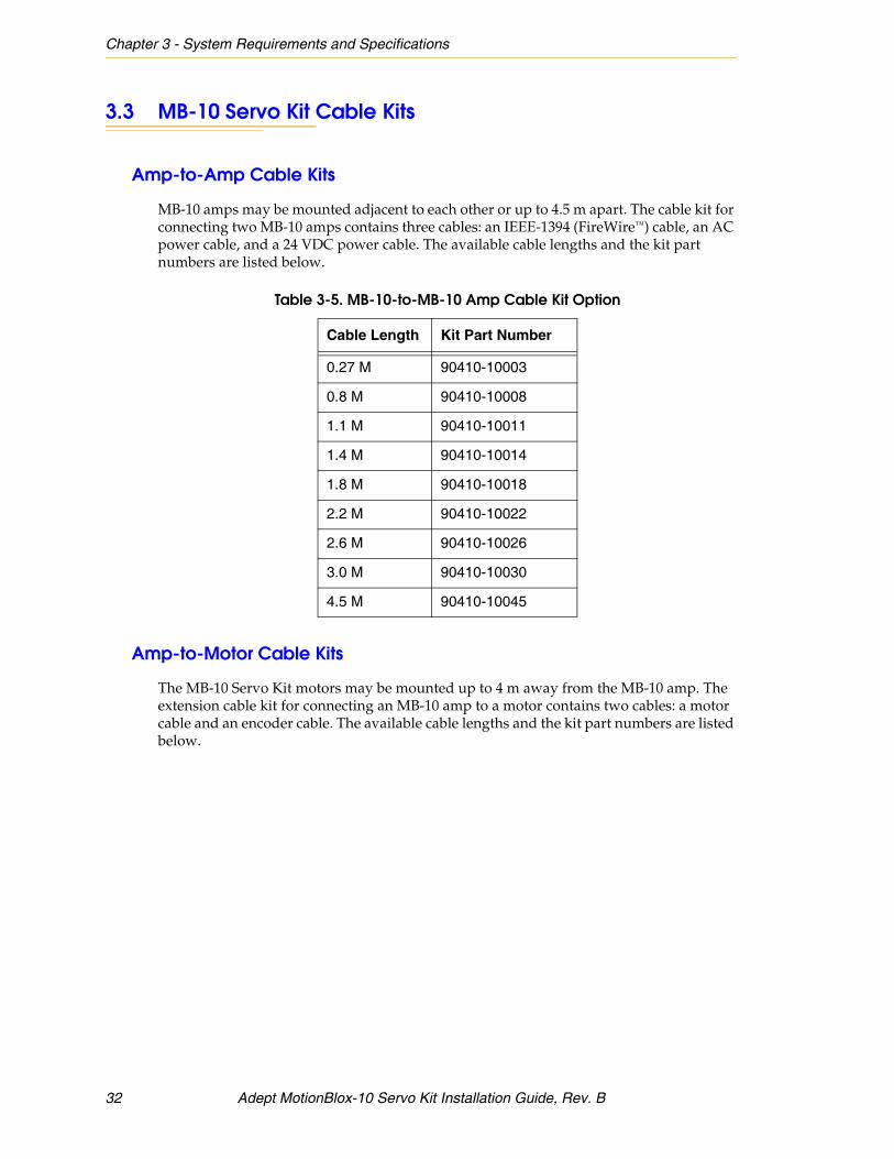
3.3 MB-10 Servo Kit Cable Kits
Amp-to-Amp Cable Kits
MB-10 amps may be mounted adjacent to each other or up to 4.5 m apart. The cable kit for connecting two MB-10 amps contains three cables: an IEEE-1394 (FireWire™) cable, an AC power cable, and a 24 VDC power cable. The available cable lengths and the kit part numbers are listed below.
Amp-to-Motor Cable Kits
The MB-10 Servo Kit motors may be mounted up to 4 m away from the MB-10 amp. The extension cable kit for connecting an MB-10 amp to a motor contains two cables: a motor cable and an encoder cable. The available cable lengths and the kit part numbers are listed below.
Table 3-5. MB-10-to-MB-10 Amp Cable Kit Option
Cable Length Kit Part Number
0.27 M 90410-10003
0.8 M 90410-10008
1.1 M 90410-10011
1.4 M 90410-10014
1.8 M 90410-10018
2.2 M 90410-10022
2.6 M 90410-10026
3.0 M 90410-10030
4.5 M 90410-10045
32 Adept MotionBlox-10 Servo Kit Installation Guide, Rev. B

MB-10 Servo Kit Cable Kits
Table 3-6. MB-10-to-Sigma II Motor Cable Kit Option
Cable Length Kit Part Number
1.1 M 90410-12011
1.4 M 90410-12014
1.8 M 90410-12018
2.2 M 90410-12022
2.6 M 90410-12026
3.0 M 90410-12030
3.5 M 90410-12035
4.0 M 90410-12040
Adept MotionBlox-10 Servo Kit Installation Guide, Rev. B 33


Adept Servo Kit Software 44.1 Overview
Before the system is operational, the Servo Kit motor must be configured to operate with the V+ motion control software. The basic steps are provided below.
NOTE: Before modifying your system configuration, back up your current system configuration.
1. Use the CONFIG_C program to append the appropriate device module(s) for the mechanism(s) in your system. See Section 4.2 for details.
2. Use the DC_SETUP program to configure the axis. See Section 4.3 for details. The steps performed are:
• Node mapping
• Loading the Module Joint file
• Calibrating the axis
3. Test the axis. See Section 4.4 for details.
4. Modify the default SPEC data file parameters. See Section 4.5 for details.
4.2 Using CONFIG_C to Append Device Modules
Perform the steps below to use the CONFIG_C program to append the appropriate device module(s) for the mechanism(s) in your system. Add a device module for each robot (each robot may contain multiple Servo Kits).
1. Connect all hardware associated with the controller and robot except the mechanical hardware attached to the Servo Kit motor.
2. To start up the CONFIG_C program, type the following at the prompt:
LOAD D:\UTIL\CONFIG_C
EXE 1 a.config_c
WARNING: The Servo Kit motor shaft should not be attached to any mechanism during the software configuration. After the configuration is complete and functionality of the motor has been verified, the intended mechanical device can be attached to the motor shaft.
Adept MotionBlox-10 Servo Kit Installation Guide, Rev. B 35
Chapter 4 - Adept Servo Kit Software
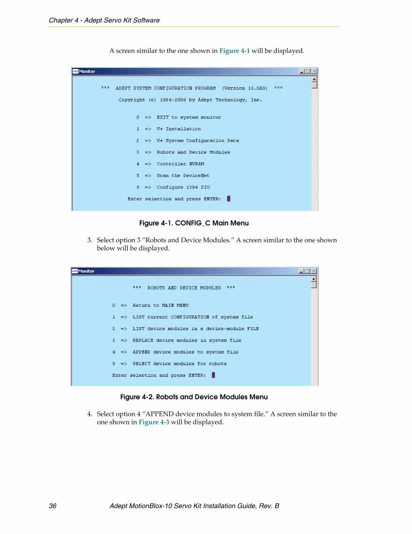
A screen similar to the one shown in Figure 4-1 will be displayed.
Figure 4-1. CONFIG_C Main Menu
3. Select option 3 “Robots and Device Modules.” A screen similar to the one shown below will be displayed.
Figure 4-2. Robots and Device Modules Menu
4. Select option 4 “APPEND device modules to system file.” A screen similar to the one shown in Figure 4-3 will be displayed.
36 Adept MotionBlox-10 Servo Kit Installation Guide, Rev. B

Using CONFIG_C to Append Device Modules
Figure 4-3. Append to Device Modules Screen
5. Make sure the device/disk/directory containing the device modules is selected. By default, the device modules are located in D:\SYSTEM\.
NOTE: The instructions below show how to append two different device modules: the JTS Coordinated-Joint-Control Robot Module and the Linear-Module Robot Module. In general, append the JTS Coordinated-Joint-Control Robot Module for applications requiring continuous turning capabilities (such as for driving conveyor belts); append the Linear-Module Robot Module for applications requiring linear (or point-to-point) motion control.
6. When prompted to enter the device-module file name:
• Type “JTS” (to select “JTS Coordinated-Joint-Control Robot Module”) and press ENTER.
Or
Adept MotionBlox-10 Servo Kit Installation Guide, Rev. B 37

Chapter 4 - Adept Servo Kit Software
• Type “LM” (to select “Linear-Module Robot Module”) and press ENTER.
After appending the selected device module, the program will step through the process of associating the device module to each robot that is configured for the controller.
7. When prompted to select robot 1, type “y” and press ENTER.
8. When prompted to select a device module to associate with robot 1, type the number beside the device module you appended to the system. For example, type “32” to associate the Linear-Module Robot Module with robot 1 (see Figure 4-4 for an example).
9. If you are not configuring another robot, type “n” and press ENTER when you see the prompt asking if you want robot 2.
Figure 4-4. CONFIG_C Selecting Device Modules to Associate with Robot Screen
10. Follow the on-screen prompts to continue.
11. Reboot the controller.
38 Adept MotionBlox-10 Servo Kit Installation Guide, Rev. B

Using DC_SETUP to Configure the Axis
4.3 Using DC_SETUP to Configure the Axis
1. After the controller reboots, type the following at the prompt.
load d:\util\dc_setup.v2
execute 1 a.dc_setup
The procedures for configuring an axis with the JTS Coordinated-Joint-Control Robot Module and Linear-Module Robot Module are different. There is a separate section in this manual for each module. The points below provide an overview of the two procedures.
• In practice, use DC_SETUP only once to configure the axis for the device module you appended using CONFIG_C.
• If you appended the JTS Coordinated-Joint-Control Robot Module, refer to the instructions in “Configuration for JTS Coordinated-Joint-Control Robot Module” on page 39.
• If you appended the Linear-Module Robot Module, refer to the instructions in “Configuration for LM Linear-Module Robot Module” on page 44.
Configuration for JTS Coordinated-Joint-Control Robot Module
The procedure below shows an example of how to configure an axis after the JTS Coordinated-Joint-Control Robot Module has been appended to and associated with your system.
After booting the controller and loading and executing DC_SETUP, a screen similar to the one shown in Figure 4-5 will be displayed.
Figure 4-5. DC_SETUP Main Menu (JTS Coordinated-Joint-Control Module)
Adept MotionBlox-10 Servo Kit Installation Guide, Rev. B 39

Chapter 4 - Adept Servo Kit Software
2. Select option 2 “Configure Adept robot/axis gadgets” and press ENTER. A screen similar to Figure 4-6 will be displayed.
Figure 4-6. DC_SETUP (JTS Coordinated-Joint-Control Module)
3. Select option 2 “SmartAmp/MotionBlox robot config.” and press ENTER. Type “Y” and press ENTER to load the robot configuration file. A screen similar to the one shown in Figure 4-7 will be displayed.
Figure 4-7. DC_SETUP (JTS Coordinated-Joint-Control Module)
4. Press ENTER. A screen similar to the one shown in Figure 4-8 will be displayed.
40 Adept MotionBlox-10 Servo Kit Installation Guide, Rev. B

Using DC_SETUP to Configure the Axis
Figure 4-8. DC_SETUP General Robot Config. (JTS Coordinated-Joint-Control Module)
5. Type “X” (or another one of the available axes displayed on screen) and press ENTER. A screen similar to the one shown in Figure 4-9 will be displayed.
Figure 4-9. DC_SETUP (JTS Coordinated-Joint-Control Module)
6. Press the SPACE bar to select the SmartServo device to which the Servo Kit motor is connected.When the LED on the MB-10 amp you want to configure flashes green/red, press ENTER to select it.
7. Type “Y” to configure this channel. A screen similar to the one shown in Figure 4-10 will be displayed.
Adept MotionBlox-10 Servo Kit Installation Guide, Rev. B 41

Chapter 4 - Adept Servo Kit Software
Figure 4-10. DC_SETUP Load Data for the Axis (JTS Coordinated-Joint-Control Module)
8. Select option 1 “Module Joint File” and press ENTER.
9. When prompted to enter the part number index for the selected axis, enter the five-digit part number of the motor you are configuring, or type “?” and press ENTER to display a list of the supported motor part numbers. If you enter “?”, a screen similar to the one shown in Figure 4-11 will be displayed.
42 Adept MotionBlox-10 Servo Kit Installation Guide, Rev. B

Using DC_SETUP to Configure the Axis
Figure 4-11. DC_SETUP (JTS Coordinated-Joint-Control Module)
A list of part numbers is displayed. The list includes the part numbers for the various types of Servo Kit motors, including Sigma 1 and 2 versions, 100 W, 200 W, 400 W, and 750 W models, and motors with and without brakes (for example, “92008 Adept Servo Kit 750 W w/ Brake Yaskawa Sigma 2 ““SGMAH””). The part number in the above example is “92008.”
10. After you enter the part number for the motor attached to the MB-10 amp or Servo Kit and press ENTER, select option 4 “Save ALL specifications to system disk” from the Distributed Control Setup main menu.
11. After saving the specification data to disk, exit from the DC_SETUP program.
12. Load and execute the SM_CAL.V2 program. To start up SM_CAL, type the following at the prompt:
load d:\util\sm_cal.v2
execute 1 a.sm_cal
Adept MotionBlox-10 Servo Kit Installation Guide, Rev. B 43

Chapter 4 - Adept Servo Kit Software
13. Follow the on-screen prompts to perform the calibration.
NOTE: Motor calibration will reset the absolute encoder multi-turn data to zero.
Configuration for LM Linear-Module Robot Module
The procedure below shows an example of how to configure an axis after the LM Linear-Module Robot Module has been appended to and associated with your system.
After booting the controller and loading and executing DC_SETUP, a screen similar to the one shown below will be displayed.
Figure 4-12. DC_SETUP Main Menu (LM Linear-Module Robot Module)
1. Select option 1 “Configure modules/Servo Kits/Hybrid.” A screen similar to the one shown below will be displayed.
44 Adept MotionBlox-10 Servo Kit Installation Guide, Rev. B

Using DC_SETUP to Configure the Axis
Figure 4-13. DC_SETUP Configure Modules/MotionBlox Menu
2. Select option 1 “Modules Quick Setup” and press ENTER. A screen similar to the one shown below will be displayed.
Figure 4-14. DC_SETUP General Robot Config. (LM Linear-Module Robot Module)
3. Type “X” (or another one of the available axes displayed on screen) and press ENTER. A screen similar to the one shown in Figure 4-15 will be displayed.
Adept MotionBlox-10 Servo Kit Installation Guide, Rev. B 45

Chapter 4 - Adept Servo Kit Software
Figure 4-15. DC_SETUP (LM Linear-Module Robot Module)
4. Press the SPACE bar to select the SmartServo device to which the Servo Kit motor is connected.When the LED on the MB-10 amp you want to configure flashes green/red, press ENTER to select it.
5. Type “Y” to configure this channel. A screen similar to the one shown in Figure 4-16 will be displayed.
Figure 4-16. DC_SETUP Load Data for the Axis (LM Linear-Module Robot Module)
6. Select option 1 “Module Joint File” and press ENTER.
7. When prompted to enter the part number index for the selected axis, enter the five-digit part number of the motor you are configuring, or type “?” and press ENTER to display a list of the supported motor part numbers. If you enter “?”, a screen similar to the one shown in Figure 4-17 will be displayed.
46 Adept MotionBlox-10 Servo Kit Installation Guide, Rev. B

Using DC_SETUP to Configure the Axis
Figure 4-17. DC_SETUP (LM Linear-Module Robot Module)
A list of part numbers is displayed. The list includes the part numbers for the various types of Servo Kit motors, including Sigma 1 and 2 versions, 100 W, 200 W, 400 W, and 750 W models, and motors with and without brakes (for example, “92008 Adept Servo Kit 750 W w/ Brake Yaskawa Sigma 2 ““SGMAH””). The part number in the above example is “92008.”
After you enter the part number for the motor attached to the MB-10 amp or Servo Kit and press ENTER, a screen similar to the one shown in Figure 4-18 will be displayed.
Adept MotionBlox-10 Servo Kit Installation Guide, Rev. B 47

Chapter 4 - Adept Servo Kit Software
Figure 4-18. DC_SETUP Current Configuration Screen
8. Press ENTER to continue on to the calibration step.
9. Follow the on-screen prompts to select each joint to calibrate the axes that calibrate to a hard stop. The absolute encoder position on these axes must be reset. This is accomplished by driving the axes to a hard stop, then resetting the absolute encoder to zero.
NOTE: Motor calibration will reset the absolute encoder multi-turn data to zero.
10. After you have calibrated the axis, you will be prompted to save the specification data to system disk. You must save the specification data and reboot the controller before the new configuration will be in effect.
4.4 Testing the Axis
The Servo Kit motor should now be operational. This can be verified by moving the axis using the optional pendant or writing a brief test program to exercise the motor.
NOTE: For continuous-turn applications, V+ requires a roll-over value. The default roll-over value is 360 degrees, which can be changed using the Motion Parameter menu in spec.v2.
WARNING: The Servo Kit motor shaft should not be attached to any mechanism during testing. After the configuration is complete and functionality of the motor has been verified, the intended mechanical device can be attached to the motor shaft.
48 Adept MotionBlox-10 Servo Kit Installation Guide, Rev. B

Testing the Axis
For continuous-turn applications, refer to the Adept website for information on the SPIN program command.
Below is a SPIN example program:
.PROGRAM rb.spin()
SELECT ROBOT = 1 ;JTS Robot number
ATTACH ()
SPEED 100 ALWAYS ;Define motion parameters
ACCEL 100, 100
COARSE ALWAYS
temp.speed[1] = 300 ;Set spin speed to 300 RPM
SPIN temp.speed[1] ;Spin motor
.END
Below is an example program showing how to exercise the motor.
.PROGRAM test()
DETACH ()
SELECT ROBOT = 1 ;user selects the targeted robot
ATTACH ()
SPEED 10 ALWAYS
ACCEL 100, 100
FINE ALWAYS
TIMER (1) = 0
FOR ii = 1 TO 10
MOVE #PPOINT(10) ;user selects the low motion limit
BREAK
MOVE #PPOINT(100) ;user selects the high motion limit
BREAK
END
TYPE “Total cycle time: “, TIMER(1), “ seconds.”
Adept MotionBlox-10 Servo Kit Installation Guide, Rev. B 49

Chapter 4 - Adept Servo Kit Software
4.5 Modifying the Default Parameters to Optimize Performance
The SPEC data files contain default parameters, which allow functionality of the Servo Kit to be tested. Servo Kit is capable of high-performance operation. However, the default parameters are set conservatively for safety considerations. It will be necessary to adjust these parameters for specific applications. These parameters can be adjusted using the SPEC utility. For details on using that program, and descriptions of all the data items, refer to the Adept SmartMotion Developer Guide.
50 Adept MotionBlox-10 Servo Kit Installation Guide, Rev. B


3011 Triad DriveLivermore, CA 94551925•245•3400P/N: 05851-000, Rev. B