adi disc brake systems - stealthproducts.com · 2/18/2019 · disc brake compatibility information...
TRANSCRIPT

INSTALLATION MANUAL
ADI Disc Brake SystemsInstallation Manual for HA-26 Disc Brake
Hub Assembly

Customer Satisfaction 1.0
Stealth Products strives for 100% customer satisfaction. Your complete satisfaction is important. Please contact us with feedback or to suggest changes that may help improve the quality and usability of our products. You may reach us at:
General
Read and understand all instructions prior to the use of the product. Failure to adhere to instructions and warnings in this document may result in property damage, injury, or death. Product misuse due to failure to adhere to the following instructions will void the warranty.
Immediately discontinue use if any function is compromised, if parts are missing or loose, or if any component shows signs of excessive wear. Consult with your supplier for repairs, adjustments or replacements.
Stealth Products, LLC 104 John Kelly DriveBurnet, TX 78611 Phone: (512) 715-9995 Toll Free: (800) 965-9229 Fax: (512) 715-9954 Toll Free: (800) 806-1225 [email protected] www.stealthproducts.com
i

Important Information!
All persons responsible for fitting, adjustment, and the daily use of devices discussed in these instructions must be familiar with and understand all safety aspects of the devices mentioned. In order for our products to be used successfully, you must:
• read and understand all instructions and warnings;• maintain our products according to our instructions on care and maintenance; and
• ensure devices are installed and adjusted by a trained technician.
All assemblies and configurations MUST be completed by a trained technician.
This manual contains instructions and statements meant to be followed by trained technicians.
Supplier Reference
Supplier: Telephone:Address:
Purchase Date:Model:
Important Information 2.0
ii

These installation instructions will guide you through your product’s options and possibilities.
Instructions are written with the expressed intent of use with standard configurations. They contain important safety and maintenance information, as well as describe possible problems that can arise during use. For further assistance, or more advanced applications, please contact your supplier or Stealth Products at (512) 715-9995 or toll free at (800) 965-9229.
Always keep the operating instructions in a safe place so they may be referenced as necessary.
All information, pictures, illustrations, and specifications are based on the product information that was available at the time of printing. Pictures and illustrations shown in these instructions are representative examples and are not intended to be exact depictions of the various parts of the product.
Ordering Documentation
You can download additional copies of this user manual by accessing the Stealth website (www.stealthproducts.com) and searching “ADI Disc Brake System Installation Manual” in the search bar at the top of the page.
Introduction 3.0
iii
CAUTION
These products are designed to be fitted, applied, and installed exclusively by a healthcare professional trained for these purposes. The fitting, application and installation by a non-qualified individual may result in serious injury.

Warranty 4.0
Our products are designed, manufactured, and produced to the highest of standards. If any defect in material or workmanship is found, Stealth Products, LLC will repair or replace the product at our discretion. Any implied warranty, including the implied warranties of merchantability and fitness for a particular purpose, shall not extend beyond the duration of this warranty. Stealth Products, LLC does not warrant damage due to, but not limited to:
• misuse, abuse, or misapplication of products; and/or• modification of products without written approval from Stealth Products, LLC.
Any lack or alteration of serial number, where applicable, will automatically void this warranty.
Stealth Products, LLC is liable for replacement parts only. Stealth Products, LLC is not liable for any incurred labor costs.
No person is authorized to alter, extend, or waive the warranties of Stealth Products, LLC.
Stealth Products, LLC warrants against failure due to defective materials or workmanship:
Covers: 180 daysHardware: 5 yearsElectronics: 3 years
In Case of Product Failure
In the event of product failure covered by our warranty, please follow the procedures outlined below:
1. Call Stealth Products at (512) 715-9995 or toll free at (800) 965-9229.
2. Request a Return Authorization (RA) form from the Returns Department and follow department documentation instructions.
iv

Table of Contents 5.0
v
.
1.0 Customer Satisfaction ................................................................................. i
2.0 Important Information ............................................................................... ii
3.0 Introduction ............................................................................................... iii
4.0 Warranty ..................................................................................................... iv
5.0 Table of Contents ........................................................................................ v
6.0 Warning Labels .......................................................................................... vii
6.1 Warning Labels ...........................................................................................................vii
6.2 Limited Liability ...........................................................................................................vii
6.3 Testing ............................................................................................................................vii
7.0 Design and Function ................................................................................... 1
7.1 Intended Use .................................................................................................................1
7.2 Features ...........................................................................................................................1
8.0 Compatibility ............................................................................................... 2
8.1 Disc Brake Compatibility Information ..................................................................2
8.2 Wheel Compatibility ...................................................................................................2
8.3 Chair Compatibility......................................................................................................3
9.0 Parts and Accessories ................................................................................. 4
9.1 Disc Brake Package Components ..........................................................................4
9.2 HA-26 Disc Brake Kit...................................................................................................4
9.3 Brake and Lever Torque Specifications ................................................................6
9.4 Brake Lever Kits.............................................................................................................7
9.41 Variable Lever Kit................................................................................................7
9.42 Para Lever Kit .......................................................................................................9
9.43 Variable Lever Kit............................................................................................. 11

Table of Contents 5.0
vi
10.0 Installation Information .........................................................................13
10.1 Preparations .............................................................................................................13
10.2 Tools.............................................................................................................................13
10.3 Installation Plan ....................................................................................................... 13
10.4 Brake Installation Instructions: HA-26 ............................................................ 14
10.5 Lever Kit Installation Instructions ..................................................................... 19
10.51 Variable Lever Kit Installation Instructions ........................................ 19
10.52 Para Lever Kit Installation Instructions ................................................ 26
10.53 Attendant Lever Kit Installation Instructions .................................... 34
11.0 Caliper Adjustments ...............................................................................42
12.0 First-Time Use .........................................................................................44
12.1 Dealer Assistance ................................................................................................... 44
12.2 User Testing ..............................................................................................................44
12.3 Conditions of Use ................................................................................................... 44
13.0 Maintenance ............................................................................................45
13.1 Cleaning .....................................................................................................................45
13.2 Disinfecting ...............................................................................................................45
13.3 General Maintenance ............................................................................................ 45
14.0 Notes ........................................................................................................46

Warning Labels 6.0
Warning Labels 6.1
Warnings are included for the safety of the user, client, operator, and property. Please read and understand what the signal words DANGER, WARNING, CAUTION, NOTICE and SAFETY mean, and how they could affect the user, those around the user, and property.
Limited Liability 6.2
Stealth Products, LLC accepts no liability for personal injury or damage to property that may arise from the failure of the user or other persons to follow the recommendations, warnings, and instructions in this manual. Stealth Products, LLC does not hold responsibility for final integration of final assembly of product to end user. Stealth Products, LLC is not liable for user death or injury.
Testing 6.3
Initial setup and driving should be done in an open area free of obstacles until the user is fully capable of driving safely.
DANGER Identifies an imminent situation which, if not avoided, may result in severe injury, death, and/or property damage.
WARNING Identifies a potential situation which, if not avoided, may result in severe injury, death, and/or property damage.
CAUTIONIdentifies a potential situation which, if not avoided, may result in minor to moderate injury and/or property damage.
NOTICE Identifies important information not related to injury, but possible property damage.
SAFETYIndicates steps or instructions for safe practices, reminders of safe procedures, or important safety equipment that may be necessary.
vii

Design and Function 7.0
1
Features 7.2
ADI’s disc brake systems offer three different types of brake actuation methods:
• Variable
• Para lever
• Attendant lever
Additionally, ADI’s disc brake systems offer model-specific 0°, 2°, and 4° camber degree options, as well as direct-mount or spline-insert options for select configurations.
Intended Use 7.1
ADI’s disc brake systems are intended to be used as brake systems for manual wheelchairs. They are designed to attach to the camber tube region of the wheelchair and slow/stop the wheelchair upon brake lever activation.
Disc brakes offer a positive lock independent of tire pressure/wear, reduce upper body fatigue, augment user control, and afford users of all physical abilities near-effortless braking abilities.
Requiring substantially less pressure to activate (1-2lbs of pressure versus roughly 20lbs required for wheel-lock brake systems), disc brake systems are ideal for users with impaired trunk control and/or nonfunctional tricep strength. Additionally, ADI’s systems offer multiple brake lever options and configurations tailored to meet the needs of users with a) right, left or bilateral upper extremity weakness; b) impaired hand control; or c) users who have undergone a right or left upper extremity amputation.
Compatibility 8.0
2
Disc Brake Compatibility Information 8.1
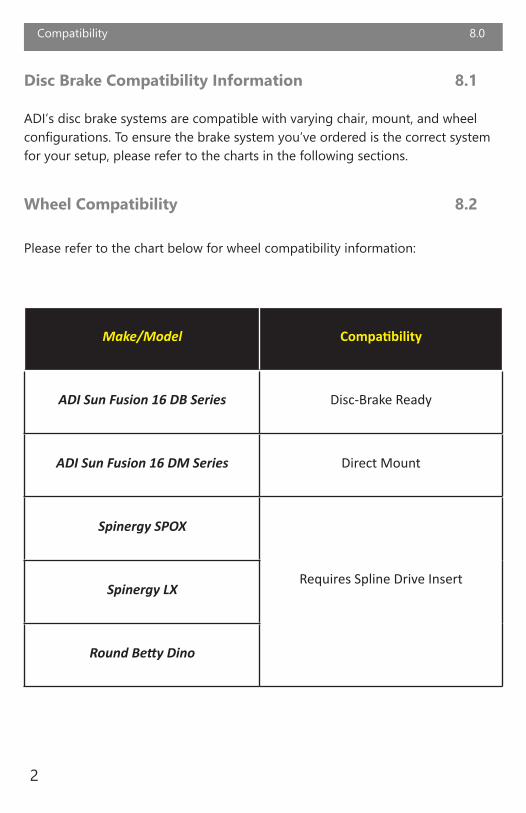
ADI’s disc brake systems are compatible with varying chair, mount, and wheel configurations. To ensure the brake system you’ve ordered is the correct system for your setup, please refer to the charts in the following sections.
Wheel Compatibility 8.2
Please refer to the chart below for wheel compatibility information:
Make/Model Compatibility
ADI Sun Fusion 16 DB Series Disc-Brake Ready
ADI Sun Fusion 16 DM Series Direct Mount
Spinergy SPOX
Requires Spline Drive InsertSpinergy LX
Round Betty Dino

Compatibility 8.0
3
Brake Kit Chair Make Chair Model Camber/Mount Options
HA-10
Motion Composites
Apex
0°, 2°, 4° camber tilt
Sunrise/QuickieZippie
Q7
TiLite
Twist
Zr
ZRA
TR
TRA
TR3
Aero Z
Aero T
HA-12Ki Mobility
Rogue
HA-14 Little Wave
HA-18 Invacare Solara
Direct MountHA-26 Ki Mobility Focus
HA-34 Sunrise/Quickie Iris
HA-42 Pride Litestream
Chair Compatibility 8.3
Please refer to the chart below for chair compatibility information:

Parts and Accessories 9.0
4
Disc Brake Package Components 9.1
This disc brake package contains a brake kit and a lever kit.
HA-26 Disc Brake Kit 9.2
Below is a basic diagram of components included with the HA-26 disc brake kit:
HA-26 DISC BRAKE KIT

Parts and Accessories 9.0
5
KEY CALIPER COMPONENTS
BASIC CALIPER COMPONENTS
ID Part Description Qty.
1 Caliper Compresses brake pad 1
2 Cable Input Ferrule Houses brake cable 1
3 Moving Arm (Caliper) Engages brake cable 1
Item No. Part Oty.
1 Caliper (Left) 1
2 Tall Brackets 2
3 Ki Focus Brackets 2
4 Torx Cap Screws (M5x0.80 X 10mm) 12
5 Rotor Discs 2
6 Threaded Axle Receiver (.750) 2
7 Hex Nuts (3/4”-16 thread) 2
8 Cap Screws (6”; 1/2”-20 thread) 2
9 Lock Nuts (1/2”-20 thread) 2
10 Caliper (Right) 1
11 Cap Screws (M6x1 X 16mm) 4
12 Flat Washers (M6) 4
13* Mounting Bracket 2
* Note: Either Part 2 or Part 13 will be installed according to fit and assembly requirements.

Parts and Accessories 9.0
6
Hardware Torque Specifications
6mm 8.7 N•m
5mm 5.1 N•m
4mm 2.6 N•m
10-32 31.7 lb-in
Brake and Lever Torque Specifications 9.3

Parts and Accessories 9.0
7
Brake Lever Kits 9.4
ADI’s disc brake packages will include a Variable, a Para, or an Attendant brake lever kit. Check to ensure you have received the correct lever kit before installation.
Variable Lever Kit 9.41
Part Description Qty.
1 Lever Adjustment Bar Attaches lever assembly to frame clamp 1
2 Cable Block Seats and secures brake cables 1
3 Cable Housing Clamp Seats and secures cable housing 1
4 Cable Block Set Screws Tighten to secure brake cables 2
5 Cable Housing Clamp Screws Tighten to secure cable housing 2
VARIABLE LEVER ASSEMBLY

Parts and Accessories 9.0
8
Part Description Qty.
1 Brake Cables Connect disc brake calipers to lever system 2
2 MTB Brads Cap and help seat brake cables 2
3 Metal End Caps (Cables) Crimped to prevent brake cable wear/unraveling 2
4 Brake Cable Housing Houses and protects brake cables 2
5 Metal End Caps (Housing) Cap and help seat cable housing 2
VARIABLE LEVER BRAKE CABLES AND HOUSING

Parts and Accessories 9.0
9
Para Lever Kit 9.42
PARA LEVER ASSEMBLY
Part Description Qty.
1 Lever Engages brake system 2
2 Lever Adapter Insert Enables cane compatibility 2
1
2

Parts and Accessories 9.0
10
PARA LEVER BRAKE CABLES AND HOUSING
Part Description Qty.
1 Brake Cables Connect disc brake calipers to lever system 2
2 Brake Cable Housing Houses and protects brake cables 2
3 MTB Brads Cap and help seat brake cables 2
4 Metal End Caps (Cables) Crimped to prevent cable wear/unraveling 2
5 Metal End Caps (Housing) Cap and help seat cable housing 4

Parts and Accessories 9.0
11
Attendant Lever Kit 9.43
ATTENDANT LEVER ASSEMBLY
Part Description Qty.
Lever Engages brake system 2

Parts and Accessories 9.0
12
ATTENDANT LEVER BRAKE CABLES AND HOUSING
Part Description Qty.
1 Brake Cables Connect disc brake calipers to lever system 2
2 Brake Cable Housing Houses and protects brake cables 2
3 MTB Brads Cap and help seat brake cables 2
4 Metal End Caps (Cables) Crimped to prevent cable wear/unraveling 2
5 Metal End Caps (Housing) Cap and help seat cable housing 4

Installation Information 10.0
13
Preparations 10.1
Only a qualified service technician may install ADI disc brake systems.
WARNING
An incorrect installation of the brake system or its accessories may cause damage to the hardware and/or injury to the user.
Tools 10.2
Use the proper tools to install and adjust the ADI disc brake system to the desired position for the user. Ensure all torque specifications are followed.
Installation Plan 10.3
Set up an installation plan before beginning the installation. This plan should take into account:
• where the brake actuator lever will be placed;• how the disc brake system will be operated; and• the amount of necessary clearance for other hardware and accessories.
CAUTION
The use of improper tools may damage the device. Not tightening to the torque specification can cause components to fail or cause the user discomfort.
CAUTION
Any connection must always be secured with all delivered screws. Only use the screws provided in the package.

Installation Information 10.0
14
Brake Installation Instructions: HA-26 10.4
REQUIRED TOOLS:• Crescent wrench• 3/4” (17mm) wrench• Hex keys: 3mm, 4mm, 5mm, 1/4”• Cable cutters• T27 Torx wrench (star-shaped)
Step 1: Use a tape measure to take original measurements of the wheelchair’s delivered arrangements.

Installation Information 10.0
15
Step 2: Working one side at a time, remove each threaded axle receiver and each corresponding OEM bolt.
Step 3: Slide tall brackets into place; loosely replace OEM hardware and axle receivers.
Axle receiver
OEM bolt
Bracket

Installation Information 10.0
16
Step 4: Bolt the “U”-shaped caliper brackets to the tall brackets.
“U”-shaped caliper bracket
Step 5: Adjust the threaded axle receiver to the measurement shown for correct disc-to-caliper alignment, then tighten the corresponding lock nuts.
2 or 3 threads exposed

Installation Information 10.0
17
Step 6: Tighten the OEM bolt.
Step 7: Using the Torx cap screws provided, bolt the rotor discs to the wheels.
Step 8: Simultaneously, slide the removed caliper main body around the rotor and slide the wheel into position on the axle. When in place, tighten the axle bolts using the two 3/4”-16 hex nuts provided.
Note: Calipers are aligned to the rotor discs by the two silver caliper bolts opposite one another

Installation Information 10.0
18
Step 9: Adjust the brake pads. Refer to the Caliper Adjustments section when making adjustments.

Installation Information 10.0
19
Lever Kit Installation Instructions 10.5
Each disc brake package will include a brake lever kit specified when the brake package was ordered.
Variable Lever Kit Installation Instructions 10.51
Step 1: Identify and remove the wheelchair’s OEM wheel lock, leaving the existing frame clamp attached.
(Note: Perform these steps after the disc brake hub assemblies have been installed and adjusted to the wheelchair.)
REQUIRED TOOLS:• Cable cutters• Zip ties• Hex keys: 3/32”, 1/8”, 3/16”, 4mm, 5mm

Installation Information 10.0
20
Step 2: Insert the lever adjustment bar into the existing frame clamp; adjust position as necessary.• It is recommended that after the lever is mounted, it should not extend past the chair’s
frame when engaged fully forward.
Step 3: When the lever adjustment bar is in the desired position, use a hex key to tighten the screws on the frame clamp.

Installation Information 10.0
21
Step 4: Determine the amount of cable/housing necessary to reach from the upper hole in the lever handle to the cable input ferrules on the same-side and opposite-side calipers.• The cable attaching the lever to the opposite-side caliper should make a gentle “S”
shape along the underside of the chair’s seat, allowing some slack for adjustments.
Step 5: Cut two lengths of cable and housing, ensuring the cuts are clean and free of obstructions.• Cut the tubing to the same length. This will provide equal drag and will allow the user
to easily switch the side on which the lever is mounted, if necessary. (Note: The Variable Lever comes preassembled for the side specified on the order. To switch sides, it will be necessary to disassemble the lever.
• Check that the cuts are clean and the cable housing is free of obstructions that can drag on the cable.
• If necessary, use zip ties to secure the cables/housing to the chair. The cable/housing attaching the lever to the same-side caliper should meet and run roughly parallel to the cable/housing attaching the lever to the opposite-side caliper.
• To gauge the necessary length of housing, gently crimp a metal end cap to one end of the housing and insert this crimped end into the adjustable cable input ferrule on the caliper. (Do this with both the same-side and the opposite-side calipers, ensuring equal cable length on both sides.)

Installation Information 10.0
22
Step 6:
6a) Run one end of each cable through the front of the holes in the cable block, pulling the cable until the ends with MTB brads are fully seated in the cable block.
6b) When the cables are fully seated, use a 3/32” hex key to tighten the set screws on the cable block.

Installation Information 10.0
23
Step 7:
7a) Feed the ends of each cable into the housing, leading the cable through the cut ends of the housing first.
7b) Place the housing clamp over the cables and insert the cut ends of the cable housing into the slots on the housing clamp.
7c) Secure the housing clamp screws with a 3/32” hex key.

Installation Information 10.0
24
Step 8: Feed the cables through the housing and into the cable input ferrules on both calipers.• Ensure the lever handle is pulled all the way back in the neutral position.
• The ends of the cables should be fully seated in the cable inputs.
Step 9:
9a) Pull the cable through the input, removing all slack; feed the cable through the clamps on each caliper’s moving arm.
9b) Use a 4mm hex key to tighten the caliper clamp screw, locking the cable to the clamps.

Installation Information 10.0
25
Step 10: Using wire cutters, cut away excess cable; cap and crimp the cable ends to prevent cable wear and/or unraveling.
Step 11:
11a) Test the brake system before use, ensuring the system locks and releases fully and easily.
11b) To achieve full and even braking through the entirety of the lever action, first adjust the calipers and brake pads (see Caliper Adjustments section of this manual). Minor adjustments to cable tension may be made to equalize tension.• The first lever click forward (Click 1) should have slight drag while still allowing the
wheels to roll.• The fourth lever click forward (Click 4) should have strong drag while still allowing
the wheels to be moved.• Click the lever fully forward (Click 5) should lock both wheels fully.

Installation Information 10.0
26
Para Lever Kit Installation Instructions 10.52
REQUIRED TOOLS:• Side cut pliers• Hex keys: 3/16”, 4mm, 5mm• #2 Phillips screwdriver
Step 1: Using a #2 Phillips screwdriver, attach the 7/8”-to-3/4” adapter to the lever’s clamping section.
(Note: Perform these steps after the disc brake hub assemblies have been installed and adjusted to the wheelchair.)
7/8”-to-3/4” adapter
• Ensure the upper pivot point is toward the rear of the mechanism before tightening the top cap.
• Check lever action for smooth operation.

Installation Information 10.0
27
Step 2: Identify and remove the chair’s OEM wheel lock, leaving the existing frame clamp attached.
Step 3:
3a) Insert the 7/8”-to-3/4” adapter into the OEM frame clamp; adjust position as necessary.
3b) When the lever is in the desired position, use a hex key to tighten the screws on the frame clamp.

Installation Information 10.0
28
Step 4: Determine the amount of cable/housing necessary to attach the lever to the cable input ferrule on the caliper.
• The cable attaching the lever to the opposite-side caliper should make a gentle “S” shape along the underside of the chair’s seat, allowing some slack for adjustments.
• To gauge the necessary length of housing, gently crimp a metal end cap to one end of the housing and insert this crimped end into the cable input ferrule on the caliper. Then route the housing to the lever input and mark the length to ensure a clean, clear housing cut.

Installation Information 10.0
29
Step 5: Cut a length of housing, ensuring the cuts are clean and free of obstructions that may drag on the cable.
Step 6: Gently crimp a metal end cap to both ends of the housing.
Installation Information 10.0
30
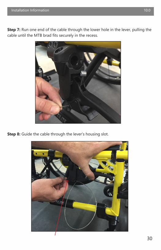
Step 7: Run one end of the cable through the lower hole in the lever, pulling the cable until the MTB brad fits securely in the recess.
Step 8: Guide the cable through the lever’s housing slot.

Installation Information 10.0
31
Step 9: Feed the cable through the cable housing, checking for smooth operation.
Step 10: Run the cable through the caliper’s cable input ferrule and down through the slot on the caliper’s clamping arm, ensuring the cable housing is fully seated in the cable input ferrule.

Installation Information 10.0
32
Step 11: Pull to remove all slack from the cable; tighten clamp screws with a 4mm hex key.
Step 12: Cut away any excess cable, approximately 6” to 1’.
Installation Information 10.0
33
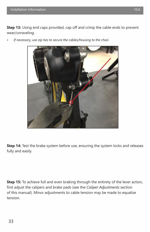
Step 13: Using end caps provided, cap off and crimp the cable ends to prevent wear/unraveling.
• If necessary, use zip ties to secure the cables/housing to the chair.
Step 14: Test the brake system before use, ensuring the system locks and releases fully and easily.
Step 15: To achieve full and even braking through the entirety of the lever action, first adjust the calipers and brake pads (see the Caliper Adjustments section of this manual). Minor adjustments to cable tension may be made to equalize tension.

Installation Information 10.0
34
Attendant Lever Kit Installation Instructions 10.53
REQUIRED TOOLS:• Side cut pliers• Hex keys: 3/16”, 4mm, 5mm• #2 Phillips screwdriver• Box cutter
(Note: Perform these steps after the disc brake hub assemblies have been installed and adjusted to the wheelchair.)
Step 1: Dual-locking attendant levers come in two cane diameters: 7/8” and 1” Ensure you have the correct diameter for your application by measuring the cane diameter at the lever’s desired location.

Installation Information 10.0
35
Step 3:
3a) Attach the brake lever clamp on the wheelchair handle.
3b) When the lever is in the desired location, use a #2 Phillips screwdriver to tighten the clamp screws and secure the lever to the handle.
Step 2: Determine the desired mounting locations for the levers. Use a box cutter to cut away any obstructive padding or grips and ensure space for the lever handle.

Installation Information 10.0
36
Step 4: Determine the amount of cable/housing necessary to attach the lever to the cable input ferrule on the caliper.
• Both cables should be of as equal a length as possible to ensure equal cable drag and lever operation.
• To gauge the necessary length of housing, gently crimp a metal end cap to one end of the housing and insert this crimped end into the cable input ferrule on the caliper. Then route the housing to the lever input and mark the length to ensure a clean, clear housing cut.

Installation Information 10.0
37
Step 5: Cut a length of cable housing, ensuring the cuts are clean and free of obstructions that may drag on the cable.
Step 6: Gently crimp a metal end cap to both ends of the cable housing.

Installation Information 10.0
38
Step 7: Run one end of the cable through the lower hole in the lever, pulling the cable until the MTB brad fits securely in the recess.
Step 8: Feed the cable through the housing, checking for smooth operation.

Installation Information 10.0
39
Step 9: Run the cable through the caliper’s cable input ferrule and down through the slot on the caliper’s clamping arm, ensuring the cable housing is fully seated in the cable input ferrule.

Installation Information 10.0
40
Step 10: Pull to remove all slack from the cable; tighten clamp screws with a 4mm hex key.
Step 11: Cut away any excess cable, approximately 6” to 1’.

Installation Information 10.0
41
Step 12: Cap and crimp the cable ends to prevent wear/unraveling.
• If necessary, use zip ties to secure the cables/housing to the chair.
Step 14: Test the brake system before use, ensuring the system locks and releases fully and easily.
Step 15: To achieve full and even braking through the entirety of the lever action, first adjust the calipers and brake pads (see the Caliper Adjustments section of this manual). Minor adjustments to cable tension may be made to equalize tension.

11.0
42
Caliper Adjustments
Caliper Adjustments 11.0
This section details caliper components, and lists the tools and steps required to adjust them.
CALIPER COMPONENTS AND REQUIRED TOOLS
REQUIRED TOOLS:• 8mm open-end wrench• Hex keys: 2.5mm, 3mm, 4mm, 5mm• Two business cards• Snap-ring pliers

Caliper Adjustments 11.0
43
Calipers have several points of adjustment:
• Inner Pad Adjustor• Outer Pad Adjustor• Attachment Bolts• Cable Input Ferrule
CALIPER ADJUSTMENT INSTRUCTIONS
Step 1: Begin by checking that the moveable arms on both calipers are at a full open position when the brake is in the neutral position with little to no slack in the cable system.
Step 2: Loosen the attachment bolts with a 5mm hex key. Position the caliper so there is an equal gap between pads on either side of the disc.
Step 3: Attachment bolts also adjust the caliper angle. Ensure the disc is not askew in relation to the pads before tightening the atachment bolts.
Step 4: Loosen the outer pad set screw with a 2.5mm hex key before adjusting the brake pads.
Step 5: Slide one business card on either side of the disc between the pads. Carefully, tighten the inner adjustment and outer adjustment mechanisms a little at a time until the business cards are tight against the disc. Loosen incrementally, just enough to slide the cards out.
Step 6: Engage the brake levers, checking for full wheel braking. The wheels should lock smoothly and easily, without significant force applied to the lever. Make slight adjustments to the outer pad locking screw with a 5mm hex key to achieve these settings.
Step 7: When full braking with minimal lever effort has been achieved, use a 2.5mm hex key to tighten the outer pad locking screw. (Note: During this adjustment, the brakes must be fully engaged.)
Step 8: Test the brake system using a series of hard stops and slow braking. Make note of any veering or tracking caused by the brakes. Adjust this tracking by turning the cable input ferrules. When tracking is even, after several tests, tighten the cable input nut with an 8mm hex key.

First-Time Use 12.0
Dealer Assistance 12.1
During first-time use by the client, it is advised that the dealer or service technician not only assembles the product, but also explains the configuration of user positioning to the customer (the user and/or the attendant). If needed, the dealer can make final adjustments.
Conditions of Use 12.3
ADI disc brake systems are intended for use as installed by the dealer, in accordance with the installation instructions in this manual.
• The foreseen conditions of use are communicated by the dealer or service technician to the user and/or attendant during the first-time use.
• If the usage conditions change significantly, please contact your dealer or a qualified service technician to avoid unintended damage.
User Testing 12.2
It is important that the customer is fully aware of the installation of the disc brake system, how to operate it, and how it can be adjusted according to the needs of the client. A dealer should explain and demonstrate the necessary installation steps, and should explain the functions of the device’s components.
Have the user test the position of the brake actuator lever(s).
• Is the hardware in the proper position for the client?• Can the user safely operate all controls with minimal effort?
If necessary, make adjustments to the positioning. Explain potential problems to the customer and how best to address them.
44

45
Maintenance 13.0
Cleaning 13.1
Use a soft, damp cloth to clean the hardware and its components. Ensure all cleaners are approved for finished steel and aluminum.
Disinfecting 13.2
Gently wipe the hardware with a soft cloth dampened with a household disinfectant.
General Maintenance 13.3
These care and guideline instructions will keep the hardware in good condition for a longer period of time and will prevent damage:• Check and re-tighten all fasteners to the proper torque specifications on a regular
basis. Reference the installation manual to find proper torque specifications.
• Check components for any breakdown.
• Repair or replace parts as needed.
• Gently remove dust and dirt from hardware with a soft, damp cloth.
SAFETY Replace or repair parts as needed.
NOTICE
Improper installation or alteration of the hardware included in ADI disc brake systems will void the warranty.

Notes 14.0
46

Notes 14.0
47

Stealth Products, LLC. • [email protected] • www.stealthproducts.com+1(800) 965-9229 | +1(512) 715-9995 | 104 John Kelly Drive, Burnet TX 78611
Revision Date 2019-02-22P147D592 -- HA-26 Installation Manual