adjustable fan controller -...
TRANSCRIPT

Adjustable Fan Controller for the Mazda6Scott Burton January 2008
With technical advice provided by ShaDrag and DJQuick of Mazda6Club
The Mazda6 engine management computer is tuned to optimize the operation of the engine onregular octane gas. This tuning results in retarding the spark timing as the engine coolanttemperature reaches about 208 degrees. (According to OBD data readings on my car.) With thestandard thermostat calibration, engine temperatures will frequently rise above 210 degrees andspark timing will be retarded by the ECU resulting in sluggish low RPM acceleration. Thismodification provides a secondary input for the fan control circuit to enable the operation of theradiator cooling fans at lower temperatures. The early activation of the fans helps to reduce enginecoolant temperatures and maintain advanced spark timing for prompt throttle response.
Overview of the Adjustable Fan Controller:
The connections and controls on theAdjustable Fan Controller consist of:1. Adjustable Fan Controller.2. Turn-on temperature adjustment.3. Chassis ground connection.4. +12 Volt supply wire.5. Fan control ground wire.6. Remote thermal sensor plug.7. Mounting bracket.
Tools Required:• Pair of pliers, small regular screwdriver• 10mm, 13mm, & 14mm wrenches.
The Adjustable Fan Controller.
Installation Overview:
These installation directions are for both V6and I4 Mazda6 vehicles with either thecoolant or block thermal sensor. Be sure youare using the correct section of instructionsfor your car. Please make note of the differentparts to be installed depending on your carand sensor:
A) +12 Volt supply lead. (All models)
B) Heavy black fan ground lead. (V6 only)
C) Blue Fan Relay Lead (I4 only)
D) Coolant Thermal Sensor.
E) Block Thermal Sensor.
V6 & I4 Connectors with Thermal Sensors Options
2/10/08 Page 1 of 9 Cordova MotorSports

Thermal Sensor Installation:1. Preparation:
If you have a 2.3L, remove the engine cover and set aside. For future reference, identify and locate the(1) throttle body, (2) relay panel, and (3) a readily available chassis ground screw on your V6 or I4engine bay.
Next, follow steps 2a, 2b, or 2c for the appropriate Thermal Sensor you have purchased.
Mazda6s Engine CompartmentMazda6i Engine Compartment
2a. Installing the Coolant Thermal Sensor:
The Coolant Thermal Sensor is designed tomonitor the temperature of the coolantcirculating in the throttle body coolant lines.To install the coolant sensor:1. Remove the coolant line from the throttle
body inlet coolant pipe.2. Attach the 3” section of hose to the throttle
body coolant pipe. Slip the 2 hose-clampson to the hose.
3. Press the Coolant Thermal Sensor onto theopen end of the small hose section.
4. Attach the lose coolant line to the other sideof the Coolant Thermal Sensor using theremaining hose clamp..
Note: If the throttle body coolant bypass hasbeen done, the Coolant Thermal Sensor canbe used to join the 2 coolant lines.
Coolant Thermal Sensor Installation(2.3L shown, V6 is similar.)
2/10/08 Page 2 of 9 Cordova MotorSports
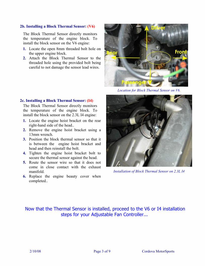
2b. Installing a Block Thermal Sensor: (V6)
The Block Thermal Sensor directly monitorsthe temperature of the engine block. Toinstall the block sensor on the V6 engine:1. Locate the open 8mm threaded bolt hole on
the upper engine block.2. Attach the Block Thermal Sensor to the
threaded hole using the provided bolt beingcareful to not damage the sensor lead wires.
Location for Block Thermal Sensor on V6.
2c. Installing a Block Thermal Sensor: (I4)The Block Thermal Sensor directly monitorsthe temperature of the engine block. Toinstall the block sensor on the 2.3L I4 engine:1. Locate the engine hoist bracket on the rear
right-hand side of the head..2. Remove the engine hoist bracket using a
13mm wrench.3. Position the block thermal sensor so that it
is between the engine hoist bracket andhead and then reinstall the bolt.
4. Tighten the engine hoist bracket bolt tosecure the thermal sensor against the head.
5. Route the sensor wire so that it does notcome in close contact with the exhaustmanifold.
6. Replace the engine beauty cover whencompleted..
Installation of Block Thermal Sensor on 2.3L I4
Now that the Thermal Sensor is installed, proceed to the V6 or I4 installationsteps for your Adjustable Fan Controller...
2/10/08 Page 3 of 9 Cordova MotorSports

Adjustable Fan Controller Installation on the V6:
1. On the V6 engine, the following componentsare needed for installation:
A - Adjustable Fan Controller withmounting bracket.
B - Thin red +12V power lead. C - Thick black fan ground lead & tap.
V6 Installation Components
2. Remove the cover from the relay panel andidentify the 'AC Relay' using the diagram on theunderside of the cover. (This relay is used as aconvenient source for +12V power.) Removethe AC Relay from its socket and locate theupper right relay contact. Push the 1/4" exposedend of the thin red +12V power lead into upperright contact slot so that the exposed wiretouches the relay socket contact. The contactsare arranged as shown below with the RED lineindicating the desired relay contact slot: __ | | __Replace the AC Relay to secure the +12Vpower lead in the socket. Route the red wire outthe rear left corner of the relay panel.
Connect the +12V power lead to the AC Relay
2/10/08 Page 4 of 9 Cordova MotorSports

3. Locate the power connector for the radiator fan module and peel back a few inches of the cablehousing to expose the thick black fan ground wire. Use the supplied yellow scotch-lock to tap the thickblack ground wire lead onto this wire as shown below. Make sure the connector gets plugged back in.
Locate the main plug to the fan control module Add the scotch-lock tap to the fan ground lead
4. Mount the Adjustable Fan Controller usingthe right hold-down bolt for the fuse box.Remove the stock bolt and replace it using theprovided 10mm bolt and two washers. Usingthe black washer on the bottom, and the silverwasher on top, re-install the bolt through themouning bracket and back into the fuse boxhold-down. Loosen the chassis ground boltlocated on the shock tower and slide the yellowlug connector under the ground bolt. Retightenthe chassis ground and fuse box hold-downbolts.
Now connect the red power wire to the +12Vpower lead previously connected to the relaypanel. Attach the white connector to theprevously installed thermal sensor plug.Connect the remaining wire to the Fan Controlmodule wire tap added in step 3.
Mount the controller using the new bolt and washers and attach the ground lug
5. Replace the relay panel cover and tuck the loose wires down in the space between the battery and relaypanel. Using a small screwdriver, rotate the fan turn-on adjustment to the full clockwise (coolest) setting.Start the engine and let it run for 5-10 minutes with the AC off. When the engine reaches roughly 120Fthe Red LED should illuminate and the radiator fan should operate. Turning the adjustment counter-clockwise will turn the LED and fan off until the engine temperature rises to the new setting. A settingthat supports on-off cycling of the fan should be possible using the coolant thermal sensor.
2/10/08 Page 5 of 9 Cordova MotorSports

Adjustable Fan Controller Installation on the I4:
1. Installation on a Mazda6i will require thefollowing components:
A - The adjustable fan controller B - Short blue fan relay lead C - Short red +12V power lead.
2. Remove the cover from the relay panel andidentify the 'Fan Relay' and the 'AC Relay'. Thelocation of these relays is diagramed on theunderside of the relay panel cover.
Location of Fan and AC Relays.
2/10/08 Page 6 of 9 Cordova MotorSports
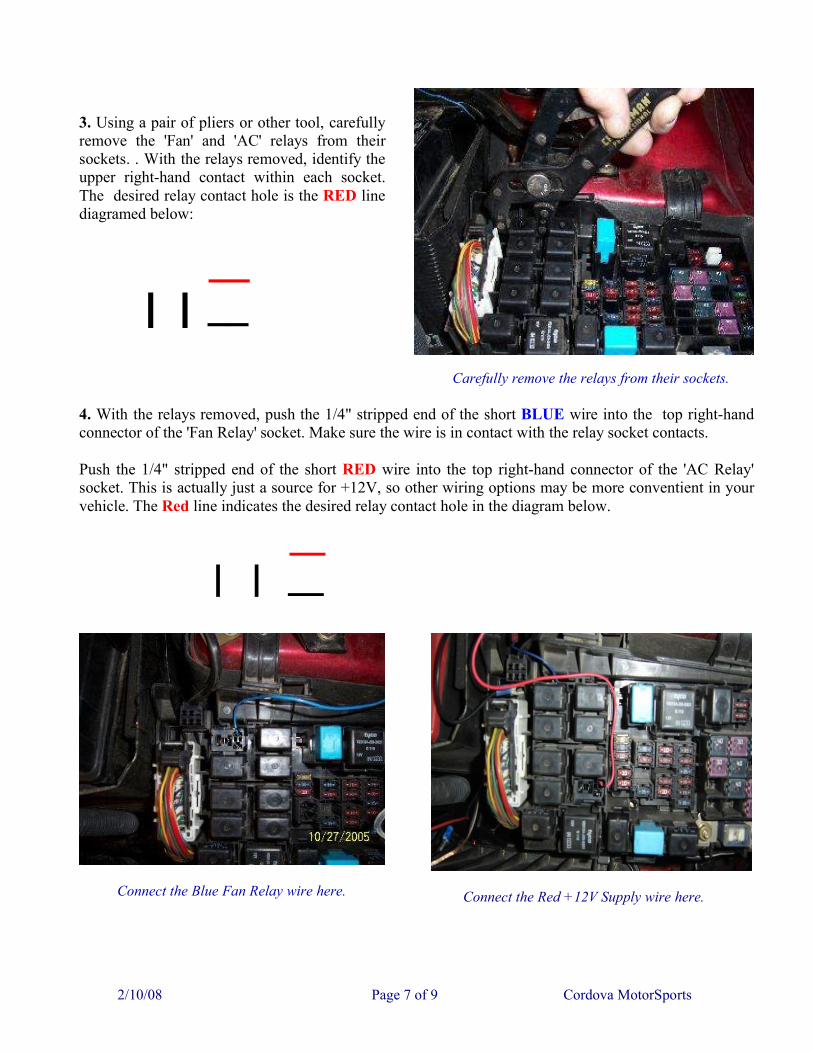
3. Using a pair of pliers or other tool, carefullyremove the 'Fan' and 'AC' relays from theirsockets. . With the relays removed, identify theupper right-hand contact within each socket.The desired relay contact hole is the RED linediagramed below:
__
| | __
Carefully remove the relays from their sockets.
4. With the relays removed, push the 1/4" stripped end of the short BLUE wire into the top right-handconnector of the 'Fan Relay' socket. Make sure the wire is in contact with the relay socket contacts.
Push the 1/4" stripped end of the short RED wire into the top right-hand connector of the 'AC Relay'socket. This is actually just a source for +12V, so other wiring options may be more conventient in yourvehicle. The Red line indicates the desired relay contact hole in the diagram below.
__ | | __
Connect the Blue Fan Relay wire here.
Connect the Red +12V Supply wire here.
2/10/08 Page 7 of 9 Cordova MotorSports

5. Push the relays back into their sockets tosecure the wires in the socket contacts. Routethe wires out of the upper left corner of thefuse panel.
Relays replaced and wires routed to back left corner.
6. Mount the Adjustable Fan Controller usingthe right hold-down bolt for the fuse box.Remove the stock bolt and replace it using theprovided 10mm bolt and two washers. Usingthe black washer on the bottom, and the silverwasher on top, re-install the bolt through themouning bracket and back into the fuse boxhold-down. Loosen the chassis ground boltlocated beneath the battery hold down bracketand slide the yellow lug connector under theground bolt. Retighten the ground, and fuse boxhold-down bolts.
Connect the ground connector to the chassis ground tab.
2/10/08 Page 8 of 9 Cordova MotorSports

7. Connect the red wire of the controller to thered +12V supply lead previously attached to therelay panel. Atttach the controllers black wireto the blue wire attached to Fan Relay. Attachthe white connector to the previously installedCoolant or Block thermal sensor.
Connect the power and fan control leads.
8. Replace the relay panel cover and tuck theloose wires down in the space between thebattery and relay panel. Using a smallscrewdriver, rotate the fan turn-on adjustmentto the full clockwise (coolest) setting. Start theengine and let it run for 5-10 minutes with theAC off. When the engine reaches roughly 120Fthe Red LED should illuminate and the radiatorfan should operate. Turning the adjustmentcounter-clockwise will turn the LED and fanoff until the engine temperature rises to the newsetting. A setting that supports fan on-offcycling should be possible using the coolantthermal sensor.
Testing the fully installed Controller
2/10/08 Page 9 of 9 Cordova MotorSports