adl300 - taylor liftstaylorlifts.co.uk/documents/adl300-syn-fprev0.603052016.pdf · information...
TRANSCRIPT

.... Functions description and parameters list
SIEI
Driv
eVector inverter for lifts with synchronous motors
ADL300

2 ADL300 • Functions description and parameters list
Information about this manual
This manual explains the functions and the description of the parameters.The informations about mechanical installation, electrical connection and fast start-up can be found on the ADL300 Quick start guide. The whole set of manuals can be found on the CD provided with the dirve.
Software versionThis manual is updated according the software version V V 4.0.0 .Variation of the number replacing “X” have no influence on the functionality of thedevice.The identification number of the software version is indicated on the identification plate of the drive or can be checked with the PAR 490 Firmware ver.rel parameter, menu 2.7.
General information
Note ! In industry, the terms “Inverter”, “Regulator” and “Drive” are sometimes interchanged. In this document, the term “Drive” will be used.
Before using the product, read the safety instruction section carefully. Keep the manual in a safe place and available to engineering and installation personnel during the product functioning period.Gefran S.p.A has the right to modify products, data and dimensions without notice. The data can only be used for the prod-uct description and they can not be understood as legally stated properties.
Thank you for choosing this Gefran product.We will be glad to receive any possible information which could help us improvingthis manual. The e-mail address is the following: [email protected] rights reserved.
ADL300 • Functions description and parameters list 3
Table of Contents
Information about this manual ..................................................................................................................2Symbols used in the manual...................................................................................................................................4
A - Programming ........................................................................................................................................5A.1 Asynchronous/Synchronous selection..............................................................................................................5A.2 Menu display modes ........................................................................................................................................5A.3 Programming of “function block” analog and digital input signals ....................................................................5A.4 Variable interconnections mode .......................................................................................................................5
B - Parameters and functions description (Expert list) ..........................................................................7Legend ....................................................................................................................................................................71 - MONITOR ........................................................................................................................................................82 - DRIVE INFO ...................................................................................................................................................103 - STARTUP WIZARD .......................................................................................................................................134 - DRIVE CONFIG .............................................................................................................................................145 - LIFT .................................................................................................................................................................18
5.1 – SPEED ........................................................................................................................................................................185.2 – RAMPS ........................................................................................................................................................................205.3 – LIFT SEQUENCES ......................................................................................................................................................225.4 – MECHANICAL DATA ..................................................................................................................................................275.5 – DISTANCE ...................................................................................................................................................................295.6 – EMERGENCY MODE .................................................................................................................................................355.7 – INPUT/OUTPUT .........................................................................................................................................................375.8 –PRE - TORQUE ...........................................................................................................................................................485.9 – LIFT ALARMS ..............................................................................................................................................................50
6 - .........................................................................................................................................................................537 - ..........................................................................................................................................................................538 - .......................................................................................................................................................................539 - ..........................................................................................................................................................................5310 - DIGITAL INPUTS ........................................................................................................................................5411 - DIGITAL OUTPUTS .....................................................................................................................................5512 - ANALOG INPUTS ..........................................................................................................................................5613 - ANALOG OUTPUTS ......................................................................................................................................5914 - MOTOR DATA ..............................................................................................................................................6115 - ENCODER CONFIG ......................................................................................................................................6416 - SPEED REG GAINS ....................................................................................................................................6917 - REGULATOR PARAM ................................................................................................................................7318 - TORQUE CONFIG .....................................................................................................................................7419 - FUNCTIONS ................................................................................................................................................76
19.1 - FUNCTIONS/INERTIA COMP ....................................................................................................................................7619.2 - FUNCTIONS/MOTOR OVERLOAD .........................................................................................................................7619.3 - FUNCTIONS/BRES OVERLOAD ............................................................................................................................7819.4 - FUNCTIONS/DOUBLE PAR SET...............................................................................................................................7919.5 - FUNCTIONS/COMPARE ..........................................................................................................................................8119.6 - FUNCTIONS/PADS ...................................................................................................................................................8219.7 - FUNCTIONS/DIRECTION COUNT ............................................................................................................................83
20 - COMMUNICATION ......................................................................................................................................8620.1 - COMMUNICATION/RS232 ........................................................................................................................................8620.2 - COMMUNICATION/FIELDBUS CONFIG .................................................................................................................8720.3 - COMMUNICATION/FIELDBUS M2S .......................................................................................................................8820.4 - COMMUNICATION/FIELDBUS S2M ......................................................................................................................9120.5 - COMMUNICATION/WORD COMP ..........................................................................................................................9320.6 - COMMUNICATION/WORD COMP ..........................................................................................................................94
21 - ALARM CONFIG ...........................................................................................................................................9523 - ALARM LOG ..............................................................................................................................................104PARAMETERS ON SELECTION LISTS, BUT NOT DISPLAYED ON KEYPAD ...............................................105
C - SELECTION LISTS ............................................................................................................................109L_ANOUT .........................................................................................................................................................109L_CMP ..............................................................................................................................................................109L_DIGSEL1 .......................................................................................................................................................109L_DIGSEL2 .......................................................................................................................................................110L_DIGSEL3 .......................................................................................................................................................110L_FBS2M ..........................................................................................................................................................110L_LIM ................................................................................................................................................................ 111L_MLTREF ........................................................................................................................................................ 111L_REF ............................................................................................................................................................... 111L_SCOPE ......................................................................................................................................................... 111L_VREF ............................................................................................................................................................ 111L_WDECOMP ................................................................................................................................................... 111

4 ADL300 • Functions description and parameters list
Symbols used in the manual
Indicates a procedure, condition, or statement that, if not strictly observed, could result in personal injury or death.Indique le mode d’utilisation, la procédure et la condition d’exploitation. Si ces consignes ne sont passtrictement respec-tées, il y a des risques de blessures corporelles ou de mort.
Indicates a procedure, condition, or statement that, if not strictly observed, could result in damage to or destruction of equipment.Indique et le mode d’utilisation, la procédure et la condition d’exploitation. Si ces consignes ne sont pas strictement res-pectées, il y a des risques de détérioration ou de destruction des appareils.
Indicates that the presence of electrostatic discharge could damage the appliance. When handling the boards, always wear a grounded bracelet.Indique que la présence de décharges électrostatiques est susceptible d’endommager l’appareil. Toujours porter un brace-let de mise à la terre lors de la manipulation des cartes.
Indicates a procedure, condition, or statement that should be strictly followed in order to optimize these applications.Indique le mode d’utilisation, la procédure et la condition d’exploitation. Ces consignes doivent êtrerigoureusement respec-tées pour optimiser ces applications.
Note ! Indicates an essential or important procedure, condition, or statement.
Indique un mode d’utilisation, de procédure et de condition d’exploitation essentiels ou importants.
Warning
Caution
Attention
D - Block Diagrams ................................................................................................................................113System diagram index (Syn. ).............................................................................................................................113Drive overview (DrvOverview) ............................................................................................................................113ADL1 application index (ADL1FuncIndex) ..........................................................................................................114Expansion card digital inputs (DigImpExp) .........................................................................................................117Expansion card digital outputs (DigOutExp) .......................................................................................................118Analog input (AnInpExp) .....................................................................................................................................119Analog output (AnOut) ........................................................................................................................................120Encoder config ....................................................................................................................................................121Functions ............................................................................................................................................................122Torque control (TorqueCtrl) .................................................................................................................................124Gains adaptive (GainAdapt) ...............................................................................................................................124
Appendix - 1.0 CANopen interface .......................................................................................................1261.1 CANopen functions .......................................................................................................................................1261.2 CANopen management ................................................................................................................................1291.3 Process Data Channel Control .....................................................................................................................1301.4 SDO management ........................................................................................................................................1311.5 Alarms ...........................................................................................................................................................1331.6 Configuration example ..................................................................................................................................134
Appendix - 2.0 Configuring the Drive to manage Peripheral Encoders ...........................................141

ADL300 • Functions description and parameters list 5
A - Programming
A.1 Asynchronous/Synchronous selection
The ADL300 is factory-set to operate in asynchronous motor control mode. To switch to the synchronous motor control mode, set PAR 6100 Load synch control (Menu 4 - DRIVE CONFIG). For information on switching control mode via keypad, reference should be made to the ADL300 Quick Start Guide (via inte-grated keypad, see paragraph 8.2.9; via optional keypad, see paragraph 8.3.15).
Note! If asynchronous motor control is selected, use the ADL300 Description of functions and list of parameters – Vector inverter for lifts with asyn-chronous motors manual
A.2 Menu display modes
The programming menu can be displayed in two modes, which can be selected using the Access mode parameter (04 - DRIVE CONFIG menu): • Easy (default) only the main parameters are displayed.• Expert all the parameters are displayed.
A.3 Programming of “function block” analog and digital input signals
The signals, variables and parameters of each single “function block” of the drive are interconnected in order to achieve the configurations and controls inside the control system.These can be managed and modified using the keypad, PC configurator or fieldbus programming.The programming mode is based on the following logic:
Src (source; i.e.: Ramp ref 1 src, PAR: 610) This term defines the source of the function block input, i.e. the signal to be processed in the function
block. The different configurations are defined in the relative selection lists.
Mon (display; i.e.: Ramp ref 1 mon, PAR: 620) This term refers to the variable output from the function block, which is the result of the calculations
performed on the actual block.
Input selected Variable
src Monitor
Function block
Parameter
Parameter
A.4 Variable interconnections mode
The source (src) allows the desired control signal to be assigned to the function block input. This operation is performed by using specific selection lists.
Possible control signal sources:1 – Physical terminalThe analog and digital signals come from the terminal strip of the regulation card and/or from those of the expansion cards.

6 ADL300 • Functions description and parameters list
2 – Drive internal variablesInternal drive control system variables, from “function block” calculations, sent via keypad, PC configurator or fieldbus.
Practical example The following examples illustrate the philosophies and methods with which more or less complex operations are performed in the single “function blocks”, the results of which represent the output of the block.
• Example: Changing the Speed Reference sourceThe main drive reference (in the default configuration) Ramp ref 1 mon (PAR: 620) is generated by the output of the func-tion block “Ramp setpoint Block”.
Its default source is the Analog input 1 mon signal (PAR: 1500), from the output of the function block “Analog input 1 Block”, which in this case refers to analog input 1 of the signal terminal strip.
To change the reference source from the analog input to a digital reference inside the drive, the input signal must be changed to “Ramp setpoint Block”. Enter the Ramp ref 1 src parameter (PAR: 610) and set a new reference, selecting it from among those listed in the L_ML-TREF selection list, for example Dig ramp ref 1 (PAR: 600).
• Example: Inverting the analog reference signalTo invert the “Analog input 1X Block” output signal, the value of the An inp 1X sign src parameter (PAR: 1626), which has a default setting of Null (no operation), must be changed by selecting the source of the command signal from among those listed in the L_DIGSEL 2 selection list, for example Digital input X mon, One (function always enabled), etc.
+1
-1
* -1
* +1
Null
Null
An inp 1X sign src
Analog input 1X monAnalog input 1X Block
Ramp Setpoint Block
Terminal input
Ramp ref 1 monRamp ref 1 src
Ramp ref invert src
The diagrams above illustrate the internal processing philosophy of the single “function blocks” and the result of these changes on the other interconnected “function blocks”.
Note ! This section contains a brief description of the functions of the other parameters in the function blocks not included for the changes in the example.
The Ramp ref invert src parameter (PAR: 616) can be used to select the source for the command to reverse the “Ramp setpoint” function block output.The output signal from the “Ramp setpoint” block is displayed in the Ramp ref 1 mon parameter (PAR: 620).

ADL300 • Functions description and parameters list 7
B - Parameters and functions description (Expert list)
Legend
Menu PAR Description UM Type FB BIT Def Min Max Acc Mod
1 - MONITOR 1.1 250 Output current A FLOAT 16/32 0.0 0.0 0.0 R F__
1.2 252 Output voltage V FLOAT 16/32 0.0 0.0 0.0 R F__
21.5 - COMMUNICATION/WORD COMP 21.5.1 4400 Word bit0 src LINK 16BIT 6000 0 16384 ERW F__
21.5.16 4430 Word bit15 src LINK 16BIT 6000 0 16384 ERW F__
L_DIGSEL1 ( Selection List ) [*]
( Level 1 menu)
( Level 2 menu )
Indexing of the menu and parameter
Parameter identifier
Parameter description
UM: unit of measure
Type of parameter
BIT Boolean, from modbus seen as 16 bitsENUM Selection list, from modbus seen as 16 bitsFLOAT Real, from modbus seen as 32 bitsINT16 Integer with sign 16 bits, from modbus seen as 16 bitsINT32 Integer with sign 32 bits, from modbus seen as 32 bitsILINK Selection list, from modbus seen as 16 bitsLINK Selection list, from modbus seen as 16 bitsUINT16 Integer without sign 16 bits, from modbus seen as 16 bitsUINT32 Integer without sign 32 bits, from modbus seen as 32 bits
Format of data exchanged on Fieldbus (16BIT, 32BIT)
Default value CALCF Value calculated as a number with floating point
CALCI Value calculated as a whole number
SIZE Value depending on the size of the drive
Minimum value
Maximum value
Accessibility :
E ExpertR ReadS Size (set value depending on the size of the device)W Write (scrittura)Z parameters that can be modified ONLY with the drive disabled
Available in regulation mode:
V = V/f Control (open loop) / PM synchronous S = Vect Flux OLF = Vect Flux CL (closed loop)
[*]
Selection lists:The “Sorgente.../Sorg...” format parameters are linked to a selection list. The source of the signal that will control the parameter can be selected from the list indicated.The lists are indicated in paragraph C of this manual.

8 ADL300 • Functions description and parameters list
1 - MONITOR Menu PAR Description UM Type FB BIT Def Min Max Acc Mod
1.1 250 Output current A FLOAT 16/32BIT 0.0 0.0 0.0 R F__
The drive output current is displayed.
Menu PAR Description UM Type FB BIT Def Min Max Acc Mod
1.2 252 Output voltage V FLOAT 16/32BIT 0.0 0.0 0.0 R F__
The drive line voltage output is displayed.
Menu PAR Description UM Type FB BIT Def Min Max Acc Mod
1.3 254 Output frequency Hz FLOAT 16/32BIT 0.0 0.0 0.0 R F__
The drive output frequency is displayed.
Menu PAR Description UM Type FB BIT Def Min Max Acc Mod
1.4 628 Ramp setpoint rpm INT16 16/32BIT 0 0 0 R F__
The ramp reference is displayed. This is the speed value the drive must reach at the end of the ramp.
Menu PAR Description UM Type FB BIT Def Min Max Acc Mod
1.5 664 Speed setpoint rpm INT16 16/32BIT 0 0 0 R F__
The speed reference is displayed. This is the value measured at the output of the speed reference circuit.
Menu PAR Description UM Type FB BIT Def Min Max Acc Mod
1.6 260 Motor speed rpm INT16 16/32BIT 0 0 0 R F__
The actual output speed of the motor is displayed (in FOC = speed measured by the encoder, in SLS/VF = speed esti-mated by the drive).
Menu PAR Description UM Type FB BIT Def Min Max Acc Mod
1.7 270 DC link voltage V FLOAT 16/32BIT 0.0 0.0 0.0 ER F__
The direct voltage of the intermediate circuit capacitors is displayed (DC-Bus).
Menu PAR Description UM Type FB BIT Def Min Max Acc Mod
1.8 272 Heatsink temperature °C INT16 16BIT 0 0 0 ER F__
The temperature measured on the drive heatsink is displayed.
Menu PAR Description UM Type FB BIT Def Min Max Acc Mod
1.9 280 Torque current ref A FLOAT 16/32BIT 0.0 0.0 0.0 ER F__
The current reference used for torque control is displayed (in the sensorless vector and field-oriented vector modes).
Menu PAR Description UM Type FB BIT Def Min Max Acc Mod
1.10 282 Magnet current ref A FLOAT 16/32BIT 0.0 0.0 0.0 ER F__
The magnetizing current reference is displayed (in the sensorless vector and field-oriented vector modes).
Menu PAR Description UM Type FB BIT Def Min Max Acc Mod
1.11 284 Torque current A FLOAT 16/32BIT 0.0 0.0 0.0 ER F__
The actual torque current value is displayed.
Menu PAR Description UM Type FB BIT Def Min Max Acc Mod
1.12 286 Magnet current A FLOAT 16/32BIT 0.0 0.0 0.0 ER F__
The actual magnetizing current value is displayed.

ADL300 • Functions description and parameters list 9
Menu PAR Description UM Type FB BIT Def Min Max Acc Mod
1.13 3212 Motor overload accum UINT16 16/32BIT 0 0 100 ER F__
The motor overload level is displayed (100% = alarm threshold).
Menu PAR Description UM Type FB BIT Def Min Max Acc Mod
1.14 368 Drive overload accum UINT16 16/32BIT 0 0 100 ER F__
The drive overload level is displayed. An instantaneous overload of 200% of the drive rated current is allowed for 10s. The thermal image I²t adjusts the drive output current thresholds. During normal operation, the instantaneous output current value can reach 200% of the drive rated current. When the overload level par. 368 Drive overload accum reaches 100%, the output current threshold is reduced to 100% of the rated current, and stays at that value until the I²t integrator cycle is complete. At this point the instantaneous overload of 200% or 150% (below 3Hz) will be re-activated.
Menu PAR Description UM Type FB BIT Def Min Max Acc Mod
1.15 3260 Bres overload accum UINT16 16/32BIT 0 0 100 ER F__
The braking resistor overload limit is displayed (100% = alarm threshold).
Menu PAR Description UM Type FB BIT Def Min Max Acc Mod
1.16 1066 Enable state mon BIT 16BIT 0 0 1 R F__
The drive Enable command status is displayed. Voltage must be present on terminal 7. The FR Forwardstart command is needed to start the inverter.
1 Enabled drive enabled0 Disabled drive disabled
Menu PAR Description UM Type FB BIT Def Min Max Acc Mod
1.17 1068 Start state mon BIT 16BIT 0 0 1 R F__
The drive Start command status is displayed.
Menu PAR Description UM Type FB BIT Def Min Max Acc Mod
1.18 1070 FastStop state mon BIT 16BIT 0 0 1 R F__
The drive FastStop command status is displayed.
Menu PAR Description UM Type FB BIT Def Min Max Acc Mod
1.19 1200 Digital input X mon UINT16 16BIT 0 0 0 R F__
The status of the digital inputs of the expansion card is displayed. It can also be read via a serial line or fieldbus. The data are contained in a word, where each bit is 1 if voltage is supplied to the corresponding input terminal.
1 Input enabled.0 Input disabled.
Example: 0 0 0 0 0 0 0 0 0 0 1 1
Enable DI 1
Menu PAR Description UM Type FB BIT Def Min Max Acc Mod
1.20 1400 Digital output X mon UINT16 0 0 0 R F__
The status of the digital outputs of the expansion card is displayed. It can also be read via a serial line or fieldbus. The data are contained in a word, where each bit is 1 if voltage is supplied to the corresponding input terminal.
1 Output enabled.0 Output disabled.
Example: 0 0 0 0 0 0 0 0 0 0 1 1
DO 1 DO 2
10 ADL300 • Functions description and parameters list
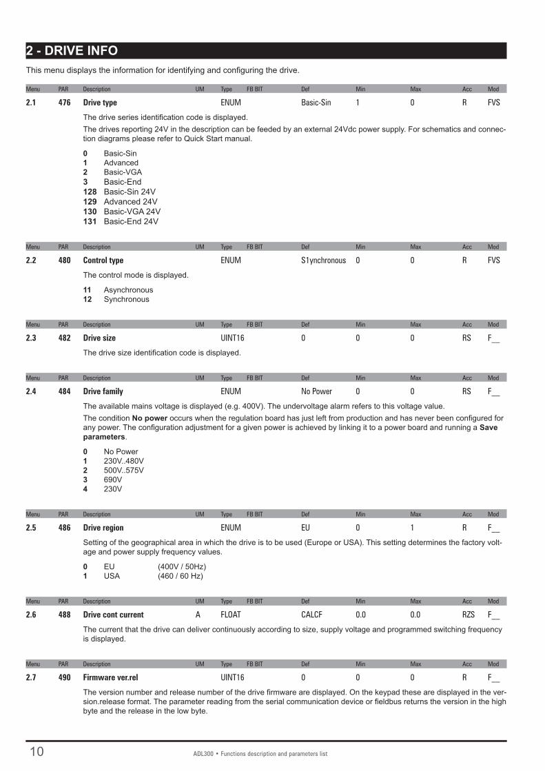
2 - DRIVE INFO This menu displays the information for identifying and configuring the drive.
Menu PAR Description UM Type FB BIT Def Min Max Acc Mod
2.1 476 Drive type ENUM Basic-Sin 1 0 R FVS
The drive series identification code is displayed. The drives reporting 24V in the description can be feeded by an external 24Vdc power supply. For schematics and connec-tion diagrams please refer to Quick Start manual.
0 Basic-Sin1 Advanced2 Basic-VGA3 Basic-End 128 Basic-Sin 24V 129 Advanced 24V 130 Basic-VGA 24V 131 Basic-End 24V
Menu PAR Description UM Type FB BIT Def Min Max Acc Mod
2.2 480 Control type ENUM S1ynchronous 0 0 R FVS
The control mode is displayed.
11 Asynchronous12 Synchronous
Menu PAR Description UM Type FB BIT Def Min Max Acc Mod
2.3 482 Drive size UINT16 0 0 0 RS F__
The drive size identification code is displayed.
Menu PAR Description UM Type FB BIT Def Min Max Acc Mod
2.4 484 Drive family ENUM No Power 0 0 RS F__
The available mains voltage is displayed (e.g. 400V). The undervoltage alarm refers to this voltage value.The condition No power occurs when the regulation board has just left from production and has never been configured for any power. The configuration adjustment for a given power is achieved by linking it to a power board and running a Save parameters.
0 No Power 1 230V..480V 2 500V..575V3 690V4 230V
Menu PAR Description UM Type FB BIT Def Min Max Acc Mod
2.5 486 Drive region ENUM EU 0 1 R F__
Setting of the geographical area in which the drive is to be used (Europe or USA). This setting determines the factory volt-age and power supply frequency values.
0 EU (400V / 50Hz)1 USA (460 / 60 Hz)
Menu PAR Description UM Type FB BIT Def Min Max Acc Mod
2.6 488 Drive cont current A FLOAT CALCF 0.0 0.0 RZS F__
The current that the drive can deliver continuously according to size, supply voltage and programmed switching frequency is displayed.
Menu PAR Description UM Type FB BIT Def Min Max Acc Mod
2.7 490 Firmware ver.rel UINT16 0 0 0 R F__
The version number and release number of the drive firmware are displayed. On the keypad these are displayed in the ver-sion.release format. The parameter reading from the serial communication device or fieldbus returns the version in the high byte and the release in the low byte.

ADL300 • Functions description and parameters list 11
Menu PAR Description UM Type FB BIT Def Min Max Acc Mod
2.8 496 Firmware type UINT16 0 0 0 R F__
Identifies the version of the special firmware installed in the drive
Menu PAR Description UM Type FB BIT Def Min Max Acc Mod
2.9 504 Application ver.rel UINT16 0 0 0 ER F__
The version and release number of the application used in the drive are displayed. On the keypad these are displayed in version.release format. When the parameter is read via serial line or fieldbus the version is returned in the high byte and the release in the low byte.
Menu PAR Description UM Type FB BIT Def Min Max Acc Mod
2.10 506 Application type UINT16 0 0 0 ER F__
The type of application currently used by the drive is displayed.
6 EFC (Creep to Floor) 10 EPC (Direct Approach)11 DCP3/DCP421 DS417 (CANOpen Lift CiA 417)
Menu PAR Description UM Type FB BIT Def Min Max Acc Mod
2.11 508 Application subver UINT16 0 0 0 ER FVS
The sub-version of the application displayed by parameter 506 is reported.
Menu PAR Description UM Type FB BIT Def Min Max Acc Mod
2.12 510 Time drive power on h.min UINT32 0 0.0 0.0 ER F__
The total time for which the drive has been powered is displayed.
Menu PAR Description UM Type FB BIT Def Min Max Acc Mod
2.13 512 Time drive enable h.min UINT32 0 0.0 0.0 ER F__
The time for which the enable hardware contact on the drive has been connected is displayed.
Menu PAR Description UM Type FB BIT Def Min Max Acc Mod
2.14 514 Number power up UINT16 0 0 0 ER F__
The number of times the drive has been powered on is displayed.
Menu PAR Description UM Type FB BIT Def Min Max Acc Mod
2.15 516 Time fan on h.min UINT32 0 0.0 0.0 ER F__
The total time for which the drive fan has been running is displayed.
Menu PAR Description UM Type FB BIT Def Min Max Acc Mod
2.16 520 Product S/N UINT32 0 0 0 R F__
The drive serial number is displayed.
Menu PAR Description UM Type FB BIT Def Min Max Acc Mod
2.17 522 Regulation S/N UINT32 0 0 0 R F__
The drive regulation card serial number is displayed.
Menu PAR Description UM Type FB BIT Def Min Max Acc Mod
2.18 524 Power S/N UINT32 0 0 0 R F__
The drive power card serial number is displayed.
Menu PAR Description UM Type FB BIT Def Min Max Acc Mod
2.19 526 Power file ver.rel UINT16 0 0 0 ER F__
The drive power card configuration release is displayed.

12 ADL300 • Functions description and parameters list
Menu PAR Description UM Type FB BIT Def Min Max Acc Mod
2.20 530 Slot 1 card type ENUM None 0 0 R F__
2.21 532 Slot 2 card type ENUM None 0 0 R F__
2.22 534 Slot 3 card type ENUM None 0 0 R F__
The type of expansion card installed in the relative slot of the drive is displayed.
0 None 257 I/O 1 1281 I/O 2 2305 I/O 3 3841 I/O 4 4865 I/O 5 5377 I/O 6 8 Enc 1 264 Enc 2 520 Enc 3 776 Enc 4 1032 Enc 5 4 Can/Dnet260 Profibus 516 Gdnet255 Unknown1544 Enc 4 Dbss
Note! See Appendix to the Quick start guide for further information on the expansion cards.
SLOT 3 indicates the presence of the CAN on the regulation card in versions ADL300-...-C
Menu PAR Description UM Type FB BIT Def Min Max Acc Mod
2.23 536 Slot 1 card S/N UINT32 0 0 0 R F__
2.24 538 Slot 2 card S/N UINT32 0 0 0 R F__
2.25 540 Slot 3 card S/N UINT32 0 0 0 R F__
The serial number of the expansion card installed in the relative slot of the drive is displayed.
Menu PAR Description UM Type FB BIT Def Min Max Acc Mod
2.26 546 Fw encoder ver.rel UINT16 0 0 0 R F__
The version and release number of the encoder firmware used in the drive are displayed. On the keypad these are dis-played in version.release format. When the parameter is read via serial line or fieldbus the version is returned in the high byte and the release in the low byte.
Menu PAR Description UM Type FB BIT Def Min Max Acc Mod
2.27 548 Fw encoder type UINT16 0 0 0 R F__
The type of firmware installed in the encoder is displayed.

ADL300 • Functions description and parameters list 13
3 - STARTUP WIZARD The startup wizard menu suggests a procedure for commissioning the drive quickly with a reduced number of settings. Advanced customization requires the use of the single parameters relating to the specific performance levels. Refer to the procedure de-scribed in chapter 9 Commissioning via keypad in the Quick start-up guide.

14 ADL300 • Functions description and parameters list
4 - DRIVE CONFIG Menu PAR Description UM Type FB BIT Def Min Max Acc Mod
4.1 550 Save parameters BIT 0 0 1 RW F__
Any changes to parameter values immediately affect drive operations, but are not automatically saved in the permanent memory.The “Save Parameters” command is used to save current parameter values in the permanent memory.Any changes that are not saved will be lost when the drive is switched off.To save parameters follow the procedure described in STEP 9 of the Startup wizard.
Menu PAR Description UM Type FB BIT Def Min Max Acc Mod
4.2 552 Regulation mode ENUM Flux vector CL 0 3 RWZ F__
The ADL300 is capable of operating with different control modes:2 Flux vector CL (Synchronous with permanent magnets)3 Autotune
In the field oriented vector mode (Flux vector CL/ Synchronous) an encoder is required for closed loop feedback. With this mode it is possible to achieve extremely high dynamic responses thanks to the regulation bandwidth, maximum torque even with the rotor blocked, speed and torque control. Numerous regulation parameters can be used to adjust the drive to each specific application, for instance adaptive gains, system inertia compensation, etc..
If the Startup wizard procedure is not used, self-tuning of the motor parameters is possible in the self-tuning mode (Autotune). This procedure must be used for both self-tuning with the engine standing still and with the motor turning.
Menu PAR Description UM Type FB BIT Def Min Max Acc Mod
4.3 554 Access mode ENUM Easy 0 1 RW F__
0 Easy 1 Expert The Easy mode gives access to a list of parameters that can be used for rapid drive commissioning. This type of configu-ration is suitable for the majority of applications.
Setting the parameter to Expert gives access to all the parameters in the firmware. This mode allows an extremely high level of customization to be achieved in order to exploit the potential of the ADL300 to the full.
On fw 4.0.0 the change from Easy to Expert can be protected by a dedicated password (PAR 566 Passwd expert). This function is available only via keypad and not via Gefran_eXpress.
Menù PAR Descripción UM Tipo FB BIT Def Min Max Acc Mod
4.4 566 Passwd expert UINT32 0 0 99999 RW FVS
EASY (default)
EXPERT
SERVICE
PAR 554=1
CHECK PSWD
SET PSWDS
PAR 554
0 Easy1 Expert
Access Mode
PAR 586
XXXX
Default = 0 (No password)
Set psswd expert
PASSWORD SERVICE
XXXX
Switch OFFSwitch ON
Switch OFFSwitch ON
Switch OFFSwitch ON
Wro
ng
PAR 566
XXXX
Default = 0 (No password)
Password expert
PAR 566 = PAR 586
(1) (2)
(1) or (2) depending of last saving
Type the password to enable parameter 554 Access mode. The password must have been entered via parameter 586 Set passwd expert.

ADL300 • Functions description and parameters list 15
Menù PAR Descripción UM Tipo FB BIT Def Min Max Acc Mod
4.5 Reserved
Menu PAR Description UM Type FB BIT Def Min Max Acc Mod
4.6 558 Application select ENUM Application 1 0 2 ERWZ F__
Selection of which IEC 61131-3-compliant application to make operational.
0 None 1 Application 1 2 Application 2
The drive is supplied already incorporating a number of applications developed in the IEC 61331-3 environment. To use these, configure the desired application, run save parameter, switch the drive off and then on again. In the default configu-ration the drive starts with the EFC lift application (see menu 5 - LIFT for the description of this application).
Note! The Load Default command (par. 580) does not modify this parameter
Menu PAR Description UM Type FB BIT Def Min Max Acc Mod
4.7 560 Mains voltage V ENUM 400 V SIZE SIZE ERWZS F__
Setting of the available mains voltage value in Volts. Detection of the undervoltage alarm refers to this value.
0 200 V 1 230 V 2 380 V 3 400 V 4 415 V 5 440 V 6 460 V 7 480 V 8 575 V 9 690 V
Menu PAR Description UM Type FB BIT Def Min Max Acc Mod
4.8 448 Emergency UV V FLOAT CALCF 0.0 CALCF ERWZ FVS
This parameter enables for the undervoltage threshold to be configured on the DC link. This parameter prevents the drive from opening the brake in emergency conditions without a DC link being supplied correctly.
Menu PAR Description UM Type FB BIT Def Min Max Acc Mod
4.9 450 Undervoltage V FLOAT CALCF CALCF CALCF ERWZS FVS
Lets you change the Undervoltage value. Minimum and maximum default values depend on line voltage.
Menu PAR Description UM Type FB BIT Def Min Max Acc Mod
4.10 454 Chopper ON V FLOAT CALCF CALCF CALCF ERWZS FVS
Corresponding to the threshold of activation of the braking resistor. It is so possible to increase this value just below the Overvoltage threshold level (ADL300-...-4 = 802 Vdc, ADL300-...-2T = 396 Vdc, ADL300-...-2M = 396 Vdc).Parameter’s range are defined thru IPA 560 Mains voltage setting.
Note ! If Mains voltage is set at the maximum possible value, the activation threshold of the braking resistor can only assume the max value and can not be changed.
Menu PAR Description UM Type FB BIT Def Min Max Acc Mod
4.11 570 Password UINT32 0 0 99999 ERW F__
You can enter a password to protect the parameters from unauthorized tampering: the password can consist of a com-bination of a maximum of any 5 figures that can be selected by the user. All parameters are locked, except this one and Save parameters.Entering the password, press the E key, then enter the password and press the E key again to enable it (a password ena-bled message (Enabled) is displayed).So that the password remains valid even after switching the unit off and then switching it back on, save it using the Save parameters command.

16 ADL300 • Functions description and parameters list
When the password is enabled any attempts to modify a parameter are blocked and the Password enabled message is displayed.To disable the password, enter the Password parameter (570) in the DRIVE CONFIG menu. Check that the password is enabled (Enabled), press E and enter the combination of figures that make up the password.Press E again. A message is displayed telling you the password is no longer enabled (Disabled).To make sure the password continues to be disabled even after switching the unit off and then switching it back on, save this configuration using the Save parameters command.When an incorrect password is entered, the Password wrong message is displayed.
Menu PAR Description UM Type FB BIT Def Min Max Acc Mod
4.12 572 Application key UINT32 0 0 4294967295 ERW F__
This parameter can be used to enter the key for enabling the PLC application.You may need to enter a key to definitively enable some PLC applications. Please contact Gefran for details about which PLC applications require the key.If executing an application that envisages a key verification and the key is incorrect, enabling is forced for 200 hours (time drive enabled). In this phase a message is displayed informing you that the period of forced enabling time is about to expire.At the first power-on after the 200 hours an alarm is generated and the application does not start.Please contact Gefran for the numerical value of the key.
Menu PAR Description UM Type FB BIT Def Min Max Acc Mod
4.13 586 Set passwd expert UINT32 0 0 99999 ERW FVS
Enables the password to protect change of the setting of parameter 554 Access mode from Easy to Expert. A value other than 0 must be entered. Entering 0 disables the password. You have to enter Expert mode to access parameter 586 Set passwd expert. The password value must be entered twice to be accepted.After the password is set, parameter 554 Access mode remains in Expert mode; to enable the protection, enter the pass-word in parameter 566 Passwd expert. Now parameter 554 Access mode will go to Easy mode. At every power-on, the drive will start in Easy mode with the protection enabled.
Menu PAR Description UM Type FB BIT Def Min Max Acc Mod
4.14 574 Startup display INT16 -1 -1 20000 ERW F__
It is possible to set the parameter that will automatically be displayed when the drive is switched on.If set to -1 the main menu is automatically displayed when the drive is turned on.If set to 0 the display page is automatically displayed when the drive is turned on.
Menu PAR Description UM Type FB BIT Def Min Max Acc Mod
4.15 576 Display backlight BIT 0 0 1 ERW F__
Enabling of the backlight on the drive display. If set to 0 the display backlight will go off when the drive has been on for three minutes. If set to 1 the backlight will stay on for as long as the drive is powered.
Menu PAR Description UM Type FB BIT Def Min Max Acc Mod
4.16 578 Language select ENUM English 0 4 RWZ F__
Setting of the drive programming language.
0 English 1 Italian 2 French 3 German 4 Spanish 8 Turkish
Note! The Load Default command (par. 580) does not modify this parameter.

ADL300 • Functions description and parameters list 17
Menu PAR Description UM Type FB BIT Def Min Max Acc Mod
4.17 580 Load default BIT 0 0 1 RWZ F__
Transfers the standard factory settings to the drive memory (“Def” column in the parameters table).
Menu PAR Description UM Type FB BIT Def Min Max Acc Mod
4.18 590 Save par to keypad BIT 0 0 1 RW F__
Transfers the parameters currently stored in the drive and saves them in the keypad memory (See ADL300 Quick Start manual, chapter 8.3.13).
Menu PAR Description UM Type FB BIT Def Min Max Acc Mod
4.19 592 Load par from keypad BIT 0 0 1 RWZ F__
Transfers the parameters from the keypad memory to the drive (See ADL300 Quick Start manual, chapter 8.3.13).
Menu PAR Description UM Type FB BIT Def Min Max Acc Mod
4.20 594 Keypad memory select UINT16 1 1 5 ERW F__
Selection of the area of the keypad memory to which to transfer and save the parameters stored in the drive.
Menu PAR Description UM Type FB BIT Def Min Max Acc Mod
4.21 596 Save to SD card BIT 0 0 1 RW F__
Transfers the drive parameters to the SD memory card (See chapter 8.3.14 of the Quick start-up guide).
Menu PAR Description UM Type FB BIT Def Min Max Acc Mod
4.22 598 Load from SD card BIT 0 0 1 RWZ F__
Transfers the parameters from the SD memory card to the drive (See chapter 8.3.14 of the Quick start-up guide).
Menu PAR Description UM Type FB BIT Def Min Max Acc Mod
4.23 6100 Load asynch control BIT 0 0 1 ERW FVS
Select the Asynchronous motor control mode. The drive is reset and restarts in the new control mode.To perform this operation via keypad, see chapters 8.2.9 and 8.2.15 of the ADL 300 Quick Start Guide.
Note! Important: the default parameters including the LIFT application are reloaded.
This can only be done with the drive disabled.

18 ADL300 • Functions description and parameters list
5 - LIFT5.1 – SPEED
Menu PAR Description UM Type FB BIT Def Min Max Acc Mod
5.1.1 11002 Travel units sel m/s ENUM 0 0 2 RW F__
Selection of the unit of measure for speed references.
1 m/s (cabin speed and depends on the mechanical constant)2 Rpm (speed of the motor shaft)3 USCS (US units: fpm, ft/s2, ft/s3)
When the unit of measure is modified the conversion constants are re-calculated, the units of measure are changed in the parameter list and the multispeed values are converted into the new unit of measure (the result may contain approxima-tions due to the conversion calculations).A variable representing the speed of the cabin in m/s (fpm) is always available (PAR 12210). There are fixed units of measure for the acceleration and deceleration parameters m/s² (ft/s2), and for jerks m/s³ (ft/s3).
Menu PAR Description UM Type FB BIT Def Min Max Acc Mod
5.1.2 11020 Multi speed 0 m/s FLOAT 0.10 -10000 10000 RW F__
Setting of the multispeed 0 value. Can be selected via digital input, fieldbus, etc.The selected value is the reference for the S-shaped lift ramp.This setting is taken as the default low speed value.
Menu PAR Description UM Type FB BIT Def Min Max Acc Mod
5.1.3 11022 Multi speed 1 m/s FLOAT 1.00 -10000 10000 RW F__
Setting of the multispeed 1 value. Can be selected via digital input, fieldbus, etc.The selected value is the reference for the S-shaped lift ramp.This setting is taken as the default high speed value.
Menu PAR Description UM Type FB BIT Def Min Max Acc Mod
5.1.4 11024 Multi speed 2 m/s FLOAT 0.40 -10000 10000 RW F__
Setting of the multispeed 2 value. Can be selected via digital input, fieldbus, etc.The selected value is the reference for the S-shaped lift ramp.This setting is taken as the default maintenance speed value.
Menu PAR Description UM Type FB BIT Def Min Max Acc Mod
5.1.5 11026 Multi speed 3 m/s FLOAT 0.00 -10000 10000 RW F__
Setting of the multispeed 3 value. Can be selected via digital input, fieldbus, etc.The selected value is the reference for the S-shaped lift ramp.
Menu PAR Description UM Type FB BIT Def Min Max Acc Mod
5.1.6 11028 Multi speed 4 m/s FLOAT 0.00 -10000 10000 RW F__
Setting of the multispeed 4 value. Can be selected via digital input, fieldbus, etc.The selected value is the reference for the S-shaped lift ramp.
Menu PAR Description UM Type FB BIT Def Min Max Acc Mod
5.1.7 11030 Multi speed 5 m/s FLOAT 0.00 -10000 10000 RW F__
Setting of the multispeed 5 value. Can be selected via digital input, fieldbus, etc.The selected value is the reference for the S-shaped lift ramp.
Menu PAR Description UM Type FB BIT Def Min Max Acc Mod
5.1.8 11032 Multi speed 6 m/s FLOAT 0.00 -10000 10000 RW F__
Setting of the multispeed 6 value. Can be selected via digital input, fieldbus, etc.The selected value is the reference for the S-shaped lift ramp.

ADL300 • Functions description and parameters list 19
Menu PAR Description UM Type FB BIT Def Min Max Acc Mod
5.1.9 11034 Multi speed 7 m/s FLOAT 0.00 -10000 10000 RW F__
Setting of the multispeed 7 value. Can be selected via digital input, fieldbus, etc.The selected value is the reference for the S-shaped lift ramp.
Menu PAR Description UM Type FB BIT Def Min Max Acc Mod
5.1.10 12010 Actual multi spd sel ENUM R F__
The currently selected speed is displayed.
0 Multi speed 01 Multi speed 12 Multi speed 23 Multi speed 34 Multi speed 45 Multi speed 56 Multi speed 67 Multi speed 78 Null
Menu PAR Description UM Type FB BIT Def Min Max Acc Mod
5.1.11 12210 Actual speed ref m/s FLOAT R F__
The speed of the cabin is displayed in m/s.

20 ADL300 • Functions description and parameters list
5.2 – RAMPS
The lift application envisages an S-shaped ramp function with the possibility of setting 4 independent jerks and linear acceleration and deceleration factors, as in the standard profile illustrated in the figure below.
Acc ini jerk
Acceleration
Dec ini jerk
Deceleration
Dec end jerk
Stop deceleration
Speed ref 1
Slow Down dist
Acc end jerk
Spd 0 ref thr
The Acc ini Jerk, Acceleration and Acc end jerk values used to execute the acceleration ramp are calculated by multiplying the cor-responding parameters by the acceleration ramp factor (Percent acc factor), while the Dec ini jerk, Deceleration and Dec end jerk values used to execute the deceleration ramp are calculated by multiplying the corresponding parameters by the deceleration ramp factor (Percent dec factor, PAR 11056).
When the Start command is removed, the reference speed is zero regardless of the reference selected in the multispeeds. In this fi-nal part of the profile the jerk deceleration values are used directly (not multiplied by Percent dec factor, PAR 11056) with the Stop deceleration parameter as the linear deceleration. The factors for the final section of the profile are also used in case of a Stop lift emergency condition.
Menu PAR Description UM Type FB BIT Def Min Max Acc Mod
5.2.1 11040 Acc ini Jerk m/s³ FLOAT 0.50 0.01 20 RW F__
Setting of the jerk value for the first part of the acceleration.
Menu PAR Description UM Type FB BIT Def Min Max Acc Mod
5.2.2 11042 Acceleration m/s² FLOAT 0.60 0.01 10 RW F__
Setting of the maximum acceleration value.
Menu PAR Description UM Type FB BIT Def Min Max Acc Mod
5.2.3 11044 Acc end jerk m/s³ FLOAT 1.40 0.01 20 RW F__
Setting of the jerk value for the last part of the acceleration.Menu PAR Description UM Type FB BIT Def Min Max Acc Mod
5.2.4 11046 Dec ini jerk m/s³ FLOAT 1.40 0.01 20 RW F__
Setting of the jerk value for the first part of the deceleration.
Menu PAR Description UM Type FB BIT Def Min Max Acc Mod
5.2.5 11048 Deceleration m/s² FLOAT 0.60 0.01 10 RW F__
Setting of the maximum deceleration value.
Menu PAR Description UM Type FB BIT Def Min Max Acc Mod
5.2.6 11050 Dec end jerk m/s³ FLOAT 0.50 0.01 20 RW F__
Setting of the jerk value for the last part of the deceleration.
Menu PAR Description UM Type FB BIT Def Min Max Acc Mod
5.2.7 11052 Stop deceleration m/s² FLOAT 0.70 0.01 10 RW F__
Setting of the maximum deceleration value used when the start command is removed.
Menu PAR Description UM Type FB BIT Def Min Max Acc Mod
5.2.8 11054 Percent acc factor Perc FLOAT 100.00 10 10000 RW F__
Setting of the acceleration factor multiplier. If set to 100 the ramp uses the factors entered in the parameters.

ADL300 • Functions description and parameters list 21
If set to a value of less than 100 the lift will tend to accelerate over a longer distance.If set to a value of more than 100 the lift will tend to accelerate over a shorter distance.
Menu PAR Description UM Type FB BIT Def Min Max Acc Mod
5.2.9 11056 Percent dec factor Perc FLOAT 100.00 10 10000 RW F__
Setting of the deceleration factor multiplier. If set to 100 the ramp uses the factors entered in the parameters.If set to a value of less than 100 the lift will tend to decelerate over a longer distance.If set to a value of more than 100 the lift will tend to decelerate over a shorter distance.

22 ADL300 • Functions description and parameters list
5.3 – LIFT SEQUENCES
This menu shows the parameters used to manage and define the travel of the lift depending on the status of the inputs and alarms. The structure of the lift sequences is summarised below.
K4 delayK2M/K3M delay
Acc ini jerk
Acceleration
Dec ini jerk
Deceleration
Dec end jerk
End decel
Brake open delay
Ope
n co
ntac
.
Sta
rt F
w /
Rw
Clo
se c
onta
ct
Sta
rt m
agne
t.
Ope
n br
ake Running
Wai
t 0 r
ef
Clo
se b
rake
Run Cont Close delay
Spd 0 ref delay
Brake close dly
Start / Rev cmd
Mlt spd s 0
Mlt spd s 1
Mlt spd s 2
Speed ref 1
Magn. current
RUN cont
Lift enable
cmd mon
BRAKE cont mon
Lift Start mon
Lift Landing mon
Lift DC brake mon
Slow Down dist
PLC
TO
DR
IVE S
IGN
ALS
DR
IVE T
O P
LC
SIG
NA
LS
Acc end jerk
(Only FOC/BRS)
(Only V/F)
HW Enable
Spd 0 ref thr
SA
FETY
SIG
NA
LS
Contactorless OK
Contactorless
enable
K2M / K3M
K4
K4 delayK2M/K3M delay of the contactors
Run Cont open delay
Starting sequence:1 Reading of the enable hardware input and checking for alarms (enabling is aborted in case of an alarm)2 Detection of the Enable and Start commands as set in the Sequence start mode parameter3 When the Start forward/reverse command is received, a command is sent to close the contactors, depending on the
direction of travel4 When the time set in Cont close delay has elapsed the internal Enable lift signal is activated5 The system waits for the magnetisation signal from the drive (Drive ready)6 At the end of magnetisation the open brake signal is activated

ADL300 • Functions description and parameters list 23
7 The system waits for the brake to be opened (Brake open delay)8 When the delay before opening the brake has elapsed the Start lift command is sent and movement is enabled.
Sequence of movement:1 The motor is started and moves slowly at the speed set in Smooth start speed for the time indicated in Smooth start
delay2 At the end of Smooth start delay, movements are managed by the multispeeds and S-shaped ramp3 When the set speed is exceeded, the Brake 2 mon output signal can be used to check that the brake has actually been
opened4 The EFC function with space control can be used to change to a slower speed5 When the Start forward/reverse signal is lowered the signal indicating arrival at the floor is enabled and the start lift
signal is disabled6 The start command can be sent again until the drive reaches zero speed: the operating conditions are restored.
Stopping sequence:1 When zero speed is reached the DC stop command is enabled (SSC control)2 The application waits the time needed to reach zero speed and sends the command to close brakes 1 and 2 3 It waits the time necessary for the brakes to close (Brake close delay) and, if the current is to be reduced with a ramp, it
waits for the current limit to reach zero. The internal Enable lift, arrival zone and DC brake signals are then lowered.4 The application waits the time set in Contactor open delay and checks that the current supplied is zero, before sending
a command to open the contactors.
It is essential to make sure that whenever a drive alarm condition is generated or the drive is disabled, the drive is stopped and a command is sent to open the contactors.
Menu PAR Description UM Type FB BIT Def Min Max Acc Mod
5.3.1 11060 Sequence start mode ENUM 0 0 2 RW F__
Setting of the procedure to start the contactor command sequence.
0 Start forward/reverse1 Enable2 Multispeed != 0
If set to 0 the contactor sequences can be enabled without the Enable command (Enable is only required for motor opera-tion). The Enable signal can be sent by an auxiliary contact of the output contactors.If set to 1 the contactor sequences can only be enabled if the Enable command is active.If set to 2 the contactor sequences can be enabled using the multispeed values. Multispeed values other than 0 cause the sequence to start. The start command must also be enabled.
Menu PAR Description UM Type FB BIT Def Min Max Acc Mod
5.3.2 11062 Cont close delay ms INT32 200.00 0 10000 RW F__
Setting of the delay time for closing the contactor.
Menu PAR Description UM Type FB BIT Def Min Max Acc Mod
5.3.3 11064 Brake open delay ms INT32 200 0 10000 RW F__
Setting of the brake opening delay time.
Menu PAR Description UM Type FB BIT Def Min Max Acc Mod
5.3.4 11066 Smooth start delay ms INT32 0 0 10000 RW F__
Setting of the time for which the Smooth start speed speed is enabled. If this parameter is set to zero, the S-shaped profile is executed directly at the start, and the soft start function is excluded.
Menu PAR Description UM Type FB BIT Def Min Max Acc Mod
5.3.5 11068 Brake close delay ms INT32 500.00 0 10000 RW F__
Setting of the brake closing delay time.
Menu PAR Description UM Type FB BIT Def Min Max Acc Mod
5.3.6 11070 Current down delay ms INT32 200 0 10000 RW F__

24 ADL300 • Functions description and parameters list
Setting of the time necessary to lower the torque from the limit value enabled during travel to 0. It defines the inclination of the down ramp in the “Current down ramp” function. The purpose of this function is to prevent the immediate removal of motor torque when the brake is closed, which would cause mechanical strain in the cabin.To avoid this phenomenon when the brake is closed the current limits are brought to the current value in use and then lowered on the ramp.To enable the function the Current down delay parameter must be set to a value other than zero.This is only possible when Torque curr lim sel has a value other than “OFF”, otherwise Current down delay is forced to zero.
Menu PAR Description UM Type FB BIT Def Min Max Acc Mod
5.3.7 11072 Contactor open delay ms INT32 200.00 0 10000 RW F__
Setting of the contactor opening delay time.
Menu PAR Description UM Type FB BIT Def Min Max Acc Mod
5.3.8 11078 Speed 0 threshold rpm INT16 1.00 RW F__
Setting of the zero speed threshold, below which the zero speed signal is activated.
Menu PAR Description UM Type FB BIT Def Min Max Acc Mod
5.3.9 11080 Speed 0 delay ms UINT16 400.00 0 10000 RW F__
Setting of the zero speed delay. After the zero speed signal and after the time set in this parameter the zero speed signal is activated. These parameters are used to know the cabin stop.
Menu PAR Description UM Type FB BIT Def Min Max Acc Mod
5.3.10 11082 Smooth start speed Hz FLOAT 0.00 0.00 RW F__
Setting of the speed in the smooth start phase.
Menu PAR Description UM Type FB BIT Def Min Max Acc Mod
5.3.11 11084 Smooth start mode ENUM 2 1 2 RW F__
Setting of the soft start mode.
1 Speed consant2 Jerk variable
If set to 1 the soft speed is automatically selected after the start command regardless of the selected multispeed. The duration of the smooth speed depends on the Smooth start delay parameter: if this parameter is set to zero the selected multispeed is used and not the soft speed. This setting is used in systems with a reducer, as it helps to overcome initial friction before starting with the profile.If set to 2 an even slower starting mode is set, which uses the start jerk of the variable acceleration in the smooth start phase. Depending on the values set in Smooth start speed and Smooth start delay the jerk value is calculated at the end of the soft start phase with a linear ramp that changes this jerk from 0 to the calculated value.The use of a variable value jerk obtains a variable start acceleration that follows a parabolic trajectory, enabling extremely reduced variations in initial speed. This setting is mainly used in systems with gearless motors.
Speed ref
Smooth start dly
1
0
Lift start mon
Time
Smooth start spd
Menu PAR Description UM Type FB BIT Def Min Max Acc Mod
5.3.12 11086 Door open speed m/s FLOAT 0.00 RW F__

ADL300 • Functions description and parameters list 25
Setting of the door opening speed. Source to enable brake release through the digital input. In standard sequence brake release is controlledby the drive and therefore this parameter is set to ONE. In case that brake release should be conditionedby some external control (e.g. PLC), set this parameter to digital input controlled by PLC.Internal sequence for brake release will wait until this input is asserted.During run brake will be closed whenever this input becomes not asserted.
Door open src
Speed
Door open speed
Function enable signal
Menu PAR Description UM Type FB BIT Def Min Max Acc Mod
5.3.13 11088 Contactorless Enable BIT 0 0 1 RW FVS
This should be configured if the contactorless mode is desired. By enabling this parameter, the fast enable command is brought to digital Input 7 (if there is no short circuit on the motor phases, this parameter should be returned to the de-fault value) and the drive indicates the contactorless operation mode to the controller through digital output 4 (see Figure 7.3.2.8-A in the ADL300 QS installation manual).
Menu PAR Description UM Type FB BIT Def Min Max Acc Mod
5.3.14 11822 Em max speed UINT32 200 R/W FVS
Sets maximum car (or motor) speed during the maneuver. The speed can be expressed in m/s (for the car) or in rpm (for the motor).
Menu PAR Description UM Type FB BIT Def Min Max Acc Mod
5.3.15 11824 Brake lock time UINT32 4 1 30 R/W FVS
Sets brake lock time when the car reaches maximum allowed speed.
Menu PAR Description UM Type FB BIT Def Min Max Acc Mod
5.3.16 11826 Inspection Behaviour Enum None 0 2 R/Z FVS0 None1 Fast Stop2 ImmediateManages the stop ramp in maintenance/inspection mode. If enabled, the function allows greater deceleration compared to nominal deceleration. Three modes are available: None: function disabled (default). The car stops with the normal ramps inserted.Fast Stop: the 200 ms stop function is enabled if the set maintenance speed (PAR 11024 Multi speed 2 or PAR 11828
Inspection speed) is below 0.63 m/s. If the set speed is higher it is automatically limited to 0.63 m/s.Immediate: car stops immediately with brake close. The car stops immediately (with no ramp) when the button on the
maintenance button panel is released.
Menu PAR Description UM Type FB BIT Def Min Max Acc Mod
5.3.17 11828 Inspection speed Enum 2 R/Z FVS0 Multi speed 01 Multi speed 12 Multi speed 23 Multi speed 34 Multi speed 45 Multi speed 56 Multi speed 67 Multi speed 78 NullMaintenance speed.
Menu PAR Description UM Type FB BIT Def Min Max Acc Mod
5.3.18 12014 Trip number INT32 0 R F__
The lift journey counter is displayed. The counter increases each time the Start lift signal is activated.

26 ADL300 • Functions description and parameters list
Menu PAR Description UM Type FB BIT Def Min Max Acc Mod
5.3.19 12016 Sequence state UINT16 0 R F__
The lift sequence status is displayed. (see graph)

ADL300 • Functions description and parameters list 27
5.4 – MECHANICAL DATA
The parameters described in this menu are used to define the mechanical and physical features of the system. Mechanical constantsThe mechanical constant defines the ratio between motor rpm and distance travelled by the cabin.The ConstMech can be calculated in two ways, depending on which conversion method is used.
- Directly: Mechanical constant = System speed/(Full scale speed/60)- Mechanical data: Mechanical constant = (π *Pulley diameter)/Reduction gear ratio
PulleyMotor Gearbox
Pulley diameter
Rope weight
Car weight
Load weight
Counter weight
Gearbox ratio
The mechanical constant is calculated when the drive is turned on and re-calculated each time one of the parameters used to deter-mine this value is modified (Mechanical calc mode, Full scale speed, Contract speed, Pulley diameter, Gearbox ratio).The method used to calculate the mechanical constant can be selected regardless of the control mode (SSC, Flux vector OL, Flux vector CL, Synchronous) or the unit of measure to be used.
Weights and inertiaEntering the mechanical features of the system makes it possible to calculate the total inertia applied to the motor.After modifying these parameters the calculated inertia value is automatically saved in the “Inertia comp” parameter to enable cor-rect inertia compensation.The value of the inertia that can be entered in the “Inertia“ parameter in the “16 - SPEED REG GAINS” menu is displayed to calcu-late the speed loop parameters more accurately. This operation is performed automatically when PAR 11162 Calc spd reg gain is enabled.
Menu PAR Description UM Type FB BIT Def Min Max Acc Mod
5.4.1 11006 Contract speed m/s FLOAT 1 0 10 RW F__
Represents the speed of the system. It is also used to calculate the mechanical constant. The cabin speed in m/s is as-sociated with the full scale speed (par. 628) to obtain the conversion factor (m/rpm).
Menu PAR Description UM Type FB BIT Def Min Max Acc Mod
5.4.2 11008 Mechanical calc mode INT16 0 0 1 ERW F__
Setting of the method for calculating the unit of measure, depending on the speed of the cabin and of the motor (Direct method) or according to the mechanical ratios (Mechanical data method).
0 Direct method1 Mechanical data
Menu PAR Description UM Type FB BIT Def Min Max Acc Mod
5.4.3 11010 Gearbox ratio FLOAT 2 ERW F__
Setting of the ratio between the speed of the motor and of the pulley.

28 ADL300 • Functions description and parameters list
Menu PAR Description UM Type FB BIT Def Min Max Acc Mod
5.4.4 11012 Pulley diameter m FLOAT 0.32 ERW F__
Setting of the diameter of the pulley.
Menu PAR Description UM Type FB BIT Def Min Max Acc Mod
5.4.5 11150 Car weight kg FLOAT 0.00 RW F__
Setting of the weight of the cabin.
Menu PAR Description UM Type FB BIT Def Min Max Acc Mod
5.4.6 11152 Counter weight kg FLOAT 0.00 RW F__
Setting of the weight of the counterweight.
Menu PAR Description UM Type FB BIT Def Min Max Acc Mod
5.4.7 11154 Load weight kg FLOAT 0.00 RW F__
Setting of the weight of the maximum load for system dimensions.
Menu PAR Description UM Type FB BIT Def Min Max Acc Mod
5.4.8 11156 Rope weight kg FLOAT 0.00 RW F__
Setting of the weight of the cable.
Menu PAR Description UM Type FB BIT Def Min Max Acc Mod
5.4.9 11158 Gearbox inertia kgm² FLOAT 0.00 RW F__
Setting of the inertia of the mechanical reducer.
Menu PAR Description UM Type FB BIT Def Min Max Acc Mod
5.4.10 11160 Motor inertia kgm² FLOAT 0.00 RW F__
Setting of the motor inertia.
Menu PAR Description UM Type FB BIT Def Min Max Acc Mod
5.4.11 11162 Calc spd reg gains ENUM INT 0 0 1 RW F__
If enabled this writes the inertia value in parameter 2240 Inertia, calculates the gains of the speed loop, sets parameters 2200 to 2210 to 100% and writes the calculated values in parameters 2236 Speed reg P gain, 2238 Speed reg I time and 2242 Bandwidth. The value of the parameter is automatically reset to 0 once calculation starts.
Menu PAR Description UM Type FB BIT Def Min Max Acc Mod
5.4.13 12020 Inertia calculated kgm² FLOAT 0 R F__
The inertia of the system with half load applied to the motor is displayed. This value can be entered in the Inertia parameter in the “16 - SPEED REG GAINS” menu.
Menu PAR Description UM Type FB BIT Def Min Max Acc Mod
5.4.13 12022 SpeedLineCalc m/s FLOAT 0 R F__
The linear speed in m/s calculated using the 11010 Gearboxratio and 11012 Pulleydiam parameters is displayed.

ADL300 • Functions description and parameters list 29
5.5 – DISTANCEUse of the distances facilitates positioning of the deceleration sensors and is helpful for managing short floors.The aim of the function that considers distances is to start decelerating from high speed in order to reach the approach speed in proximity to the landing zone.Up to a maximum of 8 different slow down distances can be managed (real distance between the start of the sensor and the floor) associated with the different multispeeds. The distance to be used is selected after enabling the drive, before the cabin starts to move. Different distances cannot be selected while the cabin is travelling.If the slow down distance is shorter than the real deceleration distance for the selected target speed, the speed is automatically limited so that the stop is always correct. When this speed limiter is enabled a Speed target alarm (warning) is generated.
High Speed
d2d1
Speed Limit
Distance function: Speed limits
d1 = Speed limiter (Speed Limitd2 = High speed
If the slow down sensor is met during acceleration, the distance required to terminate the acceleration and deceleration phases may be greater than the distance available: in that case the last acceleration jerk is increased to enable correct landing.
d1
Acc end jerk
d1 Distancedisabled
Piano corto (Short Floor) Piano standard (Standard Floor)
Distance function: Short floor
..... Distance disabled__ Distance enabled (Short floor)__ Standard floor
Also note that when the position sensor is not enabled in the landing zone, its exact length is not known. To ensure correct decel-eration this distance is estimated on the basis of the value entered in the Landing zone dist parameter.When this is equal to zero the distance is calculated on the basis of the value of the low speed and deceleration parameters and shown in the Landing zone space parameter. The user should make sure this distance is approximately the real length of the land-ing zone.In FOC mode the distance is calculated by reading the encoder position.In the SSC and SLS modes the distance is estimated (SpdRef*Time) and is thus subject to errors due to the difference between the real speed of the motor and the speed reference.
Menu PAR Description UM Type FB BIT Def Min Max Acc Mod
5.5.1 11102 Distance multispeed0 m FLOAT 0.00 0.00 10.00 RW F__
Setting of the value of the distance associated with multispeed 0.

30 ADL300 • Functions description and parameters list
Landing distance
Floor level
Landing sensor
Lift car
Slow distance
Slow Downsensor
Menu PAR Description UM Type FB BIT Def Min Max Acc Mod
5.5.2 11104 Distance multispeed1 m FLOAT 0.00 0.00 10.00 RW F__
Setting of the value of the distance associated with multispeed 1.
Menu PAR Description UM Type FB BIT Def Min Max Acc Mod
5.5.3 11106 Distance multispeed2 m FLOAT 0.00 0.00 10.00 RW F__
Setting of the value of the distance associated with multispeed 2.
Menu PAR Description UM Type FB BIT Def Min Max Acc Mod
5.5.4 11110 Distance multispeed3 m FLOAT 0.00 0.00 10.00 RW F__
Setting of the value of the distance associated with multispeed 3.
Menu PAR Description UM Type FB BIT Def Min Max Acc Mod
5.5.5 11112 Distance multispeed4 m FLOAT 0.00 0.00 10.00 RW F__
Setting of the value of the distance associated with multispeed 4.
Menu PAR Description UM Type FB BIT Def Min Max Acc Mod
5.5.6 11114 Distance multispeed5 m FLOAT 0.00 0.00 10.00 RW F__
Setting of the value of the distance associated with multispeed 5.
Menu PAR Description UM Type FB BIT Def Min Max Acc Mod
5.5.7 11116 Distance multispeed6 m FLOAT 0.00 0.00 10.00 RW F__
Setting of the value of the distance associated with multispeed 6.
Menu PAR Description UM Type FB BIT Def Min Max Acc Mod
5.5.8 11118 Distance multispeed7 m FLOAT 0.00 0.00 10.00 RW F__
Setting of the value of the distance associated with multispeed 7.
Menu PAR Description UM Type FB BIT Def Min Max Acc Mod
5.5.9 11120 Slow speed UINT16 0 0 9 RW F__
Setting of the floor approach speed.The Slow speed is the speed of approach to the landing zone. When the multispeed associated with the Slow speed is selected the slow down space is checked in order to reach this speed in proximity to the landing zone.
0 Autoselect1 Multispeed 02 Multispeed 13 Multispeed 24 Multispeed 35 Multispeed 46 Multispeed 57 Multispeed 6

ADL300 • Functions description and parameters list 31
8 Multispeed 79 Null
When mode 0 (Autoselect) is selected, Slow speed is automatically connected to the multispeed with absolute value of less and other than zero. If repositioning speeds with a value of less than the Slow speed are used, the multispeed cor-responding to the floor approach speed must be set.When mode 9 (Null) is selected the floor approach spaces are never controlled. In this case the profile depends exclu-sively on the multispeed selected.
Menu PAR Description UM Type FB BIT Def Min Max Acc Mod
5.5.10 11130 Enable landing sel INT16 0 0 1 RW F__
Setting for enabling space control in the landing zone.This function enables the cabin to arrive exactly at floor level by controlling the position of the encoder in the landing zone sensor. Position control is only possible if an encoder is used (normally in FOC-BRS). SSC and SLS modes simply gener-ate an appropriate profile on the position reference.When the function is enabled, the Slow speed, PAR 11120 (speed at which the cabin enters the landing zone) no longer depends on the relative multispeed but is calculated automatically according to the jerk and deceleration values to enable stopping without exceeding the set limits.The value of Slow speed (PAR 11120 = 1...8) is calculated using the jerk and deceleration values not multiplied by the ramp factor.During the landing procedure the speed profile is calculated using the fifth-degree polynomial method.Direct arrival at floor level is also possible, without using the Slow speed. This is done by setting the Slow speed multi-speed value to zero.
0 Off1 On
Given the solution that has been selected to calculate the speed profile, before enabling the landing zone function it is im-portant to verify the exactness of the spaces that have been entered (for both slow down and landing), and of the mechani-cal constants. Incorrect spaces could result in sudden decelerations and errors in arrival at floor level.
Menu PAR Description UM Type FB BIT Def Min Max Acc Mod
5.5.11 11132 Landing zone dist m FLOAT 0.12 0 10.00 RW F__
Setting of the landing zone distance.
Menu PAR Description UM Type FB BIT Def Min Max Acc Mod
5.5.12 11138 Out floor function BIT 0 0 1 RW F__
Enabling of the safe start function when not at floor level. This function enables recognition of arrival at floor level, which is assumed to be correct if the landing zone phase is performed.If a correct stopping sequence is not recognised this means an emergency stop command has been sent, after which a low speed start is generated. The restart procedure depends on the stop position as shown in the figure.
0 OFF1 ON
High speed
Speed
Slow Down
Case
1
Slow speed
Distance
Off-floor, far from Slow Down

32 ADL300 • Functions description and parameters list
Ca
se
2
Speed
Slow speed
Distance
Slow Down Land
Close to Slow Down
Ca
se
3
Speed
Slow speed
Distance
Slow Down Land
After Slow Down
Menu PAR Description UM Type FB BIT Def Min Max Acc Mod
5.5.13 11140 Delay acq time m FLOAT 15 0.00 10.00 RW F__
Setting of the delay time for sending the slow down signal.The value of this parameter is used to compensate for the distance covered during the delay time between the passage of the cabin on the slow down sensor and receipt of the decelerate command by the drive. At high speeds this distance can have significant values: e.g. with a cabin travelling at 2 m/s and a delay time of 30 ms, the distance covered and to be taken into consideration during the deceleration phase is 6 cm.
Menu PAR Description UM Type FB BIT Def Min Max Acc Mod
5.5.14 11142 Calc space hi-speed UINT16 1 0 8 RW F__
Setting of the high speed to be used to calculate distances.
0 Multispeed 01 Multispeed 12 Multispeed 23 Multispeed 34 Multispeed 45 Multispeed 56 Multispeed 67 Multispeed 78 Null
Menu PAR Description UM Type FB BIT Def Min Max Acc Mod
5.5.15 11276 Kp Landing Float 0.0000 0 100 RW FVS
Lets you configure proportional gain to control the landing curve.
Menu PAR Description UM Type FB BIT Def Min Max Acc Mod
5.5.16 12030 Acceleration space m FLOAT 0 R F__
The distance necessary to accelerate from zero speed to the high speed selected in the previous parameter is displayed.
Menu PAR Description UM Type FB BIT Def Min Max Acc Mod
5.5.17 12032 Deceleration space m FLOAT 0 R F__
The distance necessary to stop from the high speed is displayed.

ADL300 • Functions description and parameters list 33
Different methods are used to calculate this distance, depending on the value of the relative parameters:
PAR 11142Calc space speed
PAR 12032Deceleration space
Speed
Time
Case
1 ● Case 1: -shaped ramp from high speed to zero speed
Distance multispeed0 (PAR 11102) = 0, Enable landing sel (PAR 11130) = Disabled, Slow speed (PAR 11120) = Zero.
Deceleration space (PAR 12032) the distance covered during the stop ramp from Calc space hi-speed (PAR 11142) (high speed) to zero speed.The parameters that influence the calculation of this distance are: Calc space hi-speed (PAR 11142), Percent dec factor (PAR 11056), Dec ini jerk (PAR 11046), Deceleration (PAR 11048) and Dec end jerk (PAR 11050).
Speed
Time
PAR 11020Slow speed PAR 11052
End deceleration
Ca
se
2
PAR 11142Calc space speed
PAR 12032Deceleration space = A+B
● Case 2: S-shaped ramp from high to low speed, low speed zone and subsequent stopDistance multispeed0 (PAR 11102) = 0, Enable landing sel (PAR 11130) = Disabled, Slow speed (PAR 11120) = Multi-speed 0.
Deceleration space (PAR 12032) is the distance covered during the slow down ramp from Calc space hi-speed (PAR 11142) (high speed) to Multispeed 0 and during the stop ramp from Calc space hi-speed (PAR 11142) to zero speed. It does not include the distance covered at constant speed (Low speed).The parameters that influence the calculation of this distance are: Calc space hi-speed (PAR 11142), [11022] Multispeed 0 (PAR 11020), Percent dec factor (PAR 11056), Dec ini jerk (PAR 11046), Deceleration (PAR 11048), Dec end jerk (PAR 11050) and Stop deceleration (PAR 11052).
Speed
Time
Case
3 PAR 12032Deceleration space = A+B
PAR 11142Calc space speed
PAR 11052End deceleration
PAR 11020Slow speed
● Case 3: S-shaped ramp from high to low speed, low speed zone and subsequent stopDistance multispeed0 (PAR 11102) ≠ 0 (es.0.5m), Enable landing sel (PAR 11130) = Disabled, Slow speed (PAR 11120) = Multispeed 0.Deceleration space (PAR 12032) is the distance covered during the slow down ramp from Calc space hi-speed (PAR 11142) to Multispeed 0 and during the stop ramp from Calc space hi-speed (PAR 11142) to zero speed. It does not include the distance covered at constant speed (Low speed).The parameters that influence the calculation of this distance are: Calc space hi-speed (PAR 11142), [11022] Multispeed 0 (11020), Percent dec factor (PAR 11056), Dec ini jerk (PAR 11046), Deceleration (PAR 11048) and Dec end jerk (PAR 11050).

34 ADL300 • Functions description and parameters list
Speed
TimeC
ase
4 PAR 12032Deceleration space = A+Landing zone dist
PAR 11142Calc space speed
PAR 11132Landing zone dist
● Case 4: S-shaped ramp from high to low speed, low speed zone and subsequent stop with “landing control”
Distance multispeed0 (PAR 11102) ≠ 0 (es.0.5m), Enable landing sel (PAR 11130) = Enabled, Slow speed (PAR 11120) = Multispeed 0.
Deceleration space (PAR 12032) is the distance covered during the slow down ramp from Calc space hi-speed (PAR 11142) (high speed) to Multispeed 0 plus Landing zone dist (PAR 11132). The parameters that influence the calculation of this distance are: Calc space hi-speed (PAR 11142), [11022] Multispeed 0 (PAR 11020), Percent dec factor (PAR 11056), Dec ini jerk (PAR 11046), Deceleration (PAR 11048) and Dec end jerk (PAR 11050)
Menu PAR Description UM Type FB BIT Def Min Max Acc Mod
5.5.18 12034 Landing zone space m FLOAT 0 R F__
The landing zone space is displayed. If this parameter is set to a value other than zero, this variable has the same value as the parameter, if Landing zone space = 0 this variable assumes the value of the distance necessary to decelerate from the speed set in Slow speed to zero using the ramp values not multiplied by the Percent dec factor.

ADL300 • Functions description and parameters list 35
5.6 – EMERGENCY MODE The possibility of operating on an emergency module power supply has been implemented in the drive, to overcome the problem of sudden power failures.The emergency operation condition signal must be connected to the Emergency command input (digital input 3 as default) which, if active, disables the undervoltage alarm so that the drive can operate powered on the DC link and EM terminal by the EMS emer-gency module (which is in turn powered by a buffer battery pack).In order to use batteries with a lower power rating, a function has been implemented to allow the desired direction of travel to be selected before starting an emergency start procedure.The direction is selected after testing the movement in both directions, choosing the one that requires less current (for more details see EMS manual).In case of a blackout the drive can be powered by an Emergency Module Supplier (EMS) or by an Uninterruptible Power Supply (UPS).The emergency function signal must be connected to the input of the Emergency Mode command (default digital input DI3).
Operation with Emergency Module Supplier (EMS)If digital input 3 DI3 is active, the Undervoltage (UV) alarm refers to the value set in parameter 448 (menu 4), allowing the drive to run powered on the DC link. See the ADL300 Quick Start manual (paragraph 7.3.3) and the EMS Manual for the connection.
Operation with Single-phase Uninterruptible Power Supply (UPS)When the emergency is activated by digital input DI3, the Drive can be powered by a 230V single-phase UPS. See the ADL300 Quick Start manual (paragraph 7.3.3) for the connection.
Arrival at floor in EmergencyFor both closed-loop and open-loop configurations, arrival at the floor in an emergency is managed by trying to optimize the request for current to the emergency modules.The drive can select the more favorable direction for arriving at the floor without forward/reverse movements, thereby protecting the parts in emergency.
Menu PAR Description UM Type FB BIT Def Min Max Acc Mod
5.6.1 11260 Speed emergency mode m/s FLOAT 5.00 3.40E+94 3.40E+94 RW F__
Setting of the speed during movements in the emergency operation condition. Given the low voltage, high speeds cannot be reached with the drive powered by battery (or emergency module). The speed selected in the multispeed parameter is therefore ignored and this value is used instead.
Menu PAR Description UM Type FB BIT Def Min Max Acc Mod
5.6.2 11262 Autoselect direction BIT 0 0 1 ERW F__
Enabling of automatic selection of preferred direction before an emergency start.
0 OFF1 ON2 Recommended
This parameter lets you select how the drive calculates the more favorable riding direction of the cabin when it is in emer-gency mode. If 0 is selected, the drive does not calculate the more favorable direction, which is commanded manually. If 1 is selected, as soon as the drive is in emergency condition it moves the motor with alternating forward and reverse movements, calculating the value of the current delivered in each direction, and selects the more favorable one (less cur-rent requested).If 2 is selected (recommended mode), the drive evaluates the more favorable direction without making alternating forward and reverse movements (avoiding requests for current from the EMS or UPS), already knowing the more favorable direc-tion because it had already calculated it based on the value of current delivered and on the DC-Link voltage. If the drive was in regeneration before the emergency, it keeps the same riding direction in emergency; if the drive was not in regener-ation but was delivering current at a value below the value set in parameter PAR 11284 Detection Limit, it keeps the same riding direction. Otherwise, the drive changes riding direction and considers the previous one unfavorable.
Menu PAR Description UM Type FB BIT Def Min Max Acc Mod
5.6.3 11278 Em Dc brk current FLOAT 75.0 0 150 RW FVS
The parameter lets you set the braking current value by injecting DC in the motor windings. You can limit this value and avoid overloading the emergency batteries. Not applicable to Synchronous motors.

36 ADL300 • Functions description and parameters list
Menu PAR Description UM Type FB BIT Def Min Max Acc Mod
5.6.4 11284 Detection Limit PERC LONG 50 0 100 RW FVS
This is the current limit value delivered by the drive (expressed as a percentage of nominal current) to select the more favorable riding direction in Recommended mode (see PAR 11262).
Menu PAR Description UM Type FB BIT Def Min Max Acc Mod
5.6.5 12282 ChosenDirection INT 0 *** *** R FVS
Indicates the direction selected by the drive during the emergency.
0 No direction selected1 Forward2 Reverse
The association Forward/Reverse and Up/Down depends on how the connection to the motor was made.

ADL300 • Functions description and parameters list 37
5.7 – INPUT/OUTPUTInputsThe lift application input commands can be connected to a signal via a selector in order to choose from a series of possibilities available in the input list.Generally speaking a signal can be connected to a digital input, to certain internal signals and to a bit of the Decomp word bit. This word is connected to a fieldbus processing channel (PDC FieldBus M->S1).The set of digital inputs in a word is displayed in the Lift control word.The commands used in the lift application are listed below:
Command Description Default SourceEnableCmd Enable command Dig input enableStartFwdCmd Start forward command Dig input 1xStartRevCmd Start reverse command Dig input 2xMltSpd S0 Multispeed 0 sel Dig input 4xMltSpd S1 Multispeed 1 sel Dig input 5xMltSpd S2 Multispeed 2 sel Dig input 6xContFbk Contactor close contact Run cont monBrakeFbk Brake close contact Brake cont monDoorOpenEna Source for enabling the door open function NullDoorFbk Door close contact NullEmergency mode Emergency operation command Dig input 3xInvRampSrc Command to invert the speed direction NullUpperLimit Travel upper limit signal NullLowerLimit Travel lower limit signal Null
OutputsThe output signals of the lift control are connected directly to the PAD parameters as shown in the table below:
PAR Signal Description3700 Lift enable LiftEnable Enable lift command3702 Run cont mon RunCont Close contactor command3704 Up cont mon UpCont Up contactor command3706 Down cont mon DownCont Down contactor command3708 Brake cont mon BrakeCont Brake command3710 Lift dc brake LiftDcBrake DC brake function command3712 Brake 2 mon Brake2 Brake control signal3714 Door open mon DoorOpen Open door command3716 Lift start LiftStart Start lift command3718 PAD10 -----3720 Lift status word Lift status word Contains pairs of the StatusWord (selectable from SelLiftStatWord)3722 PAD12 -----3724 PAD13 -----3726 Ramp down limit ----- Ramp down current limit3728 PAD15 -----3730 Lift wdec input LiftWdecInp Connected to the selector for LifWDecomp
These can be accessed from the selection lists and can thus easily be used to configure the relay and digital outputs of the drive. (refer to the PADS menu for configuration).The set of lift output signals is contained in the LiftStatusWord, connected to PAR 3720 Lift status word and fieldbus Tx DW1:
Bit Description Notes0 LiftEnable Enable lift command.1 RunCont Run command contactor2 UpCont Up command contactor3 DownCont Down command contactor4 BrakeCont Brake command contactor5 LiftDcBrake DC brake function command (firmware)6 Brake2 Brake control signal (see sequences)7 DoorOpen Open door command8 Drive Ok Drive not in alarm condition signal9 SpeedIsZero Speed less than 0 limit signal10 SpeedRefIsZero Speed reference less than 0 limit signal 11 ... 12

38 ADL300 • Functions description and parameters list
Multi speed configuration table
Multi speed S2 sel Multi speed S1 sel Multi speed S0 sel ACTIVE RAMP REF
0 0 0 Multi speed 00 0 1 Multi speed 10 1 0 Multi speed 20 1 1 Multi speed 31 0 0 Multi speed 41 0 1 Multi speed 51 1 0 Multi speed 61 1 1 Multi speed 7
Menu PAR Description UM Type FB BIT Def Min Max Acc Mod
5.7.1 11220 Lift enable cmd sel ENUM 1110 0 35 ERW F__
Setting of the source for the enable command.
1110 Digit input E1210 Digit input 1x1212 Digit input 2x1214 Digit input 3x1216 Digit input 4x1218 Digit input 5x1220 Digit input 6x1222 Digit input 7x1224 Digit input 8x1226 Digit input 9x1228 Digit input 10x1230 Digit input 11x1232 Digit input 12x3702 Run cont mon3706 Down cont mon3708 Brake cont mon3714 Door open mon3728 PAD 156000 Null6002 One12250 B0 Lift decomp12252 B1 Lift decomp12254 B2 Lift decomp12256 B3 Lift decomp12258 B4 Lift decomp12260 B5 Lift decomp12262 B6 Lift decomp12264 B7 Lift decomp12266 B8 Lift decomp12268 B9 Lift decomp12270 B10 Lift decomp12272 B11 Lift decomp12274 B12 Lift decomp12276 B13 Lift decomp12278 B14 Lift decomp12280 B15 Lift decomp
Menu PAR Description UM Type FB BIT Def Min Max Acc Mod
5.7.2 11222 Start fwd cmd sel ENUM 1210 0 35 ERW F__
Setting of the source for the start forward command.
1110 Digit input E1210 Digit input 1x1212 Digit input 2x1214 Digit input 3x1216 Digit input 4x1218 Digit input 5x1220 Digit input 6x1222 Digit input 7x1224 Digit input 8x1226 Digit input 9x1228 Digit input 10x1230 Digit input 11x1232 Digit input 12x

ADL300 • Functions description and parameters list 39
3702 Run cont mon3706 Down cont mon3708 Brake cont mon3714 Door open mon3728 PAD 156000 Null6002 One12250 B0 Lift decomp12252 B1 Lift decomp12254 B2 Lift decomp12256 B3 Lift decomp12258 B4 Lift decomp12260 B5 Lift decomp12262 B6 Lift decomp12264 B7 Lift decomp12266 B8 Lift decomp12268 B9 Lift decomp12270 B10 Lift decomp12272 B11 Lift decomp12274 B12 Lift decomp12276 B13 Lift decomp12278 B14 Lift decomp12280 B15 Lift decomp
Menu PAR Description UM Type FB BIT Def Min Max Acc Mod
5.7.3 11224 Start rev cmd sel ENUM 1212 0 35 ERW F__
Setting of the source for the start reverse command.
1110 Digit input E1210 Digit input 1x1212 Digit input 2x1214 Digit input 3x1216 Digit input 4x1218 Digit input 5x1220 Digit input 6x1222 Digit input 7x1224 Digit input 8x1226 Digit input 9x1228 Digit input 10x1230 Digit input 11x1232 Digit input 12x3702 Run cont mon3706 Down cont mon3708 Brake cont mon3714 Door open mon3728 PAD 156000 Null6002 One12250 B0 Lift decomp12252 B1 Lift decomp12254 B2 Lift decomp12256 B3 Lift decomp12258 B4 Lift decomp12260 B5 Lift decomp12262 B6 Lift decomp12264 B7 Lift decomp12266 B8 Lift decomp12268 B9 Lift decomp12270 B10 Lift decomp12272 B11 Lift decomp12274 B12 Lift decomp12276 B13 Lift decomp12278 B14 Lift decomp12280 B15 Lift decomp
Menu PAR Description UM Type FB BIT Def Min Max Acc Mod
5.7.4 11226 Multi speed S0 sel ENUM 1216 0 35 ERW F__
Setting of the source for the first multispeed selection bit.
1110 Digit input E1210 Digit input 1x

40 ADL300 • Functions description and parameters list
1212 Digit input 2x1214 Digit input 3x1216 Digit input 4x1218 Digit input 5x1220 Digit input 6x1222 Digit input 7x1224 Digit input 8x1226 Digit input 9x1228 Digit input 10x1230 Digit input 11x1232 Digit input 12x3702 Run cont mon3706 Down cont mon3708 Brake cont mon3714 Door open mon3728 PAD 156000 Null6002 One12250 B0 Lift decomp12252 B1 Lift decomp12254 B2 Lift decomp12256 B3 Lift decomp12258 B4 Lift decomp12260 B5 Lift decomp12262 B6 Lift decomp12264 B7 Lift decomp12266 B8 Lift decomp12268 B9 Lift decomp12270 B10 Lift decomp12272 B11 Lift decomp12274 B12 Lift decomp12276 B13 Lift decomp12278 B14 Lift decomp12280 B15 Lift decomp
Menu PAR Description UM Type FB BIT Def Min Max Acc Mod
5.7.5 11228 Multi speed S1 sel ENUM 1218 0 35 ERW F__
Setting of the source for the second multispeed selection bit.
1110 Digit input E1210 Digit input 1x1212 Digit input 2x1214 Digit input 3x1216 Digit input 4x1218 Digit input 5x1220 Digit input 6x1222 Digit input 7x1224 Digit input 8x1226 Digit input 9x1228 Digit input 10x1230 Digit input 11x1232 Digit input 12x3702 Run cont mon3706 Down cont mon3708 Brake cont mon3714 Door open mon3728 PAD 156000 Null6002 One12250 B0 Lift decomp12252 B1 Lift decomp12254 B2 Lift decomp12256 B3 Lift decomp12258 B4 Lift decomp12260 B5 Lift decomp12262 B6 Lift decomp12264 B7 Lift decomp12266 B8 Lift decomp12268 B9 Lift decomp12270 B10 Lift decomp12272 B11 Lift decomp12274 B12 Lift decomp

ADL300 • Functions description and parameters list 41
12276 B13 Lift decomp12278 B14 Lift decomp12280 B15 Lift decomp
Menu PAR Description UM Type FB BIT Def Min Max Acc Mod
5.7.6 11230 Multi speed S2 sel ENUM 1220 0 35 ERW F__
Setting of the source for the third multispeed selection bit.
1110 Digit input E1210 Digit input 1x1212 Digit input 2x1214 Digit input 3x1216 Digit input 4x1218 Digit input 5x1220 Digit input 6x1222 Digit input 7x1224 Digit input 8x1226 Digit input 9x1228 Digit input 10x1230 Digit input 11x1232 Digit input 12x3702 Run cont mon3706 Down cont mon3708 Brake cont mon3714 Door open mon3728 PAD 156000 Null6002 One12250 B0 Lift decomp12252 B1 Lift decomp12254 B2 Lift decomp12256 B3 Lift decomp12258 B4 Lift decomp12260 B5 Lift decomp12262 B6 Lift decomp12264 B7 Lift decomp12266 B8 Lift decomp12268 B9 Lift decomp12270 B10 Lift decomp12272 B11 Lift decomp12274 B12 Lift decomp12276 B13 Lift decomp12278 B14 Lift decomp12280 B15 Lift decomp
Menu PAR Description UM Type FB BIT Def Min Max Acc Mod
5.7.7 11232 Contactor fbk sel ENUM 3702 0 35 ERW F__
Setting of the source of the contactor status signal.
1110 Digit input E1210 Digit input 1x1212 Digit input 2x1214 Digit input 3x1216 Digit input 4x1218 Digit input 5x1220 Digit input 6x1222 Digit input 7x1224 Digit input 8x1226 Digit input 9x1228 Digit input 10x1230 Digit input 11x1232 Digit input 12x3702 Run cont mon3706 Down cont mon3708 Brake cont mon3714 Door open mon3728 PAD 156000 Null6002 One12250 B0 Lift decomp12252 B1 Lift decomp12254 B2 Lift decomp

42 ADL300 • Functions description and parameters list
12256 B3 Lift decomp12258 B4 Lift decomp12260 B5 Lift decomp12262 B6 Lift decomp12264 B7 Lift decomp12266 B8 Lift decomp12268 B9 Lift decomp12270 B10 Lift decomp12272 B11 Lift decomp12274 B12 Lift decomp12276 B13 Lift decomp12278 B14 Lift decomp12280 B15 Lift decomp
Menu PAR Description UM Type FB BIT Def Min Max Acc Mod
5.7.8 11236 Brake fbk sel ENUM 3708 0 35 ERW F__
Setting of the source of the brake status signal.
1110 Digit input E1210 Digit input 1x1212 Digit input 2x1214 Digit input 3x1216 Digit input 4x1218 Digit input 5x1220 Digit input 6x1222 Digit input 7x1224 Digit input 8x1226 Digit input 9x1228 Digit input 10x1230 Digit input 11x1232 Digit input 12x3702 Run cont mon3706 Down cont mon3708 Brake cont mon3714 Door open mon3728 PAD 156000 Null6002 One12250 B0 Lift decomp12252 B1 Lift decomp12254 B2 Lift decomp12256 B3 Lift decomp12258 B4 Lift decomp12260 B5 Lift decomp12262 B6 Lift decomp12264 B7 Lift decomp12266 B8 Lift decomp12268 B9 Lift decomp12270 B10 Lift decomp12272 B11 Lift decomp12274 B12 Lift decomp12276 B13 Lift decomp12278 B14 Lift decomp12280 B15 Lift decomp
Menu PAR Description UM Type FB BIT Def Min Max Acc Mod
5.7.9 11238 Door open sel ENUM 6000 0 35 ERW F__
Setting of the source to enable door closing control. 1110 Digit input E1210 Digit input 1x1212 Digit input 2x1214 Digit input 3x1216 Digit input 4x1218 Digit input 5x1220 Digit input 6x1222 Digit input 7x1224 Digit input 8x1226 Digit input 9x1228 Digit input 10x1230 Digit input 11x1232 Digit input 12x3702 Run cont mon3706 Down cont mon3708 Brake cont mon

ADL300 • Functions description and parameters list 43
3714 Door open mon3728 PAD 156000 Null6002 One12250 B0 Lift decomp12252 B1 Lift decomp12254 B2 Lift decomp12256 B3 Lift decomp12258 B4 Lift decomp12260 B5 Lift decomp12262 B6 Lift decomp12264 B7 Lift decomp12266 B8 Lift decomp12268 B9 Lift decomp12270 B10 Lift decomp12272 B11 Lift decomp12274 B12 Lift decomp12276 B13 Lift decomp12278 B14 Lift decomp12280 B15 Lift decomp
Menu PAR Description UM Type FB BIT Def Min Max Acc Mod
5.7.10 11240 Door feedback sel ENUM 6000 0 35 ERW F__
Setting of the source of the door status signal.
1110 Digit input E1210 Digit input 1x1212 Digit input 2x1214 Digit input 3x1216 Digit input 4x1218 Digit input 5x1220 Digit input 6x1222 Digit input 7x1224 Digit input 8x1226 Digit input 9x1228 Digit input 10x1230 Digit input 11x1232 Digit input 12x3702 Run cont mon3706 Down cont mon3708 Brake cont mon3714 Door open mon3728 PAD 156000 Null6002 One12250 B0 Lift decomp12252 B1 Lift decomp12254 B2 Lift decomp12256 B3 Lift decomp12258 B4 Lift decomp12260 B5 Lift decomp12262 B6 Lift decomp12264 B7 Lift decomp12266 B8 Lift decomp12268 B9 Lift decomp12270 B10 Lift decomp12272 B11 Lift decomp12274 B12 Lift decomp12276 B13 Lift decomp12278 B14 Lift decomp12280 B15 Lift decomp
Menu PAR Description UM Type FB BIT Def Min Max Acc Mod
5.7.11 11242 Emergency mode sel ENUM 1214 0 35 ERW F__
Setting of the source of the emergency operation signal. 1110 Digit input E1210 Digit input 1x1212 Digit input 2x1214 Digit input 3x1216 Digit input 4x1218 Digit input 5x1220 Digit input 6x1222 Digit input 7x1224 Digit input 8x

44 ADL300 • Functions description and parameters list
1226 Digit input 9x1228 Digit input 10x1230 Digit input 11x1232 Digit input 12x3702 Run cont mon3706 Down cont mon3708 Brake cont mon3714 Door open mon3728 PAD 156000 Null6002 One12250 B0 Lift decomp12252 B1 Lift decomp12254 B2 Lift decomp12256 B3 Lift decomp12258 B4 Lift decomp12260 B5 Lift decomp12262 B6 Lift decomp12264 B7 Lift decomp12266 B8 Lift decomp12268 B9 Lift decomp12270 B10 Lift decomp12272 B11 Lift decomp12274 B12 Lift decomp12276 B13 Lift decomp12278 B14 Lift decomp12280 B15 Lift decomp
Menu PAR Description UM Type FB BIT Def Min Max Acc Mod
5.7.12 11244 Inversion ramp sel ENUM 6000 0 35 ERW F__
Setting of the source of the command that inverts the direction of the output speed. 1110 Digit input E1210 Digit input 1x1212 Digit input 2x1214 Digit input 3x1216 Digit input 4x1218 Digit input 5x1220 Digit input 6x1222 Digit input 7x1224 Digit input 8x1226 Digit input 9x1228 Digit input 10x1230 Digit input 11x1232 Digit input 12x3702 Run cont mon3706 Down cont mon3708 Brake cont mon3714 Door open mon3728 PAD 156000 Null6002 One12250 B0 Lift decomp12252 B1 Lift decomp12254 B2 Lift decomp12256 B3 Lift decomp12258 B4 Lift decomp12260 B5 Lift decomp12262 B6 Lift decomp12264 B7 Lift decomp12266 B8 Lift decomp12268 B9 Lift decomp12270 B10 Lift decomp12272 B11 Lift decomp12274 B12 Lift decomp12276 B13 Lift decomp12278 B14 Lift decomp12280 B15 Lift decomp
Menu PAR Description UM Type FB BIT Def Min Max Acc Mod
5.7.13 11246 Upper limit sel ENUM 6000 0 35 ERW F__
Setting of the source of the upper limit enabling signal.
1110 Digit input E1210 Digit input 1x1212 Digit input 2x

ADL300 • Functions description and parameters list 45
1214 Digit input 3x1216 Digit input 4x1218 Digit input 5x1220 Digit input 6x1222 Digit input 7x1224 Digit input 8x1226 Digit input 9x1228 Digit input 10x1230 Digit input 11x1232 Digit input 12x3702 Run cont mon3706 Down cont mon3708 Brake cont mon3714 Door open mon3728 PAD 156000 Null6002 One12250 B0 Lift decomp12252 B1 Lift decomp12254 B2 Lift decomp12256 B3 Lift decomp12258 B4 Lift decomp12260 B5 Lift decomp12262 B6 Lift decomp12264 B7 Lift decomp12266 B8 Lift decomp12268 B9 Lift decomp12270 B10 Lift decomp12272 B11 Lift decomp12274 B12 Lift decomp12276 B13 Lift decomp12278 B14 Lift decomp12280 B15 Lift decomp
Menu PAR Description UM Type FB BIT Def Min Max Acc Mod
5.7.14 11248 Lower limit sel ENUM 6000 0 35 ERW F__
Setting of the source of the lower limit enabling signal.
1110 Digit input E1210 Digit input 1x1212 Digit input 2x1214 Digit input 3x1216 Digit input 4x1218 Digit input 5x1220 Digit input 6x1222 Digit input 7x1224 Digit input 8x1226 Digit input 9x1228 Digit input 10x1230 Digit input 11x1232 Digit input 12x3702 Run cont mon3706 Down cont mon3708 Brake cont mon3714 Door open mon3728 PAD 156000 Null6002 One12250 B0 Lift decomp12252 B1 Lift decomp12254 B2 Lift decomp12256 B3 Lift decomp12258 B4 Lift decomp12260 B5 Lift decomp12262 B6 Lift decomp12264 B7 Lift decomp12266 B8 Lift decomp12268 B9 Lift decomp12270 B10 Lift decomp12272 B11 Lift decomp12274 B12 Lift decomp12276 B13 Lift decomp12278 B14 Lift decomp12280 B15 Lift decomp
Menu PAR Description UM Type FB BIT Def Min Max Acc Mod
5.7.15 11250 Dcp3 mode command BIT 0 0 1 ERW F__

46 ADL300 • Functions description and parameters list
Enabling of reading of commands from DCP3 serial protocol
0 OFF1 ON
Menu PAR Description UM Type FB BIT Def Min Max Acc Mod
5.7.16 11252 Brake fbk A3 sel ENUM 0 0 1 RW FVS
Selection of the brake fault alarm In the default configuration the brake fault alarm function is disabled.Setting of the source to enable:
6000 Null6002 One12250 B0 Lift decomp12252 B1 Lift decomp12254 B2 Lift decomp12256 B3 Lift decomp12258 B4 Lift decomp12260 B5 Lift decomp12262 B6 Lift decomp12264 B7 Lift decomp12266 B8 Lift decomp12268 B9 Lift decomp12270 B10 Lift decomp12272 B11 Lift decomp12274 B12 Lift decomp12276 B13 Lift decomp12278 B14 Lift decomp12280 B15 Lift decomp13000 F0 Rising13001 F0 Falling13002 F1 Rising13003 F1 Falling1110 Digit input E1210 Digit input 1x1212 Digit input 2x1214 Digit input 3x1216 Digit input 4x1218 Digit input 5x1220 Digit input 6x1222 Digit input 7x1224 Digit input 8x1226 Digit input 9x1228 Digit input 10x1230 Digit input 11x1232 Digit input 12x3702 Run cont mon3706 Down cont mon3708 Brake cont mon3714 Door open mon
Menu PAR Description UM Type FB BIT Def Min Max Acc Mod
5.7.17 11256 SpeedRefSrc ENUM 0 0 1 RW FVS
Selection of the origin (source) of the signal to be used for the speed reference. The signals that can be used are multi-speed, analog inputs or fieldbus (except the PAR 4020 Fieldbus M->S1 ipa)
Menu PAR Description UM Type FB BIT Def Min Max Acc Mod
5.7.18 11258 Lift EF alarm sel ENUM 0 0 1 RW FVS
Selection of the origin (source) of “Lift external fault”.
Menu PAR Description UM Type FB BIT Def Min Max Acc Mod
5.7.19 11272 Fast Enable sel ENUM 1 0 1 RW FVS
This parameter enables the Fast Enable command to digital Input 8. Entry to Digital Input 8 must be controlled by the controller. The enable should be completed with contactorless operation. This parameter is an additional Enable used to quickly disable the drive in case of emergencies or use of the motor phases short circuit configured without contactors.
Menu PAR Description UM Type FB BIT Def Min Max Acc Mod
5.7.20 11274 Landing cmd src ENUM NULL *** *** RW FVS
You can enable the Landing command with the Start signal as well as from Digital Inputs and Freeze inputs. If you select

ADL300 • Functions description and parameters list 47
Freeze inputs, the command is activated on the encoder inputs (see the ADL300 Quick Start manual to identify the encode Freeze inputs). Rising (rising/positive edge) means active on the rising edge of the signal; Falling (falling/negative edge) active on the fall-ing edge.
6000 Null6002 One12250 B0 Lift decomp12252 B1 Lift decomp12254 B2 Lift decomp12256 B3 Lift decomp12258 B4 Lift decomp12260 B5 Lift decomp12262 B6 Lift decomp12264 B7 Lift decomp12266 B8 Lift decomp12268 B9 Lift decomp12270 B10 Lift decomp12272 B11 Lift decomp12274 B12 Lift decomp12276 B13 Lift decomp12278 B14 Lift decomp12280 B15 Lift decomp13000 F0 Rising13001 F0 Falling13002 F1 Rising13003 F1 Falling1110 Digit input E1210 Digit input 1x1212 Digit input 2x1214 Digit input 3x1216 Digit input 4x1218 Digit input 5x1220 Digit input 6x1222 Digit input 7x1224 Digit input 8x1226 Digit input 9x1228 Digit input 10x1230 Digit input 11x1232 Digit input 12x3702 Run cont mon3706 Down cont mon3708 Brake cont mon3714 Door open mon
Menu PAR Description UM Type FB BIT Def Min Max Acc Mod
5.7.21 11820 Brake Release Sel ENUM Null R/W FVS
The assignable functions are on the “L_DIGSEL1” selection list. Manual emergency maneuver. This function allows the car to move when there is a power failure in order to bring it to the closest floor by gravity. • This maneuver can be performed only when the drive is in emergency mode, which the control card indicates with the
“Emergency Mode” digital input. There must be a Brake Open digital input connected to a Brake Open button on the control panel that enables car movement.
• When the button is pushed the inverter opens the brake contactor via the Brake Contactor Relay output.• The operator has to push the “Brake Open” button to move the car.• PAR 11822 Em max speed sets the maximum speed that the car (or the motor) can have during this maneuver.• If the car reaches the maximum allowed speed, the drive locks the brake for a time T set by parameter 11824 Brake
lock time, disabling use of the button (which will not release the brake even if pushed).• When activating this maneuver, the display (both optional and built-in) shows the current car speed (or motor speed if
set in rpm) and direction (Fwd or rev). • This maneuver is disabled in case of inspection.
Menu PAR Description UM Type FB BIT Def Min Max Acc Mod
5.7.22 12102 Command input mon UINT32 0 ER FVS
The hexadecimal value of the input status is displayed, refer to the “lift control word” for a description of the meaning of each bit.
Menu PAR Description UM Type FB BIT Def Min Max Acc Mod
5.7.23 12104 Command output mon UINT32 0 ER FVS
The hexadecimal value of the input status is displayed, refer to the “lift status word” for a description of the meaning of each bit.

48 ADL300 • Functions description and parameters list
5.8 –PRE - TORQUE The Pre-torque function helps to guarantee a linear start without any initial acceleration. This is possible by setting a torque value that corresponds to the load before opening the brake. The value of the initial torque applied to the motor and the direction of the torque applied can be supplied by installing a load cell on the lift cabin. The load cell signal is acquired via the analog input and ap-propriately scaled if using the Pre-torque function.If a load cell is not installed, a fixed torque value can be used, only supplying the direction of torque. In that case the fixed torque value is only optimised for one load condition.
Speedregulator
PAR 11166Pre-torque enable
PAR 12056Pre-torque out
PAR 12056Torque ref 2 src
PRE-TORQUE BLOCK
t
�+
+
PAR 12058Torque ref
PAR 11168Pre-torque src
PAR 11178Pre-torque gain
Constant
Ramp
Menu PAR Description UM Type FB BIT Def Min Max Acc Mod
5.8.1 11166 Pre-torque enable BIT 0 0 1 RW F
Enabling of the pre-torque function
0 OFF 1 ON
Menu PAR Description UM Type FB BIT Def Min Max Acc Mod
5.8.2 11168 Pre-torque source INT16 11170 0 2 RW F
Selection of the origin (source) of the signal used for the pre-torque function.
1600 Analog inp 11650 Analog inp 24034 FieldbusM->S24044 FieldbusM->S34054 FieldbusM->S44064 FieldbusM->S54074 FieldbusM->S64084 FieldbusM->S74094 FieldbusM->S84104 FieldbusM->S94114 FieldbusM->S104124 FieldbusM->S114134 FieldbusM->S124144 FieldbusM->S134154 FieldbusM->S144164 FieldbusM->S154174 FieldbusM->S1611170 Int pretorque
Menu PAR Description UM Type FB BIT Def Min Max Acc Mod
5.8.3 11170 Init pre-torque INT32 1000 RW F
Setting of the reference value used in the pre-torque function only if the Pre-torque source parameter is set to 0. The value set in this parameter only enables the pre-torque function to be optimised for one load condition. The pre-torque function can also be optimised for different load conditions by using the fieldbus to modify the setting of this parameter.
Menu PAR Description UM Type FB BIT Def Min Max Acc Mod
5.8.4 11172 Pre-torque ramp up ms INT32 0 0 10000 RW F
Setting of the ramp time for the rising edge of the torque value (before opening the brake): if this parameter is set to zero the constant feed-forward torque value is maintained during travel.
Menu PAR Description UM Type FB BIT Def Min Max Acc Mod
5.8.5 11174 Pre-torque ramp down ms INT32 0 0 60000 RW F
Setting of the ramp time for the falling edge of the torque value: if this parameter is set to zero the constant feed-forward torque value is maintained during travel.

ADL300 • Functions description and parameters list 49
Menu PAR Description UM Type FB BIT Def Min Max Acc Mod
5.8.6 11176 Pre-torque offset FLOAT 0 RW F
Setting of the offset value applied to the input reference of the pre-torque function.
Menu PAR Description UM Type FB BIT Def Min Max Acc Mod
5.8.7 11178 Pre torque gain FLOAT 1 RW F
Setting of the gain value used to convert the value applied to the analog input in the torque value to be used in the func-tion. This gain is calculated automatically according to the weights and inertia values entered. Ideally, the reference must be set so that the minimum value corresponds to the empty cabin and the maximum value to the full load.
Menu PAR Description UM Type FB BIT Def Min Max Acc Mod
5.8.8 12040 Pre-torque input cnt INT32 0 ER F
The reference value sampled at start is displayed.
Menu PAR Description UM Type FB BIT Def Min Max Acc Mod
5.8.9 12056 Pre-torque out cnt INT32 0 ER F
The feed forward torque value output of the pre-torque function is displayed.
Menu PAR Description UM Type FB BIT Def Min Max Acc Mod
5.8.10 12058 Torque reference cnt INT32 0 ER F
The torque reference value is displayed, given by the sum of the speed loop output and the torque feed forward.

50 ADL300 • Functions description and parameters list
5.9 – LIFT ALARMS
The MdPlc application for ADL300 manages and generates the following alarms:
Alarm Alarm type Description
Plc1 fault Cont feedback Contactor feedback signal error
Plc2 fault Brake feedback Brake feedback signal error
Plc3 fault Door feedback Door feedback signal error
Plc6 fault Speed limited Warning of speed limit to guarantee stop
Plc7 fault Up/low limit Speed limit exceeded in power factor regulation zone
All alarms are associated with a parameter to configure the action taken when the alarm is activated.Activity: used to set the action to be performed after activation of the alarm, as follows.
Action Ignore The alarm is not included in the alarm list, it is not included in the alarm log, it is not signalled on the
digital outputs, commands to the drive are not modified.Warning The alarm is included in the alarm list, it is included in the alarm log, it is signalled on the digital
outputs, First alarm information is updated, Enabled alarms information is updated, commands to the drive are not modified.
Disable The alarm is included in the alarm list, it is included in the alarm log, it is signalled on the digital out-puts, First alarm information is updated, Enabled alarms information is updated, a stop command is sent, the motor is disabled and stops due to inertia.
Fast Stop The alarm is included in the alarm list, it is included in the alarm log, it is signalled on the digital outputs, First alarm information is updated, Enabled alarms information is updated, a Stop command is sent. The drive is set to zero speed with the maximum available current; when the Speed 0 delay signal is activated the drive is disabled.
Lift Fast stop When there is an alarm occurrence, lift will be stopped (ramp reference is set to zero) immediately with fast ramp, after that it will remain in alarm state. Attention: this will cause the cabin to stop out of floor !
Lift stop When there is an alarm occurrence, lift will continue to run until next stop condition, after that it will remain in alarm state.
Menu PAR Description UM Type FB BIT Def Min Max Acc Mod
5.9.1 11058 Lift fast stop fact FLOAT 10.00 1.00 50.00 RW FVS
This parameter is applied to all ramps when a “Quick stop” alarm occurs.The default setting is 10 = 1000% (standard ramps multiplied by 10). To use standard ramps with no multiplication, set 1 = 100%.
Menu PAR Description UM Type FB BIT Def Min Max Acc Mod
5.9.2 11200 Contactor activity INT16 1 0 5 RW FVS
Setting of drive behaviour in case of a Cont fbk fail alarm. This alarm indicates that the feedback confirming closing of the contactor has not been received. 0 Ignore1 Warning2 Disable3 Fast Stop4 Lift Fast stop5 Lift stop
Menu PAR Description UM Type FB BIT Def Min Max Acc Mod
5.9.3 11202 Cont hold off ms INT32 3000 RW FVS
Setting of the delay time between activation of the Cont fbk fail alarm condition signal and the actual alarm. In case of an alarm condition, the drive waits for the set time to elapse before activating the alarm. If the alarm is removed within the set time, the drive will not activate the alarm.
Menu PAR Description UM Type FB BIT Def Min Max Acc Mod
5.9.4 11204 Brake activity INT16 1 0 5 RW FVS
Setting of drive behaviour in case of a Brake fbk fail alarm. This alarm indicates that the feedback confirming opening/clos-ing of the brake has not been received.

ADL300 • Functions description and parameters list 51
0 Ignore1 Warning2 Disable3 Fast Stop4 Lift Fast stop5 Lift stop
Menu PAR Description UM Type FB BIT Def Min Max Acc Mod
5.9.5 11206 Brake hold off ms INT32 3000.00 RW FVS
Setting of the delay time between activation of the Brake fbk fail alarm condition signal and the actual alarm. In case of an alarm condition, the drive waits for the set time to elapse before activating the alarm. If the alarm is removed within the set time, the drive will not activate the alarm.
Menu PAR Description UM Type FB BIT Def Min Max Acc Mod
5.9.6 11208 Brake run hold off INT16 1 0 1 RW FVS
Setting of drive behaviour when a possible Brake fbk fail alarm is detected.
0 Disable1 Enable
If set to 0 the brake feedback alarm is indicated immediatelyIf set to 1 the possible brake feedback alarm is indicated at the end of travel: this allows the cabin to reach the floor in case of a faulty brake status signal.
Menu PAR Description UM Type FB BIT Def Min Max Acc Mod
5.9.7 11210 Door activity INT16 1 0 5 RW FVS
Setting of drive behaviour in case of a Door fbk fail alarm. This alarm indicates that the feedback confirming opening of the door has not been received.
0 Ignore1 Warning2 Disable3 Fast Stop4 Lift Fast stop5 Lift stop
Menu PAR Description UM Type FB BIT Def Min Max Acc Mod
5.9.8 11212 Door hold off ms INT32 1000 RW FVS
Setting of the delay time between activation of the Door fbk fail alarm condition signal and the actual alarm. In case of an alarm condition, the drive waits for the set time to elapse before activating the alarm. If the alarm is removed within the set time, the drive will not activate the alarm.
Door open mon
Door fbk src
No AlarmAlarm Door fbk fail
Holdoff
Door
Door open src
Speed
Door open speed
Menu PAR Description UM Type FB BIT Def Min Max Acc Mod
5.9.9 11214 Limit activity INT16 5 0 5 RW FVS
Setting of drive behaviour in case of the Upper/Lower limit. This alarm occours when the speed is greather than PAR 11216 Limit speed thr and are active sensors installed at the beginning and end of the space. This function implemented in the drive provides an additional control to avoid overtravel.The alarm condition is generated, when the set speed limit is exceeded.

52 ADL300 • Functions description and parameters list
The UpperLimit or LowerLimit inputs must be set to enable speed limit control. The UpperLimit must always correspond to the upper limit signal and the LowerLimit must always correspond to the lower limit signal.
0 Ignore1 Warning2 Disable3 Fast Stop4 Lift Fast stop5 Lift stop
Menu PAR Description UM Type FB BIT Def Min Max Acc Mod
5.9.10 11216 Limit speed thr ms INT32 1.000 RW FVS
Setting of the speed threshold in the upper or lower limit zone.
Menu PAR Description UM Type FB BIT Def Min Max Acc Mod
5.9.11 11218 Spd target activity INT16 1 0 5 RW FVS
Setting of drive behaviour in case of the Speed limit alarm. This alarm is activated if, using the EFC function, the slow down distance is less than the real deceleration distance, thus enabling the speed limiter to ensure correct stopping.
0 Ignore1 Warning2 Disable3 Fast Stop4 Lift Fast stop5 Lift stop
Menu PAR Description UM Type FB BIT Def Min Max Acc Mod
5.9.12 11264 Lift EF al activity ENUM 5 0 5 RW FVS
Setting of the “Lift external fault” alarm.0 Ignora1 Avvisa2 Disable3 Fast stop4 Lift fast stop5 Arresto lift
Menu PAR Description UM Type FB BIT Def Min Max Acc Mod
5.9.13 11266 Lift EF hold off ms LONG 1000 0 60000 RW FVS
Maintaining the “Life external fault” alarm. “Lift EF” is displayed when a “Lift external fault” alarm occurs.
Menu PAR Description UM Type FB BIT Def Min Max Acc Mod
5.9.14 11268 Reset Brake Alarm Short 0 - - RW FVS
Resets the Brake Alarm.1. Open menu 5.9 LIFT ALARMS, and check that the Brake Alarm is on.2. In the lift alarm menu, select parameter 11268 Reset Brake Alarm (default 0). 3. The system asks for a code, enter release code 5313.4. Check again to see whether the Brake Alarm has been reset.
Menu PAR Description UM Type FB BIT Def Min Max Acc Mod
5.9.15 11270 Threshold A3 Float 0.100 0.000 2.000 RW FVS
When the brake is connected, the Brake fault alarm is activated if the movement (in metres) is more than the value set in parameter 11270 Threshold A3.

ADL300 • Functions description and parameters list 53
6 -
7 -
8 -
9 -Note ! These menues are not available.

54 ADL300 • Functions description and parameters list
10 - DIGITAL INPUTS Menu PAR Description UM Type FB BIT Def Min Max Acc Mod
10.01 1240 Dig inp 1X inversion BIT 0 0 1 ERW F__
10.02 1242 Dig inp 2X inversion BIT 0 0 1 ERW F__
10.03 1244 Dig inp 3X inversion BIT 0 0 1 ERW F__
10.04 1246 Dig inp 4X inversion BIT 0 0 1 ERW F__
10.05 1248 Dig inp 5X inversion BIT 0 0 1 ERW F__
10.06 1250 Dig inp 6X inversion BIT 0 0 1 ERW F__
10.07 1252 Dig inp 7X inversion BIT 0 0 1 ERW F__
10.08 1254 Dig inp 8X inversion BIT 0 0 1 ERW F__
10.09 1256 Dig inp 9X inversion BIT 0 0 1 ERW F__
10.10 1258 Dig inp 10X inversion BIT 0 0 1 ERW F__
10.11 1260 Dig inp 11X inversion BIT 0 0 1 ERW F__
10.12 1262 Dig inp 12X inversion BIT 0 0 1 ERW F__
Inversion of the logic status of the function associated with the digital input of the expansion card.
0 Off1 On
Note ! The parameters Dig inp 9X inversion ... Dig inp 12X inversion are available only in the ADL300A version with a specific expansion card. See the ADL300 QS manual.
Menu PAR Description UM Type FB BIT Def Min Max Acc Mod
10.13 1268 Dig input E dest ILINK 0 0 0 ER F__
10.14 1270 Dig input 1X dest ILINK 0 0 0 ER F__
10.15 1272 Dig input 2X dest ILINK 0 0 0 ER F__
10.16 1274 Dig input 3X dest ILINK 0 0 0 ER F__
10.17 1276 Dig input 4X dest ILINK 0 0 0 ER F__
10.18 1278 Dig input 5X dest ILINK 0 0 0 ER F__
10.19 1280 Dig input 6X dest ILINK 0 0 0 ER F__
10.20 1282 Dig input 7X dest ILINK 0 0 0 ER F__
10.21 1284 Dig input 8X dest ILINK 0 0 0 ER F__
10.22 1286 Dig input 9X dest ILINK 0 0 0 ER F__
10.23 1288 Dig input 10X dest ILINK 0 0 0 ER F__
10.24 1290 Dig input 11X dest ILINK 0 0 0 ER F__
10.25 1292 Dig input 12X dest ILINK 0 0 0 ER F__
Selection of the destination of the digital input of the associated expansion card.
Note ! The parameters Dig input 9X dest ... Dig input 12X dest are available only in the ADL300A version with a specific expansion card. See the ADL300 QS manual.

ADL300 • Functions description and parameters list 55
11 - DIGITAL OUTPUTS Menu PAR Description UM Type FB BIT Def Min Max Acc Mod
11.01 1410 Dig output 1X src LINK 16BIT 1062 0 16384 ERW F__
11.02 1412 Dig output 2X src LINK 16BIT 3708 0 16384 ERW F__
11.03 1414 Dig output 3X src LINK 16BIT 3702 0 16384 ERW F__
11.04 1416 Dig output 4X src LINK 16BIT 3714 0 16384 ERW F__
11.05 1418 Dig output 5X src LINK 16BIT 1062 0 16384 ERW F__
11.06 1420 Dig output 6X src LINK 16BIT 3708 0 16384 ERW F__
11.07 1422 Dig output 7X src LINK 16BIT 3702 0 16384 ERW F__
11.08 1424 Dig output 8X src LINK 16BIT 3714 0 16384 ERW F__
The destination associated with the digital input of the expansion card is displayed. The functions that can be associated with the digital outputs are listed in the “L_DIGSEL1” selection list”.
Note ! The parameters Dig output 5X src ... Dig output 8X src are available only in the ADL300A version with a specific expansion card. See the ADL300 QS manual.
Menu PAR Description UM Type FB BIT Def Min Max Acc Mod
11.09 1430 Dig out 1X inversion BIT 0 0 1 ERW F__
11.10 1432 Dig out 2X inversion BIT 0 0 1 ERW F__
11.11 1434 Dig out 3X inversion BIT 0 0 1 ERW F__
11.12 1436 Dig out 4X inversion BIT 0 0 1 ERW F__
11.13 1438 Dig out 5X inversion BIT 0 0 1 ERW F__
11.14 1440 Dig out 6X inversion BIT 0 0 1 ERW F__
11.15 1442 Dig out 7X inversion BIT 0 0 1 ERW F__
11.16 1444 Dig out 8X inversion BIT 0 0 1 ERW F__
Inversion of the logic status of the function associated with the digital output of the expansion card.0 Off1 On
Note ! The parameters Dig out 5X inversion ... Dig out 8X inversion are available only in the ADL300A version with a specific expansion card. See the ADL300 QS manual.

56 ADL300 • Functions description and parameters list
12 - ANALOG INPUTS
Note ! These parameters are only available with cards provided with analog inputs.
Menu PAR Description UM Type FB BIT Def Min Max Acc Mod
12.1 1600 Analog input 1X mon cnt INT16 16/32BIT 0 0 0 ER F__
12.13 1650 Analog input 2X mon cnt INT16 16/32BIT 0 0 0 ER F__
The value of the voltage on the output of the function block of the relative analog input is displayed.
Menu PAR Description UM Type FB BIT Def Min Max Acc Mod
12.2 1602 Analog inp 1X type ENUM -10V..+10V 0 2 ERW F__
12.14 1652 Analog inp 2X type ENUM -10V..+10V 0 2 ERW F__
Selection of the type of input (voltage or current). Depending on the input signal, move the switches on the expansion card. The factory parameter is inputs set for differential voltage signals (± 10V).
0 -10V..+10V 1 0.20mA , 0.10V 2 4..20mA
Select option 0 in order to connect a maximum voltage of ±12.5V (typically ±10V/5mA) to the analog input concerned. If the signal is used as a reference, reverse the direction of rotation by inverting the voltage polarity.Select option 1 to connect a max voltage of 12.5V (typically 10V/5mA) or a signal in current from 0 ... 20 mA to the analog input concerned. The signal must be positive.Select option 2 to connect a current signal of 4...20 mA to the analog input concerned. The signal must be positive.
Menu PAR Description UM Type FB BIT Def Min Max Acc Mod
12.3 1604 Analog inp 1X scale FLOAT 1.0 -10.0 10.0 ERW F__
12.15 1654 Analog inp 2X scale FLOAT 1.0 -10.0 10.0 ERW F__
Setting of a multiplier factor to be applied to the relative analog input of the expansion card.
1
2 1
2
Analog inp x scale = 1,0
Analog inp x scale = 2,0
010V
100%
50%
5V
Speed
Example :The speed reference of a drive is assigned with a max external voltage of 5V. With this value the drive must reach the maximum speed allowed (set using Full scale speed).As the Analog inp XX scale parameter the scale factor of 2 is entered (10V : 5V)
Menu PAR Description UM Type FB BIT Def Min Max Acc Mod
12.4 1606 An inp 1Xoffset tune BIT 0 0 1 ERW F__
12.16 1656 An inp 2Xoffset tune BIT 0 0 1 ERW F__
Self-tuning command for the offset of the relative analog input of the expansion card. Automatic fine tuning of the input. To perform self-tuning, set the input signal to its minimum value and execute the command. The conditions containing an offset can be compensated. When this command is sent, An inp xX offset tune is automatically selected so that the avail-able input signal corresponds to the zero value of the variable.

ADL300 • Functions description and parameters list 57
Automatic tuning can only be performed if the following condition is present:- Input voltage less than 1V or input current less than 2 mA
NOTE! The value that is obtained automatically can be changed manually, if necessary, using An inp offset xX.
If the voltage setting on the analog input is more than 1V the “Input value too high” message is displayed.
Menu PAR Description UM Type FB BIT Def Min Max Acc Mod
12.5 1608 An inp 1X gain tune BIT 0 0 1 ERW F__
12.17 1658 An inp 2X gain tune BIT 0 0 1 ERW F__
Self-tuning command for the relative analog input gain. Automatic fine tuning of the input. When this command is sent, An inp XX gain tune is automatically selected so that the available input signal corresponds to the maximum value of the vari-able.Two conditions are necessary in order to perform automatic tuning:- Input voltage greater than 1V or input current greater than 2 mA- Positive polarity. The value that is found is automatically accepted for the other direction of rotation.
Note! If necessary, the value obtained automatically can be changed manually via An inp XX gain tune.
To perform self-tuning, set the input signal to its maximum value and execute the command. A multiplier factor is calculated to apply to the input signal value (not considering the Analog inp scale parameter) to reach the full scale value.If the voltage setting on the analog input is less than 1V the “Input value too low” message is displayed.
Menu PAR Description UM Type FB BIT Def Min Max Acc Mod
12.6 1610 Analog inp 1X filter ms UINT16 10 2 100 ERW FVS
12.18 1660 Analog inp 2X filter ms UINT16 10 2 100 ERW FVS
Filter on the measurement of the corresponding analog input. This parameter can be used to control the response of the analog input and reduce any possible noise and interference.
Menu PAR Description UM Type FB BIT Def Min Max Acc Mod
12.7 1612 Analog inp 1X top cnt INT16 16384 -32768 +32767 ERW FVS
12.19 1662 Analog inp 2X top cnt INT16 16384 -32768 +32767 ERW FVS
Setting of the upper speed reference limit as a function of the voltage (or current) of the relative analog reference of the expansion card.
Menu PAR Description UM Type FB BIT Def Min Max Acc Mod
12.8 1614 Analog inp 1X bottom cnt INT16 -16384 -32768 +32767 ERW FVS
12.20 1664 Analog inp 2X bottom cnt INT16 -16384 -32768 +32767 ERW FVS
Setting of the lower speed reference limit as a function of the voltage (or current) of the relative analog reference of the expansion card.
Menu PAR Description UM Type FB BIT Def Min Max Acc Mod
12.9 1616 Analog inp 1X offset cnt INT16 0 -32768 +32767 ERW FVS
12.21 1666 Analog inp 2X offset cnt INT16 0 -32768 +32767 ERW FVS

58 ADL300 • Functions description and parameters list
PAR 1604 = 2
PAR 1604 = 1
PAR 1616
10V100%
100%
AnInp Drive
AnInp Terminal0
Setting of an offset value to algebrically add to the relative analog input of the expansion card.
Menu PAR Description UM Type FB BIT Def Min Max Acc Mod
12.10 1618 Analog inp 1X gain FLOAT 1.0 -10.0 10.0 ERW FVS
12.22 1668 Analog inp 2X gain FLOAT 1.0 -10.0 10.0 ERW FVS
This parameter contains the value of the multiplier factor to apply to the analog reference of the expansion card calculated using the Analog inp gain tune function.
Example :An external analog reference only reaches a maximum of 9.8V instead of 10V. 1.020 (10V : 9.8V) is entered as the Analog inp x gain parameter.The same result can be achieved using the Analog inp x gain tune function. This parameter can be selected from the keypad menu. The maximum analog value available (in this case 9.8V) must be present on the terminal, with positive polarity. Press the Enter key on the keypad to start analog reference self-tuning.
Menu PAR Description UM Type FB BIT Def Min Max Acc Mod
12.11 1626 An inp 1X sign src LINK 16BIT 6000 0 16384 ERW FVS
12.23 1676 An inp 2X sign src LINK 16BIT 6000 0 16384 ERW FVS
Selection of the origin (source) of the signal to be assigned to the relative digital input of the expansion card for selecting the direction of rotation of the motor. The functions that can be associated with the digital outputs are listed in the “L_DIG-SEL2” selection list”.
Menu PAR Description UM Type FB BIT Def Min Max Acc Mod
12.12 1632 Analog input 1X dest ILINK 0 0 0 ER FVS
12.24 1682 Analog input 2X dest ILINK 0 0 0 ER FVS
The function for which the relative analog input of the expansion card has been programmed and on which it acts is dis-played.

ADL300 • Functions description and parameters list 59
13 - ANALOG OUTPUTS
There can be two programmable analog outputs, depending on the configuration.Analog output 1 supplies a two-pole +/-10VDC voltage signal, while analog output 2 can be programmed to obtain a 0-20mA or 4-20mA output signal in current or a signal in two-pole +/-10VDC voltage, depending on the parameter assigned.
Note ! These parameters are only available with cards provided with analog outputs.
Menu PAR Description UM Type FB BIT Def Min Max Acc Mod
13.1 1850 Analog out 1X src LINK 16/32BIT 6000 0 16384 ERW F__
13.2 1852 Analog out 2X src LINK 16/32BIT 6000 0 16384 ERW F__
Selection of the origin (source) of the signals that can be placed as variables on the analog outputs of the expansion card. The functions that can be assigned to the analog outputs are listed in the “L_ANOUT” selection list”.
Menu PAR Description UM Type FB BIT Def Min Max Acc Mod
13.3 1858 Analog out 1X scale FLOAT 1.0 -10.0 10.0 ERW F__
13.4 1860 Analog out 2X scale FLOAT 1.0 -10.0 10.0 ERW F__
Parameter for setting a multiplier factor of the signal of the relative analog output of the expansion card. It can be used to amplify or reduce the input value of the relative analog output block.
1
2
3
+10V
-10V
0VInternal V
1
2
3
Par. 1856 (1860) = 1
Par. 1856 (1860) = 0,5
Par. 1856 (1860) = -1
Vout = 10 x ( Stp Var x par. 1858 (1860) )FS Var
Vout output voltage on the card terminals.Stp Var actual value of the variable (variable unit)FS Var full scale of the variable (variable unit)
Example of calculation of the Analog out Xx scale factor
To display the drive speed, use an analog instrument with field of measurement from 0 ... 2V. This means that, to display the speed of the drive, a voltage of 2V on the analog output of the drive must correspond to the maximum speed. With a scale factor of 1 this would be 10V (Scale factor = 2V / 10 V = 0.200).
Menu PAR Description UM Type FB BIT Def Min Max Acc Mod
13.5 1866 Analog out 1X mon cnt INT16 0 0 0 ER F__
The actual value of the voltage present on analog output 1 of the expansion card is displayed.

60 ADL300 • Functions description and parameters list
Menu PAR Description UM Type FB BIT Def Min Max Acc Mod
13.6 1868 Analog out 2X mon cnt INT16 0 0 0 ER F__
The actual value of the voltage or current present on analog output 2 of the expansion card is displayed.
Menu PAR Description UM Type FB BIT Def Min Max Acc Mod
13.7 1874 An out 1X absolute ENUM INT16 Disable 0 1 ERW F__
13.8 1876 An out 2X absolute ENUM INT16 Disable 0 1 ERW F__
Enables the relative analog output as an absolute value. If this parameter is set to 1 the voltage on the analog output as-sumes the value of 0...10V regardless of the sign of the command signal.
0 Disable 1 Enable
Menu PAR Description UM Type FB BIT Def Min Max Acc Mod
13.9 1882 Analog out 1X min cnt INT16 -16384 -32768 +32767 ERW F__
13.10 1884 Analog out 1X max cnt INT16 -16384 -32768 +32767 ERW F__
Setting of the minimum and maximum values for the analog output for the voltage present on analog output 1 of the expan-sion card.
Menu PAR Description UM Type FB BIT Def Min Max Acc Mod
13.11 1890 Analog out 2X min cnt INT16 -16384 -32768 +32767 ERW F__
13.12 1892 Analog out 2X max cnt INT16 16384 -32768 +32767 ERW F__
Setting of the minimum and maximum values for the analog output in current or voltage present on analog output 2 of the expansion card.
Menu PAR Description UM Type FB BIT Def Min Max Acc Mod
13.13 1898 Analog out 2X type ENUM -10V..+10V 0 2 ERW F__
Selection of the programmed signal on analog output 2 of the expansion card. The standard output is coded for the signal in voltage.
0 0..20mA 1 4..20mA 2 -10V..+10V
Select option 0 to apply a signal in current of 0 ... 20 mA to analog output 2. The signal must be positive.Select option 1 to apply a signal in current of 4...20 mA to analog output 2. Select option 2 to apply a maximum voltage of ±12.5V (typically ±10V/5mA) to analog output 2.

ADL300 • Functions description and parameters list 61
14 - MOTOR DATA From this menu you can enter the motor plate data and “basic” values for the voltage/frequency characteristics. It is important to enter the correct data in order to optimize drive operation and that of the application as a whole. These data are required in order to obtain:
a) Computation of the normalization factors necessary for regulation b) Computation of the estimated values for the motor parameters necessary for regulation
Rated voltage, Rated speed and Rated current must be entered. After entering these parameters, send a Take parameters command to calculate (a) and (b) above. The motor cannot be ena-bled until the Take parameters command has been set. If some results are inconsistent, or if the motor is much smaller than the inverter, an error message is displayed indicating a numerical capacity overflow and the previous set of parameters is restored in the “Mot plate data” sub-menu.
Example of kW and HP motor data plates
PAR 2004Pn
Motor & Co.
Type: ABCDE
Made in ..............
299 V
Nr 12345-91 9.614 kW
Vn
Brushless Servomotor
2000 rpmSpeed20.4 AIo48 NmTo
51 AIpk S1Duty19.6 AIn46 NmTn
220 V 54Kt 2.35 Nm/AJm 6 gm2
Fan IP
Feedback RE 21-1-V32 Brake / Nm / Vdc
Ins class F IEC34-1 Pt130°C Ph3 Poles 8 38 kgWeight
PAR 2000
PAR 2010
PAR 2002
PAR 20082
Menu PAR Description UM Type FB BIT Def Min Max Acc Mod
14.1 2000 Rated voltage V FLOAT SIZE 50.0 690.0 RWZS F__
Set the motor rated voltage as indicated on the data plate. This is the voltage the drive must supplyat the motor rated frequency.
Menu PAR Description UM Type FB BIT Def Min Max Acc Mod
14.2 2002 Rated current A FLOAT SIZE 1.0 1500.0 RWZS F__
The motor rated current at its rated power (kW / Hp) and voltage (indicated on the motor data plate).If using a single drive to control several motors connected in parallel (only possible in the SSC mode), enter a value that corresponds to the sum of the rated currents of all the motors; in this case do not perform any “self-tuning operations”.
Menu PAR Description UM Type FB BIT Def Min Max Acc Mod
14.3 2004 Rated speed rpm FLOAT SIZE 10.0 32000.0 RWZS F__
Rated speed of the motor with full load in rpm.It can be calculated by dividing the torque constant by √3 with appropriate scaling.
Menu PAR Description UM Type FB BIT Def Min Max Acc Mod
14.4 2008 Pole pairs UINT16 SIZE 1 60 RWZS F__
Setting of the number of motor pole pairs.
Menu PAR Description UM Type FB BIT Def Min Max Acc Mod
14.5 2010 Torque constant Nm/A FLOAT SIZE 0.1 120.0 RWZS F__Setting of the ratio between the torque generated and the rated current of the motor.
Menu PAR Description UM Type FB BIT Def Min Max Acc Mod
14.6 2012 EMF constant Wb FLOAT SIZE 0.0 100.0 RWZS F__
Setting of the electromotive force constant, which represents the ratio between the motor voltage and its rated speed (this can be calculated by dividing the torque constant by √3)

62 ADL300 • Functions description and parameters list
Menu PAR Description UM Type FB BIT Def Min Max Acc Mod
14.7 2020 Take parameters BIT 0 0 1 RWZ F__
Saves the set motor data in the drive. This command must be supplied last after entering the appropriate values of all the parameters listed above. This means calculating the normalization factors (a) and estimated values for the motor param-eters (b). The drive cannot be started until the Take parameters command has been set.
Menu PAR Description UM Type FB BIT Def Min Max Acc Mod
14.8 2024 Autotune still BIT 0 0 1 RWZ F__
Performs self-tuning with the motor coupled to the transmission. The self-tuning procedure may cause limited rotation of the motor shaft. To perform self-tuning, follow the procedure described for the previous parameter.
Menu PAR Description UM Type FB BIT Def Min Max Acc Mod
14.9 2028 Take status ENUM Required 0 0 R F__
Indication of the status of parameter saving.
0 Required 1 Done
The parameter displays the Required message when the motor parameters that have been entered need to be saved. When they have been saved the parameter indicates Done.
Menu PAR Description UM Type FB BIT Def Min Max Acc Mod
14.10 2030 Autotune status ENUM Required 0 0 R F__
Indication of the status of execution of motor parameter self-tuning.
0 Required 1 DoneThe parameter displays the Required message when motor parameter self-tuning is required. When self-tuning is com-plete the parameter indicates Done.
Menu PAR Description UM Type FB BIT Def Min Max Acc Mod
14.11 2050 Measured Rs ohm FLOAT CALCF 0.001 200.0 ERWS F__
Measured value of the rotor resistance.
Menu PAR Description UM Type FB BIT Def Min Max Acc Mod
14.12 2052 Measured DTL V FLOAT 0.0 0.0 100.0 ERWS F__
Measured value of dead time compensation.
Menu PAR Description UM Type FB BIT Def Min Max Acc Mod
14.13 2054 Measured DTS V/A FLOAT 0.0 0.0 100.0 ERWS F__
Measured compensation gradient value.
Menu PAR Description UM Type FB BIT Def Min Max Acc Mod
14.14 2056 Measured Lsig mH FLOAT CALCF 0.1 200.0 ERWS F__
Measured leakage inductance value.
Menu PAR Description UM Type FB BIT Def Min Max Acc Mod
14.15 2074 Lsig min misurata mH FLOAT CALCF 0.1 300.0 ERWS F__
Value of minimum inductance leakage measured during autotuning.
Menu PAR Description UM Type FB BIT Def Min Max Acc Mod
14.16 2078 Take tune parameters BIT 0 0 1 ERWZ F__
Saves the motor data calculated by the self-tuning procedure in the drive.
Note! Data are not saved permanently. Use the “Save Parameters” command in the DRIVE CONFIG menu to save in the permanent memory.

ADL300 • Functions description and parameters list 63
Menu PAR Description UM Type FB BIT Def Min Max Acc Mod
14.17 680 Full scale speed rpm INT16 CALCI 50 32000 RWZ FVS
Setting of the reference value for all speed percentage data (References, Speed adaptives ...) corresponding to 100 % of the actual speed. This parameter can only be changed with the inverter blocked (Enable drive = Disabled). The recom-mended setting for the value of this parameter is the motor rated speed. If altered, the self-tuning procedure should be repeated.Full scale speed does not define the maximum possible speed. In any case, the maximum speed percentage value is ± 200 % of the Full scale speed value.

64 ADL300 • Functions description and parameters list
15 - ENCODER CONFIGThe closed-loop control mode requires a speed reading by an encoder on the motor shaft. The card is necessary in order to acquire the encoder signals. In the synchronous mode, encoder feedback is essential for correct drive operation.
Note ! This menu is only displayed if a feedback card is installed
Menu PAR Description UM Type FB BIT Def Min Max Acc Mod
15.1 2100 Encoder pulses ppr UINT16 1024 128 16384 RWZ F__
Setting of the number of feedback encoder impulses. During setup, for incremental sinusoidal encoders + absolute EnDat, encoder absolute EnDat Full digital and Hiperface encoders this value is set automatically by reading the number of incre-mental encoder impulses.With the EnDat Full digital Encoder, the value set automatically may be below the minimum.
Menu PAR Description UM Type FB BIT Def Min Max Acc Mod
15.2 2102 Encoder supply V FLOAT 5.2 5.2 CALCF ERWZ F__
Setting of the encoder supply voltage supplied by the relative optional card. Min and max values are modified according to the type of encoder card applied.
Type of encoder option Def Min Max
Enc 1 EXP-DE-I1R1F2-ADL 5.2 V 5.2 V 22.0 V
Enc 2 EXP-SE-I1R1F2-ADL 5.2 V 5.2 V 6.0 V
Enc 3 EXP-SESC-I1R1F2-ADL 5.2 V 5.2 V 6.0 V
Enc 4 EXP-EN/SSI-I1R1F2-ADL 5.2 V 5.2 V 10.0 V
Enc 5 EXP-HIP-I1R1F2-ADL 8.0 V 7.0 V 12.0 V
Menu PAR Description UM Type FB BIT Def Min Max Acc Mod
15.3 2104 Encoder input config ENUM TTL 0 1 ERWZ F__
Setting of the input configuration of the incremental digital encoder, TTL or HTL.
0 HTL 1 TTL
This parameter is automatically set to HTL when the value set in the Encoder supply parameter is more than 6.0V.
Menu PAR Description UM Type FB BIT Def Min Max Acc Mod
15.4 2106 Encoder repetition ENUM No division 0 3 ERWZ F__
Setting of the divider to apply to the encoder repeat output frequency.
0 No division 1 Divide 2 2 Divide 4 3 Divide 8
Menu PAR Description UM Type FB BIT Def Min Max Acc Mod
15.5 2108 Encoder signal Vpp V FLOAT 1 0.8 1.2 ERWZ F__
Setting of the peak-to-peak voltage value of the encoder signal. Incremental sinusoidal encoders and absolute SinCos encoders normally produce signals with a peak-to-peak voltage of 1 Vpp. Due to loss of voltage along the cable, the value of the peak-to-peak voltage signal received by the feedback card could be lower, generating a Speed fbk loss alarm. This parameter can be used to set the peak-to-peak voltage value of the incremental sinusoidal encoders and absolute SinCos encoders on the input terminals of the feedback card.
Menu PAR Description UM Type FB BIT Def Min Max Acc Mod
15.6 2110 Encoder signal check ENUM Check A-B 0 3 ERWZ F__
Configuration of which incremental digital encoder channels are to be controlled in order to process the Speed fbk loss alarm signal.
0 Check disabled 1 Check A-B 2 Check A-B-Z

ADL300 • Functions description and parameters list 65
3 Check A-B-Z-P4 Check A-B-SESet 1 to check for signal on channels A-BSet 2 to check for signal on channels A-B-ZSet 3 to check for signal on channels A-B-Z and the expected number of pulses per revolution.If set to 4, the application controls loss of feedback for SE (single ended) encoders.If the application detects the absence of feedback the Speed fbk loss [22] is generated.As loss of feedback cannot be detected at speeds of around zero, the control is only performed if the speed reference is higher than the value set in parameter 4564 SpdFbkLoss threshold. It is also important to consider the fact that when working with a speed reference slightly above the limit set in parameter 4564 SpdFbkLoss threshold, the speed error could exceed the set threshold, given the load or current limit, and generate false alarms.In that case increase the value of parameter 4550 SpdRefLoss threshold or of parameter 4554 SpdRefLoss holdoff.
Menu PAR Description UM Type FB BIT Def Min Max Acc Mod
15.7 2112 Encoder SSI bits UINT16 25 13 25 ERWZ F__
Setting of the length of the SSI package, defined as the number of clock cycles, in that the packages of the absolute SSI encoders available on the market vary in length from 13 to 25 bits.
Menu PAR Description UM Type FB BIT Def Min Max Acc Mod
15.8 2114 Encoder SSI pos bits UINT16 25 11 25 ERWZ FVS
This parameter sets the number of position bits of SSI encoder.
Menu PAR Description UM Type FB BIT Def Min Max Acc Mod
15.9 2130 Encoder direction ENUM Not inverted 0 1 RWZ F__
Setting of the sign of the information obtained from the incremental or absolute encoder.
0 Not inverted 1 Inverted
By setting 0 the encoder feedback signals are not inverted.By setting 1 the encoder feedback signals are inverted
According to international standards, positive references are associated with clockwise motor rotation, seen from the con-trol side (shaft). To ensure correct operation, the regulation algorithms ensure that positive speed references correspond to positive speed measurements.If the motor pulley is mounted on the side opposite the command side, it will turn in an anticlockwise direction when the speed is positive: to make the pulley turn in a clockwise direction, the motor phase sequence is modified, which inverts the speed measurement sign. To restore the correct speed measurement sign, invert the incremental encoder A+ and A- signals and the absolute encoder Sin+ and Sin- signals on the encoder connections. The absolute part cannot be inverted with Endat and Hiperface absolute encoders.
Menu PAR Description UM Type FB BIT Def Min Max Acc Mod
15.10 2132 Encoder mode ENUM Sinus SINCOS CALCI CALCI ERWZ F__
ADL300B: The drive has an integrated encoder card (SinCos & Incremental TTL Encoder). The encoder mode can be selected in accordance with the following table:
0 None 1 Digital FP 2 Digital F 3 Sinus SINCOS (Default)5 Sinus ENDAT6 Sinus SSI7 Sinus HIPER8 ENDAT
Nota: There is no need to restart the drive when the mode is changed. ADL300 Basic with Digital FP / Digital F / Sinus / Sinus SINCOS encoder and ADL300 Basic with Sinus ENDAT /
Sinus SSI encoder have different commercial codes (see ADL300 catalog).
ADL300A: the drive supports different types of encoder cards. The mode can only be selected if an incremental digital encoder card is used. If an EN/SSI encoder card is used, the mode is automatically set by the drive in accordance with the

66 ADL300 • Functions description and parameters list
type of encoder detected. For all other encoder cards, the mode is set in accordance with the card used. The modes are listed in the following table:
Encoder Card0 None 1 Digital FP EXP-DE-I1R1F2-ADL2 Digital F (Default) EXP-DE-I1R1F2-AD3 Sinus EXP-SE-I1R1F2-ADL4 Sinus SINCOS EXP-SESC-I1R1F2-ADL5 Sinus ENDAT EXP-EN/SSI-I1R1F2-ADL (*)6 Sinus SSI EXP-EN/SSI-I1R1F2-ADL (*)7 Sinus HIPER EXP-HIP-I1R1F2-ADL8 ENDAT EXP-EN/SSI-I1R1F2-ADL (*)(*) The card automatically selects the correct mode in relation to the encoder type.
Menu PAR Description UM Type FB BIT Def Min Max Acc Mod
15.11 2136 PeripheralEncoder BIT 0 0 1 ERW F__0 No1 YesThis parameter lets you select if the encoder is positioned on the tangent of the motor rotor. If you select 1, see Appendix 2.
Nota! If peripheral encoder (option = 1) is selected, the parameter 4552 (SpdRefLoss activity) in the menu ALARM CONFIG must be set to DISABLE.
Menu PAR Description UM Type FB BIT Def Min Max Acc Mod
15.12 2134 Encoder speed filter ms FLOAT 2.0 0.1 20.0 ERW F__
Setting of the time constant of the filter applied to the feedback encoder pulse reading. The parameter affects both the accuracy of the speed measurement and the dynamics obtainable in closed loop control. On the other hand, the use of a speed measurement filter introduces delays that do not permit high control loop dynamics. Low settings extend the regula-tion bandwidth but may accentuate any disturbance. The filter is applied to the speed reported in the Encoder speed parameter.
Menu PAR Description UM Type FB BIT Def Min Max Acc Mod
15.13 2184 Ext motor diam UINT16 1 1 65535 ERWZ F__
This is the diameter D of the motor rotor. It must be set only if you use a peripheral encoder (PAR 2136). See appendix 2.
Menu PAR Description UM Type FB BIT Def Min Max Acc Mod
15.14 2186 Enc pulley diam UINT16 1 1 65535 ERWZ F__
This is the diameter d of the incremental encoder pulley. It must be set only if you use a peripheral encoder (PAR 2136). See appendix 2.
Menu PAR Description UM Type FB BIT Def Min Max Acc Mod
15.15 2084 Theta est kp FLOAT 0.005 0.0 9999.0 ERW F__
By this parameter it is possible to tune the tuning for the encoder compensation.
Menu PAR Description UM Type FB BIT Def Min Max Acc Mod
15.16 2090 EMF speed correction perc FLOAT 5.0 0.0 200.0 ERW F__
By this parameter it is possible to tune the speed value for the compensation set by parameter 2084. Above this speed the compensation is executed.
Menu PAR Description UM Type FB BIT Def Min Max Acc Mod
15.17 2150 Encoder speed rpm INT16 16/32BIT 0 0 0 ER F__
The motor speed measured by the incremental encoder is displayed, filtered by the Encoder speed filter parameter.
Menu PAR Description UM Type FB BIT Def Min Max Acc Mod
15.18 2162 Encoder position cnt UINT16 16BIT 0 0 0 ER F__
The impulse count obtained from the incremental encoder reading is displayed: 1 encoder turn is equal to the value en-tered in Encoder pulses multiplied by 4.

ADL300 • Functions description and parameters list 67
Menu PAR Description UM Type FB BIT Def Min Max Acc Mod
15.19 2172 SpdFbkLoss code UINT32 0 0 0 ER F__
The Speed fbk loss alarm generated by an encoder fault is displayed. Each type of encoder generates the alarm differ-ently (incremental signal error, absolute signal error, serial error), so this parameter is used to display information about the alarm that has been activated. In case of several concurrent causes, these are shown in this parameter.
Bit Value Name0 0x01 CHA1 0x02 CHB2 0x04 CHZ3 0x08 MOD_INCR4 0x10 MOD_ABS5 0x20 CRC_CKS_P6 0x40 ACK_TMO7 0x80 DT1_ERR8 0x100 Setup error
10..15 Free16..31 Depends on the encoder
For further details reference should be made to the description of the Speed fbk loss alarm and to the SFL alarms chapter according to the type of feedback.
Note ! For the correct interpretation of the cause of the alarm trigger, it is necessary to transform the hex code indicated in parameter 15.17 SpdFb-kLoss code, PAR 2172 , in the corresponding binary and verify in the encoder table that the active bits and related description are used.
Example with encoder Endat:
PAR 2172 = A0H (hex value)
In the table “Speed fbk loss [22] alarm with absolute encoder EnDat” A0 is not indicated in the value column. A0 should be contemplated as a bitword with meaning A0 -> 10100000 -> bit 5 and bit 7 . The following causes simultaneously intervene:
Bit 5 = 20H Cause: the SSI signal interferences cause an error in the CKS or parity Bit 7 = 80H Cause: The encoder has detected an incorrect operation and communicates it to the converter through the Error bit. Bits 16..31
present the type of incorrect encoder operation detected.
Menu PAR Description UM Type FB BIT Def Min Max Acc Mod
15.20 2176 Encoder sync mode UINT16 1 0 3 ERWZ F__
Setting of the rate of synchronisation between incremental and absolute tracks.
If set to 0 synchronisation is only performed once at power on.If set to 1 synchronisation is performed each time the start command is entered.If set to 2 synchronisation is performed every 128 ms.If set to 3 synchronisation is always performed, using the absolute section.
This function can only be used with absolute encoders and the default, minimum and maximum values are modified ac-cording to the type of encoder.
Type of encoder option Def Min MaxEnc 1 1 0 3Enc 2 1 0 3Enc 3 1 0 3Enc 4 1 0 3Enc 5 1 0 1
Menu PAR Description UM Type FB BIT Def Min Max Acc Mod
15.21 2190 Autophase rotation BIT 0 0 1 RWZ F__
This parameter can be set to perform encoder phasing with the motor turning: the motor must be free to turn and with no load applied (the brake must be released). This procedure allows the greatest degree of accuracy. In order to execute the command:

68 ADL300 • Functions description and parameters list
- open the enable command (Enable).- set this parameter to 1 (for commands sent via serial communication)- Press Enter to confirm (if sending commands from the keypad)- when asked to close the enabling contact apply the command to terminal 9 (Enable)- at the end of the procedure you will be asked to re-open the enabling contact (Enable) to confirm completion.
Note ! See section A3.2 of the Appendix to the Quick start guide for further information.
Menu PAR Description UM Type FB BIT Def Min Max Acc Mod
15.22 2192 Autophase still BIT 0 0 1 RWZ F__
This parameter can be set to perform encoder phasing without the motor running: the brake must be closed.In order to execute the command:
- open the enable command (Enable).- set this parameter to 1- press Enter to confirm- when prompted to close the enabling contact apply the command to terminal 9 (Enable)- at the end of the procedure you will be asked to open the enabling contact (Enable) again to confirm completion.
Note ! See section A3.2 of the Appendix to the Quick start guide for further information.
Menu PAR Description UM Type FB BIT Def Min Max Acc Mod
15.23 2194 Autophase still mode ENUM Modo 1 0 1 ERW F__
You can select two different static phasing methods based on the different characteristics of synchronous motors on the market. We recommend using Mode 1 as the first option. If Mode 1 does not run correctly, the motor (due to its construc-tive characteristics) requires a different mode (i.e., Mode 2).
0 Mode 11 Mode 2
Menu PAR Description UM Type FB BIT Def Min Max Acc Mod
15.24 2196 Autophase still run ENUM First enable 1 3 ERWZ F__
The encoder phasing procedure is run as follows:
1 First enable first time enable is received after start2 Each enable each time the drive receives an enable signal3 Periodically periodically at nth enable signal configurable with PAR 2198.
Menu PAR Description UM Type FB BIT Def Min Max Acc Mod
15.25 2198 Autophase cnt enable UINT16 50 2 65535 ERWZ F__
Defines the number of enable signals (trips) after which encoder phasing must start.

ADL300 • Functions description and parameters list 69
16 - SPEED REG GAINS
The speed adaptive allows different speed regulator gains to be obtained according to the speed or another value. The behaviour of the speed regulator can thus be configured in the best way for the specific application requirements.
Note ! Current, flux and voltage regulators can be set using the self-tuning procedure. If this is not successful, current and flux regulators can be tuned manually (this does not apply to voltage regulators, whch must not be modified by the user). The speed regulator must be tuned manually. Gains are usually adjusted according to the drive speed.
Total gains used by the speed regulator are calculated as shown in the following examples. Results are in engineering units:
Total proportional gain =Speed reg P1 gain (PAR 2200)
* Speed reg P gain (PAR 2236)100%
Total integral gain =Speed reg I1 gain (PAR 2202)
* Total proportional gain * 1
100% Speed reg I time (PAR 2238)
Menu PAR Description UM Type FB BIT Def Min Max Acc Mod
16.1 2200 Speed reg P1 gain perc INT16 100 0 1000 RW F__
Setting of the proportional gain of the speed regulator, set 1.
Menu PAR Description UM Type FB BIT Def Min Max Acc Mod
16.2 2202 Speed reg I1 gain perc INT16 100 0 1000 RW F__
Setting of the integral gain of the speed regulator, set 1. Increasing the proportional gain value increases the proportional action of the regulator
Menu PAR Description UM Type FB BIT Def Min Max Acc Mod
16.3 2204 Speed reg P2 gain perc INT16 100 0 1000 RW F__
Setting of the proportional gain of the speed regulator, set 2.
Menu PAR Description UM Type FB BIT Def Min Max Acc Mod
16.4 2206 Speed reg I2 gain perc INT16 100 0 1000 RW F__
Setting of the integral gain of the speed regulator, set 2. Increasing the proportional gain value increases the proportional action of the regulator
Menu PAR Description UM Type FB BIT Def Min Max Acc Mod
16.5 2208 Speed reg P3 gain perc INT16 100 0 1000 ERW F__
Setting of the proportional gain of the speed regulator, set 3.
Menu PAR Description UM Type FB BIT Def Min Max Acc Mod
16.6 2210 Speed reg I3 gain perc INT16 100 0 1000 ERW F__
Setting of the integral gain of the speed regulator, set 3. Increasing the proportional gain value increases the proportional action of the regulator.
Menu PAR Description UM Type FB BIT Def Min Max Acc Mod
16.7 2228 Speed reg P0 gain perc INT16 100 0 1000 ERW F__
Setting of the proportional gain of the speed regulator at zero speed.
Menu PAR Description UM Type FB BIT Def Min Max Acc Mod
16.8 2230 Speed reg I0 gain perc INT16 100 0 1000 ERW F__
Setting of the integral gain of the speed regulator at zero speed. Increasing the proportional gain value increases the pro-portional action of the regulator
Menu PAR Description UM Type FB BIT Def Min Max Acc Mod
16.9 2218 Gain adp spd thr2_1 perc FLOAT 85.0 0.0 100.0 ERW F__
Setting of the speed threshold for changing gains from set 1 to set 2.
Menu PAR Description UM Type FB BIT Def Min Max Acc Mod
16.10 2220 Gain adp spd band2_1 perc FLOAT 5.0 0.0 100.0 ERW F__
Setting of the band within which gains vary between set 1 and set 2. The use of this parameter ensures a smooth transition between the two parameter sets.

70 ADL300 • Functions description and parameters list
Menu PAR Description UM Type FB BIT Def Min Max Acc Mod
16.11 2222 Gain adp spd thr3_2 perc FLOAT 2.0 0.0 100.0 ERW F__
Setting of the speed threshold for changing gains from set 3 to set 2.
Menu PAR Description UM Type FB BIT Def Min Max Acc Mod
16.12 2224 Gain adp spd band3_2 perc FLOAT 1.0 0.0 100.0 ERW F__
Setting of the band within which gains vary between set 3 and set 2. The use of this parameter ensures a smooth transition between the two parameter sets.
Menu PAR Description UM Type FB BIT Def Min Max Acc Mod
16.13 2246 Gain adp spd thr0_2 perc FLOAT 1.0 0.0 100.0 ERW F__
Setting of the speed threshold for changing gains from set 0 to set 2.
Menu PAR Description UM Type FB BIT Def Min Max Acc Mod
16.14 2248 Gain adp spd band0_2 perc FLOAT 0.3 0.0 100.0 ERW F__
Setting of the band within which gains vary between set 0 and set 2. The use of this parameter ensures a smooth transition between the two parameter sets.
Menu PAR Description UM Type FB BIT Def Min Max Acc Mod
16.15 2244 Gain profile mode ENUM Profile 0213 0 3 ERW F__
Gain profile modes.0 Profile 1 1 Profile 21 2 Profile 321 3 Profile 0213
● If set to 0 the profile used is that shown in the figure below:
Gain
PAR 2200Speed reg P1 gain
%
PAR 2202Speed reg I1 gain
%
Speed reference
● If set to 1 the profile used is that shown in the figure below:
Gain
0
Speed ref
Speed ref
PAR 2200Speed reg P1 gain (%)
PAR 2202Speed reg I1 gain (%)
PAR 2206Speed reg I2 gain (%)
PAR 2220Gain adp spd band2_1 (%)
PAR 2204Speed reg P2 gain (%)
PAR 2218Gain adp spd thr2_1 (%)

ADL300 • Functions description and parameters list 71
● If set to 2 the profile used is that shown in the figure below:
PAR 2204Speed reg P2 gain (%)
Gain
PAR 2224Gain adp spd band3_2 (%)
0
PAR 2208Speed reg P3 gain (%)
Speed ref
PAR 2222Gain adp spd thr3_2 (%)
Speed ref
PAR 2210Speed reg I3 gain (%)
PAR 2218Gain adp spd thr2_1 (%)
PAR 2200Speed reg P1 gain (%)
PAR 2202Speed reg I1 gain (%)
PAR 2206Speed reg I2 gain (%)
PAR 2220Gain adp spd band2_1 (%)
● If set to 3 the profile used is that shown in the figure below:
PAR 2230Speed reg I0 gain (%)
PAR 2228Speed reg P0 gain (%)
_
PAR 2248Gain adp spd band0_2 (%)
_
_
_
Gain
Speed ref
PAR 2202Speed reg I1 gain (%)
PAR 2200Speed reg P1 gain (%)
PAR 2204Speed reg P2 gain (%)
PAR 2206Speed reg I2 gain (%)
PAR 2208Speed reg P3 gain (%)
PAR 2210Speed reg I3 gain (%)
PAR 2222Gain adp spd thr3_2 (%)
PAR 2220Gain adp spd band2_1 (%)
PAR 2224Gain adp spd band3_2 (%)
PAR 2246Gain adp spd thr0_2 (%)
PAR 2218Gain adp spd thr2_1 (%)
Menu PAR Description UM Type FB BIT Def Min Max Acc Mod
16.16 2232 Spd reg P gain Inuse perc INT16 16/32BIT 100 0 1000 ER F__
The current proportional coefficient of the speed regulator is displayed as a percentage.
Menu PAR Description UM Type FB BIT Def Min Max Acc Mod
16.17 2234 Spd reg I gain Inuse perc INT16 16/32BIT 100 0 1000 ER F__
The current integral coefficient of the speed regulator is displayed as a percentage.
Menu PAR Description UM Type FB BIT Def Min Max Acc Mod
16.18 2236 Speed reg P gain N/rpm FLOAT CALCF 0.0 500.0 ERWS F__
Setting of the proportional coefficient of the speed regulator.

72 ADL300 • Functions description and parameters list
Menu PAR Description UM Type FB BIT Def Min Max Acc Mod
16.19 2238 Speed reg I time ms FLOAT CALCF 1.0 5000.0 ERWS F__
Setting of the integral coefficient of the speed regulator. Reducing the integral time value increases the integral action of the regulator.
Menu PAR Description UM Type FB BIT Def Min Max Acc Mod
16.20 2240 Inertia kgm2 FLOAT SIZE 0.001 100.0 RWZS F__
Setting of total inertia of the application with reference to the motor shaft. When this parameter is modified, all speed regu-lator gains are initialised according to the value specified by parameter PAR 2242. An increase in the dynamic response of the speed regulator to a variation in the reference, can be modified by changing the current value during the acceleration/deceleration phase, to counter the applied machine inertia.
Menu PAR Description UM Type FB BIT Def Min Max Acc Mod
16.21 2242 Bandwidth rad/s FLOAT SIZE 1.0 500.0 RWZS F__
Setting of the bandwidth. Increasing the setting of this parameter increases the dynamic response and makes the system more rigid.

ADL300 • Functions description and parameters list 73
17 - REGULATOR PARAM Menu PAR Description UM Type FB BIT Def Min Max Acc Mod
17.1 2250 Current reg P gain V/A FLOAT CALCF 0.0 0.0 ERWS F__
Setting of the proportional coefficient of the current regulator.
Menu PAR Description UM Type FB BIT Def Min Max Acc Mod
17.2 2252 Current reg I time ms FLOAT CALCF 0.01 10000.0 ERWS F__
Setting of the integral coefficient of the current regulator.
Menu PAR Description UM Type FB BIT Def Min Max Acc Mod
17.3 2270 Voltage reg P gain Wb/V FLOAT CALCF 0.0 0.0 ERWS F__
Setting of the proportional coefficient of the voltage regulator.
Menu PAR Description UM Type FB BIT Def Min Max Acc Mod
17.4 2272 Voltage reg I time s FLOAT CALCF 0.1 100.0 ERWS F__
Setting of the integral coefficient of the voltage regulator.
Menu PAR Description UM Type FB BIT Def Min Max Acc Mod
17.5 2280 Dead time limit V FLOAT SIZE 0.0 50.0 ERWS F__
Setting of the dead time voltage compensation value.The dead time compensation function (Dead time compensation), compensates the distortion of output voltage caused by the voltage drop on the IGBT devices and their switching characteristics.Distortion of output voltage could cause irregular motor rotation.
Menu PAR Description UM Type FB BIT Def Min Max Acc Mod
17.6 2282 Dead time slope V/A FLOAT SIZE 0.0 200.0 ERWS F__
Setting of the dead time compensation slope value.
Menu PAR Description UM Type FB BIT Def Min Max Acc Mod
17.7 2290 Voltage base V FLOAT CALCF 50.0 690.0 ERWS F__
Setting of the basic voltage of the motor. This parameter is calculated automatically by the self-tuning procedure.
Menu PAR Description UM Type FB BIT Def Min Max Acc Mod
17.8 2292 Voltage margin perc FLOAT 5.0 0.0 10.0 ERWS F__
Setting of the voltage regulation margin according to the available voltage. In case of a Voltage base setting close to or equal to the actual mains value, Voltage margin represents the margin allowable by the voltage regulation to perform rapid current variations when load steps are suddenly applied.A value of 5% allows a very fast response to load steps but with a loss of output voltage and thus power output (reduced power output).The minimum value (1%) allows a maximum output voltage (around 98%) of the mains voltage to be achieved but with loss of quality of the dynamic response.
Menu PAR Description UM Type FB BIT Def Min Max Acc Mod
17.9 132 Magnet current lim A FLOAT 0.0 0.0 CALCF ERWZS F__
Setting of the magnetisation current when running at speeds of more than the rated motor speed.

74 ADL300 • Functions description and parameters list
18 - TORQUE CONFIG Menu PAR Description UM Type FB BIT Def Min Max Acc Mod
18.1 2350 Torque curr lim Pos A FLOAT 16/32BIT CALCF 0.0 CALCF ERWS F__
Setting of the active torque limit of the drive for the positive current direction (clockwise rotation and anti-clockwise braking).
Menu PAR Description UM Type FB BIT Def Min Max Acc Mod
18.2 2352 Torque curr lim Neg A FLOAT 16/32BIT CALCF 0.0 CALCF ERWS F__
Setting of the active torque limit of the drive for the negative current direction (anti-clockwise rotation and clockwise braking).
Menu PAR Description UM Type FB BIT Def Min Max Acc Mod
18.3 2354 Torque curr lim sel ENUM Sorg limcoppia 0 3 ERWZ F__
Setting of the type of behaviour of the drive in the current limit condition.0 Off 1 T clim +/- 2 T clim mot/gen 3 T limit src If set to 0 no specific type of current limitation is set.If set to 1 the active positive torque limit is Torque curr lim Pos and the active negative torque limit is Torque curr lim Neg.
speed
Torque curr lim Neg
Torque curr lim Neg
Torque curr lim Pos
Torque curr lim Neg
+1% di Rated speed-1% of Rated speed
speed
torquetorque
Torque curr lim Pos
Torque curr lim Neg
Torque curr lim Pos
Torque curr lim Pos
Torque limits with Torque curr lim Sel = 1 Torque limits with Torque curr lim sel = 2
If set to 2 three conditions are possible:1 – If the motor speed is > +1% of Rated speed the active positive torque limit is Torque curr lim Pos and the active
negative torque limit is Torque curr lim Neg.2 – If the motor speed is < -1% of Rated speed the active positive torque limit is Torque curr lim Neg and the active
negative torque limit is Torque curr lim Pos.4 – If -1% of Motor non speed < motor speed < + 1% of Rated speed the active positive torque limit is Torque curr lim
Pos and the active negative torque limit is Torque curr lim Neg
If set to 3 the torque limits are symmetrical. The torque reference is the value of Torque curr lim Pos. This mode is not managed with SSC control mode.
Menu PAR Description UM Type FB BIT Def Min Max Acc Mod
18.4 2358 Torque limit src LINK 16/32BIT 3726 0 16384 ERWZ F__
Selection of the origin (source) of the signal to be used for the torque current limit. The signals that can be associated with the function are listed in the “L_LIM” selection list.
Menu PAR Description UM Type FB BIT Def Min Max Acc Mod
18.5 2360 Torque climPos Inuse A FLOAT 16/32BIT 0.0 0.0 0.0 ER F__
The positive torque limit value currently being used is displayed.

ADL300 • Functions description and parameters list 75
Menu PAR Description UM Type FB BIT Def Min Max Acc Mod
18.6 2362 Torque climNeg Inuse A FLOAT 16/32BIT 0.0 0.0 0.0 ER F__
The negative torque limit value currently being used is displayed.
Menu PAR Description UM Type FB BIT Def Min Max Acc Mod
18.7 2380 Dig torque ref 1 perc FLOAT 16/32BIT 0.0 -300.0 300.0 ERW F__
Setting of a digital torque reference. The current reference value is proportional to the active motor current and determines the torque value. The sign determines the torque direction.
Menu PAR Description UM Type FB BIT Def Min Max Acc Mod
18.8 2382 Torque ref 1 src LINK 16/32BIT 3104 0 16384 ERWZ F__
Selection of the origin (source) of the signal to be used for the torque reference. The signals that can be associated with the function are listed in the “L_VREF” selection list.
Menu PAR Description UM Type FB BIT Def Min Max Acc Mod
18.9 2384 Torque ref filter ms FLOAT 1.0 0.1 10.0 ERW F__
Setting of a filter on the torque reference.
Menu PAR Description UM Type FB BIT Def Min Max Acc Mod
18.10 2386 Torque ref perc FLOAT 16/32BIT 0.0 0.0 0.0 ER F__
The value of the torque reference is displayed.

76 ADL300 • Functions description and parameters list
19 - FUNCTIONS 19.1 - FUNCTIONS/INERTIA COMP
An increase in the dynamic response of the speed regulator to a variation in the reference, can be modified by changing the current value during the acceleration/deceleration phase, to counter the applied machine inertia.These parameters are calculated by the speed loop autotuning procedure but can also be set manually by the user.
Nota ! This menu is not displayed if the lift application is active.
Menu PAR Description UM Type FB BIT Def Min Max Acc Mod
19.1.1 3100 Inertia comp kgm2 FLOAT 0.0 0.0 100.0 ERWS F__
Total value of the inertia on the motor shaft in Kgm² identified during the self-tuning procedure. If known, this value can also be set manually by the user.
Menu PAR Description UM Type FB BIT Def Min Max Acc Mod
19.1.2 3102 Inertia comp filter ms UINT16 30 1 100 ERW F__
Setting of a filter on the torque compensation. The filter reduces noise due to speed differentiation in the inertia block.
Menu PAR Description UM Type FB BIT Def Min Max Acc Mod
19.1.3 3104 Inertia comp mon perc FLOAT 16/32BIT 0.0 0.0 0.0 ER F__
The value of inertia compensation on the function block output is displayed.
Menu PAR Description UM Type FB BIT Def Min Max Acc Mod
19.1.4 3108 Inertia comp mode ENUM Internal 0 1 ERWZ F_S0 Internal 1 External Inertia compensation mode.
19.2 - FUNCTIONS/MOTOR OVERLOAD
The overload control function provides integrator logic to protect the motor against thermal overload. This protection presents the characteristic I²t behaviour and is an emulation of the thermal relay of the motor controlled by the ADL300 drive.
Menu PAR Description UM Type FB BIT Def Min Max Acc Mod
19.2.1 3200 Motor ovld enable BIT 0 0 1 ERW F__
Enabling of the motor overload control.
Menu PAR Description UM Type FB BIT Def Min Max Acc Mod
19.2.2 3202 Motor ovld factor perc FLOAT 150.0 100.0 300.0 ERWS F__
Setting of the motor overload value. Percentage value of the motor rated current (par. 2002 Rated current).
Menu PAR Description UM Type FB BIT Def Min Max Acc Mod
19.2.3 3204 Motor ovld time s FLOAT 30.0 10.0 300.0 ERWS F__
Setting of the motor overload duration in seconds. It represents the moment in which the protection (“Motor Overload”) is enabled, if the motor current value is above the overload set in the Motor ovld factor parameter. This alarm can be as-signed to a programmable digital output (Motor overload trip). The trip time depends on the motor current value and is as follows:

ADL300 • Functions description and parameters list 77
Motor ovld factor
Rated current
Trip time [s]
Motor current [%]
Menu PAR Description UM Type FB BIT Def Min Max Acc Mod
19.2.4 3206 Motor service factor perc FLOAT 100.0 25.0 200.0 ERWS F__
Setting of the motor service factor. This is the difference between the peak current and rated current. It is used to calculate the thermal image of the motor.
Menu PAR Description UM Type FB BIT Def Min Max Acc Mod
19.2.5 3216 Motor fan type ENUM Servo fan 0 1 ERW FVS
This parameter is used to set the type of motor cooling system.
0 Auto fan1 Servo fan
Auto fan indicates the presence of a fan unit mounted on the motor shaft that therefore turns at a speed proportional to the mo-tor speed. Cooling is not very effective at low motor speeds.
Servo fan indicates the presence of an independent fan unit that therefore always runs at the rated speed. It ensures optimum cooling efficiency at all motor speeds. When the current motor speed is below (PAR 2004 Rated speed / 2) and PAR 3216 Motor fan type = Auto fan; , the MOTOR OVERLOAD protection intervention time must be reduced as cooling is insufficient.
At below (PAR 2004 Rated speed / 2) the protection intervention time is reduced by reducing the direct current of the MOTOR OVERLOAD function.When the motor speed is equal to (PAR 2004 Rated speed / 2) the direct current of the MOTOR OVERLOAD function is equal to PAR 2002 Rated current * PAR 3206 Motor service factor, , whereas below that limit it is modified following a linear pattern until PAR 2002 Rated current * 3206 Motor service factor * PAR 3218 Motor derat factor when the motor speed reaches zero.
The overload current of the MOTOR OVERLOAD function is obtained by PAR 2002 Rated current * 3206 Motor service factor * PAR 3202 Motor ovld factor and is the maximum current that can circulate in the motor. If the MOTOR OVERLOAD function is enabled the drive automatically sets the torque current limit so that Iout max. does not exceed this value.
With the MOTOR OVERLOAD function a current equal to the Overload level is supplied to the motor for the maximum time set in PAR 3204 Motor ovld time, The slower the motor speed, the shorter the time allowed (see figure at beginning of chapter).
After the set time, the MOTOR OVERLOAD function automatically sets the torque current limit so that Iout max. does not exceed the direct current of the MOTOR OVERLOAD function.When the motor current speed exceeds (PAR 2004 Rated speed / 2) and PAR 3216 Motor fan type = Auto fan, the direct cur-rent is not reduced as cooling is sufficient.When PAR 3216 Motor fan type = Servo fan, the direct current is not reduced as cooling is sufficient.
Menu PAR Description UM Type FB BIT Def Min Max Acc Mod
19.2.6 3218 Motor derat factor perc FLOAT 50.0 0.0 100.0 ERWS FVS
This parameter is used to set the derating factor. The value is expressed as a percentage of PAR 2002 Rated current * PAR 3206 Motor service factor.
When the current motor speed is below (PAR 2004 Rated speed / 2) and PAR 3216 Motor fan type = Auto fan, the protec-tion intervention time must be reduced as cooling is insufficient.At below (PAR 2004 Rated speed / 2) sthe protection intervention time is reduced by reducing the direct current of the MOTOR OVERLOAD function.
When the motor speed is equal to (PAR 2004 Rated speed / 2) ) the direct current of the MOTOR OVERLOAD function

78 ADL300 • Functions description and parameters list
is equal to PAR 2002 Rated current * PAR 3206 Motor service factor, whereas below that limit it is modified following a linear pattern until PAR 2002 Rated current * PAR 3206 Motor service factor * PAR 3218 Motor derat factor when the motor speed reaches zero.
The overload current of the MOTOR OVERLOAD function is obtained by PAR 2002 Rated current * PAR 3206 Motor service factor * PAR 3202 Motor ovld factor and is the maximum current that can circulate in the motor. If the MOTOR OVERLOAD function is enabled the drive automatically sets the torque current limit so that Iout max. does not exceed this value.
With the MOTOR OVERLOAD function a current equal to the Overload level is supplied to the motor for the maximum time set in PAR 3204 Motor ovld time, The slower the motor speed, the shorter the time allowed (see graphs).After the set time, the MOTOR OVERLOAD function automatically sets the torque current limit so that Iout max. does not exceed the direct current of the MOTOR OVERLOAD function.
When the motor current speed exceeds (PAR 2004 Rated speed / 2) and PAR 3216 Motor fan type = Auto fan, the direct current is not reduced as cooling is sufficient.When PAR 3216 Motor fan type = Servo fan, the direct current is not reduced as cooling is sufficient.
If the value of parameter 3202 Motor ovld factor is 100 % the overload current of the Motor Overload function is equal to the continuous current of the Motor Overload function. In this case the drive behaves as if the overload cycle has been executed and so sets the torque current limit so that Iout max is not more than the continuous current, i.e. Rated current (PAR 2002) * Motor service factor (PAR 3206) * Motor derat factor (PAR 3218).We recommend setting parameter 3218 Motor derat factor to a value so that Rated current (PAR 2002) * Motor service factor (PAR 3206) * Motor derat factor (PAR 3218) produces a result that is more than the motor magnetisation current.
19.3 - FUNCTIONS/BRES OVERLOAD Menu PAR Description UM Type FB BIT Def Min Max Acc Mod
19.3.1 3250 Bres control BIT 1 0 1 ERWZ F__
Enabling of the external braking resistance and relative overload control.
Menu PAR Description UM Type FB BIT Def Min Max Acc Mod
19.3.2 3252 Bres value ohm FLOAT SIZE 7.0 1000.0 ERWS F__
Setting of the ohm value of the external braking resistor
Menu PAR Description UM Type FB BIT Def Min Max Acc Mod
19.3.3 3254 Bres cont power kW FLOAT SIZE 0.1 100.0 ERWS F__
Setting of the power that can be continuously dissipated by the external braking resistor.
Menu PAR Description UM Type FB BIT Def Min Max Acc Mod
19.3.4 3256 Bres overload factor FLOAT SIZE 1.5 10.0 ERWS F__
Setting of the external resistor overload factor.
Menu PAR Description UM Type FB BIT Def Min Max Acc Mod
19.3.5 3258 Bres overload time s FLOAT SIZE 0.5 50.0 ERWS F__
Setting of the intervention time of the external braking resistor overload.

ADL300 • Functions description and parameters list 79
19.4 - FUNCTIONS/DOUBLE PAR SET
Two independent sets of parameters can be stored in the ADL300 drive. These can be selected via the keypad or by using an exter-nal command.This makes it possible to change all the drive parameters quickly and automatically according to the various operating require-ments. For example, two motors with different characteristics can be controlled alternately.Lift application parameters are not included in the two sets of parameters. This makes it possible to switch between all drive parameters in two separate groups, while having a single set of parameters for the application.
Menu PAR Description UM Type FB BIT Def Min Max Acc Mod
19.4.1 3300 Par set enable ENUM Disable 0 1 ERW F__
Enabling of management of two parameter sets0 Disable1 Enable When set to 0 only one parameter set is managed (the one used as the default set).If set to 1 two separate parameter sets can be configured. These can be selected using a command signal on a digital input of the terminal strip.
Menu PAR Description UM Type FB BIT Def Min Max Acc Mod
19.4.2 3302 Par set select src LINK 16BIT 6000 0 16384 ERWZ F__
Selection of the origin (source) of the signal to be used to select the parameter set to be used. The terminal or digital com-mand that can be associated with this function can be selected from among those available in the “L_DIGSEL2” selection list.
Menu PAR Description UM Type FB BIT Def Min Max Acc Mod
19.4.3 3304 Par set select mon ENUM 16BIT Set 0 0 0 ER F__
The parameter set currently in use is displayed.0 Set 0 1 Set 1
Menu PAR Description UM Type FB BIT Def Min Max Acc Mod
19.4.4 3306 Par set 0 to 1 copy BIT 0 0 1 ERWZ F__
Procedures for setting up and managing the double parameter set
Creating the second set:
This function copies parameter set 0 onto set 1. Before enabling management of the double parameter set, the first set should be programmed with the correct values.
When the first set is ready, the second can be activated as follows:
1 Activate management of the double parameter set by enabling parameter 3300 Par set enable.2 Copy set 0 onto set 1 using command 3306 Par set 0 to 1 copy. This creates an initial parameter base in set 1 to which changes can be made. Save the parameters.3 Activate set 1 using parameter 3302 Par set select src. To select set 1 manually, set this parameter to “One”. Otherwise select the desired source.4 Modify the parameters in set 1 as necessary.5 Save the parameters.

80 ADL300 • Functions description and parameters list
You can change the set being used by changing the source selected in parameter 3302 Par set select src. This can only be changed with the drive disabled.
When the double parameter set is active, the number of the set being used is shown next to the number of each parameter on the keypad.
Modifying and saving parameters:
When the double parameter set is active, any parameters that need to be the same in the two sets must be modified in each set separately.Parameters are only saved in the set that is active at the time. To save both sets, you must first save one and then select and save the other.
Note! Any changes to the parameters regarding the “parameter sets”, performed when enabled, will be lost at the next switching unless a Par set 0 to 1 copy command is sent.
To save data permanently (even when the drive is switched off), send the Save parameters command (DRIVE CONFIG menu).

ADL300 • Functions description and parameters list 81
19.5 - FUNCTIONS/COMPARE
This function allows the comparison among two signals or values.
Menu PAR Description UM Type FB BIT Def Min Max Acc Mod
19.5.1 3650 Dig compare input 1 perc FLOAT 32BIT 0.0 -100.0 100.0 ERW F__
Setting of the digital value of the first element of comparison.
Menu PAR Description UM Type FB BIT Def Min Max Acc Mod
19.5.2 3652 Dig compare input 2 perc FLOAT 32BIT 0.0 -100.0 100.0 ERW F__
Setting of the digital value of the second element of comparison.
Menu PAR Description UM Type FB BIT Def Min Max Acc Mod
19.5.3 3660 Compare input 1 src LINK 32BIT 3650 0 16384 ERW F__
Selection of the origin (source) of the signal to be used as the first term of comparison. The values that can be selected in the compare function are listed in the “L_CMP” selection list.
Menu PAR Description UM Type FB BIT Def Min Max Acc Mod
19.5.4 3662 Compare input 2 src LINK 32BIT 3652 0 16384 ERW F__
Selection of the origin (source) of the signal to be used as the second term of comparison. The values that can be selected in the compare function are listed in the “L_CMP” selection list.
Menu PAR Description UM Type FB BIT Def Min Max Acc Mod
19.5.5 3670 Compare function ENUM Nessuna 0 8 ERW F__
Setting of the compare function between Compare input 2 and Compare input 1 to enable Cmp output.0 None 1 Inp1=Inp2 2 Inp1!=Inp2 3 Inp1<Inp2 4 Inp1>Inp2 5 |Inp1|=|Inp2| 6 |Inp1|!=|Inp2| 7 |Inp1|<|Inp2| 8 |Inp1|>|Inp2| If set to 0 the comparator is not enabledIf set to 1 the comparator output is enabled when the value of Compare digital inp 1 is inside the window resulting from the value of Compare digital inp 2 ± the tolerance set via the Comparator Window.If set to 2 the comparator output is enabled when the value of Compare digital inp 1 is not inside the window resulting from the value of Compare digital inp 2 ± the tolerance set via the Comparator Window.If set to 3 the comparator output is enabled when Compare input 1 is less than Compare input 2.If set to 4 the comparator output is enabled when Compare input 1 is greater than Compare input 2.If set to 5 the comparator output is enabled when the value of Compare digital inp 1 is inside the window resulting from the absolute value of Compare digital inp 2 ± the tolerance set via the Comparator Window.If set to 6 the comparator output is enabled when the absolute value of Compare digital inp 1 is not inside the window resulting from the absolute value of Compare digital inp 2 ± the tolerance set via the Comparator Window.If set to 7 the comparator output is enabled when the absolute value of Compare digital inp 1 is less than the absolute value of Compare digital inp 2.If set to 8 the comparator output is enabled when the absolute value of Digital compar inp1 is more than the absolute value of Digital compar in2.
Menu PAR Description UM Type FB BIT Def Min Max Acc Mod
19.5.6 3672 Compare window perc FLOAT 0.0 0.0 100.0 ERW F__
Setting of the tolerance window for comparing the Compare input 1 and Compare input 2 signals.
Menu PAR Description UM Type FB BIT Def Min Max Acc Mod
19.5.7 3674 Compare delay s FLOAT 0.0 0.0 30.0 ERW F__
Setting of the delay for signalling the result of the comparison.
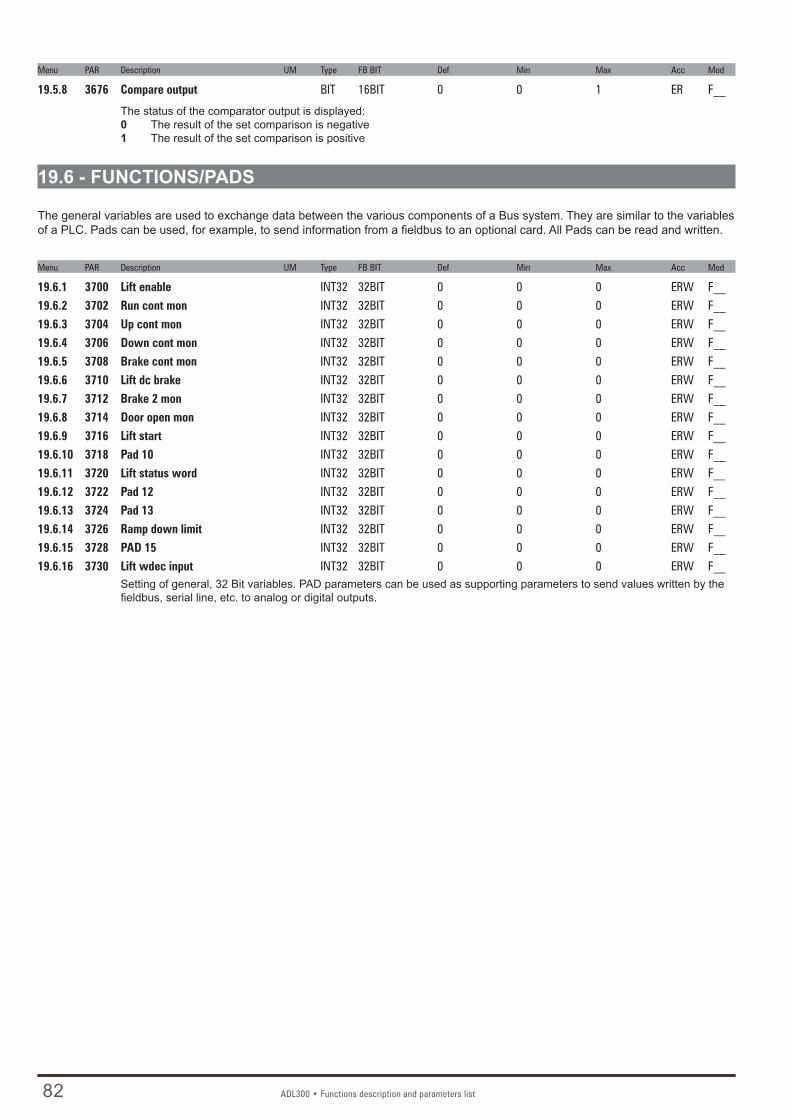
82 ADL300 • Functions description and parameters list
Menu PAR Description UM Type FB BIT Def Min Max Acc Mod
19.5.8 3676 Compare output BIT 16BIT 0 0 1 ER F__
The status of the comparator output is displayed:0 The result of the set comparison is negative1 The result of the set comparison is positive
19.6 - FUNCTIONS/PADS
The general variables are used to exchange data between the various components of a Bus system. They are similar to the variables of a PLC. Pads can be used, for example, to send information from a fieldbus to an optional card. All Pads can be read and written.
Menu PAR Description UM Type FB BIT Def Min Max Acc Mod
19.6.1 3700 Lift enable INT32 32BIT 0 0 0 ERW F__19.6.2 3702 Run cont mon INT32 32BIT 0 0 0 ERW F__19.6.3 3704 Up cont mon INT32 32BIT 0 0 0 ERW F__19.6.4 3706 Down cont mon INT32 32BIT 0 0 0 ERW F__19.6.5 3708 Brake cont mon INT32 32BIT 0 0 0 ERW F__19.6.6 3710 Lift dc brake INT32 32BIT 0 0 0 ERW F__19.6.7 3712 Brake 2 mon INT32 32BIT 0 0 0 ERW F__19.6.8 3714 Door open mon INT32 32BIT 0 0 0 ERW F__19.6.9 3716 Lift start INT32 32BIT 0 0 0 ERW F__19.6.10 3718 Pad 10 INT32 32BIT 0 0 0 ERW F__19.6.11 3720 Lift status word INT32 32BIT 0 0 0 ERW F__19.6.12 3722 Pad 12 INT32 32BIT 0 0 0 ERW F__19.6.13 3724 Pad 13 INT32 32BIT 0 0 0 ERW F__19.6.14 3726 Ramp down limit INT32 32BIT 0 0 0 ERW F__19.6.15 3728 PAD 15 INT32 32BIT 0 0 0 ERW F__19.6.16 3730 Lift wdec input INT32 32BIT 0 0 0 ERW F__
Setting of general, 32 Bit variables. PAD parameters can be used as supporting parameters to send values written by the fieldbus, serial line, etc. to analog or digital outputs.

ADL300 • Functions description and parameters list 83
19.7 - FUNCTIONS/DIRECTION COUNT
The “Change ride direction count” function monitors usage of the ropes or belts, signals when maintenance/replacement is needed, and locks the lift if limits of usage are reached. This function is reserved to lift maintenance personnel and is protected by a specific password. Rope usage is typically measured in “changes of direction”: the maximum number is specified on a certificate supplied by the rope manufacturer. A specific counter keeps count of direction changes and can be reset when the ropes are replaced. The following signals, inserted in the L_DIGSEL1 selection list, can be brought to a digital output: PAR 3420 Ropes change req mon, PAR 3422 Direction change mon and PAR 3424 Dir change cnt zero.
IN p
aram
eter
s
PAR 3400 Direction cnt enable>
ADL300
PAR 3414 Direction counter>
OUT
para
met
ers
Enable direction change function Direction change counter
PAR 3412 Ropes usage>
PAR 3408 Dir cnt password>
Ropes usage percentageCounter reset password
PAR 3416 Prev direct counter>
Residual previous set of ropesPAR 3402 Max direction cnt
>Max. no. direction changes PAR 3418 No of cnt reset
>No. ropes replacement
Dig
ital o
utpu
ts
[31] Rope change>
PAR 3404 Ropes change thr>
Ropes usage alarmPreventive usage threshold
PAR 3424 Dir change cnt zero>
Lift lock
PAR 3406 Direction cnt reset>
PAR 3422 Direction change mon>
Reset direction change counter Direction change counter
.
Firmware updateTo keep them from being overwritten when using Gefran eXpress, these parameters are not updated with the Write all target parameters operation.
Replacing the driveIf the drive is replaced, you can save the configuration of the “Direction change count” function on the keypad (PAR 3434 Save to keypad) and load it on the new drive (PAR 3436 Load from keypad).
PasswordAll of the parameters of this function, reserved to lift maintenance personnel, are protected by a specific password.The password is managed via parameters PAR 3408 Dir cnt password and PAR 3410 Dir cnt new password.
Menu PAR Description UM Type FB BIT Def Min Max Acc Mod
19.7.1 3400 Direction cnt enable ENUM Disable 0 1 ERW FVS0 Disable 1 EnableEnables the “Direction change count” function.
Menu PAR Description UM Type FB BIT Def Min Max Acc Mod
19.7.2 3402 Max direction cnt UINT32 0 0 2147483647 ERW FVS
Sets the maximum allowed number of direction changes.
Menu PAR Description UM Type FB BIT Def Min Max Acc Mod
19.7.3 3404 Ropes change thr perc UINT16 0 0 100 ERW FVS
Importante!

84 ADL300 • Functions description and parameters list
Sets a usage threshold beyond which the “Rope change” alarm is signalled to indicate that the ropes have to be replaced. When parameter 3412 Ropes usage exceeds this threshold, the drive keeps running but the alarm stays on to remind the operator to replace the ropes.
Menu PAR Description UM Type FB BIT Def Min Max Acc Mod
19.7.4 3406 Direction cnt reset ENUM Disable 0 1 ERW FVS0 Disable 1 Enable
Let you run a reset to return the direction change counter to the initial value of parameter 3402 Max direction cnt (value set by rope manufacturer).This operation is password-protected and must be run when the ropes are changed.
Executing this command causes the following:1. the value of counter 3414 Direction counter is copied to parameter 3416 Prev direct counter,2. the value of parameter 3414 No of cnt reset is incremented,3. counter 3414 Direction counter is reset to value 3402 Max direction cnt and consequently parameter 3412 Ropes
usage is reset to 0.
Menu PAR Description UM Type FB BIT Def Min Max Acc Mod
19.7.5 3408 Dir cnt password UINT16 0 0 9999 ERW FVS
This parameter is used to enter the password (max 4 numbers) to protect the “Direction change count” menu. The pass-word is displayed only when it is entered; when not in this mode the display shows 0.
When the password has been entered, you can change it by entering a new one in PAR 3410 Dir cnt new password..
The password is not reset when reloading default parameters and is also maintained when updating firmware.Attention: if you forget the password you have to contact Gefran Technical Service.
Menu PAR Description UM Type FB BIT Def Min Max Acc Mod
19.7.6 3410 Dir cnt new password UINT16 0 0 9999 ERW FVS
This parameter lets you change the password to replace the one entered in par 3408 Dir cnt password. A combination of a maximum of 4 numbers is allowed. To access this parameter, you have to enable the menu by entering the old password in PAR 3408.The password must be entered twice to be enabled.
Menu PAR Description UM Type FB BIT Def Min Max Acc Mod
19.7.7 3412 Ropes usage perc UINT16 16BIT 0 0 0 ER FVS
Displays the ropes usage counter (as percentage) of parameter 3402 Max direction cnt. When PAR 3412 = 100% (corresponds to PAR 3414 = 0), the ropes have reached their useful life and must be replaced: the drive finishes the current travel and then locks.By switching the drive off and back on you can run a single travel to bring the car to a better position for the procedure. To eliminate the lock condition, reset the direction change counter.
Menu PAR Description UM Type FB BIT Def Min Max Acc Mod
19.7.8 3414 Direction counter UINT32 32BIT 0 0 0 ER FVS
Displays the countdown of direction changes remaining until useful life of the ropes is reached. When PAR 3414 = “0” the ropes must be replaced (corresponds to PAR 3412 = 100%): the drive finishes the current travel and then locks.By switching the drive off and back on you can run a single travel to bring the car to a better position for the procedure. To eliminate the lock condition, reset the direction change counter (see PAR 3406 Direction cnt reset).
Menu PAR Description UM Type FB BIT Def Min Max Acc Mod
19.7.9 3416 Prev direct counter UINT32 32BIT 0 0 0 ER FVS
Displays the number of direction changes remaining on the previous set of ropes (value of PAR 3414 Direction counter is
Importante!

ADL300 • Functions description and parameters list 85
copied before reset). This number will remain fixed until the next replacement of the ropes.
Menu PAR Description UM Type FB BIT Def Min Max Acc Mod
19.7.10 3418 No of cnt reset UINT32 32BIT 0 0 0 ER FVS
Displays the number of rope changes made.
Menu PAR Description UM Type FB BIT Def Min Max Acc Mod
19.7.11 3420 Ropes change req mon BIT 16BIT 0 0 1 ER FVS
Activates when the percentage of rope usage (set in PAR 3412 Ropes usage) exceeds the set threshold (PAR 3404 Ropes change thr).This signal is inserted in the L_DIGSEL1 selection list and can be brought to a digital output.
Menu PAR Description UM Type FB BIT Def Min Max Acc Mod
19.7.12 3434 Save to keypad BIT 0 0 1 ERWZ FVS
Lets you save the configuration of the “Direction change count” function on the keypad.The set of parameters is saved in a dedicated area on the keypad, separate from that of the other parameters (PAR 590 Save par to keypad).
Menu PAR Description UM Type FB BIT Def Min Max Acc Mod
19.7.13 3436 Load from keypad BIT 0 0 1 ERWZ FVS
Lets you load the configuration of the “Direction change count” function saved on the keypad with PAR 3434 Save to key-pad on the new drive.

86 ADL300 • Functions description and parameters list
20 - COMMUNICATION 20.1 - COMMUNICATION/RS232
The ADL300 drive is provided with a standard port (9 pole sub-D connector: XS) for connecting the RS232 serial line used for drive-PC point-to-point communication (via the GF-eXpress configuration software).
Menu PAR Description UM Type FB BIT Def Min Max Acc Mod
20.1.1 3800 Drive address UINT16 1 1 255 ERW F__
Setting of the address to which the drive responds when connected to the RS232 serial line.
Menu PAR Description UM Type FB BIT Def Min Max Acc Mod
20.1.2 3802 Serial baudrate ENUM 38400 0 2 ERW F__
Setting of the RS232 serial communication speed (Baud Rate).0 9600 1 19200 2 38400
Menu PAR Description UM Type FB BIT Def Min Max Acc Mod
20.1.3 3810 Serial parameter ENUM None,8,1 0 3 ERW F__
Setting of the format of the RS232 serial line.0 None,8,1 1 None,8,2 2 Even,8,1 3 Odd,8,1
Menu PAR Description UM Type FB BIT Def Min Max Acc Mod
20.1.4 3804 Serial protocol ENUM Modbus 0 1 ERW F__
Setting of the serial communication protocol:0 Modbus 1 Jbus Setting to 0 selects the Modbus RTU (Remote Terminal Unit) serial communication protocol.Setting to 1 selects the Jbus serial communication protocol. The Jbus protocol is functionally identical to the Modbus, ex-cept for the different numbering of addresses: in the Modbus these start from zero (0000 = 1st address) while in the JBUS they start from one (0001 = 1st address) and maintain this difference throughout numbering.
Menu PAR Description UM Type FB BIT Def Min Max Acc Mod
20.1.5 3806 Serial delay ms UINT16 0 0 1000 ERW F__
Setting of the minimum delay between the drive receiving the last byte and starting its response. This delay avoids conflicts on the serial line when the RS232 interface that is used has not been pre-set for automatic Tx/Rx switching. The parameter only concerns the use of the standard RS232 serial line.Example: if the delay in Tx/Rx switching on the master is a maximum of 20ms, the Ser answer delay parameter must be set to at least 20ms: 22ms
Menu PAR Description UM Type FB BIT Def Min Max Acc Mod
20.1.6 3808 Serial swap data BIT 0 0 1 ERW F__
This parameter enables the exchange of the reading of the High and Low parts of the words for FLOAT type parameters when using the Modbus protocol.

ADL300 • Functions description and parameters list 87
20.2 - COMMUNICATION/FIELDBUS CONFIG Menu PAR Description UM Type FB BIT Def Min Max Acc Mod
20.2.1 4000 Fieldbus type ENUM Spento 0 2 ERW F__
Setting of the type of fieldbus to be used.0 Off 1 CANopen 10 DS417If set to 0 no fieldbus is selected.If set to 1 the CANopen fieldbus profile is selected.If set to 10 the DS417 fieldbus is selected.The CiA 417 is an MDPLC application. See the CiA 417 manual for configuration).
Menu PAR Description UM Type FB BIT Def Min Max Acc Mod
20.2.2 4004 Fieldbus baudrate ENUM 500k 0 4 ERW F__
Setting of the communication network speed (Baud Rate)0 Auto1 125k 2 250k 3 500k 4 1M
Menu PAR Description UM Type FB BIT Def Min Max Acc Mod
20.2.3 4006 Fieldbus address INT16 2 0 255 ERW F__
Setting of the node address of the drive when connected to the network.
Menu PAR Description UM Type FB BIT Def Min Max Acc Mod
20.2.4 4010 Fieldbus M->S enable ENUM Enable 0 1 ERWZ F__
Setting of fieldbus data updating. 0 Disable 1 EnableIf set to 0, the possibility of sending commands and references from the drive PLC via the fieldbus is disabled.If set to 1 the possibility of sending commands and references from the drive PLC via the fieldbus is enabled.
Menu PAR Description UM Type FB BIT Def Min Max Acc Mod
20.2.5 4012 Fieldbus alarm mode INT32 0 0 1 ERWZ F__
Setting of the Opt Bus Fault alarm generation mode.0 Disable1 Enable If set to 0 the alarm is only generated if the communication with the fieldbus is lost with the drive enabled..If set to 1 the alarm is generated when the communication with the fieldbus is lost even if the drive is disabled. .
Menu PAR Description UM Type FB BIT Def Min Max Acc Mod
20.2.6 4014 Fieldbus state ENUM Arresto 0 2 ER F__
The logic status of the fieldbus connection is displayed. The value depends on the type of bus that is used. 0 Stop 1 Pre operational 2 Operational

88 ADL300 • Functions description and parameters list
20.3 - COMMUNICATION/FIELDBUS M2S Menu PAR Description UM Type FB BIT Def Min Max Acc Mod
20.3.1 4020 Fieldbus M->S1 ipa FBM2SIPA 0 0 20000 ERW F__20.3.5 4030 Fieldbus M->S2 ipa FBM2SIPA 0 0 20000 ERW F__20.3.9 4040 Fieldbus M->S3 ipa FBM2SIPA 0 0 20000 ERW F__20.3.13 4050 Fieldbus M->S4 ipa FBM2SIPA 0 0 20000 ERW F__20.3.17 4060 Fieldbus M->S5 ipa FBM2SIPA 0 0 20000 ERW F__20.3.21 4070 Fieldbus M->S6 ipa FBM2SIPA 0 0 20000 ERW F__20.3.25 4080 Fieldbus M->S7 ipa FBM2SIPA 0 0 20000 ERW F__20.3.29 4090 Fieldbus M->S8 ipa FBM2SIPA 0 0 20000 ERW F__20.3.33 4100 Fieldbus M->S9 ipa FBM2SIPA 0 0 20000 ERW F__20.3.37 4110 Fieldbus M->S10 ipa FBM2SIPA 0 0 20000 ERW F__20.3.41 4120 Fieldbus M->S11 ipa FBM2SIPA 0 0 20000 ERW F__20.3.45 4130 Fieldbus M->S12 ipa FBM2SIPA 0 0 20000 ERW F__20.3.49 4140 Fieldbus M->S13 ipa FBM2SIPA 0 0 20000 ERW F__20.3.53 4150 Fieldbus M->S14 ipa FBM2SIPA 0 0 20000 ERW F__20.3.57 4160 Fieldbus M->S15 ipa FBM2SIPA 0 0 20000 ERW F__20.3.61 4170 Fieldbus M->S16 ipa FBM2SIPA 0 0 20000 ERW F__
Setting of the parameter to associate with the bus channel. The default setting is 0, which corresponds to no signal con-nected. If the parameter to be connected is a sorg (source), the channel and parameter can also be associated by modify-ing the sorg parameter in its menu. When setting a parameter, the format is also automatically set in the sys parameter.
Menu PAR Description UM Type FB BIT Def Min Max Acc Mod
20.3.2 4022 Fieldbus M->S1 sys ENUM Not assigned 0 10 ERW F__20.3.6 4032 Fieldbus M->S2 sys ENUM Not assigned 0 10 ERW F__20.3.10 4042 Fieldbus M->S3 sys ENUM Not assigned 0 10 ERW F__20.3.14 4052 Fieldbus M->S4 sys ENUM Not assigned 0 10 ERW F__20.3.18 4062 Fieldbus M->S5 sys ENUM Not assigned 0 10 ERW F__20.3.22 4072 Fieldbus M->S6 sys ENUM Not assigned 0 10 ERW F__20.3.26 4082 Fieldbus M->S7 sys ENUM Not assigned 0 10 ERW F__20.3.30 4092 Fieldbus M->S8 sys ENUM Not assigned 0 10 ERW F__20.3.34 4102 Fieldbus M->S9 sys ENUM Not assigned 0 10 ERW F__20.3.38 4112 Fieldbus M->S10 sys ENUM Not assigned 0 10 ERW F__20.3.42 4122 Fieldbus M->S11 sys ENUM Not assigned 0 10 ERW F__20.3.46 4132 Fieldbus M->S12 sys ENUM Not assigned 0 10 ERW F__20.3.50 4142 Fieldbus M->S13 sys ENUM Not assigned 0 10 ERW F__20.3.54 4152 Fieldbus M->S14 sys ENUM Not assigned 0 10 ERW F__20.3.58 4162 Fieldbus M->S15 sys ENUM Not assigned 0 10 ERW F__20.3.62 4172 Fieldbus M->S16 sys ENUM Not assigned 0 10 ERW F__
Setting of the format of the datum received on the channel. When the src parameter is programmed, the format is auto-matically programmed on the relative sys. If the src parameter is reset to null, the format does not change. The value of the format can be selected from the following list, according to the parameter selected as the source:
0 Not assigned 1 Count 16 2 Count 32 3 Fill 16 4 Fill 32 5 Mdplc 16 6 Mdplc 32 7 EU 8 Eu float 9 Par 16 10 Par 32
If set to 0 the channel is not assigned.If set to 1 the datum is assigned a 16-bit count.If set to 2 the datum is assigned a 32-bit count.

ADL300 • Functions description and parameters list 89
If set to 3 16 bits on the channel are reserved for the datum, not used.If set to 4 32 bits on the channel are reserved for the datum, not used.If set to 5 the datum is assigned a 16-bit count used by MDPLC.If set to 6 the datum is assigned a 32-bit count used by MDPLC.If set to 7 the datum is assigned engineering units on a 16-bit integer.If set to 8 the datum is assigned engineering units on a 32-bit integer.If set to 9, the datum is assigned a 16-bit integer engineering unit format not in real time (5-10ms)If set to 10 the datum is assigned a 32-bit integer engineering unit format or float format if the associated parameter is a float-type parameter not in real time (5-10ms).
Note! If the sys parameter is not assigned, none of the subsequent fieldbus channels are read, even if programmed.
Menu PAR Description UM Type FB BIT Def Min Max Acc Mod
20.3.3 4024 Fieldbus M->S1 mon INT32 32BIT 0 0 0 ER F__20.3.7 4034 Fieldbus M->S2 mon INT32 32BIT 0 0 0 ER F__20.3.11 4044 Fieldbus M->S3 mon INT32 32BIT 0 0 0 ER F__20.3.15 4054 Fieldbus M->S4 mon INT32 32BIT 0 0 0 ER F__20.3.19 4064 Fieldbus M->S5 mon INT32 32BIT 0 0 0 ER F__20.3.23 4074 Fieldbus M->S6 mon INT32 32BIT 0 0 0 ER F__20.3.27 4084 Fieldbus M->S7 mon INT32 32BIT 0 0 0 ER F__20.3.31 4094 Fieldbus M->S8 mon INT32 32BIT 0 0 0 ER F__20.3.35 4104 Fieldbus M->S9 mon INT32 32BIT 0 0 0 ER F__20.3.39 4114 Fieldbus M->S10 mon INT32 32BIT 0 0 0 ER F__20.3.43 4124 Fieldbus M->S11mon INT32 32BIT 0 0 0 ER F__20.3.47 4134 Fieldbus M->S12 mon INT32 32BIT 0 0 0 ER F__20.3.51 4144 Fieldbus M->S13 mon INT32 32BIT 0 0 0 ER F__20.3.55 4154 Fieldbus M->S14 mon INT32 32BIT 0 0 0 ER F__20.3.59 4164 Fieldbus M->S15 mon INT32 32BIT 0 0 0 ER F__20.3.63 4174 Fieldbus M->S16 mon INT32 32BIT 0 0 0 ER F__
The value received from the bus is displayed. This parameter must be associated with the src parameter to enable the M->S channel. The user may modify the M->S and by S->M sys parameters. The consistency of the sys with the parameter assigned to the channel is checked.A Fieldbus M->S X Mon parameter can only be assigned to a single “src”. If assigned to more than one src, an er-ror signal is generated during fieldbus initialization.
Menu PAR Description UM Type FB BIT Def Min Max Acc Mod
20.3.4 4026 Fieldbus M->S1 div FLOAT 1.0 1.0 1000.0 ERW F__20.3.8 4036 Fieldbus M->S2 div FLOAT 1.0 1.0 1000.0 ERW F__20.3.12 4046 Fieldbus M->S3 div FLOAT 1.0 1.0 1000.0 ERW F__20.3.16 4056 Fieldbus M->S4 div FLOAT 1.0 1.0 1000.0 ERW F__20.3.20 4066 Fieldbus M->S5 div FLOAT 1.0 1.0 1000.0 ERW F__20.3.24 4076 Fieldbus M->S6 div FLOAT 1.0 1.0 1000.0 ERW F__20.3.28 4086 Fieldbus M->S7 div FLOAT 1.0 1.0 1000.0 ERW F__20.3.32 4096 Fieldbus M->S8 div FLOAT 1.0 1.0 1000.0 ERW F__20.3.36 4106 Fieldbus M->S9 div FLOAT 1.0 1.0 1000.0 ERW F__20.3.40 4116 Fieldbus M->S10 div FLOAT 1.0 1.0 1000.0 ERW F__20.3.44 4126 Fieldbus M->S11 div FLOAT 1.0 1.0 1000.0 ERW F__20.3.48 4136 Fieldbus M->S12 div FLOAT 1.0 1.0 1000.0 ERW F__20.3.52 4146 Fieldbus M->S13 div FLOAT 1.0 1.0 1000.0 ERW F__20.3.56 4156 Fieldbus M->S14 div FLOAT 1.0 1.0 1000.0 ERW F__20.3.60 4166 Fieldbus M->S15 div FLOAT 1.0 1.0 1000.0 ERW F__20.3.64 4176 Fieldbus M->S16 div FLOAT 1.0 1.0 1000.0 ERW F__
The Div M->Sx fieldbus parameters can be used to increase the resolution of the datum sent on the bus to the drive in the corresponding channel in EU and EU_float exchange mode. The parameter value is used by the drive as the divider of the incoming datum, so that a number with decimal digits can be transferred.

90 ADL300 • Functions description and parameters list
Nota! You must check the size in bits of the datum that is sent to make sure that the maximum value in bits fits in a 16-bit integer. For exam-ple, if specifying the divider as “Fieldbus M->Sn div” = 1000, the maximum value that can be used for the exchanged datum is 32.768 (32768/1000).
Example : Div M->Sx fieldbus = 10, M->S1 fieldbus par = Ramp ref src 1, Sys M->S1 fieldbus = Eu. If the PLC sends the decimal value 1000 on the first word the value of ramp ref 1 on the drive is 1000/10 = 100.

ADL300 • Functions description and parameters list 91
20.4 - COMMUNICATION/FIELDBUS S2M Menu PAR Description UM Type FB BIT Def Min Max Acc Mod
20.4.1 4180 Fieldbus S->M1 ipa FBS2MIPA 0 0 20000 ERW F__20.4.5 4190 Fieldbus S->M2 ipa FBS2MIPA 0 0 20000 ERW F__20.4.9 4200 Fieldbus S->M3 ipa FBS2MIPA 0 0 20000 ERW F__20.4.13 4210 Fieldbus S->M4 ipa FBS2MIPA 0 0 20000 ERW F__20.4.17 4220 Fieldbus S->M5 ipa FBS2MIPA 0 0 20000 ERW F__20.4.21 4230 Fieldbus S->M6 ipa FBS2MIPA 0 0 20000 ERW F__20.4.25 4240 Fieldbus S->M7 ipa FBS2MIPA 0 0 20000 ERW F__20.4.29 4250 Fieldbus S->M8 ipa FBS2MIPA 0 0 20000 ERW F__20.4.33 4260 Fieldbus S->M9 ipa FBS2MIPA 0 0 20000 ERW F__20.4.37 4270 Fieldbus S->M10 ipa FBS2MIPA 0 0 20000 ERW F__20.4.41 4280 Fieldbus S->M11 ipa FBS2MIPA 0 0 20000 ERW F__20.4.45 4290 Fieldbus S->M12 ipa FBS2MIPA 0 0 20000 ERW F__20.4.49 4300 Fieldbus S->M13 ipa FBS2MIPA 0 0 20000 ERW F__20.4.53 4310 Fieldbus S->M14 ipa FBS2MIPA 0 0 20000 ERW F__20.4.57 4320 Fieldbus S->M15 ipa FBS2MIPA 0 0 20000 ERW F__20.4.61 4330 Fieldbus S->M16 ipa FBS2MIPA 0 0 20000 ERW F__
Setting of the parameter to associate with the bus channel. The default setting is 0, which corresponds to no signal con-nected. If the parameter to be connected is a sorg (source), the channel and parameter can also be associated by modify-ing the sorg parameter in its menu. When setting a parameter, the format is also automatically set in the sys parameter.
Menu PAR Description UM Type FB BIT Def Min Max Acc Mod
20.4.2 4182 Fieldbus S->M1 sys ENUM Not assigned 0 10 ERW F__20.4.6 4192 Fieldbus S->M2 sys ENUM Not assigned 0 10 ERW F__20.4.10 4202 Fieldbus S->M3 sys ENUM Not assigned 0 10 ERW F__20.4.14 4212 Fieldbus S->M4 sys ENUM Not assigned 0 10 ERW F__20.4.18 4222 Fieldbus S->M5 sys ENUM Not assigned 0 10 ERW F__20.4.22 4232 Fieldbus S->M6 sys ENUM Not assigned 0 10 ERW F__20.4.26 4242 Fieldbus S->M7 sys ENUM Not assigned 0 10 ERW F__20.4.30 4252 Fieldbus S->M8 sys ENUM Not assigned 0 10 ERW F__20.4.34 4262 Fieldbus S->M9 sys ENUM Not assigned 0 10 ERW F__20.4.38 4272 Fieldbus S->M10 sys ENUM Not assigned 0 10 ERW F__20.4.42 4282 Fieldbus S->M11 sys ENUM Not assigned 0 10 ERW F__20.4.46 4292 Fieldbus S->M12 sys ENUM Not assigned 0 10 ERW F__20.4.50 4302 Fieldbus S->M13 sys ENUM Not assigned 0 10 ERW F__20.4.54 4312 Fieldbus S->M14 sys ENUM Not assigned 0 10 ERW F__20.4.58 4322 Fieldbus S->M15 sys ENUM Not assigned 0 10 ERW F__20.4.62 4332 Fieldbus S->M16 sys ENUM Not assigned 0 10 ERW F__
Setting of the format of the datum sent to the channel. When the src parameter is programmed, the format is programmed as Eu or MDPLC 16. If the src parameter is reset to null, the datum format does not change. The value of the format can be selected from the following list:
0 Not assigned1 Count 16 2 Count 32 3 Fill 16 4 Fill 32 5 Mdplc 16 6 Mdplc 32 7 EU 8 Eu float 9 Par 16 10 Par 32
If set to 0 the channel is not assigned.If set to 1 the datum is assigned a 16-bit count.If set to 2 the datum is assigned a 32-bit count.If set to 3 16 bits on the channel are reserved for the datum, not used.

92 ADL300 • Functions description and parameters list
If set to 4 32 bits on the channel are reserved for the datum, not used.If set to 5 the datum is assigned a 16-bit count used by MDPLC.If set to 6 the datum is assigned a 32-bit count used by MDPLC.If set to 7 the datum is assigned engineering units on a 16-bit integer.If set to 8 the datum is assigned engineering units on a 32-bit integer.If set to 9, the datum is assigned a 16-bit integer engineering unit format not in real time (5-10ms)If set to 10 the datum is assigned a 32-bit integer engineering unit format or float format if the associated parameter is a float-type parameter not in real time (5-10ms).
Note! If the sys parameter is not assigned, none of the subsequent channels are transferred to the fieldbus, even if programmed.
Menu PAR Description UM Type FB BIT Def Min Max Acc Mod
20.4.3 4184 Dig Fieldbus S->M1 INT32 32BIT 0 0 0 ERW F__20.4.7 4194 Dig Fieldbus S->M2 INT32 32BIT 0 0 0 ERW F__20.4.11 4204 Dig Fieldbus S->M3 INT32 32BIT 0 0 0 ERW F__20.4.15 4214 Dig Fieldbus S->M4 INT32 32BIT 0 0 0 ERW F__20.4.19 4224 Dig Fieldbus S->M5 INT32 32BIT 0 0 0 ERW F__20.4.23 4234 Dig Fieldbus S->M6 INT32 32BIT 0 0 0 ERW F__20.4.27 4244 Dig Fieldbus S->M7 INT32 32BIT 0 0 0 ERW F__20.4.31 4254 Dig Fieldbus S->M8 INT32 32BIT 0 0 0 ERW F__20.4.35 4264 Dig Fieldbus S->M9 INT32 32BIT 0 0 0 ERW F__20.4.39 4274 Dig Fieldbus S->M10 INT32 32BIT 0 0 0 ERW F__20.4.43 4284 Dig Fieldbus S->M11 INT32 32BIT 0 0 0 ERW F__20.4.47 4294 Dig Fieldbus S->M12 INT32 32BIT 0 0 0 ERW F__20.4.51 4304 Dig Fieldbus S->M13 INT32 32BIT 0 0 0 ERW F__20.4.55 4314 Dig Fieldbus S->M14 INT32 32BIT 0 0 0 ERW F__20.4.59 4324 Dig Fieldbus S->M15 INT32 32BIT 0 0 0 ERW F__20.4.63 4334 Dig Fieldbus S->M16 INT32 32BIT 0 0 0 ERW F__
If associated with the relative src, the value of this parameter is sent to the bus.The user may modify the M->S and by S->M sys parameters. The consistency of the sys with the parameter assigned to the channel is checked.
Menu PAR Description UM Type FB BIT Def Min Max Acc Mod
20.4.4 4186 Fieldbus S->M1 mul FLOAT 1.0 1.0 1000.0 ERW F__20.4.8 4196 Fieldbus S->M2 mul FLOAT 1.0 1.0 1000.0 ERW F__20.4.12 4206 Fieldbus S->M3 mul FLOAT 1.0 1.0 1000.0 ERW F__20.4.16 4216 Fieldbus S->M4 mul FLOAT 1.0 1.0 1000.0 ERW F__20.4.20 4226 Fieldbus S->M5 mul FLOAT 1.0 1.0 1000.0 ERW F__20.4.24 4236 Fieldbus S->M6 mul FLOAT 1.0 1.0 1000.0 ERW F__20.4.28 4246 Fieldbus S->M7 mul FLOAT 1.0 1.0 1000.0 ERW F__20.4.32 4256 Fieldbus S->M8 mul FLOAT 1.0 1.0 1000.0 ERW F__20.4.36 4266 Fieldbus S->M9 mul FLOAT 1.0 1.0 1000.0 ERW F__20.4.40 4276 Fieldbus S->M10 mul FLOAT 1.0 1.0 1000.0 ERW F__20.4.44 4286 Fieldbus S->M11 mul FLOAT 1.0 1.0 1000.0 ERW F__20.4.48 4296 Fieldbus S->M12 mul FLOAT 1.0 1.0 1000.0 ERW F__20.4.52 4306 Fieldbus S->M13 mul FLOAT 1.0 1.0 1000.0 ERW F__20.4.56 4316 Fieldbus S->M14 mul FLOAT 1.0 1.0 1000.0 ERW F__20.4.60 4326 Fieldbus S->M15 mul FLOAT 1.0 1.0 1000.0 ERW F__20.4.64 4336 Fieldbus S->M16 mul FLOAT 1.0 1.0 1000.0 ERW F__
The “Fieldbus S->Mx mul” parameters are multipliers that the drive applies to the datum before sending it to the bus. It is therefore possible to increase the resolution of some values read in EU and EU_float mode, also using decimal digits.
Note! The drive does not check that the multiplied parameter expressed in bits fits in a 16-bit integer. You must make sure that the multiplier is com-patible with the maximum value of the exchanged parameter and that it does not exceed the maximum size of 32768.

ADL300 • Functions description and parameters list 93
Example: Fieldbus S->Mx mul = 10, S->M1 fieldbus par = Motor speed, Sys S->M1 fieldbus = Eu. If the motor is running at 100 rpm, the PLC reads the value 100 * 10 = 1000 on the first word that is exchanged.
20.5 - COMMUNICATION/WORD COMP Menu PAR Description UM Type FB BIT Def Min Max Acc Mod
20.5.1 4400 Word bit0 src LINK 16BIT 6000 0 16384 ERW F__20.5.2 4402 Word bit1 src LINK 16BIT 6000 0 16384 ERW F__20.5.3 4404 Word bit2 src LINK 16BIT 6000 0 16384 ERW F__20.5.4 4406 Word bit3 src LINK 16BIT 6000 0 16384 ERW F__20.5.5 4408 Word bit4 src LINK 16BIT 6000 0 16384 ERW F__20.5.6 4410 Word bit5 src LINK 16BIT 6000 0 16384 ERW F__20.5.7 4412 Word bit6 src LINK 16BIT 6000 0 16384 ERW F__20.5.8 4414 Word bit7 src LINK 16BIT 6000 0 16384 ERW F__20.5.9 4416 Word bit8 src LINK 16BIT 6000 0 16384 ERW F__20.5.10 4418 Word bit9 src LINK 16BIT 6000 0 16384 ERW F__20.5.11 4420 Word bit10 src LINK 16BIT 6000 0 16384 ERW F__20.5.12 4422 Word bit11 src LINK 16BIT 6000 0 16384 ERW F__20.5.13 4424 Word bit12 src LINK 16BIT 6000 0 16384 ERW F__20.5.14 4426 Word bit13 src LINK 16BIT 6000 0 16384 ERW F__20.5.15 4428 Word bit14 src LINK 16BIT 6000 0 16384 ERW F__20.5.16 4430 Word bit15 src LINK 16BIT 6000 0 16384 ERW F__
Selection of the origin (source) of the signal to be used for coding in Word comp. This function allows the user to compose a single word composed of 16 signals, each of which can be selected from among those listed in the “L_DIGSEL1” selec-tion list”.The values of the sectioned sizes are converted into a single word.
Word bit0 src
Word bit1 src
Word bit14 src
Word bit15 src
Word comp monWORD_0BIT_0
BIT_1
BIT_14
BIT_15
BIT_1
.........................
Menu PAR Description UM Type FB BIT Def Min Max Acc Mod
20.5.17 4432 Word comp mon UINT32 16BIT 0 0 0 ER F__
The hexadecimal value of the Word comp output is displayed.

94 ADL300 • Functions description and parameters list
20.6 - COMMUNICATION/WORD COMP Menu PAR Description UM Type FB BIT Def Min Max Acc Mod
20.6.1 4450 Dig word decomp UINT32 16BIT 0 0 0 ERW F__Setting of the digital input decoded by the “Word decomp” block.
Menu PAR Description UM Type FB BIT Def Min Max Acc Mod
20.6.2 4452 Word decomp src LINK 16BIT 4450 0 16384 ERW F__Selection of the origin (source) of the word to be decoded by the “Word decomp” block. Each bit that is part of the word to be decoded is associated with the output channel of the “Word decomp” block. The variables that can be used for this function can be selected from among those listed in the “L_WDECOMP” selection list”
Word decomp src Bit0 decomp monWORD_0 BIT_0
BIT_1
BIT_14
BIT_15
BIT_1
......... ................
Bit10 decomp mon
Bit14 decomp mon
Bit15 decomp mon
Menu PAR Description UM Type FB BIT Def Min Max Acc Mod
20.6.3 4454 Bit0 decomp mon BIT 16BIT 0 0 1 ER F__20.6.4 4456 Bit1 decomp mon BIT 16BIT 0 0 1 ER F__20.6.5 4458 Bit2 decomp mon BIT 16BIT 0 0 1 ER F__20.6.6 4460 Bit3 decomp mon BIT 16BIT 0 0 1 ER F__20.6.7 4462 Bit4 decomp mon BIT 16BIT 0 0 1 ER F__20.6.8 4464 Bit5 decomp mon BIT 16BIT 0 0 1 ER F__20.6.9 4466 Bit6 decomp mon BIT 16BIT 0 0 1 ER F__20.6.10 4468 Bit7 decomp mon BIT 16BIT 0 0 1 ER F__20.6.11 4470 Bit8 decomp mon BIT 16BIT 0 0 1 ER F__20.6.12 4472 Bit9 decomp mon BIT 16BIT 0 0 1 ER F__20.6.13 4474 Bit10 decomp mon BIT 16BIT 0 0 1 ER F__20.6.14 4476 Bit11 decomp mon BIT 16BIT 0 0 1 ER F__20.6.15 4478 Bit12 decomp mon BIT 16BIT 0 0 1 ER F__20.6.16 4480 Bit13 decomp mon BIT 16BIT 0 0 1 ER F__20.6.17 4482 Bit14 decomp mon BIT 16BIT 0 0 1 ER F__20.6.18 4484 Bit15 decomp mon BIT 16BIT 0 0 1 ER F__
The single bits that make up the selected word are displayed.

ADL300 • Functions description and parameters list 95
21 - ALARM CONFIG
In the ALARM CONFIG menu the type of effect any alarm signals have on the drive is determined:
- The alarm status is saved- How must the drive react to the alarm signal?- Auto restart- Alarm reset
For some alarms, behaviour can be configured separately for each signal, while for the others the Disable drive is executed. Indi-vidual signals can also be sent to a programmable digital output.
Activity Ignore The alarm is not included in the list of alarms, it is not included in the alarm log, it is not signalled on the digital outputs, no drive commands are modified.
Warning The alarm is included in the list of alarms, it is included in the alarm log, it is signalled on the digital outputs, the First alarm information is updated, the Alarm enabled information is updated, no drive commands are modified.
Disable Drive The alarm is included in the list of alarms, it is included in the alarm log, it is signalled on
the digital outputs, the First alarm information is updated, the Alarm enabled information is updated, a command is sent to stop and disable the motor, which stops due to inertia.
Stop The alarm is included in the list of alarms, it is included in the alarm log, it is signalled on the digital outputs, the First alarm information is updated, the Alarm enabled informa-tion is updated, a Stop command is sent. When the zero speed is reached the drive is disabled. If Ramp control mode is enabled, the drive moves to the zero speed with the set ramp time; when the Speed delay 0 signal is activated the drive is disabled. If Speed control mode is enabled, the drive moves to the zero speed with the maximum current possible; when the Speed delay 0 signal is activated the drive is disabled. If Torque control mode is enabled, the drive moves to the zero speed with the time set by the load; when the Speed delay 0 signal is activated the drive is disabled.
Fast stop The alarm is included in the list of alarms, it is included in the alarm log, it is signalled on
the digital outputs, the First alarm information is updated, the Alarm enabled information is updated, a Fast Stop command is sent. When the zero speed is reached the drive is disabled. If Ramp control mode is enabled, the drive moves to the zero speed with the set fast stop ramp time (deceleration time 3); when the Speed delay 0 signal is activated the drive is disabled. If Speed control mode is enabled, the drive moves to the zero speed with the maximum current possible; when the Speed delay 0 signal is activated the drive is disabled. If Torque control mode is enabled, the drive moves to the zero speed with the set load time; when the Speed delay 0 signal is activated the drive is disabled.
n alarms with Activity = Ignore or Warning can be enabled at the same time.If an alarm with Activity = Stop or Fast Stop is enabled and another alarm with an Activity other than Ignore or Warning is enabled, the drive stops and is disabled.Not all alarms allow the controlled stopping of the drive. The following table shows the possibility of setting the Activities for the individual alarm signals.
Alarm Ignore Warning Disable drive Stop Fast stop
ExtFlt ü ü ü ü ü
Motor OT ü ü ü ü üOverspeed ü ü ü ü üSpdRefLoss ü ü ü ü üSpdFbkLoss ü ü ü ü üDrive ovld ü ü ü ü üMotor ovld ü ü ü ü üBres ovld ü ü ü ü ü

96 ADL300 • Functions description and parameters list
Alarm Ignore Warning Disable drive Stop Fast stop
InAir ü ü ü ü üPhLoss ü ü ü ü üOpt Bus ü ü ü ü üMot PhLoss ü ü ü ü ü
Menu PAR Description UM Type FB BIT Def Min Max Acc Mod
21.1 4500 Fault reset src LINK 16BIT 6000 0 16384 RW F__
Selection of the origin (source) of the signal to be used for the command to reset the drive after an alarm. The terminal that can be used for this function can be selected from among those listed in the “L_DIGSEL2” selection list.
Menu PAR Description UM Type FB BIT Def Min Max Acc Mod
21.2 4502 ExtFlt src LINK 16BIT 6000 0 16384 RW F__
Selection of the origin (source) of the signal to be used as the input for the drive external fault alarm ExtFlt. The terminal that can be used for this function can be selected from among those listed in the “L_DIGSEL2” selection list.
Menu PAR Description UM Type FB BIT Def Min Max Acc Mod
21.3 4504 ExtFlt activity ENUM Disable 0 4 RW F__
Setting of the behaviour of the drive in the event of an external fault alarm ExtFlt. This alarm indicates the intervention of a drive external protection.0 Ignore1 Warning 2 Disable 3 Stop 4 Fast stop
Menu PAR Description UM Type FB BIT Def Min Max Acc Mod
21.4 4506 ExtFlt restart ENUM Disable 0 1 RW F__
Enabling of automatic restart after the external fault alarm ExtFlt 0 Disable 1 Enable
Menu PAR Description UM Type FB BIT Def Min Max Acc Mod
21.5 4508 ExtFlt restart time ms UINT16 1000 120 30000 RW F__
Setting of the time within which the External Fault alarm must be reset in order to perform automatic restart.
Menu PAR Description UM Type FB BIT Def Min Max Acc Mod
21.6 4510 ExtFlt holdoff ms UINT16 0 0 10000 RW F__
Setting of the delay between the signalling of the external fault alarm ExtFlt and enabling of the alarm. If an alarm condi-tion occurs, the drive will wait for the set time before blocking is enabled. If the alarm is removed within the set time, the drive will not indicate any alarm condition.
Menu PAR Description UM Type FB BIT Def Min Max Acc Mod
21.7 4520 MotorOT src LINK 16BIT 6000 0 16384 RW F__
Selection of the origin (source) of the signal to be used for the motor overtemperature alarm MotorOT. The terminal that can be used for this function can be selected from among those listed in the “L_DIGSEL2” selection list”.
Menu PAR Description UM Type FB BIT Def Min Max Acc Mod
21.8 4522 MotorOT activity ENUM Avvisa 0 4 RW F__
Setting of the behaviour of the drive in case of a motor overtemperature alarm MotorOT. This alarm indicates that the mo-tor temperature is too high.0 Ignore1 Warning 2 Disable 3 Stop 4 Fast stop

ADL300 • Functions description and parameters list 97
Menu PAR Description UM Type FB BIT Def Min Max Acc Mod
21.9 4524 MotorOT restart ENUM Disable 0 1 RW F__
Enabling of automatic restart after the motor overtemperature alarm MotorOT. 0 Disable 1 Enable
Menu PAR Description UM Type FB BIT Def Min Max Acc Mod
21.10 4526 MotorOT restart time ms UINT16 1000 120 30000 RW F__
Setting of the time within which the Motor Overtemperature alarm must be reset in order to perform automatic restart.
Menu PAR Description UM Type FB BIT Def Min Max Acc Mod
21.11 4528 MotorOT holdoff ms UINT16 1000 0 30000 RW F__
Setting of the delay between the signalling of the motor overtemperature alarm MotorOT and enabling of the alarm. If an alarm condition occurs, the drive will wait for the set time before enabling the alarm. If the alarm is removed within the set time, the drive will not indicate any alarm condition.
Menu PAR Description UM Type FB BIT Def Min Max Acc Mod
21.12 4540 Overspeed threshold rpm INT16 INT32 CALCI 0 CALCI RW F__
Setting of the threshold above which the overspeed alarm Overspeed is enabled.
Menu PAR Description UM Type FB BIT Def Min Max Acc Mod
21.13 4542 Overspeed activity ENUM Disable 0 4 RW F__
Setting of the behaviour of the drive in case of a motor overspeed alarm Overspeed. This alarm indicates that the motor speed has exceeded the threshold set in the Speed ref top lim and Speed ref bottom lim parameters in the COM-MANDS menu.
0 Ignore1 Warning 2 Disable 3 Stop 4 Fast stop
Menu PAR Description UM Type FB BIT Def Min Max Acc Mod
21.14 4544 Overspeed holdoff ms UINT16 0 0 5000 RW F__
Setting of the delay between the signalling of the motor overspeed alarm Overspeed and enabling of the alarm. If an alarm condition occurs, the drive will wait for the set time before enabling the alarm. If the alarm is removed within the set time, the drive will not indicate any alarm condition.
Menu PAR Description UM Type FB BIT Def Min Max Acc Mod
21.15 4550 SpdRefLoss threshold rpm INT16 100 0 CALCI RW F__
Setting of the threshold below which the speed reference loss alarm SpdRefLoss occurs .
Menu PAR Description UM Type FB BIT Def Min Max Acc Mod
21.16 4552 SpdRefLoss activity ENUM Avvisa 0 4 RW F__
Setting of the behaviour of the drive in case of a speed reference loss alarm SpdRefLoss. This alarm indicates that the difference between the speed regulator reference and the actual motor speed is more than 100 rpm. This alarm must be disabled (= 0 Ignore) when parameter 2354 is set to a value other than zero. This alarm must be disabled (= 1 Disable) when PAR 2132 is set to Digital FP or Digital F or Sinus.This alarm must be disabled (= 1 Disable) when PAR 2136 is set to Peripheral Encoder.
0 Ignore1 Warning 2 Disable 3 Stop 4 Fast stop
Menu PAR Description UM Type FB BIT Def Min Max Acc Mod
21.17 4554 SpdRefLoss holdoff ms UINT16 1000 0 10000 RW F__
The delay between the Speed ref loss alarm condition signal and activation of the actual alarm. If an alarm condition oc-curs, the drive will wait for the set time before enabling the alarm. If the alarm is removed within the set time, the drive will

98 ADL300 • Functions description and parameters list
not indicate any alarm condition.
Menu PAR Description UM Type FB BIT Def Min Max Acc Mod
21.18 4560 SpdFbkLoss activity ENUM Disable 0 4 RW F__
Drive behaviour in case of the Speed fbk loss alarm is displayed. This alarm indicates the loss of the encoder feedback signals. Each type of encoder generates the Speed fbk loss alarm differently (incremental signal error, absolute signal er-ror, serial error).0 Ignore1 Warning 2 Disable 3 Stop 4 Fast stopFor absolute Endat encoders and absolute Hiperface encoders, after the alarm is generated, the encoder reset command must be sent to the encoder: during this procedure the application verifies whether the encoder is signalling an encoder alarm condition to the drive and the alarm is acquired from this.The causes of the Speed fbk loss alarm and the information acquired from the encoder are shown in the SpdFbkLoss code parameter 2172.
Note! See menu 15.13 for further information.
Menu PAR Description UM Type FB BIT Def Min Max Acc Mod
21.19 4562 SpdFbkLoss holdoff ms UINT16 200 0 10000 RW F__
Setting of the delay between the signalling of the speed feedback loss alarm condition SpdFbkLoss and the enabling of the alarm. If an alarm condition occurs, the drive will wait for the set time before enabling the alarm. If the alarm is removed within the set time, the drive will not indicate any alarm condition.
Menu PAR Description UM Type FB BIT Def Min Max Acc Mod
21.20 4564 SpdFbkLoss threshold rpm INT16 5 3 CALCI RW FV_
If using incremental digital encoders in single-ended mode, this parameter sets the limit above which the drive executes the action set with parameter 4560 SpdFbkLoss activity.
Menu PAR Description UM Type FB BIT Def Min Max Acc Mod
21.21 4570 Drive ovld activity ENUM Disable 0 4 ERW F__
Setting of the behaviour of the drive in case of a drive overload alarm Drive ovld. This alarm indicates that the drive over-load threshold has been reached.0 Ignore1 Warning 2 Disable 3 Stop 4 Fast stop
Menu PAR Description UM Type FB BIT Def Min Max Acc Mod
21.22 4572 Motor ovld activity ENUM Avvisa 0 4 ERW F__
Setting of the behaviour of the drive in case of a motor overload alarm Motor ovld. This alarm indicates that the motor overload threshold has been reached.0 Ignore1 Warning 2 Disable 3 Stop 4 Fast stop
Menu PAR Description UM Type FB BIT Def Min Max Acc Mod
21.23 4574 Bres ovld activity ENUM Disable 0 4 ERW F__
Setting of the behaviour of the drive in case of a braking resistor overload alarm Bres ovld. This alarm indicates that the braking resistor overload threshold has been reached.0 Ignore1 Warning 2 Disable 3 Stop 4 Fast stop

ADL300 • Functions description and parameters list 99
Menu PAR Description UM Type FB BIT Def Min Max Acc Mod
21.24 4582 HTsens restart ENUM Disable 0 1 ERW F__
Enabling of automatic restart after the drive heatsink overtemperature alarm HTsens. 0 Disable 1 Enable
Menu PAR Description UM Type FB BIT Def Min Max Acc Mod
21.25 4584 HTsens restart time ms UINT16 20000 120 60000 ERW F__
Setting of the time within which the HT sensor alarm must be reset in order to perform automatic restart.
Menu PAR Description UM Type FB BIT Def Min Max Acc Mod
21.26 4600 InAir activity ENUM Arresto 0 4 ERW F__
Setting of the behaviour of the drive in case of an intake air overtemperature alarm InAir. This alarm indicates that the temperature of the intake cooling air is too high.0 Ignore1 Warning 2 Disable 3 Stop 4 Fast stop
Menu PAR Description UM Type FB BIT Def Min Max Acc Mod
21.27 4602 InAir restart ENUM Disable 0 1 ERW F__
Enabling of automatic restart after the intake air overtemperature alarm InAir. 0 Disable 1 Enable
Menu PAR Description UM Type FB BIT Def Min Max Acc Mod
21.28 4604 InAir restart time ms UINT16 1000 120 30000 ERW F__
Setting of the time within which the Intakeair OT alarm must be reset in order to perform automatic restart.
Menu PAR Description UM Type FB BIT Def Min Max Acc Mod
21.29 4606 InAir holdoff ms UINT16 10000 0 30000 ERW F__
Setting of the delay between the signalling of the intake air overtemperature alarm InAir and enabling of the alarm. If an alarm condition occurs, the drive will wait for the set time before enabling the alarm. If the alarm is removed within the set time, the drive will not indicate any alarm condition.
Menu PAR Description UM Type FB BIT Def Min Max Acc Mod
21.30 4610 Desat restart ENUM Disable 0 1 ERW F__
Enabling of automatic restart after the desaturation alarm Desat. This alarm indicates a short circuit between the motor phases or on the power bridge. 0 Disable 1 Enable
Menu PAR Description UM Type FB BIT Def Min Max Acc Mod
21.31 4612 Desat restart time ms UINT16 2000 1000 10000 ERW F__
Setting of the time within which the Desaturation alarm must be reset in order to perform automatic restart. (Time with alarm signal active + 1000 msec).
Menu PAR Description UM Type FB BIT Def Min Max Acc Mod
21.32 4620 IOverC restart ENUM Disable 0 1 ERW F__
Enabling of automatic restart after the drive Overcurrent alarm. This alarm indicates an overcurrent (or short circuit be-tween phases or towards the ground). 0 Disable 1 Enable
Menu PAR Description UM Type FB BIT Def Min Max Acc Mod
21.33 4622 IOverC restart time ms UINT16 2000 1000 10000 ERW F__

100 ADL300 • Functions description and parameters list
Setting of the time within which the Overcurrent alarm must be reset in order to perform automatic restart. (Time with alarm signal active + 1000 msec).
Menu PAR Description UM Type FB BIT Def Min Max Acc Mod
21.34 4630 OverV restart ENUM Disable 0 1 ERW F__
Enabling of automatic restart after the Overvoltage alarm. This alarm indicates an overvoltage on the intermediate circuit (DC link) 0 Disable 1 Enable
Menu PAR Description UM Type FB BIT Def Min Max Acc Mod
21.35 4632 OverV restart time ms UINT16 2000 1000 10000 ERW F__
Setting of the time within which the Overvoltage alarm must be reset in order to perform automatic restart. (Time with alarm signal active + 1000 msec).
Menu PAR Description UM Type FB BIT Def Min Max Acc Mod
21.36 4640 UnderV restart ENUM Enable 0 1 ERW F__
Enabling of automatic restart after the Undervoltage alarm. This alarm indicates an undervoltage on the intermediate circuit (DC link). 0 Disable 1 Enable
Menu PAR Description UM Type FB BIT Def Min Max Acc Mod
21.37 4642 UnderV restart time ms UINT16 1000 120 10000 ERW F__
Setting of the time within which the Undervoltage alarm must be reset in order to perform automatic restart. (Time with alarm signal active + 100 msec).
Menu PAR Description UM Type FB BIT Def Min Max Acc Mod
21.38 4650 UVRep attempts UINT16 5 0 1000 ERW F__
Setting of the maximum number of attempts at automatic restart after the Undervoltage alarm before a Mult Undervolt-age alarm is generated. If this parameter is set to 1000 an infinite number of attempts are available.
Menu PAR Description UM Type FB BIT Def Min Max Acc Mod
21.39 4652 UVRep delay s UINT16 240 0 300 ERW F__
Setting of the time within which, if no automatic restarts are executed after the Undervoltage alarm, the attempts counter is reset. In this way the number of attempts set in Underv res attempts are still available.
Menu PAR Description UM Type FB BIT Def Min Max Acc Mod
21.40 4660 PhLoss activity ENUM Disable 0 4 ERW F__
Setting of the behaviour of the drive in case of a no phase alarm. This alarm indicates the absence of a drive power supply phase.0 Ignore1 Warning 2 Disable 3 Stop 4 Fast stop
Menu PAR Description UM Type FB BIT Def Min Max Acc Mod
21.41 4662 PhLoss restart ENUM Disable 0 1 ERW F__
Enabling of automatic restart after the no phase alarm. 0 Disable 1 Enable
Menu PAR Description UM Type FB BIT Def Min Max Acc Mod
21.42 4664 PhLoss restart time ms UINT16 1000 120 10000 ERW F__
Setting of the time within which the Phase loss alarm must be reset in order to perform automatic restart. (Time with alarm signal active + 100 msec).

ADL300 • Functions description and parameters list 101
Menu PAR Description UM Type FB BIT Def Min Max Acc Mod
21.43 4668 PhLoss output test ENUM Enable 0 2 ERWZ F__
Enabling of the output phase loss test.0 Disable 1 Enable2 PowerupIf set to 0 the test is disableIf set to 1 the drive verifies the presence of all the output phases each time it receives the enable command.If set to 2 the drive only verifies the presence of all the output phases the first time the enable command is sent after pow-ering
Note! The motor brake must be closed while running this test!
Menu PAR Description UM Type FB BIT Def Min Max Acc Mod
21.44 4654 Mot PhLoss activity ENUM Ignore 0 4 ERW FVS
“Motor Phase Loss” function detect the drop of one phase connecting the drive to the motor. This function works both when the motor is rotating. To configure the Phase Loss function the parameters 4654-4656-4674 and 4678 are available.The “Motor phase loss” alarm signals the loss of a motor phase. This parameter manages the alarm activity.0 Ignore1 Warning 2 Disable 3 Stop 4 Fast stop
Menu PAR Description UM Type FB BIT Def Min Max Acc Mod
22.45 4656 Mot PhLoss holdoff ms UINT16 800 200 10000 ERW FVS
Represents the time the alarm condition has to persist before the alarm is actually generated.
Menu PAR Description UM Type FB BIT Def Min Max Acc Mod
22.46 4674 Mot PhLoss speed thr rpm INT16 10 10 32000 ERW FVS
In case of failure of the connection between a phase of the motor and the drive, the alarm signal is active when it is ex-ceeded the speed threshold set in this parameter.It can be used to mask the alarm at very low speed during the start and stop transients when external noise could cause false alarm tripping.
Menu PAR Description UM Type FB BIT Def Min Max Acc Mod
21.47 4678 Mot PhLoss code UINT32 0 0 0 ER FVS
The hexadecimal value contains information about the type of problem detected and the motor phase where there is the anomaly.
0x0001 Error detected on phase U with motor running 0x0002 Error detected on phase V with motor running 0x0004 Error detected on phase W with motor running 0x0008 Error detected on phase U with motor running and speed ref loss 0x0010 Error detected on phase V with motor running and speed ref loss 0x0020 Error detected on phase W with motor running and speed ref loss 0x0040 Error detected on phase U during magnetizing stage ( Asynchronous motor only ) 0x0080 Error detected on phase V during magnetizing stage ( Asynchronous motor only ) 0x0100 Error detected on phase W during magnetizing stage ( Asynchronous motor only ) 0x0200 Error detected on phase U with motor disabled (Asynchronous motor only) 0x0400 Error detected on phase V with motor disabled (Asynchronous motor only) 0x0800 Error detected on phase W with motor disabled (Asynchronous motor only)
In some cases it is possible that more bit are showed at the same time. Depending on the type of fault, in fact, if the inter-ruption of one phase makes that even in the other two there is no more current circulation, the dis¬played code indicates the absence of all three phases, while being just one connection failed.
Menu PAR Description UM Type FB BIT Def Min Max Acc Mod
21.48 4670 Optionbus activity ENUM Disable 0 4 ERW F__
Setting of the behaviour of the drive in case of an “Opt Bus Fault” alarm.

102 ADL300 • Functions description and parameters list
0 Ignore1 Warning 2 Disable 3 Stop 4 Fast stop
Menu PAR Description UM Type FB BIT Def Min Max Acc Mod
21.49 4680 GroundFault thr perc FLOAT 10.0 0.0 150.0 ERWS F__
Setting of the threshold for the ground short circuit alarm Ground Fault.
Menu PAR Description UM Type FB BIT Def Min Max Acc Mod
21.50 4700 Alarm dig sel 1 ENUM Nessun allarme 0 40 ERW F__
21.51 4702 Alarm dig sel 2 ENUM Nessun allarme 0 40 ERW F__
21.52 4704 Alarm dig sel 3 ENUM Nessun allarme 0 40 ERW F__
21.53 4706 Alarm dig sel 4 ENUM Nessun allarme 0 40 ERW F__
Setting of the alarm signal to enable on a digital output. The digital output is selected using parameters Alm dig out mon 1÷4, which can be enabled in the L_DIGSEL1 selection list.
0 No alarm 1 Overvoltage 2 Undervoltage 3 Ground fault 4 Overcurrent 5 Desaturation 6 MultiUndervolt 7 MultiOvercurr 8 MultiDesat 9 Heatsink OT 10 HeatsinkS OTUT 11 Intakeair OT 12 Motor OT 13 Drive overload 14 Motor overload 15 Bres overload 16 Phaseloss 17 Opt Bus fault 18 Opt 1 IO fault 19 Opt 2 IO fault 20 Opt Enc fault 21 External fault 22 Speed fbk loss 23 Overspeed 24 Speed ref loss 25 Emg stop alarm 26 Power down 27 Phaseloss out 28 OV safety29 Safety failure30 Mot phase loss31 Ropes change32 Not Used33 Plc1 fault 34 Plc2 fault 35 Plc3 fault 36 Plc4 fault 37 Plc5 fault 38 Plc6 fault 39 Plc7 fault 40 Plc8 fault
Menu PAR Description UM Type FB BIT Def Min Max Acc Mod
21.54 4720 Alm autoreset time s FLOAT 0.0 0.0 60.0 ERW F__
Setting of the time interval that must pass before executing an automatic reset.If no alarms are enabled the drive is set to restart.If some alarms are still enabled the drive is set to execute a new attempt at automatic reset.

ADL300 • Functions description and parameters list 103
At each attempted reset a counter increases. If the limit set in the Alm autoreset number parameter is reached the drive is set to make no more attempts at reset and waits for a user reset.The counter is set to zero when an automatic reset or user reset is performed and no alarms are enabled.If the parameter is 0 the function is disabled.
Menu PAR Description UM Type FB BIT Def Min Max Acc Mod
21.55 4722 Alm autoreset number UINT16 20 0 100 ERW F__
Setting of the maximum number of attempted automatic resets.

104 ADL300 • Functions description and parameters list
23 - ALARM LOG
This is the menu in which the log of previous alarms is saved, with the time the alarm occurred (in relation to the Time drive power on parameter). The alarms are displayed starting from the most recent (No. 1) up to the furthest back in time (No. 30). Up to 30 alarm signals can be displayed. The sub-code is used by service technicians to identify the specific type of alarm. Press the ▲ and ▼ keys to scroll the screen pages of the alarm log. The alarm log cannot be deleted.
3 SpdFbkLoss
4 Overspeed
110:20 0000H
109:25 0000H
1 PhaseLoss
2 Undervoltage
110:32 0000H
110:25 0000H
Alarm description
Sub-code
Alarm number
Time alarm
occurred

ADL300 • Functions description and parameters list 105
PARAMETERS ON SELECTION LISTS, BUT NOT DISPLAYED ON KEYPAD
This list reports the parameters that are not displayed in the keyboard while they are part of the selection lists. These parameters can be used as SOURCE of the input signals for the function block. (Refer to section A – Programming).
Menu PAR Description UM Type FB BIT Def Min Max Acc Mod
- 262 Motor speed nofilter rpm INT16 16BIT 0 0 0 ER F__
This parameter indicates the unfiltered motor speed.
Menu PAR Description UM Type FB BIT Def Min Max Acc Mod
- 362 Drive overload trip BIT 16BIT 0 0 1 ER F__
This signal indicates that the drive is in the overload alarm condition.
Menu PAR Description UM Type FB BIT Def Min Max Acc Mod
- 366 Drive overload 80% BIT 16BIT 0 0 1 ER F__
This signal indicates that the drive has reached 80% of the thermal image accumulator (drive overload).
Menu PAR Description UM Type FB BIT Def Min Max Acc Mod
- 626 Ramp ref out mon rpm INT16 16BIT 0 0 0 ER F__
This parameter displays the reference value output of the ramp remference function block.
Menu PAR Description UM Type FB BIT Def Min Max Acc Mod
- 760 Ramp out mon rpm INT16 16BIT 0 0 0 ER F__
This parameter displays the reference value output of the ramp function block.
Menu PAR Description UM Type FB BIT Def Min Max Acc Mod
- 764 Ramp acc state BIT 16BIT 0 0 1 ER F__
This signal indicates whether the acceleration ramp is active.
Menu PAR Description UM Type FB BIT Def Min Max Acc Mod
- 766 Ramp dec state BIT 16BIT 0 0 1 ER F__
This signal indicates whether the deceleration ramp is active.
Menu PAR Description UM Type FB BIT Def Min Max Acc Mod
- 934 Ref is 0 BIT 16BIT 0 0 1 ER F__
This signal is active when the reference is below the limit set in parameter 930 Reference 0 threshold.
Menu PAR Description UM Type FB BIT Def Min Max Acc Mod
- 936 Ref is 0 delay BIT 16BIT 0 0 1 ER F__
This parameter is active when the reference is below the threshold set in parameter 930 Reference 0 threshold. The signal is enabled after the delay set with parameter 932 Reference delay 0.
Menu PAR Description UM Type FB BIT Def Min Max Acc Mod
- 944 Speed is 0 BIT 16BIT 0 0 1 ER F__
This parameter is active when the speed is below the threshold set in parameter 940 Speed 0 threshold.
Menu PAR Description UM Type FB BIT Def Min Max Acc Mod
- 946 Speed is 0 delay BIT 16BIT 0 0 1 ER F__
This signal is active when the reference is below the threshold set in parameter 940 Speed 0 threshold. The signal is activated after the delay set in parameter 942 Speed 0 delay.
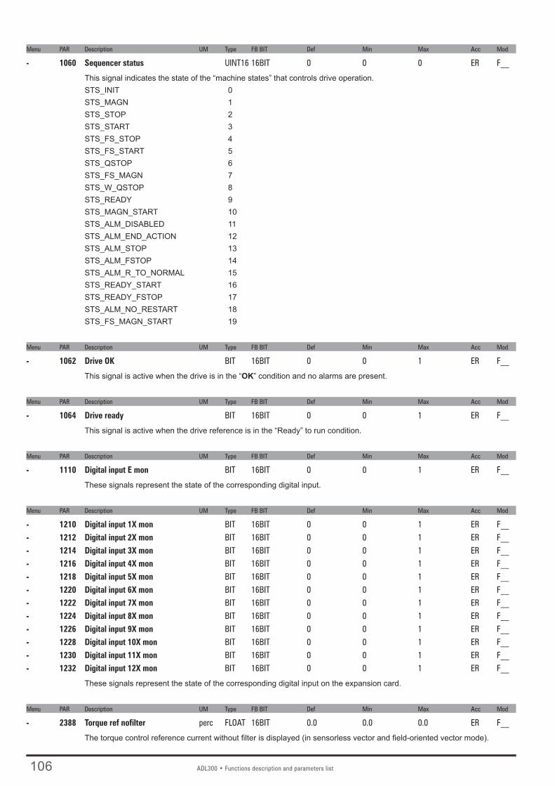
106 ADL300 • Functions description and parameters list
Menu PAR Description UM Type FB BIT Def Min Max Acc Mod
- 1060 Sequencer status UINT16 16BIT 0 0 0 ER F__
This signal indicates the state of the “machine states” that controls drive operation.STS_INIT 0STS_MAGN 1STS_STOP 2STS_START 3STS_FS_STOP 4STS_FS_START 5STS_QSTOP 6STS_FS_MAGN 7STS_W_QSTOP 8STS_READY 9STS_MAGN_START 10STS_ALM_DISABLED 11STS_ALM_END_ACTION 12STS_ALM_STOP 13STS_ALM_FSTOP 14STS_ALM_R_TO_NORMAL 15STS_READY_START 16STS_READY_FSTOP 17STS_ALM_NO_RESTART 18STS_FS_MAGN_START 19
Menu PAR Description UM Type FB BIT Def Min Max Acc Mod
- 1062 Drive OK BIT 16BIT 0 0 1 ER F__
This signal is active when the drive is in the “OK” condition and no alarms are present.
Menu PAR Description UM Type FB BIT Def Min Max Acc Mod
- 1064 Drive ready BIT 16BIT 0 0 1 ER F__
This signal is active when the drive reference is in the “Ready” to run condition.
Menu PAR Description UM Type FB BIT Def Min Max Acc Mod
- 1110 Digital input E mon BIT 16BIT 0 0 1 ER F__
These signals represent the state of the corresponding digital input.
Menu PAR Description UM Type FB BIT Def Min Max Acc Mod
- 1210 Digital input 1X mon BIT 16BIT 0 0 1 ER F__- 1212 Digital input 2X mon BIT 16BIT 0 0 1 ER F__- 1214 Digital input 3X mon BIT 16BIT 0 0 1 ER F__- 1216 Digital input 4X mon BIT 16BIT 0 0 1 ER F__- 1218 Digital input 5X mon BIT 16BIT 0 0 1 ER F__- 1220 Digital input 6X mon BIT 16BIT 0 0 1 ER F__- 1222 Digital input 7X mon BIT 16BIT 0 0 1 ER F__- 1224 Digital input 8X mon BIT 16BIT 0 0 1 ER F__- 1226 Digital input 9X mon BIT 16BIT 0 0 1 ER F__- 1228 Digital input 10X mon BIT 16BIT 0 0 1 ER F__- 1230 Digital input 11X mon BIT 16BIT 0 0 1 ER F__- 1232 Digital input 12X mon BIT 16BIT 0 0 1 ER F__
These signals represent the state of the corresponding digital input on the expansion card.
Menu PAR Description UM Type FB BIT Def Min Max Acc Mod
- 2388 Torque ref nofilter perc FLOAT 16BIT 0.0 0.0 0.0 ER F__
The torque control reference current without filter is displayed (in sensorless vector and field-oriented vector mode).

ADL300 • Functions description and parameters list 107
Menu PAR Description UM Type FB BIT Def Min Max Acc Mod
- 3214 Motor overload trip BIT 16BIT 0 0 1 ER F__
This signal is active when the drive is in the motor overload alarm condition.
Menu PAR Description UM Type FB BIT Def Min Max Acc Mod
- 3262 Bres overload trip BIT 16BIT 0 0 1 ER F__
This signal is active when the drive is in the braking resistor overload alarm condition.
Menu PAR Description UM Type FB BIT Def Min Max Acc Mod
- 3422 Direction change mon BIT 16BIT 0 0 1 ER FVS
This signal stays on for one second each time the drive detects a direction change and thus decrements the counter.This signal is inserted in the L_DIGSEL1 selection list and can be brought to a digital output.
Menu PAR Description UM Type FB BIT Def Min Max Acc Mod
- 3424 Dir change cnt zero BIT 16BIT 0 0 1 ER FVS
This signal activates when the drive is locked because 3414 Direction counter has reached 0.This signal is inserted in the L_DIGSEL1 selection list and can be brought to a digital output.
Menu PAR Description UM Type FB BIT Def Min Max Acc Mod
- 4708 Alm dig out mon 1 BIT 16BIT 0 0 1 ER F__
This signal is activated when the alarm configured in parameter 4700 alarm dig sel 1 is active.
Menu PAR Description UM Type FB BIT Def Min Max Acc Mod
- 4710 Alm dig out mon 2 BIT 16BIT 0 0 1 ER F__
This signal is activated when the alarm configured in parameter 4702 alarm dig sel 2 is active.
Menu PAR Description UM Type FB BIT Def Min Max Acc Mod
- 4712 Alm dig out mon 3 BIT 16BIT 0 0 1 ER F__
This signal is activated when the alarm configured in parameter 4704 alarm dig sel 3 is active.
Menu PAR Description UM Type FB BIT Def Min Max Acc Mod
- 4714 Alm dig out mon 4 BIT 16BIT 0 0 1 ER F__
This signal is activated when the alarm configured in parameter 4706 alarm dig sel 4 is active.
Menu PAR Description UM Type FB BIT Def Min Max Acc Mod
- 4770 First alarm UINT32 16BIT 0 0 0 ERW F__
This parameter displays the first alarm to be activated..0 No alarm 1 Overvoltage 2 Undervoltage 3 Ground fault 4 Overcurrent 5 Desaturation 6 MultiUndervolt 7 MultiOvercurr 8 MultiDesat 9 Heatsink OT 10 HeatsinkS OTUT 11 Intakeair OT 12 Motor OT 13 Drive overload 14 Motor overload 15 Bres overload 16 Phaseloss 17 Opt Bus fault 18 Opt 1 IO fault 19 Opt 2 IO fault 20 Opt Enc fault

108 ADL300 • Functions description and parameters list
21 External fault 22 Speed fbk loss 23 Overspeed 24 Speed ref loss 25 Emg stop alarm 26 Power down 27 Phaseloss out 28 OV safety29 Safety failure30 Mot phase loss31 Ropes change32 Not Used33 Plc1 fault 34 Plc2 fault 35 Plc3 fault 36 Plc4 fault 37 Plc5 fault 38 Plc6 fault 39 Plc7 fault 40 Plc8 fault
Menu PAR Description UM Type FB BIT Def Min Max Acc Mod
- 4780 Alarm PLC UINT16 0 0 0 ER F__
This parameter displays the state of the alarms generated by the application written with the internal PLC.
Bit Description0 1 = PLC 1 fault active 1 1 = PLC 2 fault active2 1 = PLC 3 fault active 3 1 = PLC 4 fault active 4 1 = PLC 5 fault active 5 1 = PLC 6 fault active 6 1 = PLC 7 fault active 7 1 = PLC 8 fault active
Menu PAR Description UM Type FB BIT Def Min Max Acc Mod
- 6000 Null UINT32 32BIT 0 0 0 ER F__
This signal forces the variable to the zero level (always disabled).
Menu PAR Description UM Type FB BIT Def Min Max Acc Mod
- 6002 One UINT32 32BIT 1 1 1 ER F__
This signal forces the variable to level one (always active)..
Menu PAR Description UM Type FB BIT Def Min Max Acc Mod
- 6006 Current limit state BIT 16BIT 0 0 1 ER F__
This signal is activated when the drive is in the current limit condition.
Menu PAR Description UM Type FB BIT Def Min Max Acc Mod
- 6372 DS417 status word UINT16 16BIT 0 0 65535 ER FVS
This parameter displays the status word according to the DS417 Profile. For more information reference should be made to the fieldbus manual.

ADL300 • Selection lists 109
PAR Description Menu PAR Description Menu PAR Description Menu
C - SELECTION LISTS
L_ANOUT 6000 Null (*) 626 Ramp ref out mon (*) 760 Ramp out mon (*) 664 Speed setpoint 1.5260 Motor speed 1.6262 Motor speed nofilter (*) 2150 Encoder speed 15.17250 Output current 1.1252 Output voltage 1.2254 Output frequency 1.3280 Torque current ref 1.9282 Magnet current ref 1.10284 Torque current 1.11286 Magnet current 1.122360 Torque climPos Inuse 18.52362 Torque climNeg Inuse 18.62386 Torque ref 18.102388 Torque ref nofilter (*) 270 DC link voltage 1.73104 Inertia comp mon 19.1.31600 Analog input 1X mon 12.11650 Analog input 2X mon 12.12368 Drive overload accum 1.143212 Motor overload accum 1.133260 Bres overload accum 1.152232 Spd reg P gain Inuse 16.162234 Spd reg I gain Inuse 16.174024 Fieldbus M->S1 mon 20.3.34034 Fieldbus M->S2 mon 20.3.74044 Fieldbus M->S3 mon 20.3.114054 Fieldbus M->S4 mon 20.3.154064 Fieldbus M->S5 mon 20.3.194074 Fieldbus M->S6 mon 20.3.234084 Fieldbus M->S7 mon 20.3.274094 Fieldbus M->S8 mon 20.3.314104 Fieldbus M->S9 mon 20.3.354114 Fieldbus M->S10 mon 20.3.394124 Fieldbus M->S11 mon 20.3.434134 Fieldbus M->S12 mon 20.3.474144 Fieldbus M->S13 mon 20.3.514154 Fieldbus M->S14 mon 20.3.554164 Fieldbus M->S15 mon 20.3.594174 Fieldbus M->S16 mon 20.3.633700 Lift enable 19.6.13702 Run cont mon 19.6.23704 Up cont mon 19.6.33706 Down cont mon 19.6.43708 Brake cont mon 19.6.5 3710 Lift dc brake 19.6.63712 Brake 2 mon 19.6.7 3714 Door open mon 19.6.8 3716 Lift start 19.6.9 3718 Pad 10 19.6.103720 Lift status word 19.6.113722 Pad 12 19.6.123724 Pad 13 19.6.133726 Ramp down limit 19.6.143728 PAD 15 19.6.15 3730 Lift wdec input 19.6.16 5008 Test gen out 23.1.5
L_CMP XXXX (1)
626 Ramp ref out mon (*)
760 Ramp out mon (*) 664 Speed setpoint 1.5260 Motor speed 1.6262 Motor speed nofilter (*) 2150 Encoder speed 15.17250 Output current 1.1252 Output voltage 1.2254 Output frequency 1.3280 Torque current ref 1.9282 Magnet current ref 1.10284 Torque current 1.11286 Magnet current 1.122386 Torque ref 18.102388 Torque ref nofilter (*) 270 DC link voltage 1.71600 Analog input 1X mon 12.11650 Analog input 2X mon 12.12368 Drive overload accum 1.143212 Motor overload accum 1.133260 Bres overload accum 1.154024 Fieldbus M->S1 mon 20.3.34034 Fieldbus M->S2 mon 20.3.74044 Fieldbus M->S3 mon 20.3.114054 Fieldbus M->S4 mon 20.3.154064 Fieldbus M->S5 mon 20.3.194074 Fieldbus M->S6 mon 20.3.234084 Fieldbus M->S7 mon 20.3.274094 Fieldbus M->S8 mon 20.3.314104 Fieldbus M->S9 mon 20.3.354114 Fieldbus M->S10 mon 20.3.394124 Fieldbus M->S11 mon 20.3.434134 Fieldbus M->S12 mon 20.3.474144 Fieldbus M->S13 mon 20.3.514154 Fieldbus M->S14 mon 20.3.554164 Fieldbus M->S15 mon 20.3.594174 Fieldbus M->S16 mon 20.3.633700 Lift enable 19.6.13702 Run cont mon 19.6.23704 Up cont mon 19.6.33706 Down cont mon 19.6.43708 Brake cont mon 19.6.5 3710 Lift dc brake 19.6.63712 Brake 2 mon 19.6.7 3714 Door open mon 19.6.8 3716 Lift start 19.6.9 3718 Pad 10 19.6.103720 Lift status word 19.6.113722 Pad 12 19.6.123724 Pad 13 19.6.133726 Ramp down limit 19.6.143728 PAD 15 19.6.15 3730 Lift wdec input 19.6.16 (1) the XXXX parameter changes according to the src parameter used:
3660 Compare input 1 src (1) = 3650 Dig compare input 1 19.5.1
3662 Compare input 2 src (1) = 3652 Dig compare input 2 19.5.2
L_DIGSEL1 6000 Null (*) 6002 One (*) 1110 Digital input E mon (*) 1210 Digital input 1X mon (*) 1212 Digital input 2X mon (*)
1214 Digital input 3X mon (*) 1216 Digital input 4X mon (*) 1218 Digital input 5X mon (*) 1220 Digital input 6X mon (*) 1222 Digital input 7X mon (*) 1224 Digital input 8X mon (*) 1226 Digital input 9X mon (*) 1228 Digital input10X mon (*) 1230 Digital input11X mon (*) 1232 Digital input12X mon (*) 1062 Drive OK (*) 1064 Drive ready (*) 934 Ref is 0 (*) 936 Ref is 0 delay (*) 944 Speed is 0 (*) 946 Speed is 0 delay (*) 1066 Enable state mon 1.161068 Start state mon 1.171070 FastStop state mon 1.181024 Enable cmd mon 9.91026 Start cmd mon 9.101028 FastStop cmd mon 9.114708 Alm dig out mon 1 (*) 4710 Alm dig out mon 2 (*) 4712 Alm dig out mon 3 (*) 4714 Alm dig out mon 4 (*) 362 Drive overload trip (*) 3214 Motor overload trip (*) 3262 Bres overload trip (*) 366 Drive overload 80% (*) 4454 Bit0 decomp mon 20.6.34456 Bit1 decomp mon 20.6.44458 Bit2 decomp mon 20.6.54460 Bit3 decomp mon 20.6.64462 Bit4 decomp mon 20.6.74464 Bit5 decomp mon 20.6.84466 Bit6 decomp mon 20.6.94468 Bit7 decomp mon 20.6.104470 Bit8 decomp mon 20.6.114472 Bit9 decomp mon 20.6.124474 Bit10 decomp mon 20.6.134476 Bit11 decomp mon 20.6.144478 Bit12 decomp mon 20.6.154480 Bit13 decomp mon 20.6.164482 Bit14 decomp mon 20.6.174484 Bit15 decomp mon 20.6.183700 Lift enable 19.6.13702 Run cont mon 19.6.23704 Up cont mon 19.6.33706 Down cont mon 19.6.43708 Brake cont mon 19.6.5 3710 Lift dc brake 19.6.63712 Brake 2 mon 19.6.7 3714 Door open mon 19.6.8 3716 Lift start 19.6.9 3718 Pad 10 19.6.103720 Lift status word 19.6.113722 Pad 12 19.6.123724 Pad 13 19.6.133726 Ramp down limit 19.6.143728 PAD 15 19.6.15 3730 Lift wdec input 19.6.16 6006 Current limit state (*) 764 Ramp acc state (*) 766 Ramp dec state (*) 4780 Alarm PLC (*) 3676 Compare output 19.5.83420 Ropes change req mon 19.7.11

110 ADL300 • Selection lists
PAR Description Menu PAR Description Menu PAR Description Menu
3422 Direction change mon (*) 3424 Dir change cnt zero (*)
L_DIGSEL2 6000 Null (*) 6002 One (*) 1110 Digital input E mon (*) 1210 Digital input 1X mon (*) 1212 Digital input 2X mon (*) 1214 Digital input 3X mon (*) 1216 Digital input 4X mon (*) 1218 Digital input 5X mon (*) 1220 Digital input 6X mon (*) 1222 Digital input 7X mon (*) 1224 Digital input 8X mon (*) 1226 Digital input 9X mon (*) 1228 Digital input10X mon (*) 1230 Digital input11X mon (*) 1232 Digital input12X mon (*) 4454 Bit0 decomp mon 20.6.34456 Bit1 decomp mon 20.6.44458 Bit2 decomp mon 20.6.54460 Bit3 decomp mon 20.6.64462 Bit4 decomp mon 20.6.74464 Bit5 decomp mon 20.6.84466 Bit6 decomp mon 20.6.94468 Bit7 decomp mon 20.6.104470 Bit8 decomp mon 20.6.114472 Bit9 decomp mon 20.6.124474 Bit10 decomp mon 20.6.134476 Bit11 decomp mon 20.6.144478 Bit12 decomp mon 20.6.154480 Bit13 decomp mon 20.6.164482 Bit14 decomp mon 20.6.174484 Bit15 decomp mon 20.6.183700 Lift enable 19.6.13702 Run cont mon 19.6.23704 Up cont mon 19.6.33706 Down cont mon 19.6.43708 Brake cont mon 19.6.5 3710 Lift dc brake 19.6.63712 Brake 2 mon 19.6.7 3714 Door open mon 19.6.8 3716 Lift start 19.6.9 3718 Pad 10 19.6.103720 Lift status word 19.6.113722 Pad 12 19.6.123724 Pad 13 19.6.133726 Ramp down limit 19.6.143728 PAD 15 19.6.15 3730 Lift wdec input 19.6.16 3676 Compare output 19.5.8
L_DIGSEL3 XXXX (2)
6000 Null (*) 1218 Digital input 5X mon (*) 1220 Digital input 6X mon (*) 1222 Digital input 7X mon (*) 1224 Digital input 8X mon (*) 1226 Digital input 9X mon (*) 1228 Digital input10X mon (*) 1230 Digital input11X mon (*) 1232 Digital input12X mon (*) 1062 Drive OK (*)
1064 Drive ready (*) 934 Ref is 0 (*) 936 Ref is 0 delay (*) 944 Speed is 0 (*) 946 Speed is 0 delay (*) 1066 Enable state mon 1.161068 Start state mon 1.171070 FastStop state mon 1.181024 Enable cmd mon 9.91026 Start cmd mon 9.101028 FastStop cmd mon 9.114708 Alm dig out mon 1 (*) 4710 Alm dig out mon 2 (*) 4712 Alm dig out mon 3 (*) 4714 Alm dig out mon 4 (*) 362 Drive overload trip (*) 3214 Motor overload trip (*) 3262 Bres overload trip (*) 366 Drive overload 80% (*) 4454 Bit0 decomp mon 20.6.34456 Bit1 decomp mon 20.6.44458 Bit2 decomp mon 20.6.54460 Bit3 decomp mon 20.6.64462 Bit4 decomp mon 20.6.74464 Bit5 decomp mon 20.6.84466 Bit6 decomp mon 20.6.94468 Bit7 decomp mon 20.6.104470 Bit8 decomp mon 20.6.114472 Bit9 decomp mon 20.6.124474 Bit10 decomp mon 20.6.134476 Bit11 decomp mon 20.6.144478 Bit12 decomp mon 20.6.154480 Bit13 decomp mon 20.6.164482 Bit14 decomp mon 20.6.174484 Bit15 decomp mon 20.6.183700 Lift enable 19.6.13702 Run cont mon 19.6.23704 Up cont mon 19.6.33706 Down cont mon 19.6.43708 Brake cont mon 19.6.5 3710 Lift dc brake 19.6.63712 Brake 2 mon 19.6.7 3714 Door open mon 19.6.8 3716 Lift start 19.6.9 3718 Pad 10 19.6.103720 Lift status word 19.6.113722 Pad 12 19.6.123724 Pad 13 19.6.133726 Ramp down limit 19.6.143728 PAD 15 19.6.15 3730 Lift wdec input 19.6.16 6006 Current limit state (*) 764 Ramp acc state (*) 766 Ramp dec state (*) 4780 Alarm PLC (*) 3676 Compare output 19.5.8
(2) the XXXX parameter changes according to the src parameter used:
1014 Local/remote src (2) = 1012 Dig local/remote (*)
L_FBS2M XXXX (3)
6000 Null (*)
6002 One (*) 626 Ramp ref out mon (*) 760 Ramp out mon (*) 664 Speed setpoint 1.5260 Motor speed 1.6262 Motor speed nofilter (*) 2150 Encoder speed 15.17250 Output current 1.1252 Output voltage 1.2254 Output frequency 1.3280 Torque current ref 1.9282 Magnet current ref 1.10284 Torque current 1.11286 Magnet current 1.122360 Torque climPos Inuse 18.52362 Torque climNeg Inuse 18.62386 Torque ref 18.102388 Torque ref nofilter (*) 270 DC link voltage 1.72162 Encoder position 15.182154 Virtual position 23.2.22156 Revolutions 23.2.33104 Inertia comp mon 19.1.31600 Analog input 1X mon 12.11650 Analog input 2X mon 12.12368 Drive overload accum 1.143212 Motor overload accum 1.133260 Bres overload accum 1.15272 Heatsink temperature 1.81060 Sequencer status (*) 4432 Word comp mon 20.5.176372 DS417 status word (*) 4024 Fieldbus M->S1 mon 20.3.34034 Fieldbus M->S2 mon 20.3.74044 Fieldbus M->S3 mon 20.3.114054 Fieldbus M->S4 mon 20.3.154064 Fieldbus M->S5 mon 20.3.194074 Fieldbus M->S6 mon 20.3.234084 Fieldbus M->S7 mon 20.3.274094 Fieldbus M->S8 mon 20.3.314104 Fieldbus M->S9 mon 20.3.354114 Fieldbus M->S10 mon 20.3.394124 Fieldbus M->S11 mon 20.3.434134 Fieldbus M->S12 mon 20.3.474144 Fieldbus M->S13 mon 20.3.514154 Fieldbus M->S14 mon 20.3.554164 Fieldbus M->S15 mon 20.3.594174 Fieldbus M->S16 mon 20.3.633700 Lift enable 19.6.13702 Run cont mon 19.6.23704 Up cont mon 19.6.33706 Down cont mon 19.6.43708 Brake cont mon 19.6.5 3710 Lift dc brake 19.6.63712 Brake 2 mon 19.6.7 3714 Door open mon 19.6.8 3716 Lift start 19.6.9 3718 Pad 10 19.6.103720 Lift status word 19.6.113722 Pad 12 19.6.123724 Pad 13 19.6.133726 Ramp down limit 19.6.143728 PAD 15 19.6.15 3730 Lift wdec input 19.6.16 4770 First alarm (*) 1200 Digital input X mon 1.195008 Test gen out 23.1.5

ADL300 • Selection lists 111
PAR Description Menu PAR Description Menu PAR Description Menu
(3) the XXXX parameter changes according to the src parameter used:
6340 DS417 cw src (3) = 4024 Fieldbus M->S1 mon 20.3.3
6380 DS417 key src(3) = 4024 Fieldbus M->S1 mon 20.3.3
L_LIM 6000 Null (*) 1600 Analog input 1X mon 12.11650 Analog input 2X mon 12.124024 Fieldbus M->S1 mon 20.3.34034 Fieldbus M->S2 mon 20.3.74044 Fieldbus M->S3 mon 20.3.114054 Fieldbus M->S4 mon 20.3.154064 Fieldbus M->S5 mon 20.3.194074 Fieldbus M->S6 mon 20.3.234084 Fieldbus M->S7 mon 20.3.274094 Fieldbus M->S8 mon 20.3.314104 Fieldbus M->S9 mon 20.3.354114 Fieldbus M->S10 mon 20.3.394124 Fieldbus M->S11 mon 20.3.434134 Fieldbus M->S12 mon 20.3.474144 Fieldbus M->S13 mon 20.3.514154 Fieldbus M->S14 mon 20.3.554164 Fieldbus M->S15 mon 20.3.594174 Fieldbus M->S16 mon 20.3.633700 Lift enable 19.6.13702 Run cont mon 19.6.23704 Up cont mon 19.6.33706 Down cont mon 19.6.43708 Brake cont mon 19.6.5 3710 Lift dc brake 19.6.63712 Brake 2 mon 19.6.7 3714 Door open mon 19.6.8 3716 Lift start 19.6.9 3718 Pad 10 19.6.103720 Lift status word 19.6.113722 Pad 12 19.6.123724 Pad 13 19.6.133726 Ramp down limit 19.6.143728 PAD 15 19.6.15 3730 Lift wdec input 19.6.16 5008 Test gen out 23.1.5
L_MLTREF XXXX (4)
1600 Analog input 1X mon 12.11650 Analog input 2X mon 12.122150 Encoder speed 15.174024 Fieldbus M->S1 mon 20.3.34034 Fieldbus M->S2 mon 20.3.74044 Fieldbus M->S3 mon 20.3.114054 Fieldbus M->S4 mon 20.3.154064 Fieldbus M->S5 mon 20.3.194074 Fieldbus M->S6 mon 20.3.234084 Fieldbus M->S7 mon 20.3.274094 Fieldbus M->S8 mon 20.3.314104 Fieldbus M->S9 mon 20.3.354114 Fieldbus M->S10 mon 20.3.394124 Fieldbus M->S11 mon 20.3.434134 Fieldbus M->S12 mon 20.3.474144 Fieldbus M->S13 mon 20.3.51
4154 Fieldbus M->S14 mon 20.3.554164 Fieldbus M->S15 mon 20.3.594174 Fieldbus M->S16 mon 20.3.633700 Lift enable 19.6.13702 Run cont mon 19.6.23704 Up cont mon 19.6.33706 Down cont mon 19.6.43708 Brake cont mon 19.6.5 3710 Lift dc brake 19.6.63712 Brake 2 mon 19.6.7 3714 Door open mon 19.6.8 3716 Lift start 19.6.9 3718 Pad 10 19.6.103720 Lift status word 19.6.113722 Pad 12 19.6.123724 Pad 13 19.6.133726 Ramp down limit 19.6.143728 PAD 15 19.6.15 3730 Lift wdec input 19.6.16 5008 Test gen out 23.1.5
(4) the XXXX parameter changes according to the src parameter used:
610 Ramp ref 1 src (4) = 600 Dig ramp ref 1 6.1
612 Ramp ref 2 src (4) = 602 Dig ramp ref 2 6.2
650 Ramp ref 3 src (4) = 640 Dig ramp ref 3 6.8
652 Ramp ref 4 src (4) = 642 Dig ramp ref 4 6.9
L_REF 626 Ramp ref out mon (*) 664 Speed setpoint 1.5262 Motor speed nofilter (*) 2150 Encoder speed 15.171600 Analog input 1X mon 12.11650 Analog input 2X mon 12.124024 Fieldbus M->S1 mon 20.3.34034 Fieldbus M->S2 mon 20.3.74044 Fieldbus M->S3 mon 20.3.114054 Fieldbus M->S4 mon 20.3.154064 Fieldbus M->S5 mon 20.3.194074 Fieldbus M->S6 mon 20.3.234084 Fieldbus M->S7 mon 20.3.274094 Fieldbus M->S8 mon 20.3.314104 Fieldbus M->S9 mon 20.3.354114 Fieldbus M->S10 mon 20.3.394124 Fieldbus M->S11 mon 20.3.434134 Fieldbus M->S12 mon 20.3.474144 Fieldbus M->S13 mon 20.3.514154 Fieldbus M->S14 mon 20.3.554164 Fieldbus M->S15 mon 20.3.594174 Fieldbus M->S16 mon 20.3.633700 Lift enable 19.6.13702 Run cont mon 19.6.23704 Up cont mon 19.6.33706 Down cont mon 19.6.43708 Brake cont mon 19.6.5 3710 Lift dc brake 19.6.63712 Brake 2 mon 19.6.7
3714 Door open mon 19.6.8 3716 Lift start 19.6.9 3718 Pad 10 19.6.103720 Lift status word 19.6.113722 Pad 12 19.6.123724 Pad 13 19.6.133726 Ramp down limit 19.6.143728 PAD 15 19.6.15 3730 Lift wdec input 19.6.16 5008 Test gen out 23.1.5
L_SCOPE 6000 Null (*)
L_VREF XXXX (5)
1600 Analog input 1X mon 12.11650 Analog input 2X mon 12.124024 Fieldbus M->S1 mon 20.3.34034 Fieldbus M->S2 mon 20.3.74044 Fieldbus M->S3 mon 20.3.114054 Fieldbus M->S4 mon 20.3.154064 Fieldbus M->S5 mon 20.3.194074 Fieldbus M->S6 mon 20.3.234084 Fieldbus M->S7 mon 20.3.274094 Fieldbus M->S8 mon 20.3.314104 Fieldbus M->S9 mon 20.3.354114 Fieldbus M->S10 mon 20.3.394124 Fieldbus M->S11 mon 20.3.434134 Fieldbus M->S12 mon 20.3.474144 Fieldbus M->S13 mon 20.3.514154 Fieldbus M->S14 mon 20.3.554164 Fieldbus M->S15 mon 20.3.594174 Fieldbus M->S16 mon 20.3.633700 Lift enable 19.6.13702 Run cont mon 19.6.23704 Up cont mon 19.6.33706 Down cont mon 19.6.43708 Brake cont mon 19.6.5 3710 Lift dc brake 19.6.63712 Brake 2 mon 19.6.7 3714 Door open mon 19.6.8 3716 Lift start 19.6.9 3718 Pad 10 19.6.103720 Lift status word 19.6.113722 Pad 12 19.6.123724 Pad 13 19.6.133726 Ramp down limit 19.6.143728 PAD 15 19.6.15 3730 Lift wdec input 19.6.16 6000 Null (*) 5008 Test gen out 23.1.5
(5) the XXXX parameter changes according to the src parameter used:
2382 Torque ref 1 src (5) = 2380 Dig torque ref 1 18.7
L_WDECOMP XXXX (6)
6000 Null (*)

112 ADL300 • Selection lists
PAR Description Menu PAR Description Menu PAR Description Menu
6002 One (*) 4432 Word comp mon 20.5.174024 Fieldbus M->S1 mon 20.3.34034 Fieldbus M->S2 mon 20.3.74044 Fieldbus M->S3 mon 20.3.114054 Fieldbus M->S4 mon 20.3.154064 Fieldbus M->S5 mon 20.3.194074 Fieldbus M->S6 mon 20.3.234084 Fieldbus M->S7 mon 20.3.274094 Fieldbus M->S8 mon 20.3.314104 Fieldbus M->S9 mon 20.3.354114 Fieldbus M->S10 mon 20.3.394124 Fieldbus M->S11 mon 20.3.434134 Fieldbus M->S12 mon 20.3.474144 Fieldbus M->S13 mon 20.3.514154 Fieldbus M->S14 mon 20.3.554164 Fieldbus M->S15 mon 20.3.594174 Fieldbus M->S16 mon 20.3.633700 Lift enable 19.6.13702 Run cont mon 19.6.23704 Up cont mon 19.6.33706 Down cont mon 19.6.43708 Brake cont mon 19.6.5 3710 Lift dc brake 19.6.63712 Brake 2 mon 19.6.7 3714 Door open mon 19.6.8 3716 Lift start 19.6.9 3718 Pad 10 19.6.103720 Lift status word 19.6.113722 Pad 12 19.6.123724 Pad 13 19.6.133726 Ramp down limit 19.6.143728 PAD 15 19.6.15 3730 Lift wdec input 19.6.16
(6) the XXXX parameter changes according to the src parameter use:
4452 Word decomp src (6) = 4450 Dig word decomp 20.6.1
(*) Parameter not shown on the keypad. For information see the “PARAMETERS INCLUDED IN SELECTION LISTS BUT NOT SHOWN ON THE KEYPAD” sec-tion.

ADL300 • Block Diagrams 113
D - Block Diagrams
System diagram index (Syn. )
Drive overview (DrvOverview)

114 ADL300 • Block Diagrams
ADL1 application index (ADL1FuncIndex)

ADL300 • Block Diagrams 115

116 ADL300 • Block Diagrams

ADL300 • Block Diagrams 117
Expansion card digital inputs (DigImpExp)

118 ADL300 • Block Diagrams
Expansion card digital outputs (DigOutExp)

ADL300 • Block Diagrams 119
Analog input (AnInpExp)

120 ADL300 • Block Diagrams
Analog output (AnOut)

ADL300 • Block Diagrams 121
Encoder config

122 ADL300 • Block Diagrams
Functions

ADL300 • Block Diagrams 123

124 ADL300 • Appendix
Torque control (TorqueCtrl)
Gains adaptive (GainAdapt)

ADL300 • Appendix 125

126 ADL300 • Appendix
Appendix - 1.0 CANopen interface
CANopen is a communication profile for CanApplicationLayer-based industrial systems. The reference document is the “CANopen application layer and communication profile” CiA 301 Version 4.2.0 21 February 2011 by CAN in Automation e. V.The drive also implements part of the DS417 profile according to the specific CANopen Device Profile Drives and Motion Control V3.0.0 dated 14 December 2007.The CAN protocol (ISO 11898) is CAN2.0A with an 11-bit identifier.The integrated CANopen interface is developed as a “Minimum Field Device”.The data exchange is cyclic; the Master unit reads the Slave input data and writes the Slave output data.
Note! CANopen is only present in ADL2.0-...-C models.
1.1 CANopen functions
This chapter describes the controlled functions of the CANopen communication profile.
Main features:1) The “Mandatory Protocol boot-up” is managed.
2) The SYNC function is implemented.
3) The PDO asynchronous assignment is managed.
4) The Node Guarding and HearthBeat protocols are managed.
5) The emergency message is managed (“EMERGENCY”).
6) The Dynamic ID distribution function (DBT slave) is not managed.
7) A “Generic Pre-Defined Master/Slave connection” is implemented to simplify the Master tasks during the initialization phase.
8) “Inhibit-Times” (in units of 100 uS) can be modified.
9) The high-resolution synchronization is not supported.
10) “TIME STAMP” is not managed.
11) On the access of the structured parameters, the OFFhex option subindex (access to the whole object) is not managed.
12) In order to obtain a higher efficiency level, only the “Expedited” data transfer (max. 4 Bytes) of the SDO services is managed.
13) The “communication profile area” parameters are not saved by a save command, which on the other hand works on the “manufacturer-specific” and “profile” areas.
1.1.1 Pre-defined Master/Slave ConnectionThe “Generic Pre-defined Master/Slave connection” allows a peer-to-peer communication between one Master and 127 Slaves; the Broadcast address is zero.
1.1.2 NMT Services (Network Management)The NMT “mandatory” services are:
- Enter_Pre-Operational_State CS = 128 (80h)
- Reset_Node CS = 129 (81h)
Performs an adjustment software reset command.
- Reset_Communication CS = 130 (82h)
Also the following NMT services are managed:- Start_Remote_Mode CS = 1
- Stop_Remote_Mode CS = 2
The COB-ID * of an initialization NMT service is always at 0; CS is the Command Specifier defining the NMT service.
1.1.3 MonitoringThe ADL300 drive supports the Node Guarding and HeartBeat mechanism. The Node Guarding configuration can be per-formed through the master via the standard Object Dictionary elements (1006h, 100Ch, 100Dh). The Node Guarding threshold (maximum time between two NodeGuarding messages received from ADL) is calculated as:“Guard time” x “LifeTime Factor” The HeartBeat is configured by means of the objects 1016h and 1017h. The threshold in this case is calculated as: “HeartBeat Time” x “LifeTime Factor”.

ADL300 • Appendix 127
Monitoring via NodeGuarding excludes monitoring via HeartBeat and vice versa: only one of the two systems can be ac-tive. The master must set the objects involved correctly.The drive also checks the master’s operation via the arrival of the Sync message (only if the “Communication Cycle period” is different from 0). The threshold (maximum time between two Sync messages received from ADL) is:“Communication Cycle period” * “LifeTime Factor”If one of the thresholds is exceeded, the drive changes the Operational status to Pre-Operational status, consequently generating the BusLoss alarm if it is also enabled.
Index Name Default value
1006h Communication Cycle Period 64ms
100Ch Guard Time 100ms
100D Life time factor 3 (N.B.: this must always be different from 0)
1016h Consumer heartbeat time NodeId = 0 , time = 0
1017h Producer heartbeat time 0
The default settings shown therefore correspond to the use of the NodeGuarding protocol with a threshold of 100ms x 3 and a threshold control even on Sync at 64ms x 3. The HeartBeat is disabled.
1.1.4 Communication objectsThis chapter describes the communication objects of the CANopen protocol; they are managed by the interface card. The managed communication objects are:
1) 1 SDO reception Server.
2) 1 SDO transmission Server.
3) reception PDOs.
4) transmission PDOs.
5) 1 Emergency Object.
6) 1 Node Guarding - Life Guarding.
7) 1 SYNC object.
The following table lists the used communication objects with their priority level and the Message Identifier; the “Resulting COB-ID” is obtained by adding the Node-ID (card address) to the number.
OBJECT PRIORITY MESSAGE ID1st SDO rx 6 1792 700h+NodeId 1st SDO tx 6 1536 600h+NodeId 1st PDO rx 2 1408 580h+NodeId 1st PDO tx 2 512 200h+NodeId 2nd PDO rx 2 384 180h+NodeId 2nd PDO tx 2 768 300h+NodeId 3st PDO rx 2 640 280h+NodeId 3st PDO tx 2 512 400h+NodeId 4th PDO rx 2 384 380h+NodeId 4th PDO tx 2 768 500h+NodeId EMERGENCY 1 640 480h+NodeId NODE GUARDING & HB not used 220 600h+NodeId SYNC 0 128 80h
Table 1.4.1: Communication Objects
The master NodeGuarding message is a remote type (remote RTR bit set in COB-ID). All other messages used by this implementation of the CANopen are not RTR.
1.1.5 Object Dictionary ElementsThe Object Dictionary is accessible from a master CANopen and represents the set of objects used to configure, send and monitor size.The following table shows the communication objects used and accessibility with master CANopen.
Index (hex) Name1000 Device Type1001 Error Register1002 Manufacturer status register

128 ADL300 • Appendix
1005 COB-ID SYNC Message1006 Communication cycle period1008 Manufacterer Device Name1010 Store parameter1009 Manufacturer Hardware Version100A Manufacturer Software Version100C Guard Time100D Life Time Factor1014 COB-ID Emergency 1016 HeartBeat time consumer1017 HeartBeat time producer1018 Identity object1029 Error behavior object 1400 1st Receive PDO1401 2nd Receive PDO1402 3rd Receive PDO 1403 4th Receive PDO1600 Receive PDO1 mapping parameter1601 Receive PDO2 mapping parameter1602 Receive PDO3 mapping parameter1603 Receive PDO4 mapping parameter1A00 Transmit PDO1 mapping parameter1A01 Transmit PDO2 mapping parameter1A02 Transmit PDO3 mapping parameter1A03 Transmit PDO4 mapping parameter1800 1st Transmit PDO1801 2nd Transmit PDO1802 3rd Transmit PDO1803 4th Transmit PDO
Table1.5.1: Objects used by the CANopen communication profile
The objects shown in bold in the table allow writing of the parameters assigned with the exchange of data in the PDO.The allocation criterion is variable, and depends on the size (in bytes) of the parameter exchanged.
1.1.6 RX PDO EntriesThe structure of the PDO Communication Parameter (index 1400h, 1401h) is:
1) Subindex 0 (Number of supported entries ) = 2
2) The structure of Subindex 1 (COB-ID used by the PDO) is:
- Bit 31 (valid/invalid PDO) can be set via SDO.
- Bit 30 (RTR Remote Transmission Request) = 0 because this function is not supported.
- Bit 29 = 0 because the 11-bit ID is used (CAN 2.0A).
- Bits 11-28 are not used.
- Bit 0-10 COB-ID (see table 1.4.1).
3) Cyclic-synchronous Subindex 2 (Transmission Type), or synchronous according to the master performed setting (1 if SYNC has been foreseen, 254...255 if asynchronous). If not stated, the synchronous mode is active.
1.1.7 TX PDO EntriesThe structure of the PDO Communication Parameter (index 1800h, 1801h) is:
1) Subindex 0 (Number of supported entries ) = 3
2) The structure of Subindex 1 (COB-ID used by the PDO) is:
- Bit 31 (valid/invalid PDO) can be set via SDO.
- Bit 30 (RTR Remote Transmission Request) = 0 because this function is not supported.
- Bit 29 = 0 because the 11-bit ID is used (CAN 2.0A).
- Bits 11-28 are not used.
- Bit 0-10 COB-ID (see table 1.4.1).
3) Cyclic-synchronous Subindex 2 (Transmission Type), or synchronous according to the master performed setting (1 if SYNC has been foreseen, 254...255 if asynchronous). If not stated, the synchronous mode is active.
4) Inhibit time.

ADL300 • Appendix 129
1.1.8 SDO EntriesOnly the “Expedited” data transfer mode (max. 4 Bytes) is used.
1) Subindex 0 (Number of supported entries ) = 3 because the device is a Server of the SDO service.
2) The structure of the Subindex 1 and 2 (COB-ID used by the SDO) is:
- Bit 31 (valid/invalid SDO); it is equal to 1 because just the Default SDOs are used.
- Bit 30 reserved = 0.
- Bit 29 = 0 because the 11-bit ID is used (CAN 2.0A).
- Bits 11-28 are not used.
- Bit 0-10 COB-ID (see table 1.4.1).
The element “node ID of SDO’s client resp. server” is not supported because just the Default SDOs are used.
1.1.9 COB-ID SYNC EntriesThe structure of the 32 bits contained in the COB-ID SYNC communication parameter is:
- Bit 31 = 1 because the CANopen interface card is a “consumer” of SYNC messages.
- Bit 30 = 0 because the interface card does not create SYNC messages.
- Bit 29 = 0 because the 11-bit ID is used (CAN 2.0A).
- Bits 11-28 are not used.
- Bit 0-10 COB-ID (see table 1.4.1).
1.1.10 COB-ID EmergencyThe structure of the 32 bits contained in the COB-ID Emergency Message communication parameter is:
- Bit 31 = 0 because the CANopen interface card is not a “consumer” of Emergency messages.
- Bit 30 = 0 because the interface card creates Emergency messages.
- Bit 29 = 0 because the 11-bit ID is used (CAN 2.0A).
- Bits 11-28 are not used.
- Bit 0-10 COB-ID (see table 1.4.1).
1.2 CANopen management
The user interface of the CANopen protocol is performed via the drive parameters. The parameters are controlled via hier-archical menus. All the writing parameters referring to the field bus are active only after the drive reset. Here following is a list of drive parameters useful to control the CANopen protocol.To enable CANopen, set parameter PAR 4000 Fieldbus type to CANopen or DS417.The following parameters are available in the COMMUNICATION->FIELDBUS CONFIG menu:
PAR Par Name Type Default value Attr
4004 Fieldbus baudrate Enum None Write
4006 Fieldbus address 2 byte unsigned 0 Write
4010 Fieldbus M->S enable Enum 0n Write
4012 Fieldbus alarm mode 2 byte unsigned 0 Write
4014 Fieldbus state Enum Stop Read only
• Fieldbus baudrate = Sets the network baud rate. Values available for CANopen: 125k, 250k, 500k, 1M
• Fieldbus address = address of this slave node in the network, accepted values from 1 to 127
• Fieldbus M->S enable = if set to Off data in the RPDOs are not processed by the drive
• Fieldbus alarm mode = if set to 1 the drive generates Opt Bus Fault errors relating to the loss of communication (Bus Loss) even when the drive is not enabled.
• Fieldbus state = state of the communication for this node on the CANopen network: Stop, Pre-Operational, Opera-tional.

130 ADL300 • Appendix
1.3 Process Data Channel Control
This function allows to allocate the drive parameters or application variables to the Process Data Channel data. As for the CANopen protocol, the PDC is performed via the PDO messages (Process data Object).The CANopen protocol uses a number of words for the Process Data Channel (abbr. PDC Process Data Channel ), which can always be set.The fieldbus Process Data Channel configuration is the following:
Data 0 Data... Data n
The drive can both read and write the Process Data Channel data.A datum can be made both of 2 and 4 bytes. The word “data” refers to any quantity of bytes included between 0 and 16, if the byte total number required is not higher than 32.
Example:It is possible to have:
- from 0 to 16 data with 2 bytes- 1 datum with 4 bytes + from 0 to 14 data with 2 bytes- 2 data with 4 bytes + from 0 to 12 data with 2 bytes...- 8 data with 4 bytes
The data exchanged via the PDC can be of two types:- drive parameters
- variables of an MDPlc application. The use of the MDPlc variables is described in par. 1.3.1 and 1.3.2.
The master writes the data defined as PDC input and reads the data defined as PDC output.
PDCCANopeninterface
DriveInput
Output
PDO Rx
PDO Tx
1.3.1 PDC Input Configuration (FB XXX MS Parameter)Data exchanged in RPDOs are configured using the parameters in the COMMUNICATION->FIELDBUS M2S menu.PAR 4030 Fieldbus M->S2 ipa = IPA of the parameter to be exchangedMust contain a valid IPA corresponding to the parameter to be written or 0 if sys (PAR 4032...4172 Fieldbus M->Sn sys ) is Fill or Mdplc; the parameter PAR 4020 Fieldbus M->S1 ipa must be assigned to the Lift Wdef Input, while the parameter PAR 4022 Fieldbus M->S1 sys must be set on Mdplc16By selecting the corresponding enum PAR 4034 Fieldbus M->S2 mon for src type parameters (Source), the value of the parameter 4030 is automatically set at the IPA of the src.For src type parameters with an FB type different from 0, the data arriving on the fieldbus is not written in the enum selec-tion, but directly in the mon associated with the src.If it contains a valid IPA and is forced to 0, the corresponding sys parameter takes on the Fill value (16 or 32 in relation to that shown before), ensuring that the structure of the exchanged data area is not modified.PAR 4032 Fieldbus M->S2 sys = format of the data to be exchangedThis parameter is automatically changed to the recommended value when the corresponding PAR 4030...4170 Fieldbus M->Sn ipa is changed. The automatic value can be changed by the user, however, the permitted values depend on the parameter.
Data mapping in PDOs is performed on the basis of the data format set in Fieldbus M->Sn sys according to the following rules:
– PDOs are filled starting from RPDO1
– When the PDO contains 4 words it is full and the next RPDO is filled with a maximum of 4 PDOs
– 32-bit data (long or float) cannot be split among PDOs, they must be placed inside the PDO (an alarm is generated)
– PDOs containing fewer than 4 words can be created, using Fieldbus M->Sn dest= None but assigned (Fieldbus M->Sn sys other than Not Assigned, Fill16 or Fill32) after an assigned datum.
(N.B.: if assigned as Fill16 or Fill32, the datum is included in the PDO anyway)
– At the first Fieldbus M->Sn sys = Not Assigned parameter the PDOs are complete. The size of the last PDO thus depends on the data that have been assigned.

ADL300 • Appendix 131
– Example : RPDO1 di 2 word and RPDO2 di 2 word: Fieldbus M->S1 dest = Ramp ref 1 src Fieldbus M->S1 sys = EU Fieldbus M->S2 dest = Word decomp src Fieldbus M->S2 sys = Count 16 Fieldbus M->S3 dest = None Fieldbus M->S3 sys = Count 32 Fieldbus M->S4 dest = Compare 1 src Fieldbus M->S4 sys = Count32 Fieldbus M->S5 sys = Not Assigned
1.3.2 PDC Output Configuration (FB XXX SM Parameter)Data exchanged in RPDOs are configured using the parameters in the COMMUNICATION->FIELDBUS S2M menu (refer to the drive manual).Data mapping in PDOs is performed on the basis of the data format set in Fieldbus M->Sn sys according to the following rules:
– PDOs are filled starting from TPDO1
– When the PDO contains 4 words it is full and the next TPDO is filled with a maximum of 4 PDOs.
– 32-bit data (long or float) cannot be split among PDOs, they must be placed inside the PDO (an alarm is generated).
– PDOs with fewer than 4 words can be created, using Fieldbus S->Mn src= None Used but assigned (Fieldbus M->Sn sys other than Not Assigned, Fill16 or Fill32) after an assigned datum.
– At the first Fieldbus S->Mn sys = Not Assigned parameter the PDOs are complete. The size of the last PDO thus depends on the data that have been assigned.
1.3.3 Use of the PDC in MDPlc ApplicationsIt is possible to configure both the PDC input and output data in order to allow the data direct access via the MDPlc ap-plication code. For read data simply set Fieldbus M->Sn sys to MDPLC16 or MDPLC32, leaving Fieldbus M->Sn dest = None. The MDPLC application can now read the incoming datum directly from the Fieldbus M->Sn mon parameter.Write data are configured by setting Fieldbus S->Mn src = Dig Fieldbus S->Mn. Fieldbus S->Mn sys is automatically set to MDPLC. The application writes the datum in the Dig Fieldbus S->Mn param-eter to send it to the bus.
1.4 SDO management
The SDO service is always available.The drive parameters can be accessed via the “MSPA” Manufacturer Specific Profile Area (2000hex< index <5FFFhex).The index to be shown in the SDO command to access a drive parameter is obtained via the following rules:SDO index = PAR + 2000hSDO subindex = 1The Data field must contain the value of the drive parameter.
Example:Writing the value 1m/s in the PAR 11020 Multi speed 0 (2B0C hex).
The following information is required:1) The SDO index resulting from the formula is
2000hex + 258hex = 2258h
2) The value to be written is 1, corresponding to 1 hex.
3) Parameter writing code = 22h
4) Parameter reading code = 40h
5) Sub-index = 01h
The ipaCan parameter and relative value is written by first inserting the lower part of the address in hexadecimal and then the higher part (Value to be written LL-LH-HL-HH).

132 ADL300 • Appendix
Example of value 1 writing:
MessageID Writing Code Lower partIpaCan
Higher part IpaCan
Subindex Value ofparameter LL
Value ofparameter LH
Value ofparameter HL
Value ofparameter HH
601h 22h 0Ch 43h 01h 01h 00h 00h 00h
Byte 0 Byte 1 Byte 2 Byte 3 Byte 4 Byte 5 Byte 6 Byte 7
In the event of success the following message is received:
MessageID Writing Code Lower partIpaCan
Higher part IpaCan
Subindex Value ofparameter LL
Value ofparameter LH
Value ofparameter HL
Value ofparameter HH
601h 60h 0Ch 43h 01h 01h 00h 00h 00h
Byte 0 Byte 1 Byte 2 Byte 3 Byte 4 Byte 5 Byte 6 Byte 7
Example of reading: with value 1
MessageID Writing Code Lower partIpaCan
Higher part IpaCan
Subindex Not significant Not significant Not significant Not significant
601h 40h 0Ch 43h 01h 00h 00h 00h 00h
Byte 0 Byte 1 Byte 2 Byte 3 Byte 4 Byte 5 Byte 6 Byte 7
In the event of success the following message is received:
MessageID Reading code Lower partIpaCan
Higher part IpaCan
Subindex Value of data
601h 43h 0Ch 43h 01h 01h 00h 00h 00h
Byte 0 Byte 1 Byte 2 Byte 3 Byte 4 Byte 5 Byte 6 Byte 7
Index Subindex
0Ch 4Bh 01h 01h 00h 00h 00h
Driv
e pa
ram
eter
inde
x
Subi
ndex
Driv
e pa
ram
eter
val
ue
to b
e as
sign
ed to
SDO
In case an error occurs during the parameter reading or setting, the CANopen interface sends an Abort domain transfer message; the value of Application-error-codes has the following meanings:
Error class Error code Additional code (hex) Meaning6 0 0 Parameter doesn’t exist8 0 22 Acces failed because of present
device state6 1 2 Read/Write only error8 0 0 Generic error6 9 32 Minimum value6 9 31 Maximum value5 4 0 SDO time_out5 4 1 Invalid command3 9 30 Invalid value

ADL300 • Appendix 133
1.5 Alarms
Fieldbus alarmsThe bus failure is signaled via the “Opt Bus Fault” alarm. As for CANopen, the possible failure causes are:
- “Bus-off” condition of the CAN line;- the drive has not been enabled in the “Operational” mode;- the “Life Guarding” threshold has been overcome.
This alarm becomes active only when the drive is enabled.If ON, the PAR 4014 Fieldbus alarm mode parameter enables the generation of the “Field bus failure” alarm also when the drive is disabled.
Codice Cfg Description Actions0 Bus Loss Check line for noise, terminations , problems with cablingFF01 * Fieldbus type does not match expansion card Please contact Technical Assistance.FF02 * Wrong baudrate selected Check “Fieldbus baudrate” is one of 125k, 250k, 500k, 1MFF03 * Invalid address for node Check “Fieldbus address”FF04 * Error initializing CAN interface Internal error, contact manufacturerFF14..FF23 * Wrong object selected for mapping in channel M2S n Check “Fieldbus M->Sn DestFF24..FF33 * More than 1 Src pointing to M2S Channel n Check for multiple destinations on “Fieldbus M->Sn Dest”FF34..FF43 * M2S Channel n , data size is wrong (16 bits on 32 bits or 32 bits
on 16 bits parameter)Check “Fieldbus M->Sn sys”
FF44..FF53 * Invalid parameter in channel S2M n Check “Fieldbus S->Mn src”FF54..FF63 * S2M Channel n , data size is wrong (16 bits on 32 bits or 32 bits
on 16 bits parameter)Check “Fieldbus S->Mn sys”
FF64..FF73 * Wrong object selected for mapping in channel S2M n Check “Fieldbus S->Mn src”FF74..FF83 * M2S Channel n : too many words in PDC “Fieldbus M-Sn dest” & “Fieldubs M->Sn sys” address more
than 16 words in PDCFF84..FF93 * S2M Channel n : too many words in PDC “Fieldbus S->Mn src” & “Fieldubs S->Mn sys” address more
than 16 words in PDCFFB4..FFC3 * Internal database error on channel n Internal error, contact manufacturer8110 CAN msg overflow Too many packets for selected baudrate8130 LifeGuard/HeartBeat error Software timeout from masterFFC5 Wrong NMT message length Check NMT packetsFFC6 Invalid NMT command Check NMT packetsFFC7 CAN bus off Check line state for problems
Drive alarm handlingDrive alarms are managed by means of an Emergency message containing the error code relating to the alarm that is generated, according to the table below:
Selection Code Selection CodeNo alarm 0x0000 Plc1 fault 23
Overvoltage 0x3210 Plc2 fault 24Undervoltage 0x3220 Plc3 fault 25Ground fault 0x2110 Plc4 fault 26Overcurrent 0x2310 Plc5 fault 27Desaturation 0x2130 Plc6 fault 28
MultiUndervolt 0xFF06 Plc7 fault 29MultiOvercurr 0xFF07 Plc8 fault 30
TechnMultiDesat 0xFF08 Emg stop alarm 31Heatsink OT 0x4210 Watchdog 32
HeatsinkS OTUT 0x4310 Trap error 33Intakeair OT 0x4130 System error 34Motor OT 0xFF0C User error 35
Drive overload 0x8311 Power down 36Motor overload 0x7121 Speed ref loss 37Bres overload 0x7112 Not Used1 38
Phaseloss 0xFF10 Opt 2 IO fault 39Opt Bus fault 0xFF11 Not Used2 40Opt 1 IO fault 0xFF12 Not Used3 41Opt Enc fault 0x3130 Not Used4 42External fault 0x9000 Not Used5 43
Speed fbk loss 0x7310 Not Used6 44Overspeed 0x8400 Param error 45

134 ADL300 • Appendix
1.6 Configuration example
This chapter provides an example of how to configure the parameters of ADL300 drives so that they can be read and writ-ten by a CANopen master via the processing channels (PDO). See the chapter 1.4 for the configuration channels (SDO).The paragraph 1.6.1 provides the information required on a CANopen master controlling a machine. The paragraph 1.6.2 contains basic information for programming the ADL300 drive starting from the factory settings. In this example, drive programming is performed using the GF-Express configurator. All operations can, of course, be performed via keypad.
1.6.1 CANopen MasterThis section contains an example of data exchange seen from the master side. This is the data normally contained in the machine specifications in the case of applications controlled by a CANopen master.
1.6.1.1 Description of Master -> Slave PDO Communication
There are two parameters to be written via the processing channels. The first is a control word, in which the single bits contain certain commands (e.g. enable, start, etc. ). The second processing channel contains the ramp reference 1 (Ram-pRef1) in rpm.
CANopen PDO: Master -> Drive (max 16 word)
Position Description Format Unit of MeasureWord1 M -> S Control word 16 bit Word ...Word2 M -> S MultiSpeed 7 Float RpmWord3 M -> S
...
...Word16 M > S
CONTROL WORD, Example:
Bit Description Remarks
0 EnableCmd Enable command from CANopen master
1 StartFwdCmd Start forward command
2 StartRevCmd Start reverse command
3 Emergency mode Emergency operation command
4 MltSpd S0 Multi speed 0 sel
5 MltSpd S1 Multi speed 1 sel
6 MltSpd S2 Multi speed 2 sel
7 Free
8 Free
9 Free
10 Free
11 Free
12 Free
13 Free
14 Free
15 Free
1.6.1.2 Description of PDO Slave -> Master Communication
The can master reads three parameters from the drive: the first two contain, respectively the two status words (Lift Status Word1 and Lift Status Word2) whose individual bits contain information of the drive’s status (e.g. LiftEnable.). Only Lift Sta-tus Word1 is used by this application, Lift Status Word 2 can be omitted. The third parameter is the current speed in rpm.
CANopen PDO Slave > Master (max 16 Word)
Position Description Format Unit of MeasureWord1 S -> M Status Word 16 bit Word BitWideWord2 S -> M Actual Speed Int 16 bit rpmWord3 S -> M
...
...Word16 S -> M

ADL300 • Appendix 135
Lift control outputs can usually be connected to the PAD parameters according to the table below:
Bit Description Remarks0 LiftEnable Lift enable command.1 RunCont Run command contactor2 UpCont Up command contactor3 DownCont Down command contactor4 BrakeCont Brake command contactor5 LiftDcBrake DC brake function command (firmware)6 Brake2 Brake control signal (See sequences)7 DoorOpen Open door command8 LiftStart Lift start command9 -----
10Lift status word Contains copy of the StatusWord (selectable via
SelLiftStatWord)11 -----12 -----13 -----14 InputVariable Connected to the input selector15 LiftWdecInp Connected to the LifWDecomp selector16
LiftStatusWord (connected to Pad11)
Bit Description Remarks0 LiftEnable Lift enable command.1 RunCont Run command contactor2 UpCont Up command contactor3 DownCont Down command contactor4 BrakeCont Brake command contactor5 LiftDcBrake DC brake function command (firmware)6 Brake2 Brake control signal (See sequences)7 DoorOpen Open door command8 Drive Ok9 SpeedIsZero10 SpeedRefIsZero1112
13
1415 (EPC Enable)
Outputs available directly on the drive:- Drive OK- SpeedIsZero
1.6.2 ADL300 Configuration
The example given in this section is based on the assumption that the parameters of the ADL300 drive are the factory set-tings (Default parameter command). Use of the keypad is recommended for performing commissioning in the first phase (see the ADL300 “Quick start guide”). Then the motor should be moved using the digital input commands.Similarly, a system start-up wizard must be available on the GF_Express configurator .
The programming sequence is as follows:- Fieldbus configuration- Fieldbus M2S configuration- LIFT\LIFT IN/OUT configuration- Fieldbus S2M configuration

136 ADL300 • Appendix
1.6.2.1 FIELDBUS CONFIG
This example shows the parameter settings to be performed with 500Kbaud CANopen and address 1.
● Menù 20.2- COMMUNICATION\FIELDBUS CONFIG. ● Example of configuration with 500Kbaud CANopen address 1:
In the example, it is assumed that the drive is node 1 and the CANopen communication takes place with a baud rate of 500k. Make sure that all fieldbus settings and configurations are only effective after the drive’s next reset.Program the fieldbus menu parameters as shown in the following figure:
The status is pre-operational and the CAN led on the local Keypad is flashing.Under these conditions, the process communication channels are not active.At the end from the drive’s programming (see below) and communication can be activated by the master through the NMT “start node” command.Upon receipt of this command, the FieldBus parameter goes into the Operational condition and the CAN led on the keypad goes from flashing to fixed. Only at this point are the process channels active.
L SH H
CAN connector (XC)
Prg
Enter
BRK n=0ILIMENCNT AL
CAN
CAN LED
Terminal Name Function Cable cross-sectionL CAN_L CAN_L bus line (low dominant)
0.2 ... 2.5 mm2
AWG 26 ... 12SH CAN_SHLD CAN shieldingH CAN_H CAN_H bus line (high dominant)
LEDs MeaningCAN (green)Off StopFlashing Pre-operationalOn Operational

ADL300 • Appendix 137
1.6.2.2 Fieldbus M2S configuration
As regards communication through process channels (PDC), in the configuration in this example, the first channel is re-served for writing lift commands (writing of the control word).Control word configuration is achieved by using an internal Lift Decomp parameter. The following figure shows the pro-gramming of this control word on the first word M → S. On the second word M → S, the Multi-speed 7 [11034] parameter is programmed:
“Expert” mode:

138 ADL300 • Appendix
1.6.2.3 LIFT IN/OUT configuration
At this point, simply connect the individual Lift Decomp bits. Programming from the digital input to LIFT DECOMP LIFT/INPUTS/OUTPUTS bit as shown in the figure below:
Now all lift sequences are controlled via the LiftWdecomp bits in the same way as described in the manual using digital inputs.
Parameter 12102 Command input mon, displays state of word in Hex.After running a save command and switching the drive on again, you can check the correct configuration of channels M → S as shown in the figure:

ADL300 • Appendix 139
1.6.2.4 Fieldbus S2M configuration
The configuration of these channels takes place in the Fieldbus S2M menu. Lift Status Word 1 and 2 are used to program the first and second process channels. Word 2 status can be omitted.The third channel is programmed on the 260 parameter (Motor Speed).The following figure shows the S→M programming of the example:
In a similar manner, after a drive save and restart, the correct Slave → Master channel programming can be checked:

140 ADL300 • Appendix
1.6.2.5 Configuration check
A selection of communication checking notes/tips.• PDO communication is only active in “On line Mode”. Check the status via GF-eXpress or a led on a local keypad.• For Master -> Slave communication in FIELDBUS M2S menu, the value received from the communication channel
can be checked (e.g. the parameter Fieldbus M->S1 mon [4024] is for the first channel).• If communication is in EU (engineering units), remember that the value read on FIELDBUS M2S is in internal units.
1.6.2.6 Configuration errors
If a mistake has been made in configuring a channel, the “Option bus fault” drive alarm is activated upon starting up and provides an error code indicating the channel which has generated the alarm. The list of error codes is available in chapter 1.5 of this appendix.With GF-eXpress simply connect to the relevant HTML page as shown in the following figure:

ADL300 • Appendix 141
Appendix - 2.0 Configuring the Drive to manage Peripheral Encoders
This appendix contains guidelines for configuring drive parameters in installations with a peripheral encoder, i.e., with the encoder positioned on the tangent of the motor rotor.
d
Encoder
d
Encoder
RotoreRotor
D
Tachometric encoders can be replaced with digital incremental encoders, to be positioned on the tangent, by appropriately configuring the parameters shown below.
Nota! The motor setup uses the same procedure as for a standard brushless motor.
Menu PAR Description UM Type FB BIT Def Min Max Acc Mod
15.1 2100 Encoder pulses ppr UINT16 1024 128 16384 RWZ FVS
Configure the plate value of the incremental encoder used.
Menu PAR Description UM Type FB BIT Def Min Max Acc Mod
15.9 2130 Encoder direction ENUM 0 0 1 RWZ F
The parameter must be configured to 0 or to 1 so that when the rotor turns clockwise the velocity reference value read at parameter 12210 is positive.
Menu PAR Description UM Type FB BIT Def Min Max Acc Mod
15.10 2132 Encoder mode ENUM Nessuna CALCI CALCI ERWZ FVS
The parameter must be configured to “Digital F” (value 2)
Menu PAR Description UM Type FB BIT Def Min Max Acc Mod
15.11 2136 PeripheralEncoder BOOL 0 0 1 ERWZ FVS
The parameter must be configured to 1.
Menu PAR Description UM Type FB BIT Def Min Max Acc Mod
15.13 2184 Ext Diam motor mm UINT16 1 1 65535 ERWZ FVS
Configure the value of the external diameter of the motor rotor (D).
Menu PAR Description UM Type FB BIT Def Min Max Acc Mod
15.14 2186 Enc Pulley diam mm UINT16 1 1 65535 ERWZ FVS
Configure the value of the diameter of the incremental encoder pulley (d).
Menu PAR Description UM Type FB BIT Def Min Max Acc Mod
21.16 4552 SpdRefLoss activity ENUM 1 0 4 RW FVS
The parameter must be set to “Disable” (option 2)


Gef
ran
wo
rld
wid
e
GEFRAN S.p.A.Via Sebina 7425050 Provaglio d’Iseo (BS) ITALYPh. +39 030 98881Fax +39 030 [email protected]
Drive & Motion Control UnitVia Carducci 2421040 Gerenzano [VA] ITALYPh. +39 02 967601Fax +39 02 [email protected]
Technical Assistance : [email protected]
Customer Service : [email protected]. +39 02 96760500Fax +39 02 96760278
Manuale ADL300 SYN FP -ENRev. 0.6 - 03-05-2016
1S9SEN
GEFRAN DEUTSCHLAND GMBHPhilipp-Reis-Straße 9aD-63500 SeligenstadtPh. +49 (0) 61828090Fax +49 (0) [email protected]
GEFRAN BENELUX NVENA 23 Zone 3, nr. 3910 Lammerdries-Zuid 14AB-2250 OLENPh. +32 (0) 14248181Fax +32 (0) [email protected]
GEFRAN SIEI - ASIA31 Ubi Road 1 #02-07, Aztech Building, Singapore 408694Ph. +65 6 8418300Fax +65 6 [email protected]
SIEI AREG - GERMANYGottlieb-Daimler Strasse 17/3D-74385 - PleidelsheimPh. +49 (0) 7144 897360Fax +49 (0) 7144 [email protected]
GEFRAN UK LTDUnit 7, Brook Business Centre54a Cowley Mill Road, Uxbridge, UB8 2FXPh. +44 (0) 8452 604555Fax +44 (0) 8452 604556 [email protected]
GEFRAN INDIASurvey No. 191/A/1, Chinchwad Station Road, Chinchwad, Pune-411033, MaharashtraPh. +91 20 6614 6500Fax +91 20 6614 [email protected]
SENSORMATE AGSteigweg 8,CH-8355 Aadorf, SwitzerlandPh. +41(0)52-2421818 Fax +41(0)52-3661884http://www.sensormate.ch
GEFRAN MIDDLE EAST ELEKTRIK VE ELEKTRONIK SAN. VE TIC. LTD. STIYesilkoy Mah. Ataturk Cad. No: 12/1 B1 Blok K:12 D: 389 Bakirkoy /Istanbul TURKIYE Ph. +90212 465 91 21Fax +90212 465 91 22
GEFRAN INC. 8 Lowell AvenueWINCHESTER - MA 01890Toll Free 1-888-888-4474Fax +1 (781) [email protected]
GEFRAN FRANCE SA4, rue Jean Desparmet - BP 823769355 LYON Cedex 08Ph. +33 (0) 478770300Fax +33 (0) [email protected]
GEFRAN SIEI Drives Technology Co., LtdNo. 1285, Beihe Road, JiadingDistrict, Shanghai, China 201807Ph. +86 21 69169898Fax +86 21 [email protected]
GEFRAN BRASILELETROELETRôNICAAvenida Dr. Altino Arantes,377 Vila Clementino04042-032 SÂO PAULO - SPPh. +55 (0) 1155851133Fax +55 (0) [email protected]