adm x3 mobile bearing hip system surgical protocolaz621074.vo.msecnd.net/.../admx3_sp_1.pdf · adm...
TRANSCRIPT
ADM® X3®
Mobile Bearing Hip™ System Surgical Protocol
For Use With Restoration ADM Cups and Inserts
Available with X3 AdvancedBearing Technology

ADM X3 Mobile Bearing Hip System Surgical Protocol
Warnings and Precautions . . . . . . . . . . . . . . . . . . . . . . . . . . . . . . . . . . . . . . . . . . . . . . . . 1Introduction . . . . . . . . . . . . . . . . . . . . . . . . . . . . . . . . . . . . . . . . . . . . . . . . . . . . . . . . . . . . . 2Step 1 . . . . . . . . . . . . . . . . . . . . . . . . . . . . . . . . . . . . . . . . . . . . . . . . . . . . . . . . . . . . . . . . . . . 4
Pre-operative Planning and X-ray Evaluation . . . . . . . . . . . . . . . . . . . . . . . . . . . . . . . . . 4Step 2 . . . . . . . . . . . . . . . . . . . . . . . . . . . . . . . . . . . . . . . . . . . . . . . . . . . . . . . . . . . . . . . . . . . 4
Acetabular Preparation . . . . . . . . . . . . . . . . . . . . . . . . . . . . . . . . . . . . . . . . . . . . . . . . . . . . . 4Step 3 . . . . . . . . . . . . . . . . . . . . . . . . . . . . . . . . . . . . . . . . . . . . . . . . . . . . . . . . . . . . . . . . . . . 4
Spherical Reaming . . . . . . . . . . . . . . . . . . . . . . . . . . . . . . . . . . . . . . . . . . . . . . . . . . . . . . . . . 4Step 4 . . . . . . . . . . . . . . . . . . . . . . . . . . . . . . . . . . . . . . . . . . . . . . . . . . . . . . . . . . . . . . . . . . . 6
Trial Evaluation of the Restoration ADM Cup . . . . . . . . . . . . . . . . . . . . . . . . . . . . . . . . 6Step 5 . . . . . . . . . . . . . . . . . . . . . . . . . . . . . . . . . . . . . . . . . . . . . . . . . . . . . . . . . . . . . . . . . . . 7
Restoration ADM Cup Implantation . . . . . . . . . . . . . . . . . . . . . . . . . . . . . . . . . . . . . . . . . 7Step 6 . . . . . . . . . . . . . . . . . . . . . . . . . . . . . . . . . . . . . . . . . . . . . . . . . . . . . . . . . . . . . . . . . . . 9
Insert/Head Trial Reduction . . . . . . . . . . . . . . . . . . . . . . . . . . . . . . . . . . . . . . . . . . . . . . . . 9Step 7 . . . . . . . . . . . . . . . . . . . . . . . . . . . . . . . . . . . . . . . . . . . . . . . . . . . . . . . . . . . . . . . . . . 12
Insert/Head Implantation . . . . . . . . . . . . . . . . . . . . . . . . . . . . . . . . . . . . . . . . . . . . . . . . .12Step 8 . . . . . . . . . . . . . . . . . . . . . . . . . . . . . . . . . . . . . . . . . . . . . . . . . . . . . . . . . . . . . . . . . . 12
Reduction and Closure . . . . . . . . . . . . . . . . . . . . . . . . . . . . . . . . . . . . . . . . . . . . . . . . . . . .12Removal of Cup . . . . . . . . . . . . . . . . . . . . . . . . . . . . . . . . . . . . . . . . . . . . . . . . . . . . . . . . . .13Removal of Insert and Head Unit . . . . . . . . . . . . . . . . . . . . . . . . . . . . . . . . . . . . . . . . . . .13
Catalog Information . . . . . . . . . . . . . . . . . . . . . . . . . . . . . . . . . . . . . . . . . . . . . . . . . . . . . 15Restoration ADM General Instrument Tray . . . . . . . . . . . . . . . . . . . . . . . . . . . . . . . . .16Restoration ADM Right and Left Instrument Tray . . . . . . . . . . . . . . . . . . . . . . . . . . . .17Restoration ADM Impaction Instrument Tray . . . . . . . . . . . . . . . . . . . . . . . . . . . . . . .18CuttingEdge Acetabular Reamers . . . . . . . . . . . . . . . . . . . . . . . . . . . . . . . . . . . . . . . . . . .18Restoration ADM Cup Implants . . . . . . . . . . . . . . . . . . . . . . . . . . . . . . . . . . . . . . . . . . .19Restoration ADM X-ray Templates . . . . . . . . . . . . . . . . . . . . . . . . . . . . . . . . . . . . . . . . .19

Indications
The indications for use of total hip replacement prostheses include:
• Non-inflammatory degenerative joint disease including osteoarthritis and avascular necrosis
• Rheumatoid arthritis• Correction of functional deformity• Revision procedures where other
treatments or devices have failed• Treatment of non-union, femoral neck
and trochanteric fractures of the proximal femur with head involvement that are unmanageable using other techniques
• Dislocation risks
This acetabular cup is intended for cementless use only .
Contraindications
• Overt infection• Distant foci of infections (which may
cause hematogenous spread to the implant site)
• Rapid disease progression as manifested by joint destruction or bone resorption apparent on roentgenogram
• Skeletally immature patients• Cases where there is a loss of abductor
musculature, poor bone stock, or poor skin coverage around the hip joint which would make the procedure unjustifiable
Conditions presenting increased risk of failure include:
• Uncooperative patient or patient with neurologic disorders, incapable of following instructions
• Osteoporosis• Metabolic disorders which may impair
bone formation • Osteomalacia• Obesity
Warnings and Precautions
See package insert for warnings, precautions, adverse effects and other essential product information .
The Restoration ADM cup is intended for use with the Restoration ADM insert only . It is not intended for use as a metal-on-metal or ceramic-on-metal articulation . No testing has been conducted to determine that these bearing couples produce favorable mechanical outcomes . Only Stryker 22 .2mm and 28mm femoral heads should be inserted into the ADM polyethylene inserts . Further, do not substitute another manufacturer’s device for any component of the ADM Acetabular System . Any such use will negate the responsibility of Howmedica Osteonics Corp . for the performance of the resulting mixed component implant .
Before using Restoration ADM instrumentation, verify:• Instruments have been properly
dis-assembled prior to cleaning and sterilization
• Instruments have been properly assembled post-sterilization
• Instruments have maintained design integrity
• Proper size configurations are available• Restoration ADM instruments are only
compatible with Restoration ADM implants
ADM X3 Mobile Bearing Hip System Surgical Protocol

Introduction
This surgical protocol is a guide to preparing the acetabulum for the Restoration ADM acetabular implants utilizing Restoration ADM acetabular instruments and CuttingEdge acetabular reamers . The Restoration ADM acetabular system is a two-piece component design that is assembled intra-operatively . Restoration ADM acetabular cups have a peripheral self-locking (PSL) build-up at the rim that provides a 1 .5mm press-fit . Reaming is performed line-to-line with the press-fit incorporated into the final implant (e .g ., 52mm cup = 53 .5mm periphery at the rim of the cup) . Restoration ADM cups are available in left and right configurations ranging in sizes 46mm – 64mm OD, which are coupled with polyethylene inserts ranging in sizes 40mm – 58mm OD . There is a 6mm difference between the cup and insert . Inserts are available in 0°, with 22 .2mm and 28mm ID .
Note: The Restoration ADM acetabular system must be utilized with CuttingEdge acetabular reamers . Preparation of the acetabulum is required and spherical reaming is necessary to implant Restoration ADM cups .
This publication sets forth detailed recommended procedures for using Stryker Orthopaedics devices and instruments . It offers guidance that you should heed, but, as with any such technical guide, each sur-geon must consider the particular needs of each patient and make appropriate adjustments when and as required .
ADM X3 Mobile Bearing Hip System Surgical Protocol
2
*Restoration ADM Duration Inserts are available in 22 .2mm or 28mm diameter only . Restoration ADM X3 Inserts are available in 28mm only . Inserts are compatible with Stryker heads only .
Restoration ADM Cup
Restoration ADM Duration Insert * Restoration ADM X3
Insert *
OD (mm)OD/ID (mm)
Thickness (mm)
OD/ID (mm)
Thickness (mm)
OD/ID (mm)
Thickness (mm)
46 40/22 .2 8 .6 - - 40/28 5 .948 42/22 .2 9 .6 42/28 6 .9 42/28 6 .950 44/22 .2 10 .6 44/28 7 .9 44/28 7 .952 46/22 .2 11 .6 46/28 8 .9 46/28 8 .954 48/22 .2 12 .6 48/28 9 .9 48/28 9 .956 50/22 .2 13 .6 50/28 10 .9 50/28 10 .958 52/22 .2 14 .6 52/28 11 .9 52/28 11 .960 54/22 .2 15 .6 54/28 12 .9 54/28 12 .962 56/22 .2 16 .6 56/28 13 .9 56/28 13 .964 58/22 .2 17 .6 58/28 14 .9 58/28 14 .9

Surgical Protocol
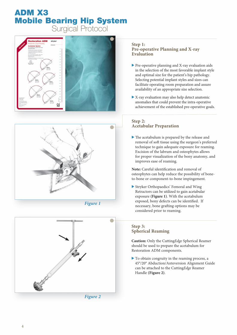
Figure 1
Figure 2
Step 1: Pre-operative Planning and X-ray Evaluation
> Pre-operative planning and X-ray evaluation aids in the selection of the most favorable implant style and optimal size for the patient’s hip pathology . Selecting potential implant styles and sizes can facilitate operating room preparation and assure availability of an appropriate size selection .
> X-ray evaluation may also help detect anatomic anomalies that could prevent the intra-operative achievement of the established pre-operative goals .
4
Step 3: Spherical Reaming
Caution: Only the CuttingEdge Spherical Reamer should be used to prepare the acetabulum for Restoration ADM components .
> To obtain congruity in the reaming process, a 45°/20° Abduction/Anteversion Alignment Guide can be attached to the CuttingEdge Reamer Handle (Figure 2) .
Step 2: Acetabular Preparation
> The acetabulum is prepared by the release and removal of soft tissue using the surgeon’s preferred technique to gain adequate exposure for reaming . Excision of the labrum and osteophytes allows for proper visualization of the bony anatomy, and improves ease of reaming .
Note: Careful identification and removal of osteophytes can help reduce the possibility of bone-to-bone or component-to-bone impingement .
> Stryker Orthopaedics’ Femoral and Wing Retractors can be utilized to gain acetabular exposure (Figure 1) . With the acetabulum exposed, bony defects can be identified . If necessary, bone grafting options may be considered prior to reaming .
ADM X3 Mobile Bearing Hip System Surgical Protocol
5
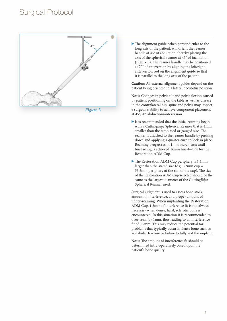
Figure 3
> The alignment guide, when perpendicular to the long axis of the patient, will orient the reamer handle at 45° of abduction, thereby placing the axis of the spherical reamer at 45° of inclination (Figure 3) . The reamer handle may be positioned at 20° of anteversion by aligning the left/right anteversion rod on the alignment guide so that it is parallel to the long axis of the patient .
Caution: All external alignment guides depend on the patient being oriented in a lateral decubitus position .
Note: Changes in pelvic tilt and pelvic flexion caused by patient positioning on the table as well as disease in the contralateral hip, spine and pelvis may impact a surgeon’s ability to achieve component placement at 45°/20° abduction/anteversion .
> It is recommended that the initial reaming begin with a CuttingEdge Spherical Reamer that is 4mm smaller than the templated or gauged size . The reamer is attached to the reamer handle by pushing down and applying a quarter-turn to lock in place . Reaming progresses in 1mm increments until final sizing is achieved . Ream line-to-line for the Restoration ADM Cup .
> The Restoration ADM Cup periphery is 1 .5mm larger than the stated size (e .g ., 52mm cup = 53 .5mm periphery at the rim of the cup) . The size of the Restoration ADM Cup selected should be the same as the largest diameter of the CuttingEdge Spherical Reamer used .
Surgical judgment is used to assess bone stock, amount of interference, and proper amount of under-reaming . When implanting the Restoration ADM Cup, 1 .5mm of interference fit is not always necessary when dense, hard, sclerotic bone is encountered . In this situation it is recommended to over-ream by 1mm, thus leading to an interference fit of 0 .5mm . This may reduce the potential for problems that typically occur in dense bone such as acetabular fracture or failure to fully seat the implant .
Note: The amount of interference fit should be determined intra-operatively based upon the patient’s bone quality .
45°
Surgical Protocol

Locking Sleeve
Figure 4
> The full profile of the CuttingEdge Spherical Reamer necessitates reaming to the full depth . The reamer head should be driven to the point where the rim/cross bar contacts the acetabular wall at the peripheral lunate region . Removal of the reamer from the handle is performed by pulling back on the locking sleeve and rotating the reamer head a quarter-turn in a clockwise direction (Figure 4) .
> Care should be taken so as not to enlarge or distort the acetabulum by eccentric reaming . Ream to the unicortical plate to medialize the cup . Ream to the full depth of the CuttingEdge Spherical Reamer to seat the reamer in the socket .
Note: Restoration ADM acetabular cups contain a 1 .5mm peripheral press-fit built into the cup as marked (e .g ., 52mm cup = 53 .5mm) .
Note: The CuttingEdge Spherical Reamers are very aggressive and perform best when sharp . Care should be taken to protect the reamer from unnecessary handling, as dull or damaged cutting teeth may cause improper reaming . Dull cutting teeth will deflect to cut softer bone and resist hard bone . This situation may result in an irregularly shaped or enlarged acetabulum preparation .
6
ADM X3 Mobile Bearing Hip System Surgical Protocol
Figure 5
Step 4: Trial Evaluation of the Restoration ADM Cup
> Following the reaming procedure, the appropriate Restoration ADM Window Trial of the same diameter as the last spherical reamer used, either left or right, is locked onto the Restoration ADM Trial Cup Holder . This is done by pulling the locking mechanism and releasing it after the window trial is set . The window trial is then placed in the acetabulum to evaluate the size and congruity of the preparation (Figure 5) . The trial is “windowed” for visualization and assessment of fit, contact and congruency of the trial within the acetabulum .
> The Restoration ADM Window Trial has an exact fit into the acetabulum (size for size), whereas the final implant has a press-fit of 1 .5mm .
Window Trial
Trial Cup Holder

Cup HolderRod
Cup HolderHandle
7
Figure 7
Important: The design of the cup enables it to anatomically fit into the shape of the natural acetabulum, preventing impingement with the iliopsoas tendon . The Restoration ADM Window Trial incorporates grooves that must be positioned in regard to the iliopsoas tendon . Once the window trial is set, it is recommended to make a mark on the acetabulum at the level of the superior reference mark (Figure 6) . This reference mark will provide a guideline for placing the final implant . The Restoration ADM implant should be positioned so that the superior mark on the cup is aligned with the mark on the acetabulum .
Note: A mark or series of marks can be made at the rim of the window trial to provide a depth reference for seating the implant .
Step 5: Restoration ADM Cup Implantation
> Assess acetabulum and surrounding soft tissue prior to cup introduction to ensure nothing is preventing cup implantation .
> Select the appropriately sized, left or right, Restoration ADM cup as clearly identified on the product label . Ensure the patient is in the correct position . At this step it is prudent to re-assess patient positioning in the surgical field .
> To facilitate the insertion of the cup, the Restoration ADM Cup Holder must be assembled as detailed below . For each cup diameter (46mm – 64mm) there is a corresponding expandable coupler .
Cup Impactor Assembly: First, insert the Cup Holder Rod into the proximal end of the Cup Holder Handle, snapping the two components together (Figure 7) . Then, assemble the Expandable Coupler, corresponding to the size of the cup to be implanted, onto the distal portion of the Cup Holder Rod (Figure 8) . Once the Expandable Coupler is placed onto the Cup Holder Rod, insert the wing nut through the top of the Expandable Coupler (Figure 9) . To engage the wing nut and to ensure that all components are securely assembled, turn the cup holder rod clockwise (holding it vertically) .
Figure 5
Expandable Coupler
Cup Holder Rod (Distal)
Cup HolderHandle
Figure 8
Psoas Parvus
Psoas Magnus
ADM X3System
IliopsoasValley
Window Trial
Window TrialReference Mark
Figure 6

8
Figure 9
Figure 10
Wing Nut
Expandable Coupler
Cup HolderHandle
Cup HolderRod
Gray Stripe
ImplantSuperiorPolarReference Mark
Gray Stripe
ExpandableCouplerReferenceMark
ADM X3 Mobile Bearing Hip System Surgical Protocol
Step 5: Restoration ADM Cup Implantation (Continued)
Note: When securing all components, be sure to only turn the Cup Holder Rod several turns–just enough to lock all components together . Turning the Cup Holder Rod too much or until tightened will expand the coupler prematurely, preventing it from properly fitting onto the implant when preparing for implantation .
Notice that the Expandable Coupler has a reference mark (that lines up with the axis of the handle) that corresponds to the superior reference mark on the implant . The gray stripes engraved on either side of the reference mark on the Expandable Coupler indicate the position of the cup notch (right or left) for the iliopsoas tendon (Figure 10) .
> While the implant is still in the packaging, place the Cup Holder vertically into it making certain to align the cup and the Expandable Coupler reference marks for proper Cup Holder/implant orientation and fit (Figure 10) . While maintaining the position of the cup, turn the Cup Holder handle to tighten the cup onto the end of the Cup Holder and prepare it for placement into the acetabulum .
Note: The Expandable Coupler must be fully seated within the implant before tightening . Fully seating the Expandable Coupler can be achieved by pressing it vertically into the cup, while placed on a table . When fully seated, begin tightening the Expandable Coupler onto the cup for a secure fit . Following these instructions will help reduce the risk of the cup and Expandable Coupler/Cup Holder from disengaging during impaction .
> Cup Placement: Locate the reference mark made previously on the acetabulum . Position the cup according to the preset reference mark . Positioning the cup according to the preset reference mark will ensure proper anatomic cup placement . Impact the cup into the acetabulum with the slotted mallet (1120-1000) (Figure 11) . Once the cup is securely impacted, remove the cup holder from the cup by turning the cup holder rod counter-clockwise and pulling the cup holder backwards with minimal force .
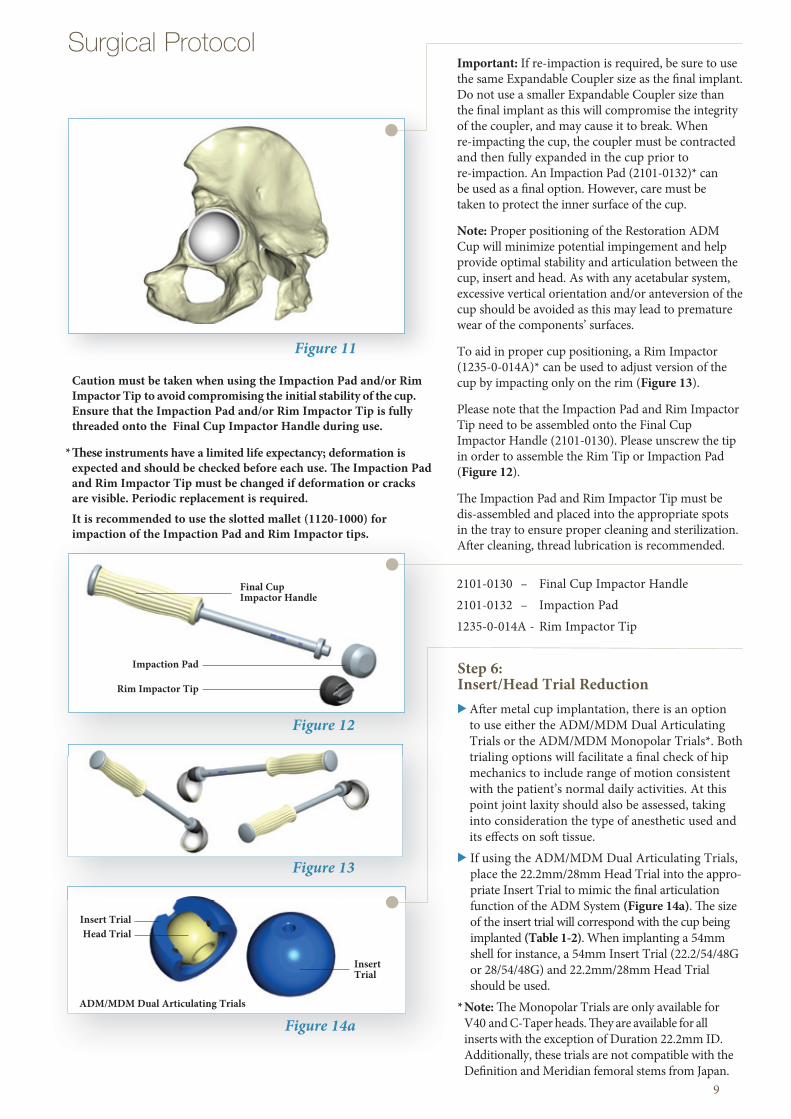
Figure 14a
Insert TrialHead Trial
Insert Trial
ADM/MDM Dual Articulating Trials
Figure 12
Figure 13
Impaction Pad
Rim Impactor Tip
Final CupImpactor Handle
9
Surgical Protocol Important: If re-impaction is required, be sure to use the same Expandable Coupler size as the fi nal implant . Do not use a smaller Expandable Coupler size than the fi nal implant as this will compromise the integrity of the coupler, and may cause it to break . When re-impacting the cup, the coupler must be contracted and then fully expanded in the cup prior to re-impaction . An Impaction Pad (2101-0132)* can be used as a fi nal option . However, care must be taken to protect the inner surface of the cup .
Note: Proper positioning of the Restoration ADM Cup will minimize potential impingement and help provide optimal stability and articulation between the cup, insert and head . As with any acetabular system, excessive vertical orientation and/or anteversion of the cup should be avoided as this may lead to premature wear of the components’ surfaces .
To aid in proper cup positioning, a Rim Impactor (1235-0-014A)* can be used to adjust version of the cup by impacting only on the rim (Figure 13) .
Please note that the Impaction Pad and Rim Impactor Tip need to be assembled onto the Final Cup Impactor Handle (2101-0130) . Please unscrew the tip in order to assemble the Rim Tip or Impaction Pad (Figure 12) .
Th e Impaction Pad and Rim Impactor Tip must be dis-assembled and placed into the appropriate spots in the tray to ensure proper cleaning and sterilization . Aft er cleaning, thread lubrication is recommended .
Figure 11
Step 6: Insert/Head Trial Reduction> Aft er metal cup implantation, there is an option
to use either the ADM/MDM Dual Articulating Trials or the ADM/MDM Monopolar Trials* . Both trialing options will facilitate a fi nal check of hip mechanics to include range of motion consistent with the patient’s normal daily activities . At this point joint laxity should also be assessed, taking into consideration the type of anesthetic used and its eff ects on soft tissue .
> If using the ADM/MDM Dual Articulating Trials, place the 22 .2mm/28mm Head Trial into the appro-priate Insert Trial to mimic the fi nal articulation function of the ADM System (Figure 14a) . Th e size of the insert trial will correspond with the cup being implanted (Table 1-2) . When implanting a 54mm shell for instance, a 54mm Insert Trial (22 .2/54/48G or 28/54/48G) and 22 .2mm/28mm Head Trial should be used .
* Note: Th e Monopolar Trials are only available for V40 and C-Taper heads . Th ey are available for all inserts with the exception of Duration 22 .2mm ID . Additionally, these trials are not compatible with the Defi nition and Meridian femoral stems from Japan .
2101-0130 – Final Cup Impactor Handle2101-0132 – Impaction Pad1235-0-014A - Rim Impactor Tip
Caution must be taken when using the Impaction Pad and/or Rim Impactor Tip to avoid compromising the initial stability of the cup . Ensure that the Impaction Pad and/or Rim Impactor Tip is fully threaded onto the Final Cup Impactor Handle during use .
* Th ese instruments have a limited life expectancy; deformation is expected and should be checked before each use . Th e Impaction Pad and Rim Impactor Tip must be changed if deformation or cracks are visible . Periodic replacement is required .
It is recommended to use the slotted mallet (1120-1000) for impaction of the Impaction Pad and Rim Impactor tips .

10
Step 6: Insert/Head Trial Reduction (Continued)
> If using the ADM/MDM Monopolar Trials, choose the Trial Sleeve that corresponds to the desired femoral head taper and offset and assemble it into the appropriate Insert Trial by firmly pushing the sleeve into the inner geometry of the Insert Trial (Figure 14b, Tables 1, 3-4) . Correct assembly of the Trial Sleeve and Insert Trials will produce an audible click . The size of the Insert Trial will correspond with the cup being implanted (Table 1) .
> Place the assembled Dual Articulating or Monopolar Trials onto the neck trial or stem trunnion component . Ensure that the Monopolar Trials are locked by firmly pushing the Insert Trial Sleeve assembly onto the neck trial or stem . Reduce the hip, checking for hip stability and the restoration of leg length . Fine tuning of hip joint mechanics may be achieved with the use of different +/- offsets .
Figure 14b
Insert Trial
ADM ShellOuter Diameter
Trial Sleeve
MDM CoCrLiner Size
Inner Diameter of the Corresponding ADM/MDM Insert
Note: Inserts are compatible with Stryker 28mm heads only .
Table 1: ADM Shell, X3 and Duration Inserts (28mm) and Femoral Head Compatibility
1235-2-462 1235-2-461 1236-2-846 – 1235-0-846 28mm 1235-0-846M1235-2-482 1235-2-481 1236-2-848 1235-2-848 1235-0-848 28mm 1235-0-848M1235-2-502 1235-2-501 1236-2-850 1235-2-850 1235-0-850 28mm 1235-0-850M1235-2-522 1235-2-521 1236-2-852 1235-2-852 1235-0-852 28mm 1235-0-852M1235-2-542 1235-2-541 1236-2-854 1235-2-854 1235-0-854 28mm 1235-0-854M1235-2-562 1235-2-561 1236-2-856 1235-2-856 1235-0-856 28mm 1235-0-856M1235-2-582 1235-2-581 1236-2-858 1235-2-858 1235-0-858 28mm 1235-0-858M1235-2-602 1235-2-601 1236-2-860 1235-2-860 1235-0-860 28mm 1235-0-860M1235-2-622 1235-2-621 1236-2-862 1235-2-862 1235-0-862 28mm 1235-0-862M1235-2-642 1235-2-641 1236-2-864 1235-2-864 1235-0-864 28mm 1235-0-864M
ADM Shell ADM Shell ADM/MDM ADM/MDM ADM/MDM Required ADM/MDM Left Right X3 Insert Duration Dual Femoral Monopolar (28mm ID) Insert Articulating Head Size Insert Trial (28mm ID) Insert Trial (mm) (28mm ID)
ADM X3 Mobile Bearing Hip System Surgical Protocol
Note: With the launch of the monopolar trials, all trays moving forward will have the same catalog number (1235-0-300) along with updated markings to provide guidance on the monopolar trial placement . You will be able to distinguish between an original tray and a new tray as the original will not specify ‘sleeves’ on the lid .
If a tray is being used that was launched prior to the monopolar trials, the following guidelines must be followed:• The new monopolar insert trials (1235-0-8XXM) fit
in the same location as the dual articulating trial inserts (1235-0-8XX) . The new monopolar sleeve trials (1235-V-XXXX and 1235-C-XXXX) fit in the same area marked for the head supporting piece (1235-0-009) .
Part NumberADM/MDM Monopolar Trials
Note: The Monopolar Trials are marked ‘trial do not implant’ . If there is any reason to believe that the trial has been accidentally implanted, the Monopolar Insert Trial is radiopaque and would be visible on an X-Ray .

11
Surgical Protocol
Figure 14c
> Once hip stability and leg length have been checked, the Dual Articulating or Monopolar Trial assembly can be removed from the neck trial or trunnion as one unit . If using the Monopolar Trials, the Trial Sleeve can then be removed from the Insert Trial with the assistance of standard Kocher forceps by squeezing the Trial Sleeve and pulling it out of the Insert Trial (Figure 14c) . This can also be accomplished by hand .
Note: When using dual mobility implants, impingement should be carefully assessed and avoided during range of motion . Impingement can result in increased wear in metal polyethylene systems .
Tips: Paul Perona, M .D .
When using the ADM/MDM Dual Articulating Trials, place the 22 .2mm or 28mm trial head onto the neck trial or stem trunnion and place the ADM/MDM Insert Trial into the cup . The smaller trial head can then be reduced into the Insert Trial for ease of reduction .
Position of Kocher Forceps for Sleeve Removal
Table 3: Monopolar Trial Sleeve Catalog Numbers and V40 28mm Femoral Head Options
-4mm 1235-V-0040 � �-2 .7mm 1235-V-0027 � �-2 .5mm 1235-V-0025 �+0mm 1235-V-1000 � � � �+4mm 1235-V-1040 � � � �+6mm 1235-V-1060 �+8mm 1235-V-1080 �
+12mm 1235-V-1120 �
V40 28mm Monopolar LFIT CoCr BIOLOX BIOLOX Alumina Femoral Trial Sleeve delta delta Head Offsets Universal
Table 4: Monopolar Trial Sleeve Catalog Numbers and C-Taper 28mm Femoral Head Options
-3mm 1235-C-0030 �-2 .5mm 1235-C-0025 � � �+0mm 1235-C-1000 � � � �
+2 .5mm 1235-C-1025 � � �+5mm 1235-C-1050 � � � �
+7 .5mm 1235-C-1075 �+10mm 1235-C-1100 �
C-Taper 28mm Monopolar LFIT CoCr BIOLOX BIOLOX Alumina Femoral Trial Sleeve delta delta Head Offsets Universal
Table 2: ADM Shell, Duration Insert (22 .2mm) and Femoral Head Compatibility ADM Shell ADM Shell ADM/MDM ADM/MDM Dual Required Left Right Duration Insert Articulating Insert Femoral Head (22 .2mm ID) Trial (22 .2mm ID) Size (mm)
Note: Inserts are compatible with Stryker 22 .2mm heads only .
1235-2-462 1235-2-461 1235-2-246 1235-0-246 22 .2mm
1235-2-482 1235-2-481 1235-2-248 1235-0-248 22 .2mm
1235-2-502 1235-2-501 1235-2-250 1235-0-250 22 .2mm
1235-2-522 1235-2-521 1235-2-252 1235-0-252 22 .2mm
1235-2-542 1235-2-541 1235-2-254 1235-0-254 22 .2mm
1235-2-562 1235-2-561 1235-2-256 1235-0-256 22 .2mm1235-2-582 1235-2-581 1235-2-258 1235-0-258 22 .2mm
1235-2-602 1235-2-601 1235-2-260 1235-0-260 22 .2mm
1235-2-622 1235-2-621 1235-2-262 1235-0-262 22 .2mm
1235-2-642 1235-2-641 1235-2-264 1235-0-264 22 .2mm

12
ADM X3 Mobile Bearing Hip System Surgical Protocol
Figure 15
Figure 16
Step 8: Reduction and Closure
> Once the Insert and Head are assembled, the unit is ready for implantation and reduction .
> Place insert/head unit onto the trunnion of the femoral stem and slightly impact with insert reduction tool .
> Then, by exerting axial traction on the limb and pressure on the insert using the insert reduction tool (Figure 16), reduce the hip and check for laxity and range of motion . The surgical site is then closed according to surgeon preference .
Step 7: Insert/Head Implantation
Back table assembly of the Insert and corresponding V40 or C-Taper, 22 .2mm or 28mm Head is required . (Figure 15)
The following instructions must be carefully adhered to:
> Place the Press Stand flat on the table and place the Press onto the Press Stand Pin .
> Put the Femoral Head Supporting Piece into the base of the Press .
> Open the press by turning the T-handle counter-clockwise until the polyethylene insert fits above the femoral head and below the plastic cone portion of the press .
> Place the Femoral Head onto the Head Supporting Piece, and then place Insert onto the Femoral Head .
> Once the Femoral Head and polyethylene insert are in a vertical position, tighten the Press until the head is fully lodged into the insert . After insertion, the air confined between the head and insert is usually released, resulting in a characteristic noise .
> After the head and insert are assembled, verify that the coupling has complete mobility .
Press Stand
Press
Head Supporting Piece
Insert Reduction Tool
Note: Ensure that the inside of the shell is clean and free of soft tissue or other debris, which could prevent the insert from properly seating in the shell .
Warning: A metal or ceramic head should not be used in place of the dual mobility insert/head . The Restoration ADM cup is not intended for use as a metal-on-metal or ceramic-on-metal articulation . No testing has been conduct-ed to determine that these bearing couples produce favor-able mechanical outcomes .
Only Stryker 22 .2mm or 28mm femoral heads should be inserted into the ADM polyethylene inserts .
13
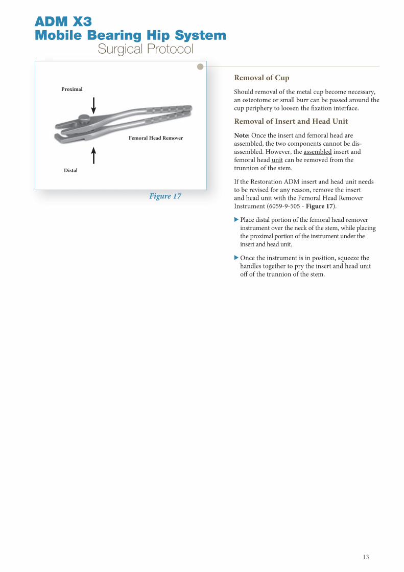
Removal of Cup
Should removal of the metal cup become necessary, an osteotome or small burr can be passed around the cup periphery to loosen the fi xation interface .
Removal of Insert and Head Unit
Note: Once the insert and femoral head are assembled, the two components cannot be dis-assembled . However, the assembled insert and femoral head unit can be removed from the trunnion of the stem .
If the Restoration ADM insert and head unit needs to be revised for any reason, remove the insert and head unit with the Femoral Head Remover Instrument (6059-9-505 - Figure 17) .
> Place distal portion of the femoral head remover instrument over the neck of the stem, while placing the proximal portion of the instrument under the insert and head unit .
> Once the instrument is in position, squeeze the handles together to pry the insert and head unit off of the trunnion of the stem .
Figure 17
ADM X3Mobile Bearing Hip System Surgical Protocol
Proximal
Distal
Femoral Head Remover

14

15
Catalog Information
16
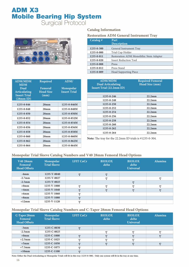
Catalog Information Restoration ADM General Instrument Tray
ADM X3 Mobile Bearing Hip System Surgical Protocol
1235-0-300 General Instrument Tray1235-0-000 Trial Cup Holder1235-0-011 Restoration ADM Monolithic Stem Adapter1235-0-020 Insert Reduction Tool1235-0-008 Press1235-0-012 Press Stand1235-0-009 Head Supporting Piece
Catalog # Part Description
1235-0-846 28mm 1235-0-846M1235-0-848 28mm 1235-0-848M1235-0-850 28mm 1235-0-850M1235-0-852 28mm 1235-0-852M1235-0-854 28mm 1235-0-854M1235-0-856 28mm 1235-0-856M1235-0-858 28mm 1235-0-858M1235-0-860 28mm 1235-0-860M1235-0-862 28mm 1235-0-862M1235-0-864 28mm 1235-0-864M
ADM/MDM Required ADM/ MDM Dual Femoral Monopolar Articulating Head Size Insert Trial Insert Trial (mm) (28mm ID)
1235-0-246 22 .2mm1235-0-248 22 .2mm1235-0-250 22 .2mm1235-0-252 22 .2mm1235-0-254 22 .2mm1235-0-256 22 .2mm1235-0-258 22 .2mm1235-0-260 22 .2mm1235-0-262 22 .2mm1235-0-264 22 .2mm
ADM/MDM Required Femoral Dual Articulating Head Size (mm) Insert Trial (22 .2mm ID)
Note: The tray for the 22 .2mm ID trials is #1235-0-304 .
Monopolar Trial Sleeve Catalog Numbers and V40 28mm Femoral Head Options
Monopolar Trial Sleeve Catalog Numbers and C-Taper 28mm Femoral Head Options
Note: Either the Dual Articulating or Monopolar Trials will fit in this tray (1235-0-300) . Only one system will fit in the tray at one time .
-4mm 1235-V-0040 � �-2 .7mm 1235-V-0027 � �-2 .5mm 1235-V-0025 �+0mm 1235-V-1000 � � � �+4mm 1235-V-1040 � � � �+6mm 1235-V-1060 �+8mm 1235-V-1080 �
+12mm 1235-V-1120 �
V40 28mm Monopolar LFIT CoCr BIOLOX BIOLOX Alumina Femoral Trial Sleeve delta delta Head Offsets Universal
-3mm 1235-C-0030 �-2 .5mm 1235-C-0025 � � �+0mm 1235-C-1000 � � � �
+2 .5mm 1235-C-1025 � � �+5mm 1235-C-1050 � � � �
+7 .5mm 1235-C-1075 �+10mm 1235-C-1100 �
C-Taper 28mm Monopolar LFIT CoCr BIOLOX BIOLOX Alumina Femoral Trial Sleeve delta delta Head Offsets Universal

17
1235-0-302 Restoration ADM Left Cup Instrument Tray
1235-0-462 Restoration ADM Window Trial Left 46mm
1235-0-482 Restoration ADM Window Trial Left 48mm
1235-0-502 Restoration ADM Window Trial Left 50mm
1235-0-522 Restoration ADM Window Trial Left 52mm
1235-0-542 Restoration ADM Window Trial Left 54mm
1235-0-562 Restoration ADM Window Trial Left 56mm
1235-0-582 Restoration ADM Window Trial Left 58mm
1235-0-602 Restoration ADM Window Trial Left 60mm
1235-0-622 Restoration ADM Window Trial Left 62mm
1235-0-642 Restoration ADM Window Trial Left 64mm
Restoration ADM Left Instrument Tray Catalog # Part Description
Surgical Protocol
Restoration ADM Right Instrument Tray Catalog # Part Description
1235-0-301 Restoration ADM Right Cup Instrument Tray
1235-0-461 Restoration ADM Window Trial Right 46mm
1235-0-481 Restoration ADM Window Trial Right 48mm
1235-0-501 Restoration ADM Window Trial Right 50mm
1235-0-521 Restoration ADM Window Trial Right 52mm
1235-0-541 Restoration ADM Window Trial Right 54mm
1235-0-561 Restoration ADM Window Trial Right 56mm
1235-0-581 Restoration ADM Window Trial Right 58mm
1235-0-601 Restoration ADM Window Trial Right 60mm
1235-0-621 Restoration ADM Window Trial Right 62mm
1235-0-641 Restoration ADM Window Trial Right 64mm

ADM X3Mobile Bearing Hip™ System Surgical Protocol
18
Catalog # Part Description
1235-0-303A* Impaction Set Tray1235-0-305A* Restoration ADM Additional Fixture for Impaction Set Tray1235-4-465 46mm Expandable Coupler1235-4-485 48mm Expandable Coupler1235-4-505 50mm Expandable Coupler1235-4-525 52mm Expandable Coupler1235-4-545 54mm Expandable Coupler1235-4-565 56mm Expandable Coupler1235-4-585 58mm Expandable Coupler1235-4-605 60mm Expandable Coupler1235-4-625 62mm Expandable Coupler1235-4-645 64mm Expandable Coupler1235-0-003 Straight Cup Holder Handle1235-0-006A Nut For Straight Cup Holder1235-0-007 Rod For Straight Cup Holder
Catalog InformationRestoration ADM Impaction Instrument Tray
CuttingEdge Acetabular Reamers(Must be used to implant Restoration ADM)
Catalog # Part Description
2402-0007 Acetabular Reamer Tray 2402-0090 Acetabular Reamer Tray Lid2102-0444 44mm Acetabular Reamer2102-0445 45mm Acetabular Reamer2102-0446 46mm Acetabular Reamer2102-0447 47mm Acetabular Reamer2102-0448 48mm Acetabular Reamer 2102-0449 49mm Acetabular Reamer2102-0450 50mm Acetabular Reamer 2102-0451 51mm Acetabular Reamer 2102-0452 52mm Acetabular Reamer2102-0453 53mm Acetabular Reamer2102-0454 54mm Acetabular Reamer 2102-0455 55mm Acetabular Reamer 2102-0456 56mm Acetabular Reamer 2102-0457 57mm Acetabular Reamer2102-0458 58mm Acetabular Reamer2102-0459 59mm Acetabular Reamer2102-0460 60mm Acetabular Reamer2102-0461 61mm Acetabular Reamer2102-0462 62mm Acetabular Reamer2102-0463 63mm Acetabular Reamer2102-0464 64mm Acetabular Reamer2102-0465 65mm Acetabular Reamer
2101-0130 Final Cup Impactor Handle
2101-0132 Impaction Pad
1235-0014A Rim Impactor Tip
Optional Instruments Catalog # Part Description
* Please note that the Impaction Pad and Rim Impactor Tip need to be assembled onto the Final Cup Impactor Handle (2010-0130) .
* Please note that the Impaction Set Tray (1235-0-303A) has space for an additional tray (1235-0-305A) to hold the Final Cup Impactor Handle along with the Impaction Pad and Rim Impactor Tip .
1235-0-303A
1235-0-305A*

19
Surgical Protocol
Restoration ADM Cup Implants Catalog # Part Description
1235-2-461 Restoration ADM Cup Right 46mm1235-2-481 Restoration ADM Cup Right 48mm1235-2-501 Restoration ADM Cup Right 50mm1235-2-521 Restoration ADM Cup Right 52mm1235-2-541 Restoration ADM Cup Right 54mm1235-2-561 Restoration ADM Cup Right 56mm1235-2-581 Restoration ADM Cup Right 58mm1235-2-601 Restoration ADM Cup Right 60mm1235-2-621 Restoration ADM Cup Right 62mm1235-2-641 Restoration ADM Cup Right 64mm
Catalog # Part Description
1235-2-462 Restoration ADM Cup Left 46mm1235-2-482 Restoration ADM Cup Left 48mm1235-2-502 Restoration ADM Cup Left 50mm1235-2-522 Restoration ADM Cup Left 52mm1235-2-542 Restoration ADM Cup Left 54mm1235-2-562 Restoration ADM Cup Left 56mm1235-2-582 Restoration ADM Cup Left 58mm1235-2-602 Restoration ADM Cup Left 60mm1235-2-622 Restoration ADM Cup Left 62mm1235-2-642 Restoration ADM Cup Left 64mm
X-Ray Templates
1235-0-200 Restoration ADM X-ray Template Scale 11235-0-215 Restoration ADM X-ray Template Scale 1 .15
Catalog # Part Description
Important: The Restoration ADM cup is intended for use with the Restoration ADM insert only . It is not intended for use with Stryker LFIT Anatomic CoCr heads .

Notes

Notes

A surgeon must always rely on his or her own professional clinical judgment when deciding whether to use a particular product when treating a particular patient . Stryker does not dispense medical advice and recommends that surgeons be trained in the use of any particular product before using it in surgery .
The information presented is intended to demonstrate the breadth of Stryker product offerings . A surgeon must always refer to the package insert, product label and/or instructions for use before using any Stryker product . The products depicted are CE marked according to the Medical Device Directive 93/42/EEC .
Products may not be available in all markets because product availability is subject to the regulatory and/or medical practices in individual markets . Please contact your Stryker representative if you have questions about the availability of Stryker products in your area .
Stryker Corporation or its divisions or other corporate affiliated entities own, use or have applied for the following trademarks or service marks: ADM, CuttingEdge, LFIT, MDM, Mobile Bearing Hip, PSL, Restoration, Stryker, Stryker Orthopaedics, V40, X3 . All other trademarks are trademarks of their respective owners or holders .
BIOLOX delta is a registered trademark of Ceramtec Ag .
ADMX3-SP-1 Copyright © 2015 Stryker
www .stryker .com