administrators guide:wyse device managertm · understanding the show empty custom group folders...
TRANSCRIPT

Administrators GuideWyse Device Manager™ Release 4.9
Issue: 021512PN: 883885-01 Rev. M

Copyright Notices© 2012, Wyse Technology Inc. All rights reserved.
This manual and the software and firmware described in it are copyrighted. You may not reproduce, transmit, transcribe, store in a retrieval system, or translate into any language or computer language, in any form or by any means, electronic, mechanical, magnetic, optical, chemical, manual or otherwise, any part of this publication without express written permission.
End User License Agreement (“License”)A copy of the Wyse Technology End User License Agreement is included in the software and provided for your reference only. The License at http://www.wyse.com/license as of the purchase date is the controlling licensing agreement. By copying, using, or installing the software or the product, you agree to be bound by those terms.
TrademarksThe Wyse and PocketCloud logos and Wyse and PocketCloud are trademarks of Wyse Technology Inc. Other product names mentioned herein are for identification purposes only and may be trademarks and/or registered trademarks of their respective companies. Specifications subject to change without notice.
Restricted Rights LegendYou acknowledge that the Software is of U.S. origin. You agree to comply with all applicable international and national laws that apply to the Software, including the U.S. Export Administration Regulations, as well as end-user, end-use and country destination restrictions issued by U.S. and other governments. For additional information on exporting the Software, see http://www.microsoft.com/exporting.
Ordering InformationFor availability, pricing, and ordering information in the United States and Canada, call 1-800-GET-WYSE (1-800-438-9973) or visit us at http://www.wyse.com. In all other countries, contact your sales representative.

Contents
1 Introduction 1About this Guide 2
Finding the Information You Need in this Guide 2Wyse Technical Support 2
Related Documentation and Services 2Wyse Online Community 2
2 Getting Started 3Getting to Know the Administrator Console 3
Using Right-Click Menus 4About WDM Wizards 6Using WDM Toolbar Icons 7
Device Manager Icons 7Package Manager Icons 8Update Manager Icons 8Report Manager Icons 8Configuration Manager Icons 8
Understanding Your WDM Licensing 9Knowing Your WDM Version 9Some Important Initial Considerations 10
3 Device Manager 11Managing Devices 11
Creating a Device Filter 15Editing a Device Filter 15Deleting a Device Filter 15Searching for a Device with Find Device in View and Quick Find 16
Using Find Device in View 16Using Quick Find 17
Viewing Device Details 19Adding Devices 22
Adding Devices Using Dynamic Discovery 23Adding Devices Manually 24
Changing Device Properties 25Changing Basic Device Information 25Changing Network Properties 26Actions Supported by WDM for ThreadX Devices 27
Remotely Shadowing Devices 29Creating and Viewing Log Files 30Using the Package Distribution Wizard to Schedule a Package for Distribution 31Using the Remote Task Manager to View Applications, Processes, and Performance for a Device 33

iv Contents
4 Package Manager 35Managing WDM Packages 35
Register a Package from a Script File (.RSP) 39Register an Image from a Device (Requires PXE) 40Register a Configuration from a Device 41
Registering a Configuration from Wyse Devices Running Wyse Enhanced SUSE Linux Enterprise or Linux v6.x 41Registering a Configuration from Wyse Devices Running Windows CE 42
Build and Register a CE Image Plus Add-ons (CE Bundled Image) 44Building and Registering a ThreadX Package 46Registering an Image from a Device Using WISard 47
Registering an Image from a Device Using WISard: Initial Setup and Use 47Registering an Image from a Device Using WISard: After Initial Setup 49
Registering an Image from a Device Using Merlin 50Registering an Image from a Device Using Merlin: Initial Setup and Use 50Registering an Image from a Device Using Merlin: After Initial Setup 52
Viewing the Details of a Registered WDM Package 54Viewing and Changing the Script of a Registered WDM Package 55Exporting the Script of a Registered WDM Package 56
5 Update Manager 57Managing the Schedules for Device Updates 57
Scheduling Device Updates Using the Package Distribution Wizard 61Scheduling Device Updates Using the Drag-and-Drop Method 63Scheduling Device Updates Using the Automatic Distribution Method (Assigning a Default Device Configuration) 64Changing a Scheduled Device Update for a WDM Package 64
WDM Enterprise Edition Only: Scheduling a Remote Repository Synchronization 66Configuring an Automatic Synchronization 66Manually Scheduling a Synchronization (Using the Remote Software Repository Synchronization Wizard) 67
WDM Enterprise Edition Only: Changing a Remote Software Repository Synchronization 69
6 Report Manager 71Creating and Managing Reports 71
Log Reports 74Device Listings 75Package Distribution Reports 76Client Package Reports 77Installed Software Reports 78Client Down Time Reports 80Installation Details Report 81Component Details Report 82Package Synchronization Reports 83
Package Synchronization History Reports 84Unsynchronized Packages Reports 85Orphaned Package Reports 86
7 Configuration Manager 87Managing WDM Configuration Settings and Preferences 87Managing Group Types 88
Creating Custom Group Types 88Editing Custom Group Types 88Deleting Custom Group Types 88

Contents v
Managing Views 89Creating Views 89Editing Views 90Deleting Views 90Using Advanced View Configuration Options 91
Managing Default Device Configurations 92Creating and Assigning Default Device Configurations 92Editing Default Device Configurations 95Deleting Default Device Configurations 95Viewing the Summary of a Default Device Configuration 95
Managing Licenses and Certificates 97Managing WDM Sales Keys 97
Viewing Sales Key Details 97Adding Sales Keys 97Upgrading to an Enterprise Sales Key 98Deleting WDM Sales Keys 98
Configuring Preferences 99Device Manager Preferences 99Logging Preferences 101Service Preferences 103DHCP/TFTP Preferences 106Scheduling Preferences 107Subnet Preferences 109Wyse Thin OS Preferences 110
Understanding WDM Repositories 111WDM Enterprise Edition Only: Managing Software Repositories 111Registering Remote Software Repositories 112Editing Software Repositories 114Deleting Software Repositories 114
Managing Networks 115Managing Subnets 115
Adding Subnets to WDM Manually 115Editing Subnets 116Deleting Subnets 116
Managing IP Ranges 117Adding IP Ranges to WDM Manually 117Editing IP Ranges 118Deleting IP Ranges 118
Managing User Permissions 119Adding Users from Local Computer Accounts 119Adding Users and Groups from Active Directory 120Editing User Permissions 121Deleting Users 121
Using WDM Utilities 122Importing IP Range Data from Files 122
Required Format for Importing IP Range Data from Files 123Importing Subnet Data from Files 123
Required Format for Importing Subnet Data from Files 124Importing Software Repository Data 125
Required Format for Importing Software Repository Data from Files 126Importing Device Settings Data from Files 127
Required Format for Importing Device Settings from Files 127Generating Diagnostic Reports 128Using the Certificate Expiration Tracker 129
Viewing Certificate Information in the Certificate Expiration Tracker 129Adding a Certificate to the Expiration Tracker 130Editing a Certificate in the Expiration Tracker 130

vi Contents
A Licensing and Sales Keys 131About WDM Sales Key Activation 131
WDM Workgroup Edition 131WDM Enterprise Edition 131
Activating Your Sales Key 132
B Working with Groups and Views 135Understanding Groups Types and Views 135Understanding the Show Empty Custom Group Folders Option 136Assigning Devices to Groups 137Moving Devices Across Custom Groups 138Creating Views: A Working Example 139
C Upgrading WDM Agents 141Using the Auto-Agent Upgrade Feature 141Upgrading Older WDM Agents Selectively 143Understanding WDM Agent Error Codes 144
File Transfer Protocol (FTP) Error Codes 144Windows Sockets Error Codes 147
D About WDM Security 149Importing Certificates on Devices 149Using Secure Communication (HTTPS) 153
HTTPS Communication Initiated by HAgent 153HTTPS Communication Initiated by the WDM Administrator Console 154
Determining the Port Number 154Determining the Protocol 154
E WDM ScriptBuilder Tool and Scripting Language 157Using WDM Scripting Language 157Using the WDM ScriptBuilder Tool 158
Creating a New WDM Script Package 158Editing a New WDM Script Package 159Reviewing a New WDM Script Package 159
Understanding the WDM Package Structure 159Optional Arguments and HKEY_CURRENT_USER 160Understanding the Script File Structure 160Version 162
BootFloppy= 162Category= 162Command= 162DeployedSW= 162Description= 162Image= 162ImageSize= 163Number= 163OS= 163Use_PXE= 163Use_Remote= 163
Script 164Append File 164Confirm Disk Free Space 164Confirm File Version 165Confirm Image 166Confirm Minimum RAM Size 166

Contents vii
Confirm Operating System 167Confirm User 168Delete File 168Delete Registry Branch 169Delete Registry Value 169Delete Tree 170End Lockout 170Execute on Device 171Get File 172Get Registry 172Get Registry Value 173Local Pause 174Lockout User 174Merge Registry 175Query User 176Reboot 177Send File 177Set Device Information 178Set Network Information 179Set Profile 181Set Registry Value 182Shutdown 183Synch Time 184Wake On LAN 185X Copy 185
F WDM Mass Imaging Tool and Device Imaging 187Using the WDM Mass Imaging Tool 187
Prerequisites 187Procedures 188
Using Device Imaging in WDM 189PXE Based Imaging 189
PXE Request Routing 189Installing and Configuring DHCP 189Deploying an Image Package 190About the Imaging Process 191
Non-PXE Based Imaging (Wyse ThinOS Boot Agent) 192Configuring the WDM URLs from the Wyse ThinOS Boot Agent Desktop 192Configuring the DHCP Server 193Configuring Service Location Records in the DNS Server 197Configuring a WDM Server Host Name in the DNS Server 199Deploying the Image Using Merlin in Non-PXE Based imaging 200
Non-PXE Based Imaging (Merlin Boot Agent) 201Raw Imaging for SUSE Linux: How to Register a SUSE Linux Raw Image in WDM 202
G Autogenic Imaging 203Quick Overview: What You Will Do 203Detailed Procedures 204
Case 1: Performing the Downloading and Imaging Processes Separately 207Case 2: Performing the Downloading and Imaging Processes Together 209
Autogenic Imaging Technical Details 209Update Manager (Autogenic Imaging Technical Details) 209WDM (Autogenic Imaging Technical Details) 210

viii Contents
H Troubleshooting 211WDM Installation Failure 212Problem with WDM Upgrade Installation 212Default Device Configurations not Working Properly with Wyse® WintermTM 1 series Thin Clients 213Remote Shadowing Problems 213Setting the Correct Logging Levels 213
Viewing Service Logs—Example 213Changing the IP Address of the WDM Server 214Problems with Repository Test Connection in IIS 6.0 215Problems with Attaching Database 215Problems with Discovering Devices 216Problems with Discovering PXE Devices 216Package Errors 216Problem With HServer Init Requests in IIS 6.0 216Wake on LAN Command Does Not Reach Remote Devices 218Problem in Repository Installation in IIS 7.0 in HTTP Mode 218Problem with Merlin Imaging in Windows Server 2008 219Recovering Dead Devices 219Converting a WISard Image to Merlin 220Error Messages after Uninstalling WDM 221
Tables 223

1 Introduction
Wyse Device ManagerTM (WDM) software is the premier enterprise solution for managing network intelligent devices simply, remotely, and securely. It enables IT professionals to easily organize, upgrade, control, and support thousands of devices running Microsoft Windows XP Embedded, Microsoft Windows CE, Wyse Enhanced Microsoft Windows Embedded Standard 2009, Wyse Enhanced Microsoft Windows Embedded Standard 7, Wyse Enhanced SUSE Linux Enterprise, Wyse ThinOS, Wyse Xenith, or ThreadX across any LAN, WAN, or wireless network.
WDM software uses industry standard communication protocols and a component-based architecture to efficiently manage your network devices. Its intuitive, simple, and powerful user interface is built to operate as a standard snap-in to the Microsoft Management Console (MMC). From one simple to use console, WDM allows you to manage all of your network devices easily and quickly.

2 Chapter 1
About this GuideThis guide is intended for administrators of the WDM system. It provides information and detailed system configurations to help you design and manage a WDM environment. Depending on the installation of WDM you are running (WDM Workgroup Edition or WDM Enterprise Edition), some sections of the guide may not be relevant to you and are marked as such (for example, WDM Enterprise Edition Only).
This guide is intended for experienced network administrators and Information Technology professionals who have installed and configured Windows operating systems and applications.
Finding the Information You Need in this GuideYou can use either the Search window or Find toolbar to locate a word, series of words, or partial word in an active PDF document. For detailed information on using these features, refer to the Help in your PDF reader.
Wyse Technical SupportTo access Wyse technical resources, visit http://www.wyse.com/support. If you still have questions, you can submit your questions using the Wyse Self-Service Center athttp://support.wyse.com/selfservice.html or call Customer Support at 1-800-800-WYSE (toll free in U.S. and Canada). Hours of operation are from 6:00 A.M. to 5:00 P.M. Pacific Time, Monday through Friday.
To access international support, visit http://www.wyse.com/global.
Related Documentation and ServicesWyse Device Manager features can found in the Wyse Device Manager Datasheet. It is available on the Wyse Web site at:http://www.wyse.com/products/software/devicemanager/index.asp.
Installation Guide: Wyse Device ManagerTM provides the step-by-step instructions you need to install and configure a WDM environment. It also includes the requirements you must address before you begin the installation procedures.
Wyse Cloud Software is available on the Wyse Web site at:http://www.wyse.com/products/software.
Wyse Online CommunityWyse maintains an online community where users of our products can seek and exchange information on user forums. Visit the Wyse Online Community forums at:http://community.wyse.com/forum.

2 Getting Started
This chapter provides a brief overview of the functional areas within the WDM Administrator Console. It also provides important information on the general features of the system to help you quickly get started as a WDM administrator.
Getting to Know the Administrator ConsoleThis section contains an overview of the areas and tools that comprise the WDM Administrator Console (details on each item in the Administrator Console are provided in their respective chapters of this guide).
The WDM Administrator Console is a snap-in to the Microsoft Management Console (MMC). It allows you to quickly view important information about the WDM system, and helps you to easily perform all of the device-management duties that are required to run and maintain your WDM environment.
Figure 1 WDM Administrator Console (expanded view - click +)
The tree pane of the Administrator Console contains several functional managers (nodes). Each of these managers has a set of automated tools that help you to perform your administrator duties and daily activities in that functional area:• Device Manager - View and manage the devices within your WDM environment (see
"Device Manager").• Package Manager - View and manage the WDM packages (images, configurations,
and so on) which can be distributed to WDM devices (see "Package Manager").

4 Chapter 2
• Update Manager - View and manage the schedules for WDM package distribution to WDM devices, and the schedules for synchronizations between Remote Repositories and the Master Repository (see "Update Manager").
• Report Manager - Create and view the WDM reports (see "Report Manager").• Configuration Manager - Configure your WDM system preferences and environment
designs so that WDM meets your specific needs (see "Configuration Manager").
The top of the details pane of the Administrator Console contains various task command icons and features, and a listing of the items contained in the selected node or folder of the tree pane. For example, you can open a folder named Finance in which you have placed a View you have created to display all of the devices in your finance department.
The bottom of the details pane of the Administrator Console contains details and task options for the items listed in the top of the details pane. For example, if you select a device listed in your finance department, the bottom of the details pane provides tabs (General Info, Hardware Info, Network Info, Application Info, Deployed Package, Log History, Custom Info, Disk Details, and Remote Sessions) that contain information on the various details of the device. To view the information you want about the device, click the appropriate tab.
TipThe panes of the Administrator Console allow you to drag-and-drop items for easy task performance.
Using Right-Click MenusWDM right-click menus provide easy access to get things done throughout the system. You can right-click on an item or simply right-click the details pane of the Administrator Console to display the menu of available tasks you can do.
Figure 2 Right-click menu examples
Along with specific tasks for each specific functional area (for example, creating a new report in the Reports Manager), notable right-click menu items that are generally available in all functional areas include:• All Tasks - Provides easy to follow wizards (see "About WDM Wizards").• Refresh - Refreshes the current view displayed in a functional manager (for example,
right-clicking in the details pane of the Device Manager and selecting Refresh will refresh the view of the details pane).
• Export List - Exports the displayed list in the details pane to a .txt or .csv file for use (for example, export a list of WDM packages for scheduling purposes).

Getting Started 5
• View - Customizes the look and feel of the Administrator Console.• Arrange Icons and Line Up Icons - Organize the icons on the details pane.• Help - Provides context sensitive help for the area in which you are working.
TipBeyond these notable right-click menu items, other right-click menu items exist in each functional area to allow you to perform specific tasks in that specific functional area. For example, right-clicking a device in the details pane of the Device Manager and selecting Refresh Device Information will request that the device send its latest information, such as the IP Address, device name, installed applications, and so on; right-clicking a device in the details pane of the Device Manager and selecting Get Logs allows you to create log files that you can view (right-click a device in the details pane of the Device Manager and select View Log to select the log file you want to view).
Figure 3 Creating and Viewing Log Files

6 Chapter 2
About WDM WizardsWDM provides easy to follow wizards for just about everything you need to do. You can quickly open a list of wizards (from which you can select) to help you get things done from any of the WDM managers in the tree pane of the Administrator Console. For example, you can right-click Device Manager, and then select All Tasks > Run Wizard to open the list of wizards available for use.
Figure 4 Right-click menu examples
WDM wizards available for use include:• View Wizard• Package Wizard• Package Distribution Wizard• Software Repository Sychronization Wizard• Report Wizard• License Key Wizard

Getting Started 7
Using WDM Toolbar IconsAlthough WDM right-click menus provide easy access to get things done throughout the system, each functional manager also provides WDM icons for use within that functional area (each has a pop-up description for easy identification in the Administrator Console).
TipThe Help icon (?) provides context sensitive help from all functional managers.
Device Manager IconsStandard toolbar Device Manager icons include (in order from left to right):
Figure 5 Device Manager - Standard Toolbar icons
• Run a Wizard - Run one of the supported wizards available in the system. • Change the View - Change the View to the available View you want.• Create a New View - Create a customized View.• Find Devices - Discovers the devices in your environment according to your
selections.• Manually Add a Device - Manually add the devices you want.• Find Device in View - Determine the View (path) in which the particular devices you
want to find are located.
The Device Manager also includes the Device Manager Quick-Access toolbar (just above the details pane) containing frequently used Device Manager tools. Icons include (in order from left to right):
Figure 6 Device Manager - Quick-Access Toolbar icons
• Refresh Device Information• Manually Add a Device• Remote Shadow• Change Device Information• Reboot• Shut Down• Wake On LAN• Change Network Information• Get Device Configuration• Get Device Images (Requires PXE)• Execute Command• Delete Devices• Diagnostic Report• Create Device Filter

8 Chapter 2
Package Manager IconsStandard toolbar Package Manager icons include (in order from left to right):
Figure 7 Package Manager - Standard Toolbar icons
• Run a Wizard - Run one of the supported wizards available in the system.
Update Manager IconsStandard toolbar Update Manager icons include (in order from left to right):
Figure 8 Update Manager - Standard Toolbar icons
• Run a Wizard - Run one of the supported wizards available in the system. • Scheduled Packages - Manage your scheduled WDM packages for devices.• Software Repository Synchronization - Initiate the Software Repository
Synchronization process.
Report Manager IconsStandard toolbar Report Manager icons include (in order from left to right):
Figure 9 Report Manager - Standard Toolbar icons
• Run a Wizard - Run one of the supported wizards available in the system. • Create New Report - Create one of the supported reports available in the system.• System Log Archive - Export the archived records you want to a .txt or .csv file for
use.
Configuration Manager IconsStandard toolbar Report Manager icons include:
Figure 10 Configuration Manager - Standard Toolbar icons
• Run a Wizard - Run one of the supported wizards available in the system.

Getting Started 9
Understanding Your WDM LicensingIt is important for you to become familiar with the licensing requirements for your WDM installation ("WDM Workgroup Edition" or "WDM Enterprise Edition"). Although you have 30 days (from installation) in which to activate your WDM Sales Key (after 30 days you cannot use WDM until you do activate it), it is highly recommended to do so at this time (if you have not already done so).
TipTo ensure your Sales Key is activated, see "Activating Your Sales Key."
Knowing Your WDM VersionTo display the WDM version and build number (as well as all installed hotfixes), right-click Wyse Device Manager (in the tree pane of the Administrator Console), and then select About Wyse Device Manager.
TipYou can also click System Info to open the System Information window to view System Summary, Hardware Resources, Components, and Software Environment details.
Figure 11 About Wyse Device Manager

10 Chapter 2
Some Important Initial ConsiderationsBefore you begin using WDM, some initial considerations include:• Additional Administrators - Adding the administrators you need ensures that you
have the backup personnel necessary. It is recommended to add at least one backup administrator account (see "Managing User Permissions").
• Additional Sales Keys - Depending on your scale of deployment, you may require additional licensing requirements. WDM allows you to easily add Sales Keys as needed (see "Managing WDM Sales Keys").
• System Design - WDM installation provides you with the necessary components you need to begin adding devices to your WDM system. However, it is best practice to be sure you have the subnets and repositories you want in your WDM system before you begin adding devices to your WDM system. Although you can add subnets and repositories at any time, getting your WDM design set up before your initial use can provide more convenience.For information on adding subnets, see "Managing Subnets."For information on adding repositories, see "WDM Enterprise Edition Only: Managing Software Repositories."

3 Device Manager
This chapter describes how to perform routine device management tasks using the Administrator Console. It provides information on managing the devices within your WDM environment.
Managing DevicesClicking Device Manager in the tree pane of the WDM Administrator Console opens the Device Manager. The Device Manager allows you to quickly view and manage the devices within your WDM environment (see Table 1). It also allows you to easily display the devices you want by using the filtering and customizing features available.
Figure 12 Device Manager (expanded view - click +)
After selecting the devices you want (you can use CTRL+Click or SHIFT+Click to select multiple devices), you can then begin performing your tasks.
TipFor information on using available icons to perform Device Manager tasks, see "Device Manager Icons."For information on setting your Device Manager preferences (device check-in, upgrade, and discovery), see "Device Manager Preferences."

12 Chapter 3
Table 1 provides a quick overview of what you can do using the Device Manager.
Table 1 Routine Device Manager Tasks
Tasks You Can Do How Details
Select a View (defaults or one that you created) to use with Device Manager so you can quickly find the devices you want.
In the tree pane of the Administrator Console, right-click Device Manager and select Switch View to open and use the Select Current Manager View dialog box.
After creating Views according to your device Group Types, Networks, and so on, selecting a Current Manager View makes it easy to view the devices you want (see "Managing Views").
Create a Device Filter to use with Device Manager so you can quickly find the devices you want.
In the tree pane of the Administrator Console, right-click Device Manager and select Create Device Filter to open and use the Filter Devices dialog box.
"Creating a Device Filter."
Search for the devices that you want to use with Device Manager.
To determine the View (path) in which the particular devices you want to find are located, right-click Device Manager, and then select Find Device in View to open and use the Find Device in View dialog box.To quickly find the particular devices you want, right-click any device name in the details pane, and then select Quick Find to open and use the Quick Find dialog box.
"Searching for a Device with Find Device in View and Quick Find."See also "Device Manager Icons."TIP: Use the search tool best suited for your environment and needs.
View device details of your selected devices.
Click the device details tab you want.
"Viewing Device Details."TIP: To set your preferences for device check-in, upgrade, and discovery, see "Device Manager Preferences."
Add a device to the system using Dynamic Discovery.
Have WDM discover the devices automatically using your preferences in the Preferences dialog box of the Configuration Manager.
"Viewing Device Details" and "Adding Devices Using Dynamic Discovery" (also see "Configuring Preferences").
Add a device to the system manually.
Right-click Device Manager, and then select New > Device to open and use the Add a Device dialog box.
"Viewing Device Details" and "Adding Devices Manually."
Change basic device information (device name, location, and so on).
Select the devices you want, right-click the selection, and then select Change Device Information to open and use the Change Client Information dialog box.
"Changing Basic Device Information."

Device Manager 13
Change device network information (IP Address, DNS Server, and so on).
Select the devices you want, right-click the selection, and then select Change Network Information to open and use the Change Client Network Settings dialog box.
"Changing Network Properties."
Configure the available device settings for a ThreadX device.
Right-click the ThreadX device you want, and then select ThreadX Device Settings to open and use the ThreadX Device Information window.
"Actions Supported by WDM for ThreadX Devices."
Pull the reference configuration from a device so that it can be cloned across the installation (Only used for Wyse devices running Wyse Enhanced SUSE Linux Enterprise or Windows CE).
Right-click the supported device you want and select Device Configuration to open and use the Package Wizard.
"Register a Configuration from a Device."
Remotely shadow a device (to view and control a device remotely).
Right-click the device you want, and then select Remote Shadow to open and use the VNC Authentication dialog box.
"Remotely Shadowing Devices."
Use WISard to pull the reference image from a device so that it can be cloned across the installation.
Right-click the device you want and select Get Device Image to open and use the Package Wizard.
"Registering an Image from a Device Using WISard: After Initial Setup."
Use Merlin to pull the reference image from a device so that it can be cloned across the installation.
Right-click the device you want and select Get Device Image to open and use the Package Wizard.
"Registering an Image from a Device Using Merlin: After Initial Setup."
Execute a DOS command on a device.
Right-click the device you want, and then select Execute Command to open and use the Execute dialog box.
You can type executable commands for a given device (if the executable is not in the path of the device, you must provide a fully qualified path).
Create a Diagnostic Report containing a summary of hardware and software information and a list of running processes.
Right-click the device you want and select Diagnostic Report to view the Diagnostic Report.
"Generating Diagnostic Reports."
Create and view log files. Right-click a device in the details pane of the Device Manager and select Get Logs to open and use the Create Log File dialog box.To view a log file, right-click a device in the details pane of the Device Manager and select View Log to open and use the View Logs dialog box.
"Creating and Viewing Log Files."
Table 1 Routine Device Manager Tasks , Continued
Tasks You Can Do How Details

14 Chapter 3
Shut down devices. Select the devices you want, right-click the selection, and then select Shut Down.
Reboot devices. Select the devices you want, right-click the selection, and then select Reboot.
Wake devices. Select the devices you want, right-click the selection, and then select Wake On LAN.
Delete a Device from the system. Select the devices you want (you can use CTRL+Click or SHIFT+Click to select multiple devices), right-click the selected devices, select Delete Device, and then confirm the deletion.
CAUTION: If a device has been removed from a network before deleting a scheduled update for that device, the scheduled update may remain in a status of in-progress indefinitely. Before you delete a device, be sure there is no update scheduled for that device (in the tree pane of the Administrator Console, expand Update Manager and click Scheduled Packages to view any scheduled and in-progress device updates in the details pane).
Use the Package Distribution Wizard to schedule a package for distribution.
Select the devices you want (you can use CTRL+Click or SHIFT+Click to select multiple devices), right-click the selected devices, select Package Distribution Wizard to open and use the Package Distribution Wizard.
"Using the Package Distribution Wizard to Schedule a Package for Distribution"
Use the Remote Task Manager to view Applications, Processes, and Performance for any selected device.
Select the single device you want, right-click the selected device, select Remote Task Manager to open and use the Remote Task Manager.
"Using the Remote Task Manager to View Applications, Processes, and Performance for a Device"
Table 1 Routine Device Manager Tasks , Continued
Tasks You Can Do How Details

Device Manager 15
Creating a Device FilterCreating a Device Filter to use with Device Manager helps you to quickly find the devices you want.
1. In the tree pane of the Administrator Console, right-click Device Manager and select Create Device Filter to open the Filter Devices dialog box.
Figure 13 Device Filter
2. Use the following guidelines when creating the filter:• Select the item you want in the Column Name list to display the Relation selections
available for that Column Name.• After selecting the item in the Relation list you want, you may need to enter a Value
and be able to use the Case Sensitive Filter check box (depending on the item you selected).
• After you configure your item, you can add your item (click Add) to the Filter pane. • When adding more than one item, you can use either the And option or the Or
option before adding your item (click Add) to the Filter pane.• To remove an item from the Filter pane, click Undo.
3. After completing your criteria, click OK to create the filter for use.
TipTo use the Device Filter, right-click Device Manager, and then select Find Devices to display the devices that match your filter criteria.
Editing a Device Filter In the tree pane of the Administrator Console, right-click Device Manager, and then select Edit Device Filter to open and use the Filter Devices dialog box.
Deleting a Device FilterIn the tree pane of the Administrator Console, right-click Device Manager, click Remove Device Filter.

16 Chapter 3
Searching for a Device with Find Device in View and Quick Find While you can use either of the WDM search tools to find the devices you want, use the search tool best suited for your environment and needs as follows:• Find Device in View - Useful in multi-view environments to determine the View (path)
in which the particular devices you want to find are located (see "Using Find Device in View").
• Quick Find - Useful in single-view environments to quickly find the particular devices you want (see "Using Quick Find").
Using Find Device in ViewIn the tree pane of the Administrator Console, right-click Device Manager, and then select Find Device in View to open the Find Device in View dialog box displaying a list of all the devices in the view and the view path next to each device.
TipYou can also use the Find Device in View icon to open the dialog box.
Figure 14 Find Device in View Search
You can use the Search Filter box (enter your text) and Search Property box (select a property) to filter and find the devices you want.

Device Manager 17
Using Quick FindRight-click any device name in the Device Manager view and select Quick Find to open and use the Quick Find dialog box.
Figure 15 Quick Find Search
TipOnly devices in the currently displayed view can be searched.
Use the following guidelines when searching:• Search for Options - There are two options for the Search for box:
• Enter a search term, for example, ABC.• Select a search term used previously from the drop-down menu. Your last 20
searches are displayed in this list.• Wildcards - You can use wildcards in the Search for box. Enter an asterisk (*) at the
beginning, the end, or both the beginning and end of an entry to represent additional characters.
• Select Column to Search Options - Allows you to search for your entry in all displayed columns or a specific column only.
• Single Page Search and Match Case Options - Use these check boxes to restrict your search to a single page or to consider the case of the letters in the Search for box.
• Direction of Your Search - Use Previous or Next to determine the direction of your search. Click Next to search forward from the top of each page to the bottom and from that page to the following page. Click Previous to search backward from the bottom of each page to the top and from that page to the previous page.
• Stop a Search - Click Stop Searching during a search.• Results - When the search finds a device, the row that represents the device is
highlighted in the Device Manager window (you can then use Previous or Next to find additional results). If your search produces no matches, the Device not found message appears.

18 Chapter 3
Figure 16 Successful Search Results
TipSearching across pages is much slower than searching the same number of devices when they are all displayed on a single page. To improve search performance, increase the number of devices displayed per page and enable the Single Page Search feature in the Quick Find dialog box. To increase the number of devices displayed on a page, use the Device Manager Preferences window, as shown in Figure 17.
Figure 17 Devices Displayed on a Single Page

Device Manager 19
Viewing Device DetailsThe General Info tab is displayed in the bottom of the details pane by default. It displays the status of the Write Filter for devices running the Windows XPe operating system. For devices running other operating systems, the Write Filter status displays Not Available.
Figure 18 General Info tab
The Hardware Info tab displays the detailed hardware information, including the partition details of the disk from which the OS is booted and boot agent information for the device.
Figure 19 Hardware Info tab
The Network Info tab displays the detailed network information for the selected device, including the communication details between different components of WDM.
Figure 20 Network Info tab
The Application Info tab displays the list of the applications installed on the device.
Figure 21 Application Info tab

20 Chapter 3
The Deployed Package tab displays the list of all WDM packages distributed to the device.
Figure 22 Deployed Package tab
The Log History tab displays the list of all logs corresponding to WDM package distribution for the selected device.
Figure 23 Log History tab
The Custom Info tab displays all custom information (location, contact, and so on) for the selected device.
Figure 24 Custom Info tab
The Disk Details tab displays the list of all disks including their partition details existing in the selected device. NOTE: Disk Details are available only for devices that run HAgent version 5.1.1.10 or later.
Figure 25 Disk Details tab

Device Manager 21
The Remote Sessions tab displays all remote information (connection type, connection name, server name, and so on) for the selected device.
Figure 26 Remote Sessions tab

22 Chapter 3
Adding DevicesAdding devices to the WDM system is the process by which WDM becomes aware of the devices in your network, and stores information about them in the WDM Database. After device information is stored in the database, you can use WDM to manage a device.
Devices with the WDM Agent installed must be linked to the Web Service so that the devices can check-in regularly. At check-in time, the WDM Agent provides the Web Service with device information such as device name, hardware information (such as platform, flash size, memory, CPU, asset number, serial number), Network Information (such as WINS, DNS, IP address, Domain Name, subnet), Image Number, etc. There are four ways in which devices can be linked to the server that contains the Web Service:• Set Up a DHCP Server - (Recommended) Linking is accomplished through DHCP
Option Tags 186 and 192 which allow the DHCP server to supply the WDM Agent with the proper WDM Web Server IP address and port.
• Enable DHCP Options for HTTP Discovery - WDM services includes a DHCP Proxy that will respond to DHCP Inform requests from WDM Agents with the Web Server IP address and port.
• Manual Discovery - Initiate discovery from the server to find devices by either Subnet Broadcast or IP Range. WDM Agents will respond to the server discovery by storing the discovering Web Server IP address and port and begin regular check-ins.
• Manual Device Setup - Manually enter the Web Server IP address and port on each device. You can do this through the WDM Control Panel applet on the device (if supported by the device).
You can add devices to WDM either by having WDM discover the devices using Dynamic Discovery or by manually adding devices.
Using Dynamic Discovery, the WDM Agent checks-in periodically with the WDM Web Service. This form of check-in is based on pull communications because the WDM Agent initiates communications. For more information on using WDM to discover devices, see "Adding Devices Using Dynamic Discovery."
When adding devices manually, you instruct WDM to discover devices on command. This method uses push communications because the WDM Server initiates the operation. When you select this method of adding devices, you can specify whether to add devices through a UDP broadcast or through a TCP connection to every device within a subnet or an IP Range setting. For more information on manually adding devices to WDM, see "Adding Devices Manually."

Device Manager 23
Adding Devices Using Dynamic DiscoveryIf you enabled the Auto-Agent Upgrade preference (see "Device Manager Preferences"), WDM will start updating older WDM Agents it finds in newly discovered devices. Depending on the size of your network and the number of devices, this process could take some time. Once WDM updates a device to the WDM Agent, the device is aware of the WDM Web Service and can start periodic check-ins using Dynamic Discovery.
For information on using the Preferences dialog box, see "Configuring Preferences"
If you have new devices that come with the WDM Agent pre-installed, you must link the WDM Agent on the devices to the WDM Web Service. Once the link is established, the devices will check-in periodically using Dynamic Discovery.
Use the following guidelines when discovering devices with the Device Manager:
1. In the tree pane of the Administrator Console, expand Configuration Manager and click Preferences to open the Preferences dialog box.
2. Using the Preferences dialog box, select whether to discover devices by subnet or IP range.
3. (Optional) To discover devices by IP range:• Click the IP Ranges option.• From the Network List pane, select either individual IP ranges (use SHIFT or CTRL
to select multiple subnets) or all IP ranges by clicking Select All (the maximum number of ranges that can be selected at any given time for discovery is 100).
4. (Optional) To discover devices by subnet:• Click the Subnets option.• If you enabled the Show Subnet Hierarchy preference (see "Subnet Preferences")
and you want to select a subnet hierarchy level to find devices, select a subnet hierarchy level from the Network Hierarchy pane. The corresponding broadcast addresses for the subnets in the hierarchy will be displayed on the Network List pane.
If you did not enable the Show Subnet Hierarchy preference, continue with the next step.
• From the Network List pane, select either individual broadcast addresses (use SHIFT or CTRL to select multiple subnets) or all broadcast addresses by clicking Select All (the maximum number of subnets that can be selected at any given time for discovery is 50).
5. Click OK. WDM will begin discovering the devices according to your selections. The details pane will display both the newly discovered devices along with devices that have been discovered previously.

24 Chapter 3
Adding Devices ManuallyWDM also allows you to manually add devices to the WDM Database (for example, in cases where technical issues prevent you from discovering a device that is otherwise operating normally, or in cases where the operating system of a device has become corrupt and the device does not operate normally).
Use the following guidelines when adding devices manually:
1. In the tree pane of the Administrator Console, right-click Device Manager, and then select New > Device to open the Add a Device dialog box.
Figure 27 Add a Device
2. Use the following guidelines:• Name - Machine name of the device as you want it to be displayed in the Device
Manager.• MAC Address - Media Access Control (MAC) address of the device, which
uniquely identifies the device on the network. Be sure to enter the MAC address accurately or WDM will not be able to communicate with the device.
• IP Address - Internet Protocol address of the device. This identifies the device on a TCP/IP network. Network messages are routed to the device based on the IP address.
• Media Size - Enter the flash memory size of the device in megabytes (for example, 32, 48, 96, and so on).
• Operating System - Installed operating system of the device.• Platform - Hardware platform for the device.• Callisto-2 - Select this if the device is a Callisto-2 device.• Subnet - The subnet for the device.• Imaging Via PXE - Select this if the device is capable of being imaged by WDM
(the device supports the Preboot EXecute Environment).
3. After completing your configurations click OK. The newly added device will be displayed in the details pane. If you have created a View corresponding to any of the device group type characteristics, the device will be automatically incorporated into the appropriate View.

Device Manager 25
Changing Device PropertiesDevice Properties consist of basic properties and network properties. You can change basic properties by using the procedures in "Changing Basic Device Information." You can change the network properties by using the procedures in "Changing Network Properties."
Changing Basic Device Information
CautionThis section is not applicable to ThreadX devices.
1. Switch to the View containing the devices you want to change.
2. Select the devices you want to change, right-click the selection, and then select Change Device Information to open the Change Device Information dialog box.
Figure 28 Change Device Information
3. Use the following guidelines:• Computer Name - Enter a descriptive name for the computer (or range of
computers, if you selected multiple devices).• Range Starting Value - If you selected multiple devices, an incremental number
will be appended to the name of each device. Enter the starting number for the range of devices.
• Location - Enter a descriptive location where the device or devices reside. For example, San Jose headquarters, 2nd floor.
• Contact - Enter the name of the person who can serve as a contact for the device or devices in the range.
• Custom1, Custom2, Custom3 - Enter any additional information that you want to maintain along with the device or group of devices (asset tracking data, a service date, a date of acquisition, or any other information that is useful to you).
4. Depending on whether or not you want to reboot the device or devices automatically after changing the information (devices are updated only after a reboot) select or clear Reboot Device Immediately (be aware that if you select to reboot immediately, users will not be notified that the device will be rebooted). Note that Write Filter devices ignore this option and will reboot immediately.
5. Click OK to open the details pane displaying the newly updated device information after the devices have rebooted and checked-in.

26 Chapter 3
Changing Network Properties1. Switch to the View containing the devices you want to change.
2. Select the devices you want to change, right-click the selection, and then select Change Network Information to open the Change Device Network Settings dialog box.
Figure 29 Change Device Network Settings
3. Depending on whether or not you want to assign a static IP Address for the selected devices, complete one of the following:• If no, select Obtain an IP Address automatically and continue with the next step.• If yes, select Use the following IP Address and complete the boxes in the IP
Address section.
TipFor IP Address section - If you selected multiple devices in step 2, the IP Address you enter will be the starting address for the range of addresses that will include all of the devices you selected. All ranges must fall within a Class C subnet. If a group of devices are assigned a range of IP Addresses that would cross a Class C, WDM issues an error message blocking the operation.
4. Depending on whether or not you want to assign a static DNS Server Address for the selected devices, complete one of the following:• If no, select Obtain DNS Server Address Automatically and continue with the
next step.• If yes, select Use the following DNS Server Addresses and complete the boxes
in the DNS Server Address section.
TipCE devices cannot have static DNS Server Addresses if their IP Address is assigned by DHCP.
5. If you want to add a Domain Name as a suffix to the device names for the selected devices, enter the Domain Name in the Domain box (for example, if you were to add as a suffix the Domain Name DFW1.WyseTechnology.com to a device named Device1, the result would be: Device1.DFW1.WyseTechnology.com).

Device Manager 27
6. Depending on whether or not you want to assign a static WINS Server Address for the selected devices, complete one of the following:• If no, select Obtain WINS Server Address Automatically and continue with the
next step.• If yes, select Use the following WINS Server Addresses and complete the boxes
in the WINS Server Address section.
TipCE devices cannot have static WINS Server Addresses if their IP Address is assigned by DHCP.
7. Depending on whether or not you want to reboot the device or devices automatically after updating the information (devices are updated only after a reboot) select or clear Reboot Device Immediately (be aware that if you select to reboot immediately, users will not be notified that the device will be rebooted). Note that Write Filter devices ignore Reboot Device Immediately and will reboot.
8. Click OK. The details pane will display the newly updated network information after the devices have rebooted and checked-in.
Actions Supported by WDM for ThreadX DevicesUse the following guidelines.
Configuration Settings - WDM supports the following configurations on the device side:• Label settings• Time Zone settings• Video settings• Global settings for RDP• VMware View settings
Figure 30 ThreadX Device Settings menu options
You can configure the available device settings for a device by right-clicking a ThreadX device and selecting the ThreadX Device Settings menu option to open and use the ThreadX Device Information window.
TipYou can also configure the available device settings for multiple devices by right-clicking the devices you want in the list of devices and selecting the

28 Chapter 3
ThreadX Device Settings menu option to open and use the ThreadX Device Information window. In this case, however, only the Apply All Settings command button is available for use (the Apply command button for each configuration set is disabled/grayed out).
Figure 31 ThreadX Device Information
You can use Apply to apply a single configuration set or Apply All Settings to apply the entire configuration set at one time.
Device Manager 29
Remotely Shadowing DevicesViewing and controlling a device remotely (shadowing a device) is useful to help a user with a particular application and to troubleshoot device problems.
CautionThis section is not applicable to ThreadX devices.
TipTo enable shadowing, a device must have VNC version 3.3.3.7 or later and the VNC service must be running. If a device does not meet these conditions, you can create a WDM package with the necessary files and distribute it to the devices you want to view and control remotely (see "Managing WDM Packages").
1. Switch to the View containing the device you want to shadow.
2. In the Device Manager details pane, right-click the device you want to shadow and select Remote Shadow.
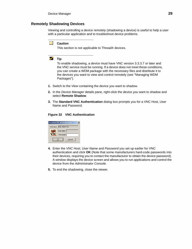
3. The Standard VNC Authentication dialog box prompts you for a VNC Host, User Name and Password.
Figure 32 VNC Authentication
4. Enter the VNC Host, User Name and Password you set up earlier for VNC authentication and click OK (Note that some manufacturers hard-code passwords into their devices, requiring you to contact the manufacturer to obtain the device password). A window displays the device screen and allows you to run applications and control the device from the Administrator Console.
5. To end the shadowing, close the viewer.

30 Chapter 3
Creating and Viewing Log FilesRight-clicking a device in the details pane of the Device Manager and selecting Get Logs allows you to create log files that you can view (enter a name, select the type of log file you want, and then click OK).
Figure 33 Creating Log Files
Right-clicking a device in the details pane of the Device Manager and selecting View Log allows you to select the log file you want to view (select the type of log file you want, select the log file name you want, and then click View Log).
Figure 34 Viewing Log Files
TipYou can also delete the log files you no longer need (select a log file name and click Delete Log).

Device Manager 31
Using the Package Distribution Wizard to Schedule a Package for Distribution1. Switch to the View containing the devices you want.
2. In the Device Manager details pane, select the devices to which you want to schedule a package for distribution (you can use CTRL+Click or SHIFT+Click to select multiple devices), right-click the selected devices, and then select Package Distribution Wizard to open the Package Distribution Wizard.
Figure 35 Package Category Selection
3. Select the package category folder that contains the registered WDM package you want to distribute and click Next. NOTE: Only images that support the operating system and flash size of the previously selected device groups view will be displayed.
Figure 36 Package Selection
4. Select the WDM package you want and click Next.

32 Chapter 3
Figure 37 Package Schedule
5. Select the scheduling options for the distribution, and then click Next.
Figure 38 Create Schedule
6. Select the imaging option you want and click Next.
7. After the package schedule is completed (update creation process is complete in the database), click Finish.

Device Manager 33
Using the Remote Task Manager to View Applications, Processes, and Performance for a Device
1. Switch to the View containing the device you want.
2. In the Device Manager details pane, select the single device for which you want to view the applications, processes, and performance.
3. Right-click the selected device, and then select Remote Task Manager to open the Remote Task Manager.
Figure 39 Application tab
4. On the Applications tab you can view the applications of the selected device (the window title bar displays the name of the device; the Mac Address and IP Address are displayed in the window status bar). You can also use the up-arrow and down-arrow to quickly display the information for the next or the previous device in the Device Manager details pane you previously selected. To refresh information, click Options > Refresh.
Figure 40 Processes tab
5. On the Processes tab you can view running processes of the selected device (the window title bar displays the name of the device; the Mac Address and IP Address are displayed in the window status bar). You can also use the up-arrow and down-arrow to quickly display the information for the next or the previous device in the Device Manager details pane you previously selected.

34 Chapter 3
Figure 41 Performance tab
6. On the Performance tab you can view the Memory, Total Page Files, Total Virtual Memory, and CPU Usage of the selected device (the window title bar displays the name of the device; the Mac Address and IP Address are displayed in the window status bar). You can also use the up-arrow and down-arrow to quickly display the information for the next or the previous device in the Device Manager details pane you previously selected.

4 Package Manager
This chapter describes how to perform routine WDM package management tasks using the Administrator Console. It provides information on managing the WDM packages (software, images, configurations, and so on) that can be distributed to the devices within your WDM environment.
Managing WDM PackagesClicking Package Manager in the tree pane of the WDM Administrator Console opens the Package Manager. The Package Manager allows you to quickly view and manage the WDM packages that can be distributed to the devices within your WDM environment (see Table 2). It also allows you to easily display the WDM packages you want by using the filtering and customizing features available.
Figure 42 Package Manager
Before using the Package Wizard to create and register WDM packages, you should understand the update distribution process and the contents of WDM packages, know the location of the existing WDM packages that you want to register, know the location of the base image and the Add-ons you want to add to it when creating CE bundled images, and ensure that the devices from which you will be getting images or configurations already have the WDM Agent installed. After WDM packages are registered, you can distribute them as updates to the devices within your WDM network (see "Update Manager").
TipIf you intend to perform WDM package registration and scheduling for all of the devices in your WDM system at the same time, the WDM Mass Imaging Tool can be a convenient way for you to easily perform these tasks (see "Using the WDM Mass Imaging Tool").

36 Chapter 4
Table 2 provides a quick overview of what you can do using the Package Manager.
Table 2 Routine Package Manager Tasks
Tasks You Can Do How Details
Create and register a WDM package from a script file (for example, from an .rsp file downloaded from the Wyse Web site) so it is ready to be distributed.
In the tree pane of the Administrator Console, right-click Package Manager, select New > Package to open the Package Wizard, select the Register a Package from a Script File (.RSP) option, and then follow the wizard.
"Register a Package from a Script File (.RSP)."TIP: For information on script files, see "WDM ScriptBuilder Tool and Scripting Language."
Create and register an image from a device (for example, from a device running XPE or CE) so it is ready to be distributed.
In the tree pane of the Administrator Console, right-click Package Manager, select New > Package to open the Package Wizard, select the Register an Image from a Device (Requires PXE) option, and then follow the wizard.TIP: You can also right-click the Reference Device and select Get Device Image to open and use the Package Wizard.
"Register an Image from a Device (Requires PXE)."
Create and register a configuration from a Wyse device running Wyse Enhanced SUSE Linux Enterprise or Linux v6.x so it is ready to be distributed.
In the tree pane of the Administrator Console, right-click Package Manager, select New > Package to open the Package Wizard, select the Register a Configuration from a Device option, and then follow the wizard.TIP: You can also right-click the Reference Device and select Get Device Configuration to open and use the Package Wizard.
"Register a Configuration from a Device" and "Registering a Configuration from Wyse Devices Running Wyse Enhanced SUSE Linux Enterprise or Linux v6.x."
Create and register a configuration from a Wyse device running Windows CE so it is ready to be distributed.
In the tree pane of the Administrator Console, right-click Package Manager, select New > Package to open the Package Wizard, select the Register a Configuration from a Device option, and then follow the wizard.TIP: You can also right-click the Reference Device and select Get Device Configuration to open and use the Package Wizard.
"Register a Configuration from a Device" and "Registering a Configuration from Wyse Devices Running Windows CE."

Package Manager 37
Create and register a CE image plus add-ons so it is ready to be distributed.
In the tree pane of the Administrator Console, right-click Package Manager, select New > Package to open the Package Wizard, select the Build and register a CE image plus add-ons (“CE bundled image”) option, and then follow the wizard.
"Build and Register a CE Image Plus Add-ons (CE Bundled Image)."
Create and register a ThreadX package (RDP, Video, or VMwareView) so it is ready to be distributed.
Use the guidelines in "Building and Registering a ThreadX Package." After creating these packages, you can drag drop a package to the devices you want, and then schedule their deployment accordingly.
"Building and Registering a ThreadX Package."
Use WISard to create and register an image from a device (for example, from a Wyse S series or V series device) so it is ready to be distributed.
For first-time use, complete the instructions in "Registering an Image from a Device Using WISard."TIP: After you have already set up the required preferences, you can expand the Device Manager (in the tree pane of the Administrator Console), right-click the device you want, and then select Get Device Image to open and use the Package Wizard.
"Registering an Image from a Device Using WISard: Initial Setup and Use" and "Registering an Image from a Device Using WISard: After Initial Setup."
Use Merlin to create and register an image from a device (for example, from a Wyse C class, R series, or X class device) so it is ready to be distributed.
For first-time use, complete the instructions in "Registering an Image from a Device Using Merlin."TIP: After you have already set up the required preferences, you can expand the Device Manager (in the tree pane of the Administrator Console), right-click the device you want, and then select Get Device Image to open and use the Package Wizard.
"Registering an Image from a Device Using Merlin: Initial Setup and Use" and "Registering an Image from a Device Using Merlin: After Initial Setup."
View the details of a registered WDM package.
In the tree pane of the Administrator Console, expand Package Manager and select the folder that contains the WDM package. In the details pane, right-click the WDM package and select Properties.
"Viewing the Details of a Registered WDM Package."
Table 2 Routine Package Manager Tasks , Continued
Tasks You Can Do How Details

38 Chapter 4
View and change the script of a registered WDM package.
In the tree pane of the Administrator Console, expand Package Manager and select the folder that contains the WDM package. In the details pane, right-click the WDM package and select View Package Script to open and use the Package Script dialog box.
"Viewing and Changing the Script of a Registered WDM Package."CAUTION: You cannot modify the script for default WDM packages.
Export the script of a registered WDM package to a folder you want.
In the tree pane of the Administrator Console, expand Package Manager and select the folder that contains the WDM package. In the details pane, right-click the WDM package and select Export Package Script to open and use the Browse for Folder dialog box.
"Exporting the Script of a Registered WDM Package."
Delete a registered WDM package from the system.
In the tree pane of the Administrator Console, expand Package Manager and select the folder that contains the WDM package. In the details pane, right-click the WDM package, select Delete, and then confirm the deletion.TIP: You can use CTRL+Click or SHIFT+Click to select multiple WDM packages.
You cannot delete default WDM packages. You cannot delete a registered WDM package that is scheduled for distribution; you must first delete the scheduled update as described in "Managing the Schedules for Device Updates" before you can delete a registered WDM package.WARNING: When you delete a registered WDM package that has never been distributed, WDM also deletes it from the WDM Repository. The WDM package is recoverable only if you have a copy of it outside of WDM. In such a case, you can re-register the WDM package.TIP: If you delete a WDM package that has already been distributed, you can recover it from the Backup folder of the WDM Repository and re-register it. When archived, a WDM package receives a date-stamped name, therefore, before re-registering an archived WDM package, you must rename it to its original name.
Table 2 Routine Package Manager Tasks , Continued
Tasks You Can Do How Details

Package Manager 39
Register a Package from a Script File (.RSP)1. In the tree pane of the Administrator Console, right-click Package Manager and select
New > Package to open the Package Wizard.
Figure 43 Package Wizard
2. Select the Register a Package from a Script File (.RSP) option and click Next.
3. Enter the File Path to the WDM script file (.rsp) file for the WDM package (for example, push_9V92_S550_512.rsp) you want to register (you can use Browse to find and select a file), and then click Next to open the Software Package Information dialog box.
Figure 44 Software Package Information
4. The Name, Description, and Category of the WDM package is obtained from the .rsp file and displayed.
5. Depending on whether or not you want to have the WDM package distributed (active for distribution), select or clear the Active check box.
6. Click Next. The wizard notifies you that is ready to create and register the new WDM package.
7. Click Next to create and register the WDM package.
8. After the WDM package has been created and registered, click Finish. The WDM package is copied to the Master Repository and is displayed under the appropriate category. The WDM package is now ready for distribution (see "Managing the Schedules for Device Updates").

40 Chapter 4
Register an Image from a Device (Requires PXE)This Package Wizard option requires that an Imaging Scripting Template exists for the Device Type. If no Imaging Scripting Template is available, a warning message will display (contact the manufacturer of the device to obtain an Imaging Scripting Template).
1. In the tree pane of the Administrator Console, right-click Package Manager and select New > Package to open the Package Wizard.
TipYou can also right-click the Reference Device in the details pane of the Device Manager and select Get Device Image to open the Package Wizard.
Figure 45 Package Wizard
2. Select the Register an Image from a Device (Requires PXE) option and click Next.
3. Enter a Name and Description for the Read Image WDM package that will read the image from a device (such as a Reference Device), and click Next (when you create the Read Image WDM package, ensure that the .rsp file contains values for the imagesize parameter and for the image number of the device upon which the image is based; proper .rsp files will have a well-formed header).
4. When the Package Wizard prompts you to select the group from which to read the image, select the group where the Reference Device is found and click Next.
5. When the Package Wizard prompts you to select the desired device, select the device whose image you want to read with the Get WDM package (be sure to select a Reference Device that supports PXE) and click Next.
6. Depending on your preferences, do one of the following:• (WISard Only) If you are using WISard, continue with step 7.• (Merlin Only) If you are using Merlin the Merlin Pulling Options dialog box
appears; select the options you want and then continue with step 7.
7. Click Next. The wizard notifies you that is ready to create and register the new WDM package.
8. Click Next to create and register the WDM package.
9. After the WDM package has been created and registered, click Finish. The image pull operation will appear in the details pane of the Update Manager. WDM will send the imaging job to the Reference Device. After completion of the pull operation, the pulled image will appear in the Images folder of the Package Manager (depending on the flash size of the device, the process to pull the image from the device may take some time). The WDM package is now ready for distribution (see "Managing the Schedules for Device Updates").

Package Manager 41
Register a Configuration from a DeviceThis Package Wizard option pulls a configuration from a device (such as a Reference Device) to easily configure (clone) similar devices within your WDM installation.
TipSupported devices for this functionality include Wyse devices running Wyse Enhanced SUSE Linux Enterprise, Linux v6.x, or Windows CE.
Prior to using the Package Wizard to pull and register the configuration from a Reference Device, ensure that:• The Reference Device supports Pre-boot Execute Environment (PXE).• You have configured the Reference Device to fulfill your specifications.• Tested the Reference Device and resolved any issues.
After you ensure your Reference Device is ready, you can continue using the Package Wizard to pull and register the configuration from the device according to your OS:• Wyse Devices Running Wyse Enhanced SUSE Linux Enterprise or Linux v6.x -
see "Registering a Configuration from Wyse Devices Running Wyse Enhanced SUSE Linux Enterprise or Linux v6.x"
• Wyse Devices Running Windows CE - see "Registering a Configuration from Wyse Devices Running Windows CE"
Registering a Configuration from Wyse Devices Running Wyse Enhanced SUSE Linux Enterprise or Linux v6.x 1. In the tree pane of the Administrator Console, right-click Package Manager and select
New > Package to open the Package Wizard.
TipYou can also right-click the Reference Device in the details pane of the Device Manager and select Get Device Configuration to open the Package Wizard.
Figure 46 Package Wizard
2. Select the Register a Configuration from a Device option and click Next.
3. Enter a Name and Description for the WDM package (the new WDM package will remain inactive until WDM successfully retrieves the configuration from the Reference Device).

42 Chapter 4
4. Click Next. The wizard notifies you that is ready to create and register the new WDM package.
5. Click Next to create and register the WDM package.
6. After the WDM package has been created and registered, click Finish. The WDM package is copied to the Master Repository and is displayed under the appropriate category. The WDM package is now ready for distribution (see "Managing the Schedules for Device Updates").
Registering a Configuration from Wyse Devices Running Windows CE
TipWith devices running Windows CE you can also control the action (Replace, Append, or exclude) of specific registry entries when later distributing the image.
1. In the tree pane of the Administrator Console, right-click Package Manager and select New > Package to open the Package Wizard.
TipYou can also right-click the Reference Device in the details pane of the Device Manager and select Get Device Configuration to open the Package Wizard.
Figure 47 Package Wizard
2. Select the Register a Configuration from a Device option and click Next.
3. Enter a Name and Description for the WDM package (the new WDM package will remain inactive until WDM successfully retrieves the configuration from the Reference Device).
4. Click Next.test

Package Manager 43
Figure 48 Replace or Append registry entries
5. Use the following guidelines:
TipThe entire configuration can either be replaced or appended to your Reference Device configuration when this WDM package is later distributed.
• Replace - Replacing the registry resets the registry to factory defaults and then applies the registry settings contained in the configuration (settings.reg) file of the WDM package (these are the registry settings you configured when preparing your Reference Device).
• Append - Appending the registry applies registry settings from the configuration (settings.reg) files of both devices (the existing registry settings of the existing device and the registry settings of your Reference Device). Note that duplicate registry settings are not affected.
• Exclude List - You can also exclude specific registry entries from being changed during distribution by selecting it in the list (selecting the check box next to the configuration setting).
6. Click Next. The wizard notifies you that is ready to create and register the new WDM package.
7. Click Next to create and register the WDM package.
8. After the WDM package has been created and registered, click Finish. The WDM package is copied to the Master Repository and is displayed under the appropriate category. The WDM package is now ready for distribution (see "Managing the Schedules for Device Updates").

44 Chapter 4
Build and Register a CE Image Plus Add-ons (CE Bundled Image)This Package Wizard option creates and registers a CE bundled image comprised of a CE OS image and add-ons.
1. In the tree pane of the Administrator Console, right-click Package Manager and select New > Package to open the Package Wizard.
Figure 49 Package Wizard
2. Select the Build and register a CE image plus add-ons (“CE bundled image”) option and click Next.
3. Enter a Name and Description for the CE bundled image and click Next. Notice that the Category box is read-only and displays Images as the category in which to store the CE bundled image.
4. Depending on whether or not you want to have the WDM package distributed (active for distribution), select or clear the Active check box.
5. Click Next.
6. Enter the CE version number and Base Image for the CE bundled image.
7. Browse to find and select the location of the Base CE Image, and optionally, for the location of the Registry Image in the CE Base box, and then click Next.
CautionThe CE Base image (or Primer) is generally a binary or executable file (most often the CE operating system). The CE bundled image creation process requires a params.ini file. This file should reside in the same directory from which you obtain the CE base image. The wizard obtains the build version information from the params.ini file. If the file is not available, the CE bundled image creation process will stop.
8. The wizard prompts you to select Add-ons for the CE bundled image. Click Select File to navigate and select the location where known Add-ons reside, and then select the Add-ons you want.
TipThe Add-on and Build boxes display the name and build for each Add-on you want. The Add-On selection dialog box will display your selected Add-ons and allow you to continue making additional Add-on selections. To remove Add-ons from your selections, select them (you can use CTRL+Click or SHIFT+Click to select multiple items), and then click Remove (you can click Remove All to delete all the Add-ons).

Package Manager 45
CautionThe Add-on is generally a binary, executable, or registry file. The CE bundled image creation process requires a params.ini file for each Add-on that you select. This file should reside in the same directory from which you obtain the Add-on. The wizard obtains the Add-on build version information from the params.ini file. If the file is not available, the CE bundled image creation process will stop.
9. When you have finished selecting the Add-ons you want, click Next. The wizard informs you that it is ready to create the WDM package for your CE Bundled image.
10.Click Next. The wizard notifies you that is ready to create and register the new WDM package.
11.Click Next to create and register the WDM package.
12.After the WDM package has been created and registered, click Finish. The WDM package is copied to the Master Repository and is displayed under the appropriate category. The WDM package is now ready for distribution (see "Managing the Schedules for Device Updates").

46 Chapter 4
Building and Registering a ThreadX PackageThe following configuration packages can be built and registered for mass deployment to ThreadX devices:• RDP Packages: An RDP package can be deployed to ThreadX devices to configure
global RDP settings.• Video Packages: A video package can be deployed to ThreadX devices to configure
global video settings such as minimum and maximum image quality settings.• VMwareView Packages: A VMwareView package can be deployed to the ThreadX
devices to configure the VDM server settings.
After creating these packages, you can drag drop a package to the devices you want, and then schedule their deployment accordingly (for more information on scheduling packages, see "Update Manager").
TipYou can use the default/sample ThreadX packages that are bundled with WDM or you can modify these default/sample ThreadX packages to create customized RDP, Video, and VMWareView packages that you can register and deploy to ThreadX devices. The default/sample ThreadX packages are located in the ThreadX Configuration folder (under the Package Manager node).
Use the following guidelines to create customized ThreadX packages from the default/sample ThreadX packages (use the same guidelines in the RDP example for creating Video and VMwareView packages):
Example of creating a customized RDP ThreadX package:
1. Create a folder of any name which starts with an RDP prefix, for example, RDPTest1.
2. Within the folder you created (in our example, RDPTest1) create a file named RDPTest1.rsp with the following content:
"[Version] Number=RDPTest1Description=Customized ThreadX Device RDPOS=TDCCategory=ThreadX Configuration
[Script]Bit_Depth=24Resolution=800X600Terminal_Server_Port=3076"
3. Be sure in the RSP script that the "Number=" segment has the exact same value as the RSP file name and folder name (again this same principle is applicable to both Video and VMwareView packages where the same convention is to be followed in naming custom packages).
4. It is recommended that you place the package into the ThreadX Configuration folder (under the Package Manager node). You can later drag drop a package to the devices you want and schedule their deployment accordingly (see "Update Manager").

Package Manager 47
Registering an Image from a Device Using WISard Depending on whether or not you have set up the required preferences so that the Package Wizard automatically uses WISard to create and register an image, complete one of the following:• If you have not set up the required preferences (for, example, this is the first time you
are using WISard to create and register an image), complete the procedures in "Registering an Image from a Device Using WISard: Initial Setup and Use" (this will take you through the entire process to set up the preferences and use WISard to create and register an image).
• If you have already set up the required preferences (for, example, you have already used WISard to create and register an image), complete the procedures in "Registering an Image from a Device Using WISard: After Initial Setup" (this will take you through the shortened process to use WISard to create and register an image).
CautionWISard requires that PXE is enabled in the BIOS of the device. Wyse thin clients come with PXE enabled by default. No configuration changes are required on the device to perform a network boot. For more information on PXE usage, see "PXE Based Imaging.".
Registering an Image from a Device Using WISard: Initial Setup and Use
TipAfter completing this section, you can use the shortened process (“Registering an Image from a Device Using WISard: After Initial Setup” on page 49) to use WISard to create and register an image in the future.
1. In the tree pane of the Administrator Console, navigate to WyseDeviceManager > Configuration Manager > Software Repositories.
2. In the details pane, right-click Master and select Properties.
Figure 50 Software Repository: Master Repository

48 Chapter 4
3. In the Software Repository dialog box, select FTP in the Transfer Type list for the Master Repository and click OK.
4. In the tree pane of the Administrator Console, navigate to WyseDeviceManager > Configuration Manager > Preferences.
5. In the results pane, double-click Service Preferences to open the Preferences window.
6. In the tree pane of the Preferences window, select Service.
Figure 51 Preferences: Service Preferences
7. In the Repository Preferences area, select the FTP check box.
8. In the tree pane of the Preferences window, select Scheduling.
Figure 52 Preferences: Scheduling Preferences
9. In the Imaging Option area, select the WISard option.
10.In the tree pane of the Preferences window, select DHCP/TFTP.

Package Manager 49
Figure 53 Preferences: DHCP/TFTP Preferences
11. In the TFTP Server Preferences area, select the Start TFTP check box.
12.Click OK.
13.Now that you have set up the required preferences, continue with "Registering an Image from a Device Using WISard: After Initial Setup."
Registering an Image from a Device Using WISard: After Initial Setup
CautionBefore using this section, be sure you have completed the procedures in “Registering an Image from a Device Using WISard: Initial Setup and Use” on page 47.
1. In the tree pane of the Administrator Console, expand the Device Manager.
2. Right-click the device you want and then select Get Device Image to open the Package Wizard.
3. Enter the Name and Description of the WDM package.
4. Click Next. The wizard notifies you that is ready to create and register the new WDM package.
5. Click Next to create and register the WDM package.
6. After the WDM package has been created and registered, click Finish. WDM starts the image pull operation from the device (the device goes through a PXE boot and WISard imaging process) and creates the image. The WDM package is copied to the Master Repository and is displayed under the appropriate category. The WDM package is now ready for distribution (see "Managing the Schedules for Device Updates").

50 Chapter 4
Registering an Image from a Device Using Merlin Depending on whether or not you have set up the required preferences so that the Package Wizard automatically uses Merlin to create and register an image, complete one of the following:• If you have not set up the required preferences (for, example, this is the first time you
are using Merlin to create and register an image), complete the procedures in "Registering an Image from a Device Using Merlin: Initial Setup and Use" (this will take you through the entire process to set up the preferences and use Merlin to create and register an image).
• If you have already set up the required preferences (for, example, you have already used Merlin to create and register an image), complete the procedures in "Registering an Image from a Device Using Merlin: After Initial Setup" (this will take you through the shortened process to use Merlin to create and register an image).
CautionMerlin can be used with a PXE or Non-PXE option for devices running XPe, WES, or WES 7. For other devices, Merlin requires that PXE is enabled in the BIOS of the device. Wyse thin clients come with PXE enabled by default. No configuration changes are required on the device to perform a network boot. For more information on PXE and Non-PXE usage, see "PXE Based Imaging."
Registering an Image from a Device Using Merlin: Initial Setup and Use
TipAfter completing this section, you can use the shortened process (“Registering an Image from a Device Using Merlin: After Initial Setup” on page 52) to use Merlin to create and register an image in the future.
1. In the tree pane of the Administrator Console, navigate to WyseDeviceManager > Configuration Manager > Software Repositories.
2. In the details pane, right-click Master and select Properties.

Package Manager 51
Figure 54 Software Repository: Master repository
3. In the Software Repository dialog box, select the Transfer Type (Merlin supports both HTTP and FTP) for the Master Repository.
4. In the tree pane of the Administrator Console, navigate to WyseDeviceManager > Configuration Manager > Preferences.
5. In the results pane, double-click Service Preferences to open the Preferences window.
6. In the tree pane of the Preferences window, select Service.
Figure 55 Preferences: Service Preferences
7. In the Repository Preferences area, select the Repository Preferences option you want (Merlin supports both HTTP and FTP).
8. In the tree pane of the Preferences window, select Scheduling.

52 Chapter 4
Figure 56 Preferences: Scheduling Preferences
9. In the Imaging Option area, select the Merlin option, and then select the Network Card Speed that matches the network speed of the subnet in which the device exists.
10.In the tree pane of the Preferences window, select DHCP/TFTP.
Figure 57 Preferences: DHCP/TFTP Preferences
11. In the TFTP Server Preferences area, click the Start TFTP check box.
12.Click OK.
13.Now that you have set up the required preferences, continue with "Registering an Image from a Device Using Merlin: After Initial Setup."
Registering an Image from a Device Using Merlin: After Initial Setup
CautionBefore using this section, be sure you have completed the procedures in “Registering an Image from a Device Using Merlin: Initial Setup and Use” on page 50.
1. In the tree pane of the Administrator Console, expand the Device Manager.
2. Right-click the device you want and then select Get Device Image to open the Package Wizard.
3. Enter the Name and Description of the WDM package.
4. Click Next.

Package Manager 53
Figure 58 Merlin options
5. Use the following guidelines to select the options you want:• Merlin Pulling Options
· All - Pulls CMOS, BIOS, and OS (including any Non-PXE partitions if any exist).· CMOS and BIOS - Pulls CMOS and BIOS only.· OS - Pulls OS only (including any Non-PXE partitions if any exist).
• Imaging Option (available only for devices running XPe, WES, or WES 7)· PXE - If selected, imaging occurs in PXE mode.· Non PXE - If selected, imaging occurs in Non-PXE mode.
6. Click Next. The wizard notifies you that is ready to create and register the new WDM package.
7. Click Next to create and register the WDM package.
8. After the WDM package has been created and registered, click Finish. WDM starts the image pull operation from the device (if PXE is selected, the device goes through a PXE boot and Merlin imaging process) and creates the image. The WDM package is copied to the Master Repository and is displayed under the appropriate category. The WDM package is now ready for distribution (see "Managing the Schedules for Device Updates").

54 Chapter 4
Viewing the Details of a Registered WDM Package1. In the tree pane of the Administrator Console, expand Package Manager and select
the folder that contains the WDM package you want to view.
Figure 59 WDM Package Properties
2. In the details pane, right-click the WDM package and select Properties to open the Edit Package dialog box displaying the details of the WDM package.
Figure 60 Edit Package
The Edit Package dialog box displays:• Name - Name of the WDM package.• Description - Description of the WDM package.• Active - If selected, allows distribution of the WDM package to a device; if cleared, the
WDM package cannot be distributed to a device.• Operating System - The operating system for which this WDM package is compatible.• Size - Size of the WDM package in kilobytes.• Date Created - WDM package creation date and time.

Package Manager 55
Viewing and Changing the Script of a Registered WDM Package
TipUsing WDM Scripting Language: WDM Scripting Language is a simplified scripting language that you can use to build your own WDM packages. You can also use it to perform basic tasks such as copying files and modifying the registry of the devices that WDM manages. WDM Scripting Language is not a programming language (it does not support looping, branching, and the use of subroutines). However, it does contain a small command set to allow it to perform a variety of routine functions such as checking the operating system version on a given device (see "WDM ScriptBuilder Tool and Scripting Language").
CautionYou cannot modify the script for default WDM packages.
1. In the tree pane of the Administrator Console, expand Package Manager and select the folder that contains the WDM package you want to view.
Figure 61 View WDM Package Script
2. In the details pane, right-click the WDM package and select View Package Script to open the Package Script dialog box displaying the script of the WDM package.
Figure 62 Package Script
3. Select the Edit and Save Script to Database ONLY check box and then make your changes to the script of the .rsp file.
4. After completing your changes, click OK.

56 Chapter 4
Exporting the Script of a Registered WDM Package1. In the tree pane of the Administrator Console, expand Package Manager and select
the folder that contains the WDM package you want to view.
Figure 63 View WDM Package Script
2. In the details pane, right-click the WDM package, select Export Package Script to open the Browse for Folder dialog box.
3. Select the folder to which you want to export the script of the WDM package, and then confirm.

5 Update Manager
This chapter describes how to perform routine device update management tasks using the Administrator Console. It provides information on managing the device updates in your WDM system and the schedules for synchronizations between Remote Repositories and the Master Repository.
Managing the Schedules for Device UpdatesClicking Update Manager in the tree pane of the WDM Administrator Console opens the Update Manager. The Update Manager allows you to quickly view and manage the device updates (schedules of the WDM packages registered in the WDM database that are ready to be distributed to devices) within your WDM environment (see Table 3). It also allows you to view and manage the schedules for synchronizations between Remote Repositories and the Master Repository.
Figure 64 Update Manager
Before using the Update Wizard to schedule device updates, you should understand the update distribution process and the contents of the registered WDM packages, know the identity of the WDM packages that you want to distribute, and ensure that the devices to which you will be pushing images or configurations are recognized by the WDM system (for example, they have been discovered by WDM). After the WDM packages in the WDM database are scheduled for distribution, they will be distributed as updates to the devices within your WDM network according to your schedules and preferences.
TipIf you intend to perform WDM package registration and scheduling for all of the devices in your WDM system at the same time, the WDM Mass Imaging Tool can be a convenient way for you to easily perform these tasks (see "Using the WDM Mass Imaging Tool").
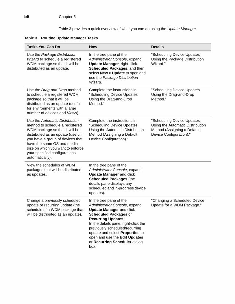
58 Chapter 5
Table 3 provides a quick overview of what you can do using the Update Manager.
Table 3 Routine Update Manager Tasks
Tasks You Can Do How Details
Use the Package Distribution Wizard to schedule a registered WDM package so that it will be distributed as an update.
In the tree pane of the Administrator Console, expand Update Manager, right-click Scheduled Packages, and then select New > Update to open and use the Package Distribution Wizard.
"Scheduling Device Updates Using the Package Distribution Wizard."
Use the Drag-and-Drop method to schedule a registered WDM package so that it will be distributed as an update (useful for environments with a large number of devices and Views).
Complete the instructions in "Scheduling Device Updates Using the Drag-and-Drop Method."
"Scheduling Device Updates Using the Drag-and-Drop Method."
Use the Automatic Distribution method to schedule a registered WDM package so that it will be distributed as an update (useful if you have a group of devices that have the same OS and media size on which you want to enforce your specified configurations automatically).
Complete the instructions in "Scheduling Device Updates Using the Automatic Distribution Method (Assigning a Default Device Configuration)."
"Scheduling Device Updates Using the Automatic Distribution Method (Assigning a Default Device Configuration)."
View the schedules of WDM packages that will be distributed as updates.
In the tree pane of the Administrator Console, expand Update Manager and click Scheduled Packages (the details pane displays any scheduled and in-progress device updates).
Change a previously scheduled update or recurring update (the schedule of a WDM package that will be distributed as an update).
In the tree pane of the Administrator Console, expand Update Manager and click Scheduled Packages or Recurring Updates.In the details pane, right-click the previously scheduled/recurring update and select Properties to open and use the Edit Updates or Recurring Scheduler dialog box.
"Changing a Scheduled Device Update for a WDM Package."

Update Manager 59
Delete a previously scheduled update (the schedule of a WDM package that will be distributed as an update).
In the tree pane of the Administrator Console, expand Update Manager and select Scheduled Packages. In the details pane, right-click the previously scheduled update, select Delete, and then confirm the deletion.TIP: You can use CTRL+Click or SHIFT+Click to select multiple WDM packages.
You cannot delete in-progress device updates for a WDM package.TIP: If you have an in-progress update that cannot be fulfilled (for example, a device problem), you can move the update to an error state (right-click on the update and select Move to Error) and then delete it.
(WDM Enterprise Edition Only) Select an Update Manager View (defaults or one that you created) to use with Scheduled Packages so you can quickly find the devices you want.
In the tree pane of the Administrator Console, expand Update Manager, right-click Scheduled Packages, and then select Switch View to open and use the Select Current Manager View dialog box.
After creating Views according to your device Group Types, Networks, and so on, selecting a Current Manager View makes it easy to view the devices you want (see "Managing Views").
(WDM Enterprise Edition Only) Use the Remote Software Repository Synchronization Wizard to manually schedule a synchronization.
In the tree pane of the Administrator Console, expand Update Manager, right-click Software Repository Synchronization, and then select New > Remote SW Repository Synch to open the Remote Software Repository Synchronization Wizard.
"Manually Scheduling a Synchronization (Using the Remote Software Repository Synchronization Wizard)."
(WDM Enterprise Edition Only) Set up or change an automatic synchronization.
Complete the instructions in "Configuring an Automatic Synchronization."
"Configuring an Automatic Synchronization."NOTE: Automatic synchronization is the default set during installation. Use these instructions if you ever need to change a manual synchronization schedule back to an automatic schedule, or simply need to change the time settings on your current automatic schedule.
(WDM Enterprise Edition Only) View the schedules of remote repository synchronizations.
In the tree pane of the Administrator Console, expand Update Manager and click Software Repository (the details pane displays any scheduled, error-state, or in-progress remote repository synchronizations).
Table 3 Routine Update Manager Tasks , Continued
Tasks You Can Do How Details

60 Chapter 5
(WDM Enterprise Edition Only) Change the schedule of a remote repository synchronization.
In the tree pane of the Administrator Console, expand Update Manager and click Software Repository Synchronization. In the details pane, right-click the scheduled synchronization and select Properties to open and use the Synchronize Remote Software Repository dialog box.
"WDM Enterprise Edition Only: Changing a Remote Software Repository Synchronization."
(WDM Enterprise Edition Only) Delete a previously scheduled remote repository synchronization.
In the tree pane of the Administrator Console, expand Update Manager and click Software Repository Synchronization. In the details pane, right-click the previously scheduled synchronization, select Delete, and then confirm the deletion.
You cannot delete in-progress remote repository synchronizations.
Table 3 Routine Update Manager Tasks , Continued
Tasks You Can Do How Details

Update Manager 61
Scheduling Device Updates Using the Package Distribution Wizard1. In the tree pane of the Administrator Console, expand Update Manager, right-click
Scheduled Packages, select Switch View to open the Update Manager View dialog box, select the view that contains the group or groups of devices you want to receive the update, and then click OK (note that you can use New to create a new view).
Figure 65 Select View
2. In the tree pane of the Administrator Console, right-click Scheduled Packages and select New > Update to open the Package Distribution Wizard.
Figure 66 Package Distribution Wizard
3. Select the folder that contains the registered WDM package you want to distribute and click Next. NOTE: Only images that support the operating system and flash size of the previously selected device groups view will be displayed.
Figure 67 Select the WDM package
4. Select the WDM package you want and click Next.

62 Chapter 5
Figure 68 Select client groups
5. Select the group of devices you want to receive the update (to select all of the groups in the hierarchy, select Device Manager at the top of the hierarchy) and click Next.
TipThe device groups you see depend on the Update Manager View you selected in step 1).
Figure 69 Select clients
6. Use the dialog box to select the devices you want to receive the update (you can use CTRL+Click or SHIFT+Click to select multiple devices; or click Select All if you want to select all of the devices in the list), select or clear the Recurring Update check box (allowing you to schedule on a recurring basis), and then click Next.
7. Depending on whether or not any of the devices you selected are serviced by a Remote Repository (for example, the WDM package with the update is contained in a Remote Repository), complete one of the following:• If no, the wizard prompts you to select when the update/recurrence pattern should
occur. Select the times/dates for the update, click Next, and then continue with step 8.
• If yes (WDM Enterprise Edition Only) and you have set up your preferences to synchronize Remote Repositories, the wizard prompts you for the synchronization information. Enter the information, click Next, and then continue with step 8.
8. When prompted to create the updates click Next.
9. After the wizard notifies you that the updates have been created, click Finish.

Update Manager 63
Scheduling Device Updates Using the Drag-and-Drop MethodYou can use the Drag-and-Drop method to schedule a registered WDM package so that it will be distributed as an update (useful for environments with a large number of devices and Views).
TipYou can create the View you want (a folder that includes the devices to which you want to distribute a WDM package) by using the instructions in "Managing Views."
1. In the tree pane of the Administrator Console, expand Package Manager and click the folder that contains the WDM package you want to distribute so that it is displayed in the details pane.
2. In the tree pane of the Administrator Console, expand Device Manager so that the folder containing the devices (the View) to which you want to distribute the WDM package is displayed in the tree pane.
3. Click and drag the WDM package you want to distribute from the details pane and drop the WDM package onto the folder in the tree pane containing the devices (the View) to which you want to distribute the WDM package.
Figure 70 Select devices
4. User the Package Distribution Wizard that appears to select the devices you want to receive the WDM package, click the arrow to move them to the Selected Devices list (you can use CTRL+Click or SHIFT+Click to select multiple devices; or click Select All if you want to select all of the devices in the list), select or clear the Recurring Update check box (allowing you to schedule on a recurring basis for time, day, and range of dates after you click Next; for example, every two weeks on Monday at 3:00 A.M. with no end date), and then click Next.
5. Depending on whether or not any of the devices you selected are serviced by a Remote Repository (for example, the WDM package with the update is contained in a Remote Repository), complete one of the following:• If no, the wizard prompts you to select when the update/recurrence pattern should
occur. Select the time, date, and so on for the update, click Next, and then continue with step 6.
• If yes (WDM Enterprise Edition Only) and you have set up your preferences to synchronize Remote Repositories, the wizard prompts you for the synchronization information. Enter the information, click Next, and then continue with step 6.
6. When prompted to create the updates click Next.
7. After the wizard notifies you that the updates have been created, click Finish.

64 Chapter 5
Scheduling Device Updates Using the Automatic Distribution Method (Assigning a Default Device Configuration)
If you have a group of devices that have the same OS and media size, you can assign a Default Device Configuration (DDC) to update the devices automatically. A DDC allows you to set default configurations for a group of devices and ensures that the devices conform to your configurations. That is, if there is any deviation from your default configurations, WDM will revert the devices back to your specified configurations automatically (WDM automatically sends the WDM packages in the DDC to the devices according to your schedule and without your intervention).
1. Determine the target devices you want to use with the DDC - Identify the devices to which you want to assign a DDC, and create a suitable View to isolate the target devices (a DDC can only be applied to a group of devices that have the same OS and media size).
TipYou can create the View you want (a folder that includes the devices to which you want to distribute a WDM package) by using the instructions in "Managing Views."
2. Determine the WDM packages you want to use with the DDC - Identify the registered WDM packages (in the WDM Database) that you want to include in the DDC.
TipDDCs also allow you to determine the sequence in which the WDM packages are distributed to the devices.
3. Create and assign the DDC - Use the procedures in "Managing Default Device Configurations" to create and assign the DDC you want.
Changing a Scheduled Device Update for a WDM Package
CautionYou cannot edit in-progress device updates. If a device has been removed from a network before deleting a scheduled update for that device, the scheduled update may remain in a status of in-progress indefinitely. Before you delete a device, be sure there is no update scheduled for that device.
1. In the tree pane of the Administrator Console, expand Update Manager, and then depending on your scheduled package click Scheduled Packages or Recurring Updates. The details pane displays any scheduled, error-state, or in-progress device updates.
Figure 71 Edit Scheduled Updates

Update Manager 65
2. Right-click the scheduled/recurring device update you want to change and select Properties to open the Edit Updates or Recurring Scheduler dialog box.
Figure 72 Edit Updates/Recurring Scheduler
3. Make your changes (the ability to select the Next Time the Device Boots option requires that the device supports PXE and that you set up your preferences to allow updates to occur at PXE if you are using PXE-based imaging - see "PXE Based Imaging").
Tip(WDM Enterprise Edition Only) If the scheduled device update is linked to a Remote Repository, you may see two update rows in the details pane of the Software Repository Synchronization window. The first row is for an update to synchronize the Remote Repository with the Master Repository (if necessary). The second row is for the actual update to the devices that are serviced by the Remote Repository. You can edit either or both of these updates. However, you cannot reschedule the synchronization update (between the Remote Repository and the Master Repository) to occur after the update for the corresponding devices.
4. After completing your changes, click OK.

66 Chapter 5
WDM Enterprise Edition Only: Scheduling a Remote Repository Synchronization
Although by default (set using a check box during installation) WDM automatically synchronizes the Remote Repository with the Master Repository after a Remote Repository installation, WDM packages in Remote Repositories can be synchronized by:• Configuring an Automatic Synchronization - This is the default set during
installation. Automatic synchronization occurs when a client device receives an update for a WDM package that is not included in the repository assigned to the client’s subnet (see "Configuring an Automatic Synchronization").
• Manually Scheduling a Synchronization - Using the Remote Software Repository Synchronization Wizard, you can set up the specific schedules you need (see "Manually Scheduling a Synchronization (Using the Remote Software Repository Synchronization Wizard)").
Configuring an Automatic SynchronizationAutomatic synchronization is the default set during installation. If you ever need to change a manual synchronization schedule back to an automatic schedule, or simply need to change the time settings on your current automatic schedule, use the following guidelines:
1. In the tree pane of the Administrator Console, expand Configuration Manager, and then click Preferences.
2. In the details pane, double-click Scheduling Preferences to open the Preferences dialog box.
3. In the left pane of the Preferences dialog box, click Scheduling to open the Scheduling Preferences dialog box.
4. Enter the General Scheduling Preferences you want (see "Scheduling Preferences").
5. Select the Auto-synch Remote Software Repository check box and select the Max. Retry Count you want (5 is generally recommended).
6. Select the Imaging Option you want (see "Scheduling Preferences").
7. Click OK.

Update Manager 67
Manually Scheduling a Synchronization (Using the Remote Software Repository Synchronization Wizard)
1. In the tree pane of the Administrator Console, expand Update Manager, right-click Software Repository Synchronization, and then select New > Remote SW Repository Synch to open the Remote Software Repository Synchronization Wizard.
Figure 73 Remote Software Repository Synchronization Wizard
2. Select the category containing the WDM package you want to synchronize, and then click Next.
Figure 74 Select the WDM package
3. Select the WDM package you want to synchronize, and then click Next.
Figure 75 Select the Software Repository
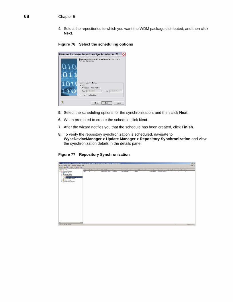
68 Chapter 5
4. Select the repositories to which you want the WDM package distributed, and then click Next.
Figure 76 Select the scheduling options
5. Select the scheduling options for the synchronization, and then click Next.
6. When prompted to create the schedule click Next.
7. After the wizard notifies you that the schedule has been created, click Finish.
8. To verify the repository synchronization is scheduled, navigate to WyseDeviceManager > Update Manager > Repository Synchronization and view the synchronization details in the details pane.
Figure 77 Repository Synchronization
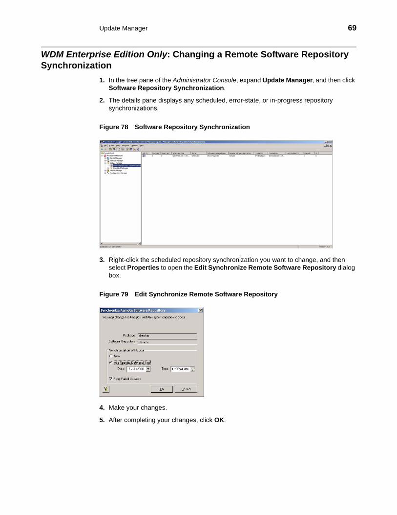
Update Manager 69
WDM Enterprise Edition Only: Changing a Remote Software Repository Synchronization
1. In the tree pane of the Administrator Console, expand Update Manager, and then click Software Repository Synchronization.
2. The details pane displays any scheduled, error-state, or in-progress repository synchronizations.
Figure 78 Software Repository Synchronization
3. Right-click the scheduled repository synchronization you want to change, and then select Properties to open the Edit Synchronize Remote Software Repository dialog box.
Figure 79 Edit Synchronize Remote Software Repository
4. Make your changes.
5. After completing your changes, click OK.

70 Chapter 5
This page intentionally blank.
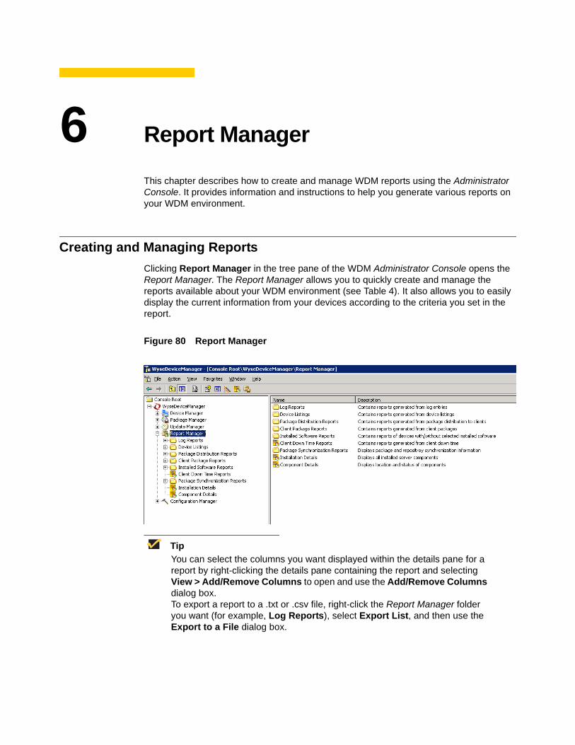
6 Report Manager
This chapter describes how to create and manage WDM reports using the Administrator Console. It provides information and instructions to help you generate various reports on your WDM environment.
Creating and Managing ReportsClicking Report Manager in the tree pane of the WDM Administrator Console opens the Report Manager. The Report Manager allows you to quickly create and manage the reports available about your WDM environment (see Table 4). It also allows you to easily display the current information from your devices according to the criteria you set in the report.
Figure 80 Report Manager
TipYou can select the columns you want displayed within the details pane for a report by right-clicking the details pane containing the report and selecting View > Add/Remove Columns to open and use the Add/Remove Columns dialog box.To export a report to a .txt or .csv file, right-click the Report Manager folder you want (for example, Log Reports), select Export List, and then use the Export to a File dialog box.

72 Chapter 6
Table 4 provides a quick overview of what you can do using the Report Manager.
Table 4 Routine Report Manager Tasks
Tasks You Can Do How Details
Create a report listing activities related to all WDM components according to your logging preferences (for example, all administrator activities within a start and end time).
In the tree pane of the Administrator Console, expand Report Manager, right-click Log Reports, and then select New > Report to open and use the Report Wizard.
"Log Reports."TIP: To set your logging preferences, see "Logging Preferences."
Create a report listing WDM devices according to your criteria (for example, all devices according to operating system).
In the tree pane of the Administrator Console, expand Report Manager, right-click Device Listings, and then select New > Report to open and use the Report Wizard.
"Device Listings."
Create a report with information about WDM devices according to the WDM packages you have distributed (for example, all devices according to a specific WDM package update).
In the tree pane of the Administrator Console, expand Report Manager, right-click Package Distribution Reports, and then select New > Report to open and use the Report Wizard.
"Package Distribution Reports."
Create a report with information about the WDM packages you have distributed according to the devices in your WDM environment (for example, all WDM package updates according to a specific WDM device).
In the tree pane of the Administrator Console, expand Report Manager, right-click Client Package Reports, and then select New > Report to open and use the Report Wizard.
"Client Package Reports."
Create a report with information about the software installed on the devices in your WDM environment according to your criteria (for example, software according to subnet).
In the tree pane of the Administrator Console, expand Report Manager, right-click Installed Software Reports, and then select New > Report to open and use the Report Wizard.
"Installed Software Reports."
Create a Client Down Time Report to view information about the down-time period for specific devices in your WDM environment.
In the tree pane of the Administrator Console, expand Report Manager, click to highlight Client Down Time Reports, and then click the Create a New Report toolbar icon to open and use the Report Wizard.
"Client Down Time Reports."
Display an Installation Details report to view information about the installed components of WDM.
In the tree pane of the Administrator Console, expand Report Manager and select Installation Details to view the report in the details pane.
"Installation Details Report."

Report Manager 73
Display a Component Details report to view information about the running components of WDM.
In the tree pane of the Administrator Console, expand Report Manager and select Component Details to view the report in the details pane.
"Component Details Report."
(WDM Enterprise Edition Only) Create a Package Synchronization History report to view the details of WDM package synchronizations for each WDM package in the Master Repository with a Remote Repository.
In the tree pane of the Administrator Console, expand Report Manager, expand Package Synchronization Reports, and then select Package Synchronization History to view the report in the details pane.
"Package Synchronization History Reports."See also "Package Synchronization Reports."
(WDM Enterprise Edition Only) Create an Unsynchronized Packages report to view the details of WDM package synchronizations that have not taken place for WDM packages in the Master Repository with a Remote Repository.
In the tree pane of the Administrator Console, expand Report Manager, expand Package Synchronization Reports, and then select Unsynchronized Packages Report to view the report in the details pane.
"Unsynchronized Packages Reports."See also "Package Synchronization Reports."
(WDM Enterprise Edition Only) Create an Orphaned Package report to view the details of WDM packages that still remain in the Remote Repository while the related WDM packages have been deleted in the Master Repository.
In the tree pane of the Administrator Console, expand Report Manager, expand Package Synchronization Reports, and then select Orphaned Package Report to view the report in the details pane.
"Orphaned Package Reports."See also "Package Synchronization Reports."
Table 4 Routine Report Manager Tasks , Continued
Tasks You Can Do How Details

74 Chapter 6
Log ReportsLog Reports provide information about the activities related to all WDM components according to your logging preferences (see "Logging Preferences").
TipOnce you create a Log Report, WDM automatically saves the criteria and there is no need to create that report again. Each time you view the report (click the report name in the appropriate folder) you see current information according to the criteria you set. You can also refresh a report by right-clicking the folder containing the report and selecting Refresh.
1. In the tree pane of the Administrator Console, expand Report Manager, right-click Log Reports and select New > Report to open the Report Wizard.
2. Enter a Name and Description for the report (so you can easily recognize it later) and click Next.
Figure 81 Start and End options
3. Select the start and end options you want, and then click Next.
Figure 82 Specify Users
4. Select the option you want from the User list, and then click Finish to create the report.
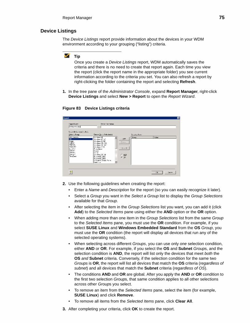
Report Manager 75
Device ListingsThe Device Listings report provide information about the devices in your WDM environment according to your grouping (“listing”) criteria.
TipOnce you create a Device Listings report, WDM automatically saves the criteria and there is no need to create that report again. Each time you view the report (click the report name in the appropriate folder) you see current information according to the criteria you set. You can also refresh a report by right-clicking the folder containing the report and selecting Refresh.
1. In the tree pane of the Administrator Console, expand Report Manager, right-click Device Listings and select New > Report to open the Report Wizard.
Figure 83 Device Listings criteria
2. Use the following guidelines when creating the report:• Enter a Name and Description for the report (so you can easily recognize it later).• Select a Group you want in the Select a Group list to display the Group Selections
available for that Group.• After selecting the item in the Group Selections list you want, you can add it (click
Add) to the Selected Items pane using either the AND option or the OR option. • When adding more than one item in the Group Selections list from the same Group
to the Selected Items pane, you must use the OR condition. For example, if you select SUSE Linux and Windows Embedded Standard from the OS Group, you must use the OR condition (the report will display all devices that run any of the selected operating systems).
• When selecting across different Groups, you can use only one selection condition, either AND or OR. For example, if you select the OS and Subnet Groups, and the selection condition is AND, the report will list only the devices that meet both the OS and Subnet criteria. Conversely, if the selection condition for the same two Groups is OR, the report will list all devices that match the OS criteria (regardless of subnet) and all devices that match the Subnet criteria (regardless of OS).
• The conditions AND and OR are global. After you apply the AND or OR condition to the first two selection Groups, that same condition applies to all other selections across other Groups you select.
• To remove an item from the Selected Items pane, select the item (for example, SUSE Linux) and click Remove.
• To remove all items from the Selected Items pane, click Clear All.
3. After completing your criteria, click OK to create the report.

76 Chapter 6
Package Distribution ReportsPackage Distribution Reports provide information about WDM devices according to the WDM packages you have distributed.
TipOnce you create a Package Distribution Report, WDM automatically saves the criteria and there is no need to create that report again. Each time you view the report (click the report name in the appropriate folder) you see current information according to the criteria you set. You can also refresh a report by right-clicking the folder containing the report and selecting Refresh.
1. In the tree pane of the Administrator Console, expand Report Manager, right-click Package Distribution Reports and select New > Report to open the Report Wizard.
Figure 84 Package Distribution Reports criteria
2. Use the following guidelines when creating the report:• Enter a Name and Description for the report (so you can easily recognize it later).• Select a Group you want in the Select a Group list to display the Group Selections
available for that Group.• After selecting the items in the Group Selections list you want, you can add them
(click Add) to the Selected Items pane. • To remove an item from the Selected Items pane, select the item (for example,
Update5XPE) and click Remove.• To remove all items from the Selected Items pane, click Clear All.
3. After completing your criteria, click OK to create the report.

Report Manager 77
Client Package ReportsClient Package Reports provide information about the WDM packages you have distributed according to the devices in your WDM environment.
TipOnce you create a Client Package Report, WDM automatically saves the criteria and there is no need to create that report again. Each time you view the report (click the report name in the appropriate folder) you see current information according to the criteria you set. You can also refresh a report by right-clicking the folder containing the report and selecting Refresh.
1. In the tree pane of the Administrator Console, expand Report Manager, right-click Client Package Reports and select New > Report to open the Report Wizard.
Figure 85 Client Package Reports criteria
2. Use the following guidelines when creating the report:• Enter a Name and Description for the report (so you can easily recognize it later).• Select a View that contains the devices you want in the View list (for information on
creating a View, see "Managing Views").• Select a Subgroup that contains the devices you want in the Select Subgroup list to
display the Clients available for that Subgroup.• After selecting the items in the Select Clients list you want, you can add them (click
Add) to the Selected Devices pane. • To remove an item from the Selected Devices pane, select the item (for example,
WES008) and click Remove.• To remove all items from the Selected Devices pane, click Clear All.
3. After completing your criteria, click OK to create the report.

78 Chapter 6
Installed Software ReportsInstalled Software Reports provide information about the software installed on the devices in your WDM environment according to your criteria.
TipOnce you create an Installed Software report, WDM automatically saves the criteria and there is no need to create that report again. Each time you view the report (click the report name in the appropriate folder) you see current information according to the criteria you set. You can also refresh a report by right-clicking the folder containing the report and selecting Refresh.
1. In the tree pane of the Administrator Console, expand Report Manager, right-click Installed Software Reports and select New > Report to open the Report Wizard.
Figure 86 Installed Software criteria
2. Use the following guidelines when creating the report:• Enter a Name and Description for the report (so you can easily recognize it later).• Select the Software you want in the Select Software list to display the Version
available for that Software.• Select the Version you want in the Select Version list.• Depending on whether or not the software is already installed on the devices, select
Yes or No.• Select a Group you want in the Select a Group list to display the Group Selections
available for that Group.• After selecting the item in the Group Selections list you want, you can add it (click
Add) to the Selected Items pane using either the AND option or the OR option. • When adding more than one item in the Group Selections list from the same Group
to the Selected Items pane, you must use the OR condition. For example, if you select SUSE Linux and Windows Embedded Standard from the OS Group, you must use the OR condition (the report will display all devices that run any of the selected operating systems).
• When selecting across different Groups, you can use only one selection condition, either AND or OR. For example, if you select the OS and Subnet Groups, and the selection condition is AND, the report will list only the devices that meet both the OS and Subnet criteria. Conversely, if the selection condition for the same two Groups is OR, the report will list all devices that match the OS criteria (regardless of subnet) and all devices that match the Subnet criteria (regardless of OS).
• The conditions AND and OR are global. After you apply the AND or OR condition to the first two selection Groups, that same condition applies to all other selections across other Groups you select.

Report Manager 79
• To remove an item from the Selected Items pane, select the item (for example, SUSE Linux) and click Remove.
• To remove all items from the Selected Items pane, click Clear All.
3. After completing your criteria, click OK to create the report.

80 Chapter 6
Client Down Time ReportsClient Down Time Reports provide information about the down-time period for specific devices in your WDM environment.
1. In the tree pane of the Administrator Console, expand Report Manager, click to highlight Client Down Time Reports, and then click the Create a New Report toolbar icon to open the Report Wizard.
2. Enter a Name and Description for the report (so you can easily recognize it later) and click Next.
Figure 87 Client Down Time Reports criteria
3. Use the following guidelines when creating the report:• Select a View that contains the devices you want in the View list (for information on
creating a View, see "Managing Views").• Select a Subgroup that contains the devices you want in the Select Subgroup list to
display the Clients available for that Subgroup.• After selecting the items in the Select Clients list you want, you can add them (click
Add) to the Selected Subgroups pane and Selected Clients pane. • Enter the time values you want in the List Devices that have not checked in for area.
4. After completing your criteria, click Generate to create the report.

Report Manager 81
Installation Details ReportInstallation Details reports provide information about the installed components of WDM.
1. In the tree pane of the Administrator Console, expand Report Manager and select Installation Details to view the report in the details pane.
Figure 88 Installation Details
2. You can view:• Component - Name of WDM component.• Server Name - Name of the server in which the WDM component is installed.• User Name - Login ID of the User of the server.• Installed On - The date and time when the WDM component was installed.• Repository - Name of the main WDM repository.• Latest Hot Fix ID - ID of the latest WDM hotfix installed on the server.

82 Chapter 6
Component Details ReportComponent Details reports provide information about the running components of WDM.
1. In the tree pane of the Administrator Console, expand Report Manager and select Component Details to view the report in the details pane.
Figure 89 Component Details
2. You can view:• Server Type - Name of WDM component.• Server Name - Name of the server in which the WDM component is installed.• IP Address - IP Address of the server in which the WDM component is installed.• Listening Port - Port number where the specific component is communicating.• SSL Port - SSL Port Number.• TZ Offset - The value of the offset between the local time zone and GMT.• Check In - The date and time when the specific component checked in.• Check Out - The date and time when the specific component checked out.

Report Manager 83
Package Synchronization ReportsPackage Synchronization Reports provide information about the synchronization of WDM packages between the Master Repository and Remote Repositories. There are three types of Package Synchronization Reports: that you can view and export:• Package Synchronization History - Displays the synchronization details of all WDM
packages with a Remote Repository (see "Package Synchronization History Reports").• Unsynchronized Package Report - Displays a row for each WDM package for which
the version is different between the Master Repository and Remote Repository (see "Unsynchronized Packages Reports").
• Orphaned Package Report - Displays the list of WDM packages which are present in the Remote Repository but have no corresponding WDM package in the Master Repository (see "Orphaned Package Reports").
Figure 90 Package Synchronization Reports

84 Chapter 6
Package Synchronization History ReportsPackage Synchronization History reports display the details of WDM package synchronizations for each WDM package in the Master Repository with a Remote Repository. One row is displayed for each time a WDM package is synchronized with a Remote Repository. A WDM package synchronized with n Remote Repositories will display n rows each time that WDM package is synchronized.
1. In the tree pane of the Administrator Console, expand Report Manager, expand Package Synchronization Reports, and then select Package Synchronization History to view the report in the details pane.
Figure 91 Package Synchronization History
2. One row is displayed for each time a WDM package is synchronized between the Master Repository and a Remote Repository. The number of rows displayed for a specific a WDM package equals the number of times that WDM package has been synchronized. You can view: • Repository - Name of the Remote Repository for which the WDM package was
synchronized.• Package Name - Name of the WDM package.• Synchronization Time - The time the WDM package was synchronized with the
Remote Repository. Note that the WDM packages scheduled for synchronization (but not yet started) do not have a synchronization time displayed.
• Version - Only valid for the most recent synchronization of that WDM package.• Master Version - Current version of the WDM package in the Master Repository.• Status - Comparison of the version of the WDM package between the Master
Repository and a Remote Repository at the current time as follows:Synchronized - the WDM packages are the same.Not Synchronized - the WDM packages are different.Deleted - the WDM package in the Master Repository has been deleted (if the related WDM package still remains in the Remote Repository, you can view it in the Orphaned Package report as described in "Orphaned Package Reports").

Report Manager 85
Unsynchronized Packages ReportsUnsynchronized Packages reports display the details of WDM package synchronizations that have not taken place for WDM packages in the Master Repository with a Remote Repository. One row is displayed for each WDM package that is not synchronized with a Remote Repository. The versions of that WDM package between the Master Repository and a Remote Repository are different at the current time.
1. In the tree pane of the Administrator Console, expand Report Manager, expand Package Synchronization Reports, and then select Unsynchronized Packages Report to view the report in the details pane.
Figure 92 Unsynchronized Packages Report
2. One row is displayed for each time a WDM package that is not synchronized between the Master Repository and a Remote Repository. The number of rows displayed for a specific a WDM package equals the number of times that WDM package has not been synchronized. You can view: • Repository - Name of the Remote Repository for which the WDM package was not
synchronized.• Package Name - Name of the WDM package.• Last Synchronized - Time of the most recent synchronization (this time record is
also displayed in the Package Synchronization History report for the WDM package).
• Version - Current version of the WDM package in the Remote Repository.• Master Version - Current version of the WDM package in the Master Repository.
TipTo synchronize an unsynchronized WDM package immediately, right-click the WDM package and select Synchronize.

86 Chapter 6
Orphaned Package Reports Orphaned Package reports display the details of WDM packages that still remain in the Remote Repository while the related WDM packages have been deleted in the Master Repository. One row is displayed for each orphaned WDM package that remains in a Remote Repository.
1. In the tree pane of the Administrator Console, expand Report Manager, expand Package Synchronization Reports, and then select Orphaned Package Report to view the report in the details pane.
Figure 93 Orphaned Package Report
2. One row is displayed for each orphaned WDM package that remains in a Remote Repository. You can view: • Repository - Name of the Remote Repository that contains the orphaned WDM
package.• Package Name - Name of the WDM package.• Last Synchronized - Time of the most recent synchronization (this time record is
also displayed in the Package Synchronization History report for the WDM package).
• Version - Current version of the WDM package in the Remote Repository.

7 Configuration Manager
This chapter describes how to perform routine WDM configuration management tasks using the Administrator Console. It provides information on managing the configuration settings and preferences of your entire WDM system.
Managing WDM Configuration Settings and PreferencesClicking Configuration Manager in the tree pane of the WDM Administrator Console opens the Configuration Manager. The Configuration Manager allows you to quickly view and manage essential functionalities within your WDM environment. It also allows you to easily modify the design of your WDM environment as your needs require (for example, you can expand necessary features of your WDM environment as your company needs grow).
Figure 94 Configuration Manager
The Configuration Manager allows you to manage WDM:• Group Types (see "Managing Group Types")• Views (see "Managing Views")• Default Device Configurations (see "Managing Default Device Configurations")• Licensing and Certificates (see "Managing Licenses and Certificates")• Preferences (see "Configuring Preferences")• Software Repositories (see "Understanding WDM Repositories")• Networks (see "Managing Networks")• User Permissions (see "Managing User Permissions")• Utilities (see "Using WDM Utilities")• Diagnostic Reports (see "Generating Diagnostic Reports")• Certificate Expiration Trackers (see "Using the Certificate Expiration Tracker")
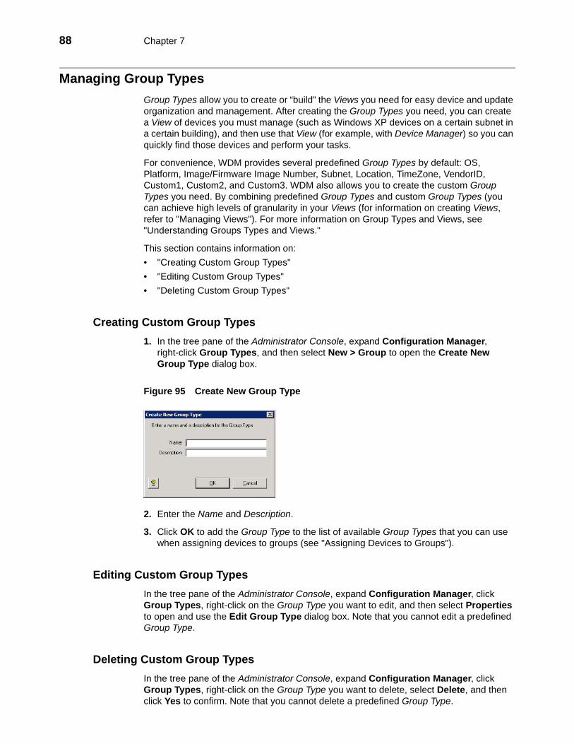
88 Chapter 7
Managing Group TypesGroup Types allow you to create or “build” the Views you need for easy device and update organization and management. After creating the Group Types you need, you can create a View of devices you must manage (such as Windows XP devices on a certain subnet in a certain building), and then use that View (for example, with Device Manager) so you can quickly find those devices and perform your tasks.
For convenience, WDM provides several predefined Group Types by default: OS, Platform, Image/Firmware Image Number, Subnet, Location, TimeZone, VendorID, Custom1, Custom2, and Custom3. WDM also allows you to create the custom Group Types you need. By combining predefined Group Types and custom Group Types (you can achieve high levels of granularity in your Views (for information on creating Views, refer to "Managing Views"). For more information on Group Types and Views, see "Understanding Groups Types and Views."
This section contains information on:• "Creating Custom Group Types"• "Editing Custom Group Types"• "Deleting Custom Group Types"
Creating Custom Group Types 1. In the tree pane of the Administrator Console, expand Configuration Manager,
right-click Group Types, and then select New > Group to open the Create New Group Type dialog box.
Figure 95 Create New Group Type
2. Enter the Name and Description.
3. Click OK to add the Group Type to the list of available Group Types that you can use when assigning devices to groups (see "Assigning Devices to Groups").
Editing Custom Group Types In the tree pane of the Administrator Console, expand Configuration Manager, click Group Types, right-click on the Group Type you want to edit, and then select Properties to open and use the Edit Group Type dialog box. Note that you cannot edit a predefined Group Type.
Deleting Custom Group TypesIn the tree pane of the Administrator Console, expand Configuration Manager, click Group Types, right-click on the Group Type you want to delete, select Delete, and then click Yes to confirm. Note that you cannot delete a predefined Group Type.

Configuration Manager 89
Managing Views WDM Views allow you to visually organize or “filter” your devices functionally so that you can more easily manage them. Views consist of hierarchies of folder groups, whether the folders are for a Group Type (predefined and/or custom), a Group Instance (within a Group Type), or any combination of these items. For more information on Group Types and Views, see "Understanding Groups Types and Views."
This section contains information on:• "Creating Views"• "Editing Views"• "Deleting Views"• "Using Advanced View Configuration Options"
Creating Views
TipBe sure you have created the Group Types you need to create or “build” the Views you want (see "Managing Group Types").
1. In the tree pane of the Administrator Console, expand Configuration Manager, right-click View, and then select New > View to open the Create New View dialog box.
Figure 96 Create New View
2. Use the following guidelines when creating the View:• Enter a Name for the View (so you can easily recognize it later).• Select a Group Type you want in the Available Groups list you want, and then add it
(click Add, double-click it, or drag-and-drop it to the position you want) to the Group Type Hierarchy pane (you can also use the Create New, Edit Group, and Delete Group command buttons as needed for convenience - see "Managing Group Types").
• You can continue to select the Group Types in the Available Groups list you want to add to the View (up to 30 levels).
• When adding Group Types to the View, you can select an item in the Group Type Hierarchy list and use the Remove, Move Up, and Move Down command buttons as needed to build the Group Type Hierarchy you want for the View.
90 Chapter 7
• To have the current View you are building automatically displayed as the default view when you click on Device Manager in the tree pane of the Administrator Console, select the Use as Current Device Manager View check box. Any previous default view will be replaced by this new default view (and moved to the Select Current Manager View list you can use when switching views).
• To have the current View you are building automatically selected during the update creation process (and displayed as the default view when you click on Update Manager in the tree pane of the Administrator Console—the default while viewing the scheduled WDM packages), select the Use as Current Update Manager View check box. Any previous default view will be replaced by this new default view (and moved to the Select Current Manager View list you can use when switching views).
• To have the current View you are building available only to you, the current user, select the Private View check box. Clear the check box (the default) to make the view available to all administrators authorized to use WDM.
TipYou can also use the Advanced Configuration command button to make further configurations as described in "Using Advanced View Configuration Options."
3. After you have finished configuring the View you want, click OK to add the View to the available Views that you can use.
Editing Views In the tree pane of the Administrator Console, expand Configuration Manager, click Views, right-click on the View you want to edit, and then select Properties to open and use the Edit View dialog box.
Deleting ViewsIn the tree pane of the Administrator Console, expand Configuration Manager, click Views, right-click on the View you want to delete, select Delete, and then click Yes to confirm.
TipYou cannot delete a View that is currently in use with either the Device Manager or Update Manager (you must switch to a different View before you can delete it).

Configuration Manager 91
Using Advanced View Configuration OptionsAdministrators can use the Advanced View Configuration options (Assign View Permissions and View Filter Criteria) for easier user and device administration with Views.
1. In the tree pane of the Administrator Console, expand Configuration Manager, click Views, right-click on a View you want to further configure with the Advanced View Configuration options, and then select Advanced Filter to open and use the Advanced View Configuration dialog box.
Figure 97 Advanced View Configuration
2. Use the following guidelines:• To give permissions to access the selected View to different users, select the users
in the Available list that you want, and then use the command buttons (or double-click them) to assign the users to the Selected pane (use All to assign all available users).
• To assign filter criteria for each or any of the Groups Types in the Group Type Hierarchy of the View, select a Group you want in the Select a Group list to display the Group Selections available for that Group, select the item in the Group Selections list you want to include in the filter criteria for the View, and then add it (click Add or double-click them) to the Filter Criteria pane (use Clear or Clear All as needed to remove selection).
3. After selecting the Advanced View Configuration options you want, click OK.

92 Chapter 7
Managing Default Device ConfigurationsThe Default Device Configuration (DDC) functionality allows you to configure default configurations for a group of devices. This functionality ensures that the device conforms to your configurations from a configuration perspective. If there is any deviation from your default configurations, WDM will revert the device back to your specified configurations. This feature automates the recovery of failed devices, the re-purposing of existing devices, and the addition of new devices within an existing infrastructure.
CautionBefore creating and assigning a DDC to update devices automatically, you must register the appropriate WDM packages that contain the settings, applications, or image updates you want to assign as a DDC. You must also select the Enable Default Device Configuration option in the Default Device Configuration dialog box, as discussed in "Device Manager Preferences."
This section contains information on:• "Creating and Assigning Default Device Configurations"• "Editing Default Device Configurations"• "Deleting Default Device Configurations"• "Viewing the Summary of a Default Device Configuration"
Creating and Assigning Default Device Configurations1. In the tree pane of the Administrator Console, expand Configuration Manager,
right-click Default Device Configuration, and select New > Default Device Configuration to open the Default Device Configuration Wizard.
Figure 98 Default Device Configuration Wizard—Primary Definition tab
2. Use the following guidelines for the Primary Definition tab:• Select A View For Adding A DDC - Select the View that includes the groups of the
devices to which you intend to assign the DDC. After you select a View, the View Hierarchy pane shows the various groups and levels of that View (you can use Expand All Items to display all levels in your View). In the View Hierarchy pane, select the group folder that contains the devices to which you want to assign the DDC.
• Operating System - Select the operating system of the devices to which you want to assign the DDC.

Configuration Manager 93
• Media Size - Enter the media size (in MBs) of the devices to which you want to assign the DDC. The WDM script package file for any WDM packages to be used in a DDC must specify the media size value of the intended target devices in the imagesize parameter under the [Version] section of script (for example, Imagesize=32). For more information on scripts, refer to "WDM ScriptBuilder Tool and Scripting Language."
TipFor ThreadX devices the Media Size must be 0.
• Qualifying OS Image - Select the image associated with the OS you want to form the basis for the DDC that you want to assign (selecting an image is no longer mandatory, you can select No Image from the list to avoid imaging; simply select the settings and other add-ons without selecting an image). If you do select an image, he image package must be named to correspond with the image number displayed by the Device Manager.
• Remove - The Remove button removes the image associated with the group in a DDC. Use this button to remove the group from the DDC definition.
TipYou can assign different images and packages to different View folders.
• Enforce Sequence - Depending on whether or not you want the WDM packages that are a part of the DDC to be the only packages allowed for the devices (that is no other packages can be sent to the devices), select or clear Enforce Sequence.
CautionSelecting Enforce Sequence may interfere with any WDM packages that are sent or scheduled to a device outside the DDC process.
3. After configuring your settings, click Next to open the Software Packages tab.
Figure 99 Default Device Configuration Wizard—Software Packages tab
4. Select the WDM packages in the Available For Selection list that you want to include in the DDC and click Add to move them to the Selected list.
TipUse Add and Remove to move as many packages as you want to (and from) the Selected list. Use Select/De-Select All to select or clear all package check boxes in the Available For Selection list or the Selected list. Use Move

94 Chapter 7
UP and Move Down to change the order of the WDM packages in the Selected list. When you move the mouse over the listed software packages, tooltips displays a description of the corresponding package.
5. (Optional) To add different OS images and software packages to specific groups within your view, you can return to the Primary Definition tab and complete steps 2 through 4 for each group you want.
6. After configuring your settings, click Next to open the Options tab.
Figure 100 Default Device Configuration Wizard—Options tab
7. se the following guidelines for the Primary Definition tab:• Execute DDC:
Select either the Whenever a device checks in option or the Each day at the time specified option for DDC execution (if you select the Each day at the time specified option, be sure to enter or select the time you want).
• Options: Select the Preserve Data Partition check box if you want to preserve any existing custom data partition you have on the client (outside of the partition used by the firmware).
• Select the Use Non PXE option if you are imaging using Non-PXE.
TipThe Preserve Data Partition option is only available for use with clients using multiple data partitions totalling 4 GB or larger, allowing you to remove the partition used for custom data that is not write filter protected (this is the custom data partition outside of the partition used for write filter protected firmware).
8. After configuring your settings, click Next to open the Summary tab.

Configuration Manager 95
Figure 101 Default Device Configuration Wizard—Summary tab
9. View the Summary tab to ensure that you have configured the DDC the way you want (if not, use Back and make your changes), and then click Finish to open the details pane displaying the newly assigned DDC.
The DDC is identified by its Operating System and Media Size. The next time a device from the View you specified checks-in or is discovered, and meets the Operating System and Media Size criteria, it will automatically be assigned the DDC.
TipFor information on viewing the Summary of a DDC in your WDM system, see "Viewing the Summary of a Default Device Configuration."
Editing Default Device Configurations In the tree pane of the Administrator Console, expand Configuration Manager, click Default Device Configuration, right-click on the DDC you want to edit, and then select Properties to open and use the Edit Default Device Configuration dialog box.
Deleting Default Device Configurations In the tree pane of the Administrator Console, expand Configuration Manager, click Default Device Configuration, right-click on the DDC you want to delete, select Delete, and then click Yes to confirm.
Viewing the Summary of a Default Device Configuration1. In the tree pane of the Administrator Console, expand Configuration Manager and
select Default Device Configuration, to display your existing DDCs.
2. Right-click the DDC for which you want to see the summary and select DDC Summary.

96 Chapter 7
Figure 102 Select DDC Summary Option
3. The Summary page for the specific DDC appears:
Figure 103 DDC Summary

Configuration Manager 97
Managing Licenses and CertificatesWDM allows you to easily manage licenses (see "Managing WDM Sales Keys") and certificates.
For information on licensing requirements for your WDM installation, see "Licensing and Sales Keys."
For information on tracking certificate expirations, see "Using the Certificate Expiration Tracker."
Managing WDM Sales KeysWDM allows you to view, add, upgrade, and delete Sales Keys as needed.
This section contains information on:• "Viewing Sales Key Details"• "Adding Sales Keys"• "Upgrading to an Enterprise Sales Key"• "Deleting WDM Sales Keys"
Viewing Sales Key DetailsIn the tree pane of the Administrator Console, expand Configuration Manager, click Licensing, right-click on the Sales Key you want to view, and then select Properties to display the license details.
Adding Sales Keys1. In the tree pane of the Administrator Console, expand Configuration Manager,
right-click Licensing, and select New > License to open the License Wizard.
Figure 104 Add License Wizard
2. Enter (or copy-and-paste) the Sales Key for the license you want to add, and click Next to open the success page.
3. Click Finish to open the Licensing details pane displaying your new Non-activated WDM Sales Key.
4. Activate this Sales Key by completing the procedures in "Activating Your Sales Key."

98 Chapter 7
Upgrading to an Enterprise Sales Key1. In the tree pane of the Administrator Console, expand Configuration Manager,
right-click Licensing, and select New > License to open the License Wizard.
Figure 105 Upgrade License Wizard
2. Enter (or copy-and-paste) the WDM Enterprise Sales Key for the license you want to add, and click Next.
3. Click Yes to confirm and start the license upgrade. After the upgrade is complete, the Licensing details pane displays your new Non-activated WDM Enterprise Sales Key.
4. Activate this Enterprise Sales Key by completing the procedures in "Activating Your Sales Key."
Deleting WDM Sales KeysIn the tree pane of the Administrator Console, expand Configuration Manager, click Licensing, right-click on the Sales Key you want to delete, select Delete, and then click Yes to confirm.
TipYou cannot delete the last remaining WDM Sales Key.

Configuration Manager 99
Configuring Preferences1. In the tree pane of the Administrator Console, expand Configuration Manager, and
then click Preferences to display the list of preferences available in the details pane.
2. Double-click the name of the preference you want to configure to open and use the Preferences dialog box.
3. Depending on the preferences you want to configure, refer to the following:• "Device Manager Preferences"• "Logging Preferences"• "Service Preferences"• "DHCP/TFTP Preferences"• "Scheduling Preferences"• "Subnet Preferences"• "Wyse Thin OS Preferences"
Device Manager PreferencesDouble-clicking Device Manager in the list of preferences opens the Device Manager Preferences dialog box.
Figure 106 Device Manager Preferences
Use the following guidelines:• Web Service Check-In Preferences area:
· Perform a partial check-in every - Set the partial check-in frequency of all devices by selecting a number and a time unit (minutes, hours, days). The default is 1 Hour. Partial check-ins occur regularly at the specified interval to ascertain device health status (red, yellow, green). Partial check-ins require less network bandwidth than a full check-in (important for large WDM installations with thousands of devices). Changes to check-in frequencies will not take effect until after the previously set check-in time or if devices are refreshed.
· Missed Check-ins for Yellow Icon - Select the number of missed check-ins before the icon for the device turns yellow to indicate there might be a problem with the device.

100 Chapter 7
· Missed Check-ins for Red Icon - Select the number of missed check-ins before the icon for the device turns red to indicate there might be a serious problem with the device.
• Auto Agent Upgrade Preferences area:· Automatically Upgrade Older Agents - Select to enable Auto-Agent Upgrades of
WDM Agents, and then select an option: Now - to upgrade older Agents at the time WDM discovers the Agent; or Clock - to set a time at which WDM will update older versions of WDM Agents after discovering them (preferably, this should be a time of low network activity to avoid overloading your network with Agent upgrade transactions).
· Full Check-In After Update - Select to cause a device to check-in with the Web Service after the device receives and executes the files in a WDM package.
· Show Empty Custom Group Folders - Select if you want to display any empty folders in the Device Manager when you create custom Group Types for your Views (for information on the effects this option on device organization, see "Understanding the Show Empty Custom Group Folders Option").
· Device(s) / Page - Select the number of devices to display on the Devices page.• GUI Discovery Preferences area:
· Maximum number of ranges to discover - Enter the maximum number of ranges you want to discover.
• Socket Family Preference - Select the option you want (IPV4, Dual Stack, or IPV6).
Clicking DDC (Default Device Configuration) in the Device Manager tree opens the Default Device Configuration dialog box.
Figure 107 Default Device Configuration
Use the following guidelines:• Enable Default Device Configuration - (WDM Enterprise Edition Only) Select to
allow devices to use DDCs for automatic upgrades (see "Managing Default Device Configurations").
• Time to Schedule DDC Reconciliation area - Select an option: Upon Check-in - if you want the DDC to occur when a device checks-in with the Web Service; or a custom time - to specify the time of the day after which you want the DDC to occur (note that this is not the actual time when a DDC is reconciled, as the actual time will depend on the frequency of check-ins you set in the Device Manager Preferences dialog box).

Configuration Manager 101
Logging PreferencesClicking Logging Preferences in the list of preferences opens the Logging Preferences dialog box.
Figure 108 Logging Preferences
Use the following guidelines:• Logging Services area - Select the logging level for each of the communication
protocols. Options include:· Errors - Consisting of simple error messages.· Warning - Consisting of warnings in addition to error messages (this is the default
option).· Informational - Consisting of other information items in addition to error and
warning messages.· Debug - Consisting of all information in Errors, Warning, Informational, and
additional debugging data that might be useful for troubleshooting.• Write Preferences changes to system log - Select to keep logging level changes in
the system log table.• Auto Archiving Log Services area - Configure the size of the system log table and
warning message frequency: · Maximum Line Count in SystemLog Table - Enter the number of records allowed
before archiving occurs; valid values are from 500000 to 10000000; the default value is 10000000).
· Number of Log Entries to Truncate - Enter the number of records to be archived; valid values depend upon the Maximum Line Count in SystemLog Table configured; if the maximum line count value is 5000, valid values for log entries to truncate are from 500 to 4999. If the maximum line count is set to 10000000, the valid values for log entries to truncate are from 500 - 999999).
TipThe value for the Number of Log Entries to Truncate is always less than the value for the Maximum Line Count in SystemLog Table.
• Log Archive Warning message on every - Edit the time interval for displaying the circular logging warning message (default interval is every 5 hours). When the value you set for the Maximum Line Count in SystemLog Table is exceeded, the Archive Logs warning message appears. The first time the line count exceeds the configured limit, a warning message appears immediately. If you select OK, the System Log Archive window appears (if you select Cancel, you will see the warning again at the next configured warning message interval).

102 Chapter 7
Figure 109 System Log Archive window
Use the options and list menus to select the logs to be archived, the output file format, and output file location. After configuring, click Archive.
Clicking Logging Details in the Logging Levels tree opens the Logging Details Preferences dialog box where you can make further selections.
Figure 110 Logging Details Preferences
TipCategory Status Changes refers to whether a WDM package changed from one category to another (for example, if you edit the script file for a WDM package and change it from Image to Client Configuration), while Package Status Changes refers to whether a package changes from active to inactive or inactive to active.

Configuration Manager 103
Service PreferencesDouble-clicking Service Preferences in the list of preferences opens the Service Preferences dialog box. Use this dialog box to set global service preferences and repository communication preferences.
Figure 111 Service Preferences
Use the following guidelines:• Time Out Preferences area - Select the Connect (Millisecs) (number of milliseconds
in which WDM will attempt to connect to a device, whether through the Web Service or the Standard Service, before timing out) and the Discovery (Secs) (maximum time allotment for WDM to discover all of the devices in your network).
• Wake On LAN Preferences area - Select the Wake On LAN tries (number of times that the service attempts to perform a WOL command before stopping) and the Delay between WOL tries (Secs) (length of time WDM pauses before it attempts another WOL command to the same device).
• Port for CE OS and Port for Other OS - Enter the ports you need.• Enable Legacy Agent Service - Select option to communicate with older versions of
WDM Agents.• Enable WDM Service Logs - Select option to start or stop the service log during WDM
start up.• Enable ThreadX Service Polling - Select option to poll ThreadX devices.• Repository Preferences area - Select HTTP, FTP, or both for the transfer protocol.
The Repository Preferences settings will determine the protocol (HTTP or FTP) that is used to communicate with a Repository during WDM package registration, WDM package deletion, Remote Software Repository Synchronization (WDM Enterprise Edition Only), and WDM package updates for client devices.
TipThis is a global option that applies only when the WDM Administrator Console is started. To start or stop the service logs for a particular session, right-click Wyse Device Manager to open and use the stop or start service log toggle option (shown in Figures 112 and 113) to start or stop the service log.
CautionThe Master Software Repository must support the protocols selected in the Repository Preferences. For details about the way Repository Preferences for WDM package registration and WDM package updates affect client devices, see Tables 10-1 and 10-2.

104 Chapter 7
Figure 112 Start Service Log
Figure 113 Stop Service Log
Table 5 Protocol Used to Register WDM Packages to Master Software Repository
Global Repository Preference Setting
Master Repository Preference Setting WDM Transfer Protocol
HTTP HTTP(S) HTTP(S) only
FTP FTP FTP only
FTP HTTP(S) and FTP FTP only
HTTP and FTP HTTP(S) and FTP HTTP(S) is attempted and used if successful; if it fails, FTP is used.
Table 6 Protocol Used for WDM Package Updates
Global Repository Preference Setting
Preference Setting for Repository Used by Client Protocol Used to Transfer Package
HTTP FTP HAgent on client device uses Master HTTP(S) repository only
HTTP HTTP(S) and FTP HAgent on client device uses assigned HTTP(S) repository only
FTP FTP HAgent on client device uses assigned FTP repository only
FTP HTTP(S) HAgent on client device uses Master FTP repository only
FTP HTTP(S) and FTP HAgent on client device uses assigned FTP repository only
HTTP and FTP HTTP(S) HAgent on client device uses assigned HTTP(S) repository only

Configuration Manager 105
• Click Port Settings in the Service tree to open the Port Settings Preferences dialog box.
Figure 114 Port Settings Preferences
Use the following guidelines:• Port Preferences area:
· GUI Listening Port and Alternate GUI Listening Port Range - Port(s) through which the Web Service listens for incoming WDM Agent requests.
· Standard Service Listening Port - Port through which the Standard Services listens for device check-in activity.
· Web Server HTTP Port - Port WDM uses to issue real-time commands (such as Quick Device Commands or device updates at a specific time). Normally this is port 80. Note that you can change this port only through your Web Server.
· Web Server HTTPS Port - (WDM Enterprise Edition Only): Port WDM uses to issue real-time commands (such as Quick Device Commands or device updates at a specific time). Normally this is port 443. Note that you can change this port only through your Web Server.
CautionThe configured port, either HTTP or HTTPS, determines the communication protocol between the components of WDM.
· ThreadX Service Port - Port WDM uses to issue real-time commands (such as Quick Device Commands or device updates at a specific time). Normally this is port 9880. Note that you can change this port only through your Web Server.
HTTP and FTP FTP HAgent on client device uses assigned FTP repository only
HTTP and FTP HTTP(S) and FTP HAgent on client device tests connection for assigned HTTP(S) repository and if successful, uses assigned repository via HTTP(S). If the connection fails, HAgent uses assigned repository via FTP.
Table 6 Protocol Used for WDM Package Updates, Continued
Global Repository Preference Setting
Preference Setting for Repository Used by Client Protocol Used to Transfer Package

106 Chapter 7
· Secure Communications - (WDM Enterprise Edition Only): This is a read-only box that indicates the communication between the components of WDM (as well as devices) is secure (selected) or not secure (cleared).
• Use Host - Use Host can be selected (enabled) to have the HAgent use the Server Host Name you enter to connect to the server. Note that the Server Host name will have a default value of the Host machine and an Administrator can change this value to a different host name (useful in cases of request forwarding through an HTTP Proxy).
DHCP/TFTP PreferencesDouble-clicking DHCP/TFTP Preferences in the list of preferences opens the DHCP/TFTP Preferences dialog box.
Figure 115 DHCP/TFTP Preferences
Use the following guidelines:• DHCP Proxy Preferences area:
· Start DHCP Proxy - Select to allow WDM to serve as a Dynamic Host Configuration Protocol (DHCP) proxy.
· Enable DHCP Options for HTTP Discovery - Select to allow the Web Service to use DHCP when discovering devices.
· Default Boot Image - Enter the name of the folder where the default boot images are kept. Typically, this is the Trivial File Transfer Protocol (TFTP) root directory below the FTP home directory used by the Master Repository.
• TFTP Server Preferences area: · Start TFTP - Select to allow WDM to use TFTP when updating devices.· TFTP Master Mount Point - Displays the TFTP mount point that WDM set during
installation. Typically, this is the TFTP root directory (WDM) below the FTP home directory used by the Master Repository.
· TFTP Time Out (Secs.) - Specify the length of time (in seconds) that WDM waits for a connection to the TFTP service before attempting to reconnect.
· TFTP Retries - Specify the number of times that WDM will attempt to connect to the TFTP service before failing.
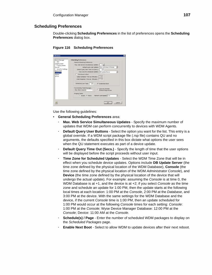
Configuration Manager 107
Scheduling Preferences Double-clicking Scheduling Preferences in the list of preferences opens the Scheduling Preferences dialog box.
Figure 116 Scheduling Preferences
Use the following guidelines:• General Scheduling Preferences area:
· Max. Web Service Simultaneous Updates - Specify the maximum number of updates that WDM can perform concurrently to devices with WDM Agents.
· Default Query User Buttons - Select the option you want for the list. This entry is a global override. If a WDM script package file (.rsp file) contains QU and no arguments, the defaults specified in this box dictate what options the user sees when the QU statement executes as part of a device update.
· Default Query Time Out (Secs.) - Specify the length of time that the user options will be displayed before the script proceeds without user input.
· Time Zone for Scheduled Updates - Select the WDM Time Zone that will be in effect when you schedule device updates. Options include DB Update Server (the time zone defined by the physical location of the WDM Database), Console (the time zone defined by the physical location of the WDM Administrator Console), and Device (the time zone defined by the physical location of the device that will undergo the actual update). For example: assuming the Console is at time 0, the WDM Database is at +1, and the device is at +2; if you select Console as the time zone and schedule an update for 1:00 PM, then the update starts at the following local times at each location: 1:00 PM at the Console, 2:00 PM at the Database, and 3:00 PM at the device. With the same settings for the WDM Database and the device, if the current Console time is 1:00 PM, then an update scheduled for 1:00 PM would occur at the following Console times for each setting: Console: 1:00 PM at the Console; Wyse Device Manager Database: 12:00 PM at the Console; Device: 11:00 AM at the Console.
· Schedule(s) / Page - Enter the number of scheduled WDM packages to display on the Scheduled Packages page.
· Enable Next Boot - Select to allow WDM to update devices after their next reboot.

108 Chapter 7
· Time Bound Rollout - Enables or disables the garbage collector feature for scheduled updates. When selected, the settings of the Global Schedule Time-out and the Client Response Time-out will determine whether the scheduled updates enter an error state or remain in the scheduled state indefinitely.· Global Schedule Time-out (Minutes) - Time period after which all the
outstanding scheduled updates will be moved to error state.· Client Response Time-out (Minutes) - Time period for which the WDM server
will wait for the client to check in after WDM has successfully sent the notification to the client.
• Auto-sync Remote Repositories (WDM Enterprise Edition Only) - Select to enable WDM to determine whether Remote Repositories should be synchronized before performing an update to devices served by a Remote Software Repository.
• Rescheduling Failed Packages area:· Max. Retry Count - Specify the maximum number of retries you want if WDM
package distribution fails.• Imaging Option area - Select one of two ways to image a device:
· WISard - Legacy method for imaging devices which requires PXE for imaging.· Merlin - Enables FTP, HTTP or HTTPS-based imaging for the devices.
Network Card Speed - (Merlin Imaging Only) Possible values are Auto, 100M-F (100 MBPS Full duplex), 100M-H (100 MBPS Half duplex).

Configuration Manager 109
Subnet PreferencesDouble-clicking Subnet in the list of preferences opens the Subnet Preferences dialog box.
Figure 117 Subnet Preferences
Use the following guidelines:• Show Subnet Hierarchy - (WDM Enterprise Edition Only) Select to allow any subnet
views to include the hierarchical view of the subnet.• Show Subnet Description in Hierarchy - (WDM Enterprise Edition Only) Select to
display hierarchical subnet views by the descriptions of the subnets rather than by their address. Note that the default description is always the subnet IP.
• Subnet Hierarchy Start Level - Specify the starting level for displaying subnet hierarchies. A level refers to one of the four octets in the subnet address.
• Subnet Hierarchy End Level - Specify the ending level for displaying subnet hierarchies. A level refers to one of the four octets in the subnet address.

110 Chapter 7
Wyse Thin OS PreferencesDouble-clicking WTOS in the list of preferences opens the WTOS Preferences dialog box.
Figure 118 Wyse Thin OS Preferences
Use the following guidelines:• Enable Return FTP/INI At Checkin - Select to allow WDM to use File Transfer
Protocol (FTP) when updating devices.• WTOS Root Path - Enter the Wyse ThinOS root path.

Configuration Manager 111
Understanding WDM RepositoriesA WDM Repository is a server which supports the FTP, HTTP, and HTTPS protocols for communication and contains WDM packages. When you register a WDM package using the Package Manager, WDM copies the related folders and files of the WDM package to a WDM Repository. There are two types of WDM repositories, Master and Remote. By default, each WDM installation has one Master Repository. The Master Repository is the central storage place for all WDM package files.
When you distribute an update, devices connect to the Master Repository through FTP, HTTP, or HTTPS (depending on the configuration settings) and download the files that the script file (.rsp file) of the package dictates. WDM and the WDM Agents use FTP, HTTP, or HTTPS to send and retrieve the appropriate WDM packages from the Master Repository.
In addition, WDM Enterprise Edition allows you to install remote repositories on multiple computers on different subnets throughout your network (see "WDM Enterprise Edition Only: Managing Software Repositories"). This scalability reduces network traffic when you need to send updates across subnets. By using their local Remote Software Repository, devices on a specific subnet do not need to access the Master Repository across a wide-area network (WAN) to retrieve files (WDM synchronizes the Master and Remote software repositories prior to a WDM package distribution).
If your WDM installation contains Remote Software Repositories, WDM must establish the relationship between a given set of devices and the Remote Software Repository that services those devices (thereby ensuring lower network loads). After establishing this relationship, WDM is able to select the appropriate repository when distributing packages to devices. Devices are associated to a Remote Software Repository by the subnet to which they belong. After you assign a subnet to a repository, all devices on that subnet will use the assigned repository.
WDM Enterprise Edition Only: Managing Software RepositoriesWDM Enterprise Edition allows you to install multiple repositories on your network (for repository installation procedures, see Installation Guide: Wyse Device ManagerTM). Remote Software Repositories help save network bandwidth because they store and distribute software updates locally to devices that reside in the same subnet as each repository.
Be aware that:• WDM always names the first repository you install Master. Any additional Remote
Software Repositories that you install can be named anything other than Master. The user IDs and passwords for all repositories can be the same for FTP-based repositories, but must be different for HTTP-based repositories.
• If you do not install multiple Remote Software Repositories, then WDM uses the Master Repository for all subnets.
• If you deployed WDM components separately, then it is recommended that you install the Master Repository on a machine on the same subnet as where you installed the other WDM components.
• There are two possible repository authentications: · Basic Authentication - This authentication mode requires you to enter a valid NT
login and password to gain access to the system. When Basic Authentication is enabled, you will be prompted for your username and password when you attempt to access the virtual directory. The password is sent in Clear Text.
· Integrated Windows Authentication - This is the most secure form of authentication in IIS. When you login, NT validates your login and only your username is

112 Chapter 7
transmitted over the network. No password is transmitted, so your password cannot be compromised.
This section contains information on:• "Registering Remote Software Repositories"• "Editing Software Repositories"• "Deleting Software Repositories"
Registering Remote Software RepositoriesAfter installing an additional Remote Software Repository, you must register it in the WDM Database and then assign the Remote Software Repository to a subnet.
TipFor information on assigning a Software Repository to a subnet, see "Managing Subnets."
1. In the tree pane of the Administrator Console, expand Configuration Manager, right-click Software Repositories and select New > Software Repository to open the Software Repository dialog box.
Figure 119 Software Repository
2. Use the following guidelines:• Name - Displays the descriptive name for the Remote Software Repository you
entered during installation. • Connection Information area:
· Location - IP address to identify the Remote Software Repository.

Configuration Manager 113
· Transfer Type - Type of transfer protocol that is in use (see "Service Preferences"). Options are FTP, HTTP, or both
· Relative Path - Relative path from the FTP root folder.• FTP area:
· User/Group Name - User name for the FTP account as set up by IIS FTP or the FTP service that you use to connect to the repository.
· Password - FTP password as set up by IIS FTP or the FTP service that you use to connect to the repository.
· Verification - Retype the password to verify you entered it correctly.· Port Number - Port number for FTP communication. The default port number
for FTP is 21.· Session Timeout - Time in seconds that the connection for each session should
remain open.· Bandwidth - How much bandwidth in Kbps to utilize for data transfer to and
from the Software Repository.• HTTP area:
· User/Group Name - Strongly recommended if Basic Authentication or Windows Integrated Authentication is used for the software repository, but this box is not mandatory.
· Context - Virtual directory path for HTTP communication. This box is disabled if the selected transfer type is FTP only.
· Password - Strongly recommended if Basic Authentication or Integrated Windows Authentication is used for the software repository; however, this box is not mandatory.
· Port Number - Port number for HTTP communication. The default port number for HTTP is 80, and for HTTPS is 443.
· Verification - Password verification for HTTP user.· Timeout - Time in seconds that the connection for each session should remain
open.· Secure (HTTPS) - If checked, the HTTP communication for the repository is
secure.· Validate Certificate with CA - If checked, the Certificate validation for HTTPS
communication is enabled.· Read Only - If checked, there is only permission to read from the repository
(there is no write permission to the repository).
3. Click OK. WDM will test the connection to the Remote Software Repository that you registered to ensure that it is properly configured (you can test the connection to a Remote Software Repository at any time by right-clicking the Remote Software Repository name and selecting Test Connection). The new Remote Software Repository is now successfully set up and registered in the WDM Database. You can now assign the Remote Software Repository to a subnet (see "Managing Subnets").
TipWDM stores every package that you register in its Master Repository. You can synchronize Remote Software Repositories whenever you perform an update for a device on a subnet that has access to a local repository. Table 7 shows the protocol that will be used for synchronization, based on the protocol settings for the Master Repository and Remote Software Repository. For more information on Remote Software Repository synchronizations, see "WDM Enterprise Edition Only: Scheduling a Remote Repository Synchronization."

114 Chapter 7
Editing Software RepositoriesIn the tree pane of the Administrator Console, expand Configuration Manager, click Software Repositories, right-click on the Software Repository you want to edit, and then select Properties to open and use the Edit Software Repository dialog box.
Deleting Software Repositories In the tree pane of the Administrator Console, expand Configuration Manager, click Software Repositories, right-click on the Software Repository you want to delete, select Delete, and then click Yes to confirm.
Table 7 Protocol Used for Remote Software Repository Synchronization
Master Repository Preference Setting
Remote Software Repository Preference Setting
Synchronization Protocol
HTTP HTTP(S) HTTP(S) only
HTTP FTP Error - no synchronization
HTTP HTTP and FTP HTTP only
FTP HTTP(S) Error - no synchronization
FTP FTP only FTP only
FTP HTTP(S) and FTP FTP only
HTTP and FTP HTTP(S) HTTP(S) only
HTTP and FTP FTP FTP only
HTTP and FTP HTTP(S) and FTP HTTP(S) is attempted and used if successful; if it fails, FTP is used

Configuration Manager 115
Managing NetworksManaging Networks includes:• "Managing Subnets"• "Managing IP Ranges"
Managing SubnetsWDM uses subnet information to discover and communicate with the devices on your network.
TipAlthough you can add subnets to WDM manually, you can also use a WDM utility to import subnet data from comma-delimited and tab-delimited files into the Database (see "Importing Subnet Data from Files").
This section contains information on:• "Adding Subnets to WDM Manually"• "Editing Subnets"• "Deleting Subnets"
Adding Subnets to WDM Manually1. In the tree pane of the Administrator Console, expand Configuration Manager,
expand Networks, right-click Subnets, and then select New > Subnet to open the Subnet dialog box.
Figure 120 Subnet
2. Complete one of the following:• If you want to provide a broadcast address for the subnet manually, select
Manually create and enter the Broadcast Address.• If you do not want to provide a broadcast address for the subnet manually, enter the
IP Address (Type a valid IP address from the subnet), Subnet Mask (Type the subnet mask for the subnet), and # of Contiguous Bits (if your network uses Classless Inter-Domain Routing or supernetting, type the number of contiguous bits to configure your subnet mask).

116 Chapter 7
3. Enter a Description to identify the subnet in the WDM Database.
4. Select the Software Repository. If your WDM configuration includes multiple Remote Software Repositories and you want to associate the subnet with one of them, select it in the Software Repository list.
TipWhen distributing WDM packages to a group of devices, WDM uses the subnet/repository association to determine the appropriate Remote Software Repository for the devices.
5. (Optional) If you want to associate newly discovered devices on this subnet with a user-defined Group Type (WDM always assigns devices to the predefined Group Types according to the values found on the devices), select the row for the Group Type you want from the Default Groups pane to open and use the Default Group Value dialog box (select the Default Value in the Default Group Value dialog box and click OK to return to the Subnet dialog box). Be aware that to associate devices in a subnet with a Group Type, you must have previously created the desired Group Types.
6. Complete one of the following:• If you do not want to override the global preferences for this subnet, click OK. • (WDM Enterprise Edition Only) If you want to override the global preferences for
this subnet, select Override Global Preferences, complete the subnet preferences using the following guidelines, and then click OK:· Maximum Simultaneous Updates - Maximum number of device updates you
can perform at the same time in the subnet.· Wake On LAN Time Out (Secs.) - Length of time WDM attempts to wake a
device on the subnet before stopping.· Wake On LAN Retries - Number of times WDM attempts to wake a device in
the subnet before stopping.· TFTP Time Out (Secs.) - Length of time WDM attempts to use the Trivial File
Transfer Protocol (TFTP) to communicate with devices during PXE operations.· TFTP Retries - Number of times WDM attempts to use TFTP before stopping.· Network Card Speed - This box is valid only for Merlin imaging. The possible
values are Auto, 100M-F (100 MBPS Full duplex), 100M-H (100 MBPS Half duplex).
The information about the subnet and its preferences are now stored in the WDM Database and WDM can discover the devices on the subnet.
Editing SubnetsIn the tree pane of the Administrator Console, expand Configuration Manager, expand Networks, click Subnets, right-click on the Subnet you want to edit, and then select Properties to open and use the Edit Subnet dialog box.
Deleting SubnetsIn the tree pane of the Administrator Console, expand Configuration Manager, expand Networks, click Subnets, right-click on the Subnet you want to delete, select Delete, and then click Yes to confirm.

Configuration Manager 117
Managing IP RangesIP Ranges allow WDM to discover devices with all supported versions of WDM Agents through a Transmission Control Protocol (TCP) connection to each device in an IP Range rather than through a User Datagram Protocol (UDP) broadcast to an entire subnet level.
TipAlthough you can add IP ranges to WDM manually, you can also use a WDM utility to import IP Range data from comma-delimited and tab-delimited files into the Database (see "Importing IP Range Data from Files").
This section contains information on:• "Adding IP Ranges to WDM Manually"• "Editing IP Ranges"• "Deleting IP Ranges"
Adding IP Ranges to WDM Manually1. In the tree pane of the Administrator Console, expand Configuration Manager,
expand Networks, right-click IP Ranges, and then select New > IP Range to open the IP Range dialog box.
Figure 121 IP Range
2. Use the following guidelines:• Start IP Address - Starting IP address for the IP Range.• End IP Address - Ending IP address for the IP Range.• Exclude From - Beginning IP address for the range of addresses to exclude from
the range you are setting up (for example, if you wanted to exclude devices from 192.168.1.30 onward then you would enter 192.168.1.30).
• Exclude To - Ending IP address for the range of addresses to exclude from the range you are setting up (for example, if you wanted to exclude devices up to 192.168.1.35 then you would enter 192.168.1.35).
• Description - Type a brief description to identify the IP Range.
3. Click Add to store information about the IP Range in the WDM Database. WDM can now selectively discover devices in a subnet through a TCP connection to each device.

118 Chapter 7
Editing IP RangesIn the tree pane of the Administrator Console, expand Configuration Manager, expand Networks, click IP Ranges, right-click on the IP Range you want to edit, and then select Properties to open and use the Edit IP Range dialog box.
Deleting IP RangesIn the tree pane of the Administrator Console, expand Configuration Manager, expand Networks, click IP Ranges, right-click on the IP Range you want to delete, select Delete, and then click Yes to confirm.

Configuration Manager 119
Managing User PermissionsAs an administrator you can add, edit and delete WDM users. WDM allows you to manage users from local computer accounts or from Active Directory.
This section contains information on:• "Adding Users from Local Computer Accounts"• "Adding Users and Groups from Active Directory"• "Editing User Permissions"• "Deleting Users"
Adding Users from Local Computer Accounts
TipBefore you can add a WDM user, the user must already exist in the list of users for the Windows Domain where you installed WDM.
1. In the tree pane of the Administrator Console, expand Configuration Manager, right-click User Permissions, and select New > User to open the WDM Add User Utility dialog box.
Figure 122 WDM Add User Utility - Domain Search tab
2. On the Domain Search tab, select the name of the user you want to add as a WDM user and click Add.
3. Click OK to add the new user to the list of WDM users.
4. New users do not have permissions until you edit the user permissions; continue with "Editing User Permissions."

120 Chapter 7
Adding Users and Groups from Active Directory
TipBefore you can add a WDM group, the group must already exist in Active Directory.
1. In the tree pane of the Administrator Console, expand Configuration Manager, right-click User Permissions, and select New > User to open the WDM Add User Utility dialog box.
Figure 123 WDM Add User Utility - Active Directory Search tab
2. On the Active Directory Search tab, enter an IP Address/name or select a Domain Controller from the list (the server to which you installed Wyse Device Manager must be a part of the Domain).
3. Select the search criteria option you want (if you select Find A Specific User, be sure to enter the exact name of the user), and then click Search to view the search results.
4. After making your selections, click Add to integrate the users and groups with WDM.
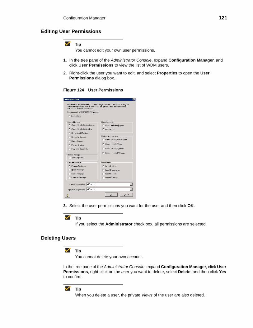
Configuration Manager 121
Editing User Permissions
TipYou cannot edit your own user permissions.
1. In the tree pane of the Administrator Console, expand Configuration Manager, and click User Permissions to view the list of WDM users.
2. Right-click the user you want to edit, and select Properties to open the User Permissions dialog box.
Figure 124 User Permissions
3. Select the user permissions you want for the user and then click OK.
TipIf you select the Administrator check box, all permissions are selected.
Deleting Users
TipYou cannot delete your own account.
In the tree pane of the Administrator Console, expand Configuration Manager, click User Permissions, right-click on the user you want to delete, select Delete, and then click Yes to confirm.
TipWhen you delete a user, the private Views of the user are also deleted.

122 Chapter 7
Using WDM UtilitiesWDM includes various utilities to help you with administration tasks.
This section contains information on:• "Importing IP Range Data from Files"• "Importing Subnet Data from Files"• "Importing Software Repository Data"• "Importing Device Settings Data from Files"
Importing IP Range Data from FilesWith WDM, you can import IP Range data from comma-delimited and tab-delimited files into the WDM Database.
TipFor the required format of Remote Software Repository flat files, see "Required Format for Importing IP Range Data from Files."
1. In the tree pane of the Administrator Console, expand Configuration Manager, expand Utilities, right-click Imports, and then select New > Import to open the Import Utility dialog box.
Figure 125 Import Utility - IP Ranges
2. Select the IP Ranges option, and enter (or browse for) the location of the data file in the Import Path and Filename box.
3. Click OK to import the IP Range data into the WDM Database (in the tree pane of the Administrator Console, you can expand Configuration Manager, expand Networks, and then select IP Ranges to view the newly imported remote IP Range data).

Configuration Manager 123
Required Format for Importing IP Range Data from FilesThe following example shows the required format for IP Range flat files:
StartIP, EndIP, ExclusionStartIP, ExclusionEndIP, Description
StartIP - Beginning IP address for IP range
EndIP - Ending IP address for IP range
ExclusionStartIP - Beginning IP address for IP exclusion range
ExclusionEndIP - Ending IP address for IP exclusion range
Description - Name of IP range that will appear in the Administrator Console
Example: 10.10.10.10,10.10.10.200,10.10.10.20,10.10.10.30, My IP Range
This IP Range definition will be added to the database to allow for IP Range walking discover on and discover all devices between the ranges of 10.10.10.10 to 10.10.10.19 and 10.10.10.31 to 10.10.10.200. This IP Range definition will display in the Administrator Console as My IP Range.
Importing Subnet Data from FilesWith WDM, you can import subnet data from comma-delimited and tab-delimited files into the WDM Database.
TipWDM Enterprise Edition Only: For Remote Software Repositories, your WDM Database must contain information about at least one Remote Software Repository before you can work with subnets (see "WDM Enterprise Edition Only: Managing Software Repositories").
TipFor the required format of Remote Software Repository flat files, see "Required Format for Importing Subnet Data from Files."
1. In the tree pane of the Administrator Console, expand Configuration Manager, expand Utilities, right-click Imports, and then select New > Import to open the Import Utility dialog box.
Figure 126 Import Utility - Subnets

124 Chapter 7
2. Select the Subnets option, and enter (or browse for) the location of the data file in the Import Path and Filename box.
3. Click OK to import the Subnet data into the WDM Database (in the tree pane of the Administrator Console, you can expand Configuration Manager, expand Networks, and then select Subnets to view the newly imported remote Subnet data).
Required Format for Importing Subnet Data from FilesThe following example shows the required format for subnet flat files:
Broadcast Address, Description, SW Repository, Override Default Parameters, IP Address, Subnet Mask, Max. Web Service Simultaneous Updates, Wake On LAN Time Out(Secs.), Wake On LAN Tries, TFTP Time Out(Secs.), TFTP Retries, Network Card Speed
Broadcast Address - Broadcast address; example: 10.10.10.255
Description - Name of Subnet that will appear in the Administrator Console
SW Rep - Name of a Software Repository. You can not add a Subnet without a Software Repository. The name of the master Repository ID is MASTER.
Override Default Parameters - Override Global Preferences (Enterprise Only).
IP Address - Valid IP address in subnet; example: 199.199.10.2.
Subnet Mask - Subnet mask; example: 255.255.255.0
Max. Web Service Simultaneous Updates - Maximum Simultaneous Updates; example: 5
Wake On LAN Time Out(Secs.) -Time Out for Wake On LAN; example: 2
Wake On LAN Tries - WOL Retry; example: 3
TFTP Time Out(Secs.) - TFTP Timeout; example: 10
TFTP Retries - TFTP Retries; example: 3
Network Card Speed - Network Card Speed; example: 1 (for Auto), 2(for 100M-F), 3(for 100M-H)
Example: 10.10.10.255,Subnet1,MASTER,False,199.199.10.2,255.255.255.0,6,2,1,1,7,2
This will add to the database a subnet definition that will discover and manage devices on a subnet with IP address assignments from 199.10.0.1 to 199.10.0.254. The column header either does not exist or exists in the above proper order.

Configuration Manager 125
Importing Software Repository DataWith WDM, you can import Remote Software Repository data from comma-delimited and tab-delimited files into the WDM Database.
TipFor the required format of Remote Software Repository flat files, see "Required Format for Importing Software Repository Data from Files."
1. In the tree pane of the Administrator Console, expand Configuration Manager, expand Utilities, right-click Imports, and then select New > Import to open the Import Utility dialog box.
Figure 127 Import Utility - Software Repositories
2. Select the Software Repository option, and enter (or browse for) the location of the data file in the Import Path and Filename box.
3. Click OK to import the Software Repository data into the WDM Database (in the tree pane of the Administrator Console, you can expand Configuration Manager, and then select Software Repository to view the newly imported remote Software Repository data).
TipWhen you register a new software repository, WDM establishes a connection to ensure that it can communicate with the Remote Software Repository. When you import repository data, WDM tests the connection to the repository automatically. Therefore, after you import data one or more Remote Software Repository, you do not need to test the connection.

126 Chapter 7
Required Format for Importing Software Repository Data from FilesThis example shows the required format for Remote Software Repository flat files:
Name of Rep,IP Address of Repository,TransferType,RelPath,Context,FTPPortNumber,HTTPPortNumber,FTP UserName,FTP Password,HTTP UserName,HTTP Password,IsHTTPSecure,HTTPSValidateWithCA
Name - Name of the Remote Software Repository as it appears in the Administrator Console
Location - IP address of the FTP server
Transfer Type - Type of transfer protocol in use. Options are: FTP, HTTP or both.
Relative Path - Path to the software repository relative to the root directory. The default value for this is /rapport.
Context - This is valid for HTTP communication and is the name of the virtual directory. The default name for the HTTP context is MyWDM.
FTP Port Number - Port number for FTP communication. The default port number is 21.
HTTP Port Number - Port number for HTTP or HTTPS communication. The default port number for HTTP is 80. The default port for HTTPS communication is 443.
FTP User Name - User name for the FTP account as set up by IIS FTP or the FTP service that you use to connect the repository
FTP Password - Password for the FTP account as set up by IIS FTP or the FTP service that you use to connect the repository
HTTP User Name - User name for the HTTP account as set up by IIS HTTP or the HTTP service that you use to connect the repository
HTTP Password - Password for the HTTP account as set up by IIS HTTP or the HTTP service that you use to connect the repository
Secure (HTTPS) - The value is -1 if Secure is checked (HTTPS supported) and 0 if Secure is unchecked (HTTP is supported, but not HTTPS).
HTTPSValidateWithCA - It is -1 if "Validate Certificate with CA" is checked and 0 if unchecked
Example 1: Transfer Type is HTTP and FTP
RemoteHTTPFTP, 10.10.11.9,HTTP and FTP, /rapport,MyWDM,21,80,FTPUserName,FTPPassword, HTTPUserName,HTTPPassword,0,0
Example 2: Transfer Type is HTTP
RemoteHTTP,10.10.11.9,HTTP,,MyWDM,,80,,,HTTPUserName,HTTPPassword,0,0
Example 3: Transfer Type is HTTP with Secure flag checked
RemoteHTTP,1111.9,HTTP,/rapport,MyWDM,,443,,,HTTPUserName,HTTPPassword,-1,-1
Example 4: Transfer Type is FTP
RemoteFTP,10.10.11.9,FTP,/rapport,,21,,FTPUserName,FTPPassword,,,0,0
The syntax in Example 4 specifies this software repository definition will be added to the WDM database to define a repository on a server at the IP address 10.10.11.9, where the FTP service root directory is the default path of /rapport. It can be accessed using a username of user. It will use FTP as the transfer protocol and appear in the Administrator Console as Remote. The column header either does not exist or exists in the above proper order.

Configuration Manager 127
Importing Device Settings Data from FilesWith WDM, you can import Device Settings data from comma-delimited and tab-delimited files into the WDM Database.
TipFor the required format of Remote Software Repository flat files, see "Required Format for Importing Device Settings from Files."
1. In the tree pane of the Administrator Console, expand Configuration Manager, expand Utilities, right-click Import Device Settings, and then select New > Device Import to open the Device Import Utility dialog box.
Figure 128 Device Import Utility
2. Enter (or browse for) the location of the data file in the Import Path and Filename box.
3. Click OK to import the Device Settings data into the WDM Database (in the tree pane of the Administrator Console, you can click Device Manager to view the newly imported remote Device Settings data).
Required Format for Importing Device Settings from FilesThe following example shows the required format for IP Range flat files:
Client Name - Name of the client; example W1009341019
Mac address - MAC address of the client; example 0080646A1144
Platform - Platform of the device; example VX0
Custom field 1 - Custom field of the specific device
Custom field 2 - Custom field of the specific device
Custom field 3 - Custom field of the specific device
Contact - Contact information of the device
Location - Location of the device
The following example shows the required format for Client Import Files:
ClientName;MACAddress;Platform;Custom1;Custom2;Custom3;Contact;LocationW1009341019;0080646A1144;VX0;ABCD;EFGH;IJKL;Administrator;Saj Jose Office

128 Chapter 7
Generating Diagnostic ReportsDiagnostic Reports provides hardware and software summary information and a list of running processes.
In the tree pane of the Administrator Console, expand Configuration Manager, right-click Diagnostic Report, and then select New > Diagnostic Report to generate a report.
TipYou can also right-click a device in the details pane of the Device Manager window and select Diagnostic Report to generate a report.
Figure 129 Diagnostic Report
A Diagnostic Report of the WDM system includes the following sections:• Software Repository Information - Status of the Software Repository component.• HServer Information - Status of the HServer component.• Standard Service Information - Status of the Standard Service component.• Basic System Information - Status of the currently running processes.• Install Information - Installed component information.• Database Information - Values of the preference settings.• Logs - Log information.

Configuration Manager 129
Using the Certificate Expiration TrackerThe Certificate Expiration Tracker utility helps you keep track of the expiration dates of certificates you add to the system. It warns you about the expiration of the certificates according to your specifications, and logs expiration information to the Windows Event Viewer.
Figure 130 Warning Message
TipFor information on licensing and certificates, see "Managing Licenses and Certificates."
Viewing Certificate Information in the Certificate Expiration TrackerIn the tree pane of the Administrator Console, expand Configuration Manager, and then click Certificate Expiration Tracker to display information on all certificates being tracked.
Figure 131 Certificate Expiration Tracker

130 Chapter 7
Adding a Certificate to the Expiration TrackerIn the tree pane of the Administrator Console, expand Configuration Manager, right-click Certificate Expiration Tracker, and then select New > Certificate Authority to open and use the Certificate Expiration Tracker dialog box.
Figure 132 Certificate Expiration Tracker
Use the following guidelines:• Name - Enter the name of the certificate to be tracked.• Description - Enter a description for the certificate.• Expiration Date - Select the expiration date for the certificate.• Logging Threshold (Days) - Specify the number of days before the certificate expires
that you want warnings to begin being displayed. For example, if you specify 30 days, the warning message will appear on Windows Event Viewer each day, beginning 30 days before the certificate expiration date (the warning message appears as an error message).
Editing a Certificate in the Expiration TrackerIn the tree pane of the Administrator Console, expand Configuration Manager, click Certificate Expiration Tracker, right-click on the Certificate you want to edit, and then select Properties to open and use the Certificate Expiration Tracker dialog box.

A Licensing and Sales Keys
This appendix provides information on WDM licensing. It includes the detailed steps you must complete to ensure your Sales Key (WDM Workgroup Sales Key or WDM Enterprise Sales Key) is activated.
TipFor information on managing your WDM Sales Keys, see "Managing WDM Sales Keys."
About WDM Sales Key ActivationBe aware of the following licensing information for your WDM installation ("WDM Workgroup Edition" or "WDM Enterprise Edition"), as you must activate your Sales Key (or replace your Enterprise Evaluation License Key) within 30 days of installation.
WDM Workgroup EditionIf you installed WDM Workgroup Edition, you used the WDM Workgroup Sales Key that appeared by default in the InstallShield Wizard. You must be sure to activate it within 30 days of installation (see "Activating Your Sales Key").
WDM Enterprise EditionUse the following guidelines according to your installation:• WDM Enterprise Edition for Evaluation - If you installed WDM Enterprise Edition for
evaluation, you used an Enterprise Evaluation License Key to install and use WDM for 30 days. To continue using WDM beyond 30 days without interruption, be sure to purchase and activate a WDM Enterprise Sales Key (as described in "Activating Your Sales Key") before your 30 day evaluation period ends (after 30 days of evaluation, you cannot use WDM until you purchase and activate a WDM Enterprise Sales Key).
TipA WDM Enterprise Evaluation License Key cannot be activated.
• WDM Enterprise Edition Using a WDM Enterprise Sales Key - If you installed WDM Enterprise Edition using a WDM Enterprise Sales Key, you must be sure to activate it within 30 days of installation (see "Activating Your Sales Key").

132 Appendix A
Activating Your Sales Key
CautionBe sure to perform the activation (enter an Activation Code) on the server to which you installed the Administrator Console (MMC Snap-in).
TipA WDM Enterprise Evaluation License Key cannot be activated.
Use the following guidelines:
1. On the desktop of the server on which you installed the Administrator Console (MMC Snap-in), double-click the WDM icon to open the WDM Administrator Console.
2. In the tree pane, expand Configuration Manager and select Licensing to show the Non-activated WDM Sales Key in the details pane.
TipIf your Sales Key is already activated (displays as Activated), you can stop at this step.
Figure 133 WDM Administrator Console - Licensing
3. Right-click the Non-activated WDM Sales Key and select Activate to open the Licensing Wizard.
Figure 134 Licensing Wizard
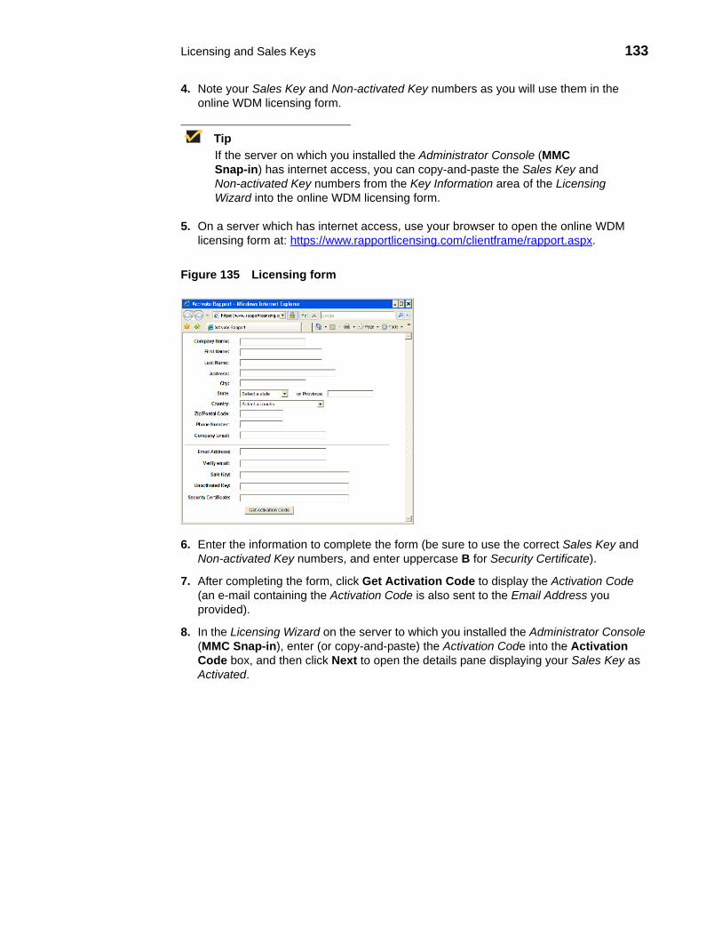
Licensing and Sales Keys 133
4. Note your Sales Key and Non-activated Key numbers as you will use them in the online WDM licensing form.
TipIf the server on which you installed the Administrator Console (MMC Snap-in) has internet access, you can copy-and-paste the Sales Key and Non-activated Key numbers from the Key Information area of the Licensing Wizard into the online WDM licensing form.
5. On a server which has internet access, use your browser to open the online WDM licensing form at: https://www.rapportlicensing.com/clientframe/rapport.aspx.
Figure 135 Licensing form
6. Enter the information to complete the form (be sure to use the correct Sales Key and Non-activated Key numbers, and enter uppercase B for Security Certificate).
7. After completing the form, click Get Activation Code to display the Activation Code (an e-mail containing the Activation Code is also sent to the Email Address you provided).
8. In the Licensing Wizard on the server to which you installed the Administrator Console (MMC Snap-in), enter (or copy-and-paste) the Activation Code into the Activation Code box, and then click Next to open the details pane displaying your Sales Key as Activated.

134 Appendix A
This page intentionally blank.

B Working with Groups and Views
This appendix includes advanced information on working with Groups and Views within WDM.
It includes:• "Understanding Groups Types and Views"• "Understanding the Show Empty Custom Group Folders Option"• "Assigning Devices to Groups"• "Moving Devices Across Custom Groups"• "Creating Views: A Working Example"
Understanding Groups Types and Views
TipFor information on managing Group Types, see "Managing Group Types."For information on managing Views, see "Managing Views."
Groups can be defined as a Group Type (predefined or custom), a Group Instance (within a Group Type), or any combination of these items. WDM allows you to use predefined Group Types (OS, Platform, Image/Firmware Image Number, Subnet, Location, TimeZone, VendorID, Custom1, Custom2, and Custom3) or create any number of custom Group Types and Group Instances to facilitate the organization of your devices into functional hierarchies. You can then use these groups to create custom Views of your devices.
Views offer a way to visually organize your devices functionally so that you can better manage them. Because WDM provides predefined Group Types and allows you to create custom Group Types and Group Instances, you can easily organize your devices in ways that best suit your organizational needs. By combining predefined Group Types, custom Group Types, and Group Instances you can achieve high levels of granularity in your Views (for information on creating Views, refer to "Managing Views").
In a simple View, you would have a single Group Type and any number of Group Instances to accommodate your devices. For example, assume that your company devices are spread among two buildings. You might want a View that organizes your devices by the building where the devices reside physically. In this example View case:• Every View is identified by a View name. In our example, the view name could be By
Building.• A single-level View uses one Group Type to organize the devices. In our example, the
Group Type is Building.• The Group Instances within the Group Type define specific instances of that Group
Type. In our example, Wyse I Building and Wyse II Building could be the two Group Instances of the general Group Type Building.
Multi-level Views use more than a single hierarchical level. Each additional level is nested within the larger level. Just as you can create your own custom Group Type for a

136 Appendix B
single-level View, you can continue creating custom Group Types for nested hierarchical levels. For example, assume that, in addition to organizing your devices by building, your company also wants to distinguish the devices in each building by the department in which each device operates. Such a View would assume a slightly more granular hierarchy than our simple View example. In this multi-level View case:• The View name should match the hierarchy of your view for easy identification. In our
example, the View could be named By Building => Departments. • Each Group Type corresponds to a view level in the View. In our example, Building is
the Group Type for the View Level-1, and Departments is the Group Type for View Level-2.
• The View Level-2 Groups are Group Instances of the Group Type for that level. In our example, groups such as Engineering, Sales, and Marketing are all Group Instances of the general Group Type Departments.
Understanding the Show Empty Custom Group Folders OptionWDM Views consist of hierarchies of folder groups, whether the folders are for a Group Type (predefined and/or custom), a Group Instance (within a Group Type), or any combination of these items. Show Empty Custom Group Folders is a Device Manager preference option that lets you select whether or not to include empty custom group folders in your Views (see "Device Manager Preferences").
When you create Views, it is generally recommended that you enable Show Empty Custom Group Folders. Every new folder for a custom group that you create starts out empty. If Show Empty Custom Group Folders is disabled, you will not be able to see newly created folders (or existing folders that have no devices in them) in your Views. For this reason, if the option is disabled while you are creating custom groups, WDM prompts you whether or not to enable Show Empty Custom Group Folders so you can see the folders that you are creating. After you have assigned devices among your custom groups, there may be some group folders to which you did not assign any devices. You can choose to disable the Show Empty Custom Group Folders option to remove the empty folders from the View so that the hierarchy reveals only folders with assigned devices.
Use the following guidelines when enabling or disabling the Show Empty Custom Group Folders option:• Using Predefined Group Types - The Show Empty Custom Group Folders option has
no effect on the WDM predefined Group Types. Empty predefined group folders never display in the Administrator Console, regardless of whether or not the Show Empty Custom Group Folders option is enabled. This prevents you from seeing folders for predefined Group Types that do not match the characteristics of any devices in your network. For example, if the Operating Systems of all of your devices is either CE or Thin OS, you would not want to show the empty folders for all of the other possible operating systems (Linux, Solaris, CE.Net, Windows 2000, and so on) when there are no such devices in your network. Note that you cannot move devices across the WDM predefined Group Types (for example, you cannot move a device from a CE OS group to an XPe OS group).
• Using Custom Group Types and Custom Instances - The Show Empty Custom Group Folders option should be enabled if you want to move devices from one custom group within the View to another custom group, particularly when some of your folders are still empty.
• Using Views with Folders of Predefined Group Types Only - As mentioned earlier, the Show Empty Custom Group Folders option has no effect on folders for predefined Group Types. Folders for predefined Group types will not show on a View unless there are devices that meet the characteristics of the predefined Group Types. For example,

Working with Groups and Views 137
if all of the devices in your network are either CE or Thin OS and you have a single-level View with the predefined Group Type of OS, the View would contain only groups for CE and Thin OS, but not groups for any of the other possible operating systems (Linux, Solaris, CE.Net, Windows 2000, and so on). In a View that contains predefined Group Types, WDM prevents you from moving devices across predefined Group Types. It would be illogical to move a device that has the CE OS to a folder of devices that have the Linux OS.
• Using Views with Folders of Custom Groups Types and Group Instances Only - If you have a View that uses only custom Group Types and Group Instances, and the Show Empty Custom Group Folders option is enabled, your View will show all of the group folders, regardless of whether or not the devices have been assigned to every folder. For example, in a single-level View there is only one custom Group Type, in this case Building. The Group Instances for this custom Group Type include the Wyse I Building and Wyse II Building. Because the Show Empty Custom Group Folders option is enabled, the View shows the folder for the Wyse I Building even though there are no devices in it (in a View such as this, you can move devices from the Wyse II Building to the Wyse I Building by dragging and dropping (see "Moving Devices Across Custom Groups"). However, if the Show Empty Custom Group Folders option is disabled, the View would show only the Wyse II Building (containing devices).
• Using Views with Folders of Predefined Group Types and Custom Group Types - When you have a View with both predefined Group Types and custom Group Types, the standard rules for each Group Type still apply. However, because a folder for a predefined Group Type can be a parent to children folders of custom Group Types, some special circumstances can arise. For example, even with Show Empty Custom Group Folders enabled, folders for custom Group Types that are children of a predefined Group Type will not be shown as long as all of the custom Group Type folders are empty. However, if a one of these children folders has a device assigned, all of the other sibling folders under the same parent folder will be shown.
Assigning Devices to GroupsWDM uses the following three methods to assign devices to groups (in the first two methods, WDM performs the device assignment without your direct intervention):• By System values of each device - When discovering a device, WDM examines the
system values of the device (Platform, Vendor ID, OS, and so on). It then automatically groups the devices into the corresponding predefined Group Types that are built-into WDM (OS, Platform, Image/Firmware Image Number, Subnet, Location, and Contact).
• By Custom Group Type and Group Instance within a Group Type associated with a subnet (Wyse Enterprise Edition Only) - When you define a subnet, WDM allows you to specify whether the devices in the subnet should be automatically assigned to a custom Group Type and Group Instance within that Group Type. For example, a custom Group Type named Department can serve to denote the various departments within an organization (Marketing, Sales, Engineering, and so on). In this example, each individual department is a Group Instance within the larger Group Type. To assign devices by subnet, you must create the Groups you want (Group Types and Group Instances) prior to assigning the subnet (see "Managing Views").
• By Manual assignment - After you have created a View and assigned devices to specific Group Types and Group Instances within those Group Types, you can manually drag-and-drop (assign) a device from one custom group within the View to another custom group. For example, if a View groups devices by department within buildings, you can easily drag-and-drop a device from the Engineering department in one building to the Marketing department in the same building or in another building (see "Moving Devices Across Custom Groups").
138 Appendix B
Moving Devices Across Custom GroupsAfter creating a View and then assigning the devices to specific custom Group Types and/or Group Instances, you can manually move devices from one custom group within the View to another custom group (for example, in cases where certain devices must be relocated to a new department or assigned to a different function).
WDM allows certain device moves and prevents others. For example, it does not allow you to move a device from a group of Linux devices to a group of CE devices. Be aware of the following rules of device movement:• You can move devices only across custom groups.• You cannot move devices between the WDM predefined Group Types. For example,
you cannot move a device from a CE OS group to an XPe OS group.• You can move a device from its source to a destination at a higher level in a different
branch. However, the device will move down the target branch to the group that matches the device characteristics from the originating group. If there is not a matching group for its device characteristics, the device spawns another set of groups to match the device characteristics from the originating group.
TipEnsure that the Device Manager preference Show Empty Custom Group Folders is enabled, so your View can display newly created/empty folders (see "Understanding the Show Empty Custom Group Folders Option").
To move devices across custom groups within a View:
1. Switch to the View in which you wish to move devices across groups.
2. Click the folder for the group that has the device or devices that you want to move to open the details pane displaying the devices in that group folder.
3. Select and drag the desired devices from the details pane to the desired target folder.

Working with Groups and Views 139
Creating Views: A Working ExampleThe process of creating Views can be divided into three stages. When creating your Views, use the guidelines discussed in the following sections.
Stage I: Determine Logical Groups and a Hierarchy for your View
1. Analyze your organizational structure along functional lines and determine how you can logically group your devices to better manage them. Then conceive the necessary categories (Group Types) that you can use to organize your devices. WDM allows you to use these Group Types to build hierarchies of device groups (Views) with any level of granularity you want. When your devices are grouped into hierarchies of Views, you can then easily manage and control them.
2. Determine ways of organizing the Group Types you conceived into functional hierarchies of devices (Views) for your organization. Just as WDM allows you to have unlimited Group Types, it also allows you to have any number of Views. You can create as many Views as is necessary to organize your devices. For example, if your Group Types include Building and Department, you could have one View that groups devices by building within each department. Conversely you could use the same Group Types and create a View that groups devices by department within each building.
3. Use the Configuration Manager of the Administrator Console to create the necessary Group Types to accommodate the organizational hierarchy you developed in the previous steps. To create a Group Type, use the Group Type node under Configuration Manager (see "Managing Group Types").
Stage II: Create a View and Select Its View Levels
4. A View name can be any text you want. However, it makes sense to assign names that correspond to the levels in your View so that you can easily identify your Views. By using arrows (=>) between each level, you can clearly establish the hierarchy of your View with the View name. After deciding on your naming conventions, you can create a View Name by using the Views node under Configuration Manager (see "Managing Views").
5. Every View requires you to select at least one view level. The number of view levels dictates the granularity of your device hierarchy. View levels equate to Group Types that you might have created earlier, in Stage I. Because our example includes Group Types for Building and Departments and our example View uses a two-level hierarchy of Building => Departments, you would select the Group Type Building as the first view level and Departments as the second view level. This hierarchical arrangement would allow you to group your devices by building and then within each building (by the department to which the devices belong).
Stage III: Create Group Instances and Prepare to Assign Devices to Groups
6. After creating a Group Type (in Stage I) and assigning it to a level view (in Stage II), you can create Group Instances for each Group Type. In our example, we created the Wyse I Building and Wyse II Building as Group Instances for the Group Type Building. Similarly, we created the groups Engineering, Sales, and Marketing as groups of the Group Type Departments. To create a Group Instance, use the Device Manager node at each view level.
Once you have created a View, you are ready to assign devices to groups. For example, you can drag-and-drop devices from the Unassigned folder into the appropriate folder for your View (the Unassigned folder serves as a container to hold devices until they are assigned to a Group Type or Group Instance). For information on assigning devices to groups, refer to "Assigning Devices to Groups."

140 Appendix B
This page intentionally blank.

C Upgrading WDM Agents
This appendix contains advanced information about upgrading WDM Agents. It also provides information on WDM Agent error codes.
The WDM Agent is a small Web agent that runs within the operating system of the device being managed. It has a very small footprint and is optimized for the thin client environment. The WDM Agent works with the WDM Services on the WDM Server to perform the actions that are needed by you, the administrator. The WDM Agent interprets the commands sent by the WDM Server and makes the necessary changes to the device being managed. In addition, the WDM Agent also provides status updates about the device to the WDM Server.
It includes:• "Using the Auto-Agent Upgrade Feature"• "Upgrading Older WDM Agents Selectively"• "Understanding WDM Agent Error Codes"
CautionUpgrading WDM Agents is supported on SUSE Linux Enterprise Desktop 11 and 11 SP1; it is not supported on SUSE Linux Enterprise Desktop 10.
Using the Auto-Agent Upgrade Feature The Auto-Agent Upgrade feature enables existing versions of the WDM Agent on a device to be upgraded automatically. With this preference enabled, a device is automatically upgraded to the most current version of the WDM Agent when the device is discovered (or checks-in).
CautionIn cases where you have FTP or HTTP limitations, or have a large number of devices with older WDM Agents on your network, this operation could take a significant amount of time. Therefore, it is recommended that you begin upgrading older WDM Agents selectively. After upgrading a number of the devices selectively, you can turn on the Auto-Agent Upgrade feature to complete the upgrading process, and to continue upgrading any new devices that are added to the network as WDM discovers them.
To enable automatic upgrading of WDM Agents:
1. In the tree pane of the Administrator Console, expand Configuration Manager and click Preferences.
2. Double-click Device Manager Preferences to open the Preferences dialog box.

142 Appendix C
Figure 136 Preferences—Device Manager
3. Select the Automatically Upgrade Older Agents check box, and set the Auto-Agent Upgrade Preferences you want (selecting Now starts the upgrading process immediately; selecting the clock option allows you to set the desired time to start the upgrading process—a recommended time is during low network activity).
TipBy default, the time zone specified is the Database Update Server time zone (to specify a different the time zone, refer to "Scheduling Preferences").
Be aware of the following:• The new packages installed with WDM are designed to upgrade existing WDM
Agent devices. These packages will fail if applied to v3.02 legacy managed devices. Separate Legacy Agent upgrade packages are available.
• WDM Agent upgrades use the first 3 digits of the version number to determine if a newer WDM Agent is available. The last digit is specific to WDM for internal control and is not used by Auto-Agent Upgrade.
• If any Default Device Configuration (DDC) exists with Enforce Sequence enabled, Auto-Agent Upgrade will trigger the DDC to re-image devices, which will trigger Auto-Agent Upgrade in an infinite regression. Rebuild existing DDCs with an image containing the newest WDM Agent.
4. After you have finished your settings, click OK.
TipFor information on editing or deleting a scheduled update, see "Managing the Schedules for Device Updates."

Upgrading WDM Agents 143
Upgrading Older WDM Agents SelectivelyBefore upgrading selectively, you should have configured WDM with subnet and/or IP range information (see "Managing Networks"), understand the WDM architecture, have discovered the devices you wish to upgrade (see "Managing Devices"), ensure that the Auto-Agent Upgrade feature is turned off in the Device Manager Preferences dialog box (see "Using the Auto-Agent Upgrade Feature").
Use the following guidelines to selectively upgrade older WDM Agents to the new HTTP-based WDM Agent:
1. Switch to the View you want in the Device Manager to identify the device or devices whose WDM Agents you want to upgrade to the new WDM Agent.
TipYou can distribute the WDM Agent package to multiple devices simultaneously by isolating the devices into one group. To isolate a group of devices, you can discover devices using a specific subnet or an IP range (see "Adding Devices Using Dynamic Discovery"). You can also create a View of devices by subnet, OS, or any other functional group (see "Managing Views").
2. Expand Package Manager, and select the Agent Updates folder to view the details pane displaying all the packages contained in the Agent Updates folder.
TipThe Agent Updates folder and other standard packages are included with every new installation of WDM to allow you to upgrade older WDM Agents.
3. Drag the WDM Agent package and drop it onto the Device Manager node in the tree pane of the Administrator Console (or onto a device group in the Device Manager) to open the Software Distribution Wizard.
4. Select the devices with the WDM Agents you want to upgrade and click Next.
TipSelected devices must match the OS of the WDM Agent software update package. Scroll to the right to determine the device OS (under the OS column) and use SHIFT or CTRL to select multiple devices. If you dropped the software package onto a device group, only the devices in that group are displayed.
Figure 137 Scheduling an Upgrade

144 Appendix C
5. Select and configure the distribution option you want for the WDM Agent upgrade and click Next.
6. After the wizard informs you that it is ready to create the update, click Next.
7. When the wizard finishes creating the update, click Finish.
TipFor information on editing or deleting a scheduled update, see "Managing the Schedules for Device Updates."
Understanding WDM Agent Error CodesThis section contains information on the following errors:• File Transfer Protocol Error Codes - The File Transfer Protocol (FTP) is a protocol
that is able to transfer files between machines with different operating systems. The FTP utility issues an error, or reply, code to every user command. FTP errors are discussed in "File Transfer Protocol (FTP) Error Codes."
• Windows Sockets Error Codes - When using any TCP/IP application, it is possible for errors to occur in both configuration and networking. Many applications do not report these errors, but simply tell you that you have a network error. A list of possible errors (as reported by Microsoft) is shown in "Windows Sockets Error Codes."
File Transfer Protocol (FTP) Error CodesThe following are excerpts from RFC 959 for FTP.
An FTP reply consists of a three-digit number (transmitted as three alphanumeric characters) followed by some text. The number is intended for use by automata to determine what state to enter next; the text is intended for the human user.
The three digits of the reply each have a special significance. This is intended to allow a range of very simple to very sophisticated responses by the user-process. The first digit denotes whether the response is good, bad or incomplete. An unsophisticated user-process will be able to determine its next action (proceed as planned, redo, retrench, and so on) by simply examining this first digit. A user-process that wants to know approximately what kind of error occurred (for example, file system error, command syntax error) may examine the second digit, reserving the third digit for the finest gradation of information.
First Digit
There are five values for the first digit of the reply code:• 1yz Positive Preliminary reply - The requested action is being initiated; expect
another reply before proceeding with a new command (the user-process sending another command before the completion reply would be in violation of protocol; but server-FTP processes should queue any commands that arrive while a preceding command is in progress). This type of reply can be used to indicate that the command was accepted and the user-process can now pay attention to the data connections, for implementations where simultaneous monitoring is difficult. The server-FTP process can send at most, one 1yz reply per command.
• 2yz Positive Completion reply - The requested action has been successfully completed. A new request can be initiated.
• 3yz Positive Intermediate reply - The command has been accepted, but the requested action is being held in abeyance, pending receipt of further information. The user should send another command specifying this information. This reply is used in command sequence groups.

Upgrading WDM Agents 145
• 4yz Transient Negative Completion reply - The command was not accepted and the requested action did not take place, but the error condition is temporary and the action may be requested again. The user should return to the beginning of the command sequence, if any. It is difficult to assign a meaning to transient, particularly when two distinct sites (Server- and User-processes) have to agree on the interpretation.
Each reply in the 4yz category might have a slightly different time value, but the intent is that the user-process is encouraged to try again. A rule of thumb in determining if a reply fits into the 4yz or the 5yz (Permanent Negative) category is that replies are 4yz if the commands can be repeated without any change in command form or in properties of the User or Server (for example, the command is spelled the same with the same arguments used; the user does not change his file access or user name; the server does not put up a new implementation).
• 5yz Permanent Negative Completion reply - The command was not accepted and the requested action did not take place. The User-process is discouraged from repeating the exact request (in the same sequence). Even some permanent error conditions can be corrected, so the human user may want to direct his User-process to re-initiate the command sequence by direct action at some point in the future (for example, after the spelling has been changed, or the user has altered his directory status).
Second digit (Function Groupings)
The following function groupings are encoded in the second digit: • x0z Syntax - These replies refer to syntax errors, syntactically correct commands that
do not fit any functional category, non-implemented or superfluous commands. • x1z Information - These are replies to requests for information, such as status or help.• x2z Connections - Replies referring to the control and data connections. • x3z Authentication and accounting - Replies for the login process and accounting
procedures. • x4z - Unspecified as yet.• x5z File system - These replies indicate the status of the Server file system through
the requested transfer or other file system action.
Third Digit
The third digit gives a finer gradation of meaning in each of the function categories specified by the second digit, as shown in the following list:
TipThe text associated with each reply is recommended, rather than mandatory, and may even change according to the command with which it is associated. The reply codes, on the other hand, must strictly follow the specifications in the last section; that is, Server implementations should not invent new codes for situations that are only slightly different from the ones described here, but rather should adapt codes already defined.
• 100· 110 Restart marker reply.· 120 Service ready in minutes.· 125 Data connection already open; transfer starting.· 150 File status okay; about to open data connection.

146 Appendix C
• 200· 200 Command okay.· 202 Command not implemented, superfluous at this site.· 211 System status, or system help reply.· 212 Directory status.· 213 File status.· 214 Help message.· 215 NAME system type.· 220 Service ready for new user.· 221 Service closing control connection. Logged out if appropriate.· 225 Data connection open; no transfer in progress.· 226 Closing data connection. Requested file action successful (for example, file
transfer or file abort).· 227 Entering Passive Mode (h1, h2, h3, h4, p1, p2).· 230 User logged in, proceed.· 250 Requested file action okay, completed.· 257 PATHNAME created.
• 300· 331 User name okay, need password.· 332 Need account for login.· 350 Requested file action pending further information.
• 400· 421 Service not available, closing control connection. This may be a reply to any
command if the service knows it must shut down.· 425 Can't open data connection.· 426 Connection closed; transfer aborted.· 450 Requested file action not taken. File unavailable (for example, file busy).· 451 Requested action aborted: local error in processing.· 452 Requested action not taken. Insufficient storage space in system.
• 500· 500 Syntax error, command unrecognized. This may include errors such as
command line too long.· 501 Syntax error in parameters or arguments· 502 Command not implemented.· 503 Bad sequence of commands.· 504 Command not implemented for that parameter.· 530 Not logged in.· 532 Need account for storing files.· 550 Requested action not taken. File unavailable (for example, file not found, or no
access).· 551 Requested action aborted: page type unknown.· 552 Requested file action aborted. Exceeded storage allocation (for current
directory or data set).· 553 Requested action not taken. File name not allowed.

Upgrading WDM Agents 147
Windows Sockets Error CodesWINSOCK Errors are generated when a script is running on a WDM Agent. In such a case, the WDM Agent either had trouble obtaining or sending a file as part of the script. The following is a list of possible errors (as reported by Microsoft):
TipErrors are listed in alphabetical order by error macro. Some error codes defined in Winsock2.h are not returned from any function—these are not included in this list:
• WSAEINTR 10004 - Interrupted function call. A blocking operation was interrupted by a call.
• WSAEACCES 10013 - Permission denied. An attempt was made to access a socket in a forbidden way.
• WSAEFAULT 10014 - Bad address. The system detected an invalid pointer address.• WSAEINVAL 10022 - Invalid argument. Some invalid argument was supplied.• WSAEMFILE 10024 - Too many open files. Too many open sockets. • WSAEWOULDBLOCK 10035 - Resource temporarily unavailable. Socket operation
not available at this time.• WSAEINPROGRESS 10036 - Operation now in progress. A blocking operation is
currently executing.• WSAEALREADY 10037 - Operation already in progress. An operation was attempted
on a non-blocking socket with an operation already in progress.• WSAENOTSOCK 10038 - Socket operation on non-socket. An operation was
attempted on something that is not a socket. • WSAEDESTADDRREQ 10039 - Destination address required. A required address
was omitted from an operation.• WSAEMSGSIZE 10040 - Message too long. A message sent on a datagram socket
was larger than the internal message buffer. • WSAEPROTOTYPE 10041 - Protocol wrong type for socket. A protocol was specified
in the socket function call that is not supported. • WSAENOPROTOOPT 10042 - Bad protocol option. An unknown, invalid or
unsupported call was made. • WSAEPROTONOSUPPORT 10043 - Protocol not supported. The requested protocol
has not been configured into the system. • WSAESOCKTNOSUPPORT 10044 - Socket type not supported. The support for the
specified socket type does not exist. • WSAEOPNOTSUPP 10045 - Operation not supported. The attempted operation is not
supported.• WSAEPFNOSUPPORT 10046 - Protocol family not supported. The protocol family has
not been configured into the system or no implementation for it exists. • WSAEAFNOSUPPORT 10047 - Address family not supported. An address
incompatible with the requested protocol was used.• WSAEADDRINUSE 10048 - Address already in use. An application attempts to bind a
socket to an IP address/port that has already been used for an existing socket.• WSAEADDRNOTAVAIL 10049 - Cannot assign requested address. The requested
address is not valid.• WSAENETDOWN 10050 - Network is down. A socket operation encountered a dead
network.

148 Appendix C
• WSAENETUNREACH 10051 - Network is unreachable. A socket operation was attempted to an unreachable network.
• WSAENETRESET 10052 - Network dropped connection. The connection has been broken due to keep-alive activity detecting a failure while the operation was in progress.
• WSAECONNABORTED 10053 - Software caused connection abort. A connection was aborted by the software in your machine, possibly due to a TCP/IP configuration error, data transmission time-out or protocol error.
• WSAECONNRESET 10054 - Connection reset by peer. An existing connection was forcibly closed by the remote host.
• WSAENOBUFS 10055 - No buffer space available. An operation on a socket could not be performed because the system lacked sufficient buffer space or because a queue was full.
• WSAEISCONN 10056 - Socket is already connected. A connect request was made on an already-connected socket.
• WSAENOTCONN 10057 - Socket is not connected. A request to send or receive data was disallowed because the socket is not connected.
• WSAESHUTDOWN 10058 - Cannot send after socket shutdown. A request to send or receive data was disallowed because the socket had already been shut down.
• WSAETIMEDOUT 10060 - Connection timed out. A connection did not properly respond after a period of time.
• WSAECONNREFUSED 10061 - Connection refused. No connection could be made because the target machine actively refused it.
• WSAEHOSTDOWN 10064 - Host is down. A socket operation failed because the destination host is down.
• WSAEHOSTUNREACH 10065 - No route to host. A socket operation was attempted to an unreachable host.
• WSAEPROCLIM 10067 - Too many processes. A Windows Sockets implementation may have a limit on the number of applications that can use it simultaneously.
• WSASYSNOTREADY 10091 - Network subsystem is unavailable. This error is returned if the sockets implementation cannot function because the system is currently unavailable.
• WSAVERNOTSUPPORTED 10092 - Winsock.dll version out of range. The current Windows Sockets implementation does not support the Windows Sockets specification version requested.
• WSANOTINITIALISED 10093 - Startup failed. The application socket startup failed.• WSAEDISCON 10101 - Graceful shutdown in progress. Returned to indicate that the
remote party has initiated a graceful shutdown.• WSATYPE_NOT_FOUND 10109 - Class type not found. The specified class was not
found.• WSAHOST_NOT_FOUND 11001 - Host not found. No such host is known.• WSATRY_AGAIN 11002 - Non-authoritative host not found. A temporary error during
host name resolution and means that the local server did not receive a response from an authoritative server.
• WSANO_RECOVERY 11003 - This is a nonrecoverable error. A nonrecoverable error occurred during a database lookup.
• WSANO_DATA 11004 - Valid name, no data record of requested type. The requested name is valid and was found in the database, but does not have the correct associated data being resolved for it.
• ERROR_INTERNET_TIMEOUT 12002 - Internet time-out. The request has timed out.

D About WDM Security
This appendix contains advanced information about WDM security.
It includes:• "Importing Certificates on Devices"• "Using Secure Communication (HTTPS)"
Importing Certificates on Devices Before starting secure communication between the components of WDM, import the certificate to the devices. There are two ways to import certificates. One is to create and deploy a package containing the certificate. The other is to create a DDC containing the certificate, and allow the DDC to automatically deploy the certificate to all devices. The import procedure depends upon the device OS.
TipCertificate Authentication: After deploying the certificate package to the devices, you need to authenticate the certificate with the server. The criteria for authentication of the certificate between the server and clients are based on the Certificate Issuing Authority, certificate creation date and name of the certificate. Upon successful certificate authentication, the server and the clients begin secure communication with one another.
Windows XPe
To import the certificate on devices running Windows XPe, you need to register two packages (like any other package you register in WDM). One package is for adding the certificate and the other package is for removing the certificate from the devices.
The folder structure for adding the certificate package is “\WDM Packages\CertificateAdd” and the folder “\WDM Packages\CertificateAdd” contains another “CertificateAdd” folder and the file “CertificateAdd.rsp”. The folder “CertificateAdd\ CertificateAdd” will contain the actual certificate file, named “root_cert.pem”.

150 Appendix D
A sample rsp file for adding the certificate to devices running Windows XPe is shown below:
[Version]Number=CertificateAddDescription=Installs a root CA CertificateOS=XPCategory=Other Packages[Script];;--------------------------------------------------------------------------;Check Operating System and Confirm free space;--------------------------------------------------------------------------CO "XP"CF "C" "200";--------------------------------------------------------------------------;Query User and Lockout;--------------------------------------------------------------------------LU;--------------------------------------------------------------------------;Copy over certificate file;--------------------------------------------------------------------------SF "<regroot>\root_cert.pem" "c:\Program Files\WDM\root_cert.pem";--------------------------------------------------------------------------;Update Registry & End Lockout;--------------------------------------------------------------------------SV "HKEY_LOCAL_MACHINE\SOFTWARE\RAPPORT\HAGENT\CAValidation" "1" "REG_DWORD"SV "HKEY_LOCAL_MACHINE\SOFTWARE\RAPPORT\HAGENT\CAPath" "c:\Program Files\WDM\root_cert.pem"EL
The folder structure for removing the certificate package is “\WDM Packages\CertificateRemove” and the folder “\WDM Packages\CertificateRemove” contains another “CertificateRemove” folder and the file “CertificateRemove.rsp”.
A sample rsp file for removing the certificate from devices running Windows XPe is shown below:
[Version]Number=CertificateRemoveDescription=Removes a root CA CertificateOS=XPCategory=Other Packages[Script];;;--------------------------------------------------------------------------;Check Operating System and Confirm free space;--------------------------------------------------------------------------CO "XP"CF "C" "200";--------------------------------------------------------------------------;Query User and Lockout;--------------------------------------------------------------------------LU;--------------------------------------------------------------------------;Delete certificate file;--------------------------------------------------------------------------DF "c:\Program Files\WDM\root_cert.pem";--------------------------------------------------------------------------;Update Registry & End Lockout;--------------------------------------------------------------------------DR "HKEY_LOCAL_MACHINE\SOFTWARE\RAPPORT\HAGENT\CAValidation"DR "HKEY_LOCAL_MACHINE\SOFTWARE\RAPPORT\HAGENT\CAPath"EL
CautionIn the device registry, if the CA Validation flag is set to 1, then certification validation occurs. If this flag is not set to 1, there is no certification validation on the client side.

About WDM Security 151
Windows CE .NET
To import the certificate on devices running Windows CE .NET, you need to register a package (like any other package you register in WDM) that contains the certificate file. For example, the folder structure for the certificate package is “WDM Package\CE_CertInstall” and the folder “CE_CertInstall” contains one folder named “CE_CertInstall” and the file “CE_CertInstall.rsp”. The folder “CE_CertInstall\ CE_CertInstall” contains two files, a text file named “CRC.txt” and the actual certificate file, named “root_cert.cer”.
A sample .rsp file for installing the certificate on devices running Windows CE is shown below:
[Version]Number=CE_CertInstallDescription=Installs a Certificate to a CE .NET deviceOS=CENCategory=Other Packages
[Script];;--------------------------------------------------------------------------;Check Operating System and Confirm free space;--------------------------------------------------------------------------CO "CEN"
;--------------------------------------------------------------------------;Query User and Lockout;--------------------------------------------------------------------------LU;--------------------------------------------------------------------------;Update Registry & End Lockout;--------------------------------------------------------------------------SV "HKEY_LOCAL_MACHINE\SOFTWARE\WYSE\AutoLoadCert\AutoLoadCert" "1" "REG_DWORD"SV "HKEY_LOCAL_MACHINE\SOFTWARE\WYSE\AutoLoadCert\CertFiles\Root" "root_cert.cer"
SF "CECert" "<regroot>\root_cert.cer" "\flash1\root_cert.cer"
ELRB
A sample .rsp file to turn certificate validation on or off for Windows CE .NET devices is shown below:
[Version]Number=CE_CertValOffDescription=Turns Certificate Validation OFF for a CE .NET deviceOS=CENCategory=Other Packages
[Script];DATE: 26 Sept 2008;;--------------------------------------------------------------------------;Check Operating System and Confirm free space;--------------------------------------------------------------------------CO "CEN";--------------------------------------------------------------------------;Query User and Lockout;--------------------------------------------------------------------------LU;--------------------------------------------------------------------------;Update Registry & End Lockout;--------------------------------------------------------------------------SV "HKEY_LOCAL_MACHINE\SOFTWARE\RAPPORT\HAGENT\CAValidation" "0" "REG_DWORD"ELRB

152 Appendix D
Wyse Thin OS
To import the certificate on devices running Wyse Thin OS (WTOS), you need to register two packages (like any other package you register in WDM). One package is for adding the certificate and the other package is for removing the certificate from the devices. When you want to add or delete a certificate, you need to change the wnos.ini file and register two separate packages.
The folder structure for the certificate package is WDM Package\CADeployment and the folder named CADeployment contains one folder named wnos. The folder named wnos contains a folder named cacerts and a file named wnos.ini. The folder named cacerts contains the actual certificate file.
A sample wnos.ini for adding the certificate is shown below:# Bypass the user log in to the local devicesignon=0
# Set the Privilege to highPrivilege=high
# Command to Import the certificate to WTOS devicesAddCertificate= CA certificate file nameA sample wnos.ini to delete a certificate is shown below:# Bypass the user log in to the local devicesignon=0
# Set the Privilege to highPrivilege=high
# Command to delete the certificate in WTOS devicesDelCertificate= CA certificate file nameA sample rsp file for adding the certificate to WTOS devices is shown below:[Version]
Number=CADeploymentDescription=CA Certificate DeploymentOS=BLCategory=ImagesImageSize=
[Script]

About WDM Security 153
Using Secure Communication (HTTPS)Beginning with WDM v4.7.0, WDM supports secure HTTPS communication between components of WDM.
TipSecure communication between client devices and the WDM server requires HAgent version 5.1.0.15 or later for XPe and HAgent version 4.7.11.x or later for CE.Net.
The secure communication can be initiated in two ways:• HTTPS Communication Initiated by HAgent• HTTPS Communication Initiated by the WDM Administrator Console
HTTPS Communication Initiated by HAgentThe HAgent can initiate communication with the HServer during client device startup. When the HAgent on a client boots up, it requests the following information from the DHCP server or proxy server:• Server IP address• HTTPS port number used for communication
If the HAgent can retrieve the HTTPS port number from the DHCP option tags, it uses the IP address and port number to communicate with the HServer via HTTPS.
If the HAgent cannot retrieve the HTTPS Port number from the DHCP option tags, it follows the sequence below:
1. The HAgent tries to communicate via HTTPS using ports 443 and 8443.
2. If the HAgent cannot communicate via HTTPS, it tries to connect via HTTP using ports 80 and 280.
3. If the HAgent successfully initiates communication with the HServer, it caches the communication mechanism, IP address, and port number used and uses that information for any subsequent requests.
4. If HTTPS communication fails during startup, the HAgent will not try the HTTPS protocol again.
CautionFor devices using WDM releases earlier than WDM 4.7, the HAgents can initiate communications with the HServer via HTTP, if that protocol is enabled on IIS. If you disable HTTP communications via the IIS settings to enhance security, the HAgents cannot communicate with the HServer.

154 Appendix D
HTTPS Communication Initiated by the WDM Administrator ConsoleYou can configure your network to allow the Administrator Console to determine the port number and protocol to use for communication with the HServer.
Determining the Port NumberTo allow the Administrator Console to determine the port number for communication:
1. Configure the IIS that hosts the HServer with the desired port number.
2. Stop the IIS and WWW service.
3. Start the HServerInit service.
When the Administrator Console starts, it queries the database to retrieve the port number and IP address to use for communication with the HServer.
Determining the ProtocolTo allow the Administrator Console to determine the protocol for communication:
1. Bind the IIS that hosts the HServer with a TCP, SSL, or TCP and SSL port.
TipFor an SSL port, you must install a certificate.
2. Stop the IIS and WWW service.
3. Start the HServerInit Service.
The port number and IP address are stored in the WDM Database.
If the request came via SSL, the entire WDM configuration is set to secure.
CautionFor devices using WDM releases earlier than WDM 4.7, the devices can communicate with the WDM server via HTTP, if that protocol is enabled on IIS. If you disable HTTP communications via the IIS settings to enhance security, the devices cannot communicate with the WDM server.
No configuration is required in the Administrator Console, but the Secure Communications check box will appear in the Port Settings Preferences dialog box for information purposes.

About WDM Security 155
Figure 138 Port Settings Preferences
If an SSL port is configured on IIS, the Secure Communications check box will be checked, otherwise it will be unchecked.
Before starting secure communication, make sure all the following settings are configured:• GUI Listening Port is 280.• Alternate GUI Listening Port Range is 49152 through 49161.• Standard Service Listening Port is 8008.• Web Server HTTP Port is 80.• Web Server HTTPS Port is 443.• Secure Communications will be checked (selected).• Use Host can be selected (enabled) to have the HAgent use the Server Host Name
you enter to connect to the server. Note that the Server Host name will have a default value of the Host machine and an Administrator can change this value to a different host name (useful in cases of request forwarding through an HTTP Proxy).
TipThe secure communications flag applies to both remote and master repositories.

156 Appendix D
This page intentionally blank.

E WDM ScriptBuilder Tool and Scripting LanguageThis appendix contains advanced information about using the WDM ScriptBuilder and using the WDM scripting language to create WDM Packages.
It includes:• "Using WDM Scripting Language"• "Using the WDM ScriptBuilder Tool"• "Understanding the WDM Package Structure"• "Optional Arguments and HKEY_CURRENT_USER"• "Understanding the Script File Structure"• "Version"• "Script"
Using WDM Scripting LanguageThe WDM scripting language was designed to allow you to create your own software packages (with or without the WDM ScriptBuilder Tool). A software package consist of a script (.rsp) file and any required application or image files. You can create a software package, and then register and distribute it to one or more devices using WDM.
Distributing software packages to one or more devices on the network saves time but requires caution and planning. It is very important that you test your software package on a separate test device to ensure validity and reliability.
CautionIt is imperative that all software packages be thoroughly tested before mass distribution occurs. This is the responsibility of the WDM administrator with package distribution permissions.

158 Appendix E
Using the WDM ScriptBuilder ToolThe WDM ScriptBuilder Tool is designed to help you manage (create, edit, and view) WDM scripting packages. For details on the script commands available for you to use with WDM ScriptBuilder, see "Script."
Creating a New WDM Script Package1. Click Start > All Programs > Wyse Device Manager > ScriptBuilder to open the
ScriptBuilder Tool.
Figure 139 WDM ScriptBuilder
2. Click New Package and then use the following guidelines:• Enter the Package Name and Package Name Description (so you can easily
recognize it later).• Select a Package Category.• Select an Operating System.• Select the script command you want to add to the from the Script Commands list. • Enter the Value of the command you want (some Parameters will automatically
enter a default Value). For details on the values available for you to use, see "Script."
• Click >> to add the script command to the script package pane.• You can continue to select the script commands in the Script Commands list you
want to add to the script package pane. • When adding script commands to the script package pane, you can select an item
in the script package pane and use the add, remove, move up, and move down command button arrows (which are automatically enabled and disabled according to possible or logical operations) as needed to build the script package you want.
• You can also edit existing script in the script package pane directly by double clicking the entry and making your modifications in the selected row, however, no command syntax or parameter validation is performed in this mode.
• Use Sample Script (opens a form with a typical sample script), Command Help (detailed help for commands selected in the Script Commands list), and General Help (general help with scripting) as needed for information.
3. After configuring the WDM scripting package you want, click Save.

WDM ScriptBuilder Tool and Scripting Language 159
Editing a New WDM Script PackageClick Start > WDM > WDM ScriptBuilder to open the ScriptBuilder dialog box, click Open Package, select the package you want to edit, and then use the guidelines in "Creating a New WDM Script Package."
TipModifications you make to an existing script package are shown in blue within the script package pane to indicate a change from the original package script.
Reviewing a New WDM Script PackageClick Start > WDM > WDM ScriptBuilder to open the ScriptBuilder dialog box, click Review Script, and then select the package you want to open a read only version of the script for review.
Understanding the WDM Package StructureA WDM Package structure consists of two components:• The Package script (.rsp) file (ImgXL24.rsp)• The Package folder that contains the required application or image files (ImgXL24)
In order for a Package to function properly, these two components must adhere to the following structural rules:• The Package script file must have an .rsp extension. You can create and edit an .rsp
file using Notepad.• The Package folder must have the same name as the Package script file. • The Number= parameter in the [Version] section of the Package script file should
match the value reported by the device to the Client Manager. This becomes extremely important when using the Default Device Configuration feature.
• All the files referenced by the Package script file must be within the Package folder or a sub-folder within.
• All command arguments should be enclosed in double-quotes and are separated by spaces ONLY.
• All registry paths are delimited with backslashes (‘\’) and are within quotes.• Do not use abbreviations for the root registry keys (e.g. use
HKEY_LOCAL_MACHINE, not HKLM).• All filenames are delimited with backslashes (‘\’) and are within quotes.• Neither path names nor registry branches should ever end with a backslash.• In general, a script is aborted if a command fails. If you do not want the script to abort if
a command fails, then appended the command with and asterisk (*). (Note not all commands support this).
• <REGROOT> (e.g. <regroot>\sourcefile.txt) points to the root directory of the registered package (e.g. c:\inetpub\ftproot\rapport\<packagename>).
Tip<regroot> is a pointer that tells the WDM Service to look in a specific location on the WDM server (not the device) for Package application files. <regroot> finds the WDM Master Repository and identifies the folder contained within that is holding the needed Package files.

160 Appendix E
Optional Arguments and HKEY_CURRENT_USERFour commands have optional arguments related to operations on the HKEY_CURRENT_USER registry branch.
The WDM service HKEY_CURRENT_USER registry branch is not related to any user HKEY_CURRENT_USER branch, so changes made directly to HKEY_CURRENT_USER typically do not have the desired effect. When called with their optional UserName arguments these four commands translate all references to HKEY_CURRENT_USER to HKEY_USERS\<username’s SID>.
TipThese commands will fail if the given user is not logged-on at the time of distribution.
Understanding the Script File StructureA WDM script (.rsp) file is one of two components that make up a WDM Package:• The Package script (.rsp) file (ImgXL24.rsp)• The Package folder that contains the required application or image files (ImgXL24)
The Package script (.rsp) file must conform to a specific structure and should contain two sections:• Version • Script
Version
The Version section contains information required for package registration and distribution purposes. The following describes each of the elements of the Version section:
[Version] - Required section header
Number= - Must be the same as the Package Script File name
Description= - A brief description of what the Package is to achieve
OS= -The Operating System the Package is intended for
USE_REMOTE= - YES/NO, specifies whether or not a Remote Repository (if it exists) should be used. Default is YES. (OPTIONAL)
DEPLOYEDSW= - YES/NO defines whether package should be added to the WDM deployed package table for device. Default is YES. (OPTIONAL)
Category= - The WDM Package Manager category in the Administrator Console where the package will reside. Note if the category does not exist it will be created.
Image Category Special Tags
[Version] - Required section header
ImageSize= - size of image in Megabytes
BootFloppy= - name of bootfloppy; default is RAPPORT
Use_PXE= - YES/NO default value is YES for all scripts with Category=IMAGES
IMAGE= - name of image file to be used; by default WDM uses the first file in file found in the package folder (excluding CRC.text)
Command= - the image operation to be performed

WDM ScriptBuilder Tool and Scripting Language 161
Script
The Script section contains the commands that are carried out when the script is distributed. Each command is executed in order as they appear within the [Script] section.
Recommended Scripting Template[Version]Number=Script name (matching the RSP_ file name and Package folder name)Description=Detailed description with version number and valid imagesOS=XXCategory=Other Packages[Script]Written by: Your Name and Company; ....................................................................................; >Check the Operating System
; >Check the Image Version; .....................................................................................CO "NT"CI “XXXX”; .....................................................................................; >Check Free Space; >Check Minimum Memory, if necessary; >Check User, if necessary; .....................................................................................CF “X” “XXX”CR “XXXX”CU “XXXXXXXX”; .....................................................................................; > Query User then lock Workstation; .....................................................................................QULU*; .....................................................................................; >Add Commands Here; .....................................................................................;SF “<regroot>\files\x.xxx” “c:\yyyy\zzzz”;EX “c:\yyyy\zzzz”;DF “c:\yyyy\zzzz”;MR “<regroot>\xxxx.reg”;SP "c:\windows\system.ini" "DISPLAY" "screen-size" "640"; .....................................................................................; >End Lockout; .....................................................................................EL*; .....................................................................................; >Reboot, if necessary; .....................................................................................RB--------------------------------------------------------------------------------

162 Appendix E
VersionThe Version section contains information required for package registration and distribution purposes.
BootFloppy=Specifies the boot floppy WDM uses during the imaging process:• Rapportitf.0 (WDM Imaging agent for WISard imaging)• pxelinux.0 (for Merlin imaging).
Category=Defines the category for the Package. If you type a different category name in Category=, and then register the Package using WDM, a folder is created under the Package Manager with that name.
TipA package can be moved from one category to another by changing Category= and re-registering the package.
Command=The image operation to be performed.
Example: Command=%ImageWrite%
Possible Values:• %ImageWrite% (This value writes to the DiskOnChip)• %ImageRead% (This value reads from the DiskOnChip)
DeployedSW=This defines whether the package should be added to the WDM deployed package table for the device.
DEPLOYEDSW=Yes or No - Default is Yes if not specified or specified incorrectly. This option is used primarily in conjunction with DDC. If a DDC has Enforce Sequence enabled any package sent to the device will trigger the DDC to re-image the device (thereby removing all packages). Using DeployedSW=No allows the user to send packages to devices without logging their distribution, thereby not triggering a DDC operation.
Description=Allows the script developer to add a short description about the Package. The description is a comment line and is not parsed by WDM when the script is executed.
Image=This defines the file name to be used when reading or writing an image for PXE operation.
Image=filename - The default is the first file found in <regroot> excluding CRC.txt.

WDM ScriptBuilder Tool and Scripting Language 163
ImageSize=Identifies for WDM the size of image being sent to a client.
Values: 8, 16, 24, 32, 48, 64, 72, 80, 96, 128, 144, 192, 256, 512, 1024
Number=Identifies for WDM the name of the Package. The name of the Package script (.rsp) file must match the Number= parameter. For example, if the Package script name is ImgXL24.rsp, you must have Number=ImgXL24 in the [Version] section of ImgXL24.rsp.
Example:[Version]Number=[Number reported by device in Device Manager under Image]Description=Image to Write to Device OS=NTCategory=ImagesUSE_PXE=YESUSE_REMOTE=NODEPLOYEDSW=YESIMAGE=[xyz24xl.img]IMAGESIZE=24
OS=Defines the Operating System the device is running.
Values:• XPe Windows XPe• CE Windows CE 2.12• CEN Windows CE .NET• CE Windows CE 3.0• WES Windows Embedded Standard• LX Tuxia Linux• BL WTOS• RLX Red Hat Linux • SLX SUSE Linux• LVE Viance OS
Use_PXE=WDM utilizes Intel's® Wired for Management standard Preboot eXecution Environment (PXE) to load images to devices. The default is Yes if Category=Images and No for all other Categories (Categories<>Images) if not specified or specified incorrectly.
If Boot from LAN is enabled in the BIOS, then Use_PXE=.
If you want the Package to be recognized by WDM as a non-imaging package, or you are working with systems that are not PXE enabled, then type No as the value.
Values: Yes and No
Use_Remote=This defines whether the package (script verbs and PXE) should use a Remote Repository assigned to its subnet or if it should always use the Master.
Use_Remote=Yes or No - Default is Yes, if not specified or specified incorrectly.

164 Appendix E
ScriptThe Script section contains the WDM commands that are carried out when the script is distributed. Each command is executed in order as they appear within the [Script] section.
Append FileVerb: AF
Description: Adds the specified text as a new line at the end of specified device filename.
Support: XPe, Linux
Arguments:• Path and filename• New text line
Usage:• XPe Usage
Continue if Script Command Fails: NoExamples:· AF "c:\temp\example.txt" "new line text" (This will add the line "new line text" to the
end of example.txt located at c:\temp\)• Linux Usage
Continue if Script Command Fails: NoExamples:· AF "/wfs/Append.txt" "new line text" (This will add the line "new line text" to the end
of Append.txt located at /wfs)
General Rules:• This command will append a new line of text to the end of a text file. If the file does not
already exist it will be created. This can be very useful in adding additional commands to batch and script files.
TipThe destination directory must exist for this command to work.
Confirm Disk Free SpaceVerb: CF
Description: Confirms the free space is greater than the specified amount on the specified device drive.
Support: XPe, CE 2.12, CE.Net, CE 3.0, Linux
Arguments:• Device drive letter (no colon required; for CE and Linux, it must be blank)• Kilobytes free
Usage:• XPe Usage
Continue if Script Command Fails: NoExamples:• CF "C" "2048" (Confirms there is at least 2MB of free space on the C:\ drive)

WDM ScriptBuilder Tool and Scripting Language 165
• CE UsageContinue if Script Command Fails: NoExamples:· CF "" "2048" (Confirms there is at least 2MB of free space on the storage device)
• Linux UsageContinue if Script Command Fails: NoExamples:· CF "" "512" (Confirms there is at least 2MB of free space on the storage device)
General Rules:• This command should be included on all scripts.• Do not include a colon with the device drive letter.
Confirm File VersionVerb: CV
Description: Confirms the device filename against the operand and value specified.
Support: XPe, CE.Net, CE 3.0
Arguments:• Device filename (CE Add-on name)• Test (<, =, >, <=, >=, or !=)• Value (decimal #)
Usage:• XPe Usage
Continue if Script Command Fails: NoExamples:· CV "c:\Program Files\Rapport\HAgent.exe" ">=" "4.0.0.73" (Verifies HAgent.exe is
version 4.0.0.73 or higher)· CV "c:\windows\system32\mfc42.dll" "!=" "6.0.9586.0" (Verifies mfc42.dll is not
version 6.0.9586.0)• CE Usage
Continue if Script Command Fails: NoExamples:· CV "ICA" ">=" "0019" (Verifies ICA addon is version 019 or higher)· CV "ICA" "=" "0023" (Verifies ICA addon is version 0023)· CV "ICA" "<" "0031" (Verifies ICA addon is less than version 0031)
TipCV command is NOT supported on CE.212
General Rules:• For a CE Add-on name, use the Add-on name as reported in the Administrator
Console.

166 Appendix E
Confirm ImageVerb: CI
Description: Confirms the device operating image. This command uses the first characters (same number of characters specified in parameter) of the image number in image.ver on the device.
Support: XPe, CE 2.12, CE.Net, CE 3.0, Linux
Arguments:• Image version substring
Usage:• XPe Usage
Continue if Script Command Fails: NoExamples:· CI "1.2" (Verifies device Image Number begins with 1.2. Thus 1.21, 1.256, 1.295.45
will all report success)· CI "2.00297.192" (Verifies device Image Number begins with 2.00297.192)
• CE UsageContinue if Script Command Fails: NoExamples:· CI "441" (Verifies device Image Number begins with 441. Thus 441.6, 441.22 and
441.39.7 will all report success)· CI "486.7.1" (Verifies device Image Number begins with 486.7.1)
• Linux UsageContinue if Script Command Fails: NoExamples:· CI "3.6.3.00.5" (Verifies the device Image Number)· CI "3.6.3." (Verifies the device Image Number)· CI "3." (Verifies the device Image Number)
General Rules: • This command should be included on all scripts.• The Image version substring behaves as if a wildcard were present at the end of the
image number. For example, if command was CI=“441”, image numbers 441.22 and 441.23 would pass. Images 440 and 442 would fail.
Confirm Minimum RAM Size Verb: CR
Description: Confirms the device has at least the specified amount of memory.
Support: XPe, CE 2.12, CE.Net, CE 3.0, Linux
Arguments:• The minimum amount of RAM in Kilobytes
Usage:• XPe Usage
Continue if Script Command Fails: NoExamples:· CR "16000" (Verifies that device has a minimum of 16MB of RAM)

WDM ScriptBuilder Tool and Scripting Language 167
• CE UsageContinue if Script Command Fails: NoExamples:· CR "16000" (Verifies that device has a minimum of 16MB of RAM)
• Linux UsageContinue if Script Command Fails: NoExamples:· CR "32000" (Verifies that device has a minimum of 32000MB of RAM)
General Rules:• This command should be included on all scripts where software is being deployed that
requires a certain amount of memory.
Confirm Operating SystemVerb: CO
Description: Confirms the device operating system. This command uses a character string representation for OS type (that is, CO “XPe”).
Support: XPe, CE 2.12, CE.Net, CE 3.0, Linux
Arguments:• Device operating system• Optional CE version arguments (valid only for CE)
Usage• XPe Usage
Continue if Script Command Fails: No· XP=Windows XPExample:· CO "XP" (Verifies that Operating System is XP)
• CE UsageContinue if Script Command Fails: NoCE=CE 2.12, orCEN=CE.Net, orTPC=CE 3.0Examples:· CO "CE" (Verifies OS is CE 2.12)· CO "CEN" (Verifies OS is CE.Net. Returns true if OS is CE.Net version 4.0 or 4.10)· CO "CEN" "4.10" (Verifies OS is CE.Net version 4.10; Returns true if OS is CE.Net
4.10; Returns false if OS is CE.Net version 4.0)• Linux Usage
Continue if Script Command Fails: NoLX=Tuxia LinuxExample:· CO "LX" (Verifies that Operating System is LX)
General Rules:• This command should be included on all scripts.

168 Appendix E
Confirm UserVerb: CU
Description: Confirms that the specified user is logged into the device.
Support: XPe
Arguments:• Username
Usage:• XPe Usage
Continue if Script Command Fails: NoExamples:· CU "Administrator" (Verifies 'Administrator' is currently logged on)
General Rules:• This command should be included on all scripts that have user-specific registry
commands.
Delete FileVerb: DF
Description: Deletes the specified device filename (analogous to DEL or rm).
Support: XPe, CE 2.12 (limited support), CE.Net (limited support), CE 3.0, Linux
Arguments:• Path and Filename
Usage:• XPe Usage
Continue if Script Command Fails: YesExamples:· DF “c:\winnt\filetodelete.txt” (Deletes specific file from device)
• CE UsageContinue if Script Command Fails: YesExamples:· DF“\Windows\filetodelete.txt” (Deletes specific file from device)Wyse devices support limited DF commands:· DF "Gkeyreset" (Resets device to factory defaults)· DF "CEAddon" "<addon name>" (Removes Add-on named in 3rd argument)
• Linux UsageContinue if Script Command Fails: YesExamples:· DF "/wfs/SendTest/filetodelete.txt" (Deletes specific file from device)
General Rules:• Device filename should include the path.

WDM ScriptBuilder Tool and Scripting Language 169
Delete Registry BranchVerb: DB
Description: Deletes the specified registry branch.
WarningUse this command carefully. Once executed, it cannot be undone.
Support: XPe
Arguments:• Device key string• User profile (not used with CE) [Optional]
Usage:• XPe Usage
Continue if Script Command Fails: YesExamples:· DB "HKEY_LOCAL_USER\Printers" "user" (Deletes specified registry branch from
user profile)
General Rules:• The name of the registry hive should not be abbreviated.• The WDM Agent runs in the system security context. Because of this,
HKEY_CURRENT_USER for WDM is the system user, not the currently logged in user. To overcome this, a special username argument must exist that tells the agent to apply the changes to the specified user rather than the system user. The specified user must be logged into the box for this command to succeed. Note that the user profile name is used to resolve the hive location. The profile name and username can be different.
Delete Registry ValueVerb: DR
Description: Deletes the specified device registry key. The option username is used to change user specific registry values. The REDEDIT file must use HKEY_CURRENT_USER. WDM will change this to HKEY_USERS_USERSID
WarningUse this command carefully. Once executed, it cannot be undone.
Support: XPe
Arguments:• Device key string• User profile [Optional]
Usage:• XPe Usage
Continue if Script Command Fails: YesExamples:· DR “HKEY_CURRENT_USER\CONTROL PANEL\COLORS\background” “user”
(Deletes specified registry key from 'user's' profile)

170 Appendix E
General Rules: • The name of the registry hive should not be abbreviated.• The WDM Agent runs in the system security context. Because of this,
HKEY_CURRENT_USER for WDM is the system user, not the currently logged in user. To overcome this, a special username argument must exist that tells the agent to apply the changes to the specified user rather than the system user. The specified user must be logged into the box for this command to succeed. Note that the user’s profile name is used to resolve the hive location. The profile name and username can be different.
• DR must be followed by the Reboot command (RB) for the changes to take effect.
Delete TreeVerb: DT
Description: Deletes the specified device directory and its contents (analogous to DELTREE or rm –R).
WarningUse this command carefully. Once executed, it cannot be undone.
Support: XPe, Linux
Arguments:• Device directory
Usage:• XPe Usage
Continue if Script Command Fails: YesExamples:· DT "C:\Test" (Deletes the 'Test' folder and all files within it)
• Linux UsageContinue if Script Command Fails: YesExamples:· DT "/wfs/Test" (Deletes the 'Test' folder and all files within it)
General Rules:• None
End LockoutVerb: EL
Description: Removes the splash screen displayed by the LU command on the client device.
Support: XPe, CE 2.12, CE.Net
Arguments:• None
Usage:• XPe Usage
Continue if Script Command Fails: YesExamples:· EL

WDM ScriptBuilder Tool and Scripting Language 171
• CE UsageContinue if Script Command Fails: YesExamples:· EL
General Rules:• This command should always be used in conjunction with a LU. It is recommended that
all non-image scripts use this command.
Execute on DeviceVerb: EX
Description: Executes the specified client filename (assumes the specified file is executable).
Support: XPe
Arguments:• Path and filename• Synchronous execute [Optional]
Usage:• XPe Usage
Continue if Script Command Fails: YesExamples:· EX "c:\test.exe" (Launches c:\test.exe on the device and continues to next
command in script)· EX "c:\test.exe" "+" (Launches c:\test.exe on the device and pauses until the
executable is finished before continuing with next command in script)· EX "c:\test.exe" "+30" (Launches c:\test.exe on the device and pauses until the
executable is finished or 30 seconds have elapsed, whichever occurs first, before continuing with the next command in script)
General Rules: • The command may be issued exactly as it would be from a command prompt on the
device.• In Windows, the path may be omitted if the executable is a registered Windows
application • The optional synchronous argument stops script processing until the executable is
finished. This option can be expressed as "+" with no timeout or "+n" where n indicates the maximum time in seconds to wait before continuing script processing.
TipBecause of differences between process and system speeds, it is HIGHLY recommended that this option be used.

172 Appendix E
Get FileVerb: GF
Description: Copies the specified device filename to the specified master repository filename (analogous to COPY or cp).
Support: XPe, CE 2.12, CE.Net, CE 3.0, Linux
Arguments:• Device filename (source)• Master repository filename (destination)
Usage:• XPe Usage
Continue if Script Command Fails: NoExamples:· GF "c:\temp\temp.txt" "<regroot>\temp.txt" (Pulls temp.txt from the device to the
Master repository)• CE Usage
Continue if Script Command Fails: NoExamples:· GF "\Windows\temp.txt" "<regroot>\temp.txt" (Pulls temp.txt from the device to the
Master repository)Wyse devices have limited GF support:· GF "CEConfig" "<regroot>\Settings.reg" (Exports device registry to Settings.reg on
the Master repository)• Linux Usage
Continue if Script Command Fails: NoExamples:· GF "/wfs/SendTest/zero1.txt" "<regroot>\zero.txt" (Pulls zero1.txt from the device to
zero.txt in the Master repository)
General Rules: • Get operations always pull to the Master repository.• Source and target filenames should include the complete path.• The destination path should be defined with <regroot>.
Get Registry Verb: GR
Description: Exports the specified device registry branch. The resulting local filename will be in REGEDIT4 format.
Support: XPe
Arguments:• Device registry branch• Master repository filename (destination)
Usage:• XPe Usage
Continue if Script Command Fails: No

WDM ScriptBuilder Tool and Scripting Language 173
Examples:· GR “HKEY_LOCAL_MACHINE\SOFTWARE\Rappport” "<regroot>\Rapport.reg"
(Exports WDM registry settings to Rapport.reg in the script folder)
General Rules: • Get operations always pull to the Master repository.• The name of the registry hive should not be abbreviated.• The resulting local filename will be in REGEDIT format.• The destination should include the complete path, defined with <regroot>.
Get Registry ValueVerb: GV
Description: Gets a single registry value to a file. The following types are supported:• REG_SZ• REG_MULTI_SZ• REG_EXPAND_SZ• REG_DWORD• REG_BINARY
The output file types are:• Windows NT 4.0: REGEDIT4 format, PC/ANSI• Windows 2K/XP: Regedit v5.00, PC/UNICODE
TipCertain registry keys may be locked by the OS and interfere with GV operations. Verify with the device manufacture that the registry value is not locked. Registry value changes will not be persistent unless the device is rebooted using one of the following:Via the RB (reboot) commandRight-click rebootManual operation
Support: XPe, CE 2.12, CE.Net, CE 3.0
Arguments:• The full path of the registry key, including the registry entry name• Master repository filename (destination)
Usage:• XPe Usage
Continue if Script Command Fails: NoExamples:· GV "HKEY_LOCAL_MACHINE\SOFTWARE\Rapport\hAgent\TestValue1"
"<regroot>\TestValue1.reg" (Pulls TestValue1 to TestValue1.reg in the script folder)• CE Usage
Continue if Script Command Fails: NoExamples:· GV "HKEY_LOCAL_MACHINE\SOFTWARE\Rapport\hAgent\TestValue1"
"<regroot>\TestValue1.reg" (Pulls TestValue1 to TestValue1.reg in the script folder)

174 Appendix E
General Rules: • Get operations always pull to the Master repository.• The name of the registry hive should not be abbreviated.• The resulting local filename will be in REGEDIT format.• The destination should include the complete path, defined with <regroot>.
Local PauseVerb: LP
Description: Pauses the server for a number of seconds. This allows the server to pause after commands that may take a while.
Support: XPe, CE 2.12, CE.Net, CE 3.0
Arguments:• Number of seconds to pause
Usage:• XPe Usage
Continue if Script Command Fails: NoExamples:· LP "30" (Pauses script processing for 30 seconds)
• CE UsageContinue if Script Command Fails: NoExamples:· LP "30" (Pauses script processing for 30 seconds)
General Rules: • None
Lockout User Verb: LU
Description: Display a splash screen on the device explaining an update is occurring.
Support: XPe, CE 2.12, CE.Net, CE 3.0
Arguments:• Yes or No (Optional)
Usage:• XPe Usage
Continue if Script Command Fails: YesExamples:· LU (Displays splash screen on device, splash is not removed if package fails or
ends)· LU "Yes" (Displays splash screen on device, splash automatically removed if
package fails or ends)· LU "No" (Displays splash screen on device, splash is not removed if package fails
or ends)• CE Usage
Continue if Script Command Fails: Yes

WDM ScriptBuilder Tool and Scripting Language 175
Examples:· LU (Displays splash screen on device, splash is not removed if package fails or
ends)· LU "Yes" (Displays splash screen on device, splash automatically removed if
package fails or ends)· LU "No" (Displays splash screen on device, splash is not removed if package fails
or ends)
General Rules:• This command should always be used in conjunction with an EL. It is recommended
that all non-image scripts use this command.
Merge RegistryVerb: MR
Description: Merges the specified device filename. The device filename must be in REGEDIT format (analogous to regedit –s). The option username is used to change user specific registry values. The REDEDIT4 file must use HKEY_CURRENT_USER. WDM will change this to HKEY_USERS_USERSID.
Support: XPe
Arguments:• Local filename• User profile [Optional]
Usage:• XPe Usage
Continue if Script Command Fails: YesExamples:· MR "<regroot>\control_panel.reg" "user" (Merges control_panel.reg into 'user's'
profile)
General Rules:• The filename should include the complete path, defined with <regroot>. • The filename specified must be a REGEDIT file.• MR must be followed by the Reboot command (RB) for the changes to take effect.• The optional username argument is used to change user specific registry values.
TipThe REDEDIT file must specify HKEY_CURRENT_USER. WDM will change this to HKEY_USERS_USERSID at runtime.The WDM Agent runs in the system security context. Because of this, HKEY_CURRENT_USER for WDM is the system user, not the currently logged in user. To overcome this, a special username argument must exist that tells the agent to apply the changes to the specified user rather than the system user. The specified user must be logged into the box for this command to succeed. Note that the user profile name is used to resolve the hive location. The profile name and username can be different.

176 Appendix E
Query UserVerb: QU
Description: Query the user regarding the pending update. Allows the user to accept the update now, postpone the update 5 minutes or until next Logon to NT Server (NT/XP only).
Support: XPe, CE 2.12, CE.Net, CE 3.0, Linux
Arguments:• Buttons (Optional)
· 1=Now only· 2=Delay 5 Minutes only· 3=Now and Delay 5 Minutes· 4=Update on Log in only· 5=Now and Update on Log in· 6=Delay 5 minutes and Update on Log in· 7=Now, Delay 5 minutes and Update on Log in
• Timeout in seconds (Optional)
TipIf one argument is used, both must be specified.
Usage:• XPe Usage
Continue if Script Command Fails: NoExamples:· QU (Displays query user dialog with buttons and timeout as set by preferences on
the WDM server)· QU "2" "5" (Displays query user dialog with 'Delay 5 Minutes' button for 5 seconds)· QU "3" "120" (Displays query user dialog with 'Update Now' and 'Delay 5 Minutes'
buttons for 120 seconds)• CE Usage
Continue if Script Command Fails: NoExamples:· QU (Displays query user dialog with buttons and timeout as set by preferences on
the WDM server)· QU "2" "5" (Displays query user dialog with 'Delay 5 Minutes' button for 5 seconds)· QU "3" "120" (Displays query user dialog with 'Update Now' and 'Delay 5 Minutes'
buttons for 120 seconds)• Linux Usage
Continue if Script Command Fails: NoExamples:· QU "1" "5" (Displays query user dialog with 'Update Now' and '5 Minute Delay'
buttons for 5 seconds)
General Rules:• Check your company's policies concerning updating a computer without user
confirmation. • If no arguments are defined, global values from WDM Preferences are used.• If the user does not make a selection within the allotted timeout, the update
automatically occurs.

WDM ScriptBuilder Tool and Scripting Language 177
RebootVerb: RB
Description: Reboots the device.
Support: XPe, CE 2.12, CE.Net, CE 3.0, Linux
Arguments:• None
Usage:• XPe Usage
Continue if Script Command Fails: NoExamples:· RB (Reboots device)
• CE UsageContinue if Script Command Fails: NoExamples:· RB (Reboots device)
• Linux UsageContinue if Script Command Fails: NoExamples:· RB (Reboots device)
General Rules:• None
Send FileVerb: SF
Description: Copies the specified local filename to the specified device filename (analogous to the COPY or CP DOS command).
Support: XPe, CE 2.12, CE.Net, CE 3.0, Linux
Arguments:• Repository path and filename (source)• Device path and filename (destination)
Usage:• XPe Usage
Continue if Script Command Fails: NoExamples:· SF “<regroot>\logos.bmp” “c:\winnt\logos.bmp” (Copies logos.bmp from the
repository to c:\winnt\logos.bmp on the device)• CE Usage
Continue if Script Command Fails: NoExamples:· SF "<regroot>\sol.exe" "\Windows\sol.exe" (Copies sol.exe from the repository to
\Windows\sol.exe on the device)

178 Appendix E
Wyse devices have limited SF support:· SF "CEFirmware" "<regroot>\image.bin" (Loads image.bin (either an Add-on or
entire CE image) to the device)· SF "CEConfig" "<regroot>\setting.reg" (Applies settings.reg to the device; Note that
the .reg file will be filtered before it is applied)• Linux Usage
Continue if Script Command Fails: NoExamples:· SF "<regroot>\SendTest\zero.txt" "/wfs/SendTest/zero1.txt" (Copies zero.txt from
the repository to /wfs/SendTest/zero1.txt on the device)
General Rules: • Both source and destination should include the full path, and the source path should be
defined with <regroot>.• The destination filename does not have to be the same as the source filename.
Set Device InformationVerb: SC
Description: This command allows easy configuration of the device information.
Support: XPe, CE 2.12, CE.Net, CE 3.0, Linux
Arguments:• CN=Computer Name• CO=Contact• LO=Location• C1=Custom1• C2=Custom2• C3=Custom3
Usage:• XPe Usage
Continue if Script Command Fails: NoExamples:· SC "CN=DeviceName" "LO=location" "CO=contact" "C1=custom1" "C2=custom2"
"C3=custom3" (Renames device and sets all custom information)• CE Usage
Continue if Script Command Fails: NoExamples:· SC "CN=DeviceName" "LO=location" "CO=contact" "C1=custom1" "C2=custom2"
"C3=custom3" (Renames device and sets all custom information)· SC "LO=Here" "CO=Admin" (Sets Location and Contact without altering computer
name or Custom 1-3)• Linux Usage
Continue if Script Command Fails: NoExamples:· SC "CN=DeviceName" "LO=location" "CO=contact" "C1=custom1" "C2=custom2"
"C3=custom3" (Renames device and sets all custom information)

WDM ScriptBuilder Tool and Scripting Language 179
General Rules: • Each argument is optional; as many or as few as desired can be set (however, you
must set at least one).• Do not set multiple devices with the same computer name (CN=).
Set Network InformationVerb: SN
Description: This new command will allow easy configuration of the network information.
Support: XPe, CE 2.12, CE.Net, CE 3.0, Linux
Arguments:• IP=IP Address• ED=DHCP on/off• SM=Subnet Mask• GW=Gateway Address• 0D=DNS manual (0) or auto (1)• 1D=DNS manual entry 1• 2D=DNS manual entry 2• 0W=WINS manual (0) or auto (1)• 1W=WINS manual entry 1• 2W=WINS manual entry 2• DM=Domain suffix
Usage:• XPe Usage
Continue if Script Command Fails: NoExamples:· SN
"IP=192.168.1.10" "ED=0" "SM=255.255.255.0" "GW=192.168.1.1" "0D=0" "1D=192.168.3.21""2D=192.168.3.22" "0W=0" "1W=192.168.1.2" "2W=192.168.1.3" "DM=MyDomain"
The above example will set the following:Disable DHCP Assign Static IP of 192.168.1.10Subnet Mask 255.255.255.0Gateway 192.168.1.1Set manual entry of DNSAssign primary DNS as 192.168.3.21Assign secondary DNS as 192.168.3.22Assign the DNS domain to MyDomainSet manual entry of WINSAssign primary WINS as 192.168.1.2Assign secondary WINS as 192.168.1.3
• CE UsageContinue if Script Command Fails: No

180 Appendix E
Examples:· SN
"IP=192.168.1.10" "ED=0" "SM=255.255.255.0" "GW=192.168.1.1" "0D=0" "1D=192.168.3.21""2D=192.168.3.22" "0W=0" "1W=192.168.1.2" "2W=192.168.1.3" "DM=MyDomain"
The above example will set the following:Disable DHCP Assign Static IP of 192.168.1.10Subnet Mask 255.255.255.0Gateway 192.168.1.1Set manual entry of DNSAssign primary DNS as 192.168.3.21Assign secondary DNS as 192.168.3.22Assign the DNS domain to MyDomainSet manual entry of WINSAssign primary WINS as 192.168.1.2Assign secondary WINS as 192.168.1.3
• Linux UsageContinue if Script Command Fails: NoExamples:· SN
"IP=192.168.1.10" "ED=0" "SM=255.255.255.0" "GW=192.168.1.1" "0D=0" "1D=192.168.3.21""2D=192.168.3.22" "0W=0" "1W=192.168.1.2" "2W=192.168.1.3" "DM=MyDomain"
The above example will set the following:Disable DHCP Assign Static IP of 192.168.1.10Subnet Mask 255.255.255.0Gateway 192.168.1.1Set manual entry of DNSAssign primary DNS as 192.168.3.21Assign secondary DNS as 192.168.3.22Assign the DNS domain to MyDomainSet manual entry of WINSAssign primary WINS as 192.168.1.2Assign secondary WINS as 192.168.1.3
General Rules: • Do not set multiple devices with the same IP address (IP=).• Sending ED=1 (DHCP on) will overrule the other entries• 1D & 2D are only processed if 0D=0• 1W & 2W are only processed if 0W=0
WDM ScriptBuilder Tool and Scripting Language 181
Set ProfileVerb: SP
Description: This command is used to update ini files. The device filename specifies the name of the ini file to update. The section, key, and value determine what to update in the ini file.
Support: XPe, CE 3.0, Linux
Arguments:• Device path and filename • Section• Key• Value
Usage:• XPe Usage
Continue if Script Command Fails: NoExamples:• SP "c:\winnt\system.ini" "drivers" "timer" "timer.drv" (Edits System.ini to:
[drivers]timer=timer.drv)
• CE UsageContinue if Script Command Fails: NoExamples:· SP "\Windows\SetProfile.txt" "SetProfile" "Test" "Worked" (Edits SetProfile.txt to:
[SetProfile]test=worked
• Linux UsageContinue if Script Command Fails: NoExamples:· SP "/wfs/SetProfile.txt" "SetProfile" "Test" "Worked" (Edits SetProfile.txt to:
[SetProfile]Test=Worked
General Rules:• If the file does not exist it will be created.• Most INI files are organized by Section and Key. A section will be defined by a line that
contains bracketed text ([Example]). A Key will be followed by an equal sign and a value (Key=value).
• Keys must be located on a line by themselves.

182 Appendix E
Set Registry ValueVerb: SV
Description: Sets a single registry value.
TipCertain registry keys may be locked by the OS and interfere with SV operations. Please verify with the device manufacture that the registry value is not locked.Registry value changes will not be persistent unless the device is rebooted using one of the following:RB (reboot) commandRight-click rebootManual operation
Support: XPe, CE 2.12, CE.Net
Arguments:• The full path of the registry key, including the registry entry name• The value to set the registry entry to• The registry type to use for argument #2. Currently only REG_SZ (string) and
REG_DWORD (number) are supported. [Optional] <![endif]>
Usage:• XPe Usage
Continue if Script Command Fails: NoExamples:· SV "HKEY_LOCAL_MACHINE\SOFTWARE\Rapport\hAgent\TestValue1"
"5551234" Possible scenarios:· TestValue1 already exists as a REG_SZ and will be set to string "5551234"· TestValue1 already exists as a REG_DWORD and will be set to the number
5551234· TestValue1 already exists as another type and the agent will return an error· TestValue1 doesn't exist and will be set to string "5551234"
· SV "HKEY_LOCAL_MACHINE\SOFTWARE\Rapport\hAgent\TestValue2" "StringValue"Possible scenarios:· TestValue2 already exists as a REG_SZ and will be set to string "StringValue"· TestValue2 already exists as another type and the agent will return an error· TestValue2 doesn't exist and will be set to string "StringValue"
· SV "HKEY_LOCAL_MACHINE\SOFTWARE\Rapport\hAgent\TestDWORD" "2833" "REG_DWORD"Possible scenarios:· TestDWORD already exists as a REG_DWORD and will be set to the number
2833· TestDWORD already exists as another type and the agent will return an error· TestDWORD doesn't exist and will be set to the number 2833
· SV "HKEY_LOCAL_MACHINE\SOFTWARE\Rapport\hAgent\TestString" "MyString" "REG_SZ" Possible scenarios:· TestString already exists as a REG_SZ and will be set to string "MyString"· TestString already exists as another type and the agent will return an error· TestString doesn't exist and will be set to string "MyString"

WDM ScriptBuilder Tool and Scripting Language 183
• CE UsageContinue if Script Command Fails: NoExamples:· SV "HKEY_LOCAL_MACHINE\SOFTWARE\Rapport\hAgent\TestValue1"
"5551234" Possible scenarios:· TestValue1 already exists as a REG_SZ and will be set to string "5551234"· TestValue1 already exists as a REG_DWORD and will be set to the number
5551234· TestValue1 already exists as another type and the agent will return an error· TestValue1 doesn't exist and will be set to string "5551234"
· SV "HKEY_LOCAL_MACHINE\SOFTWARE\Rapport\hAgent\TestValue2" "StringValue"Possible scenarios:· TestValue2 already exists as a REG_SZ and will be set to string "StringValue"· TestValue2 already exists as another type and the agent will return an error· TestValue2 doesn't exist and will be set to string "StringValue"
· SV "HKEY_LOCAL_MACHINE\SOFTWARE\Rapport\hAgent\TestDWORD" "2833" "REG_DWORD"Possible scenarios:· TestDWORD already exists as a REG_DWORD and will be set to the number
2833· TestDWORD already exists as another type and the agent will return an error· TestDWORD doesn't exist and will be set to the number 2833
· SV "HKEY_LOCAL_MACHINE\SOFTWARE\Rapport\hAgent\TestString" "MyString" "REG_SZ" Possible scenarios:· TestString already exists as a REG_SZ and will be set to string "MyString"· TestString already exists as another type and the agent will return an error· TestString doesn't exist and will be set to string "MyString"
General Rules:• The name of the registry hive should not be abbreviated.• If three arguments are supplied then the agent will either create non-existing keys of
the supplied type, or error out if the type does not match an existing key's type.• If only two arguments are supplied and the key does not already exist then the type
REG_SZ (string) is assumed.• If only two arguments are supplied and the key does exist and it is of type
REG_DWORD then the agent will confirm the value is a number and set it as a DWORD.
ShutdownVerb: SD
Description: Shuts down the device and sets the power state.
Support: XPe, CE 2.12, CE.Net, CE 3.0, Linux
Arguments:• None

184 Appendix E
Usage:• XPe Usage
Continue if Script Command Fails: NoExamples:· SD (Shut down device)
• CE UsageContinue if Script Command Fails: NoExamples:· SD (Shut down device)
• Linux UsageContinue if Script Command Fails: NoExamples:· SD (Shut down device)
General Rules:• None
Synch TimeVerb:ST
Description: Changes the device time to match the update server time.
Support: XPe, CE 2.12, CE.Net, CE 3.0, Linux
Arguments:• None
Usage:• XPe Usage
Continue if Script Command Fails: YesExamples:· ST (Synchronizes the device time to the WDM server time)
• CE UsageContinue if Script Command Fails: YesExamples:· ST (Synchronizes the device time to the WDM server time)
• Linux UsageContinue if Script Command Fails: YesExamples:· ST (Synchronizes the device time to the WDM server time)
General Rules: • There may be a slight time difference between server and device due to network
latency. • Time Zone offset is taken into account, please ensure that the proper time zone is set
on the device.

WDM ScriptBuilder Tool and Scripting Language 185
Wake On LAN Verb: WL
Description: Boots a device that is shutdown (the device must have Wake On LAN enabled in its BIOS).
Support: Hardware dependent, not agent dependent
X CopyVerb: XC
Description: Copies the specified device directory and its contents to the specified local directory (analogous to XCOPY or cp –R).
Support: XPe, CE 3.0, Linux
Arguments:• Repository directory (source)• Device directory (destination)
Usage:• XPe Usage
Continue if Script Command Fails: NoExamples:· XC "<regroot>\Files\winnt\system32\*" "C:\winnt\system32" (Copies all files in the
system32 folder of the package to the device's system32 folder)• CE Usage
Continue if Script Command Fails: NoExamples:· XC "<regroot>\system\*" "\system" (Copies all files in the system folder of the
package to the device's system folder)• Linux Usage
Continue if Script Command Fails: NoExamples:· XC "<regroot>\XCTest\*" "/wfs/" (Copies all files in the XCTest folder of the package
to the device's wfs folder)
General Rules:• The source path should be defined with <regroot>.• The source path should end in \* (* is a wildcard to indicate all files and directories).

186 Appendix E
This page intentionally blank.

F WDM Mass Imaging Tool and Device ImagingThis appendix contains advanced information about using the WDM Mass Imaging Tool and using device imaging in WDM to image the devices in your WDM system.
It includes:• "Using the WDM Mass Imaging Tool"• "Using Device Imaging in WDM"• "PXE Based Imaging"• "Non-PXE Based Imaging (Wyse ThinOS Boot Agent)"• "Non-PXE Based Imaging (Merlin Boot Agent)"• "Raw Imaging for SUSE Linux: How to Register a SUSE Linux Raw Image in WDM"
Using the WDM Mass Imaging ToolThe WDM Mass Imaging Tool is designed to help you manage (Register, Unregister, Add Schedule, Remove Schedule, and Delete Records) WDM packages for all of the devices in your WDM system at the same time. While you can perform WDM package registration and scheduling using the WDM Administrator Console (see "Package Manager" and "Update Manager" respectively), the WDM Mass Imaging Tool allows you to easily perform these tasks when you intend to perform them for all of the devices in your WDM system.
PrerequisitesCAUTION: Before opening and using the WDM Imaging Tool, be sure that:• The devices you want to update belong to subnets that have been added to the WDM
system (the subnets are recognized by the WDM system). TIP: If you manually add a single device to the WDM system, you will add the subnet needed for all devices in that subnet (see "Adding Devices Manually").
• Only the devices you want to image are connected to the WDM system. Distribution of the image occurs for all connected devices upon device boot/reboot until you use the Remove Schedule command button on the WDM Imaging Tool to remove the scheduled update appearing in the Current Scheduled Package box. Be sure that any device you do not want to image is disconnected from the WDM system until after you use the Remove Schedule command button on the WDM Imaging Tool to remove the scheduled update appearing in the Current Scheduled Package box.
• The WDM Administrator Console (GUI) is closed.

188 Appendix F
Procedures1. Click Start > All Programs > Wyse Device Manager > WDMImaging to open the
WDM Imaging Tool.
Figure 140 WDM Imaging Tool
2. Use the following guidelines for the command buttons available:• Register - allows you to register a WDM package using the WDM Package
Registration wizard (click Register, browse and select the .rsp file you want, click Next, click Register, and then click OK—all packages you register appear in the main pane of the tool and are ready to be scheduled using Add Schedule).
• Unregister - allows you to remove the registration of WDM packages from the system (select a package in the main pane, click Unregister, and then confirm).
• Add Schedule - allows you to schedule a WDM package for distribution (select a package in the main pane, click Add Schedule, and then confirm—the WDM package appears in the Current Scheduled Package box, and the distribution will occur on the next device boot up). CAUTION: If you are rescheduling an image that has been successfully distributed to the same devices, you must first click Delete Records to clear the entries from the database.
• Remove Schedule - allows you to remove the scheduled update appearing in the Current Scheduled Package box. For example, after successfully imaging all connected devices upon device boot/reboot, click Remove Schedule before you connect any device you do not want to image.
• Delete Records - allows you to reset the imaging status for the devices in the WDM database. For example, after imaging is done successfully (and the WDM database table is updated for those particular MAC addresses) and you want to reschedule the image to the same devices, you must first click Delete Records to clear the entries from the database.
3. When you are finished using the WDM Imaging Tool, click Close.

WDM Mass Imaging Tool and Device Imaging 189
Using Device Imaging in WDMWDM can perform work on devices before the operating system loads on the device. To do this, the device is booted into an environment where it can communicate with the WDM Server to perform imaging tasks. In order to perform image capture and deployment, scripted installs, registry backups, or execute certain scripts, you must implement a way to boot devices into this environment.
There are two ways to image devices:• “PXE Based Imaging” (PXE-based imaging is supported by Merlin and WISard)• Non-PXE Based Imaging (see “Non-PXE Based Imaging (Wyse ThinOS Boot Agent)”
and “Non-PXE Based Imaging (Merlin Boot Agent)” )
PXE Based Imaging Pre-boot Execution Environment (PXE) is an industry standard developed to boot devices using the network. PXE can boot devices regardless of the disk configuration or operating system installed, and does not require any files or configuration settings on a device. After PXE boot is turned on in the BIOS, a device can communicate with your network PXE Server to receive imaging jobs. PXE provides a number of advantages, and enables you to remotely deploy an image to a device.
TipWyse thin clients come with PXE enabled by default. No configuration changes are required on the device to perform a network boot.
PXE Request RoutingPXE clients use broadcast packets to find DHCP and PXE services on a network to transfer files. These packet types can present challenges when planning a PXE deployment because most default router configurations do not forward broadcast traffic. To resolve this, you must either configure your routers to forward these broadcast packets to the correct server(s), or install a PXE Server on each subnet. Routers are generally configured to forward broadcast traffic to specific machines. The source subnet experiences the broadcast, but any forwarded broadcast traffic targets specific machines. Enabling a router to support DHCP is common. If both PXE and DHCP services are located on the same machine, and DHCP packet forwarding is enabled, you should have no problem transferring broadcast packets. If these services are located on different machines, additional configuration might be required. If you are going to forward packets, be sure your router configuration allows DHCP traffic to access the proper ports and IP addresses for both DHCP and PXE servers.
Installing and Configuring DHCPDHCP is an integral part of the PXE process, and must be installed and configured in order to use PXE. You must obtain, install, and configure a DHCP server component separately (a DHCP server is not provided with WDM). After DHCP is set up and your PXE servers are installed, you must configure how your PXE servers will interact with the DHCP server.

190 Appendix F
Deploying an Image PackagePrior to deploying an image package, complete the following:
1. Register the image package within WDM. The image package can be either a custom image that is provided by Wyse Technology, or an image which has been registered from an existing Reference Device.
2. Enable the image package so that it can be deployed.
3. Ensure that the device to be imaged is part of the WDM system (the device must either be previously discovered or manually added using the Administrator Console as described in "Viewing Device Details").
4. To register an image using WISard please refer to the section “Register an Image using WISard” and to register the image in Merlin please refer to the section “Register an Image using Merlin”.
TipMerlin supports FTP, HTTP, and HTTPS protocols for imaging; WISard supports only the FTP protocol for imaging.
To image a device you can:• Image a Group of Devices:
a. In the tree pane of the Administrator Console, expand the Package Manager until you find the image you need to deploy, and then select the image.
b. In the same tree pane, expand the Device Manager node, and open the folder that contains the list of devices to be imaged.
c. Drag and drop the WDM package to the group where the image needs to be deployed (for example, if you created a default View to display all the devices in your finance department and placed it in a folder named Finance, you can open the folder and drag and drop the image to the folder - Note that the list of devices will automatically be filtered to include only the devices which have the same operating system as the image being deployed). The Package Distribution Wizard appears.
Figure 141 Package Distribution Wizard
d. Select the devices to which the image package needs to be scheduled (if a data partition needs to be preserved, select the Preserve Data Partition(s) check box), click Next, and then schedule the WDM package for deployment.

WDM Mass Imaging Tool and Device Imaging 191
• Image from the Update Manager:
a. In the tree pane of the Administrator Console, right-click Update Manager and select New > Update to open the Software Package Wizard.
b. Select the folder that contains the image you want to distribute and click Next.
c. Select the image you want to be deployed and click Next (note that the list of devices will automatically be filtered to include only the devices which have the same operating system as that of the image being deployed).
d. Schedule the WDM package for deployment.
About the Imaging ProcessAfter you schedule the WDM package for deployment and the device checks in with the WDM Server, the following imaging process occurs:
1. The WDM server checks if there is an update for the device.
2. If an imaging job is scheduled, the device is notified.
3. The device will then re-boot and go through a network boot process.
4. The WDM Agent will be downloaded to the device and will contact the WDM server to get the appropriate image that has been specified from the WDM Repository.
5. The WDM Agent will then apply the image to the flash file system of the device.
6. The device will then re-boot to the new image.

192 Appendix F
Non-PXE Based Imaging (Wyse ThinOS Boot Agent)Non-PXE based imaging relies on a Boot Agent that resides in the client device flash memory. The Boot Agent currently supports downloading of Merlin boot floppy only. The Boot Agent communicates with the WDM server to determine whether the target device needs imaging. Since the Boot Agent does not boot via the PXE protocol, it does not receive the WDM server IP address and port number from the WDM proxy DHCP service. In this release, the Boot Agent can discover the WDM server IP address and port number from any one of the following sources (listed in priority order):
1. DHCP option tag values received from the standard DHCP server.
2. WDM server URLs configured from the Boot Agent desktop.
3. DHCP option tag values received from standard or WDM proxy DHCP service for vendor class RTIAgent.
4. DNS service location record.
5. DNS host name lookup.
Configuring the WDM URLs from the Wyse ThinOS Boot Agent DesktopIf the WDM server IP address and port number is not locally configured and the Boot Agent cannot obtain that information from either the DHCP or DNS server, the Boot Agent displays this error message: “NO HSERVER CONFIGURED OR UNABLE TO CONNECT TO SERVER. Boot to guest OS in flash? (Press ESC/No in 5 seconds to return to Boot Agent desktop)”.
To configure the WDM server URLs from the Boot Agent desktop:
1. Press ESC to exit to the Boot Agent desktop.
Figure 142 Boot Agent Desktop example
2. Click DESKTOP, and then select Network Setup.
Figure 143 Network Setup Window

WDM Mass Imaging Tool and Device Imaging 193
3. Click the Servers tab and enter the WDM server URLs. Follow these guidelines for configuring the server URLs:• A fully qualified URL consists of "<protocol>:://<server ip/name>:<port #>". For
example, "https:://192.168.1.100:443"• You can enter a list of URLS separated by semicolons (;). The Boot Agent will try
each URL in the order you have specified. The length of the entire URL list may not exceed 63 characters.
• If no protocol string is specified, the Boot Agent will try HTTP if port 80 is configured. If port 80 is not configured, the Boot Agent will try HTTPS.
• If no port number is specified, the Boot Agent tries port 443 for HTTPS, and port 80 for HTTP. If neither a protocol nor a port number is specified, the Boot Agent tries HTTPS at port 443.For example, for this URL: “https://wdmserver.wdm.wyse.com; http://192.168.1.100:88;wdmserver" The Boot Agent tries:https://wdmserver.wdm.wyse.com:443http://192.168.1.100:88https://wdmserver.<domain name>:443
4. Click OK. The new settings will be effective on the subsequent boot.
Configuring the DHCP ServerConfigure the following option tag values on your DHCP server:
Option tag 186 - IP address of your WDM server (for example, 192.168.1.10). The value should be in 4-byte IP address format.
Option tag 190 - (Optional) Secure port number to which WDM server listens (for example, port 443). The value should be in word format (value = 0x01bb) or 2-byte array format (value = 0x01 0xbb). WDM automatically looks for port 443 for secure ports.
Option tag 192 - (Optional) Non-secure port number to which WDM server listens (for example, 80). The value should be in either word format (value = 0x0050), or 2-byte array format (value= 0x00 0x50). WDM automatically looks for port 80 for non-secure ports.
TipThe WDM server and the DHCP server should not be running on the same machine.Some older agents use option tag 187 for the WDM non-secure port number. The value of this option tag, when embedded within vendor class-specific information (option 43), was interpreted the same way as option tag 192. If option tag 192 is not supplied, the new Boot Agent will accept option tag 187 for legacy support only. It is recommended that the DHCP server use option tag 192. Consult your DHCP server manual for DHCP option value configuration details.

194 Appendix F
To configure the WDM server IP address and port option values on a Windows DHCP server:
1. Open the DHCP management wizard, select the DHCP server to be configured, right-click the server name, and select Set Predefined Options to open the The Select Predefined Options and Values window.
Figure 144 DHCP Window
Figure 145 Select Predefined Options and Values
2. On the Predefined Options and Values screen, click the Add button. The Option Type window appears.
3. In the Option Type window, enter the required information:• Name - WDM Server• Code - 186• Data Type - IP Address• Description (optional) - Enter desired information, or nothing

WDM Mass Imaging Tool and Device Imaging 195
Figure 146 Option Type: Server IP
4. Click OK.
5. Repeat Steps 2 and 3 for the WDM Server port, with these changes:• Name - WDM Server Secure Port• Code - 190• Data Type - Word
6. Repeat Steps 2 and 3 for the WDM Server port, with these changes:• Name - WDM Server Port• Code - 192• Data Type - Byte or Word
Figure 147 Option Type: WDM Server Port
7. Click OK.
Figure 148 DHCP Scope Options: WDM Server

196 Appendix F
8. From the DHCP management wizard, select Scope Options (from the target DHCP Server Scope, as shown in Figure 148), right-click, and select Configure Options.• In the list of Available Options, check option number 186, and enter the IP address
of the WDM server.• In the list of Available Options, check option number 190, and enter the port number
at which your WDM server listens for secure communication. • In the list of Available Options, check option number 192, and enter the port number
at which your WDM server listens (Port 80 is shown in Figure 149).
Figure 149 DHCP Scope Options: WDM Server Port
9. Click OK.
Figure 150 DHCP Scope Options List
10.Confirm that options 186, 190 and 192 are listed with proper values under the target DHCP server and scope.

WDM Mass Imaging Tool and Device Imaging 197
Configuring Service Location Records in the DNS ServerOn the DNS server, configure a service location record (SRV) with the name _WDMServer._tcp.<domain name>. You can provide one or more WDM server names/ports and corresponding port numbers for this record. If you configure multiple WDM server names, the Boot Agent will access them in order, according to the weight and priority you assign to each entry.
TipThe DHCP server must provide the proper DNS server and domain name in its offer before the Boot Agent can query the DNS server. Consult your DNS server manual for SRV configuration details.
To configure a WDM server SRV on a Windows DNS server:
1. Open the DNS management window.
Figure 151 DNS Management: New Record
2. Select the domain to which the WDM server belongs, right-click the domain name, and then select Other New Records.
Figure 152 Service Record Type
3. From the Select a resource record type list, select Service Location (SRV) and click the Create Record button.

198 Appendix F
4. In the New Resource Record window, enter the information in the following boxes:• Service - _WDMServer• Protocol - _tcp• Port Number - 80 (if HTTPS is used, enter the secure port number, for example,
443)• Host offering this service - <FQDN of WDM server>.
5. If desired, you can enter priority and weight values for this WDM server entry. For the priority value, a lower number represents higher priority. To rank entries within the same priority class, you can specify a weight value. For the weight value, a higher number indicates higher priority.
6. Click OK when you are finished.
Figure 153 DNS Management: List
7. Confirm that the WDM server SRV is displayed with proper values under the appropriate domain on the DNS management screen.

WDM Mass Imaging Tool and Device Imaging 199
Configuring a WDM Server Host Name in the DNS ServerOn the DNS server, configure a host name record using the name WDMServer and including the IP address of the WDM server. Since no port number is provided, the Boot Agent uses HTTP and the default port number 80.
TipThe DHCP server must provide a proper DNS server and domain name in its offer before the Boot Agent can query the DNS server. Consult your DNS server manual for host name configuration details.
To configure a WDM server host name on a Windows DNS server:
1. Open the DNS management window.
Figure 154 DNS Management: New Host
2. Select the domain to which the WDM server belongs, right-click the domain, and select New Host.
Figure 155 New Host
3. In the New Host window, enter the required information:• Name - WDMServer• IP address - <WDM Server IP address>
4. Click Add Host.

200 Appendix F
Figure 156 DNS Management: List of Hosts
5. Confirm that the WDMServer host name is displayed with the proper IP address under the appropriate domain on the DNS management screen.
Deploying the Image Using Merlin in Non-PXE Based imagingTo deploy a Merlin Image complete the following steps:
1. In the Administrator Console, expand Device Manager to display the list of devices. Drag and drop the Merlin image (for example, push_9V92_S550_512) onto the desired device.
2. To verify the Merlin imaging process, check to see that the Boot Agent boots first on the device and then boots the guest OS after contacting the WDM server.
TipIf the Boot Agent is not pre-programmed on the device, then the first imaging process will be through PXE using Merlin. After the imaging process is completed on the device, you can pull the image (which has both the Boot Agent and the XPe image) from that device and push it to another device that is pre-programmed with the Boot Agent. To do this, make sure the boot order in the BIOS of the target device is Hard disk.
3. Pull or push the image of the devices which you have already programmed with the Boot Agent image, using Merlin.
4. To verify image deployment, observe the following sequence of events:• The device boots up through the Boot Agent.• The device contacts the WDM and downloads Merlin through HTTP.• Merlin contacts the WDM server and starts the imaging process.

WDM Mass Imaging Tool and Device Imaging 201
Non-PXE Based Imaging (Merlin Boot Agent)When configuring the Merlin Boot Agent statically, use the following guidelines:
1. Image the Non-PXE client with the latest initrd.pxe and vmlinuz.pxe so that the device has the latest initrd.pxe.
2. Disable the DHCP Server and Standard Service.
3. Schedule a Non-PXE imaging job.
4. During Merlin boot up after the beep, press the Esc Key to clear the previous static configuration. This is required only when you need to enter the configuration once again. If you do not press the Esc key press and if the configuration is not present (for the first time) you will be prompted to enter the following inputs (otherwise, if you already entered configuration values you will not be prompted to enter the following inputs and it will go to the imaging mode directly):• Client IP Address• Subnet Mask• Default Gateway• WDM IP address• Protocol (http/https) default http• Port number (default port 80)

202 Appendix F
Raw Imaging for SUSE Linux: How to Register a SUSE Linux Raw Image in WDM
WDM supports raw imaging for SUSE Linux platforms. The .rsp file requires the specific tag LSI=YES in order to differentiate it from the original .img format. A sample .rsp for raw imaging is shown below:[Version]Number=11_1_45Description=SUSE Linux raw Image OS=SLXImageVersion=11.1.045Category=ImagesImageSize=4000USE_PXE=NOcommand=%imageread%USE_REMOTE=NOLSI=YES
[Script]QU "3" "120"RB
Using our sample, the folder structure for raw imaging is as follows.
Figure 157 Folder Structure

G Autogenic Imaging
This appendix contains advanced information about Autogenic Imaging (WDM Enterprise Edition Only).
Quick Overview: What You Will DoThe purpose of Autogenic Imaging (image backup mechanism scheme) is to image a device with the image residing on the flash or hard drive of the device. This document describes the following steps you must complete prior to the actual imaging process/scheme:
1. Prepare an Image to be Autogenic Capable.
2. Register the Prepared Image in WDM.
3. Convert the Registered Image to an Autogenic Capable Image.
4. Convert a Device to an Autogenic Capable Device.
5. Schedule an Autogenic Capable Image to an Autogenic Capable Device.
CautionTo allow Autogenic Imaging to work correctly, WDM expects the flash to be twice the size of the active OS partition. If you are using WES7, Autogenic Imaging requires 8 GB.
Autogenic Imaging means to image a device with the image residing on the backup partition of the device flash/hard drive. The backup OS partition is a FAT32 partition where the backup image resides. The disk layout of the device is as follows.
For XPe: WFS | Active OS partition (NTFS) | Non-PXE boot agent (Fat32) | Back up OS partition (Fat32)
For WES 2009:WFS | Non-PXE boot agent (Fat32) | Active OS partition (NTFS) | Back up OS partition (Fat32)
For WES 7:Non-PXE boot agent (Fat32) | Active OS partition (NTFS) | Back up OS partition (Fat32)
The Autogenic Image contains the standard image files with one extra script file named image.rsp inside the package. In the package script you can verify the Autogenic Image by looking for the <BackupImage> tag. If this tag is present in the registered image package script, then the image is autogenic. Upon scheduling the image, the image script (.rsp file) will have instructions for the agent to download the image from the Master (or remote) repository to the back-up partition.

204 Appendix G
Detailed Procedures
Step 1: Prepare an Image to be Autogenic Capable
Convert a normal WISard Image or Merlin Image to a non-PXE Merlin Image by using a converter utility.
NOTE: If it is a WISard Image, be sure that you have checked the Delete I2D file check box in the converter utility.
Caution: Before converting the image, be sure the initrd.pxe and vmlinuz files are residing in the same folder as ConverterUtility.exe.
Figure 158 Merlin Image Converter
Step 2: Register the Prepared Image in WDM
NOTE: Only non-PXE Merlin image can be converted to an Autogenic Capable Image. Therefore, before registering an image in WDM, be sure that you will register a non-PXE Merlin image (the package should not contain an i2d file).
To register the prepared image in WDM, perform the same steps as you would to register a normal package in WDM (see WDM documentation). After registering the image in WDM, be sure that image type appears as Merlin in the Package Manager View.
Step 3: Convert the Registered Image to an Autogenic Capable Image
After registering the image in WDM, right-click on the registered image and select the Autogenic Capable option from the available options. The image will be converted to an Autogenic Capable Image.
After converting the image to an Autogenic Capable Image in WDM, be sure that Yes appears in the Autogenic column for the image in the Package Manager View.
Figure 159 Package Manager view

Autogenic Imaging 205
Step 4: Convert a Device to an Autogenic Capable Device
If there is no registered Autogenic Capable Image in the WDM Package Manager, the device cannot be converted to an Autogenic Capable Device. Thus, before attempting to convert a device to an Autogenic Capable Device, be sure that an Autogenic Capable Image exists in the WDM Package Manager.
1. In the Wyse Device Manager MMC Snap-in tree panel, expand the Device Manager node.
2. Select the devices you want and right-click them.
Figure 160 Device Manager
3. Select the Autogenic Capable option from the available options. The Autogenic Device Creation window appears.
NOTE: The Autogenic Capable option will only appear if all selected devices are Windows XP/WES Non-PXE capable devices with the same flash size.
Figure 161 Autogenic Device Creation
4. Select the disk layout as per the requirement. The size of backup partition should be large enough to fit the backup image in it. The device should have enough space to fit backup image as well as the running OS partition.
NOTE: The Search Criteria and Field(s) boxes can be used to create a filter that narrows down the selection of available images. Only images that have a name and/or description that contains the text entered into the Search Criteria box will be displayed. If no text is entered in the Search Criteria box, then all appropriate images will appear in the list.The four Disk Layout values are pre-populated with the following values whenever an image is selected:• Total Flash Size - This is the total size in MB of the Flash on the selected devices. • Non - PXE Size - This is always 16 MB.

206 Appendix G
• OS Partition Size - This is dependant on the Backup Partition Size and is set to be (Total Flash Size, Non - PXE Size, and Backup Partition Size) for devices with flash size of 4096 MB or less, and to (4096, Non - PXE Size, and Backup Partition Size) for devices with flash greater than 4096 MB.
• Backup Partition Size - Initially this is set to be 100 MB plus the size of the selected image. If the Total Flash Size for the device(s) is greater than 4096 MB, this value cannot be changed. However, if the Total Flash Size is not greater than 4096 MB, you can increase up to any value that still provides room for the OS partition.
5. After selecting the Disk Layout values, click Next. The Package Distribution Wizard window appears with default values.
6. Leave the default values and click Next.
7. Select the PXE or Non-PXE option based on the device configuration, and then click Next.
8. Click Finish to schedule the image package to the device. The scheduled image package will appear on the Update Manager View. After finishing the imaging task, the device will recreate the disk layout of the device and will create the backup partition of specified size on the device flash/disk.
Step 5: Schedule an Autogenic Capable Image to an Autogenic Capable Device
1. Drag and drop the Autogenic Capable Image to the WDM Device Manager. It will list all the devices that fulfill the criteria for the scheduled Autogenic Capable Image (this can also be done by right-clicking on the device in the Device Manager).
2. Select the Autogenic Capable Device from the list of devices to which the Autogenic Capable Image will be scheduled.
3. Continue with one of the following:• If you want to complete the downloading and imaging processes separately (you
want to download the image to the backup partition now, but want to schedule imaging the device from the backup partition later), continue with "Case 1: Performing the Downloading and Imaging Processes Separately."
• If you want to complete the downloading and imaging processes together (you want to download the image to the backup partition and schedule imaging the device from the backup partition now), continue with "Case 2: Performing the Downloading and Imaging Processes Together."

Autogenic Imaging 207
Case 1: Performing the Downloading and Imaging Processes SeparatelyProcess 1: To download the image to the backup partition:
1. Select the Download image to backup partition check box to download the image to the backup partition of the Autogenic Capable Device, and then click Next. The Package Distribution Wizard window appears with default values.
2. Leave the default values and click Next.
3. Select either the PXE or Non-PXE option based on the device configuration, and then select Next.
4. Click Finish to schedule the Autogenic Capable Image package to the Autogenic Capable Device.
Figure 162 Package Distribution
5. Note the following:• The image download in the backup partition is now scheduled to the device.• The scheduled image package now appears in the Update Manager View.• After finishing the imaging task, the backup image now resides on the backup
partition of the device.• The image download will happen in the background at the device end. The device
will only receive the QU to schedule the imaging task. The rest of the process will occur in background.
6. You must now update the HAgent to version 5.1.1.32 on the Autogenic Capable Device to support Autogenic Imaging.
7. After updating the HAgent, go to Device Manager View-> Network Info tab to view the details of the backup partition.
8. After downloading the Autogenic Capable Image to the backup partition of the Autogenic Capable Device, you can then schedule an imaging task (with the Autogenic Capable Image) to the Autogenic Capable Device containing the Autogenic Capable Image in the backup partition. CAUTION: Before scheduling the image task, be sure to change the Autogenic Capable Device boot order settings to boot from the disk first instead of the network.

208 Appendix G
Process 2: To schedule imaging the device from the backup partition:
Figure 163 Image Device
1. Select the Image device from backup partition check box to image the Autogenic Capable Device from the backup partition of the device, and then click Next. The Package Distribution Wizard window appears with default values.
2. Leave the default values and click Next.
3. Select the Non-PXE option, and then select Next.
4. Click Finish to schedule the Autogenic Capable Image package to the Autogenic Capable Device.
5. Note the following:• The scheduled image package now appears in the Update Manager View. • The Merlin Imaging Agent will start the imaging from the backup partition.
6. After the imaging is complete, again update the HAgent to version 5.1.1.32 on the Autogenic Capable Device to verify that the image version on the device is the correct image that appears in the backup partition details.

Autogenic Imaging 209
Case 2: Performing the Downloading and Imaging Processes Together To download the image to the backup partition and schedule imaging the device from the backup partition:
1. Select the Download image to backup partition and the Image device from backup partition check boxes to download the image to the backup partition of the Autogenic Capable Device and image the Autogenic Capable Device from the backup partition, and then click Next. The Package Distribution Wizard window appears with default values.
2. Leave the default values and click Next.
3. Select either the PXE or Non-PXE option based on the device configuration, and then select Next.
4. Click Finish to schedule the Autogenic Capable Image package to the Autogenic Capable Device. The Autogenic Capable Image will be downloaded to the backup partition of the Autogenic Capable Device and then (after the download is complete) the Autogenic Capable Device will be imaged from the backup image residing on the backup partition of the Autogenic Capable Device.
5. After the imaging is complete, again update the HAgent to version 5.1.1.32 on the Autogenic Capable Device to verify that the image version on the device is the correct image that appears in the backup partition details.
Autogenic Imaging Technical DetailsBe aware of the following Update Manager and WDM details.
Update Manager (Autogenic Imaging Technical Details)When an Autogenic Image is scheduled to a device, a form must be designed to schedule the Autogenic Image.
Refer to the figures in "Case 1: Performing the Downloading and Imaging Processes Separately."• When the Download image to backup partition check box is selected, the GUI will
update the ComandArg table in the database with ArgID 9 and the value of the corresponding ArgID will be BI.
• When the Image device from backup partition check box is selected, the GUI will update the ComandArg table in the database with ArgID 9 and the value of the corresponding ArgID will be PI.
• When both Download image to backup partition and Image device from backup partition check boxes are selected, the GUI will add two entries in ComandArg table in the database with ArgID 9 and the corresponding values will be BI and PI.
• There are 2 commands that the HAgent can receive from HServer for Autogenic Imaging: BI and PI. The BI command is sent if the user wants to only download an image from the repository into the backup partition. The PI image is sent if the user wants to image the device by using the image already residing in the backup partition. The BI command only downloads the image into the backup partition, and upon completion, sends a V02 and does not reboot. If the PI command is encountered, then the HAgent loads the Merlin BA partition, copies the Grub_merlin file residing in the root folder to /Grub folder, and then renames the file to Grub.config. This is basically a process of ensuring that Merlin loads after devices reboot. After PI executes, the HAgent creates the Imagestatus.log file, enters Cmdid into it, and then reboots the device.

210 Appendix G
WDM (Autogenic Imaging Technical Details) WDM expects the HAgent to check in with a flag
|SupportImgBackup = 1|BackupImagePresent=1|BackImageVer=XXXX|
1. The registered image contains a tag <BackupImage> to indicate that this image is for the Autogenic Imaging feature.
2. If the devices do support Image Backup functionality, WDM will offer user 2 choices:• Back up the image: Just to back up the image. • Image the active OS partition: Image the partition.
3. Upon scheduling the image, the image script (.rsp file) will have instructions:• For the agent to download the image from the Master (or remote) repository to the
backup partition.• Change the grub.conf to instruct Merlin to image from the backup partition.• Reboot the device.
4. WDM will specify the following commands for each of the operations specified above:• BI command, just to copy the image from the repository onto the backup partition.• PI command to initiate the imaging operation.• Combination of both to indicate, backing up the image and starting the imaging
operation.
5. Upon reboot, the non-PXE Merlin agent comes up, reads the script file and completes the imaging task.
6. After the imaging task is complete, the Merlin agent writes the status of imaging in the grub.conf file. The status will be read by the HAgent upon next boot.
7. After reading the imaging status the HAgent sends a V02 to the server accordingly and deletes the status from the Grub.conf file.

H Troubleshooting
This appendix contains troubleshooting solutions for the following issues:• "WDM Installation Failure"• "Problem with WDM Upgrade Installation"• "Default Device Configurations not Working Properly with Wyse® WintermTM 1 series
Thin Clients"• "Remote Shadowing Problems"• "Setting the Correct Logging Levels"• "Changing the IP Address of the WDM Server"• "Problems with Repository Test Connection in IIS 6.0"• "Problems with Attaching Database"• "Problems with Discovering Devices"• "Problems with Discovering PXE Devices"• "Package Errors"• "Problem With HServer Init Requests in IIS 6.0"• "Wake on LAN Command Does Not Reach Remote Devices"• "Problem in Repository Installation in IIS 7.0 in HTTP Mode"• "Problem with Merlin Imaging in Windows Server 2008"• "Recovering Dead Devices"• "Converting a WISard Image to Merlin"• "Error Messages after Uninstalling WDM"

212 Appendix H
WDM Installation FailureProblem: After installing WDM, the installation fails.
Solution: Check the %temp%WyseInstall.log for details about the failures.
Problem with WDM Upgrade InstallationProblem: Files that were in use during the upgrade process were not overwritten.
Solution: Do the following:• Navigate to the folder WDMReleaseNumb\Disk1\libraries\backup
Figure 164 Backup Folder Contents
• For each file listed in the backup folder (see Figure 164), check the modification date and file size properties
• Compare the file properties shown in the backup folder to the properties for the same file in its destination folder. Table 8 shows the paths to the destination folders for each file in the backup folder
.
• If the properties shown for a file in the backup folder do not match the properties for that file in its destination folder, make a copy of the file in the backup folder and put it in the appropriate destination folder.
Table 8 Destination Folder Paths
File Name Path to Destination Folder
English.dll ~\Program Files\Wyse\WDM
HServer.dll ~\Inetpub\wwwroot
HServerInit.exe ~\Program Files\Wyse\WDM
rptcntrl.dll ~\WINDOWS\system32
rptdiag.dll ~\Program Files\Wyse\WDM\Utilities
RptMmc.dll ~\Program Files\Wyse\WDM
RptSrvComm.dll ~\WINDOWS\system32
RptUserAdd.dll ~\WINDOWS\system32

Troubleshooting 213
Default Device Configurations not Working Properly with Wyse® WintermTM 1 series Thin Clients
Problem: You are having problems with DDCs working properly on Wyse® WintermTM 1 series Thin Clients.
Solution: Ensure that:• You did not alter the wnos.ini file in ftproot\rapport\packagename\wnos
• You re-register an altered package
Remote Shadowing ProblemsProblem: You are having problems with Remote Shadowing.
Solution: Ensure that you set the appropriate preferences in Remote Shadow to Viewer or Browser.
Setting the Correct Logging LevelsProblem: You want to set the logging levels appropriately.
Solution: Set logging levels to Debug only for isolating problems. During normal WDM functioning, set the logging levels to either Warning or Error.
Viewing Service Logs—ExampleUse these procedures to view the logged activity for the WDM service logs including:• Web Services Log - Details the activity of the WDM Web Services for device
management.• TFTP Log - Details the Trivial File Transfer Protocol activity for distributing software
packages to devices.• Standard Services Log - Details the activity of the WDM Standard Services. • DHCP Log - Details the activity of the WDM Dynamic Host Configuration Protocol as it
assigns IP addresses to devices.
TipFor information on setting the level of logging activity for the WDM service logs, refer to "Logging Preferences."
To view the WDM service logs:
1. Double-click the Service Logs icon in the WDM system tray to open the WDM Service Logs window.

214 Appendix H
Figure 165 Service Logs
2. Review the information for the log you want.
TipTo expand a window for any of the logs, click its maximize button.
Changing the IP Address of the WDM ServerProblem: You want to change the IP address of the WDM Server, where the HServer is running.
Solution: Change the IP address of the WDM Server by completing the following:
1. Change the following registry settings:• Configuration Manager\Software Repositories\Master = new IP address• HKLM\Software\Rapport\SWRep\FTPUserDomain = new IP address
2. Restart IIS.
3. Restart WDM services (use the Services tab).

Troubleshooting 215
Problems with Repository Test Connection in IIS 6.0If a test connection with the Master or Remote Repository fails, please verify the following:
1. Navigate to IIS, select World Wide Web Service and click the Details button.
Figure 166 Web Service Extensions
2. Look at the Web Service Extensions and verify that the status is Allowed for both WebDAV and All Unknown ISAPI Extensions.
3. For an FTP repository, make sure the Password (for the default user named rapport) is correct.
4. For Linux repositories, make sure the “rapport” folder in WebDAV has all rights enabled. (Please refer to Chapter 2 of the Installation Guide: Wyse Device ManagerTM).
Problems with Attaching DatabaseDuring the installation, if you encounter a problem attaching a SQL Server 2005 Express Edition database, make sure the “Log on as" setting for the SqlExpress service is set to "Local System account,” and restart the service. (See Figure 167.)
Figure 167 SQL Server Properties

216 Appendix H
Problems with Discovering DevicesProblem: You are having problems with discovering devices.
Solution: Ensure that the:• Device service is running correctly• Server service is running correctly• Path between the device service and the server service is running correctly (use ping)• Subnet and IP ranges are defined correctly (when you are attempting to discover
devices by subnet or IP range)
Problems with Discovering PXE DevicesProblem: You are having problems with discovering PXE devices.
Solution: Ensure that:• port 4011 is open in all routers• IP-Helper addresses are defined and pointing to the WDM-Server• the PXE devices have re-booted at least one time after being discovered by WDM
(before WDM recognizes them as PXE devices, the PXE devices must be re-booted at least one time after being discovered)
Package ErrorsProblem: You are receiving package errors.
Solution: Try the following:• Verify the scripting syntax• Edit the script (*.rsp) and re-mark out LU command (have target device available)• Make use of Network Sniffer• Ensure that the WDM Server IP address has not changed• Ensure that the Repository information is correct• Ensure that you can manually FTP a file to the Repository• Ensure that you can run an unattended install• Ensure that the package structure is correct (Folder = *.rsp name =
scripts'NUMBER'value)
Problem With HServer Init Requests in IIS 6.0Problem: You are not able to see the ports in the Preferences window.
Solution: Restart HServerInit and verify the preferences again.
If the ports are still not visible in the Preferences window, an IIS Lockout tool might be running in your server and using the URLScan security tool which stops the request for HServer. To resolve the problem, you need to configure the urlscan.ini file and after configuring, restart the WWW service.
The urlscan.ini file contains the following sections:• [Options] - This section describes general URLScan options.

Troubleshooting 217
• [AllowExtensions] and [DenyExtensions] - This section defines the file name extensions that URLScan permits.
• [AllowVerbs] and [DenyVerbs] - This section defines the verbs (also known as HTTP methods) that URLScan permits.
• [DenyHeaders] - This section lists HTTP headers that are not permitted in an HTTP request. If an HTTP request contains one of the HTTP headers that are listed in this section, URLScan rejects the request.
• [DenyURLSequences] - This section lists strings that are not permitted in an HTTP request. URLScan rejects HTTP requests that contain a string that appears in this section.
• [RequestLimits] section - This section enforces limits on the size, in bytes, of separate parts of requests reaching the server.
Configure the urlscan.ini file as follows:
1. In the [Options] section configure the following settings:
[Options]
AllowDotInPath = 1
UseAllowVerbs=1
UseAllowExtensions=1
2. In the [AllowExtensions] and [DenyExtensions] section configure the following settings:
[AllowExtensions]
.bat
.cmd
.com
.exe
3. In the [AllowVerbs] and [DenyVerbs] section configure the following settings:
[Allowed Verbs]
GET
HEAD
POST
PROPFIND
MKCOL
DELETE
PUT
MOVE
4. In the [DenyHeaders] section configure the following settings:
[DenyHeaders]
Allow “Translate” header
5. In the [RequestLimits] section configure the following settings:
[RequestLimits]
MaxAllowedContentLength=4294967296

218 Appendix H
Wake on LAN Command Does Not Reach Remote DevicesProblem: The HServer is unable to send the WOL command to the remote devices.
Solution: Enable port forwarding for UDP port 16962.
Problem in Repository Installation in IIS 7.0 in HTTP ModeProblem: Repository installation fails in HTTP mode.
Solution:
1. Ensure that WebDAV is enabled. To verify WebDAV status:• Navigate to Start > Administrative Tools > Internet Information Services (IIS)
Manager. to open the IIS Manager window. • Expand the server node (shown with the name of the server).• Expand the Sites node and select Rapport HTTP Server.
Figure 168 IIS Manager
• Select WebDAV Authoring Rules for the Rapport HTTP Server in the far right pane.• Verify that WebDAV is enabled.
Figure 169 Enable and Disable WebDAV
2. Ensure that the Rapport user is part of the Administrator group.
3. Ensure that WebClient service is running on your system.

Troubleshooting 219
Problem with Merlin Imaging in Windows Server 2008Problem: Merlin imaging fails in Windows Server 2008 because either:• The size of the file being uploaded is greater than 30 MB.• The URL and query string size is not adequate.
Solution: Modify the web.config file located in the inetpub\wwwroot folder by adding the following contents:
<security>
<requestFiltering>
<requestLimitsmaxAllowedContentLength="4294967296" maxUrl="8000" maxQueryString="8000" />
</requestFiltering>
</security>
Recovering Dead Devices Problem: How do I recover a dead device?
Solution: You can re-image a dead device to recover it.
Use the following guidelines:• Prepare an image to use by doing one of the following:
· Obtain the image firmware provided by Wyse Technology and register this image in WDM as described in "Managing WDM Packages."
· Use an existing image which has already been registered from a device in your installation.
• Add a new Device (as described in "Viewing Device Details") or select an existing device, and then assign the image you prepared to the device using the Package Manager as described in "Managing WDM Packages."
• Schedule the WDM package deployment for the Next Time Device Boots (this requires PXE).
• Expand Update Manager in the tree pane to find the scheduled device.• Right-click the scheduled WDM package entry and select Roll to boot.• Power on the dead device to allow the device to be re-imaged.
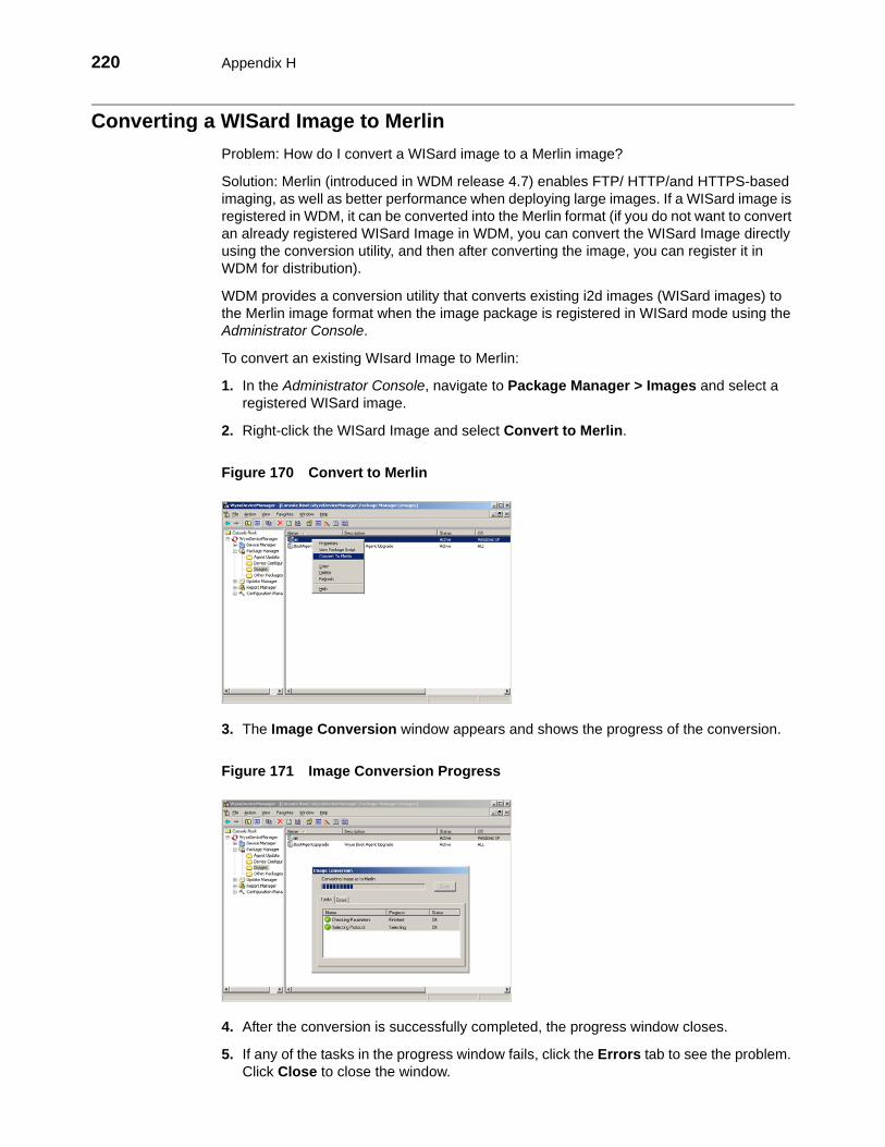
220 Appendix H
Converting a WISard Image to MerlinProblem: How do I convert a WISard image to a Merlin image?
Solution: Merlin (introduced in WDM release 4.7) enables FTP/ HTTP/and HTTPS-based imaging, as well as better performance when deploying large images. If a WISard image is registered in WDM, it can be converted into the Merlin format (if you do not want to convert an already registered WISard Image in WDM, you can convert the WISard Image directly using the conversion utility, and then after converting the image, you can register it in WDM for distribution).
WDM provides a conversion utility that converts existing i2d images (WISard images) to the Merlin image format when the image package is registered in WISard mode using the Administrator Console.
To convert an existing WIsard Image to Merlin:
1. In the Administrator Console, navigate to Package Manager > Images and select a registered WISard image.
2. Right-click the WISard Image and select Convert to Merlin.
Figure 170 Convert to Merlin
3. The Image Conversion window appears and shows the progress of the conversion.
Figure 171 Image Conversion Progress
4. After the conversion is successfully completed, the progress window closes.
5. If any of the tasks in the progress window fails, click the Errors tab to see the problem. Click Close to close the window.

Troubleshooting 221
Error Messages after Uninstalling WDMProblem: After uninstalling WDM and restarting my server, I get error messages.
Solution: If you see Microsoft data execution prevention and IIS error messages after server restart, you must complete these additional steps to remove the RapportFilter entry from IIS manually.
Figure 172 Microsoft data execution prevention message - example
Figure 173 IIS error message - example
1. Open the IIS Web Sites Properties dialog box (according to the IIS documentation for your server version).
Figure 174 Remove the RapportFilter entry from IIS - example
2. On the ISAPI Filters tab, select RapportFilter from the list, click Remove, confirm, and then click OK.
3. After removing the RapportFilter entry from IIS, restart the server. You should no longer see Microsoft data execution prevention and IIS error messages after server restart.

222 Appendix H
This page intentionally blank.

223
Tables1 Routine Device Manager Tasks 122 Routine Package Manager Tasks 363 Routine Update Manager Tasks 584 Routine Report Manager Tasks 725 Protocol Used to Register WDM Packages to Master Software Repository 1046 Protocol Used for WDM Package Updates 1047 Protocol Used for Remote Software Repository Synchronization 1148 Destination Folder Paths 212

Administrators Guide
Wyse Device ManagerTM Release 4.9Issue: 021512
Written and published by: Wyse Technology Inc., February 2012
Created using FrameMaker® and Acrobat®