adopted by city of kelso city council february 1, 2011
TRANSCRIPT

Adopted by City of Kelso City Council February 1, 2011
Effective
February 6, 2011

CCiittyy ooff KKeellssoo EEnnggiinneeeerriinngg DDeessiiggnn MMaannuuaall
Adopted by
City of Kelso City Council February 1, 2011
Effective February 6, 2011
Contents Chapter 1: General Design Requirements Chapter 2: Erosion Control, Clearing and Grading Chapter 3: Streets Chapter 4: Storm Drainage Chapter 5: Water Chapter 6: Wastewater
Appendix A: Procedure for Permit Projects by Private Contract
Appendix B: Longview – Kelso Urban Area Access Management for Roads and Streets
Appendix C: Table 4.1-Summary of Most Common State Flow and Quality Control Credits in Ecology’s SMMWW
Appendix D: Local and State Requirements Flowcharts Appendix E: Design Storm Data Appendix F: Common Onsite Runoff Management BMPs Appendix G: Open Pit Falling Head Infiltration Test
Appendix H: Example Maintenance Agreement and Restrictive Covenant

Chapter 1
General Design Requirements
City of Kelso Engineering Design Manual
February 2011
Chapter 1
General Design Requirements City of Kelso
Engineering Design Manual February 2011
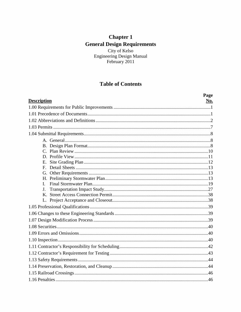
Table of Contents
Page Description No. 1.00 Requirements for Public Improvements ..................................................................................1 1.01 Precedence of Documents ........................................................................................................1 1.02 Abbreviations and Definitions .................................................................................................2 1.03 Permits .....................................................................................................................................7 1.04 Submittal Requirements ...........................................................................................................8
A. General ...........................................................................................................................8 B. Design Plan Format........................................................................................................8 C. Plan Review .................................................................................................................10 D. Profile View .................................................................................................................11 E. Site Grading Plan .........................................................................................................12 F. Detail Sheets ................................................................................................................13 G. Other Requirements .....................................................................................................13 H. Preliminary Stormwater Plan .......................................................................................13 I. Final Stormwater Plan..................................................................................................19 J. Transportation Impact Study........................................................................................27 K. Street Access Connection Permit .................................................................................38 L. Project Acceptance and Closeout.................................................................................38
1.05 Professional Qualifications ....................................................................................................39 1.06 Changes to these Engineering Standards ...............................................................................39 1.07 Design Modification Process .................................................................................................39 1.08 Securities ................................................................................................................................40 1.09 Errors and Omissions .............................................................................................................40 1.10 Inspection ...............................................................................................................................40 1.11 Contractor’s Responsibility for Scheduling ...........................................................................42 1.12 Contractor’s Requirement for Testing ...................................................................................43 1.13 Safety Requirements ..............................................................................................................44 1.14 Preservation, Restoration, and Cleanup .................................................................................44 1.15 Railroad Crossings .................................................................................................................46 1.16 Penalties .................................................................................................................................46

City of Kelso Engineering Design Manual Chapter 1 – General Design Requirements February 2011
1-1
CHAPTER 1 – GENERAL DESIGN REQUIREMENTS
1.00 Requirements for Public Improvements
A. General
The purpose of this document is to set standards for the design and construction of public improvements. These include street, bikeway, drainage, water, and sanitary sewer improvements as required by the development review process, City ordinance, and other City policies adopted by the City. Standards for site grading, erosion control, parking lot, private street, and driveway construction on private property are also contained in these standards. No such work shall commence prior to City approval of the construction plans. Design submitted shall be stamped by a registered professional engineer licensed to practice in the State of Washington, or as otherwise approved by the Director.
All public improvements and private streets, parking lots, sidewalks, and driveways shall be designed and constructed in such a manner as to be readily accessible to and usable by individuals with disabilities as per the requirements of the Americans with Disabilities Act. This includes providing curb ramps at intersections with pedestrian crosswalks to allow a smooth transition between street and sidewalk elevations.
B. Shortened Designation
This City of Kelso Engineering Design Manual shall be cited routinely in the text as the "KEDM."
C. Applicability
The KEDM shall govern all new construction and upgrading of facilities both in the right-of-way and on-site for: transportation-related facilities; storm drainage facilities and stream channel improvements; sewer and water improvements; and park, recreation, and open-space facilities used by the public.
1.01 Precedence of Documents
If there is a conflict between approval documents, the document highest in precedence shall control. The precedence shall be:
First: Permits from other agencies as may be required by law.
Second: Modifications to the KEDM as approved by the Director.
Third: Conditions of approval, facilities review, and site development permit.

City of Kelso Engineering Design Manual Chapter 1 – General Design Requirements February 2011
1-2
Fourth: City of Kelso Ordinances. Fifth: Kelso/Longview Standard Plans and Specification.
Sixth: Plans and details prepared by the design engineer.
Seventh: WSDOT Standards Specifications for Road, Bridge, and Municipal Construction.
Eighth: Reference specifications.
Supplemental written agreements and approved revisions to plans and specifications by the appropriate jurisdiction will take precedence over documents listed above. Detailed plans shall have precedence over general plans. In any event, the determination of the Director shall be final.
1.02 Abbreviations and Definitions
AASHTO American Association of State Highway and Transportation Officials.
AC Asphaltic Concrete (See HMA).
ACI American Concrete Institute.
ADA Americans with Disabilities Act of 1990.
ADT Average Daily Traffic.
All Weather Surface
A gravel or paved surface
ALTA American Land Title Association.
Amenity Amenity is a holistic stormwater approach that incorporates sustainable maintenance and aesthetics into designs that retain or mimic natural processes, and where stormwater itself promotes understanding of stormwater and increases a site’s attractiveness and value.
ANSI American National Standards Institute.
Applicant Any person, firm or corporation applying for public services, or responsible party for a development application.
Appurtenance Any fixed object located adjacent to the roadway and deemed to be a possible safety hazard.
APWA American Public Works Association.

City of Kelso Engineering Design Manual Chapter 1 – General Design Requirements February 2011
1-3
ASTM American Society for Testing and Materials.
AWWA American Water Works Association.
Bicycle A vehicle having two tandem wheels, propelled solely by human power.
Bicycle Facilities
A general term denoting improvements and provisions which accommodate or encourage bicycling, including parking facilities, maps, signs, pathways, bike lanes, widened sidewalks, bikeways, and shared roadways designated for bicycle use.
Bicycle Lane (Bike Lane)
A portion of a roadway, which has been designated by striping, signing and pavement markings for the preferential or exclusive use of bicyclists.
Bicycle Path (Off-Street Pathway)
A paved pathway physically separated from motorized vehicular traffic by an open space or barrier within an independent right-of-way.
Bicycle Route (Bike Route)
A segment of a system of bikeways designated by the jurisdiction having authority with appropriate directional and informational markers, with or without a specific bicycle route number, or as designated on a bicycle map, brochure, or guidebook.
Bikeway Any road, path or way which in some manner is specifically designated as being open to bicycle travel, regardless of whether such facilities are designated for the exclusive use of bicycles or are to be shared with other transportation modes.
BMP Best Management Practice
BMP Manual Volume II of the Stormwater Management Manual for Western Washington.
CARV Combination Air and Vacuum Release Valve.
CBE Crushed base equivalent (CBE) is the number that directly relates the traffic coefficient to the required number of inches of rock for street structural sections.
CBR California Bearing Ratio.
CCCP City of Kelso Cross Connection Control Plan as described in KMC 13.04.060.
CDID #1 Consolidated Diking Improvement District #1
CDID #3 Consolidated Diking Improvement District #3
City City of Kelso.

City of Kelso Engineering Design Manual Chapter 1 – General Design Requirements February 2011
1-4
City Engineer City Engineer for the City of Kelso or their Designee.
Connection The connection of a private or public street, driveway, or alley at the right-of-way line to a public street.
Contractor The agent of the applicant completing the construction activities associated with a given project.
Developer The owner and/or their agents or contractors responsible for a given project.
Development Any improvement, public or private, which requires a land use permit.
Director Director of Public Works or their designee.
DOE Washington State Department of Ecology.
DOE Orange Book
Most recent edition of ‘Criteria for Sewage Works Design’ by the DOE.
DOH Washington State Department of Health.
Drip line The circle that could be drawn on the soil around a tree or shrub directly under the tips of its outermost branches.
Driveway Any access to any property that is not defined under a public or private road.
Ecology Washington State Department of Ecology
Engineer Engineer doing the project design.
EPA U.S. Environmental Protection Agency.
FEMA Federal Emergency Management Agency.
fps Feet per second
Gate Movable barrier designed and constructed to prohibit or limit motor vehicle access from a public street to private property.
GPS Global Positioning System.
HMA Hot Mix Asphalt.
IBC International Building Code with Washington amendments.
IFC International Fire Code with Washington amendments.
IE Invert Elevation.
IMC International Mechanical Code with Washington amendments.

City of Kelso Engineering Design Manual Chapter 1 – General Design Requirements February 2011
1-5
IPC International Plumbing Code with Washington amendments.
Impervious Area
Those hard surface areas located upon real property which either prevent or retard saturation of water into the land surface, as existed under natural conditions pre-existent to development, and cause water to run off the land surface in greater quantities or at an increased rate of flow from that present under natural conditions pre-existent to development. Common impervious area materials include, but are not limited to, asphalt, concrete and gravel.
Intersection Refers to the area jointed by two (2) or more roads intersecting. For approaches of a continuous street at an acute curve or some other angle point with different street names.
KSAC Kelso Stormwater Advisory Committee
Level of Service (LOS)
A quantitative measure of traffic congestion identified by a declining letter scale (A-F) as calculated by the methodology contained in the Highway Capacity Manual Special Report 209 or as calculated by another method approved by the department of public works. LOS “A” indicates free flow of traffic with no delays while LOS “F” indicates jammed conditions or extensive delay.
LID Manual Low Impact Development Manual, Puget Sound Partnership
MR Ecology’s Minimum Requirements
Multi-Use Trail
A pathway designated for pedestrian or bicycle use.
MUTCD Manual on Uniform Traffic Control Devices.
NEC National Electric Code with Washington amendments.
NPDES National Pollutant Discharge Elimination System
OS and Y Outside Stem and Yoke.
OSHA Occupational Safety and Health Administration.
Parking Lot Any area intended to accommodate parked vehicles for free or for a fee and not accessory to single-family residences.
Peak Hour Trips
The existing or calculated total vehicular trips entering and leaving a development during the peak hour of trip generation for the development, sometimes referred to as Design Hour Volume (DHV).
Phase II Permit
The City of Kelso’s Western Washington Phase II Municipal Stormwater Permit

City of Kelso Engineering Design Manual Chapter 1 – General Design Requirements February 2011
1-6
Private Roadway
Any vehicular access way, designed or intended to serve three or more parcels or dwelling units or any commercial business which has not been dedicated and accepted as a public roadway.
Procedures Manual
City of Kelso Procedures Manual for Construction of Public Improvements, Procedure for Permit projects by Private Contract.
Professional Engineer
An engineer licensed in the State of Washington
PRV Pressure Reducing Valve.
PSM Storm Water Management Manual for the Puget Sound Basin.
RCW Revised Code of Washington.
ROW Right-of-Way.
Securities Bonds, retainers, cash deposits, assigned savings, or another type of guarantee used to guarantee the performance of or correct deficient work.
Sidewalk The portion of a street designed for preferential use by pedestrians.
Signal Spacing The required distance between intersections with traffic signals.
SMMWW 2005 Stormwater Management Manual for Western Washington, Ecology
Standard Drawings
The latest edition of the City of Kelso/Longview Standard Plans and Specifications.
Street A public or private way, which affords the principal means of access to abutting property.
SWPPP Stormwater Pollution Prevention Plan
TCDH Traffic Control Device Handbook.
Traffic Coefficient
A number used in determining the structural section of a street.
Trail In the context of the General Plan - “Trail” is synonymous with Bicycle Path (off-street pathway).
Trip Generation
The most recent calculated trip rates (either calculated by average or formula), published by the Institute of Traffic Engineers or other transportation engineering analysis proposed by an Applicant and deemed appropriate by the Director.

City of Kelso Engineering Design Manual Chapter 1 – General Design Requirements February 2011
1-7
Traffic Engineer
An individual licensed by the State of Washington to practice professional engineering who has been retained by the City or others to design roadway improvements, including utilities.
UL Underwriter’s Laboratory.
Unimproved Surface
Any surface that is not maintained or where natural vegetation is expected to grow taller than 6 inches.
Unsignalized Access Spacing
The distance between intersections that do not have a traffic signal.
Unsignalized Spacing
The distance between intersections that do not have a traffic signal.
WAC Washington Administrative Code.
WSDOT Washington State Department of Transportation
WWM Stormwater Management Manual for Western Washington.
Wetlands Those areas that are inundated or saturated by surface or ground water at a frequency and duration sufficient to support, and that under normal circumstances do support, a prevalence of vegetation typically adapted for life in saturated soil conditions. Wetlands generally include swamps, marshes, bogs, and similar areas. Identification and delineation of jurisdictional wetlands and wetland boundaries shall be done by a qualified biologist using applicable State and Federal guidelines.
WSDOT The Washington State Department of Transportation.
WSDOT Standard Specifications
The latest edition of the “Standard Specifications for Road, Bridge, and Municipal Construction” as published by the Washington State Department of Transportation and the American Public Works Association.
WSM Water System Plan for the Longview-Kelso Urban Area 1.03 Permits
Permits, approvals, or agreements are required by the City and some-times other jurisdictions, prior to initiating any construction or demolition work elements described within these Standards. The majority of work covered under these Standards will require multiple permit authority review and approvals. Several types of permits and approvals require prior approval from the authority before a building or other substantial permit can be issued. Any questions regarding information about permits, approvals, and agreements should be directed to the
City of Kelso Engineering Design Manual Chapter 1 – General Design Requirements February 2011
1-8
Director. Grading permits, separate from construction plan approval, for developments are discouraged but may be issued at the discretion of the Director between May 1st and October 1st, provided that the Director may extend or shorten this time period on a case by case basis depending on actual weather conditions. The first review of the development’s construction plans shall be completed prior to submittal of the grading permit application to the City.
1.04 Submittal Requirements
A. General
1. Submittal requirements consist of design plans, grading plans (where required),
erosion control plans (where required), drainage calculations, geotechnical reports, and other information as required. Letters of transmittal referencing the project name shall accompany all submittals.
2. The WSDOT Standard Specifications are hereby adopted and incorporated as part
of this document by reference except as modified herein.
B. Design Plan Format
1. The plans shall be electronically drafted and submitted on 22" x 34" sheets, landscape format.
2. Vicinity maps shall be located on the first sheet of all plans and shall show the
location of the project in respect to the nearest major street intersection. 3. A north arrow and scale bar shall be shown on each plan view sheet of the plans
and adjacent to any other drawing, which is not, oriented the same as other drawings on the sheet.
4. Civil Site Development Plans shall be organized as follows:
a. Title sheet to include:
(i) Project name (ii) Vicinity map (iii) Name and mailing address of Applicant/Owner, engineering firm,
survey firm, and geotechnical engineer (iv) City Standard Construction Notes (v) Index of sheets (vi) Notice to excavators (vii) Legend that provides the name and symbol for all symbols used on
the subsequent pages

City of Kelso Engineering Design Manual Chapter 1 – General Design Requirements February 2011
1-9
(viii) Four in by four inch space in the lower right corner for the City of Kelso’s approval stamp.
b. Composite utility plan: include existing public and private utilities, and proposed public improvements.
c. Sanitary sewer and water, including fire hydrant locations. d. Street and storm sewer, showing existing and proposed contours at 2-foot
intervals. e. Grading and erosion control plan with maximum contour intervals of 5’ for
slopes over 10%, 2 feet for slopes 3% to 10% and ½ feet for slopes less than 3%. Contours shall extend offsite a minimum of 50 feet. This sheet shall also note the source of information, date of field work, and location of original document.
f. Approved preliminary plat (if it's a subdivision). g. Landscape plan including sidewalks, bikeways, retaining walls,
landscaping, irrigation, and lighting. h. Signing and striping plan.
5. The scale shall be 1-inch = 5 feet vertically, and 1-inch = 20 feet horizontally for
all drawings. A scale of 1-inch = 10 feet may be used for more detailed drawings such as intersection drawings. The composite utility plan may be at a smaller scale if needed. Scale shall be shown with north arrow and within a title block. All scales shall be as designated above unless otherwise approved by the Director.
6. Letter size shall not be smaller than 0.10 of an inch high. 7. The location and elevation of a National Geodetic Survey, United States
Geological Survey, Cowlitz County, or City of Kelso bench mark shall be shown. No other datum shall be used without permission of the City. Temporary control bench marks and elevations shall also be shown on the plans.
8. A title block shall appear on each sheet of the plan set and shall be placed in the
lower right-hand corner of the sheet across the right-hand edge of the sheet. The title block shall include the name of the project, the engineering firm, the Owner, the sheet title, and the sheet number.
9. The seal of the registered Washington Professional Engineer responsible for preparation of the plans shall appear on each sheet.
10. The description and date of all revisions to the plans shall be shown on each sheet affected, and shall be approved and dated by the registered Professional Engineer of record as evidenced by an original signature or initial.

City of Kelso Engineering Design Manual Chapter 1 – General Design Requirements February 2011
1-10
11. Through use of standard drafting symbols, indicate the location and direction of view for all sections.
12. The following statement shall appear on the cover sheet of all plans at a location immediately above or below the development engineer's professional stamp:
“I hereby certify that these plans, and related design, were prepared in conformance with the City of Kelso's Engineering Design Manual. I acknowledge that City approval of these documents does not transfer liability.”
C. Plan View
Plan views shall show the following:
1. Right-of-way, property, tract, and easement lines (existing and proposed).
2. Subdivision name, lot numbers, street names, and other identifying labels.
Subdivision and street names are subject to the approval of the City Planning Director, Fire Chief, and Director.
3. Location and stationing of existing and proposed street center lines and curb faces.
4. Horizontal alignment and curve data of street center lines and curb returns including bearings along centerline.
5. Existing underground utilities and trees over 6-inches in diameter within the construction limit.
6. Location of existing buildings, wells, septic tanks, drain fields, fuel tanks, and any other buried structures.
7. Location, stationing, and size of all mains and service lines for storm drainage, sanitary sewer, and water; and location of all fire hydrants. Stationing shall be located in relationship to the street stationing at all manholes or other key locations.
8. Match lines with sheet number references.
9. Provisions for cross-connection control must be clearly shown on the plans, including any retro-fitting of existing water service connections and existing auxiliary water supplies, conversions to City of Kelso water service that are required as a condition of development approval, upgrading of existing service connections by replacement of same, and any other cross connection control required by state and local rules and codes.

City of Kelso Engineering Design Manual Chapter 1 – General Design Requirements February 2011
1-11
10. Street stationing to be noted at a minimum of 100-foot stations.
11. Top of curb elevations along curb returns at quarter-delta's and 100-foot stations.
12. Location of the low points of street grades and curb returns.
13. Sidewalk locations. This shall include ramps, transitions in location or width,
and relationship with driveways. It shall be shown with hatching what sidewalk is proposed to be constructed with the street and what sidewalk is proposed to be constructed with the buildings.
14. Crown lines along portions of streets transitioned from one typical section to another.
15. Centerline stationing of all intersecting streets.
16. Location and description of existing survey monuments, including but not limited to: section corners, quarter corners, donation land claim corners, and City bench marks.
17. Location of proposed street intersection monument boxes.
18. FEMA designated 100-year flood plains and flood ways, or areas of flooding during a 100-year storm event.
19. Wetland areas and storm water quality undisturbed corridors (buffer strips).
20. Legend. 21. Applicant's name, address, and phone number.
22. Any additional information that the City deems necessary.
D. Profile View
Profile Views shall show the following:
1. Stationing, elevations, vertical curve data (including curve k factors), and slopes
for center of streets or top of curbs. For off-set or super elevation cross-sections, both curbs shall be profiled. Where curbs are not to be constructed, center line of street and ditch inverts shall be shown.
2. Original ground along the center line, and if necessary at the edges of the right-
City of Kelso Engineering Design Manual Chapter 1 – General Design Requirements February 2011
1-12
of-way if grade differences are significant.
3. Center line, top of curb, and gutter flow lines of existing streets for a distance of at least 300 feet each way at intersections with proposed streets. For stub streets that may be extended in the future, the vertical alignment shall be designed for at least 300 feet beyond the scope of the proposed construction, unless otherwise approved by the Director. At the discretion of the Director, additional design information concerning the vertical and horizontal alignment of future street extensions may be required.
4. Vertical alignment of streets, including existing center line monumentation.
5. The top of curb for all cul-de-sacs, eyebrows, and curb returns.
6. All proposed drainage facilities; all invert and top elevations, slopes, materials, bedding, and backfill.
7. Existing drainage facilities, including off-site facilities, upstream and downstream that affect the design (e.g. downstream restrictions that back water onto project site). In addition, base flood elevations shall be shown on the profile.
8. Profiles for ditch and creek flowlines shall extend a minimum of 200 feet beyond the project, both upstream and downstream with typical cross sections at 50-foot intervals, unless otherwise approved by the Director.
9. Designate structures using alpha or numeric labels on profiles to correspond to plan view notation.
10. Profile for existing and proposed storm, sanitary, and water mains. 11. All existing and proposed sanitary, water, storm lines, and other utilities crossing
the profile.
E. Site Grading Plan
The City of Kelso requires a site-grading plan as part of the application for any development that involves the excavation or fill of greater than 50 cubic yards of material. Grading contours (existing & proposed) shall be at no more than 2-foot intervals. Existing contours shall extend off-site a minimum of 50 feet. This sheet shall also note source of information, date of fieldwork, and location of original document.
All soil disturbing construction activity must adhere to the requirements of Chapter 2.

City of Kelso Engineering Design Manual Chapter 1 – General Design Requirements February 2011
1-13
A detailed erosion control plan shall be shown in conjunction with the site-grading plan.
F. Detail Sheets
Detail sheets shall be provided as part of the Site Development Plans. The detail sheet shall show all City Standard Details and special details necessary for the project.
All Details shall be full size.
G. Other Requirements
Other information to be shown on the construction drawings or other submittals includes: 1. The design elements such as:
a. Street classification;. b. Design speed; c. Super elevation;
2. Structural construction plans and the necessary calculations stamped by a
structural engineer shall be submitted for proposed structures, as determined by the Director (i.e. walls, box culverts, bridges). A letter from the engineer approving installation of the structure shall be submitted prior to as-built approval.
3. Any additional information that the Director deems necessary to review the plans and assure compliance with design standards.
H. Preliminary Stormwater Plan
1. Purpose. The purpose of the preliminary stormwater plan is to allow the City to
determine whether a proposal will meet the requirements of these standards Projects creating ≥5,000 square feet of new or replaced impervious surfaces must include a preliminary stormwater plan. The preliminary stormwater plan submittal shall consist of:
1) A preliminary development plan. 2) A preliminary technical information report (Stormwater
Report) prepared in the standardized format described in the sections below.

City of Kelso Engineering Design Manual Chapter 1 – General Design Requirements February 2011
1-14
The preliminary stormwater plan shall identify how stormwater runoff, that originates on the site or flows through the site, is currently controlled and how this will change with the proposed development or redevelopment project. The project engineer shall include a statement that all the required information is included in the preliminary stormwater plan and that the proposed stormwater facilities are feasible. All plans, studies, and reports that are part of the preliminary and final stormwater plans shall be signed and dated by the registered soil scientist(s) and/or the professional civil engineer(s) (registered in the state of Washington) responsible for preparation of the report.
2. To ensure adequate public review and avoid multiple reviews of preliminary reports by City staff, the preliminary stormwater plan shall not be significantly modified after public notice of the final SEPA determination without issuance of a new SEPA determination.
3. Timing. A preliminary stormwater plan shall be submitted with a land use application.
4. Preliminary Development Plan
The preliminary development plan shall consist of 22-inch x 34-inch drawings and may be included in the design plans. The preliminary development plan shall show the character of the existing site and proposed features, including but not limited to:
1. Existing and proposed property boundaries, easements, and rights-of-way. 2. Existing and proposed contours with a 2-foot maximum contour interval,
unless the Director determines a lesser interval is sufficient to show drainage patterns and basin boundaries.
3. Offsite areas contributing runoff to the site. 4. Natural and manmade drainage features adjacent to the site, including
existing and proposed (if known) stormwater facilities. 5. Existing onsite water wells, known agricultural drain tiles, areas of potential
slope instability, structures, utilities, and septic tanks and drain fields. 6. Location of the 100-year floodplain, floodways, and shoreline management
area limits on the site. 7. Existing water resource features on and adjacent to the site, including
streams, wetlands, springs, sinks, and stormwater facilities. 8. Existing and proposed drainage flow routes for each threshold discharge area
(TDA) to and from the site, including bypass flows. 9. Proposed location of structural source control BMPs, where applicable. 10. Point of discharge locations from the proposed project site that preserve the
natural drainage patterns and existing outfall locations.

City of Kelso Engineering Design Manual Chapter 1 – General Design Requirements February 2011
1-15
11. Areas of the project site where onsite stormwater management BMPs will be effectively implemented, including low impact development BMPs. The plan shall show the areas of retained native vegetation, required flow lengths, and vegetated flow paths for proper implementation of these BMPs.
12. All existing drainage facilities, including structural water quality or flow control BMPs and conveyance systems.
13. Existing and proposed pollution-generating pervious surfaces (PGPS), including lawn, landscaped areas, and pasture areas.
14. Existing areas of the site predominantly covered by native vegetation (i.e., native trees, shrubs, and herbaceous plants as defined by the Washington State Department of Ecology [Ecology]) and areas of native vegetation to be preserved under proposed conditions.
15. Approximate location and size of proposed runoff treatment and flow control facilities implemented.
16. The delineated wetland boundary (for sites that discharge stormwater to a wetland, either directly or indirectly through a conveyance system.
17. A conceptual grading plan that verifies the constructability of a stormwater facility (for sites with slopes greater than 5 percent).
18. The Director may require additional site or vicinity information if needed to determine the feasibility of the stormwater proposal.
5. Preliminary Stormwater Report (Stormwater Report)
The preliminary Stormwater Report shall contain all technical information and analyses necessary to determine that the proposed stormwater facilities are feasible. The required contents of the preliminary Stormwater Report are identified below.
Table of Contents 1. List of section headings and their respective page numbers. 2. List of tables with page numbers. 3. List of figures with page numbers. 4. List of attachments, numbered. 5. List of references. Map Submittals All maps shall contain a scale and north arrow. 1. Vicinity Map: All vicinity maps shall clearly show the project site. 2. Soils Map: The soils map shall show soils within the contributing area that
drains to the site itself. Soils maps may be obtained from the Washington soil survey data as available on the NRCS website (http://soils.usda.gov/).

City of Kelso Engineering Design Manual Chapter 1 – General Design Requirements February 2011
1-16
If the maps do not appear to accurately represent the soils on the site, the applicant is responsible for verifying the actual soils on the site.
3. Other Maps: The following additional maps shall be required in the situations noted: – Wellhead Protection. If the site lies within the 10-year time-of-travel zone
of a public water supply well or within a Category I or II critical aquifer recharge area (CARA), maps showing all of the zones of contribution that overlap the site are required.
– Floodplains. If a floodplain mapped by the Federal Emergency Management Agency (FEMA) exists on or adjacent to the site, a map showing the floodplain is required.
– Shoreline Management Area. If the site requires a shoreline permit, a map showing the boundary of the shoreline management area in relation to the site is required.
Section A – Project Overview 1. Describe the site location. 2. Describe the topography, natural drainage patterns, vegetative ground cover,
and presence of critical areas. Critical areas that receive runoff from the site shall be described to a minimum of ¼ mile away from the site boundary.
3. Identify and discuss existing onsite stormwater systems and their functions. 4. Identify and discuss site parameters that influence stormwater system
design. 5. Describe drainage to and from adjacent properties. 6. For agricultural sites with drain tiles, discuss the impact of construction on
the drain tiles, site drainage, and the impact of the drainage tiles on proposed stormwater facilities.
7. Describe adjacent areas, including streams, lakes, rivers, wetland and buffer areas, residential areas, and roads that might be affected by the construction project.
8. Generally describe proposed site construction, size of improvements, and proposed methods of mitigating stormwater runoff quantity and quality impacts.
Section B – Minimum Requirements If applicable, describe the land-disturbing activity and document the applicable minimum requirements for the project site. (See Chapter 4 of this manual for guidance.) Include the following information in table format: 1. The amount of existing impervious surface. 2. The amount of new impervious surface. 3. The amount of replaced impervious surface. 4. The amount of native vegetation converted to lawn or landscaping.

City of Kelso Engineering Design Manual Chapter 1 – General Design Requirements February 2011
1-17
5. The amount of native vegetation converted to pasture. 6. The total amount of land-disturbing activity. Provide a statement that confirms the minimum requirements that will apply to the development activity. For land-disturbing activities where minimum requirements 1 through 10 must be met: 1. Provide the amount of effective impervious area in each TDA, and
document through an approved continuous runoff simulation model (e.g., the Western Washington Hydrologic Model [WWHM]) the increase in the 100-year flood frequency from pre-developed to developed conditions for each TDA.
2. List the TDAs that must meet the runoff control requirements listed in Minimum Requirement 6.
3. List the TDAs that must meet the flow control requirements listed in Minimum Requirement 7.
4. List the TDAs that must meet the wetlands protection requirements listed in Minimum Requirement 8.
Section C – Soils Evaluation 1. Describe the site’s suitability for stormwater infiltration for flow control,
runoff treatment, and low impact development (LID) measures. 2, Identify water table elevations, flow directions (where available), and data
on seasonal water table fluctuations with minimum and maximum water table elevations where these may affect stormwater facilities.
3. Identify and describe soil parameters and design methods for use in hydrologic and hydraulic design of proposed facilities.
4. Report findings of testing and analysis used to determine the infiltration rate.
5. Where unstable or complex soil conditions exist that may significantly affect the design of stormwater facilities, the Director may require a preliminary soils report that addresses stormwater design considerations arising from soil conditions. The preliminary soils report shall be prepared by a registered professional engineer, licensed in the state of Washington, proficient in geotechnical investigation and engineering or a registered soil scientist. The preliminary soils report shall include a soils map developed using the criteria set in the NRCS National Soil Survey Handbook (NRCS 2007) and the SCS Soil Survey Manual (SCS 1993), at a minimum scale of 1:5,000 (12.7 inch/mile).
Section D – Source Control If the development activity requires source control, identify the source control BMPs to be used with the land-disturbing activity.

City of Kelso Engineering Design Manual Chapter 1 – General Design Requirements February 2011
1-18
Section E – Onsite Stormwater Management BMPs 1. On the preliminary development plan or other maps, show the site areas
where onsite stormwater management BMPs will be effectively implemented. If applicable, the plan must show the areas of retained native vegetation and required flow lengths and vegetated flow paths, as required for proper implementation of each onsite stormwater BMP. Arrows must show the stormwater flow path to each BMP.
2. Identify and describe geotechnical studies or other information used to complete the analysis and design of each onsite stormwater BMP.
3. Identify the criteria (and their sources) used to complete analyses for each onsite stormwater BMP.
4. Describe how design criteria will be met for each proposed onsite stormwater management BMP.
5. Describe any onsite application of LID measures planned for the project. Provide a plan that shows the proposed location and approximate size of each LID facility.
6. Identify and describe any assumptions used to complete the analysis. 7. Describe site suitability, including hydrologic soil groups, slopes, area of
native vegetation, and adequate location of each BMP. Section F – Runoff Treatment Analysis and Design 1. Document the level of treatment required. 2. Provide background and description to support the selection of the
treatment BMPs being proposed. Include an analysis of initial implementation costs and long-term maintenance costs.
3. Identify geotechnical or soils studies or other information used to complete the analysis and design.
4. Identify the BMPs used in the design, and their sources. 5. Summarize the results of the runoff treatment design and describe how the
proposed design meets the requirements of the SMMWW. 6. Provide a table that lists the amount of pollution-generating pervious
surfaces (PGPS) and pollution-generating impervious surfaces (PGIS). Section G – Flow Control Analysis and Design 1. Identify the site’s suitability for stormwater infiltration for flow control,
including tested infiltration rates, logs of soil borings, and other information.
2. Identify and describe geotechnical or other studies used to complete the analysis and design.
3. If infiltration cannot be provided for flow control, provide the following additional information:

City of Kelso Engineering Design Manual Chapter 1 – General Design Requirements February 2011
1-19
– Identify the areas where flow control credits can be obtained for dispersion, LID, or other measures, per the requirements in the SMMWW.
– Provide the approximate sizing and location of flow control facilities for each TDA, per Volume III of the SMMWW.
– Identify the criteria (and their sources) used to complete the analyses, including pre-developed and post-developed land use characteristics.
– Include and reference all hydrologic computations, equations, graphs, and any other aids necessary to clearly show the methodology and results.
– Include all maps, exhibits, graphics, and references used to determine existing and developed site hydrology.
4. Submit electronic copies of the WWHM (.wdm, .prj, .usi) project files upon request, if applicable.
Section H – Wetlands Protection For projects with stormwater discharges to a wetland and/or wetland buffer, either directly or indirectly through a conveyance system, the preliminary Stormwater Report shall describe wetland protection measures to be implemented. The narrative shall describe the measures that will maintain the hydrologic conditions, hydrophytic vegetation, and substrate characteristics necessary to support existing and designated uses.
I. Final Stormwater Plan
A. Purpose
The final stormwater plan shall provide final engineering design and construction drawings for the stormwater aspects of a proposed new development or redevelopment project. The final stormwater plan shall be submitted and approved by the Director before construction of the development can begin.
B. Final Stormwater Plan Submittal
The final stormwater plan submittal shall include the following:
1. Any conditions of approval from the land use process. 2. Any easements, covenants, or agreements necessary to permit
construction. 3. Final engineering plans that provide sufficient detail to allow
construction of the stormwater facilities. These plans shall be stamped, signed, and dated by the engineer(s), registered in the state of Washington, responsible for hydrologic, hydraulic, geotechnical, structural, and general civil engineering design and by the project
City of Kelso Engineering Design Manual Chapter 1 – General Design Requirements February 2011
1-20
engineer responsible for the preparation of the final stormwater plan. The final engineering plan shall show all utilities to ensure that conflicts between proposed utility lines do not exist.
4. The approved preliminary stormwater plan, with an explanation of any differences between the design concepts included in the preliminary and final stormwater plans. If a final stormwater plan differs from the approved preliminary stormwater plan in a manner that, in the opinion of the Director, raises material water quality or quantity control issues, it shall require another SEPA determination (if subject to the State Environmental Policy Act [SEPA]) and a plat alteration.
5. A final development plan (which may be a part of the final engineering plans or a separate plan). See the requirements identified below.
6. A final technical information report (Stormwater Report). See the requirements identified below.
7. A construction stormwater pollution prevention plan (SWPPP). See Section 3.5 below.
Final Development Plan
The final development plan shall be consistent with the preliminary development plan and may be combined with the final engineering plans. In addition to the information required in the preliminary development plan, the final plan requires the following information:
1. Threshold discharge area (TDA) delineations, and total impervious and
pervious area delineations and acreages by TDA. 2. The acreage of pollution-generating pervious surfaces (PGPS) and
pollution-generating impervious surfaces (PGIS) used in the hydraulic/hydrologic calculations both onsite and offsite that contribute surface runoff.
3. Directions and lengths of overland, pipe, and channel flow. 4. Outfall points from each TDA and overflow routes for the 100-year
storm. 5. Onsite conveyance systems, including pipes, catch basins, channels,
ditches, swales, and culverts. 6. Primary flow path arrows for drainage under developed conditions, with
the calculated flow rates. Cross-reference the flow rates to the hydrological model output file used to calculate the flow rates.
7. Approved location for storm runoff from the building lots. 8. The Director may require additional site or vicinity information if
needed to determine the feasibility of the stormwater proposal.

City of Kelso Engineering Design Manual Chapter 1 – General Design Requirements February 2011
1-21
Final Stormwater Report
The final Stormwater Report shall be a comprehensive report, supplemental to the final engineering plans, that contains all technical information and analyses necessary to complete final engineering plans based on sound engineering practices and appropriate geotechnical, hydrologic, hydraulic, and water quality design.
The final Stormwater Report shall be stamped, signed, and dated by the professional engineer(s), registered in the state of Washington, responsible for hydrologic, hydraulic, geotechnical, structural, and general civil engineering design.
The required contents of the final Stormwater Report, which is part of the final stormwater plan, are identified below.
Table of Contents
See the preliminary Stormwater Report requirements.
Map Submittals
See the preliminary Stormwater Report requirements.
Section A – Project Overview
Provide the information from the preliminary Stormwater Report, with the following additional elements:
1. Reference the conceptual design proposed in the preliminary stormwater plan.
2. Identify revisions to the conceptual design contained within the final engineering plans.
3. Provide a narrative of how the goals of the amenity criteria are or are not satisfied.
Section B – Minimum Requirements
If applicable, provide the information from Section B of the preliminary Stormwater Report, revised as necessary for the final design. Confirm the applicable minimum requirements identified in the preliminary Stormwater Report. For land-disturbing activities where minimum requirements 1 through 9 must be met, provide the required information listed in Section B of the preliminary Stormwater Report, revised to reflect the final design.

City of Kelso Engineering Design Manual Chapter 1 – General Design Requirements February 2011
1-22
Section C – Soils Evaluation
See the preliminary Stormwater Report requirements.
Section D – Source Control
See the preliminary Stormwater Report requirements.
Section E – Onsite Stormwater Management BMPs
Provide the information from the preliminary Stormwater Report, with the following additional elements:
1. Reference the conceptual design proposed in the preliminary stormwater
plan. 2. Identify revisions to the conceptual design contained within the final
engineering plans. 3. For bioretention systems, provide the following:
a. The proposed soil matrix for the facility. b. The planting plan, listing proposed plant types and locations. c. Detail drawings, including the following:
– If an underdrain is used, show drain rock, pipe, and filter fabric specifications.
– All stormwater piping associated with the facility, including catch basin, pipe materials, sizes, slopes, and invert elevations.
– Rain garden width, length, side slopes, and maximum design water depth.
– Irrigation system, if installed. – Designs for any retaining walls proposed. Structural walls shall
meet City building permit requirements. 4. For porous pavements, provide the following:
a. Supporting design calculations showing adequate infiltration rates to accommodate flows from all impervious surfaces directed onto any porous pavement.
b. Geotextile specification. c. Base material gradation. d. Asphalt or concrete mix design and void calculations. e. Acceptance test procedures. f. Detail drawings, including the following:
– Geotextile – Base material – Asphalt or concrete layer

City of Kelso Engineering Design Manual Chapter 1 – General Design Requirements February 2011
1-23
5. For reversed slope sidewalks, show the following: – Details on the planting plan for any areas receiving water from reversed
slope sidewalks. 6. Describe how the project will fully implement required BMP T5.13,
Soil Quality and Depth.
Section F – Runoff Treatment Analysis and Design
For land-disturbing activities where runoff treatment facilities are required, provide the information from the preliminary Stormwater Report, with the following additional elements:
1. Reference the conceptual runoff treatment design proposed in the
preliminary stormwater plan. 2. Identify revisions to the conceptual runoff treatment design contained in
the preliminary stormwater plan. 3. Complete a detailed analysis and design of all proposed runoff treatment
system elements, in accordance with Volume V of the WWM. Reference runoff treatment system elements to labeled points shown on the site location map or final development plan.
4. Include and reference all computations, equations, charts, nomographs, detail drawings, and other tabular or graphic aids used to design water quality system elements in the technical appendix.
5. Summarize the results of the runoff treatment design, and describe how the proposed design meets the requirements of the SMMWW.
Section G - Flow Control Analysis and Design
For land-disturbing activities where flow control facilities are required:
1. Identify revisions to the conceptual design proposed in the preliminary stormwater plan.
2. Identify initial conditions, including stream base flows, beginning water surface elevations, hydraulic or energy grade lines, initial groundwater elevations, beginning storage volumes, and other data or assumptions used to complete the analyses of initial conditions. Reference the sources of information.
3. Describe any assumptions used to complete the analysis, including flow credits through the use of onsite stormwater BMPs or LID measures.
4. Complete a detailed hydrologic analysis for existing and developed site conditions, in accordance with the requirements of Chapter 2, Volume III of the SMMWW, using an approved continuous runoff simulation model. Compute pre-developed and developed flow durations for all

City of Kelso Engineering Design Manual Chapter 1 – General Design Requirements February 2011
1-24
subbasins. Provide an output table from the continuous flow model, including the following:
a. Flow rates for the 2, 10, and 100-year return periods for pre- developed and developed conditions.
b. A table listing the pass/fail rates for each flow level where duration statistics were calculated.
c. A graph showing the flow rate on the y axis and percent time exceeding on the x axis for pre-developed conditions and post-developed mitigated conditions, from 50 percent of the 2-year through the 50-year flow rate.
5. Provide a hydraulic analysis of pipes and/or channels that lead to and/or from the outlet structure. The analysis should confirm the capacity of pipes and channels to convey the peak flow rates for the 2, 10, 50, and 100-year return period flow rate with the water surface elevation of the pond at the elevation for those return period flow rates.
6. Submit electronic copies of the WWHM (.wdm, .prj, .usi) project files to allow reviewers to run the model and confirm the model results.
7. Refer to labeled points shown on the site location map and development plan.
8. Include and reference all hydrologic and hydraulic computations, equations, rating curves, stage/storage/discharge tables, graphs, and any other aids necessary to clearly show the methodology and results.
9. Include all maps, exhibits, graphics, and references used to determine existing and developed site hydrology.
Section H - Flow Control System Plan
1. Provide an illustrative sketch of the flow control facility and its appurtenances.
2. Show basic measurements necessary to confirm storage volumes. 3. Show all orifice, weir, and flow restrictor dimensions and elevations. 4. The sketch shall correspond with final engineering plans. Alternatively,
a final site grading plan that incorporates the above information may be included as an attachment to the final stormwater plan.
5. Provide electronic copies of the drawings used for analysis, measurement, and design inputs for the hydrologic analysis submitted with the final drawing in one of the following approved file formats: Portable Document Format (.pdf) or AutoCAD (.dwg, .dxf).
Section I – Wetlands Protection
For projects with stormwater discharges to a wetland or wetland buffer, either directly or indirectly through a conveyance system, the Stormwater Report shall describe wetland protection measures to be implemented, in accordance with

City of Kelso Engineering Design Manual Chapter 1 – General Design Requirements February 2011
1-25
Minimum Requirement 8. The narrative shall describe the measures that will maintain the hydrologic conditions, hydrophytic vegetation, and substrate characteristics necessary to support existing and designated uses.
Section J – Other Permits
Construction of roads and stormwater facilities may require additional permits from other agencies. These permits may contain requirements that affect the design of the stormwater system. Approved permits that are critical to the feasibility of the stormwater facility design shall be included in this section.
Section K – Conveyance Systems Analysis and Design
1. Reference the conceptual drainage design proposed in the preliminary stormwater plan.
2. In the technical appendix, include and reference all computations, equations, charts, nomographs, detail drawings, and other tabular or graphic aids used to design water quality system elements.
3. Identify revisions to the conceptual drainage design contained in the preliminary stormwater plan.
4. Identify the criteria used to complete the analyses and their sources. 5. Identify and discuss initial conditions, including stream base flows,
beginning water surface elevations, hydraulic or energy grade lines, beginning storage elevations, and other data or assumptions used to complete the analyses of initial conditions. Reference the sources of information.
6. Describe any assumptions used to complete the analyses. 7. Complete a detailed hydraulic analysis of all proposed collection and
conveyance system elements and existing collection and conveyance elements, including outfall structures and outlet protection that influence the design or are affected by the proposal, in accordance with Section 4.05 of these standards. Identify, compute, reference, verify, summarize and tabulate the following:
a. Design flows and velocities and conveyance element capacities for all conveyance elements within the development.
b. The 10-year recurrence interval stage for detention facility outfalls. Provide stage-frequency documentation from WWHM.
c. The existing 100-year floodplain elevations and lateral limits for all channels, and no net loss of conveyance or storage capacity from development.
d. The conveyance system elements to labeled points shown on the site location map or development plan.
e. The capacity of each conveyance system element to convey design flow and discharge at non-erosive velocities and the capacity of the

City of Kelso Engineering Design Manual Chapter 1 – General Design Requirements February 2011
1-26
onsite conveyance system to convey design flows that result from ultimate build-out of upstream areas.
f. All hydraulic computations, equations, pipe flow tables, flow profile computations, charts, nomographs, detail drawings, and other tabular or graphic aids used to design and confirm the performance of conveyance systems.
g. The results of system analyses, and how the proposed design meets the requirements of these standards.
Section L – Offsite Analysis
If applicable, provide the results of an offsite analysis prepared in accordance with Chapter 4 (Offsite Analysis and Mitigation) of this manual (see exemptions in Chapter 4.)
Section M—Approval Conditions Summary
List each preliminary approval condition related to stormwater control, wetlands, wetland buffers, floodplains, and other water-related issues and explain how the final design addresses or conforms to each condition.
Section N – Special Reports and Studies
Where site-specific characteristics, such as critical areas as described in the KMC, present difficult drainage and water quality design problems, the Director may require additional information or the preparation of special reports and studies that further address the specific site characteristics, the potential for impacts associated with the development, and the measures that would be implemented to mitigate impacts. Special reports shall be prepared by professionals with expertise in the particular area of analysis, who shall date, sign, stamp, and otherwise certify the report. Subjects of special reports may include, but are not be limited to:
1. Geotechnical 2. Wetlands 3. Floodplains and floodways 4. Groundwater 5. Structural design 6. Fluvial geomorphology (erosion and deposition) All special reports and studies shall be included in the technical appendix.

City of Kelso Engineering Design Manual Chapter 1 – General Design Requirements February 2011
1-27
Section O – Groundwater Monitoring Program
Where required, a groundwater monitoring program shall be included in the final stormwater plan. The groundwater monitoring program shall be prepared by a person with expertise in groundwater contamination investigation, prevention, and monitoring and shall clearly describe a comprehensive groundwater testing and evaluation program designed to ensure compliance with federal and state of Washington laws and these standards. The Director will review proposed groundwater monitoring programs on a site-specific basis.
Section P – Maintenance and Operations Manual
The project engineer shall attach the maintenance manual required in Chapter 4 of this Manual.
Technical Appendix
All Stormwater Reports shall contain a technical appendix that includes all computations completed in the preparation of the Stormwater Report, together with copies of referenced data, charts, graphs, nomographs, hydrographs, stage-storage discharge tables, maps, exhibits, and all other information required to clearly describe the stormwater flow control and runoff treatment design for the proposed development activity. The format of the technical appendix shall follow as closely as possible the section format of the Stormwater Report and shall be adequately cross-referenced to ensure that the design may be easily followed, checked, and verified. The technical appendix shall also contain all special reports and studies, other than those included as attachments to the Stormwater Report.
J. Transportation Impact Study
1. Purpose. The transportation impact study is an analysis prepared to determine the
transportation impacts of a given development.
2. Timing. A transportation impact study shall be submitted with the land use application as required in section 1.04K.
3. Contents. The transportation impact study will typically include the following. The Director may require more or less depending on the size and/or anticipated impacts of the development as required in section 3.01. a. Analysis approach and methods - The traffic study approach and methods
should be guided by the following criteria:
(i) Study Area – As a rule, the analysis must include any intersection or

City of Kelso Engineering Design Manual Chapter 1 – General Design Requirements February 2011
1-28
roadway segment, regardless of jurisdictional boundaries, to which at least 10 project trips would be added during the peak hour of trip generation (or 100 daily trips). Projects just meeting the minimum threshold for traffic impact analysis will normally require analysis of only the intersection(s) or roadway segment(s) adjacent to the site. Larger developments will require the analysis of more intersections. Some larger developments will require application of the urban area traffic model which is developed and maintained by the Cowlitz-Wahkiakum Council of Governments. In addition to off-site intersections, it is important that the TIA address the intersections/driveways proposed to provide access to the site. The Director must approve the study intersections and roadways.
(ii) Study Horizon Years – The study horizon year shall be the year the
project is to be completed and operational. If the project requires a zone change, the horizon year shall be ten (10) years from the date of the study, and include a “no-build” analysis for comparative purposes.
(iii) Analysis Time Period – Both the morning and evening weekday peak
hours, 7:00 a.m. to 9:00 a.m. and 4:00 p.m. to 6:00 p.m., shall be analyzed, unless the proposed project is expected to generate no trips, or a very low number of trips, during either the morning or evening peak periods. If this is the case, the requirement to analyze one or both of these periods may be waived by the Director. Where the peak traffic hour in the study area occurs during a different time period than the normal morning or afternoon peak travel periods (for example mid-day), or occurs on a weekend, or if the proposed project has unusual peaking characteristics, it is up to the discretion of the Director if those time periods should be included for analysis.
(iv) Geometrics and Traffic Control – Roadway geometric conditions
within the study area should include, but not be limited to, intersection and driveway spacing, roadway width, traffic lanes, turn lanes, medians, curb and gutter, speed limits, horizontal and vertical curvature, traffic control devices, and traffic signal phasing (if traffic signals are present). The discussion on geometric conditions should include locations of driveways and intersections across the street from the development, and how this may impact traffic operations.
(v) Sight Distance – To identify potential safety issues associated with
site access and egress, sight distance at intersections (stopping sight distance and corner sight distance) measurements shall be conducted at the proposed site driveway(s). The measured sight distance shall be compared to minimum requirements, as established by the American

City of Kelso Engineering Design Manual Chapter 1 – General Design Requirements February 2011
1-29
Association of State Highway and Transportation Officials (AASHTO). A summary of sight distance analysis should be presented in tabular form and included in the TIA.
(vi) Traffic Volumes – When directed by the City’s representative, the
traffic volumes for the analysis hours should be adjusted for the peak season, in cases where seasonal traffic data is available.
(A) Data Collection Requirements – All data should be collected in
accordance with the latest edition of the ITE Manual of Traffic Engineering Studies, or as directed by the City of Longview’s Traffic Engineer.
(B) Turning Movement Counts
– Manual turn movement counts shall be collected at all study area intersections to determine the base traffic conditions. These turning movement counts should typically be conducted during the weekday (Tuesday through Thursday) between 7:00 a.m. – 9:00 a.m. and 4:00 p.m. – 6:00 p.m. and for other periods depending upon the proposed and/or surrounding land uses. Historical turning movement counts may be used if the data is not more than 12 months old at the time of the TIA. In high traffic locations where congestion is present or traffic peaks early or late, extended or altered count periods may be required. Turn movement counts may be required during other periods as directed by the City’s representative.
(C) Daily Traffic Volumes – Daily traffic volumes should be provided as 24-hour volumes (one hour increments), and peak period volumes (15 minute increments) at intersections and driveways should be provided as turning movements. The analysis shall be based on traffic counts that are no more than 12 months old (or less if there are significant changes in traffic patterns). If current traffic volume data is not available from the City, the consultant shall be responsible to collect all necessary data. The estimation of existing peak hour turn movements based on automatic machine counts is not acceptable.
(D) Pedestrian and Bicycle Volumes – Pedestrian and bicycle data
will be included with all peak period intersection turn movement counts. Pedestrian data will be collected for each crossing movement of each leg of the intersection, while bicycle data will be collected by approach leg of the intersection.

City of Kelso Engineering Design Manual Chapter 1 – General Design Requirements February 2011
1-30
(vii) Crash Data
– Within the study area for each TIA, a crash history evaluation shall be conducted for the most recent three-year period. The intent of the evaluation is to identify any apparent trends in the data that reflect a safety issue that may be exacerbated by the proposed development and to identify mitigation(s) to resolve the issue(s). At a minimum, the analysis shall summarize the number of crashes per year, location of crash (intersection), direction of the vehicles, type of crash, severity and fatalities. Any pedestrian and/or bicycle collisions within the corresponding analysis period should be identified separately. Intersection crash rates shall be calculated and evaluated based on estimated million entering vehicle at the intersection. The engineer shall assess the overall results of the safety analysis. The Director may request a crash diagram be drawn.
(viii) Traffic Volume Forecasts – Future traffic volumes should be estimated using information from transportation models, or applying an annual growth rate to the base-line traffic volumes. The future traffic volumes should be representative of the horizon year for project development. If the annual growth rate method is used, the Director must give prior approval to the growth rate. In addition, any nearby proposed approved development projects should be taken into consideration when forecasting future traffic volumes. The increase in traffic from proposed approved projects should be compared to the increase in traffic by applying an annual growth rate. This information should be provided by the Director. If modeling information is unavailable, the greatest traffic increase from either the approved developments, the application of an annual growth rate, or a combination of an annual growth rate and approved developments, should be used to forecast the future traffic volumes. It is up to the discretion of the Director to select the appropriate methodology from information provided for all methods from the applicant.
(ix) Analysis Scenarios – To determine the potential traffic impacts of a
proposed development the following scenarios shall be analyzed in the TIA when appropriate:
(A) Existing Conditions - Existing traffic operations based on recent
traffic count data. (B) Existing + Approved Conditions - Projected traffic operations
reflecting changes to existing traffic volumes due to relevant approved developments. Approved development traffic is defined as traffic generated by all developments approved by local jurisdictions or submitted to local jurisdictions for

City of Kelso Engineering Design Manual Chapter 1 – General Design Requirements February 2011
1-31
approval within the development vicinity at the time of the TIA submittal.
(C) Existing + Approved Conditions + Project - This scenario is
similar to scenario B with the addition of the proposed project traffic at study area intersections. If the development is expected to be completed beyond 12 months after the TIA is submitted, the Director may require an additional scenario of analysis, which would include regional growth on traffic beyond existing levels. This scenario would have an appropriate growth applied to existing traffic volumes to forecast the planning horizon (build-out) year.
(x) Trip Generation
– To determine the impacts of a proposed development on the surrounding transportation network, the trip generation characteristics of that development must be estimated. Trip generation characteristics should be obtained from one of the following acceptable sources:
(A) Institute of Transportation Engineers (ITE) Trip Generation manual (latest edition).
(B) Specific trip generation studies that have been conducted for the
particular land use for the purposes of estimating peak hour trip generating characteristics, subject to approval by the Director prior to their inclusion in the transportation impact analysis.
In addition to new site generated trips, several land uses typically generate additional trips that are not added to the adjacent traffic network. These trips include pass-by, diverted and internal trips, and are considered to be separate from the total number of net new trips generated by the proposed development. The procedures listed in the (ITE) Trip Generation Handbook should be used where appropriate to account for pass-by, diverted and internal trips. The applicant’s engineer shall not use any pass-by, diverted or internal trip reductions without prior approval of the method or data sources by the Director.
(xi) Trip Distribution and Assignment – Projected trips should be
distributed and added to the projected non-site traffic on the roadways and intersections under study. The specific assumptions and data sources used in deriving trip distribution and assignment should be documented in the TIA and approved by the Director prior to submittal of the TIA. The site-generated traffic should be assigned to
City of Kelso Engineering Design Manual Chapter 1 – General Design Requirements February 2011
1-32
the street network in the study area based on the approved trip distribution percentages. Trip assignments should be rounded to the nearest five percent (5%). Graphic presentations, as well as discussions in text, of the trip assignment shall be documented in the TIA.
(xii) Capacity Analysis – An intersection capacity analysis is required as
part of the TIA submittal. The software used for this analysis shall be the latest edition of the Highway Capacity Software (HCS), or a comparable software analysis program that is based on the Highway Capacity Manual methodology.
Peak hour Level-of-Service (LOS) must be calculated for each study intersection (existing and proposed). In most cases, the weekday morning (AM) and weekday evening (PM) peak hours must be included in the analysis. For certain types of development (e.g., recreation facilities, churches, some retail uses) some peak hours may be added (e.g., midday or weekends) or eliminated (e.g., AM peak hour for low traffic generators) from the analysis, if approved by the Director. Unless determined otherwise by the Director, compliance with the LOS standards will be based solely on weekday AM and PM peak hour traffic analysis results. For unsignalized intersections, appropriate MUTCD (Manual on Uniform Traffic Control Devices, FHWA) peak hour signal warrants must also be checked for each scenario.
The results of the above analysis shall be summarized in tabular form identifying the average delay, Level-of-Service (LOS), and volume-to-capacity (V/C) ratios for the study intersection. All intersections and specific turning movements with a LOS D or worst shall be clearly identified.
(xiii) Queue Analysis – Queue lengths shall be calculated for each lane of
all approaches to signalized intersections for the 95th
percentile queue during the peak hour of analysis. Queue lengths shall also be calculated for unsignalized locations, such as site driveways, where standing queues can interfere with other movements, especially if such interference can contribute to safety deficiencies. Appropriate analysis methods should be used that account for the actual arrivals of vehicles at an intersection. The methodology for queuing at unsignalized intersections or driveways must be approved by the Director prior of the TIA.
(xiv) Left/Right Turn Storage Analysis – Left-turn and right-turn storage

City of Kelso Engineering Design Manual Chapter 1 – General Design Requirements February 2011
1-33
bay analyses must be performed at all study intersections and project driveways identified in the traffic study scope. Storage at signalized intersections is to be calculated utilizing the Poisson method with 95% confidence and a 150 second wait. Storage at unsignalized intersections and driveways with either a dedicated left turn lane or a two-way-left-turn-lane is to be calculated utilizing the graphs found in the Washington State Department of Transportation’s Design Manual.
For signalized intersections, queue lengths shall be based on average vehicle length of twenty-five (25) feet, or longer where appropriate.
(xv) Traffic Simulation – For a major development, a simulation using
SimTraffic or other approved software should be done to show existing traffic flows and future traffic flows if directed by the Director.
(xvi) Access and Site Circulation Analysis – Describe the proposed access
to the site for all travel modes. This includes identifying the existing and/or proposed access locations from the public street system and the expected use of each access (pedestrian/bicycle entrance, truck delivery access, etc.). Also describe any proposed roadways within the site and the internal street system configuration.
Summarize the sight distance evaluation conducted at the site accesses. Include the sight distance standards that need to be met and the measured available sight distance in both directions at each site driveway. The sight distance standard should be based on recent 85th percentile speed data conducted along the project frontage. Demonstrate that an adequate vision clearance triangle can be provided at each driveway. Provide the findings of the site access sight distance evaluation and any recommended improvements that may be needed.
Summarize the access spacing evaluation of the proposed site driveways. Provide the applicable City standards for each frontage roadway and site driveways. This analysis should be conducted for both existing and proposed site access locations.
Provide a detailed evaluation of the proposed site plan associated with on-site circulation needs for all modes of travel. This should include the following elements.

City of Kelso Engineering Design Manual Chapter 1 – General Design Requirements February 2011
1-34
Determine if the number of driveways can adequately and safely accommodate the peakhour vehicle demand.
Evaluate driveway and cross street alignment and possible
conflicts of movement. Evaluate the need for separate turn lanes to accommodate
vehicles exiting the site and the potential for on-site vehicle queues to impact internal circulation.
Review the internal roadway system to verify that emergency
vehicles and trucks (potential demand based on land use) can be accommodated. Developments with a potential for generating large trucks should provide a turn template analysis of the site plan. The turn template analysis should be provided in the technical appendix.
Identify how pedestrian and bicycle trips are accommodated
between building entrances and parking lot areas. Internal pedestrian and bicycle circulation should be clearly demonstrated on the site plan. Discuss potential conflicts between pedestrians, bicycles and motor vehicles. Identify any land uses (if within one-half mile of site) that would likely generate pedestrian and bicycle trips in association with the proposed project. For example, a proposed subdivision located near a park. Pedestrian and bicycle connections to off-site destinations should be clearly demonstrated on the site plan. Discuss potential conflicts between pedestrians, bicycles and motor vehicles.
(xvii) Mitigation Requirements – For every significant impact, the TIA
must identify and discuss mitigation measures at conceptual level that will be implemented by the proposed development. The TIA may identify a mitigation measure or develop a range of mitigation measures for each impact to improve the performance of the transportation system. Mitigation measures shall be specific and feasible actions that will actually improve adverse transportation conditions, and shall comply with the city’s design standards. The mitigation measures shall improve conditions or correct capacity deficiencies to acceptable levels of service. The TIA should discuss whether the measure reduces the impact to a less-than-significant level, and should report the conditions after the implementation of the mitigation measure.

City of Kelso Engineering Design Manual Chapter 1 – General Design Requirements February 2011
1-35
An effective measure shall adequately avoid, minimize, rectify, or compensate an impact. It shall be consistent with local plans and policies. Mitigation measures may include traffic control devices and roadway design features. The Consultant shall determine the need for new traffic control devices, and roadway design features based on the City’s traffic engineering polices and procedures. The installation of traffic control devices and construction of roadway design features shall conform to the City of Longview’s standards and traffic engineering rules and regulations. In addition, mitigation measures shall address vehicular queues, progression quality, and other factors that affect traffic conditions that are not part of the LOS analyses. They shall consider traffic operations at intersections and driveways.
b. Report Format –For consistency, the TIA report shall follow the outline
described below. The Public Works Department and Community Development Department staff will review and comment on the TIA report.
(i) The consultant shall also provide a CD which contains the following:
(A) A PDF version of the TIA (B) A separate folder containing graphic files (i.e. JPG, BMP, TIFF
format) of all graphics included in the TIA (C) A separate folder containing the electronic files (i.e.
SYNCHRO, HCS) for all analysis. (D) A separate folder containing the electronic files for new traffic
counts. The file format shall be .CSV. The count interval for both daily and peak counts shall be 15 minutes.
(ii) The consultant shall furnish three (3) copies of the TIA report
stamped by a traffic engineer to the City. The following is the order and format for the TIA report.
1. EXECUTIVE SUMMARY
a. Purpose of Report and Study Objectives b. Site Location and Study Area c. Development Description d. Principal Findings

City of Kelso Engineering Design Manual Chapter 1 – General Design Requirements February 2011
1-36
e. Conclusions including mitigations 2. TABLE OF CONTENTS 3. LIST OF FIGURES 4. INTRODUCTION
a. Explanation of the project b. Area map showing development site location c. Complete project site plan, with buildings identified as to proposed use. Driveways located on adjacent property and across the street from the proposed project shall be shown on the site plan. d.Project schedule, and stages or phase, if applicable
5. EXISTING CONDITIOINS a. Study Area b. Existing Land Use Map. As a minimum, general land uses identified shall include residential, office/business, industrial, and retail. c. Roadway System d. Pedestrian/Bicycle Facilities e. Transit f. Sight Distance g. Existing Land Use
6. EXISTING TRAFFIC DATA a. Traffic Counts b. Pedestrian Counts (if necessary) c. Bicycle Counts (if necessary) d. Times Collected e. Locations f. Types - Daily, Morning, and Afternoon Peak Periods (two hours minimum, and others as required) g. Crash analysis 1. Analysis Years
2. Tabular Crash Report containing the following information:
a. Types of Crashes b. Severity (Fatal, Injury, Property Damage Only) c. Vehicular direction of travel d. Time of Day e. Day of Week
3. Crash diagrams 7. EXISTING TRAFFIC OPERATIONS
a. Level of Service -.Morning Peak Hour, Evening Peak Hour (and other as required) b. Traffic Signal Warrant Analysis c. Queue Analysis

City of Kelso Engineering Design Manual Chapter 1 – General Design Requirements February 2011
1-37
8. EXISTING TRAFFIC OPERATIONS + APPROVED CONDITIONS
a. Level of Service -.Morning Peak Hour, Evening Peak Hour (and other as required) b. Traffic Signal Warrant Analysis c. Queue Analysis
9 TRIP GENERATION a. Trip Generation b. Pass-by Traffic (if applicable)
10. TRIP DISTRIBUTION AND ASSIGNMENT a. Trip Distribution b. Trip Assignment
11. EXISTING TRAFFIC OPERATIONS + APPROVED CONDITIONS + PROPOSED PROJECT
a. Level of Service – Morning Peak Hour, Evening Peak Hour (and other as required) b. Traffic Signal Warrant Analysis c. Queue Analysis d. Left/Right Turn Storage Analysis e. Traffic Simulation
12. ACCESS AND SITE CIRCULATION ANALYSIS a. Site access b. Site access sight distance c. Access spacing d. Internal site circulation
13. SUGGESTED TRAFFIC MITIGATIONS a. Traffic Control Needs b. Intersection Channelization Mitigation c. Pedestrian/Bicycle Considerations d. Neighborhood Traffic Mitigation
14. CONCLUSION AND RECOMMENDATIONS 15. TECHNICAL APPENDIX
a. Traffic Volume Counts 1. Average Daily 24 Hour Traffic Volumes
2. Peak Hour Turning Movement Volumes (AM, PM and other as required)
b. Capacity Analyses Worksheets 1. Existing Condition 2. Existing + Approved Conditions
3. Future +Existing + Approved Conditions 4. Future +Existing + Approved Conditions + Proposed Project
c. Traffic Signal Warrant Analysis d. Accident Data and Summaries

City of Kelso Engineering Design Manual Chapter 1 – General Design Requirements February 2011
1-38
e. Miscellaneous Addendum
K. Street Access Connection Permit
If the new development, or change in use, will generate or create an increase of more than 10 Peak Hour Trips (as defined within the Institute of Transportation Engineers Trip Generation Manual1
), each application for a street access connection permit, whether accompanying an underlying land use application or not, shall include the following unless the Director has waived the requirement:
1. Transportation Impact Study — Per section 1.04J of these standards 2. Existing Conditions Plan – The applicant shall provide a map or plan illustrating the following conditions on both sides of all streets:
a. Existing driveways b. Existing sidewalks c. Surrounding off-site conditions d. Street depictions with names of streets for identification e. Existing roadway classifications f. Three Year accident history
If none of these cases apply, a TIA may still be necessary if the Director deems that special circumstances require analysis (e.g., existing traffic congestion, safety concerns, public controversy, etc.). Conversely if any of these cases apply, the Director may waive the requirement of a TIA, or require less analysis than would be required for a full TIA, depending on the situation.
L. Project Acceptance and Closeout Prior to acceptance of any and/all public improvements, the following shall be submitted to the Director for review and approval: 1. Final plat showing:
a. Plat layout b. Right-of-way dimensions including all curves c. Public easements d. Public tracts e. Required notes
2. As-built drawings: The drawings shall be mylars and be identical to the approved construction drawings with all inverts, rims, and any other necessary changes noted to their as-built status. The words “As-Built Drawing” shall appear as the last entry in the revision block along with the month, day and year the as-built
1 Institute of Transportation Engineers Trip Generation Manual, 7th Edition, 2003.

City of Kelso Engineering Design Manual Chapter 1 – General Design Requirements February 2011
1-39
drawing was prepared.
3. CD copy containing: a. Pdf version of the as-built drawings b. Dwg version of the as-built drawings.
4. Copy of a receipt from the finance department showing that all required engineering fees have been paid.
1.05 Professional Qualifications
Professionals in the technical fields of Civil Engineering, Electrical Engineering, Geotechnical Engineering, Landscape Architecture, Soils Engineering, Structural Engineering, and Surveying who prepare or are responsible for the process of obtaining required permits/approvals shall be currently licensed or registered in the State of Washington and qualified by both experience and educational background in the specific technical areas as warranted by the specific needs of the proposed development project.
1.06 Changes to these Engineering Standards
From time to time changes may be needed to add, delete, or modify the provisions of these Standards. The Director may propose changes to these Standards and upon approval of the City Council; they shall become effective and shall be incorporated into the existing provisions.
1.07 Design Modification Process A. Submittal Requests to modify City Standards shall be submitted in writing by the Applicant's engineer to the Director. This written request shall state the desired modifications(s), the reason(s) for the request(s) and a comparison between the specification(s), standard(s), and the modification(s). Any request for modification or variance of City Standards should be documented with reference to nationally accepted specifications/standards. B. Review The request to modify shall be reviewed by the Director, who shall consult the appropriate review authorities and make one of the following decisions:
1. Approve as is, 2. Approve with changes, or

City of Kelso Engineering Design Manual Chapter 1 – General Design Requirements February 2011
1-40
3. Deny with an explanation. The modification, if approved, is for project specific use. Approval of a request shall not constitute a precedent. C. Appeal
The applicant may appeal the Director's decision to the Hearing Examiner.
D. Criteria for Modification of Specification Standards
1. The Director may grant a modification to the adopted specifications or standards
when any one of the following conditions are met: a. The specification or standard does not apply in the particular application. b. Topography, right-of-way, or other geographic conditions impose an
unusual or unique hardship on the applicant and an equivalent alternative which can accomplish the same design is available that does not compromise public safety or accessibility for the disabled.
c. A change to a specification or standard is required to address a specific design or construction problem which if not enacted will result in an undue hardship or would jeopardize public safety.
1.08 Securities
Securities shall be in accordance with the Procedures Manual.
1.09 Errors and Omissions At the discretion of the City, any significant errors or omissions in the approved plans or information used as a basis for such approvals may constitute grounds for withdrawal of any approvals and/or stoppage of any or all of the permitted work. It shall be the responsibility of the Applicant to show cause why such work should continue, and make such changes in plans that may be required by the City before the plans are re-approved.
1.10 Inspection
A. General Requirements
1. Work performed within the public right-of-way, or as described in these Standards, whether by or for private applicant, by City forces, or by a City Contractor, shall be done to the satisfaction of the City and in accordance with the WSDOT Standard Specifications, any approved plans, the procedures manual and these Standards. Unless otherwise approved, any revision to construction plans must be approved by the City before being implemented.

City of Kelso Engineering Design Manual Chapter 1 – General Design Requirements February 2011
1-41
2. The City shall have authority to enforce the Standards as well as other referenced
or pertinent specifications. The City will appoint project engineers, assistants, and inspectors as necessary to inspect the work and they will exercise such authority as the Director may delegate.
3. It is the responsibility of the Applicant, Contractor, or their agents to have an approved set of plans, and/or permits on the job site wherever work is being accomplished.
4. It is the responsibility of the Applicant, Contractor, or their agents to notify the City in advance of the commencement of any authorized work. A preconstruction conference and/or field review shall be required before the commencement of any work.
5. Failure to comply with the provisions of these standards may result in stop work orders, removal of work accomplished, or other penalties as established by ordinance.
B. Substitution of Materials
It is not the intent of these Standards to exclude other equipment or materials of equal value, quality, or merit. Whenever a product is designated, or manufacturer's name, brand, or item designation is given or described, it shall be understood that the words “or approved equal” follows such name, designation, or description, whether in fact they do so or not. Determination of quality in reference to the project design requirement will be made by the Director. A Contractor shall not use an “equal” product without prior written approval of the Director.
C. City Inspector's Activities
Inspecting services provided by the City shall include:
1. Monitoring both work progress and performance testing results.
2. The performance of administrative and coordination activities, as required, to
support the processing and completion of the project.
3. The issuance of a corrective notice to the Contractor to make corrections to the work. The City's Project Inspector, at the discretion of the Director, may post a stop work order.
4. Maintaining a completion file containing the following: a. The original of the project completion certification;

City of Kelso Engineering Design Manual Chapter 1 – General Design Requirements February 2011
1-42
b. A complete copy of the report file initialed by the City’s Project Inspector; c. The results of material tests, compaction tests, and soil analysis as detailed
in the construction file.
5. Inform the Director of all proposed plan changes, material changes, corrective notices, stop work orders, or errors or omissions in the approved plans or specifications as soon as practical. Any revision approved plans must be under the direction of the Engineer. It shall be at the discretion of the City's Project Inspector as to whether the revision is significant enough to warrant review by the Director. If so, the Applicant's engineer shall submit five (5) copies. No work affected by the revision shall be done until approved by the Director.
1.11 Contractor’s Responsibility for Scheduling
A. Sequence of Operations
1. The Contractor shall plan construction work and execute operations with a
minimum of interference with the operation of the existing public facilities, including but not limited to, water, sewer, and roads. It may be necessary to do certain parts of the construction work outside normal working hours in order to avoid undesirable conditions, and it shall be the obligation of the Contractor to do this work at such times. This scheduling, however, is subject to the City's approval and does not relieve the Contractor from making work available for inspection.
2. The Contractor shall notify the City at least 48 hours (two full working days) prior to any City inspection. Connections between existing work and new work shall not be made until necessary inspection and tests have been completed on the new work and it is found to conform in all respects to the requirements of the plans and specifications.
3. Construction hours shall be seven (7) am to six (6) pm for all construction of all public improvements and within public right-of-way and seven (7) am to ten (10) pm for construction of private improvements outside of right-of-way, unless otherwise approved by the Director.
B. Step Inspections
1. The following items of work shall be inspected by City forces:
a. For street or sidewalk work, subgrade shall be inspected by the City (and tested by the Contractor) prior to placement of crushed surfacing.
b. Crushed surfacing shall be inspected by the City (and tested by the Contractor) prior to placement of paving, curb, or sidewalks.
c. Notify the City prior to the placement of any paving, curb, or sidewalks.

City of Kelso Engineering Design Manual Chapter 1 – General Design Requirements February 2011
1-43
2. Other items of inspection notification are included under the various items of
work outlined in these Standards.
C. Progress of Construction 1. Construction shall proceed in a systematic manner that will result in a minimum
of inconvenience to the public.
2. In the case of a pipe-laying job for sanitary sewer, storm drainage, and water improvements the trenching equipment at no time shall be greater than 100 feet ahead of the pipe-laying crew, unless given permission by the Director.
3. The trench shall be backfilled so that no section of the trench or pipe is left open longer than 24 hours. Trenches located in a right-of-way or public street shall be completely backfilled and cold patched, or securely plated before the Contractor leaves the site each day. All piping is to be plugged with a serviceable expansion plug at the end of each workday.
1.12 Contractor's Requirement for Testing
Testing shall be in accordance with the WSDOT Standard Specifications and performed by a certified independent testing lab hired by the Applicant or Applicant's contractor with the results being supplied to the Director. The Applicant shall pay the cost of all testing.
The testing is not intended to relieve the Contractor from any liability for the trench restoration. It is intended to show the inspector and the City that the restoration meets these specifications. Testing shall include but not be limited to:
A. Asphalt Testing
Compaction of all lifts of asphalt as specified in the WSDOT Standard Specifications. Number of tests required:
1. For streets provide one (1) test per every 5,000 square feet of surface area.
2. For surface restoration of utility trenches provide one (1) test per every 200 feet
of trench.
B. Subgrade and Crushed Surfacing Testing
Compaction testing as specified in the WSDOT Standard Specifications. Number of tests required:

City of Kelso Engineering Design Manual Chapter 1 – General Design Requirements February 2011
1-44
1. For streets provide one test of the subgrade and one test of the crushed surfacing for every 5,000 square feet of surface area of pavement, curb, and sidewalk.
C. Bedding and Backfill for Utility Trenches
Compaction testing as specified in the WSDOT Standard Specifications. Number of tests required:
1. For utility trenches provide one test at top of bedding for every 500 feet of trench.
2. For utility trenches provide one test for each lift of backfill for every 500 feet of
trench.
D. Embankment for Subgrade
Compaction testing as specified in the WSDOT Standard Specification. Number of tests required:
1. For each location where the fill is deeper than two (2) feet or greater than 300
cubic yards, provide one test per every two (2) vertical feet and every 500 cubic yards.
1.13 Safety Requirements
The Contractor is responsible for observing the safety of the work and all persons and property coming into contact with the work. The Contractor shall conduct his/her work in such a manner as to comply with all the requirements prescribed by OSHA. The City Project Inspector's role is not one of supervision or safety management, but is one of observation only. Nothing contained in this section or elsewhere in the book shall be interpreted to obligate the City to act in any situation, nor shift the Owner's responsibility for safety compliance to the City. No responsibility for the safety of the work or for construction means, methods, techniques, sequences, or procedures shall attach to the City by virtue of its action or inaction under this section.
1.14 Preservation, Restoration, and Cleanup
A. Site Restoration and Cleanup
1. The Contractor shall keep the premises clean and orderly at all times during the
work and leave the project free of rubbish or excess materials of any kind upon completion of the work. During construction, the Contractor shall stockpile excavated materials so as to do the least damage to adjacent lawns, grassed areas, gardens, shrubbery, trees, or fences, regardless of the ownership of these areas.

City of Kelso Engineering Design Manual Chapter 1 – General Design Requirements February 2011
1-45
All excavated materials shall be removed from these areas, and these surfaces shall be left in a condition equivalent to their original condition and free from all rocks, gravel, boulders, or other foreign material. Stockpiling of construction materials shall not be allowed on existing public rights-of way.
2. All existing storm systems adjacent to the project area shall be cleaned and flushed with a vactor truck and/or sewer jetter, and original drainage restored. Sediment, rock, and other debris shall be collected and disposed of in a proper manner. In no case shall debris be flushed down a storm or sanitary sewer for disposal. All damaged/impaired storm facilities, irrigation, and house drainage pipes, drain tiles, sewer laterals, and culverts shall be repaired expeditiously.
3. All areas disturbed by the Contractor's operations inside dedicated rights-of-way or easements shall be restored to original condition. Areas outside of the easements or rights-of-way which are disturbed by the Contractor's operations shall be restored to their original or better condition in a method acceptable to the property owner. The Contractor shall obtain a written release from such property owners for any claims of injury or property damage prior to final acceptance of the work by the City.
B. Street Cleanup
The Contractor shall clean all spilled dirt, gravel, or other foreign material caused by the construction operations from all streets and roads at the conclusion of each day's operation. If any spilled material poses an erosion control threat, it shall be cleaned immediately. Cleaning shall be by grader and front-end loader, supplemented by power brushing, and hand labor, unless otherwise approved by the City. The Contractor shall follow the City's erosion control procedures.
As soon as practical after completion of all paving and gravel shoulder resurfacing, the Contractor shall remove all dirt, mud, rock, gravel, and other foreign material from the paved surface and storm drainage system.
C. Stream and Creek Crossings The Contractor shall comply with all provisions of the permits required by the Washington State Departments of Fish and Wildlife, the U.S. Army Corps of Engineers, Washington State Department of Ecology, the Kelso Municipal Code, and all conditions placed on the applicant..
Prior to construction involving a present or future right-of-way is performed in any stream, the method of operation and the schedule of such work shall be approved in writing by the Director and the Community Development Director.

City of Kelso Engineering Design Manual Chapter 1 – General Design Requirements February 2011
1-46
D. Protection of Property The Contractor shall exercise all due care in protecting property along the route of the improvement. This protection shall include, but not be limited to, trees, yards, fences, drainage lines, mailboxes, driveways, shrubs, and lawns. If any of the above has been disturbed, they shall be restored to as near their original condition as possible or replaced to the owners approval.
E. Use of Explosives All use of explosives is to follow Washington State Law.
Surrounding property owners affected by blasting are to be notified in writing a minimum of 48 hours in advance of the use of explosives.
Use of explosives should be done to limit the effects on surrounding neighbors. Use of explosives must be approved by the City.
1.15 Railroad Crossings
A. General
Crossings of railroad rights-of-way shall be done in a manner, which conforms with the requirements of the railroad having jurisdiction. If any bonds and/or certificates of insurance protection are required, they shall be furnished by the Contractor or Owner to the railroad company with the City as an additionally-named insured.
B. Permits or Easements
Crossing agreements, permits, and/or easements for such crossings will be obtained by the applicant and all the terms of such permits or easements shall be met by the Owner and Contractor. A copy of the agreement, permit and/or easement shall be provided to the Director prior to construction drawing approval.
1.16 Penalties
Failure to comply with these Standards will be cause for withholding or withdrawing approval of plans or plats, forfeiture of bond, withholding Temporary and/or Final Certificate of Occupancy, and/or other penalties as provided by law.
Chapter 2
Erosion Control, Clearing, and Grading
City of Kelso Engineering Design Manual
February 2011

Chapter 2 Erosion Control, Clearing, and Grading
City of Kelso Engineering Design Manual
February 2011
Table of Contents
Description Page No. 2.00 Purpose & Objective ................................................................................................................1 2.01 Applicability ............................................................................................................................2 2.02 General Requirements ..............................................................................................................4 2.03 Seasonal Work Limitations ......................................................................................................5 2.04 Twelve Elements of Construction Erosion and Sediment Control ..........................................6 2.05 Erosivity Waiver ....................................................................................................................13 2.06 Underground Utility Construction .........................................................................................13 2.07 Historical and Archeological Areas .......................................................................................14 2.08 Other Requirements ...............................................................................................................14 2.09 Standard Notes for Erosion Control Plans .............................................................................14 2.10 Signage ...................................................................................................................................16 2.11 Common Erosion and Sediment Control BMPs ....................................................................18 Figures Figure 2-1: Erosion Control Signage ..........................................................................................17

City of Kelso Engineering Design Manual Chapter 2 – Erosion Control, Clearing, and Grading February 2011
2-1
CHAPTER 2 – EROSION CONTROL, CLEARING, AND GRADING 2.00 Purpose & Objective This chapter is intended to represent the minimum erosion and sediment control standards for land disturbing projects of varying sizes and terrain in order to reduce water pollution, flooding, and habitat damage downstream. Generally, these standards address the following:
A. Erosion controls limit the generation of sediment-laden runoff through best management practices (BMPs), such as limiting cleared areas (especially on steep terrain or where adjacent to other sensitive areas), seasonal work limits, prompt cover practices (i.e. mulching, hydroseeding, etc.), control of land use in sensitive areas, and establishment and maintenance of setbacks and buffer areas.
B. Sediment controls limit the loss of sediment-laden runoff offsite through BMPs such as
settling ponds, sediment traps, filter fencing, mulch berms, catch basin (inlet) protections, runoff diversions, etc.
C. Land disturbing activities are those activities which are commonly referred to as:
1. Clearing (the act of vegetation removal from the land surface by mechanical or
chemical means), 2. Grubbing (the act of root vegetation removal from beneath the surface of the earth -
usually in association with clearing), 3. Excavation (the mechanical removal of earth material), 4. Filling (deposition of earth material placed by artificial means), 5. Grading (excavation or filling or combination thereof), 6. Compaction (densification of earth material by artificial means, including that
associated with stabilization of structures and road construction), 7. Stockpiling (temporary deposition of earth material placed by artificial means), and 8. Stabilizing (counteracting the actions of gravity, wind, or water).
Vegetation maintenance practices are not considered land disturbing activity.

City of Kelso Engineering Design Manual Chapter 2 – Erosion Control, Clearing, and Grading February 2011
2-2
2.01 Applicability
A. General requirements for all land disturbing activities, regardless of size:
1. Protect the public right-of-way, receiving waters, and adjoining properties from the discharge of sediments and other pollutants, from material deposition, and/or from increased flow rates caused by the project; and
2. Comply with applicable requirements of local, state, and federal regulations,
permits, and agencies charged with construction standards, development, and/or environmental protection.
3. Projects disturbing <5,000 sq. ft. are also encouraged to use the best management
practices (BMPs) described in this chapter to achieve these goals.
B. Projects disturbing 5,000 sq. ft. or more of land are required to:
1. Obtain a local Excavation and Grading permit for the project prior to the disturbance (this permit may be waived by the Director if a Right-of-Way, Building, or Public Improvement permit for the same project has already been issued and the project’s erosion and sediment control plan is sufficient); and
2. Submit a site plan (and a supplemental narrative if necessary) showing:
a. Clearing limits and sensitive areas, b. Site entrances/exits, c. Location, type, and size of erosion and sediment controls, d. Applicable details of erosion control measures showing full dimensions,
materials, and construction information, e. Existing and proposed ground contours, f. Locations and sizes of existing and proposed drainage pipes and channels
(labeled as such and with arrows indicating flow direction), g. The Standard Erosion Control Notes (given at the end of this section), with
additions or changes as required, and h. Other applicable notes, including references to timing of placement and removal
of erosion control measures.

City of Kelso Engineering Design Manual Chapter 2 – Erosion Control, Clearing, and Grading February 2011
2-3
3. Submit appropriate calculations and information to support sizing of any necessary sediment traps, ponds, or use of alternate methods and materials.
4. Deploy sediment and erosion control BMPs that are:
a. Comparable to those in the SMMWW Vol. II. Chapters 3 & 4, and/or b. From the Longview/Kelso Standard Plans & Specifications.
5. Implement all requirements identified in this chapter, except as otherwise noted or
where site conditions render the element unnecessary.
C. Additionally, land disturbances of one (1) acre (43,560 sq. ft.) or more or that are part of a larger common plan of development or sale must also: 1. Develop and implement a Stormwater Pollution Prevention Plan (SWPPP) as part of
the stormwater site plan required above. The SWPPP shall have a narrative and drawings (including the site plan required above). All BMPs shall be clearly referenced in the narrative and marked on the drawings. Ecology’s SWPPP template can be found at their construction stormwater website, www.ecy.wa.gov/programs/wq/stormwater/construction. The SWPPP narrative shall include:
a. Documentation to explain and justify the pollution prevention decisions made
for the project. b. All requirements outlined in this chapter (listed again below), unless site
conditions render the element unnecessary and the exemption is clearly justified in the SWPPP.
(i) Seasonal Work Limitations
(ii) Twelve Elements of Construction Erosion and Sediment Control
(iii) Historical and Archaeological Areas
(iv) Underground Utility Installation
(v) Signage
c. Sediment and erosion control BMPs consistent with those contained in Chapters 3 and 4 of Volume II of the SWMWW, the Kelso-Longview Standard Plans and Specifications, and/or other equivalent BMPs contained in other technical stormwater manuals approved by Ecology.

City of Kelso Engineering Design Manual Chapter 2 – Erosion Control, Clearing, and Grading February 2011
2-4
2. Obtain the state Construction NPDES Permit if/as required by the Washington Department of Ecology (“Ecology,” www.ecy.wa.gov). Compliance with the state Construction NPDES permit satisfies the additional requirements of this section.
3. Projects disturbing less than five acres that meet the requirements in Section F of
this chapter may apply for an “Erosivity Waiver” to be exempt from the preceding two requirements of this subsection. Note that Ecology also requires formal notice prior to use the Erosivity waiver.
4. Have all inspections conducted by a Certified Erosion and Sediment Control Lead
(CESCL) who shall be identified in the SWPPP and local Permit. The CESCL shall be present on-site or on-call at all times.
D. Road shoulder grading, re-shaping, re-grading drainage systems, resurfacing with in-
kind material without expanding the road prism (e.g. “alley grading”), roadside vegetation maintenance, commercial agricultural, and forest practices regulated under WAC Title 222, except for Class IV General Forest Practices that are conversions from timber land to other uses; are exempt from the provisions of this chapter.
2.02 General Requirements
A. This chapter is intended to represent the minimum design standards for sediment and erosion control and land disturbing activities.
1. Compliance with these Standards does not relieve the designer of the responsibility
to apply sound professional judgment to protect the health, safety, and welfare of the general public.
2. Special site conditions and environmental constraints may require a greater level of
protection than would normally be required under these Standards. 3. Site or weather changes or other unforeseen conditions may require modification of
a site’s erosion and sediment control strategy. 4. The project must be designed (and may require modification) to ensure compliance
with the conditions of any permits, codes and regulations, and these Standards.
B. The City may temporarily suspend project work or require additional or modified protection measures if it appears, based upon site and weather conditions, that the approved plan is insufficient to prevent environmental harm and that such suspension or additional measures will prevent or minimize the harm.
C. The City may, in addition, require that a construction project be scheduled so as to
minimize erosion or other environmental harm.

City of Kelso Engineering Design Manual Chapter 2 – Erosion Control, Clearing, and Grading February 2011
2-5
D. Activities covered in this chapter shall be implemented prior to initial soil disturbance
and until final stabilization following project completion and removal of temporary controls.
E. Clearing and grading activities for developments shall be permitted only if conducted
pursuant to an approved site development plan (e.g., subdivision approval) that establishes permitted areas of clearing, grading, cutting, and filling.
F. Clearing and grading shall be prohibited in critical or environmentally sensitive areas
unless written variances are secured from all applicable agencies.
2.03 Seasonal Work Limitations A. When weather conditions make erosion problems likely, such as in the threat of heavy
rain or high winds, work shall be stopped (by the City if necessary) until erosion control facilities are determined to be operating satisfactorily and are adequate to support the resumption of activity.
B. From October 1 through April 30, clearing, grading, and other soil disturbing activities
may only be authorized if silt-laden runoff will be prevented from leaving the site through a combination of the following mitigating factors:
1. Site conditions including existing vegetative coverage, slope, soil type and
proximity to receiving waters; and 2. Limitations on activities and the extent of disturbed areas; and 3. Redundant and robust erosion and sediment control measures.
C. Work on slopes >25% shall be prohibited from October1 through April 30, unless specifically authorized by the Director.
D. The following activities are exempt from the seasonal limitations:
1. Routine maintenance and necessary repair of erosion and sediment control BMPs, 2. Routine maintenance of public facilities or existing utility structures that do not
expose the soil or result in the removal of the vegetative cover to soil, and 3. Activities where there is one hundred percent infiltration of surface water runoff
within the site in approved and installed erosion and sediment control facilities.

City of Kelso Engineering Design Manual Chapter 2 – Erosion Control, Clearing, and Grading February 2011
2-6
2.04 Twelve Elements of Construction Erosion and Sediment Control
A. These elements frame the basic strategies of erosion and sediment control for any project.
B. Projects disturbing 5,000 sq. ft. shall show or describe the twelve elements on the
stormwater site plan and or narrative and ensure they are implemented, unless site conditions render the element unnecessary. Additionally, sites disturbing an acre or more or that are part of a larger plan of development or sale shall include each of the twelve elements in the SWPPP or clearly justify their exemption therein.
C. BMPs referenced in this section shall be consistent with those contained in Chapters 3
and 4 of Volume II of the SWMWW, and/or other equivalent BMPs contained in other technical stormwater manuals for western Washington approved by Ecology.
D. Alternatively, sites under the one-acre threshold may use:
1. BMPs comparable to those in the SWMWW, as approved by the local jurisdiction, and
2. The Longview/Kelso Standard Plans and Specifications for erosion control, where
appropriate to satisfy the requirement(s) of the twelve elements listed below.
E. Element #1: Preserve Vegetation/Mark Clearing Limits
1. Prior to beginning land disturbing activities, including clearing and grading, clearly mark all clearing limits, critical or sensitive areas and their buffers, and trees that are to be preserved within the construction area.
2. Existing vegetation (including significant trees) and native top soil (including the
duff layer) shall be retained in an undisturbed state to the maximum degree practicable (i.e. minimize and/or phase cut and fill and clearing activities).
3. All excavation and fill in the proximity of trees and shrubs shall be kept outside
their drip-lines. 4. Trees shall not be used as anchors to stabilize equipment.
F. Element #2: Establish Construction Access
1. Construction vehicle access and exit shall be limited to one route, if possible. 2. Access points shall be stabilized with quarry spalls over geotextile or other
equivalent BMP to minimize the tracking of sediment onto public roads.

City of Kelso Engineering Design Manual Chapter 2 – Erosion Control, Clearing, and Grading February 2011
2-7
3. Wheel wash or tire baths shall be located on site, if the stabilized construction
entrance is not effective in preventing sediment from being tracked onto public roads. Washwaters shall be fully dispersed or treated prior to discharge.
4. If sediment is tracked off site, roads shall be cleaned thoroughly at the end of each
day, or more frequently during wet weather. Sediment shall be removed promptly from roads by shoveling or pickup sweeping and shall be transported to a controlled sediment disposal area.
5. Street washing is allowed only after sediment is removed in accordance with
Element #2 (4), above. Street wash wastewater shall be controlled by pumping back on site or otherwise be prevented from discharging into systems tributary to waters of the state.
6. Tracking material from a work site may warrant a cessation of construction
activities until corrections are made. Unnecessary vehicle traffic and parking shall be limited on site when and/or where the potential to transport material offsite is high.
G. Element #3: Control Flow Rates
1. Properties and waterways downstream from development sites shall be protected from erosion due to increases in the velocity and peak volumetric flow rate of stormwater runoff from the project site.
2. Where necessary to comply with Element #3 (1), above, stormwater retention or
detention facilities shall be constructed as one of the first steps in grading. Detention facilities shall be functional prior to any construction activities, including clearing and grading.
3. If permanent infiltration ponds are used for flow control during construction, these
facilities should be protected from siltation during the construction phase.
H. Element #4: Install Sediment Controls
1. Stormwater runoff from disturbed areas shall pass through a sediment pond, vegetative buffer strip, sediment barriers or filters, dikes, mulch-berm, or other appropriate sediment removal BMP, prior to leaving a construction site or prior to discharge to an infiltration facility. Runoff from fully stabilized areas may be discharged without a sediment removal BMP, but shall meet the flow control performance standard of Element #3 (1), above.

City of Kelso Engineering Design Manual Chapter 2 – Erosion Control, Clearing, and Grading February 2011
2-8
2. Sediment control BMPs (sediment ponds, traps, filters, etc.) shall be constructed as one of the first steps prior to clearing and grading. These BMPs shall be functional before other land disturbing activities take place.
3. BMPs intended to trap sediment on site shall not interfere with the movement of
juvenile salmonids attempting to enter off-channel areas or drainages. 4. Permanent infiltration systems shall be isolated and protected from sedimentation
and from compaction by traffic, stockpiling, etc.
I. Element #5: Stabilize Soils
1. Exposed and unworked soils shall be stabilized by application of effective BMPs, including but not limited to sod, hydroseed, plastic cover (particularly for steep slopes and stockpiles), mulching, runoff diversion, or application of ground base for areas to be paved.
2. No soils should remain exposed and unworked for more than the time periods set
forth below:
a. During the dry season (May 1 – September 30): 7 days b. During the wet season (October 1 – April 30): 2 days c. The City may modify cover periods for projects below the one-acre threshold
based on conditions, the erosion control plan, and the project’s proven capacity to stabilize soils and prevent sediment loss from erosive forces and traffic.
3. Reserved 4. Soils shall be stabilized at the end of the shift before a holiday or weekend if needed
based on the weather forecast. 5. Soil stockpiles must be stabilized from erosion, protected with sediment trapping
measures, and where possible, be located away from storm drain inlets, waterways and drainage channels.
6. Dust shall be minimized to the extent practicable, utilizing all measures necessary,
including but not limited to:
a. Sprinkling haul and access roads and other exposed dust-producing areas with water. Obtaining water from a hydrant or ditch will require specific authorization from the applicable water jurisdiction.

City of Kelso Engineering Design Manual Chapter 2 – Erosion Control, Clearing, and Grading February 2011
2-9
b. Applying Ecology-approved dust palliatives on access and haul roads. c. Establishing temporary vegetative cover. d. Placing wood chips or other effective mulches on vehicle and pedestrian use
areas. e. Maintaining the proper moisture condition on all fill surfaces. f. Pre-wetting cut and borrow area surfaces. g. Use of covered haul equipment.
J. Element #6: Protect Slopes
1. Design and construct cut and fill slopes in a manner that will minimize erosion. 2. Off-site stormwater (run-on) or groundwater shall be diverted away from slopes and
undisturbed areas with interceptor dikes, pipes and/or swales. Off-site stormwater should be managed separately from stormwater generated on the site.
3. At the top of steep slopes (over 2H:1V), collect runoff and covey it in a controlled
manner, such as in a drain line or protected channel to prevent erosion. 4. Land disturbances of one (1) acre (43,560 sq. ft.) or more or that are part of a larger
common plan of the development or sale must design with appropriate BMPs to handle the expected peak 10-minute flow velocity from a Type 1A, 10-year, 24-hour frequency storm for the developed condition. Alternatively, the 10-year, 1-hour flow rate predicted by an approved continuous runoff model, increased by a factor of 1.6, may be used. The hydrologic analysis shall use the existing land cover condition for predicting flow rates from tributary areas outside the project limits. For tributary areas on the project site, the analysis shall use the temporary or permanent project land cover condition, whichever will produce the highest flow rates. If using the Western Washington Hydrology Model to predict flows, bare soil areas should be modeled as “landscaped area.”
5. Excavated material shall be placed on the uphill side of trenches, consistent with
safety and space considerations. 6. Check dams shall be placed at regular intervals within constructed channels that are
cut down a slope.
City of Kelso Engineering Design Manual Chapter 2 – Erosion Control, Clearing, and Grading February 2011
2-10
K. Element #7: Protect Drain Inlets
1. Storm drain inlets offsite which could be exposed to turbid runoff caused by the project or which are on-site and made operable during construction shall be protected so that stormwater runoff is filtered or treated to remove sediment before entering the conveyance system. BMPs may include but are not limited to a combination of straw wattles, inlet filters, and gravel filters.
2. Inlet protection devices shall be cleaned or removed and replaced when sediment
has filled one-third of the available storage (unless a different standard is specified by the product manufacturer).
L. Element #8: Stabilize Channels and Outlets
1. All temporary on-site conveyance channels shall be designed, constructed, and stabilized to prevent erosion from peak flows. BMPs may include, but are not limited to check dams, channel lining (e.g. with erosion control blankets or geotextile), and armoring (rocking).
a. Land disturbances of one (1) acre (43,560 sq. ft.) or more or that are part of a
larger common plan of the development or sale must design channels using the hydrologic analysis described in Element #6 (4) above.
2. Stabilization, including but not limited to, armoring material, adequate to prevent
erosion of outlets, adjacent stream banks, slopes, and downstream reaches shall be provided at the outlets of all conveyance systems.
M. Element #9: Control Pollutants
1. All pollutants, including waste materials and demolition debris, that occur onsite shall be handled and disposed of in a manner that does not cause contamination of stormwater.
2. Cover, containment, and protection from vandalism shall be provided for all
chemicals, liquid products, petroleum products, and other materials that have the potential to pose a threat to human health or the environment. On-site fueling tanks shall include secondary containment.
3. Maintenance, fueling and repair of heavy equipment and vehicles shall be conducted
using spill prevention and control measures. Contaminated surfaces shall be cleaned immediately following any spill incident.
4. Wheel wash or tire bath wastewater shall be discharged to a separate on-site
treatment system or to the sanitary sewer with local sewer district approval.

City of Kelso Engineering Design Manual Chapter 2 – Erosion Control, Clearing, and Grading February 2011
2-11
5. Application of fertilizers and pesticides shall be conducted in a manner and at
application rates that will not result in loss of chemical to stormwater runoff. Manufacturers’ label requirements for application rates and procedures shall be followed.
6. BMPs shall be used to prevent or treat contamination of stormwater runoff by pH
modifying sources (see the SWMWW Vol. II Chapter 4 for BMPs C151 and C152 and visit Ecology’s construction stormwater website @ www.ecy.wa.gov to view BMPs C252 and C253). Sources that include pH include, but are not limited to: bulk cement, cement kiln dust, fly ash, new concrete washing and curing waters, waste streams generated from concrete grinding and sawing, exposed aggregate processes, dewatering concrete vaults, concrete pumping, and any concrete-related washwater, including from trucks and tools. Permittees shall require construction site operators to adjust the pH of stormwater if necessary to prevent violations of water quality standards. Unmitigated concrete-related storage, process, and wastewater runoff shall not be discharged to the storm drainage system or waters of the state.
7. Written approval from Ecology is required prior to using chemical treatment other
than CO2 or dry ice to adjust pH. 8. The use of water from a stream or impoundment shall not result in altering the
temperature of the water body enough to affect aquatic life.
N. Element #10: Control De-Watering
1. Foundation, vault, and trench de-watering water, which have similar characteristics to stormwater runoff at the site, shall be discharged into a controlled conveyance system prior to discharge to a sediment trap or sediment pond.
2. Clean, non-turbid de-watering water, such as well-point ground water, can be
discharged to systems tributary to, or directly into surface waters of the state, as specified in Element #8, above, provided the de-watering flow does not cause erosion or flooding of receiving waters. Clean de-watering water should not be routed through stormwater sediment ponds.
3. Other de-watering disposal options may include:
a. Infiltration or dispersion; b. Transport offsite in vehicle, such as a vacuum flush truck, for legal disposal in a
manner that does not pollute state waters;

City of Kelso Engineering Design Manual Chapter 2 – Erosion Control, Clearing, and Grading February 2011
2-12
c. On-site chemical treatment (provide a copy of formal written approval by Ecology prior to use, visit Ecology’s construction stormwater website at www.ecy.wa.gov/programs/wq/stormwater/contruction for more information);
d. Sanitary sewer discharge with local sewer district approval, if there is no other
option; or e. Use of a sedimentation bag with outfall to a ditch or swale for small volumes of
localized de-watering.
4. Highly turbid or contaminated dewatering water shall be handled separately from stormwater. Highly turbid water is considered to be sufficient to cause or exacerbate the deterioration of receiving water quality or instream habitat conditions.
O. Element #11: Maintain BMPs
1. All temporary and permanent erosion and sediment control BMPs shall be inspected, maintained and repaired as needed to assure continued performance of their intended function in accordance with BMP specifications.
2. All temporary erosion and sediment control BMPs shall be removed within 30 days
after final site stabilization or permanent landscaping is achieved, or after the temporary BMPs are no longer needed.
P. Element #12: Manage the Project
1. Development projects shall be phased to the maximum degree practicable (to minimize extent of disturbance at any one time) and shall take into account seasonal work limitations.
2. Construction site operators shall maintain, and repair as needed, all sediment and
erosion control BMPs to assure continued performance of their intended function. 3. Construction site operators shall frequently inspect their sites (daily is recommended
and for significant rainfall events). 4. Projects disturbing one (1) acre or more or that are part of a larger common plan of
development or sale shall maintain, update, and implement their SWPPP. The SWPPP shall be modified whenever there is a change in design, construction, operation, or maintenance at the construction site that has, or could have, a significant effect on the discharge of pollutants to waters of the state.

City of Kelso Engineering Design Manual Chapter 2 – Erosion Control, Clearing, and Grading February 2011
2-13
2.05 Erosivity Waiver
A. Construction site operators may qualify for a waiver from the requirement to submit a SWPPP provided the following conditions are met:
1. The site will result in the disturbance of less than 5 acres; and the site is not a
portion of a common plan of development or sale that will disturb 5 acres or greater; and
2. The project’s rainfall erosivity factor (“R” Factor) is less than 5 during the period of
construction activity, as calculated using the Texas A&M University online rainfall erosivity calculator at: http://ei.tamu.edu/. The period of construction activity begins at initial earth disturbance and ends with final stabilization; and
3. The entire period of construction activity falls between June 15 and September 15;
and 4. The site or facility has not been declared a significant contributor of pollutants; and 5. There are no planned construction activities at the site that will result in non-
stormwater discharges; and 6. A waiver is allowed by the City; and 7. The construction site operators notify the City of the intention to apply this waiver
at least one week prior to commencing land disturbing activities. The notification must include a summary of the project information used in calculating the project’s rainfall erosivity factor (see #2 above) and a certified statement that:
a. The operator will comply with applicable local stormwater requirements; and b. The operator will implement appropriate erosion and sediment control BMPs to
prevent violations of water quality standards.
2.06 Underground Utility Construction
A. The construction of underground utility lines shall be subject to the following criteria:
1. Where feasible, no more than five-hundred (500) feet of trench shall be opened at one time;
2. Excavated material shall be placed to minimize runoff into the trench and adjacent
roadway consistent with safety and space considerations;

City of Kelso Engineering Design Manual Chapter 2 – Erosion Control, Clearing, and Grading February 2011
2-14
3. Trench dewatering devices shall be managed as described in Element #10, Section 2.04 above; and
4. BMPs shall be used to control erosion during and after construction.
2.07 Historical and Archaeological Areas
A. Upon excavation when burial sites, buried camp areas, village sites, and other distinctive archaeological or historical items are uncovered, or other items suspected of being of historical or archaeological significance are encountered, the Contractor shall report the matter to the City and the state liaison officer. Construction operations shall be stopped until the appropriate authorities can examine the area and give clearance to proceed with the work.
B. Under the National Historical Preservation Act (P.L. 89-665; 1966), state liaison officers
shall be notified when historical or archaeological items are unearthed. C. The Washington Criminal Code prohibits disinterment of a corpse without permission
of the appropriate authorities.
2.08 Other Requirements
A. Construction noise shall be minimized by the use of proper engine mufflers, protective sound reducing enclosures, and other sound barriers. Construction activities producing excessive noise that cannot be reduced by mechanical means shall be restricted to locations where their sound impact is reduced to a minimum at the edge of the work area. All construction noise shall be in accordance with KMC 8.28.
B. The construction shall be done in a manner to minimize the adverse effects on fish,
habitat, and wildlife resources. C. The use of water from a stream or impoundment shall not result in altering the
temperature of the water body enough to affect aquatic life.
2.09 Standard Notes for Erosion Control Plans
A. The following shall be carried as Standard Notes on erosion and sediment control plans: STANDARD NOTES FOR SEDIMENT AND EROSION CONTROL 1. All construction shall be in accordance with the standard plans, specifications, permit conditions,
and ordinances of the City, and all other applicable codes, ordinances, standards, policies and the WSDOT Standard Specifications.

City of Kelso Engineering Design Manual Chapter 2 – Erosion Control, Clearing, and Grading February 2011
2-15
2. Prior to all other construction activities, the boundaries of the clearing limits shall be clearly marked in the field and the erosion and sediment controls shall be installed.
3. To the maximum extent possible, maintain natural vegetation and soils undisturbed. 4. The erosion and sediment controls (BMPs) shown on this plan represent the minimum
requirements anticipated for the site. As construction progresses and seasonal conditions dictate, more erosion and sediment controls may be required. Additional measures and daily (or more frequent) street sweeping may be required to ensure that sediment and sediment laden water do not enter the drainage system, roadways, or surface waters.
5. All erosion and sediment control measures and facilities (BMPs) shall be inspected frequently
(daily is recommended and for significant rainfall events) and maintained in satisfactory condition until clearing and/or construction is completed, permanent drainage facilities are operational, and the potential for erosion has passed. It is recommended that the contractor maintain an inspection logbook. Sites that also have a Construction Stormwater NPDES permit are required to have this logbook and a Certified Erosion and Sediment Control Lead. The contractor shall maintain a 24-hour contact number for emergency maintenance and repair of site BMPs. Inactive sites shall have their BMPs inspected and maintained at least once a month and within 48-hours following a storm event.
6. All disturbed land areas unworked for seven (7) days or more (and two (2) days between October
1st and April 30th) shall be covered. If required due to weather, timing, or site conditions, the hydroseeding shall be supplemented by mulching with straw a minimum of one (1) inch thick and stapling jute or utility mesh over the mulch.
7. Approval of the erosion and sedimentation control plan does not constitute an approval of design,
nor location of pipes, restrictors, or retention facilities, or an approval of plans required for a building permit; but is an approval of grading and sedimentation control plan only.
8. Prior to occupancy of the building, the permanent storm drainage system shall be cleaned by
pumping (not into the storm drainage system) or other method as approved by the City. All temporary BMPs shall be removed within 30-days after final site stabilization or after these BMPs are no longer needed. At no time shall more than one foot of sediment be allowed to accumulate within a trapped catch basin.
9. The applicant/contractor is responsible for the installation, maintenance, and upgrading of these
erosion/sediment controls and for preventing water pollution due to construction materials, methods, or equipment until all construction is completed and approved and vegetation/landscaping is established.
10. For cement concrete and masonry jobs, the Contractor shall provide a means to rinse concrete
trucks and tools, such as a separate area of at least 200 square feet in size. Such a means or area shall be sufficiently isolated as to prevent affected runoff from entering the storm drainage

City of Kelso Engineering Design Manual Chapter 2 – Erosion Control, Clearing, and Grading February 2011
2-16
system or receiving waters. All exposed aggregate concrete shall be installed and constructed so that no wash water enters the storm drainage system or water body.
2.10 Signage
A. Erosion control signage approved by the City (see Figure 3-1: Erosion Control Sign) shall be installed at each point of entry for any subdivision or short plat prior to issuance of provisional acceptance.
B. Removal of signage shall occur no sooner than the latter of: certificates of occupancy
have been issued for seventy percent (70%) of the lots; or there being less than ten (10) unoccupied lots remaining within the development; or as determined by the City.
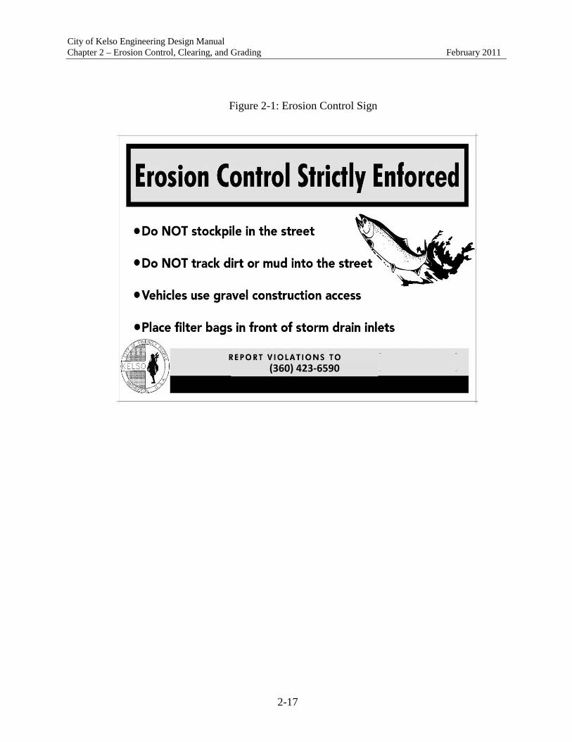
City of Kelso Engineering Design Manual Chapter 2 – Erosion Control, Clearing, and Grading February 2011
2-17
Figure 2-1: Erosion Control Sign
(360) 423-6590

City of Kelso Engineering Design Manual Chapter 2 – Erosion Control, Clearing, and Grading February 2011
2-18
2.11 Common Erosion and Sediment Control BMPs
A. Minimizing the area of land disturbance, retaining vegetation (including significant trees) and the native soil (including the duff layer), and phasing of construction will yield the greatest erosion control benefits.
B. Erosion and sediment controls must be installed before work begins, inspected
frequently (daily recommended), maintained or replaced as necessary, and upgraded or modified as conditions change.
C. Contractor workers should be trained in erosion control. D. Table 3.1: Common Erosion Control Strategies below summarizes common strategies
for erosion control for various types of projects and terrain.

City of Kelso Engineering Design Manual Chapter 2 – Erosion Control, Clearing, and Grading February 2011
2-19
Table 2.1: Common Erosion Control Strategies
* (Slope, Spacing on Contours): (<10%, 300’), (<15%, 150’), (<20%, 100’), (<30%, 50’), (≥30%, 25’) ** Wet weather seasonal restrictions apply from October 1st – April 30th.
Single Family /
Duplex Residential
Commercial, Subdivision, & Large
Site Construction
Ditch Swale Stockpiles
Base Measures / Slope <2% >2% <2% >2% >50% 1 Construction entrance X X X X X
2 Silt fence at toe of disturbed area or stockpile X X X X
3 Sidewalk/ subgrade barrier Alt to #2 Optional Optional 4 Filter strip (undisturbed buffer) Alt to #2 Alt to #2 Alt to #2
5 Fence, wattles, or mulch filter berm along contours * X X
6 Temp interceptor dike/swale around work areas Optional Optional Optional
7 Check dams X 8 Inlet protection X X X X X
9 Street sweeping (daily) X X X X X
Wet Weather Measures ** 10 Establish grass X X 11 Plastic sheeting Alt X X 12 2 inches of mulch cover Alt Alt Alt 13 Erosion blanket with anchors Alt Alt Alt 14 Sediment trap or pond Alt
Post Construction
15 Establish groundcover or landscaping prior to removing controls
X X X X

Chapter 3
Streets
City of Kelso Engineering Design Manual
February 2011

Chapter 3 Streets
City of Kelso Engineering Design Manual
February 2011
Table of Contents
Page Description No. 3.00 Functional Classification .........................................................................................................1 3.01 Access ......................................................................................................................................2 3.02 Intersections, Driveways and Approaches ...............................................................................4 3.03 Street Widths ..........................................................................................................................10 3.04 Surfacing Requirements .........................................................................................................16 3.05 Design Speed .........................................................................................................................17 3.06 Horizontal Alignment ............................................................................................................18 3.07 Vertical Alignment.................................................................................................................18 3.08 Transitions..............................................................................................................................19 3.09 Dedications and Guarantees ...................................................................................................20 3.10 Private Streets ........................................................................................................................21 3.11 Street Frontage Improvements ...............................................................................................25 3.12 Street Ends .............................................................................................................................28 3.13 Medians ..................................................................................................................................31 3.14 Sight Obstruction Requirements ............................................................................................31 3.15 Survey Monuments ................................................................................................................32 3.16 Sidewalks ...............................................................................................................................32 3.17 Multi-Use Trails .....................................................................................................................32 3.18 Bridges ...................................................................................................................................33 3.19 Landscaping in the Right-of-Way, Easements, and Access Tracts .......................................34 3.20 Street Illumination .................................................................................................................36 3.21 Traffic Control and Signing ...................................................................................................37 3.22 Appurtenances........................................................................................................................39 3.23 Franchise Utilities ..................................................................................................................39 3.24 Trench Backfill and Restoration ............................................................................................40 3.25 Speed Humps .........................................................................................................................40
Chapter 3 Streets
City of Kelso Engineering Design Manual
February 2011
Table of Contents
Page Description No. Figures Figure 3-1: Corner Lot Setback ....................................................................................................7 Figure 3-2: Major Arterial ..........................................................................................................11 Figure 3-3: Minor Arterial ..........................................................................................................11 Figure 3-3a: Industrial Minor Arterial ..........................................................................................12 Figure 3-4: Collector ...................................................................................................................12 Figure 3-4a: Industrial Collector ..................................................................................................13 Figure 3-4b: Industrial Collector w/Ditch ....................................................................................13 Figure 3-5: Local: Multi-family Area .........................................................................................14 Figure 3-6: Local: Single-family Area ........................................................................................14 Figure 3-6a: Local: Traffic Calming ............................................................................................15 Figure 3-6b: Roadway with Rain Gardens ...................................................................................15 Figure 3-7: Alleys: Commercial & Industrial .............................................................................15 Figure 3-8: Alleys: Residential ...................................................................................................16 Figure 3-9: Private Street Type I ................................................................................................23 Figure 3-10: Private Street Type II ...............................................................................................23 Figure 3-11: Private Street Type III ..............................................................................................24 Figure 3-12: Minimum Street Improvement .................................................................................27 Figure 3-13: Cul-De-Sac Dimensions...........................................................................................29 Figure 3-14: Temporary Cul-De-Sac ............................................................................................30 Figure 3-15: Trench Patch ............................................................................................................40 Tables Table 3.1 – Unsignalized Intersection Spacing ...............................................................................6 Table 3.2 – Minimum Distances from Corner Standards ...............................................................7 Table 3.3 – Curb Return Radii (Feet) Edge of Pavement/Curb-Minimums .................................10 Table 3.4 – Major Arterial Surfacing Requirements .....................................................................16 Table 3.5 – Minor Arterial Surfacing Requirements ....................................................................17 Table 3.6 – Collector Street Surfacing Requirements ...................................................................17 Table 3.7 – Local Street and Alley Access Surfacing Requirements ...........................................17 Table 3.8 – Vertical Alignments and Flood Plains .......................................................................19 Table 3.9 – Street Tree List ...........................................................................................................35

City of Kelso Engineering Design Manual Chapter 3 – Streets February 2011
3-1
CHAPTER 3 – STREETS 3.00 Functional Classification The functional classification of existing and proposed roads is established by the City on an individual basis using the existing land use and existing operational characteristics. The City Engineer will maintain a map that classifies each roadway. Kelso classifies roads and streets as follows:
A. Major Arterial
These facilities are the supporting elements of both the arterial routes and collector systems. Major arterials, in combination with minor arterial routes, are intended to provide a high level of mobility for travel within the region. All trips from one sub-area through an adjacent sub-area traveling to other points in the region should occur on a major arterial.
Access is generally limited to intersections with other arterials and collectors; direct residential access is not permitted. Direct land access is discouraged, kept to a minimum, and controlled. The level of fixed route transit service is high.
B. Minor Arterial
The minor arterial system complements and supports the major arterial system, but is primarily oriented toward travel within and between adjacent sub-areas. An adequate minor arterial system is needed to ensure that these movements do not occur on major arterials. These facilities provide connections to major activity centers and provide access from the major arterial systems into each sub-area.
They serve through traffic and provide direct access for commercial, industrial, office, and multi-family development, but generally, not for residential properties. Access to abutting lots is limited. Since minor arterials serve a more localized area, fixed route transit is moderate.
C. Collector
Collector streets connect local traffic within a subarea to arterial roads. Service to adjacent land uses is subordinate to traffic movement. Access to abutting properties and parking is controlled through the use of raised channelization, driveway spacing, bicycle and/or pedestrian lanes, and pavement markings. Typically, collector streets are not continuous for any great length, nor do they form a connected network by themselves. Since collector streets connect arterial networks and also connect neighborhoods to

City of Kelso Engineering Design Manual Chapter 3 – Streets February 2011
3-2
commercial areas as well as each other, fixed route transit service is low. Access to abutting lots is limited.
D. Local: Multi-family Areas
Local: Multi-family streets serve to distribute traffic from collectors and provide direct access for abutting properties. Through trips are discouraged and parking is allowed.
E. Local: Single-family Areas
Local: Single-family streets provide access to adjoining properties within a neighborhood. Through trips are discouraged and parking is allowed. Services a very limited number of houses.
F. Alleys (Commercial & Industrial, Residential)
Alleys provide service access to adjoining properties through one-way traffic. Through trips and parking are not allowed. No fixed route transit usage and the focus is for service and localized access. Services a very limited number of lots.
3.01 Access The City Engineer shall have the authority to limit access and designate access locations on public streets under the jurisdiction of the City. When a parcel has multiple roadway frontages, access shall be granted from the lesser classification roadway. Access to streets and highways under Cowlitz County or State of Washington jurisdiction must be formally approved by those entities at the applicant's initiative and expense.
A. Request Process 1. Applications. Applicants may request a street access connection permit as part of
an underlying Development application, or they may file separately for a street access connection permit if the connection is being requested without relation to an underlying land use application.
2. Approval. The issuance or denial of the street access connection permit shall be
made administratively by the City Engineer.
3. Submittal Requirements for Street Access. Per section 1.04K of these standards.\
4. Permit Issuance. In order to receive a street access connection permit the applicant must comply with the following:

City of Kelso Engineering Design Manual Chapter 3 – Streets February 2011
3-3
a. The design standards for the functional classification of the roadway that the proposed connection will access.
b. If the proposed connection is an expansion or change of use of a pre-existing
non-conforming access, the applicant must demonstrate that the proposed connection will not substantially adversely affect the safety of the roadway section that the proposed connection will access through an interim access permit application.
c. Pursuant to the Washington State Environmental Policy Act (SEPA), the City
shall have the authority to impose conditions upon the permit to mitigate the specific adverse impacts created by the connection.
5. Variance from Access Standards. The Access Standards may be modified by the
City Engineer on the street access connection permit upon a showing by the applicant of the following:
a. Topography, right-of-way, existing construction or physical conditions, or other
geographic conditions impose an unusual hardship on the applicant, and an equivalent alternative which can accomplish the same access management purpose is available.
b. A minor change to a standard is required to address a specific design or
construction problem, which if not enacted, will result in an unusual hardship. c. An alternative standard is proposed which is equal to or superior to these
standards. d. Application of the standards of this chapter to the development would be grossly
disproportional to the impacts created. 6. Interim Access. When and if a property/parcel can not meet current access spacing
standards, an interim access permit may be pursued. The purpose of the interim access permit is to allow access (that does not meet approved access spacing standards) to a property until such time when acceptable access spacing standards can be met. An interim access permit shall be granted upon meeting the following criteria:
a. Access to the property/parcel can not meet current access spacing criteria; b. The interim access shall be evaluated for traffic operations (including queuing)
and safety criteria and shall meet minimum transportation operating conditions

City of Kelso Engineering Design Manual Chapter 3 – Streets February 2011
3-4
and not create an adverse safety situation (dependant upon review from the City Traffic Engineer).
c. The property owner agrees to sign a waiver of the right to demonstrate against
the formation of a local improvements district, or similar financing mechanism, for the primary purpose of providing roadway infrastructure to help create a network that would allow for adequate access to the parcel that meets current access spacing standards. Once that infrastructure is in place the interim access would be closed.
d. The property owner records an agreement with the City, County and/or WSDOT
to participate in efforts to achieve adequate access that meets access spacing standards to help eliminate the interim access.
e. The property owner agrees to vacate (and close) the interim access when an
appropriate alternative access is identified and constructed which meets the current access spacing criteria.
7. Suspension. The City Engineer shall have the right to suspend a street access
connection permit where the applicant fails to comply with the conditions and access standards of the street access connection permit. The street access connection permit can be reinstated upon compliance with conditions and access standards of the street access connection permit. If after 180 days the applicant has failed to comply with conditions, the City Engineer has the right to revoke the street access connection permit.
3.02 Intersections, Driveways, and Approaches
A. General Requirements
1. Standard residential, commercial, or industrial driveway approaches shall be required for all driveways accessing onto a public (or private) right-of-way or easement.
2. A private intersection opening may be used in lieu of a conventional driveway
approach in commercial and industrial areas where all of the following criteria are met:
a. Projected driveway usage is greater than two-thousand (2,000) vehicles per day. b. In any case where traffic signalization is approved, warranted, and provided. c. A minimum one-hundred (100) foot storage area is provided between the street

City of Kelso Engineering Design Manual Chapter 3 – Streets February 2011
3-5
and any turning or parking maneuvers within the development. d. The opening is at least one-hundred and fifty (150) feet from any other
intersection opening, including driveways on or off the property frontage and under control of the applicant or not.
e. Easement dedication for traffic control devices is provided.
B. Conditions of Approval
1. Driveways directly giving access onto arterials shall be denied if alternate access is
available. 2. All abandoned driveway areas on the street frontage to be improved shall be
removed and new curb, gutter, and sidewalk shall be installed. 3. No commercial or industrial driveway shall be approved where backing onto the
sidewalk or street will occur. 4. No driveway shall be approved where backing onto a street might occur if the slope
of the driveway is greater than ten percent (10%) within the first twenty (20) feet of the property line.
5. Left turns from and to a driveway may be restricted as a development condition or
in the future if such maneuvers are found to be unduly hazardous. 6. Driveways approaches shall be aligned wherever practicable with existing
driveways on the opposite side of the street. 7. All driveways shall be angled ninety-degrees (90°) to the street, unless otherwise
approved by the City Engineer.
C. Intersection/Driveway Spacing. Intersections are divided into two categories for determining spacing requirements: signalized access spacing and unsignalized access spacing, which include both driveways and intersections.
1. Number of Driveways Approaches per Property. Property owners shall be granted
one access per property. Design modification requests for additional driveways must be supported by a traffic impact study. Any additional access should conform to these standards. If the property has frontage along two or more streets, access shall be from the lower classification street unless approved through the design modification process. Final approval of access (per property) shall be through the City Engineer.

City of Kelso Engineering Design Manual Chapter 3 – Streets February 2011
3-6
2. Signal Spacing. Signalized access on all roadways shall be no less than 1,250 feet
for full access, and should maintain adequate signal progression. 3. Measurement of Access Spacing. Spacing of signalized and unsignalized roadway
intersections, as well as driveways, are described in Table 3.1 and shall be measured from the centerline of the intersections being measured. Distances from intersection corners for access driveways as described in Table 3.2 shall be measured between the nearest edges of the driveways, edge of roadway or curb line. Where the distance required from the corner is greater than the parcel frontage, the driveway approach shall be placed at the farthermost distance from the adjacent driveway.
Table 3.1
Unsignalized Intersection Spacing
Roadway Classification
Minimum Full Access Spacing (ft)
Maximum Full Access Spacing (ft)
Right-in/Right-out Access Spacing
(ft)
Major Arterial 1,250 2,000 400
Minor Arterial 600 1,000 300
Collector 400 800 200
Local Multi-Family 100 500 n/a
Local Single-Family 25 500 n/a
In the case of long or oddly shaped blocks and to facilitate pedestrian access to parks, playgrounds, open space or schools, the applicant shall construct pedestrian paths of not less than ten feet in width on a dedicated right-of-way or perpetually unobstructed easement of not less than twenty feet in width, to extend through the block(s) at location(s) deemed necessary by the City Engineer.
D. Access from Alleys. There shall be no access from alleys except where the intersecting
and parallel streets are classified as Local Access Residential. On Local Access Residential streets, one alley access shall be permitted whose width shall conform to the standard widths for a driveway if the alley access is the only access for the residence.
E. Corner Standards. Driveways approaches on corner parcels shall be placed on the
roadway with the lower classification. If both roadways have the same classification, the City Engineer shall determine on which roadway the driveway shall be located. It

City of Kelso Engineering Design Manual Chapter 3 – Streets February 2011
3-7
may be necessary to perform a queuing analysis to determine if the queue on the roadway where access is being requested blocks the proposed access.
Table 3.2
Minimum Distances from Corner Standards
Functional Classification Minimum Access
Set-back from Corner (ft)
Major Arterial 300
Minor Arterial 200
Collector 100
Local 50
The corner point from which to measure is the curb return radius and is shown in Figure 3-1. Where the distance required from the corner is greater than the parcel frontage, the driveway shall be placed at the furthermost distance from the intersection.
Figure 3-1: Corner Lot Setback

City of Kelso Engineering Design Manual Chapter 3 – Streets February 2011
3-8
F. Restrictive Median Curbs. Except for Local Access and Local Access Residential roadways, restrictive median curbs shall be used to restrict turning and crossing movements as follows:
1. If access spacing outlined in Tables 3.1 and 3.2 cannot be met, median barrier curbs
shall be installed of sufficient length to restrict left turn and crossing movements, or between full access intersections, whichever is greater.
2. At signalized intersections on principal arterials, the length of restrictive median
curbs shall be equal to the driveway spacing distance determined by Table 3.2, regardless whether or not driveways exist.
3. At intersections with left turn lanes on principal arterials, minor arterials, and
neighborhood collectors, the length of restrictive median curbs shall be equal to the left turn lane storage length, except as may be required by condition number 2 above.
4. The respective City Engineer shall determine restrictive median curb types and
placements.
G. Turn Lane Warrants
1. Turn lanes (left and right) may be warranted at unsignalized intersections, and should be evaluated using appropriate left or right turn lane warrants utilizing standards adopted by the City or State depending on which facility is being analyzed.
2. At signalized intersections, a traffic impact study should be used to determine
required storage length for left or right turn lanes.
H. Driveway Design Criteria:
1. Width. Two-way multi-family residential driveways shall have a minimum width of sixteen (16) feet and a maximum width of twenty-two (22) feet. Two–way commercial driveways shall have a minimum width of twenty-four (24) and a maximum width of thirty (30) feet. Where intersection openings are approved the width shall be as determined by the City Engineer.
One-way multi-family residential driveways shall have a minimum width of ten (10) feet and a maximum width of twelve (12) feet. One-way commercial driveways shall have a minimum driveway width of twelve (12) feet with a maximum width of sixteen (16) feet. Commercial driveways shall meet the separation requirements of Section 3.02. Parking lot circulation needs shall be met

City of Kelso Engineering Design Manual Chapter 3 – Streets February 2011
3-9
on site. The public right-of-way shall not be utilized as part of a one-way parking lot flow. A single family driveway shall have a minimum width of ten (10) feet and maximum width of sixteen (16) feet. A wider commercial or industrial driveway width may be approved by the City Engineer where a substantial percentage of oversized vehicle traffic is anticipated and a written request and turning diagrams are submitted. The request shall include justification for the oversized vehicles and the design vehicle selection as well as detailed alternatives and considerations that were evaluated.
2. Clearance from structures. No object (including fire hydrants, light or power poles,
street trees) shall be placed or allowed to remain within six (6) feet of the driveway wing and edge.
Where the building facade or other design element is less than ten (10) feet behind the sidewalk, both pedestrian and vehicular sight distance shall be maintained.
3. Sight Distance. Sight distance shall be designed per AASHTO guidelines. 4. A landing shall be provided in accordance with section 3.07.
The following specifies the minimum requirements for intersections: I. Angle between intersections.
The interior angle at intersecting streets shall be kept as near to ninety degrees (90º) as possible and in no case shall it be less than seventy-five degrees (75º), nor more than fifteen degrees (15º), from the ninety (90º). A tangent section shall be carried a minimum of fifty (50) feet each side of intersecting right-of-way lines. When possible, intersections shall align with any existing intersection on the opposite side of the street.
J. Curb returns:
Minimum curb radii at intersections shall be shown in Table 3.3 for the various functional classifications. The right-of-way radii at intersections shall be sufficient to maintain at least the same right-of-way to curb spacing as the upper classified street.
Sidewalk access ramps shall be provided at all corners of all intersections, regardless of curb type.

City of Kelso Engineering Design Manual Chapter 3 – Streets February 2011
3-10
Table 3.3 Curb Return Radii (Feet)
Edge of Pavement/Curb –Minimums
Street Classification
Major/Minor Arterial Street
Collector Street
Local Streets
Major/Minor Arterial Street
25
25
25
Collector Street 25
20
20
Local Streets
25
20
15
K. It is the policy of the City to have the applicant’s engineer evaluate safe intersection
sight distance using the principles and methods recommended by AASHTO. L. Traffic control will be as specified in the Manual of Uniform Traffic Control Devices
(M.U.T.C.D.) or as modified by the Engineer as a result of appropriate traffic engineering studies.
M. Traffic signal modification, relocation, or installation is required when roadway or
driveway geometrics interfere with existing signal facilities, or would result in an un-signalized approach, or intersection that meets signal warrants.
3.03 Street Widths
The figures below show the road width standards by the functional classification of the road. Authority to determine a street's class shall lie with the city engineer. It should be noted that public utility easements beyond the right-of-way are typically required. Lane configuration shall be compared to existing conditions and determined at the time of construction drawing approval. Additional right-of-way and pavement width may be required, in addition to that shown in Figures 1 thru 8, to allow parking, turn lanes and median strips. Additional right-of-way or easements may be required for cut or fill embankments.

City of Kelso Engineering Design Manual Chapter 3 – Streets February 2011
3-11
Figure 3-2: Major Arterial Design Speed: 35 mph
*6’ PUE unless otherwise approved *66’ paved width to accommodate a 12’ center turn lane/median if determined necessary by the City Engineer
Figure 3-3: Minor Arterial Design Speed: 35 mph
*6’ PUE unless otherwise approved

City of Kelso Engineering Design Manual Chapter 3 – Streets February 2011
3-12
Figure 3-3a: Industrial Minor Arterial Design Speed: 35 mph
Figure 3-4: Collector
Design Speed: 25 mph
*6’ PUE unless otherwise approved

City of Kelso Engineering Design Manual Chapter 3 – Streets February 2011
3-13
Figure 3-4a: Industrial Collector Design Speed: 35 mph
Figure 3-4b: Industrial Collector w/ Ditch Design Speed: 35 mph

City of Kelso Engineering Design Manual Chapter 3 – Streets February 2011
3-14
Figure 3-5: Local: Multi-family Area Design Speed: 25 mph
*6’ PUE unless otherwise approved
Figure 3-6: Local: Single –family Areas Design Speed: 25 mph
*6’ PUE unless otherwise approved

City of Kelso Engineering Design Manual Chapter 3 – Streets February 2011
3-15
Figure 3-6a: Local: Traffic Calming Design Speed: 25 mph
Figure 3-6b: Roadway with RainGardens
Figure 3-7: Alleys: Commercial & Industrial Design Speed: 25 mph

City of Kelso Engineering Design Manual Chapter 3 – Streets February 2011
3-16
Figure 3-8: Alleys: Residential Design Speed: 25 mph
3.04 Surfacing Requirements
The pavement structure thickness identified for these soil and roadway types is required unless a site-specific pavement design is done. The total pavement structure shall not exceed two and one half (2.5) feet. Asphalt concrete pavement shall be HMA Class A, PG 64-22 per the Standard Specifications. Subgrade reinforcement geotextiles shall be installed prior to constructing the base and surfacing.
Table 3.4 Major Arterial
Surfacing Requirements
AASHTO Soil Type
Hot Mix Asphalt Thickness
Base Rock Thickness
A-1 – A-3 0.55’ 0.55’ A-4 – A-7 0.60’ 1.35’ Other No Section Estimated

City of Kelso Engineering Design Manual Chapter 3 – Streets February 2011
3-17
Table 3.5 Minor Arterial
Surfacing Requirements
AASHTO Soil Type
Hot Mix Asphalt Thickness
Base Rock Thickness
A-1 – A-3 0.50’ 0.50’ A-4 – A-7 0.50’ 1.45’ Other No Section Estimated
Table 3.6 Collector Street
Surfacing Requirements
AASHTO Soil Type
Hot Mix Asphalt Thickness
Base Rock Thickness
A-1 – A-3 0.45’ 0.45’ A-4 – A-7 0.45’ 1.15’ Other No Section Estimated
Table 3.7
Local Street and Alley Access, Surfacing Requirements
AASHTO Soil Type
Hot Mix Asphalt Thickness
Base Rock Thickness
A-1 – A-3 0.35’ 0.50’ A-4 – A-7 0.35’ 0.90’ Other No Section Estimated
3.05 Design Speed
The minimum design speed for each road classification shall be as shown in Figures 3-2 thru 3-8 or as otherwise approved by the City Engineer.

City of Kelso Engineering Design Manual Chapter 3 – Streets February 2011
3-18
3.06 Horizontal Alignment A. General Design
1. Horizontal alignment shall be designed per AASHTO guidelines. 2. Super elevations may only be used with the written approval of the City Engineer.
Where super elevation is used, street curves should be designed per AASHTO guidelines, except that the maximum super elevation rate of 0.04 shall be used.
3. Off-set crown cross-sections are not acceptable as super elevation sections. 4. Streets shall be related appropriately to the topography and shall follow the more
gradual natural contours of the land.
B. Residential Design
1. Streets shall be aligned to provide for continuation of streets in adjoining subdivisions and to allow for future opening of streets to possible adjoining subdivisions.
2. Streets shall be oriented within twenty-five degrees of east-west to the maximum
extent possible to enhance solar access to residences. If other considerations such as topography and contours or connection with existing principal streets adversely affect this standard then alternatives may be considered. This may include assurance that the majority of lots have their axes oriented north-south regardless of the angle of incidence of lot lines with street lines.
3. Direct driveway access to major arterials shall be prohibited, and direct driveway
access to minor arterials and collectors shall be minimized. A buffer strip may be used and a separated service or marginal access road may be utilized.
3.07 Vertical Alignment
Street alignments shall meet the following requirements:
• Minimum tangent street gradients shall be one-half percent (0.5%) along the crown and curb;
• Maximum street gradients shall not exceed fifteen percent (15%) for residential streets, ten percent (10%) for collector streets, and seven percent (7%) for arterials;
• Minimum street gradients shall be at least one-half percent (0.5%) along the gutter; • Long sweeps of more than ten percent (10%) shall be avoided. • Local streets intersecting with a collector or greater functional classification street or
streets intended to be posted with a stop sign shall provide a landing averaging five
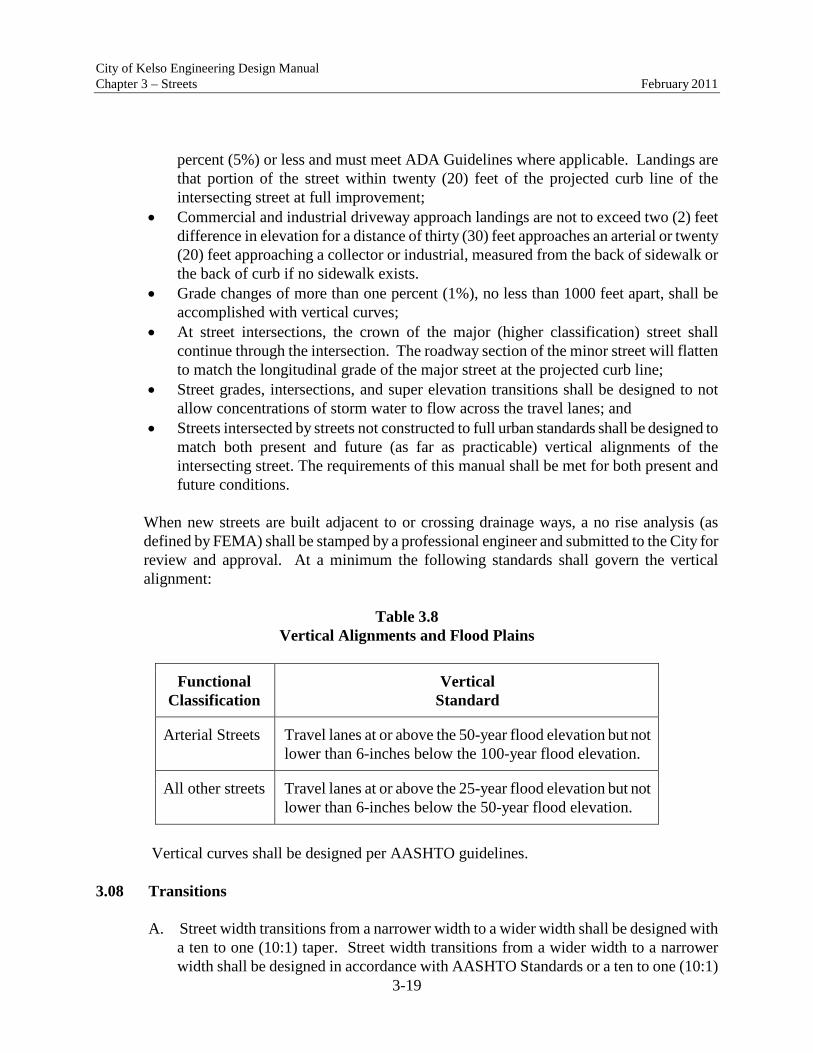
City of Kelso Engineering Design Manual Chapter 3 – Streets February 2011
3-19
percent (5%) or less and must meet ADA Guidelines where applicable. Landings are that portion of the street within twenty (20) feet of the projected curb line of the intersecting street at full improvement;
• Commercial and industrial driveway approach landings are not to exceed two (2) feet difference in elevation for a distance of thirty (30) feet approaches an arterial or twenty (20) feet approaching a collector or industrial, measured from the back of sidewalk or the back of curb if no sidewalk exists.
• Grade changes of more than one percent (1%), no less than 1000 feet apart, shall be accomplished with vertical curves;
• At street intersections, the crown of the major (higher classification) street shall continue through the intersection. The roadway section of the minor street will flatten to match the longitudinal grade of the major street at the projected curb line;
• Street grades, intersections, and super elevation transitions shall be designed to not allow concentrations of storm water to flow across the travel lanes; and
• Streets intersected by streets not constructed to full urban standards shall be designed to match both present and future (as far as practicable) vertical alignments of the intersecting street. The requirements of this manual shall be met for both present and future conditions.
When new streets are built adjacent to or crossing drainage ways, a no rise analysis (as defined by FEMA) shall be stamped by a professional engineer and submitted to the City for review and approval. At a minimum the following standards shall govern the vertical alignment:
Table 3.8
Vertical Alignments and Flood Plains
Functional Classification
Vertical Standard
Arterial Streets Travel lanes at or above the 50-year flood elevation but not lower than 6-inches below the 100-year flood elevation.
All other streets Travel lanes at or above the 25-year flood elevation but not lower than 6-inches below the 50-year flood elevation.
Vertical curves shall be designed per AASHTO guidelines.
3.08 Transitions
A. Street width transitions from a narrower width to a wider width shall be designed with a ten to one (10:1) taper. Street width transitions from a wider width to a narrower width shall be designed in accordance with AASHTO Standards or a ten to one (10:1)

City of Kelso Engineering Design Manual Chapter 3 – Streets February 2011
3-20
taper whichever is greater. Delineators, as defined by the MUTCD and approved by the City, shall be installed to define the configuration.
In situations where a tapered transition cannot be provided, a type III barricade shall be
installed at the end of the wider section of the street and a taper shall be appointed and delineated as approved by the City Engineer.
B. Lane transitions shall be designed per AASHTO guidelines.
3.09 Dedications and Guarantees
A. Right-of-way shall be deeded for streets and other improvements as required per Figures 3-2 thru 3-8 to accommodate motorized and non-motorized transportation, landscaping, utility, and buffer requirements.
B. Public utility tracts and/or easements for all public systems shall be provided as required. Specific requirements for sewer, water, and storm drainage easements are detailed in the relevant chapters. Particular design features of a road may necessitate slope, wall, or drainage easements. Such easements may be required by the City Engineer in conjunction with dedication or acquisition of rights-of-way and other standard easements (temporary construction, right-of-entry, sidewalk, pedestrian, street lighting, and traffic control devices, etc.)
C. Special Access Easements or Tracts.
Where it is necessary to facilitate pedestrian circulation between neighborhoods, schools, shopping, or other activity centers, public access easements or tracts shall be dedicated. Improvements to the easement shall include a sidewalk or trail consistent with other non-motorized facilities in the area. Fences shall be constructed along access easements in residential areas where buildings will be located nearer than fifty (50) feet to the edge of the easement. Traffic diverters or bollards shall be installed at the direction of the City Engineer. Pedestrian access easements or tracts shall be a minimum of fifteen (15) feet wide. If the easement is over one-hundred and fifty (150) feet in length, the width shall be twenty (20) feet. Structure setbacks shall be a minimum of five (5) feet from the edge of the easement or tract.
D. All subdivisions and short subdivisions (short plats) will be required to deed additional
right-of-way, as a condition of approval of the subdivision, where the existing right-of-way for a public street is not adequate to incorporate necessary frontage

City of Kelso Engineering Design Manual Chapter 3 – Streets February 2011
3-21
improvements for public safety and provide compatibility with the area's circulation system.
All short subdivisions (short plats) will be required to deed additional right-of-way, as a condition of approval of the short plat, under one or more of the following conditions:
1. The short plat abuts an existing substandard public street and the additional
right-of-way is necessary to incorporate future frontage improvements necessary for public safety, or
2. Additional right-of-way is needed to provide right-of-way for the extension of
existing public street improvements necessary for public safety, or 3. Additional right-of-way is needed to provide future street improvements necessary
for public safety for planned new public streets. E. All recording costs for easements created by private development shall be borne by the
Applicant. F. Prior to commencing construction of any component of the public street or sidewalk, the
Applicant shall submit to the City an approved performance bond in accordance with the requirements of Section 1.08 of these Standards.
3.10 Private Streets
A. Criteria for Authorization. It is the City of Kelso's policy to discourage private streets and to only permit them under unusual circumstances. Private streets may be permitted only if they meet all the following conditions:
1. A road modification for the street has been approved by the City Engineer, 2. Covenants have been approved, recorded, and verified with the City which provide
for maintenance of the private streets and associated parking areas by owners in the development. Covenant shall include a periodic maintenance schedule, be enforceable by any property owner served by that road, include a formula for assessing maintenance and repair costs, shall run with the land;
3. Provisions are made for the streets to be open at all times for emergency and public
service vehicles; 4. The private streets will not obstruct public street circulation, and

City of Kelso Engineering Design Manual Chapter 3 – Streets February 2011
3-22
5. The following conditions exist: a. The plat or short plat street will ultimately serve no more than fifty (50) single
family lots or the roadways serve commercial or industrial facilities where no circulation continuity is necessary; and
b. The City Engineer determines that no other access is available and the private road is adequate for the area it is to service,
c. The private road shall not connect two public roads, d. No public utilities shall be located within the private street without approval
from the City Engineer.
B. Notice. A statement is required on the face of any plat or short plat and in the CCRs containing a private road with the following: "The City of Kelso has no responsibility to improve or maintain the private roads contained within, or private roads providing access to the property described in this plat."
C. Easements. Private streets shall be constructed within easements with an easement
width of sixty (60) feet. If the applicant does not own the property in which the easement crosses a modification may be applied for in accordance with Chapter 12 of the KMC. Easements shall be expanded in width as may be necessary to include all cuts, fill, turnouts and turnarounds as required.
D. Turnarounds. Turnarounds shall be provided at the end of all private streets longer than
one-hundred and fifty (150) feet and at one-thousand feet intervals along the length of a private street where no intersecting roadway exists. Turnarounds shall have a minimum radius of forty (40) feet and all interior corners shall have a minimum radius of twenty-five (25) feet.
E. Grading. All filling and grading associated with the construction of a private road shall be conducted in accordance with current WSDOT Standard Specifications for Roads and Bridges. A geotechnical report, prepared by a qualified expert shall be provided for any grading which will incorporate cutting or filling in excess of five (5) feet, cut slopes in excess of one vertical to two horizontal (2:1), or fill slopes in excess of one vertical to two horizontal (2:1). Such report shall identify materials to be used, compaction rates and methods, maximum allowable slopes, and erosion control methods.
E. Construction Requirements. Private streets shall conform to public street construction
standards with the following exceptions:

City of Kelso Engineering Design Manual Chapter 3 – Streets February 2011
3-23
Figure 3-9: Private Street Type I 20-50 Residential Units
Figure 3-10: Private Street Type II
10-19 Residential Units
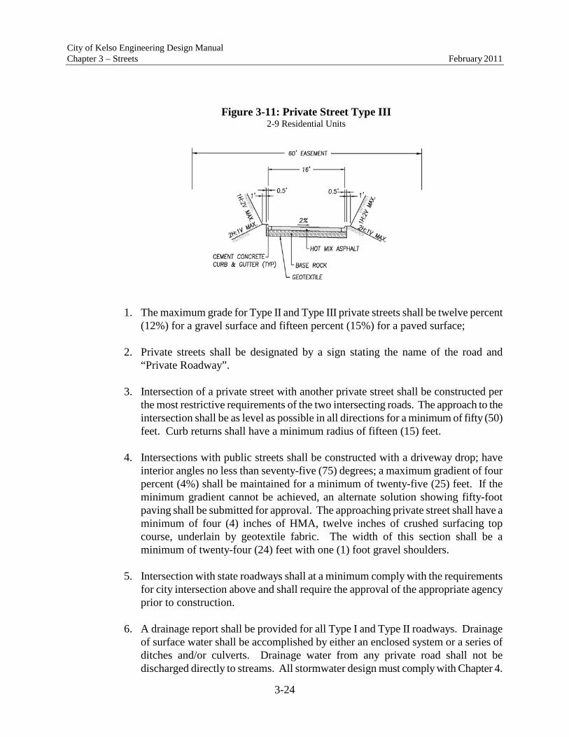
City of Kelso Engineering Design Manual Chapter 3 – Streets February 2011
3-24
Figure 3-11: Private Street Type III 2-9 Residential Units
1. The maximum grade for Type II and Type III private streets shall be twelve percent (12%) for a gravel surface and fifteen percent (15%) for a paved surface;
2. Private streets shall be designated by a sign stating the name of the road and
“Private Roadway”. 3. Intersection of a private street with another private street shall be constructed per
the most restrictive requirements of the two intersecting roads. The approach to the intersection shall be as level as possible in all directions for a minimum of fifty (50) feet. Curb returns shall have a minimum radius of fifteen (15) feet.
4. Intersections with public streets shall be constructed with a driveway drop; have
interior angles no less than seventy-five (75) degrees; a maximum gradient of four percent (4%) shall be maintained for a minimum of twenty-five (25) feet. If the minimum gradient cannot be achieved, an alternate solution showing fifty-foot paving shall be submitted for approval. The approaching private street shall have a minimum of four (4) inches of HMA, twelve inches of crushed surfacing top course, underlain by geotextile fabric. The width of this section shall be a minimum of twenty-four (24) feet with one (1) foot gravel shoulders.
5. Intersection with state roadways shall at a minimum comply with the requirements
for city intersection above and shall require the approval of the appropriate agency prior to construction.
6. A drainage report shall be provided for all Type I and Type II roadways. Drainage
of surface water shall be accomplished by either an enclosed system or a series of ditches and/or culverts. Drainage water from any private road shall not be discharged directly to streams. All stormwater design must comply with Chapter 4.

City of Kelso Engineering Design Manual Chapter 3 – Streets February 2011
3-25
7. All work must be completed in accordance with the erosion control standards as set forth in Chapter 2.
8. Any bridge on a Type II roadway shall be constructed to the AASHTO and/or state
standards, whichever is more restrictive. Any bridge on a Type III shall be built to a bridge design standard as specified in the International Building Code using live loading and/or state, standards whichever is more restrictive.
F. Acceptance as Public Streets. Acceptance of private streets as public streets will be
considered only if the street meets all applicable public street standards contained herein.
G. Maintenance. The city will not maintain roadways, signs or drainage improvements on
private roads. A private maintenance covenant recorded with the county auditor will be required for any private road. The covenant shall set out the distribution of expenses, remedies for noncompliance with the terms of the agreement, right of use easements and other considerations. The covenant shall include the following terms:
1. The covenant shall establish minimum annual assessments in an amount adequate
to defray costs of ordinary maintenance and procedures for approval of additional needed assessments.
2. The covenant shall include a periodic maintenance schedule. 3. The covenant for maintenance shall be enforceable by any property owner served by
that road. 4. The covenant shall establish a formula for assessing maintenance and repair costs
equitably to property owners served by the private road. 5. The covenant shall run with the land. 6. Maintenance shall include, but not be limited to, road surfacing, shoulders, signs,
storm drainage facilities and vegetation control.
The requirements of maintenance agreements on existing private roads will be determined on legal viability.
3.11 Street Frontage Improvements
A. All developments shall install street frontage improvements at the time of construction as detailed in their approval, or as directed by the City Engineer. Such improvements shall include, but not be limited to, curb and gutter; sidewalk; storm drainage; street

City of Kelso Engineering Design Manual Chapter 3 – Streets February 2011
3-26
lighting system; utility undergrounding (relocation may be required); and street and/or right-of-way widening per these Standards. Traffic signal modification, relocation or installation; landscaping and irrigation may also be required. The frontage street shall be reconstructed from the center line of the proposed street width.
B. Corner parcels shall provide full half street frontage improvements on arterials
roadways and be evaluated according to 3.10C for each non-arterial fronting street C. Frontage improvements shall include a two (2) inch inlay of the half width if
construction invades the opposite side of the street. D. Subdivisions under 4 lots and site plans under five thousand (5,000) square feet shall be
required to provide full half-street frontage improvements along arterial roadways and shall at a minimum be required to match the predominant characteristic/condition of the existing non-arterial fronting roadway, where the majority of the parcels are developed.
The predominant existing or potential condition shall be defined by considering the
existing frontage conditions for all parcels fronting the half-street without development or redevelopment potential; if less than fifty percent (50%) have frontage improvements or partial improvements only, the subject development shall meet that standard. Where fifty percent (50%) or more have full improvements, or the potential for development or redevelopment, half-street frontage improvements shall be required.
In situations where the City Engineer finds that other pending or approved
unconstructed developments on the same street frontage would cause the calculation in 3.10C to exceed fifty percent (50%) or where other recorded covenants requiring frontage improvements exist, or where it is determined that deferral will cause an adverse impact or create dangerous or hazardous conditions, the City Engineer may require half-street frontage improvements.
In situations where the applicant is required to match the existing
characteristic/condition of the existing non-arterial, the minimum frontage shall resemble the following:

City of Kelso Engineering Design Manual Chapter 3 – Streets February 2011
3-27
Figure 3-12: Minimum Street Improvement
E. To allow for reasonable development, half-street improvements may be approved by the
City Engineer. Whenever a half-street improvement is approved, it shall conform to the following:
1. Street section design and construction shall be in conformance with these standards. 2. Minimum pavement width shall be 24 feet for arterial, collector and industrial
streets, and 20 feet for residential streets. 3. Intersectional improvements shall be adequate to provide turn lanes.
a. Arterials, collectors and industrials: 40 feet paved width, or the required width for the street (whichever is less), for 250 feet as measured from centerline of the intersecting street
b. Residential: 36 feet paved width, or the required width for the street (whichever is less), for 150 feet as measured from centerline of the intersecting street.
F. The following minimum standards shall apply to the development of single family
residential dwelling units on an unimproved right of way (existing plats), and private roads:
1. The existing right-of-way width, HMA width, and sidewalk status shall be extended
to match the nearest paved street. Minimum surfacing of all local private access streets shall be 3” of compacted HMA over 3” of compacted 5/8”-0” crushed top course, 4” of compacted 1-1/4”-0” crushed base rock. Compacted depths shall meet

City of Kelso Engineering Design Manual Chapter 3 – Streets February 2011
3-28
or exceed existing subgrade depth. 2. An improved turn-around shall be provided in accordance with section 3.12 of these
standards if the lot to be developed is located at the end of any road that is over 150 feet in length.
3. All utilities which have not already been installed to serve the site shall be
constructed to full City standards as set forth in these standards. The list of affected utilities shall include but not be limited to water, sanitary sewer, storm drainage, electrical and communications.
4. The grades shall be established by the applicant’s engineer. The HMA matching
width shall be a minimum of twenty (20) feet and must meet these standards. 5. If the applicant does not or can not bear the cost of connectivity and if the
latecomers agreement does not apply, Council will form an LID if improvements are required as a health and safety issue. Otherwise development will not be allowed.
6. The intent of the exception for a singular lot development is to allow a private party
to build and access a single family residence without the financial burden of completely developing the facilities to all the lots. Should the private party acquire an interest in the intermediate lots, he will be considered as a developer and the above exception shall not be allowed.
3.12 Street Ends
A. Cul-de-sacs: Cul-de-sacs shall be provided at all public and private street ends on all streets that are longer than one-hundred fifty (150) feet and up to four-hundred (400) feet in length, measured from the centerline of the intersecting road to the center of the cul-de-sac. The cul-de-sac may include a planting circle in the center.
1. No dead end street shall be allowed that obstructs public street circulation. 2. All street ends shall be paved and signed “No Parking.” 3. All requirements for utility/landscape strips and sidewalk for the adjacent street
section shall apply. 4. The minimum curb radius for transitions into cul-de-sac bulbs shall be twenty-five
(25) feet, and the right-of-way radius shall be sufficient to maintain the same

City of Kelso Engineering Design Manual Chapter 3 – Streets February 2011
3-29
right-of-way to curb spacing as in the adjacent portion of the road. The minimum distance from center of a cul-de-sac to the subdivision boundary is one-hundred fifty (150) feet.
Figure 3-13: Cul-De-Sac Dimensions
X. 40’ for residential areas 60’ for commercial and industrial areas Y. 50’ for local streets and minor arterials 75’ for commercial and industrial areas
B. Hammerheads:
Hammerheads may be used on private streets in lieu of a cul-de-sac. The hammerhead shall be signed “No Parking.” A driveway shall not be used as part of the hammerhead.
C. Temporary Dead Ends:

City of Kelso Engineering Design Manual Chapter 3 – Streets February 2011
3-30
Where a street is temporarily dead ended, turn around provisions must be provided where the road serves more than one (1) lot or is greater than one-hundred fifty (150) feet in length. 1. A cul-de-sac with a minimum radius forty (40) feet for residential areas and sixty
(60) feet for commercial industrial areas shall be provided.
Figure 3-14: Temporary Cul-De-Sac
2. All temporary dead ends shall have a Type III barricade with signage denoting a
future street extension and “No Parking.” 3. All temporary dead ends shall be removed by the Applicant responsible for
extending the road. D. Cul-de-sacs, eyebrows, and turnaround areas shall be allowed only on local streets and
commercial/industrial streets. E. An eyebrow corner may be used on a local street where expected ADT will not exceed
five-hundred (500) vehicles per day or as otherwise approved by the City Engineer. Minimum curb radius on the outside of an eyebrow corner is forty-one (41) feet; minimum right-of-way radius is forty-nine (49) feet. Eyebrow geometry shall be evaluated on the basis of turning requirements for Fire Department vehicles.
F. The final plat shall contain a notation that the easement outside of normal right-of-way

City of Kelso Engineering Design Manual Chapter 3 – Streets February 2011
3-31
shall be void at such time the street is continued and the paved turning radius is removed.
3.13 Medians
A median shall be in addition to, not part of, the specified road width. Where raised medians are allowed, the following criteria must be met:
A. Landscaping and irrigation shall be required. Plans shall be prepared by a qualified
Landscape Architect. B. Shall be designed so as not to limit turning radius or sight distance at intersections.
1. The raised median shall be set back at least two (2) feet from the median lane on
both sides. 2. Street lighting shall be sufficient to provide illumination of the raised median. 3. Objects, such as trees, shrubs, signs, and light poles shall not physically or visually
interfere with vehicle or pedestrian traffic in the travel way. 4. The style and design of the raised median shall be site specific. The raised median
shall be safe for the design speed, and shall be subject to approval by the City Engineer.
C. Shall be maintained by the homeowners association unless otherwise approved.
3.14 Sight Obstruction Requirements
A. Sight distance should be maintained at all driveways, buildings, or garage entrances where structures, wing walls, etc. are located adjacent to, or in close proximity to, a pedestrian walkway.
B. Sight lines to traffic control devices (signs, signals, etc.) should not be obscured by
landscaping, street furniture, marquees, awnings, or other obstructions. Refer to AASHTO for required sightlines.
C. Sight Triangles for All Uses in All Zones. The corner areas of lots adjacent to street
intersections as well as the corner areas adjacent to road approaches and other access easements shall be kept clear of all obstructions, as denoted below. 1. All corner building sites shall maintain a clear triangle at the intersection with the
street rights-of-way to assure traffic safety. No building, structure, object or growth
City of Kelso Engineering Design Manual Chapter 3 – Streets February 2011
3-32
over thirty-six inches in height, measured from the mean grade of the intersecting street, shall be allowed within this triangle. The triangle shall be computed as follows: Starting at the apex of the intersecting street rights-of-way, measuring down the triangle legs thirty feet; the base of the triangle shall be found by drawing a straight line connecting the triangle legs. The land inside the triangle shall be regulated for visibility.
2. All other lots not identified as corner lots shall be considered as mid-lots for the
purpose of sight line development and regulation. The mid-lot sight line setback area shall be computed as follows: Starting at the intersection of the driveway centerline and the fronting street lot line, measure fifteen feet in opposite directions. From these points draw a straight forty-five-degree line back to the driveway centerline. The land inside the triangle shall be regulated for visibility. No building, structure, object or growth over thirty-six inches in height, as measured from the mean grade of the fronting street, shall be allowed in this triangle.
3.15 Survey Monuments At least one monument shall be placed for every intersection or every thirty (30) lots, whichever is less. Monuments shall be placed at all subdivision boundary angle points, points of curvature in streets, and such intermediate points required by the city engineer. Monuments shall be of concrete filled pipe or tile weighing at least 50 pounds, capped with a brass marker or radioactive marker along with the brass marker, and bearing the surveyor’s registration number. Street monuments shall be set between two (2) and four (4) inches below finished street grade with a casing as set forth in the Standard Specifications. 3.16 Sidewalks All sidewalks shall be designed and constructed in accordance with the Kelso/Longview Standard Plans and Specifications. All sidewalks shall maintain the full design width around obstructions that cannot be relocated. Additional right-of-way (or easement) may be required to either relocate the obstruction or meander the sidewalk. Sidewalks shall meander no more than six (6) feet from the curb at all pedestrian crossings and at driveways. 3.17 Multi-Use Trails
A. Multi-use trails shall be a minimum of ten (10) feet wide. Access easements shall comply with Section 3.08C.

City of Kelso Engineering Design Manual Chapter 3 – Streets February 2011
3-33
B. Surfacing shall be HMA. Crushed rock, concrete pavers, or porous concrete may be used at the discretion of the City Engineer.
C. Multi-use trails shall be a minimum of six (6) feet from the edge of the vehicular travel
way unless no practicable alternative exists and when approved by the City Engineer. D. Maximum grade shall be dictated by the classification of the multi-use trail. Trails
shall be classified as:
1. Urban Access. Urban access trails shall be constructed in accordance with the current ADA Guidelines and provide safe access between points of interest.
2. Urban Recreation. Urban recreation trails shall have a maximum grade not to
exceed fifteen percent (15%). Minimum curve radius is ten (10) feet. Maximum grade may be increased to twenty percent (20%) for a maximum of one-hundred and fifty (150) feet with additional surfacing requirements and the approval of the City Engineer.
E. Access easement termination (Type II Barricades) shall be installed as directed by the
City Engineer. A temporary connection shall be provided to the street.
3.18 Bridges
A. A bridge shall be defined by the National Bridge Inspection Standards published in the Code of Federal Regulations (23CFR650, Subpart C). The most current definition shall be utilized at the time of application. As of May 2007 a bridge is:
“A structure including supports erected over a depression or an obstruction, such as water, highway, or railway, and having a track or passageway for carrying traffic or other moving loads , and having an opening measured along the center of the roadway of more than 20 feet between undercopings of abutments or spring lines of arches, or extreme ends of openings for multiple boxes; it may also include multiple pipes, where the clear distance between openings is less than half of the smaller contiguous opening.”
B. Design Principles. All bridges, whether on public or private roadways and driveways, shall meet the
minimum requirements set forth in the latest addition of "Standard Specifications for Highway Bridges," adopted by AASHTO.
C. Geometrics.

City of Kelso Engineering Design Manual Chapter 3 – Streets February 2011
3-34
In the general case, the bridge shall comprise the full width and configuration of the
road being served (traveled way plus curb, sidewalk, walkway, bike lane, and/or shoulder on one or both sides). Provisions for utilities shall be required unless approved otherwise by the City Engineer. Traffic and pedestrian railings or combination traffic-pedestrian railings shall meet AASHTO specifications. Overhead vertical clearances on the traveled street or under overpasses shall be sixteen and one-half (16.5) feet minimum.
New and replacement bridges over natural, perennial channels shall be designed to pass
the one-hundred year peak discharge from the tributary area assuming full build out. Vertical clearance between the one-hundred (100) year water surface elevation and the bottom of any part of the bridge shall be two (2) feet. All bridges shall be design in accordance with WAC 220-110-070 when applicable.
3.19 Landscaping in the Right-of-Way, Easements, and Access Tracts
A. Plantings established in the right-of-way shall be maintained by the abutting property owner.
B. Any existing planting areas within the right-of-way that are disturbed by construction
activity shall be restored to their original condition by the applicant. C. Any plantings or other improvements placed within the right-of-way (by abutting
property owners) are subject to removal when the right-of-way is needed for public use. The property owner is responsible for removing any landscaping or other improvements upon official notice. The property owners shall be responsible for the relocated plantings.
D. Plantings within the right-of-way shall comply with the following provisions:
1. All landscaping shall comply with the sight distance provisions of these standards,
unless otherwise approved by the City Engineer. No trees shall be planted within thirty (30) feet of an intersection measured from the closest curb.
2. All street trees shall be from table 3.9 below.

City of Kelso Engineering Design Manual Chapter 3 – Streets February 2011
3-35
Table 3.9 Street Tree List
Scientific Name Common Name Acer buergeranum Trident Maple Acer circinatum Vine Maple Acer ginnala ‘Flame’ Flame Maple Acer griseum Paperbark Maple Acer negundo ‘Flamingo’ Flamingo Box Elder Acer palmatum Japanese Maple Acer platanoides ‘Globosum’ Globe Norway Maple Acer tataricum Tataricum Maple Arbutus menziesii Madrone Arbutus unedo Strawberry Tree Carpinus betulus ‘Fastigiata’ Pyramidal European Hornbeam Cercis Canadensis Eastern Redbud Clerodendron trichotomum Harlequin Glorybower Tree Cornus florida Flowering Dogwood Cornus kousa Korean Dogwood Crataegus x lavallei Lavalle Hawthorn Crataegus phaenopyrum ‘Washington’ Washington Hawthorn Fraxinus excelsior ‘Aureafolia’ Golden Desert Ash Fraxinus pennsylvanica ‘Johnson’ Leprechaun Ash Fraxinus oxycarpa ‘Raywood’ Raywood Ash Ginkgo biloba ‘Princeton Sentry’ Princeton Sentry Gingko Koelreuteria paniculata ‘Fastigiata’ Pyramidal Goldenrain Tree Laburnum sp. Goldenchain Tree Liquidambar styraciflua ‘Gold Dust’ Gold Dust Sweetgum Oxydendrum arboretum Sourwood Prunus x blireiana Bliereana Plum Prumus cerasifera ‘Newport’ Newport Plum Prunis cerasifera ‘Thundercloud’ Thundercloud Plum Pyrus calleryana ‘Glen’s Form’ Chanticleer Pear Quercus alba x Q. robur ‘Crimschmidt’ Crimson Spire Oak Sorbus Americana ‘Dwarfcrown’ Red Cascade Mountain Ash Styrax japonica Japanese Snowbell Syringa reticulate Ivory Silk Japanese Tree Lilac Zelkova serrata Schmidtlow Wireless Zilkova

City of Kelso Engineering Design Manual Chapter 3 – Streets February 2011
3-36
3. Where existing landscaping maintained by the City exists, every effort shall be taken to protect and preserve the existing vegetation during construction. Plants shall be relocated or removed only upon approval of the Public Works Departments. Damaged landscape areas shall be restored prior to issuing a final occupancy permit.
4. In areas where an existing landscaping concept or pattern has been established or
approved, all new landscaping shall conform to the intent of the concept. Plantings shall be of a similar variety, size, and spacing to those already established and/or approved for the area.
5. All trees planted in areas with adjacent pedestrian usage shall maintain seven (7)
feet of clearance to the lowest branches, be at least six (6) feet in height at the time of planting, mature to a height less than thirty (30) feet, be centered between curb & sidewalk if located within the utility/landscape strip, and be installed and maintained in accordance with the WSDOT Standard Specifications.
6. No low growing vegetation is to extend beyond the curb. Trees must have no limbs
or other vegetation extending beyond the curb line or edge of asphalt for a distance of ten (10) feet above the road surface.
7. Approval from the Engineering Department must be received before trees are planted in or adjacent to sidewalk sections.
8. Cut and fill embankments shall be seeded to provide a soil holding vegetative cover
or otherwise protected against erosion. 9. The applicant shall seed in grass or sod in accordance with the WSDOT Standard
Specification the landscape strip prior to final plat approval.
3.20 Street Illumination
Street lighting is required for all public streets and at the intersections of public and private streets. A complete street lighting system includes: conduits, wiring, concrete bases, poles, junction boxes, meter base, service cabinets, and luminaries. The street lighting design shall be submitted, reviewed, and approved by the city engineer, Cowlitz Public Utility District, and the State Electrical inspector prior to final plat approval. The installation cost of all street lighting shall be paid for by the Applicant.
Street lighting is not required on private streets within a plat. The City does not install or maintain private street lighting systems. On private streets, all street light maintenance and power cost shall be paid by the Applicant, homeowner, or homeowners association. Streetlights shall be located two and one half (2.5) feet from face of curb and be installed in

City of Kelso Engineering Design Manual Chapter 3 – Streets February 2011
3-37
accordance with the State Standard Plans for Road and Bridge Construction and the Standard Specifications. Street lighting is required on all public street frontages. The Applicant is responsible for design, installation, or relocation of new or existing lighting. Developments shall replace existing lighting systems on power poles with a new lighting system serviced by underground power if the system will not conflict with essential distribution lines.
All public street light designs shall be prepared by a licensed engineer experienced in lighting design. Design will be submitted to Cowlitz PUD for review and approval. All public street light systems shall be accessible for public maintenance by a wheeled vehicle weighing twenty-thousand pounds (20,000 lbs.).
All street light installations including wiring, conduit, and power connections shall be located underground. Exceptions include existing residential areas with existing above ground utilities may have street lighting installed on the existing power poles, with the approval of the City Engineer.
3.21 Traffic Control and Signing
A. Traffic Control Devices. All traffic control devices shall conform to the "Manual on Uniform Traffic Control
Devices" (M.U.T.C.D.) and be reviewed and approved by the City Engineer. B. Signing. In new plats, the Applicant shall install all traffic control signs, which shall include but
not be limited to street name, parking, stop, dead end, and pedestrian signing. Signs shall be located two and one half (2.5) feet from face of curb. The Applicant will be responsible for supplying and installing the required signs, posts, and hardware in accordance with the Kelso/Longview Standard Plans and Specifications.
C. Pavement Marking:
1. In new plats or commercial developments, pavement markings, including buttons, paint, thermoplastics, and delineators will be required for roadway safety within, but not limited to, one hundred fifty (150) feet of an intersection. Such markings shall be provided and installed by the Applicant.
2. All materials shall conform to the WSDOT Standard Specifications. 3. All markings shall conform to the current "Manual on Uniform Traffic Control

City of Kelso Engineering Design Manual Chapter 3 – Streets February 2011
3-38
Devices" (M.U.T.C.D.).
D. Temporary Traffic Control:
1. It is the responsibility of the Applicant to provide adequate temporary traffic control to ensure traffic safety during construction activities.
2. Plans meeting the requirements of Section 1-10 of the Standard Specifications shall
be reviewed and approved by the City Engineer prior to any temporary traffic control being installed.
3. All traffic control devices shall conform to the "Manual on Uniform Traffic Control
Devices" (M.U.T.C.D.).
E. Traffic Signal Modification. Traffic signal modification designs shall be prepared by a licensed engineer experienced in traffic signal design.
F. All traffic control devices, posts, foundations, hardware, signs, and markers are to be
installed by the Applicant. G. Special service sign. Special service sign shall be a guide sign providing road users
with business identification and directional information for services and for eligible attractions.
1. Application for Special Service Sign. Any entity wishing to obtain a special
service sign within the city limits of the city of Kelso must be a legal owner of a business that is a going concern located in the city of Kelso and make application for a special service sign with the city engineer on a form provided by the department of public works. The application shall state the owner of the business, identify the business by its official corporate name or name under which it is doing business, state the directional information for services or attractions provided by the business, state the arterial or state route within the confines of city limits upon which the sign is requested to be placed and otherwise comply with the requirements of the Manual for uniform Traffic Control Devices, Section 2F.01. Failure to provide the required information shall result in a denial of the application.
2. Fees and Maintenance Costs. Each application shall be accompanied with
payment of five hundred dollars which shall be used by the department of public works for application, processing, sign fabrication and sign installation fee. One half of the application fee will be refunded if an application is denied. In addition, the applicant shall pay an annual two hundred dollar maintenance fee. The fee is to be paid to the department of public works on the anniversary of the

City of Kelso Engineering Design Manual Chapter 3 – Streets February 2011
3-39
installation of the special service sign. Failure to make timely payment of said annual fee may result in the removal of the special service sign.
3. Limitations on Special Service Signs. Each business owner shall be limited to
two special service signs per business. Special service signs shall be placed only along arterial roadways in the city limits.
3.22 Appurtenances
A. All appurtenances shall be located a minimum of two and one half (2.5) feet behind the face of the curb to the face of the object. Where no curb exists the distance from the edge of the travel way to the face of the object shall be at least six (6) feet.
B. All breakaway objects shall be located a minimum of two and one half (2.5) feet behind
the face of curb to the face of the object. All objects having properties up to that of a four inch by four inch (4”x 4”) wooden post shall be considered breakaway.
C. Appurtenances shall be located outside of the sidewalk area except when the sidewalk
is widened around the appurtenance to the satisfaction of the City Engineer.
3.23 Franchise Utilities
A. Non-City owned franchise utilities are required to relocate existing facilities at their own expense when a conflict results between their facilities and public street improvements. The improvement work must be required by the non-City owned utility in order for the relocation work to be the financial responsibility of the utility; otherwise all costs shall be the responsibility of the Applicant. Any relocation of a utility shall be underground.
B. All utility distribution or collection systems including, but not limited to, power,
telephone, communications, natural gas, sewer, water, and T.V. cable in or along the frontage of a development shall be installed or reinstalled underground prior to paving. Surface mounted transformers, switching facilities, connection boxes, meter cabinets, temporary utility facilities, high capacity transmission lines, substations, cable amplifiers, telephone pedestals, cross-connect terminals, repeaters, warning signs or traffic control equipment are exempt from this requirement.
C. As a minimum on all new single-family plats and short plats, a minimum six (6) foot
wide common or individual non-exclusive perpetual utility easement shall be provided to serve each and every lot. Easements for existing or future utility lines, which do not lie along rear or side lot lines, shall be of a width specified by the serving utility. Additional easements for major distribution and transmission lines or utility facilities may be required.

City of Kelso Engineering Design Manual Chapter 3 – Streets February 2011
3-40
D. It is the responsibility of the applicant to make necessary arrangements with utility
providers or other appropriate persons for underground installations. 3.24 Trench Backfill and Restoration
All materials and workmanship shall be per these standards, the Kelso/Longview Standard Plans and Specifications and in accordance with the WSDOT Standard Specifications except where otherwise noted in these Standards. A two (2) inch inlay (grind and then pave) of the streets half width shall be completed for all trench restorations.
Figure 3-15: Trench Patch
3.25 Speed Humps
The City of Kelso shall provide for the installation of speed humps on city streets subject to the following policy and approval process:
A. WHERE SPEED HUMPS MAY BE INSTALLED Speed humps may be installed only on streets having all of the following characteristics:
1. No more than two travel lanes 2. Overall pavement width not greater than 40 feet; 3. In street sections having grades of 8 percent or less at the location of each
hump; 4. On streets where the speed limit is 30 miles per hour or less; 5. The street is functionally classified as local or collector; 6. The street is residential in nature; 7. The street has an average daily traffic volume of 5,000 vehicles or less at the
location of the humps; 8. In street sections where the minimum safe stopping sight distance can be

City of Kelso Engineering Design Manual Chapter 3 – Streets February 2011
3-41
provided at the posted speed limit 9. Where 50% of the vehicles during a 24-hour period are traveling at a speed of 5
mph or greater over the speed limit. 10. On existing streets only with the documented approval of at least fifty-one
percent (51%) of the residential households within the approval area, which is defined as adjacent to the series of speed humps or within 500 lineal feet of the outermost speed humps as measured along each roadway centerline, including connecting roadways;
11. In new developments or on new streets at the direction of the Public Works Department during the development review process; and
12. On critical or frequent emergency vehicle response routes that meet all of the above criteria, only a modified speed hump, referred to as a speed cushion that reduces emergency vehicle delay, may be installed.
B. DEVIATION FROM SPEED HUMP CRITERIA Deviations from the criteria under WHERE SPEED HUMPS MAY BE INSTALLED may be made by the Director of Public Works upon completion of a site-specific traffic study and consultations with the Fire Department and Police Department C. WHERE SPEED HUMPS MAY NOT BE INSTALLED Speed humps shall not be placed within a severe horizontal or vertical curve; wherever possible, speed humps shall be placed on tangent rather than curved sections of the roadway. Speed humps shall not be placed on streets where long wheel-base trucks constitute greater than 5% of the total vehicle volume. Speed humps shall not be placed at locations or in streets where there are other traffic safety factors that discourage the use of speed humps, as determined by the Transportation Engineer, who, together with the Public Works Director, shall have the sole discretion to deny requests for speed humps. Speed humps shall not be placed at or near locations where previously existing speed humps were removed by the petition method defined in this Resolution, within a preceding three year period. D. PLACEMENT AND LOCATION OF SPEED HUMPS The Public Works Director shall have the sole discretion to determine the number, exact locations, and specific profile of the speed humps needed for the requested area.

City of Kelso Engineering Design Manual Chapter 3 – Streets February 2011
3-42
E. COST OF AND PAYMENT FOR SPEED HUMPS The cost of all materials, including but not limited to, asphalt, concrete, signs, and pavement markings, shall be paid by the applicant and/or supporters from the approval area. The cost of materials is subject to market pricing fluctuations and shall be determined by the Public Works Department at the time the approval petition is prepared for circulation. In the case of new developments or new streets, the developer shall be responsible for the entire cost of the speed humps, including material, equipment, and labor. The costs of the speed humps shall be determined by the Public Works Department at the time the improvement plans are approved by the City, and payment shall be received by the City prior to final plat approval, project acceptance, or issuance of the certificate of occupancy. All speed humps shall be installed and maintained by City staff after the request process or development review process has been completed and payment received.
F. PROCESS FOR SPEED HUMP INSTALLATION
1. Requests for speed humps shall be submitted to the City Engineer. 2. The City Engineer shall review the request to determine if the proposed location(s)
for the speed humps meet the speed hump policy. 3. If the policy criterion appears to be met, the City Engineer shall meet with the
applicant to determine the precise locations and number of speed humps. In addition, the City Engineer shall determine the area requiring resident approval (approval area), typically at least 500 feet beyond the outermost speed humps, including residents on connecting roadways who reside within 500 lineal feet of the speed humps, as measured along the roadway centerlines.
4. The City Engineer shall review and/or gather traffic data for the requested location,
including vehicle speeds, traffic volume, and crash history. 5. If traffic data supports the request for speed humps and the criteria of this policy is
met, the Public Works Department shall prepare a petition identifying all of the developed property owners in the approval area, and provide the petition to the applicant. The petition shall also identify the cost of materials for the proposed speed humps.
6. The applicant shall then circulate such petition and obtain signatures from all
property owners of the approval area. The petition shall contain a check box or

City of Kelso Engineering Design Manual Chapter 3 – Streets February 2011
3-43
other method for an owner to indicate their support or opposition to the installation of speed humps. Only one signature is required from each property ownership, and that signature shall be presumed to represent the entire property. Fifty-one percent (51%) or more of the property owners of the approval area must support installation of the proposed speed humps for the process to continue.
7. If fifty-one percent (51%) or more of the property owners of the approval area have
indicated on the petition their support for installation of speed humps, the applicant shall be responsible for paying to the City the funds identified on the petition to purchase all the materials required for installation of the speed humps. The applicant may pay the entire cost identified, or may submit checks from one or more petitioners. All payments shall be processed through the City Engineer to ensure the total funds required are received.
8. After a successful petition has been received and money collected, materials shall be
purchased and the speed humps installed using the Small Works Roster. The schedule for installation of the speed humps shall be determined at the sole discretion of the Public Works Department, contingent upon weather, staff workload, traffic considerations, and availability of the required materials.
9. In the case of new developments or new streets, after the streets have been
constructed and payment received from the developer or project proponent, the speed humps shall be installed using the Small Works Roster. The schedule for installation of the speed humps shall be determined at the sole discretion of the Public Works Department, contingent upon weather, staff workload, traffic considerations, and availability of the required materials.
G. SPEED HUMP REMOVAL
Speed humps must be in place for at least twelve months before they become eligible for
removal through the petition process. Speed humps shall be removed with the documented approval of such removal request by
at least sixty (60%) of the property owners of the approval area, as defined previously in this Resolution.
Speed humps shall be removed by the City as traffic volume increases and exceeds an
average traffic volume of 5,000 vehicles per day, or the street’s functional classification is changed from residential or collector street, at the location of the speed humps.
After a speed hump is installed, applicants or petitioners who paid for installation of the
speed hump shall not be eligible for any refund of their monies paid, regardless of the reason for removal of the speed hump(s).

City of Kelso Engineering Design Manual Chapter 3 – Streets February 2011
3-44
H. PROCESS FOR SPEED HUMP REMOVAL
1. Requests for speed hump(s) removal shall be submitted to the City Engineer. 2. The City Engineer shall determine the area requiring property owner approval of the
removal request (approval area), as defined previously in this Resolution. 3. The Public Works Department shall prepare a petition identifying all of the
developed properties in the approval area, and provide the petition to the applicant. 4. The applicant shall then circulate such petition and obtain signatures from all of the
owners of the approval area. Sixty percent (60%) or more of the property owners of the approval area must support removal of the speed humps for the process to continue.
5. If sixty percent (60%) or more of the owners of the approval area sign the petition in
support of removing the speed hump(s), the City shall remove the speed hump(s), signs, and pavement markings. Removal of speed hump(s) shall be at the City’s expense.

Chapter 4
Storm Drainage
City of Kelso Engineering Design Manual
February 2011

Chapter 4 Storm Drainage
City of Kelso Engineering Design Manual
February 2011
Table of Contents
Page Description No. 4.00 Purpose .....................................................................................................................................1 4.01 General .....................................................................................................................................1 4.02 Scope ........................................................................................................................................2 4.03 Exemptions and Variations ......................................................................................................3 4.04 Overview of Development Requirements ................................................................................6 4.05 Local Requirements for Development and Redevelopment ....................................................6 4.06 State Requirements for Development and Redevelopment ...................................................13 4.07 Local Impact Development ....................................................................................................14 4.08 Standards for Dispersion and Infiltration ...............................................................................15 4.09 Local Credits ..........................................................................................................................17 4.10 State Credits ...........................................................................................................................19 4.11 Simplified Infiltration Test ....................................................................................................19 4.12 General Conveyance Requirements .......................................................................................20 4.13 Closed Conduit Systems ........................................................................................................20 4.14 Open Conveyance ..................................................................................................................23 4.15 Private Drainage.....................................................................................................................24 4.16 Subsurface Drainage ..............................................................................................................25 4.17 Curb Cuts and Perforated Connections .................................................................................25 4.18 Tracts and Easements .............................................................................................................26 4.19 Stormwater Performance Bond ..............................................................................................26 4.20 As-Built Plans ........................................................................................................................27 4.21 Dedication of Facilities ..........................................................................................................27 4.22 Long-Term Operation and Maintenance ................................................................................28 4.23 Enforcement ...........................................................................................................................30 Tables Table 4.2: Credits Accepted Towards Stormwater Requirements ............................................15 Table 4.3: Infiltration and Dispersion Setbacks for Small Systems..........................................16

City of Kelso Engineering Design February 2011 Chapter 4 – Storm Drainage
4-1
CHAPTER 4 - STORM DRAINAGE 4.00 Purpose
A. The purpose of this chapter is to provide policy and guidance for stormwater design and management in the City of Kelso, consistent across the Longview-Kelso urbanized area, in order to: 1. Protect the public health, safety, and welfare by minimizing risk from flood events, 2. Protect property and habitat from increased runoff caused by development, 3. Allow efficient operation, repair, and maintenance of the storm drain system, and 4. Reduce discharge of pollutants to the storm drain system and protect water quality.
B. The requirements of this chapter cannot provide for all situations. They are intended to
assist but not to substitute for competent work by design professionals. 4.01 General
A. These standards are written to comply with the Department of Ecology’s (Ecology’s) Phase II Municipal Stormwater National Pollutant Discharge Elimination System (NPDES) Permit (Phase II Permit) requires that, at a minimum, existing local regulations be retained and that portions of the Stormwater Management Manual for Western Washington (SMMWW) be adopted. To comply with the Phase II Permit, this chapter: 1. Supersedes and is no less protective than the 2004 Longview-Kelso Stormwater
Runoff Control Guidelines, and 2. Adopts the Ecology 2005 SMMWW. This manual references (but does not typically
repeat) the SMMWW, that can be found at www.ecy.wa.gov/programs/wq/stormwater/index.html.
B. Where portions of this chapter and the SMMWW conflict, this chapter shall apply.
Where provisions of this chapter conflict with other City of Kelso Code or state and federal requirements, the more stringent provisions apply.
C. Except as otherwise provided herein, all construction design detail, workmanship, and
materials shall be in accordance with the following:
1. Longview-Kelso Standard Plans & Specifications, 2. Washington State Department of Transportation’s (WSDOT’s) Standard Plans and
Standard Specifications for Road, Bridge, and Municipal Construction, most recent edition,
3. Ecology’s 2005 SMMWW, and the 4. Puget Sound Partnership’s Low Impact Development Manual (LID Manual).

City of Kelso Engineering Design February 2011 Chapter 4 – Storm Drainage
4-2
D. This Chapter is intended to represent the minimum design standards for stormwater.
1. Compliance with these Standards does not relieve the designer of the responsibility to apply sound professional judgment to protect the health, safety, and welfare of the general public.
2. Special site conditions and environmental constraints may require a greater level of protection than would be required under these Standards.
3. The project must be designed (and may require modification) to ensure compliance with the conditions of any permits, codes and regulations, and these Standards.
4. The project must be designed (and may require modification) to ensure compliance with the conditions of any permits, codes and regulations, these Standards and the recommendations provided in the Lower Cowlitz River Flood Master Plan.
E. The City may temporarily suspend project work or require additional or modified
protection measures if it appears to the Director, based upon observed conditions, that the approved plan is insufficient to prevent environmental harm and that such suspension or additional measures will prevent or minimize the harm.
F. All plans, studies, and reports shall be stamped, signed, and dated by a professional
civil engineer(s), registered in the state of Washington, and registered soil scientist, if appropriate, responsible for their preparation, and by the project engineer responsible for preparation of the stormwater management plans.
4.02 Scope
All development activity as defined below including all construction and upgrading of public and private roads and drainage systems within the City of Kelso is subject to the requirements of this Chapter.
A. Development
– Land disturbing activities, construction or installation of a building or other structure; creation of impervious surfaces; redevelopment; and subdivision, short plats, and binding site plans as defined in the Kelso Municipal Code and this Manual.
B. Land disturbing activities
are those activities which are commonly referred to as:
1. Clearing (the act of vegetation removal from the land surface by mechanical or chemical means),
2. Grubbing (the act of root vegetation removal from beneath the surface of the earth -
usually in association with clearing), 3. Excavation (the mechanical removal of earth material), 4. Filling (deposition of earth and rubble material), 5. Grading (excavation or filling or combination thereof),

City of Kelso Engineering Design February 2011 Chapter 4 – Storm Drainage
4-3
6. Compaction (densification of earth material), 7. Stockpiling (temporary deposition of earth material), and 8. Stabilizing (counteracting the actions of gravity, wind, or water).
4.03 Exemptions and Variations
A. The following are exempt from the requirements of this Chapter:
1. Commercial agriculture and forest practices regulated under Washington Administrative Code (WAC) Title 222 are exempt from all technical and administrative requirements established in this Chapter. Class IV General Forest Practices that are conversions from timber land to other uses are not exempt.
2. Normal landscape maintenance activities and gardening must control erosion, but
are otherwise exempt from the requirements of this Chapter. 3. The following road maintenance practices are exempt:
a. Pothole and square cut patching, b Overlaying existing asphalt or concrete pavement with asphalt or concrete
without expanding the area of coverage, c. Shoulder grading, d. Reshaping/regrading drainage systems, e. Crack sealing, f. Resurfacing with in-kind material without expanding the road prism, and g. Vegetation maintenance.
B. The following activities are exempt or vary from certain
requirements of this Chapter:
1. State Flow Control. Projects within the Consolidated Diking Improvement District #1 (CDID #1) and Consolidated Diking Improvement District #3 (CDID #3) boundaries are exempt from Section 4.06A(2)7 of this Chapter. Flow control is still required for any project that exceeds the thresholds described in Section 4.05 of this Chapter.
2. Erosivity Waiver. Projects disturbing less than five acres that meet the
requirements delineated in Chapter 2 (F) of this Manual may apply for an “Erosivity

City of Kelso Engineering Design February 2011 Chapter 4 – Storm Drainage
4-4
Waiver” to be exempt from Minimum Requirement #2, the requirement to submit a Stormwater Pollution Prevention Plan (SWPPP).
3. Utilities. Underground utility projects that replace the ground surface with in-kind
material or materials with similar runoff characteristics are subject only to the erosion and sediment control requirements.
4. Amenity. The following are exempt from meeting the amenity goals, Section
4.05(E)(1), and are subject only to the Facility Requirements of Section 4.05(E)(2).
a. Projects within the Light Industrial and General Industrial zoning classifications; or
b. Projects that have less than or equal to 20-parking spaces, less than 60
expected average daily vehicle traffic count (ADT).
5. Small-lot Dispersion. The Director may allow lots smaller than 22,000 square feet (as required in the SMMWW Vol. III §3.1 and Vol. IV §5.5) to receive credit for downspout dispersion. The Director may also allow local dispersion credits to apply if the vegetated flow path is less than the minimum specified in Table 4.1 found in Appendix C.
6. Project Planning Area. Any area within the same site having equivalent (or greater)
flow and pollution characteristics can be used to meet the local requirements and Ecology’s Minimum Requirements (MRs), state and local requirements. For public road projects, the equivalent area can be outside the project limits, provided it drains to the same receiving water.
7. Regional Facilities. The requirements for on-site management and against the transfer of runoff from one basin to another may be waived by the Director in areas served by a regional stormwater control facility. Such a waiver must be conditioned on the following provisions:
a. Basin Planning The alternative or regional approach must comply with the
Basin Planning provisions of Volume I, Section 2.5.9 of the SMMWW. b. Services Contracted. The developer shall provide the City a copy of an
executed contract with the regional facility demonstrating full compliance with the applicable standards.
c. Conveyance System Capacity. The conveyance system transporting the
stormwater from the development to the facility shall be sized to handle the additional runoff. The developer shall be required to demonstrate the adequacy of the conveyance system by an engineer registered in the State of Washington.

City of Kelso Engineering Design February 2011 Chapter 4 – Storm Drainage
4-5
8. Other Manuals Accepted. Relevant technical content (i.e. BMPs, methods, and technologies) from any Ecology-approved stormwater manual in western Washington may be used, subject to Director approval. For example, infiltration testing for projects exceeding the one-acre threshold may use the 8-hour method described in the King County Stormwater Manual, instead of the 24-hour test described in the SMMWW.
9. Diking District Maintenance. Routine dike and channel maintenance activities
performed by diking districts are exempt from the administrative requirements of Chapter 2 Erosion, Clearing, Grading.
10. Natural Drainage Features. Restoration of flow to natural drainage features may be
allowed as an alternative to traditional detention to solve significant, pre-existing (i.e. not otherwise caused by the project) flooding, stream stability, water quality or habitat problems as determined by the Director. The project shall also satisfy all conditions of the, Volume I, Section 2.5.7 of the SMMWW, be documented by a qualified engineer or wetlands biologist, and receive approval from all relevant regulatory authorities.
11. Wetlands: New development and redevelopment are exempt from Minimum
Requirement #8 (Wetlands Protection), provided that:
a. The project does not change the rate, volume, duration, or location of discharges to and from the project site, or
b. The project discharges to a slope wetland or riverine wetland where no
depressional (impounding) characteristics exist, or c. The project meets the requirements for and intends to utilize full dispersion in
accordance to the SMMWW and these standards. d. The City determines, based on information in the preliminary stormwater plan,
or information submitted for wetland review per KMC 18.20, that the proposed project complies with the City’s Critical Areas requirements or constitutes either an adjustment or an exception/variance from them.
12. Local Thresholds. Low impact development (LID) credits (see Section 4.07) may
be applied to the threshold calculations for local stormwater requirements. Plans showing and explaining their use must be submitted.
13. State Thresholds. The following are exempt from the threshold calculations for
Ecology’s MRs (see Section 4.06):
a. Impervious surfaces that are fully dispersed or infiltrated in compliance with the SMMWW; and

City of Kelso Engineering Design February 2011 Chapter 4 – Storm Drainage
4-6
b. Open, uncovered retention/detention facilities; however, such facilities shall be considered impervious when modeling runoff.
14. Road Maintenance.
a. Removing and replacing a paved surface to base course or lower, or repairing the roadway base itself, if impervious surfaces are not expanded, are considered redevelopment exempt from MRs #6 - #9. However, in most cases, only MR #2, Construction Stormwater Pollution Prevention, will be germane.
b. Public road projects are exempt from the local redevelopment requirements in
Section 4.05(F), provided that LID techniques are preferentially used as practicable without causing flooding or erosion impacts.
4.04 Overview of Development Requirements
A. Local Requirements. Projects that disturb greater than or equal to 5,000 square feet of land or create/replace greater than or equal to 5,000 square feet of impervious surfaces are subject to the “Local” stormwater requirements described in Section 4.05 of this Chapter.
B. State Requirements. Projects that disturb one or more acres or that are part of a larger
common plan of development or sale, are also
subject to a set of state-mandated (“State”) requirements that are detailed in the SMMWW (Volume I, Section 2.5).
C. Consult the Local Requirements Flowchart and the State Requirements Flowchart in Appendix D to determine which Local or State requirements apply. If these requirements conflict, the stricter condition shall apply.
4.05 Local Requirements for Development and Redevelopment
A. Applicability. All projects shall comply with the City’s general design, construction, and maintenance criteria for stormwater drainage systems contained in this Chapter.
B. General Requirements for Facility Design
1. On-site stormwater management BMPs that minimize, infiltrate, disperse, and retain runoff on-site shall be preferentially used as practicable without causing flooding or erosion impacts.
2. A development or land disturbing activity may not change the surface or subsurface
flow to or from an adjacent property without City approval and the applicable runoff controls described in this manual.
3. Flow and water quality control facilities are subject to the site planning and BMP
selection, design, and maintenance criteria comparable to those in the SMMWW.

City of Kelso Engineering Design February 2011 Chapter 4 – Storm Drainage
4-7
4. Creative engineering solutions are encouraged, but they must be approved by the
Director prior to approval. 5. If a site is proposed to be constructed in phases, the drainage report (including the
preliminary design) shall accommodate all phases of the project. 6. A development is only required to mitigate the new plus replaced impervious
surfaces and the converted pervious surfaces; however, stormwater facilities must be sized for the entire flow directed to them.
7. Hydrologic and Hydraulic Analysis.
a. Hydrologic and hydraulic analysis shall utilize the Western Washington Hydrology Model (WWHM) or the Single Event Hydrograph Method as outlined in the SMMWW,
b. Rainfall data. Design storm data (detailed in Appendix E) is summarized
below: 24-hour Design Storms for the
Longview-Kelso Urbanized Area
2-Year 2.54″ 25-Year 4.37″ 5-Year 3.10″ 50-Year 5.17″ 10-Year 3.60″ 100-Year 6.17″
c. Existing conditions shall be those in 1999 or as approved by the Director.
Acceptable documentation may include, but not be limited to, 2002 aerial photos, crop history, or tax assessor records.
d. Credits and Exemptions: Refer to Section 4.03 of this Chapter
C. Water Quantity Control
1. Projects creating ≥ 5,000 square feet of new impervious surfaces must provide on-site stormwater flow control.
2. Low Impact Development. LID shall be preferentially used as practicable to
minimize runoff and disconnect impervious surfaces (See Section 4.07). 3. Design Storms. Facilities shall be sized such that the peak release rate from the
development shall not exceed the peak release rate from:
a. half of the pre-developed 2-year, 24-hour design storm, b. the pre-developed 25-year, 24-hour design storm, and
City of Kelso Engineering Design February 2011 Chapter 4 – Storm Drainage
4-8
c. the pre-developed 100-year, 24-hour design storm.
4. Tailwater. The tailwater effect shall be analyzed with a backwater analysis.
Consideration must be given to the backwater effect of high surface elevations in the downstream conveyance system. High tailwater elevations may affect performance of the upstream facility and reduce live storage volumes.
5. Emergency Overflow. If surface detention is used, an overflow shall be included to
safely pass the one-hundred (100) year, twenty-four (24) hour design storm without overtopping any part of the pond embankment or inundating neighboring property. Sufficient armoring shall be required to prevent erosion.
D. Water Quality
1. Basic Treatment.
a. Projects creating 5,000 square feet of new impervious surfaces must provide on-site water quality control.
b. LID shall be preferentially used as practicable to improve runoff quality (see
Section 4.07 of this Chapter). c. Minimum capacity for water quality design.
(i) The water quality design storm for the Longview-Kelso urban area is defined as two-thirds (⅔) of the two (2)-year, 24-hour storm, with an SCS 1A type rainfall distribution; therefore, the water quality design storm is 1.69 inches in 24-hours (2.54ʺ x 0.667).
(ii) Single Event Hydrograph methodology may be used in the design of stormwater quality facilities in accordance with the SMMWW. Alternatively, the WWHM may be used to design stormwater quality facilities.
2. Source Control. Some new development or re-development projects, regardless of
size, may be required to control runoff pollution at its source.
a. Highly Contaminated Runoff. Any project where a City construction permit is required, such as the Building, Fill and Grade, Right-of-Way (ROW) and others, that is determined by the City to have the potential to generate highly contaminated runoff shall provide a level of treatment commensurate with the risk in accordance with Volume IV of the SMMWW.
Highly contaminated runoff contains toxicants which would violate any water
quality standard, including toxicant standards, sediment criteria, and dilution

City of Kelso Engineering Design February 2011 Chapter 4 – Storm Drainage
4-9
zone criteria. Examples include, but are not limited to:
(i) Uncontrolled runoff from outdoor industrial, maintenance, and storage activities;
(ii) Process wastewater, including washwaters and leachate; and
(iii) Runoff from establishments subject to high-use traffic and/or parking. A high use site at a commercial or industrial site has one of the following characteristics:
• An expected ADT count greater than or equal to 100 vehicles per 1,000 square feet of gross building area (drive-through, big box); or
• Storage of a fleet of 25 or more diesel vehicles that are over 10-tons gross weight (trucks, buses, trains, heavy equipment, etc.)
b. Oil/Water Separation. Additionally, all projects requiring City approval that are changing the use of a parcel shall provide a level of oil/water separation commensurate with the risk, as designated below.
(i) API or CP-type oil/water separators are required for:
• Industrial machinery and equipment, trucks and trailers, aircraft, parts and aerospace, railroad equipment;
• Log storage and sorting yards;
• Airfields and aircraft maintenance;
• Fleet vehicle yards;
• Railroad yards;
• Gas stations;
• Retail/wholesale vehicle and equipment dealers;
• Vehicle maintenance and repair;
• Construction businesses such as paving, heavy equipment storage and maintenance, storage of petroleum products. (This does not include construction sites);
• Other activities that exhibit a significant risk of high oil loading in runoff;
(ii) Spill control (SC) type oil/water separators are required for:
• Restaurants;

City of Kelso Engineering Design February 2011 Chapter 4 – Storm Drainage
4-10
• Multi-family residential development activities creating parking spaces for twenty-five (25) or more vehicles;
• Other activities where the risk of oil spills or illegal dumping of oil or grease is significant;
• Where the risk of oil or grease spills or dumping is determined to be minimal by the Director, oil/water separators shall not be required for those portions of a site.
c. Deferment. Projects subject to the local source control requirements, but
which do not trigger other stormwater controls, may defer installation of the required treatment, provided:
(i) A stormwater performance bond is provided in accordance with Section 4.19.
(ii) The controls must be installed within two years of receiving City approval.
(iii) The source does not constitute an illicit discharge.
E. Amenity Criteria
1. A narrative of how the goals are (or are not) met shall be included with the stormwater report.
2. Facility Design Goals. All developments creating 5,000 square feet or more of new
impervious surface shall comply with the facility requirements of this section and shall satisfy at least one of the design goals below:
a. Retain existing resources and mimic natural processes (use LID) to the
maximum extent practicable. b. Use stormwater design to enhance property value. Suggestions include:
(i) Create an aesthetic experience (beauty, art, etc.) focused on the stormwater.
(ii) Allow conditions for safe interaction with the stormwater system in a way that is relaxing, amusing, and/or refreshing.
c. Communicate the presence, function, or impact of the site’s runoff. Examples include:
(i) Provide statements or symbols communicating the value of the
stormwater design in relation to hydrologic and ecological function.

City of Kelso Engineering Design February 2011 Chapter 4 – Storm Drainage
4-11
(ii) Create compelling conditions to learn about stormwater issues.
3. Facility Design Requirements
a. Aesthetics. Aesthetics and other site amenities not an integral and functioning part of the stormwater system is regulated under Title 17 KMC.
(i) Aboveground stormwater facilities shall appear as naturally
occurring features or otherwise enhance or complement site aesthetics; or incorporate screening, location, landscaping, and/or artistic elements into the design so that the facility is a positive feature.
(ii) Fencing requirements are located in Section 4.05(E) of this Chapter.
b. Labeling and Signage
(i) All inlets and manholes within shall be stamped “Dump no Pollutants – Outfall to Stream,” or equivalent (See City of Longview-Kelso Standard Plan SD-110). Similar-themed markers or stenciling in addition to this minimum requirement are encouraged.
(ii) Permanent markers or signs, such as those described in the SMMWW Vol. III Ch. 3.2.1, shall be installed for significant aboveground facilities such as ponds, bioswales, pervious streets, or developments that rely on numerous dispersed LID BMPs. Signs should identify the feature(s), state the purpose and/or function, provide contact information (for public facilities), and give any advisory message that is key to its proper and continued performance, such as “Dump no debris or pollutants. For more information or to report littering, vandalism, or other problems, call [insert telephone number].”
c. Sustainable Maintenance
(i) Trees may be planted near biofiltration swales as long as they will not inhibit vegetative growth and water flow within the swale.
(ii) To maximize plant survival and performance, species selection shall conform to the following sections of the SMMWW.
• Detention ponds: Volume III, Section 3.2
• Basic Biofiltration Swale: Volume V, Tables 9.3 & 9.4, BMP T9.10

City of Kelso Engineering Design February 2011 Chapter 4 – Storm Drainage
4-12
• Wet Biofiltration Swale: Volume V, Table 9.5, BMP T9.20
• Wetponds: Volume V, Table 10.1, BMP T10.10
(iii) Designs shall consider access for maintenance as well as sun and water for vegetation.
(iv) Designs with complex or expensive long-term maintenance are discouraged.
4. Preserving Natural Vegetation
a. The preserved vegetation, such as existing forest, wetlands, and riparian areas:
(i) Are regulated under KMC Title 18.20;
(ii) Should be sited to promote connectivity to existing forest, wetlands, and riparian areas.
(iii) Shall be placed in a separate tract or protected through recorded easements for individual lots; and
(iv) Shall be shown on all property maps and should be clearly marked on-site during clearing and construction.
b. Preserved areas should be located below the building sites, so that dispersion through the duff, undisturbed soils, and native vegetation can provide flow and water quality for the site.
c. Vegetation and trees shall not be removed from the preserved area, except to
remove noxious or invasive species, dangerous or diseased trees, and for approved timber harvesting/thinning activities.
5. Fencing shall be consistent with any hazard and shall be allowed only for legitimate
safety concerns or as part of the site’s landscaping design.
a. Facilities shall be designed (or control structures protected) such that peak flows and velocities do not pose an unacceptable risk to children or vulnerable adults.
b. Designs needing a steep or vertical slope shall provide emergency egress points
and fall deterrence as discussed below.
(i) Only the portions of the facility associated with a hazard shall be fenced.
(ii) Guardrails or other barriers will be required for vertical drops greater than 30 inches.
c. Designs with slopes steeper than 3:1 or with walls exceeding 30 inches are discouraged.

City of Kelso Engineering Design February 2011 Chapter 4 – Storm Drainage
4-13
d. Benched retaining walls or natural appearing rockeries are preferred in lieu of
vertical walls. e. Landscaping shall be installed as screening where fencing is required, unless
not feasible.
F. Redevelopment
1. Projects that create and/or replace
5,000 square feet or more of impervious surface that are not otherwise required in Sections 4.05(E), 4.05(F)(1), and 4.06 of this Chapter to provide stormwater controls shall, as part of the project, make at least one of the following improvements (existing controls will not satisfy this requirement unless they are expanded commensurately):
a. Provide water quality treatment for at least 30 percent of the site’s pollution generating surfaces, and/or
b. Reduce total site run-off by at least 20 percent below existing conditions,
and/or
c. Apply innovative approaches to maximize on-site management of runoff (e.g. green roofs, pervious pavements, or retrofits to parking and landscaping), and/or
d. Provide an equivalent level of treatment or watershed improvement offsite (e.g.
street trees, open space dedication, etc.) and/or
e. Address downstream channel, capacity, or flooding issues through improvements offsite, and/or
f. Any combinations of (a) through (e) above and/or source controls required in
Sections 4.05(D) above will be allowed as approved by the Director. 2. Additionally, all projects must rectify any drainage problems upon replacement or
refurbishment of the affected system. For example, projects that grind and resurface a parking lot which sheets over a sidewalk shall divert or intercept that runoff to a drainage system or to landscaping.
4.06 State Requirements for Development and Redevelopment
A. Ecology’s Minimum Requirements (MRs)
1. The City has adopted Ecology’s MRs for projects that disturb one (1) acre or more of land or less if part of a larger common plan of development or sale. Where both local and state thresholds are triggered, the stricter requirement applies.

City of Kelso Engineering Design February 2011 Chapter 4 – Storm Drainage
4-14
2. Use the State Requirements Flowchart in Appendix D to determine which of the
Minimum Requirements below apply. The SMMWW, Volume I, Chapters 2.4 and 2.5, provide detailed applicability and technical resources needed for compliance. Exceptions and notes are provided below.
1. Preparation of Stormwater Site Plans Consult Chapter 1 of this Manual for requirements on the preparation of
Stormwater Site Plans. 2. Construction Stormwater Pollution Prevention Consult Chapter 2 of this Manual for Requirements on Erosion Control and
Construction Stormwater Pollution Prevention. 3. Source Control of Pollution 4. Preservation of Natural Drainage Systems and Outfalls 5. On-site Stormwater Management Also consult Section 4.07(B) for LID credits. 6. Runoff Treatment 7. Flow Control 8. Wetlands Protection (Any Phase II Permit wetland protection or
waiver of such requirements does not remove the requirement to comply with the KMC Chapter 18.20 Critical Areas requirements.)
9. Operation and Maintenance
NOTE: A tenth category discussed in the SMMWW, Basin/Watershed Planning, is not required by this manual (or the Phase II Permit).
B. Construction and Industrial Stormwater NPDES Permits. Obtain Ecology’s Construction or Industrial Stormwater NPDES Permit if/as required by Ecology. See Ecology website www.ecy.wa.gov/programs/wq/stormwater
C. Other State and Federal requirements that could impact stormwater programs are
summarized in Volume IV, Appendix IV-D of the SMMWW. 4.07 Low Impact Development
A. On-site Stormwater Management. The on-site stormwater management BMPs identified in the SMMWW to infiltrate, disperse, and retain runoff on-site shall be preferentially used as practicable without causing flooding or erosion impacts. These
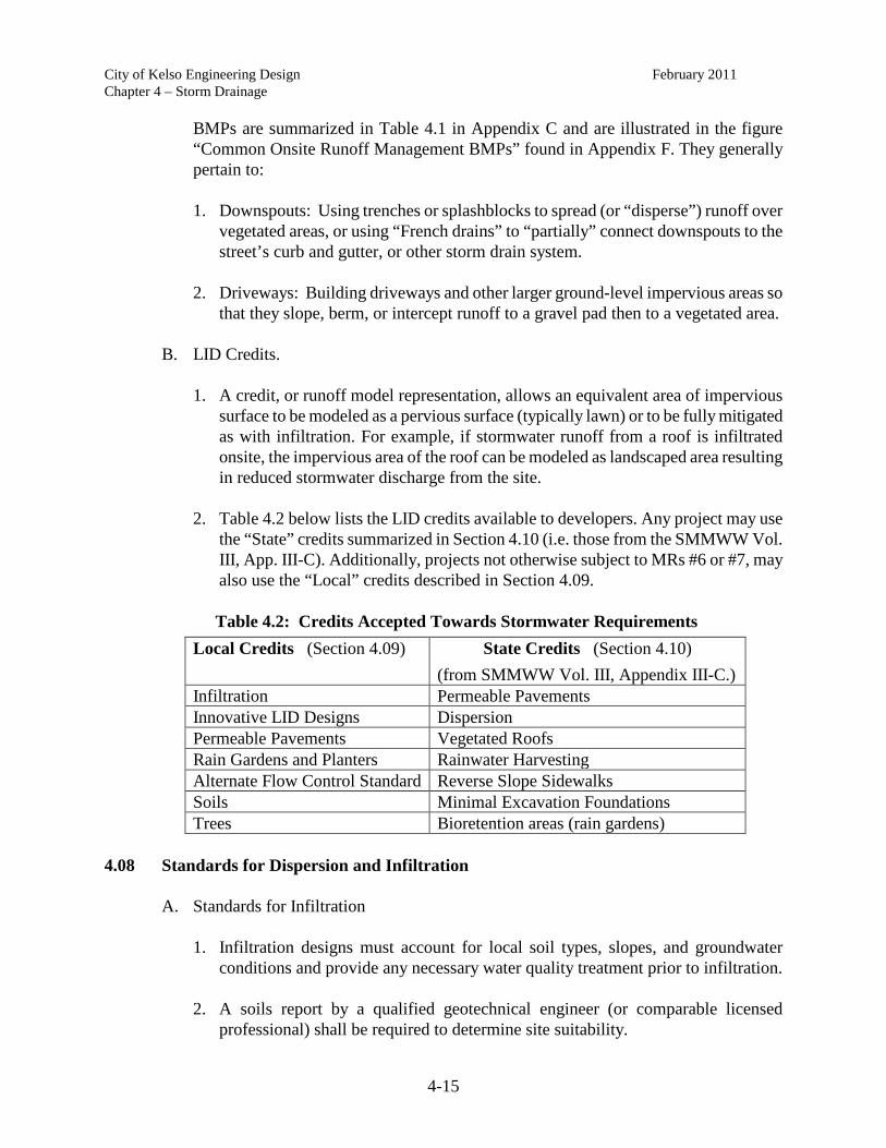
City of Kelso Engineering Design February 2011 Chapter 4 – Storm Drainage
4-15
BMPs are summarized in Table 4.1 in Appendix C and are illustrated in the figure “Common Onsite Runoff Management BMPs” found in Appendix F. They generally pertain to:
1. Downspouts: Using trenches or splashblocks to spread (or “disperse”) runoff over
vegetated areas, or using “French drains” to “partially” connect downspouts to the street’s curb and gutter, or other storm drain system.
2. Driveways: Building driveways and other larger ground-level impervious areas so
that they slope, berm, or intercept runoff to a gravel pad then to a vegetated area.
B. LID Credits.
1. A credit, or runoff model representation, allows an equivalent area of impervious surface to be modeled as a pervious surface (typically lawn) or to be fully mitigated as with infiltration. For example, if stormwater runoff from a roof is infiltrated onsite, the impervious area of the roof can be modeled as landscaped area resulting in reduced stormwater discharge from the site.
2. Table 4.2 below lists the LID credits available to developers. Any project may use
the “State” credits summarized in Section 4.10 (i.e. those from the SMMWW Vol. III, App. III-C). Additionally, projects not otherwise subject to MRs #6 or #7, may also use the “Local” credits described in Section 4.09.
Table 4.2: Credits Accepted Towards Stormwater Requirements
Local Credits (Section 4.09) State Credits (Section 4.10) (from SMMWW Vol. III, Appendix III-C.)
Infiltration Permeable Pavements Innovative LID Designs Dispersion Permeable Pavements Vegetated Roofs Rain Gardens and Planters Rainwater Harvesting Alternate Flow Control Standard Reverse Slope Sidewalks Soils Minimal Excavation Foundations Trees Bioretention areas (rain gardens)
4.08 Standards for Dispersion and Infiltration
A. Standards for Infiltration
1. Infiltration designs must account for local soil types, slopes, and groundwater conditions and provide any necessary water quality treatment prior to infiltration.
2. A soils report by a qualified geotechnical engineer (or comparable licensed
professional) shall be required to determine site suitability.

City of Kelso Engineering Design February 2011 Chapter 4 – Storm Drainage
4-16
3. The design infiltration rate shall be limited to one-half the measured infiltration rate. However, the infiltration rate may be lower; for example, as required by the SMMWW or site conditions. Infiltration rates shall be verified at all sites unless otherwise approved by the Director.
B. Standards for Infiltration and Dispersion
1. No erosion or flooding of downstream properties may result. 2. Roof downspout systems must be downslope of primary and reserve septic
drainfield areas, unless site specific conditions render this unnecessary (e.g. soil permeability, system separations, or site topography prohibits subsurface flows from intersecting the drainfield).
3. Facilities must comply with Ecology’s Underground Injection Control (UIC) wells
program, the Washington Department of Health’s (DOH’s) Wellhead Protection Program, 12/93, and other regulatory protections.
C. Setbacks for infiltration and dispersion shall be according to the Table 4.3 below: Table 4.3: Infiltration and Dispersion Setbacks for Small SystemsFrom Volume III Section 3.1 and Volume V Section 5.3 of the SMMWW
1
Setbacks (from edge of trench/well) Infiltration Dispersion Structure, property line, & sensitive area 10' 2 5' 3 (On, above, or near) Slopes >15% 50' 4, 5 50' 5 (On, above, or near) Slopes >20% - 50' 4, 5 (On, above, or near) Slopes >25% Not Allowed - (On, above, or near) Landslide / erosion hazard areas N/A4 N/A4
Height above seasonal high groundwater 3′ Trench 1′ Drywell
1′ Perforated stub-out
Notes: 1 “Onsite” LID systems typically serving residential downspouts and pavements (e.g. ≥700 square feet per
splashblock and concentrated pavement BMPs, ≥3,500 square feet for dispersion trenches, etc.) 2 For roof downspout systems from significant structures (e.g. house), the setback shall be 15 feet. For
infiltration facilities from building foundations, setbacks are 20 feet upslope and 100 feet downslope. 3 Dispersion BMPs shall be setback 25 feet from the ROW. 4 Requires evaluation by a registered professional civil engineer with geotechnical expertise (geotechnical
engineer) or a licensed geologist, hydrogeologist, or engineering geologist. 5
May be reduced to 15 feet based on geotech evaluation, but never less than the buffer width.

City of Kelso Engineering Design February 2011 Chapter 4 – Storm Drainage
4-17
4.09 Local Credits The following BMPs may be used in lieu of, or to reduce, the local development and
redevelopment requirements. The credits and, to a lesser degree, technical notes for each BMP are provided below:
A. Infiltration. All infiltration shall be considered full treatment, to the degree allowed by
federal and state water quality rules, and as approved by the Director. B. Innovative LID Designs. Projects may receive a credit determined by the Director for
innovative LID designs that are otherwise close to the meeting the local requirements. In the Longview-Kelso area, innovative designs are those that rely primarily on LID or apply particularly salient BMPs such as green roofs, pervious concrete, etc.
C. Pervious Pavements. All pervious pavements may be modeled as landscaping
(including systems with overflow drains) and they may utilize any infiltration and storage within the rock base. To maximize storage and infiltration, the pervious system may be connected to a control structure.
Pervious pavements include pervious concrete, pervious asphalt, and pavers (porous
pavers, specialty pavers patterned for extra void space, or regular pavers sufficiently separated with washed sand/aggregate as to allow the passage of water).
D. Rain Gardens and Planters. Properly designed rain gardens and planters are eligible for
credit similar to the downspout dispersion trench. Facilities serving significant developments, as described in Section 4.03(B)(4)(b), shall be professionally engineered and use quality soils as described in 4.09(F) below.
E. Alternate LID Flow Control Standard. Stormwater designs that manage runoff onsite
(vs. traditional detention approaches) to the maximum extent practicable are allowed to match the full peak release rate of the pre-developed 2-year, 24-hour design storm instead of half that rate. Requirements for the other design storms are unchanged. Designs may include BMPs from the LID Manual or those summarized in the SMMWW Vol. III, Appendix III-C; also refer to Table 4.1.
F. Quality Soils. Pasture that is converted to landscaping may be considered fully
mitigated if its soils achieve Ecology's T5.13 soil quality requirements, typically by augmenting with compost.
G. Tree Credits. The tree credit allows areas using trees to be modeled as landscaping or
forest. Two tree credits are extended to developers. Note that trees on private property, and particularly within a critical area buffer, are regulated by Titles 17 and 18.20 KMC and subject to critical area review. 1. Existing Trees. Preserved existing trees may allow impervious surfaces equal to
half of the tree’s canopy area measured at its drip-line (or the minimum credit for

City of Kelso Engineering Design February 2011 Chapter 4 – Storm Drainage
4-18
public trees below, whichever is greater) to be modeled as landscaping. The tree must:
a. Be in the project area (i.e. onsite), b. Be within 25 feet of an impervious surface or surface water, c. Be at least 4 inch diameter at breast height (DBH), d. Be deemed by a forester certified by the International Society of Arboriculture
(ISA) to be healthy, viable, and compliant with this section, and e. Not be in the ROW landscaping strip or otherwise managed by the City.
2. New Trees. New trees may allow impervious surfaces equal to 100 square feet for
each deciduous tree planted and 200 square feet for each evergreen tree
planted to be modeled as landscaping, subject to the following conditions:
a. The tree must be maintained/replaced in perpetuity by the property owner. For contracts with public entities other than the City, copies of the tree preservation and maintenance agreement and their policies germane to the perpetual maintenance and replacement of trees shall be provided.
b. The tree must be planted within 25 feet of an impervious surface or surface
water. c. Because the time lag between planting and full efficacy of flow control benefits
and a tree’s decreased efficacy during major events, no more than 20 percent of a site’s new impervious surfaces can be mitigated through the use of this credit. All of the replaced impervious surfaces are eligible for this credit.
d. Trees required by the City or other agency (such as street trees) are eligible for
the credit, provided they meet all other requirements of this section. e. The size, species, and location of trees must be consistent with applicable
zoning codes. f. Trees that do not meet the pre-approved list located in Chapter 3 of these
standards shall be approved by the Director prior to approval. g. The tree must be planted either before or as soon as feasible following the
placement of the impervious surface receiving the credit and after activities which may harm the tree or its root zone.
h. The tree must be planted in the same drainage sub-basin as the project. The tree
may be planted in neighboring basins provided the developer demonstrates the

City of Kelso Engineering Design February 2011 Chapter 4 – Storm Drainage
4-19
adequacy of the conveyance system.
3. General Requirements for Credit Trees a. Trees used for stormwater management credit shall be clearly labeled on the
site plans and recorded as any other stormwater facility (see Section 4.16 of this Chapter). Use of trees offsite may be listed in the “Notes” section of the plans.
b. Trees shall be maintained, protected, and replaced for the life of development
or until any approved redevelopment for which a replacement facility is constructed, and subject to the following conditions:
(i) Trees used for stormwater credit shall not be removed without prior
inspection by an ISA-certified City arborist and approval from the Director.
(ii) Trees that are removed or die shall be replaced within six months.
(iii) Replacement size shall be consistent with the standards and procedures of this section, be within the same subbasin, and be of a minimum size or number commensurate with the original credit tree. For example, a tree documented as 1,000 square feet on the plans and drainage report, must be replaced with 10 deciduous or 5 evergreen trees.
c. New or preserved trees shall be marked and protected from land disturbing activities.
d. Trees planted less than 18 feet from a perforated storm drain (or facility)
require the installation of a tree root guard.
4.10 State Credits
A. The most common credit-eligible infiltration and dispersion BMPs from Volume III of the SMMWW, Appendix III-C are summarized in Table 4.1 and are illustrated in the “Common Onsite Management BMPs” figure in Appendix F, with two exceptions:
1. Full dispersion (total exemption) BMPs, which require longer vegetated paths. 2. Roads, sidewalks, soils, and minimal excavation footings.
4.11 Simplified Infiltration Test
The Director may allow this infiltration test for (typically minor) projects not subject to MRs #6 and #7. The test procedure, blank and example data forms are found in Appendix G. Because the test measures a combination of vertical and lateral infiltration, results may

City of Kelso Engineering Design February 2011 Chapter 4 – Storm Drainage
4-20
exceed the true infiltration rate, particularly for larger events. 4.12 General Conveyance Requirements
A. Conveyance, collection, culvert, and bridge design shall accommodate the entire contributing drainage area projected under full build-out conditions and not adversely affect existing downstream conveyance elements and flow conditions.
B. Natural drainage flow routes to streams and wetlands shall be maintained, and
discharges from the site shall occur at the natural location(s) and elevation(s), to the maximum extent practicable.
C. Since open channel conveyance systems can improve water quality treatment, long-term
maintenance, and overland flood relief routes, they may be preferred over closed conduits, if feasible (e.g. space, topography, etc.). Safety considerations must include public access and adjacent travel ways,
D. Outfalls shall enter existing creeks or drainage channels perpendicular to the channel or
angled downstream and have protections to prevent erosion of the existing bank and/or channel bottom during the 100-year design storm.
E. Storm drain conveyance systems shall be installed in accordance with the Longview-
Kelso Special Provisions & Standard Drawings and the current WSDOT Standard Plans and Specifications for Road, Bridge, and Municipal Construction, with the notations as provided in this Section.
F. Discharge to a diking district facility requires the diking district’s approval.
4.13 Closed Conduit Systems
A. Design Requirements
1. The 25-year storm shall show free-flowing conditions through the proposed and/or existing conveyance system.
2. The 100-year storm may overtop the conveyance system, provided:
a. The additional flow shall not extend beyond one-half of the width of the outside lane of the traveled way and shall not exceed a 4-inch depth at the deepest point, and
b. Waters do not rise to elevations more than one foot below that of the lowest
aboveground floor of buildings and no portions of a building will be flooded. 3. Backwater. At the discretion of the Director, or for the conditions listed below, a
backwater analysis shall be conducted to determine the hydraulic grade line to
City of Kelso Engineering Design February 2011 Chapter 4 – Storm Drainage
4-21
ensure a minimum of 1.0-foot freeboard between the water surface and the top of any manhole or catch basin for the 25-year storm:
a. Pipes with slopes less than 0.5 percent, b. Pipes with velocities over 6.5 feet per second (fps) (for sub critical flow only), c. Inlet and outlet pipes forming a sharp angle (45 degrees or greater) at junctions,
and d. Pipe inverts less than 3 feet deep when entering and leaving junctions.
Detailed information on this procedure can be found in Section 6.6 of the WSDOT
Hydraulics Manual (WSDOT 2007) or Section 7 of the Federal Highway Administration (FHWA) Hydraulic Engineering Circular (HEC) 22, “Urban Drainage Design Manual.”
4. Pipe. All storm pipes shall be constructed of high-density polyethylene (HDPE)
smooth interior corrugated pipe.
a. Alternate Materials. Where required for strength, such as for shallow bury (less than 3 feet), Class 52 ductile iron pipe shall be used. Other pipe materials may be used if approved by the Director.
b. Tracer Wire. Plastic pipe shall be laid with marking tape and tracer wire.
5. Size. The minimum pipe size within the public ROW shall be 12 inches unless
otherwise approved by the City Engineer. Storm laterals from private drains to inlets may be 6 inches and shall have a cleanout installed at the property line.
6. Velocity. All storm drains shall be on a grade which produces a mean velocity
when flowing full of at least three fps, unless prohibited by site conditions. The Director may waive this minimum where existing drainage systems make it impractical to meet the standard.
a. If velocities exceed 15 fps during the 25-year storm, anchors shall be provided
at bends and junctions. b. Velocities in pipes other than HDPE and iron are limited to 30 fps.
7. Slope. For slopes steeper than 20 percent, closed conduit systems shall be designed
per Ecology's Criteria for Sewage Works Design. 8. Minimum separations from storm drains to sewers and water lines shall be as
required for sewers in the Longview-Kelso Standard Plans & Specifications, or as approved by the Director. Storm lines shall be laid higher than sanitary sewers

City of Kelso Engineering Design February 2011 Chapter 4 – Storm Drainage
4-22
where possible. 9. Pipes over 8 inches in diameter that “daylight” to the surface shall have a protective
grate installed that prohibits wildlife and children from entering the storm line. The grate shall be hinged or otherwise designed to allow for cleaning and to reduce accumulation of debris from behind the grate.
10. The letter ‘D’ shall be stamped into the curb directly above the point where storm
pipes including, but not limited to, mainlines, culverts, and roof laterals cross under it.
B. Alignment and Cover
1. All changes in direction shall be made at a manhole, or other approved structure. 2. Storm drain lines shall not be curved between structures unless approved by the
Director. 3. Unless otherwise approved by the Director, a minimum cover of 36 inches of cover
is required above the top of the pipe to the top of the ground surface. There shall be a minimum of one 1-foot separation from the top of pipe to the bottom of the roadway section (e.g. laterals from catch basins).
4. In areas of relatively flat terrain, the design engineer must show that sufficient depth
is provided at the boundary of the development to drain the upstream basins. 5. When necessary to locate drains in easements or tracts, the storm drain shall be
centered in the easement. However, drains may be offset due to site conditions. 6. The invert elevation of all upstream pipes shall not be lower than the invert
elevation of the downstream pipe.
C. Manholes
1. Manholes shall be located at all changes in slope, alignment, pipe size, and at all pipe junctions with present or future storm drains.
2. Manholes shall be spaced no greater than 300 feet apart.
3. Standard manholes are required when rim to crown of pipe elevations exceed four
feet, otherwise flat-top manholes shall be used.
4. The manhole cover shall be stamped “STORM.” 5. Manholes shall have a sump with dimensions in accordance with the Longview-
Kelso Standard Plans & Specifications to collect sediment and debris. However,

City of Kelso Engineering Design February 2011 Chapter 4 – Storm Drainage
4-23
manholes having a mainline pipe entering or exiting at a slope of fifteen percent or greater shall have no sump and be pre-channeled.
D. Collection. Stormwater collection systems shall be designed in accordance with the
FHWA’s HEC 22, “Urban Drainage Design Manual,” with the following notes:
1. Curb inlets shall be located in streets at the curb-line to receive stormwater and convey it to the main storm drain.
2. Curb inlets shall be at the following locations, whichever is less, unless otherwise
approved by the Director:
a. Less than 300 feet apart, and in no case shall the spacing be greater than 400 feet,.
b. In the tangent section immediately in advance of the curb returns on the
upstream side of the intersection,
c. At all street ends with a descending grade, and d. At intermediate locations such that gutter flow does not exceed three 3 feet in
width or 3 inches in depth.
3. Catch Basin grates shall be stamped “Dump no Pollutants - Outfall to Stream,” or equivalent.
4. Catch basins shall have a sump at least 15 inches below the lowest invert to collect
sediment and debris. 5. Curb inlets shall be used with curb and gutter installations up to 8% in tangential
grade. Combination curb inlets shall be used for steeper grades.
4.14 Open Conveyance
A. The 25-year storm shall show free-flowing conditions through the proposed and/or existing conveyance system. Culverts with contributing drainage areas greater than 200-acres shall be designed to pass the peak runoff from the 100-year design storm.
B. The 100-year storm may flow at bank-full, provided:
1. Runoff is contained within defined conveyance system elements, 2. The hydraulic grade line does not exceed the elevation of the roadway subgrade,
and 3. Waters do not rise to elevations more than one foot below that of the lowest

City of Kelso Engineering Design February 2011 Chapter 4 – Storm Drainage
4-24
aboveground floor of buildings and no portions of a building will be flooded. C. Culverts. Culverts are regulated under Title 18.20 KMC. Culverts shall be designed in
accordance with the current WSDOT Hydraulics Manual. Fish passage culverts shall meet the design criteria specified in the Washington Department of Fish and Wildlife (WDFW) Design of Road Culverts for Fish Passage.
D. Backwater. A backwater analysis (see the King County Surface Water Design Manual
for an example) shall be performed if a flow restriction (such as a bridge or culvert) causes flow to rise above normal depth within a channel reach.
E. Side Slopes. Channel side slopes shall not exceed 2:1. Depth, safety, and erosion
concerns must be considered with slopes steeper than 3:1. All constructed channels shall be compacted to a minimum 95 percent compaction verified by a modified Proctor test (ASTM D1557/AASHTO T180).
F. Freeboard. Channels designed for 25-year storm flows of 10 cubic feet per second (cfs)
or less shall have at least 0.5 feet of freeboard, and 1.0 feet for greater velocities. G. Lining and Armor. Open channels shall be designed to withstand channel erosion and
not degrade water quality.
1. Channels with peak velocities less than 5 fps shall be vegetated. 2. Channels with velocities above 5 fps shall be sufficiently armored to the maximum
water surface elevation.
4.15 Private Drainage
A. Drainage Accessibility. Subdivision lots which drain to the rear should be avoided; but if necessary to collect roof drains, footing drains, and surface run-off, the developer shall: 1. Provide a recorded stormwater easement for the City inspection of the private
system and/or a recorded stormwater easement for any crossing of private property to reach the approved point of discharge in favor of the upstream landowner.
2. Design and install the system to meet the Uniform Plumbing Code requirements.
B. Stormwater easement geometry shall be in accordance with Section 4.18. C. Use a French drain where feasible to provide some water quality, some peak flow
attenuation, and some dewatering of the property during the wet season. Site suitability shall be determined by an engineer licensed in the State of Washington.

City of Kelso Engineering Design February 2011 Chapter 4 – Storm Drainage
4-25
4.16 Subsurface Drainage
Underdrains shall be provided at the following locations:
A. For all existing springs and tile intercepted during construction. B. Where high ground water exists or when it is necessary to reduce the piezometric
surface to an acceptable level to prevent land slippage or under-floor flooding of buildings.
C. The drainage line installed shall begin at a cleanout and terminate at an approved point
of discharge.
4.17 Curb Drains and Perforated Connections
A. When downspouts and footing drains must be connected to the private or public storm sewer systems, perforated connections (SMMWW Vol. III Ch. 3.1.3) from the home to the property line or curb shall be preferentially used as practicable.
B. Drainage from residential roofs and footings may drain directly to a street via a curb drain under the following circumstances:
1. Perforated connections are used as per 4.17(A) above and designed in accordance
with the SMMWW. 2. It can be shown that gravity drainage is possible. 3. The existing street is adequately crowned and its drainage system, including curb,
gutter, and storm lines, is adequately sized to accept the additional flow. 4. Pressurized outfalls, e.g. sump pumps, shall not be allowed to plume into the street
or where they cause standing pools in the gutter, a slip or a vector hazard. 5. For residential redevelopment, historical installation of curb drains are evident in
the immediate neighborhood. 6. Perforated connections shall not act as a conduit to discharge groundwater or
springs to the storm sewer system. C. Curb drains will be allowed for residential development and redevelopment as
approved by the Director. D. Curb drains shall not be allowed for new commercial development. Commercial
redevelopment may use curb drains as approved by the Director.

City of Kelso Engineering Design February 2011 Chapter 4 – Storm Drainage
4-26
4.18 Tracts and Easements
A. Storm drainage tract dedication and/or easements shall be required where the conveyance (including watercourses), storage, or treatment of stormwater is identified on the stormwater management design plan and/or where: 1. access is needed by the City for inspection and maintenance or to maintain and
inspect stormwater facilities, or
2. access is needed to private drainage per section 4.15 of this Chapter. B. Stormwater tracts and easements shall be placed on all plats and property deeds and
recorded with the Cowlitz County Auditor, after approval by the City. C. Easements shall not be used for any purpose which would interfere with the unrestricted
use of the storm drain line. No structures or other structures that prevent access are permitted within tracts or easements. Fences crossing tracts shall provide gates of sufficient width to provide access for maintenance.
D. Minimum widths for public easements and/or tracts shall be as follows:
1. Storm lines up to twenty-four inches in diameter shall have a minimum easement width of fifteen feet.
2. Storm lines twenty-four inches and greater in diameter shall have a minimum
easement width of twenty feet plus the pipe diameter.
3. Depths greater than seven feet to the invert shall require wider easements. A slope of one horizontal to one vertical (1:1) from the storm drain invert to the ground surface shall be used in determining easement width.
4. Channels with sufficient width to cover the 100-year floodplain line, fifteen feet
from the waterway centerline, or ten feet from the top of the recognized bank, whichever is greater. A fifteen-foot-wide access easement shall be provided on both sides of the channel for channel widths greater than fourteen feet at the top of the recognized channel.
5. Where ROW (or an easement) is required for access, it shall be a minimum of 15ʹ
wide and the tract (or easement) shall extend to an acceptable access location.
4.19 Stormwater Performance Bond
At the discretion of Public Works, the applicant seeking to build a stormwater facility may be required to furnish a stormwater facility performance bond, or equivalent guarantee in lieu of a bond in a form acceptable to the City, in an amount sufficient to cover all costs associated with the construction of the facility. This bond is to secure the installation and performance

City of Kelso Engineering Design February 2011 Chapter 4 – Storm Drainage
4-27
of the stormwater facilities identified in the approved stormwater management design plan. The applicant shall be responsible for any costs incurred by the City to secure performance of the stormwater facilities that are in excess of the amount of the bond.
A. Term of Performance Bond. The stormwater performance bond furnished pursuant to
this section, or the unexpended or unobligated portion thereof, shall be released to the applicant within sixty (60) days of issuance by Public Works of the final acceptance of the permanent stormwater BMP by the Public Works Department. A final inspection by Public Works is required before any performance bond will be released.
B. Term Extended for Initial Maintenance. At the discretion of Public Works, the
stormwater performance bond may be extended beyond the time period specified above to cover a reasonable period of time for testing the BMPs during storm events and for initial maintenance activities. For the purposes of this section, the time shall not exceed 2 years beyond final acceptance of the construction of the BMP, unless the Director determines that an extension is necessary to ensure that the facility satisfies the maintenance and performance requirements identified in the KEDM and the approved stormwater maintenance plan.
C. Partial Release of Bond. The Public Works shall have the sole discretion to adopt
provisions for a partial pro-rata release of the performance bond on the completion of various stages or phases of development.
D. Bond Estimation. The applicant shall be responsible for determining bond value and
submitting the estimation to the Public Works for approval. If the Director disagrees with the applicant’s estimate, the Director shall determine a reasonable estimate. The bond value for public and private facilities is to be 125 percent of the estimated cost for the City to construct the stormwater features and achieve final stabilization.
4.20 As-Built Plans
All applicants are required to submit as-built plans for any permanent stormwater management facilities located on-site after final construction is completed. The plans must show the final design specifications for all stormwater management facilities, meet the criteria for as-built plans in Chapter 1 of this Manual, and be sealed by a registered professional engineer.
4.21 Dedication of Facilities
The City will accept a dedication of a stormwater facility, together with necessary easements and appurtenances, upon a determination and acceptance, as provided herein, except that dedications made during the subdivision platting process shall not be subject to the following process:
A. Preliminary Determination by Public Works. Upon receipt by the City of an offer of
dedication of a stormwater facility, the Director shall make a preliminary determination

City of Kelso Engineering Design February 2011 Chapter 4 – Storm Drainage
4-28
that the dedication of the facility is appropriate to protect the public health, safety and general welfare, and furthers the goals of the City’s stormwater management program and/or associated watershed plans. Budgetary implications will be a component of the determination. The Director will forward his/her determination to the City Council. Prior to making his/her determination, the Director will inspect the facility to determine whether it has been properly maintained and is in good repair, and may condition the recommendation of acceptance on completion of any necessary maintenance items.
B. Acceptance by City Council. City Council may reject or accept the offer of dedication by adoption of a resolution. Upon acceptance, the owner shall record the document dedicating the stormwater facility with the Cowlitz County Auditor by and at the owner's sole expense.
C. Owner to Provide Documentation. The owner, at his or her sole expense, shall provide any document or information requested by the Director and/or the City Council in order for a decision to be reached on whether or not to accept the facility.
4.22 Long-Term Operation and Maintenance
A. Operation and Maintenance Required. All erosion controls, watercourses, and stormwater facilities (including, but not limited to, structural and non-structural BMPs, catch basins and other protective devices, necessary access routes, and appurtenances) shall be operated and maintained in accordance with the manufacturer’s specifications, the SMMWW, this Manual, the approved stormwater management design plan, and the stormwater maintenance agreement and plan, as discussed below.
B. Responsible Party. The owner shall be responsible for the proper operation and
maintenance of the site’s stormwater facilities and shall pass such responsibility to any successor owner, unless such responsibility is transferred to the City as per section 4.21 of this Chapter.
C. Operation and Maintenance Agreement and Plan. The owner of a stormwater facility
shall execute a Stormwater Operation and Maintenance (O&M) Agreement and Plan prior to final acceptance of the project (see Appendix H for an example). The agreement shall be approved by the City and recorded with the Cowlitz County Auditor and shall run with the land. The agreement and plan shall, at a minimum, have the following:
1. Designate the responsible party permanently responsible for maintenance. 2. Pass the responsibility for such maintenance to successors in title. 3. Grant the City and its representatives the right of entry for the purposes of
inspecting all stormwater BMPs at reasonable times and in a reasonable manner. This includes the right to enter a property when Public Works has a reasonable basis to believe that a violation of this Chapter is occurring or has occurred and to

City of Kelso Engineering Design February 2011 Chapter 4 – Storm Drainage
4-29
enter when necessary for abatement of a public nuisance or correction of a violation of this Chapter.
4. Establish an operation and maintenance plan to ensure the continued effectiveness
of the BMPs. This plan shall, at a minimum, include site and facility plans, relevant detail sheets, technical description(s), a list and schedule of inspection and maintenance tasks, and actions to be taken when maintenance is required (e.g. standard procedures).
5. Include copies of any educational brochures required in Section 4.22 (G).
D. Maintenance Escrow Requirement
1. At the discretion of the Director, the property owner will be required to post a cash escrow, letter of credit, or other acceptable form of performance security in an amount that would cover costs associated with maintenance and repair in the event of stormwater facility failure, at least 10% of the project engineer’s estimate to construct the facility, in the event the Director determines that such security is necessary to ensure the facility satisfies the maintenance and performance requirements identified in the KEDM and the approved stormwater maintenance plan. This instrument is required to be posted prior to completion of construction and release of the Stormwater Performance Bond and remain in place for a minimum of two (2) years.
2. At the discretion of the Director, the stormwater performance bond may be
extended in lieu of the maintenance escrow account. E. Maintenance Records. The responsible party shall keep records of the BMPs’
installation and all subsequent maintenance and repairs, and shall retain the records for at least five (5) years. These records shall be made available to the City within 1 week of inspection or upon request by the City.
F. Deeds and Covenants for LID. Private homeowner deed restrictions and
homeowners/building covenants shall be required for all properties with on-site LID BMPs to ensure that the stormwater management applications continue to function as designed. The deed restrictions or covenants shall specifically address and/or append the requirements and responsibilities for long-term management and maintenance of any LID BMPs. Sample covenant language is provided in Appendix H.
G. Stormwater Education
1. The developer shall create education measures, for example, fact sheets or brochures, for stormwater flow and treatment controls (including conservation areas and LID BMPs) that serve multi-unit residential developments. The literature shall provide the following:

City of Kelso Engineering Design February 2011 Chapter 4 – Storm Drainage
4-30
a. A plan describing the facility (or BMP), its location, function and purpose.
b. Technical information necessary to ensure long-term performance, including but not limited to, soil characteristics, tree and plant species, and maintenance instructions.
c. Information on any management agreement and plans. d. Contacts for questions on maintenance needs and enforcement.
2. The developer shall provide copies of the educational materials first to the City for approval and filing prior to final acceptance of the project, and then to the initial property owner upon sale of the property. The City may provide a copy of the brochure or guide to successive owners or incorporate the material into its public education and outreach program.
4.23 Enforcement
Enforcement shall be consistent with KMC 13.11.
A. Protection of Watercourses and Facilities. It shall be a criminal violation to break, block, damage, destroy, uncover, deface or tamper with any watercourse, stormwater facility, or erosion control system.
B. Public Nuisance Declared. In addition to other remedies, failure to install and/or maintain watercourses, stormwater facilities, or erosion controls as required in this Manual and applicable permits is declared to be a public nuisance, subject to abatement as provided by KMC 13.11.
C. Suspension of Work or Access
1. Access to the municipal stormwater drainage system may be suspended if such termination is needed to abate or reduce an illicit discharge.
2. Work shall be suspended for un-permitted clearing and grading, or for projects that
fail to provide required runoff controls for land disturbing activities. After the stop-work period, the Director may allow work on-site to recommence, provided that such work is necessary to ensure compliance with this Manual, permits, or an approved stormwater drainage plan or SWPPP.
3. Resumption of work or reinstatement of connection to the municipal stormwater
drainage system, without the prior approval of the City, shall be subject to the civil and/or criminal penalties delineated in KMC 13.11.
D. Financial Liability. The property owner and all persons engaged in development or
land-disturbing activity shall be liable, jointly and severally, for all costs incurred by the

City of Kelso Engineering Design February 2011 Chapter 4 – Storm Drainage
4-31
City in any public nuisance action taken hereunder, or on account of damage or threatened damage to City property or facilities or water bodies, or associated with remedial actions necessitated by the damage or failure to install and/or maintain required stormwater facilities. The City may assess the responsible parties for these costs which shall be a lien on the property, or prorated against the beneficial users of the property, and may be placed on the tax bill and collected as ordinary taxes by the City.

Chapter 5
Water
City of Kelso Engineering Design Manual
June 2008 City Engineer: Sharon Zimmerman, P.E.

Chapter 5 Water
City of Kelso Engineering Design Manual
June 2008
Table of Contents
Page Description No. 5.00 Utility Easements and Tracts ..................................................................................................1 5.01 General Design Considerations................................................................................................1 5.02 Sizing and Pressure Requirements ...........................................................................................3 5.03 Shut-off Valves ........................................................................................................................4 5.04 Air-Release Valves ..................................................................................................................4 5.05 Hydrants ...................................................................................................................................4 5.06 Water Meters ............................................................................................................................4 5.07 Fees and Charges .....................................................................................................................6 5.08 Cross Connection Control ........................................................................................................6 5.09 Contract for Reimbursement (Latecomer Agreements) ...........................................................6 5.10 Water Quality ...........................................................................................................................6 5.11 Plans and Specifications ..........................................................................................................6 5.12 Connections to Existing Pipelines ...........................................................................................7 5.13 Roadway and Railway Crossing ..............................................................................................7 5.14 Trench Excavation ...................................................................................................................8 5.15 Pipe in Filled Areas ..................................................................................................................8 5.16 Pipe Installation for Water Mains ............................................................................................8 5.17 Bedding and Backfill ...............................................................................................................9 5.18 Hydrostatic Tests .....................................................................................................................9 5.19 Sterilization and Flushing of Water Mains ............................................................................10 5.20 Cross Connection Control and Backflow Assemblies ...........................................................10 5.21 Requirements for Water System Vault Installations ..............................................................12 5.22 Fire Services and Domestic Services .....................................................................................13 5.23 Special for Fire Service Only .................................................................................................13 5.24 Water Meter Vaults ................................................................................................................14 5.25 Pressure Reducing Valve Vaults ............................................................................................14 5.26 Appurtenances........................................................................................................................14

Chapter 5 Water
City of Kelso Engineering Design Manual
June 2008
Table of Contents
Page Description No. Tables Table 5.1 – Maximum Deflection Permitted 18-Foot Length Pipe .................................................9

City of Kelso Engineering Design Manual Chapter 5 – Water June 2008
5-1
CHAPTER 5 - WATER 5.00 Utility Easements and Tracts
All public utilities (storm, water, and sewer) shall be in public right-of-way, utility easements or tracts. Easement and tract width shall be a minimum twenty (20) feet. No obstructions including but not limited to fences or retaining walls are to be located within the easement or tract. 5.01 General Design Considerations
A. In all developments water main extensions and looping are required to assure orderly development of the water utility system. Where applicable, water main extensions shall conform to the requirements of the City’s latest approved Water System Plan. Where the proposed extension is not addressed in the Water System Plan, the Applicant shall pay the cost for any Water System Plan amendments required by the Washington State Department of Health, or City Engineer. All proposed water main extensions must comply with the City's requirements for development, water quality and pressure zones, and fire protection requirements of the City. The proposed main extension shall be designed by a licensed engineer and be approved by the city engineer and appropriate governmental authorities. The design shall be in conformance with the city standards and shall be designed by the use of a hydraulic analysis considering pipe size, restrictions, peak demand, length of run, elevation differences, the availability of water in the existing mains, reservoir capacity, pressures in the area, other local conditions and other factors as may be pertinent. If the extension is considered feasible, then the pipe diameter and other conditions shall be determined by the analysis. A meeting with the City Engineer shall be required prior to acceptance of the hydraulic analysis to help determine minimum requirements for the hydraulic analysis report.
B. Design and construction of water mains, including but not limited to, mainlines,
valving, fire hydrants, fire sprinkler connections with backflow devices, domestic and irrigation services, pump stations, pressure reducing stations, telemetry and other appurtenances shall be in compliance with the City ordinances, special requirements of the City, these Standards, and the Standard Details.
C. All service laterals, 2” and smaller, shall be copper type K. All water mains and service
laterals larger than 2” shall be Ductile Iron., D. The applicant is responsible for designing the proposed water system(s). The system(s)
must be designed by a licensed engineer and approved by the City. E. Water mains shall be extended through and to the extremes of the property being
developed for gridding or future development, as determined by the City. F. The City discourages dead end water main extensions. Unless specifically approved by

City of Kelso Engineering Design Manual Chapter 5 – Water June 2008
5-2
the City Engineer, all water main extensions shall be looped to other water mains within the pressure zone of that water main extension. Generally, looping of water main extensions is required for all extensions serving twenty (20) or more equivalent residential units.
G. The City discourages water main extensions for service to pressure zones different from
the pressure zone from which the extension is made. Unless specifically approved by the City Engineer, booster pump stations or pressure reducing valve stations shall not be permitted.
H. Water mains parallel to a sewer shall be above and separated by a distance of ten feet
horizontally.
Under unusual circumstances, the horizontal spacing may be adjusted subject to the approval of the director of public works. Water mains crossing sewers should not be less than three feet above the sewer. Where it is necessary for a sewer to cross within eighteen (18) inches or over the water main, the sewer shall be constructed of ductile iron for a distance of ten feet on either side of the water main as approved by the director of public works. At no time shall the water main design not be in accordance with the DOE Orange Book.
I. Rights-of-way or easements shall be provided to the City for access and maintenance of
all conveyance systems, or other facilities as deemed appropriate by the City Engineer, within the development site, which are to be maintained by the City. The minimum widths of rights-of-way or easements shall be as follows, although the City Engineer may require increased widths when necessary to insure adequate area for equipment access and maintenance:
1. Pipes with an inside diameter less than or equal to thirty-six (36) inches: twenty
(20) feet; 2. Pipes with an inside diameter greater than thirty-six (36) inches: twenty (20) feet or
larger as required by the City; 3. Pipes shall be centered within the right-of-way or easement; 4. Pipes with more than a seven (7) foot depth to the invert shall require wider
easements. A slope of one (1) horizontal to one (1) vertical from the storm drain invert to the ground surface shall be used in determining easement width.
No buildings or other structures that prevent access are permitted within rights-of-
way or easements. Fences crossing rights-of-way shall provide gates of sufficient width to provide access by maintenance vehicles.

City of Kelso Engineering Design Manual Chapter 5 – Water June 2008
5-3
When possible, easements for apartment complexes or commercial/industrial developments shall be in parking lots, private drives, or similar areas that allow unobstructed vehicle access for maintenance.
. 5.02 Sizing and Pressure Requirements
A. In areas where gridding or fire flow is a requirement, 8-inch diameter pipe will normally be required. Nothing shall preclude the City from requiring the installation of a larger sized main if the City determines a larger size is needed to meet fire protection requirements or for future service. The Applicant shall be required to pay the cost of all oversizing. Reimbursement for oversizing will be in accordance with the KMC.
B. An adequate grid for eight (8) inch pipe shall measure no more than six hundred feet on
one side and the sum of two sides shall not exceed nine hundred feet. Necessary fire flow, as recommended by the fire department, shall be considered and pipes shall be sized to meet these requirements. Where a grid is not established, pipe size shall be of a diameter suitable to carry the peak daily demand plus the required fire flow.
C. Dead end mains normally shall not be allowed. When they are permitted, a blow off
assembly will be required. In the event that the "dead end" finishes where there is risk of a vacuum being created due to water shut down, then a Combination Air and Vacuum Release Valve shall be installed in accordance with the Standard Drawings.
D. All water system installation shall be designed to provide a pressure range at the
residence of thirty (30) psi to ninety (90) psi at all times, including during peak demand, unless specifically approved.
E. An approved screen shall be located in the pressure reducing valve vault at a location
upstream of the pressure-reducing valve. Pressure reducing valves may be required at the discretion of the City on individual services. Such valves will be installed after the meter and will be the responsibility of the homeowner to install and maintain.
F. Water service size shall be evaluated by the applicant's engineer. The requirements of
this section shall be met and shall be no smaller than 1-inch. Booster pumps shall not be allowed on meter service lines in order to meet this requirement, unless specifically approved by the City Engineer.
G. Where requested by the City Engineer, the applicant's engineer shall provide a "pressure
available" chart on the water system plan sheet of the construction plans. This sheet shall indicate the calculated pressures theoretically available to each lot during static and peak demand periods. In such cases it shall be the Applicant's engineer's responsibility to determine pressures based upon an analysis of the system. All work associated with the analysis shall be paid for by the Applicant.
City of Kelso Engineering Design Manual Chapter 5 – Water June 2008
5-4
5.03 Shut-off Valves
A. Valves shall be located, whenever possible, at intersections (one (1) valve per each line radiating from the intersection). In general, sufficient valves should be provided to permit shutting down any section of the line, not exceeding five-hundred (500) feet, with valve operations in not more than three (3) locations.
B. Valves shall be installed in clusters at pipeline intersections. C. Valves 8-inches and smaller shall be resilient seat gate valves. D. Valves 10-inches and greater shall be butterfly valves.
5.04 Air-release Valves At high points in the water system, combination air and vacuum release valves (CARV) shall be installed as required by the City Engineer. All Air-Vac, Air Evacuation, and Vacuum Prevention Valves of sizes two (2) inches and larger shall vent to the outside of the vault. If construction of the valve does not permit the venting of leakage to the outside of the vault, a screened drain to daylight of at least the supply line size must be provided at a level that will prevent cross connection and/or backflow problems. This decision will be made by the City Engineer prior to the plan approval.
5.05 Hydrants
A. The number and locations of fire hydrants, fire flow requirements, and fire sprinkler components will be recommended by the Cowlitz Fire Department District #2. Following are general requirements for fire hydrant locations:
1. Commercial Buildings: Fire hydrants shall be located so that no part of a
commercial building is more than two-hundred and fifty (250) feet from a fire hydrant measured along a route accessible to fire department vehicles. When a fire department connection (FDC) is installed in conjunction with an automatic sprinkler system, it is required to have a fire hydrant located within seventy (70) feet of the FDC.
2. Non-Commercial Buildings: Fire hydrants shall be placed at a minimum at each
street intersection. The Fire Marshall may request additional hydrants per Fire Code requirements.
3. Intermediate hydrants are required when the distances to any part of noncommercial
buildings exceeds five-hundred (500) feet measured along a route accessible to fire department vehicles.
B. Fire hydrants shall not be connected to mains less than 8-inches, or 6-inches in diameter
where the length of 6-inch main is less than two-hundred (200) feet. As per the IFC,

City of Kelso Engineering Design Manual Chapter 5 – Water June 2008
5-5
fire hydrants shall be located to allow a 5-foot clear space surrounding the hydrant. For example, street lights, sign posts, protective posts, or retaining walls shall be no closer than five (5) feet from the nearest portion of a hydrant. There shall also be no obstructions directly in line with any of the ports of the hydrant.
C. Fire hydrants shall have Storz fittings (or approved equal). D. Fire hydrants subject to possible vehicular damage shall be adequately protected with
guard posts in accordance with Uniform Fire Code Section 8001.11.3. For marking, see Section 901.4.3. For obstruction, see Section 1001.7.
5.06 Water Meters
A. Water meters sized ¾-inch and 1-inch shall be furnished and set by the City. The owner is required to make application and pay meter fees prior to the installation. The City will install meters and lock off meter setters and turn on as requested by the owner after acceptance by the City.
B. Meters 1 ½ -inch and larger will be installed by the owner as part of the construction
project and provided to the City Operations for testing and approval prior to installation. After testing and approval the applicant’s contractor shall install.
C. Water meters will be set only after curb stop and box are at proper finished grade, an
approved sanitary sewer or septic has been installed and accepted, a water use questionnaire has been approved, and all fees have been paid. All meters shall remain the property of the city.
D. Meters shall be located outside of the sidewalk and/or drivepath at the edge of public
right-of-way, in the landscape strip or as otherwise approved by the City Engineer. Meters and services shall be relocated if a driveway or crossing is to be constructed over the existing service.
E. Meters located within county right-of-way shall be within the county right-of-way and
within two (2) feet of the property line nearest the customer’s premises. F. In situations in which the above meter locations do not apply, or if locating the meter
according to the above standards pose a risk to public safety or creates an undue hardship, the location of the meter(s) shall be approved by the City Engineer
G. All irrigation systems require the installation of state certified backflow devices. All irrigation meters will be set and turned on after acceptance of the water system by
the City. The City will not accept a water system until all the requirements of the Extension Agreement have been completed and all the fees have been paid.

City of Kelso Engineering Design Manual Chapter 5 – Water June 2008
5-6
H. Adjustments, repairs, or replacement of the service line, meter box, or setter shall be the responsibility of the property owner.
I. Water services are to be single runs from the main line to each meter. Manifolds with
multiple meters shall be allowed in multi-family units with a single property owner or on commercial/industrial sites with a single owner as approved by the City Engineer. The location of all water services crossing curbs shall be indicated by a “W” stamped into the concrete curb.
5.07 Fees and Charges All fees and charges related to development shall be in accordance with the latest requirements of the KMC. 5.08 Cross Connection Control
A. All water system connections to serve buildings or properties with domestic water, fire sprinkler systems, or irrigation systems shall comply with the minimum backflow requirements as established by the Department of Health (DOH), WAC 246-290-490, and the City.
B. Backflow devices shall be installed in accordance with the requirements of the
"Accepted Procedure and Practice in Cross Connection Control" manual, the Uniform Plumbing Code, Chapter 6 Washington State Amendments 603.0.
5.09 Contract for Reimbursement (Latecomer Agreements) Should the Applicant deem that the utility extension is an undue hardship and will significantly benefit other property owners, the Applicant may request a latecomer agreement, in accordance with the KMC. 5.10 Water Quality The quality, taste, and odor of water drawn from new construction water mains shall be the same as the water in the existing facility classed as acceptable for use by the City. Should the water not be acceptable for use because of taste, required steps as approved by the City shall be accomplished to attain water quality acceptable for use. Sampling for such water quality testing shall be performed by the use of a Kupferle (model #88 Eclipse) sampling station installed permanently and specifically for such testing. A sampling station shall be required for every fifty (50) EDU’s or as determined by the City Engineer. The location for said sampling stations will be determined by the City Engineer. 5.11 Plans and Specifications
All extensions to the water system shall conform to the most recent edition of the Standard Specifications for Road, Bridge, and Municipal Construction. The system shall be capable of future

City of Kelso Engineering Design Manual Chapter 5 – Water June 2008
5-7
expansion and be constructed of permanent materials. The installation of water extensions shall be in accordance with construction plans and specifications prepared by the Applicant's engineer and reviewed and approved by the City. Where conflicts exist the more stringent specification shall apply as approved by the City. 5.12 Connections to Existing Pipelines
A. Connections shall only be allowed to existing mains. Connections to existing mains will only be allowed after receiving approval from the City Engineer. Upon the presentation to the City Engineer of the treasurer’s receipt for service charges and the execution of the agreement, the City Engineer shall cause the premises described in the application to be connected to the City’s water main.
B. Connections may be made to existing pipes under pressure with a tapping machine by
determining the size and type of pipe and installing tapping sleeve to fit complete with tapping valve. Where cut-ins are permitted to be made in existing pipes, the work shall be conducted at such a time and in such a manner as to minimize the interruption of service. Cut-in time must be approved by the City. Necessary pipe, fittings, and gate valves shall be swabbed with chlorine and assembled at the site ready for installation prior to the shutting-off of water in the existing main. Once the water has been shut off, the work shall be performed vigorously, to minimize the interruption, and shall not be halted until the line is restored to service. Operation of all water main line valves shall be by the City. The City shall witness all wet taps and cut-in connections and requires forty-eight (48) hours notice and approval by the City.
C. The Contractor shall have the responsibility of giving written notice to the City at least
four (4) days and to affected customers at least 48-hours prior to disruption of service. Written notice to affected customers shall consist of, at a minimum, door hangers, as well as signs posted at the entrance to the customers streets of the impacted area.
D. Pipes to be abandoned shall be removed or capped with mechanical couplings, as
determined by the City Engineer. E. Service connections shall extend at right angles from the main to the property line. The
city connection which shall include a ball corp stop, a ball valve, and an angle ball valve shall be placed within the curbline and the meter set assembly in conformance with these Standards and the Standard Details.
5.13 Roadway and Railway Crossing The owner shall use the method, which has been designed on the plans and is acceptable to the City and the government or private agency having control of the road. Permits are required and a copy shall be provided to the City.

City of Kelso Engineering Design Manual Chapter 5 – Water June 2008
5-8
5.14 Trench Excavation
A. Clearing and grubbing where required shall be performed within the easement or public right-of-way and as permitted by the property owner and/or governing agencies. Debris resulting from the clearing and grubbing shall be disposed of by the Applicant.
B. Trenching for water mains shall be completed in accordance with the Standard
Specifications. C. Trenching and shoring operations shall not proceed more than one-hundred (100) feet
in advance of pipe laying without written approval of the City. D. Where a utility crosses under an existing asbestos cement water main or where a trench
alters the bedding of an existing asbestos cement water main, the existing A.C. pipe shall be cut three (3) feet minimum from each side of the trench wall and replaced with a corresponding size ductile iron pipe Class 52. The ductile iron pipe shall be connected to A.C. pipe with transition couplings.
E. Contractor shall furnish a watertight plug of the appropriate size which shall be
installed in the end of water main when work is delayed or stopped at the end of the work shift.
5.15 Pipe in Filled Areas Where pipe is to be installed in filled areas, special treatment may be required at the discretion of the City. This treatment may consist of compacting the backfill in 6-inch layers, careful choice of backfill materials, use of Mechanical Joint Ductile Iron Pipe in short lengths, or such other reasonable method or combinations as may be necessary or as required by the City. 5.16 Pipe Installation for Water Mains The work necessary to excavate, bed, and backfill water pipelines shall conform to the requirements of the Standard Specifications and the Standard Drawings.
A. Pipe and Fittings Use only Class 52 ductile iron pipe and fittings in accordance with the Standard
Specifications. B. Permissible Deflection of Joints Wherever it is necessary to deflect pipe from a straight line either in a vertical or
horizontal plane, or where long-radius curves are permitted, the amount of deflection allowed shall not exceed the values in the following Table 1 Section 5.18B:

City of Kelso Engineering Design Manual Chapter 5 – Water June 2008
5-9
Table 5.1
Maximum Deflection Permitted* 18-Foot Length Pipe
Dia. In.
Mechanical Joint** Maximum Deflection
Push-on Joint Maximum Deflection
Angle Degrees
& Minutes Deflection
Inches Angle
Degrees Deflection
Inches 4 8-18 31 5 18 6 7-07 27 5 18 8 5-21 20 5 18 10 5-21 20 5 18 12 5-21 20 5 18
* The maximum deflection shall be whichever is less; the table or that recommended by the pipe manufacturer. ** Safe deflection for one hundred and fifty pounds (150 lbs.) pressure. For higher pressure, reduce tabulated deflection proportionally ten percent (10%) for each one hundred and fifty pounds (150 lbs.) added pressure.
5.17 Bedding and Backfill Use imported bedding for all water main pipe installed under pavement, curbs, sidewalks, or usable shoulder. Bed and backfill pipe and appurtenances in accordance with the Standard Specifications. 5.18 Hydrostatic Tests The Contractor shall make pressure and leakage tests on all newly laid pipe. Test to be made at two hundred and fifty (250) psi for 2-hour with acceptable loss in accordance with WSDOT standard specifications. Test at higher pressures may be required depending upon installation. Furnish all necessary equipment and material, make all taps in the pipe as required, and conduct the tests. The City shall witness the test; if the test does not pass inspection for any reason, additional trips required to witness the test shall be at the owner's expense.
A. Correction of Excessive Leakage Should any test of pipe laid disclose leakage greater than that allowed, locate and repair
the defective joints or pipe until the leakage of a subsequent test is within the specified allowance. The leakage allowed during a test shall be in accordance with the Standard Specifications.

City of Kelso Engineering Design Manual Chapter 5 – Water June 2008
5-10
B. Isolation of Existing Systems Prior to Testing Existing water pipelines shall be protected from contamination during the testing
process for new construction. The newly installed water line shall only be connected after it has passed pressure and dechlorination tests. Use of special "blind flanges" will be necessary if the line being tested cannot be adequately separated from existing systems. The Applicant's engineer shall submit shop drawings and proposed procedures to the City prior to installing any special testing device.
5.19 Sterilization and Flushing of Water Mains Pipeline intended to carry potable water shall be sterilized before placing in service. Sterilizing procedures shall conform to the standard specifications as hereinafter modified or expanded.
A. Disposal of Sterilizing Water Dispose of sterilizing water in an approved manner. Do not allow sterilizing water to
flow into a waterway without adequate dilution or other satisfactory method of reducing chlorine to a safe level. Dechlorinization procedures are to be submitted in writing and approved by the City Engineer prior to flushing system.
5.20 Cross Connection Control and Backflow Assemblies An approved backflow prevention assembly, as listed in “Backflow Prevention Assemblies for Installation in Washington State” (DOH PUB 331-137), is required on all fireline systems, domestic water service larger than 2-inches, and/or building in excess of thirty (30) feet above the water main. The assembly shall be installed at the location normally established for water meters, usually at the property line. A water service shall not be turned on until all required backflow prevention assemblies are installed, inspected, tested, approved, and registered with the City of Kelso. Costs of all installations, including all costs of inspection and testing fees, shall be the responsibility of the customer. The backflow prevention assembly will remain the property of the customer. The customer will be responsible for all maintenance and testing of the assembly and vault for the life of the assembly. When required, backflow prevention assemblies for protection of the public water system shall meet the requirements set forth in the current Washington State Department of Health regulations, Uniform Plumbing Code, and City ordinances. All installation shall meet AWWA Cross Connection Control Manual, May 1990, requirement. The type of backflow prevention assembly required is determined by the aforementioned rules and codes, based on the type of premises to which water service is being provided. The approved types of assemblies are listed below with some of the types of premises that must be protected by each type of assembly. However, these lists are not complete, they are only intended to provide some basic guidelines.

City of Kelso Engineering Design Manual Chapter 5 – Water June 2008
5-11
A. Reduced Pressure Backflow Assembly An approved Reduced Pressure Backflow Assembly shall be installed on the service
connection above ground to the following:
1. Any parcel or building that has an auxiliary water supply on or available to it. This will include any above or below ground water source. (The most commonly encountered type of auxiliary water supply is a private well);
2. Buildings which are located within an industrial zone; 3. Hospitals, medical centers, and clinics; 4. Mortuaries and nursing homes; 5. Gas stations; 6. Car washes; 7. Sewage pump and lift stations; 8. Dry cleaners and commercial laundries; 9. Any water system which has a pump to supplement pressure; and 10. Irrigation systems, which are designed to use chemical injection.
B. Double Check Assembly or Double Check Detector Assembly An approved double check assembly or an approved double check detector assembly
shall be required (provided that all internal plumbing is installed and maintained in accordance with the Uniform Plumbing Code), on the service connection to premises where there is:
1. Any fire system or water line to a private fire hydrant; 2. Multi-story buildings which are in excess of thirty (30) feet above the water main at
the service connection; 3. Shopping centers or large retail stores; and 4. Restaurants or fast food establishments.

City of Kelso Engineering Design Manual Chapter 5 – Water June 2008
5-12
C. Installation and Testing
Backflow prevention assemblies shall be installed at the water service connection on the customer side of the meter. Backflow prevention assemblies 1-inch and smaller shall be installed in a heated and/or insulated enclosure capable of providing year-round freeze protection, sized to meet the clearance requirements as shown in the Kelso/Longview Standard Plans and Specifications. After installation, all backflow prevention assemblies that are installed must be tested upon installation by a State of Washington certified tester. The results of the testing shall be received by the City prior to issuance of "final occupancy." Backflow prevention device assembly vaults shall be constructed in accordance with the standard drawings and requirements of this section. Backflow vaults shall be on private property and located outside of public easements.
5.21 Requirements for Water System Vault Installations To ensure proper operation and accessibility of all assemblies, the following requirements shall apply to installation of these assemblies, unless otherwise approved by the City. Vaults shall be constructed per the Standard Details.
A. The vault shall be sealed with an asphalt base foundation coating on the outside of the vault. Vault penetrations shall be sealed with non-shrink grout from the outside.
Apply waterproof coating over grout. Backfill around vault per the manufacturer's specifications.
B. Access shall be through an H-20 rated hydraulic assist locking hatch of minimum size
36” x 60” locking open at 90°. Hatch is to be leak proof, gasketed, double raise and made of aluminum.
C. Provide approved ladder if the vault or chamber depth is 5’0” or greater and entry is
through the vault or chamber roof. Ladders shall include a Model 1 Bilco LadderUP safety post or approved equal.
D. Adequate drainage for the vault or chamber shall be provided. (Drainage to piped
storm systems allowed with check valve). E. Vault must be equipped with a moisture proof light fixture if adequate lighting is not
available. F. Vault is to have no other use, except for use described by these Standards. G. Vault shall be installed on undisturbed base or compacted 3/4"-0" gravel base.

City of Kelso Engineering Design Manual Chapter 5 – Water June 2008
5-13
H. No piping shall be installed in excess of three (3) feet above the vault floor. I. Assembly is to be adequately supported from the floor, and suitably restrained from
movement. Supports shall consist of steel supports or approved equal; no wood supports shall be used.
J. All electrical wiring shall be inspected by the Washington State Electrical Inspector
(Permit is required). K. The assembly shall be readily accessible with adequate room for maintenance. L. All new services are to be pressure tested and disinfected by the contractor and proven
to be bacteriologically safe from the existing main to the vault.
5.22 Fire Services and Domestic Services
A. No part of the backflow prevention assembly shall be submerged in water or installed in a location subject to flooding. In a vault or chamber, adequate drainage shall be provided; and test cocks shall be plugged. The plugs shall not be of dissimilar metals.
B. The backflow assembly shall be protected from freezing and other severe weather
conditions. C. All backflow assemblies shall have a minimum twelve (12) inch clearance on the
backside, Twenty-four (24) inch clearance on the test-cock side and twelve (12) inches below the assembly.
Adequate clearance of at least six (6) inches must be maintained above gate-valve stem
at full extension. Headroom of six (6) feet is required in vaults without a full opening top. Access to the device and to any vault or chamber shall remain clear at all times.
D. No more than one (1) premises shall be served by any one (1) fire service. E. Fire services shall be metered at the expense of the owner. Detector check meters shall
be installed on automatic fire sprinkler services which may include hose racks inside the building; size and type shall be approved by the City. Double Check Detector Assemblies shall be installed on all fire services where hydrants are installed.
5.23 Special for Fire Service Only
A. Fire Service backflow prevention assemblies shall be installed at the property line or edge of the public water line easement. The fire service from the public main to the backflow assembly shall be publicly owned and meet all City's Standard Drawings.
B. Only approved resilient seat indicating valves are allowed on fireline assemblies.

City of Kelso Engineering Design Manual Chapter 5 – Water June 2008
5-14
C. Only approved Double Check Detector Valve Assemblies are to be used for system
containment on fire line services in the City. The meter on the bypass detector shall read in cubic feet.
D. Fire Line Flow and Tamper Switches installed, as required by UBC sec. 3803, must be
connected to a monitored Fire Detection System approved by the Fire Marshal. The tamper switches are required on the rising stem gate valves in the vault, as well as any other indicating control valves on the fire protection system. Electrical inspection and permit is required.
E. The remote reader (if allowed) shall be rigidly mounted on an exterior building wall
(near the domestic meter), enclosed in a metal box with a slot opening which allows reading the remote without opening the box, and at an elevation of five (5) feet above the ground level.
The remote reader shall have the same number configuration as the metering device
itself, and read in cubic feet. All wires to the remote reader shall be enclosed in a heavy plastic or rigid metal conduit. All wiring shall be in conformance with appropriate sections of the National Electric Code.
5.24 Water Meter Vaults The vault is to be provided and installed by the Contractor, per Standard Drawings. 5.25 Pressure Reducing Valve Vaults PRV vaults are unique to each situation. The engineer shall detail the vault on the plans and submit for review. The City will review the vault for size and compliance with the general requirements listed under this section. 5.26 Appurtenances
A. Air and Vacuum Release Valves
1. Air and vacuum release valves shall be APCO - Valve and Primer Corporation, "Heavy-Duty," combination air release valve, or equal.
2. Installation shall be as shown on the Standard Details. 3. Piping and fittings shall be copper or brass. Location of the air release valves as
shown on the plans is approximate. The installation shall be set at the high point of the line. Water line must be constructed so the air release valve may be installed in a convenient location.

Chapter 6
Wastewater
City of Kelso Engineering Design Manual
June 2008 City Engineer: Sharon Zimmerman, P.E.

Chapter 6 Wastewater City of Kelso
Engineering Design Manual June 2008
Table of Contents
Page Description No. 6.00 Extension of the Sewer System and Service ............................................................................1 6.01 Plans and Specifications ..........................................................................................................5 6.02 Connection to Existing Systems ..............................................................................................5 6.03 Roadway and Railway Crossing ..............................................................................................6 6.04 Trench Excavation ...................................................................................................................6 6.05 Pipe Laying ..............................................................................................................................6 6.06 Pipe Bedding ............................................................................................................................6 6.07 Pipe Backfilling .......................................................................................................................6 6.08 Pipe in Filled Areas ..................................................................................................................7 6.09 Cleaning and Flushing .............................................................................................................7 6.10 Testing of Gravity Sewers .......................................................................................................7 6.11 Testing of Manholes ................................................................................................................7 6.12 Television Inspection ...............................................................................................................7 6.13 Testing of Pressure Sewer Mains .............................................................................................7 6.14 Manholes ..................................................................................................................................8 6.15 Side Sewers ..............................................................................................................................9 6.16 Pump Stations ........................................................................................................................10 6.17 Mechanical Lifting Devices ...................................................................................................11 6.18 Pretreatment Facilities ...........................................................................................................12 Figures Figure 6-1: Manhole Sizing ..........................................................................................................9

City of Kelso Engineering Design Manual Chapter 6 – Wastewater June 2008
6-1
CHAPTER 6 – WASTEWATER 6.00 Extension of the Sewer System and Service
A. General Sewer main extensions are required to assure orderly and adequate extension of the
sewer utility system. These extensions are to be in accordance with requirements of development and service availability as established by the City and the Washington State Department of Ecology.
B. Main Line Extensions
1. Design and construction of sewer mains and facilities, including but not limited to:
sewer lift stations, telemetering facilities, and appurtenances shall be in compliance with the latest edition of the City's ordinances, these Standards, the Standard Details and the latest issue or revision of "Criteria for Sewage Works Design" published by the Washington State Department of Ecology, the current WSDOT Standard Specifications.
2. The minimum size sewer main to be installed shall be 8-inches. Larger sewer
mains will be required where it is determined by the City that an 8-inch sewer is inadequate to handle the capacity of the users in the new or downstream facility, or for future service needs.
3. Minimum slopes of main lines shall be designed to provide a minimum velocity of
two (2) feet per second. All dead end sewer mainline runs shall have a minimum of one percent (1%).
4. Manholes shall be placed at all angle points in the line, change in slope, and at the
end of the line. Manhole shall be spaced no further than four-hundred (400) feet apart, unless authorized above by the city engineer. Manholes shall also have two tenths (2/10) of a foot slope from inflow to outflow unless otherwise approved by the City. The crown of all upstream pipes shall not be lower than the crown of the downstream pipe.
5. Sewers shall be located within public right-of-way whenever possible. All sewer
mains designed on public utility tracts or easements shall have a minimum of one percent (1%) slope and shall be offset from the property line a minimum of five (5) feet with manhole accesses located on offsets ten (10) feet from property line and property corners.
6. Sewer mains shall be extended through and to the extremes of the property being
developed, to provide connection points for future development of unserved

City of Kelso Engineering Design Manual Chapter 6 – Wastewater June 2008
6-2
property as determined by the City. The depth of the main shall be determined by the Engineer. This shall be done by evaluating the feasible drainage basin that could contribute to that mainline and design the depth accordingly.
7. All manholes and cleanouts shall be constructed to finished grade. Any
re-adjustment of finish grade by the Applicant or lot owner shall require that party to adjust the manhole and/or cleanout fixtures to the new finished grade.
8. All manholes in unimproved surfaces shall be two (2) feet higher than surrounding
grade. All cleanouts in unimproved surfaces shall be constructed to finished grade. Further, a 3-foot diameter concrete pad is required around all cleanouts.
9. Rights-of-way or easements shall be provided to the City for access and
maintenance of all conveyance systems, or other facilities as deemed appropriate by the City Engineer, within the development site, which are to be maintained by the City. The minimum widths of rights-of-way or easements shall be as follows, although the City Engineer may require increased widths when necessary to insure adequate area for equipment access and maintenance:
a. Pipes with an inside diameter less than or equal to thirty-six (36) inches:
twenty (20) feet; b. Pipes with an inside diameter greater than thirty-six (36) inches: twenty (20)
feet or larger as required by the City; c. Pipes shall be centered within the right-of-way or easement; d. Pipes with more than a seven (7) foot depth to the invert shall require wider
easements. A slope of one (1) horizontal to one (1) vertical from the storm drain invert to the ground surface shall be used in determining easement width.
No buildings or other structures that prevent access are permitted within rights-of-way or easements. Fences crossing rights-of-way shall provide gates of sufficient width to provide access by maintenance vehicles.
When possible, easements for apartment complexes or commercial/industrial developments shall be in parking lots, private drives, or similar areas that allow unobstructed vehicle access for maintenance.
C. Side Sewers
1. Side sewer permits for commercial and multifamily projects will be issued to
owners as an extension agreement pre-construction requirement and shall be installed by a licensed, bonded and insured contractor. The Owner is required to make application and pay all necessary fees to obtain a permit. The side sewer can be installed as part of the mainline extension and put in use only after acceptance of the mainline system by the City.

City of Kelso Engineering Design Manual Chapter 6 – Wastewater June 2008
6-3
2. A subdivider shall stub side sewers to the property line and terminate it in a cleanout. Side sewer permits for lots will be issued for installation only after the final plat is recorded. The lot owner or his licensed, bonded and insured contractor is required to make application and pay all necessary fees, obtain a side sewer permit and connect the side sewer from the mainline lateral to the house plumbing.
3. A separate and independent side sewer shall be provided for every building except
where one building stands at the rear of another on an interior lot and no private sewer is available or can be constructed to the rear building through an adjoining alley, court, yard, or driveway, the side sewer from the front building may be extended to the rear building.
4. Where, because of physical complications the city engineer finds that it may be
necessary or beneficial to allow two adjacent buildings to connect to the public sewer through a common side sewer; such connection will be allowed by written approval. Old side sewers may be used in connection with new buildings only when they are found, on examination or test to meet all requirements of the KEDM.
5. Pipe material for side sewers shall be the same as the pipe material used on the
mainline in that area, unless otherwise approved by the City Engineer. 6. Side sewers shall have an internal diameter not less than six (6) inches. If more
than one occupied building is attached, or the possibility to attach additional structures exists the diameter of the side sewer shall not be less than eight (8) inches.
7. Minimum slopes of side sewers shall be designed to provide a minimum velocity of
two (2) feet per second. All dead end sewer mainline runs shall have a minimum of one percent (1%).
8. Side sewers shall be laid in straight horizontal alignments. Changes in horizontal
alignment shall be made only with wye branches, bends, or a combination of wye branch and bend. Changes in horizontal alignments greater than twenty-two (22) degrees shall be made with a cleanout. No changes in horizontal alignment shall be allowed within right-of-way.
9. Cleanouts shall be placed at the property lines of all lots. Additional cleanouts
including those for commercial and industrial properties shall be installed at locations designated by the City Engineer. In no case shall the distance between cleanouts exceed one-hundred (100) feet.
10. Test tees shall be installed at any required or other points to ensure that all portions
of the side sewer can be tested. It is the responsibility of the permit holder to install all risers, cleanouts, castings, concrete blocks, etc. before the side sewer will be approved.

City of Kelso Engineering Design Manual Chapter 6 – Wastewater June 2008
6-4
11. Minimum cover for all side sewers shall be eighteen inches, except; minimum cover for side sewers at property line shall be four feet below the crest of the right-of-way easement, and minimum cover for side sewers crossing a ditch in the right-of-way or easement shall be two (2) feet, six (6) inches.
12. Water mains parallel to a sewer will normally be above and separated by a distance
of ten feet horizontally. Under unusual circumstances, the horizontal spacing may be adjusted subject to the
approval of the city engineer. Water mains crossing sewers should not be less than three feet above the sewer. Where it is necessary for a sewer to cross within eighteen (18) inches or over the water main, the sewer shall be constructed of ductile iron for a distance of ten feet on either side of the water main as approved by the city engineer. At no time shall the water main design not be in accordance with the DOE Orange Book
13. The location of all side sewers crossing curbs shall be indicated by an “S” stamped
into the concrete curb.
D. Tracer Wire Tracer wire shall be installed on all sanitary mains and side sewers. E. Materials
1. Pipe material for side sewers shall be as follows: a. Solid Wall PVC Sanitary Sewer Pipe: WSDOT Standard Specification 9-
05.12(1); b. Profile Wall PVC Sanitary Sewer Pipe: WSDOT Standard Specification 9-
05.12(2); c. Ductile Iron Sewer Pipe: WSDOT Standard Specification 9-05.13; d. ABS Composite Sewer Pipe: WSDOT Standard Specification 9-05.14; e. HDPE Pipe: WSDOT Standard Specification 9-05.21.
2. Pipe material for sewer mains shall be as follows: a. Ductile iron pipe: ANSI A21.51 Thickness Class 51; b. PVC pipe and fittings; ASTM 3034, SDR35 with Elastomeric Gasket
3. All joints and connections shall be airtight and watertight, as determined by the
testing and inspection procedures outlined in this chapter. Joints for ductile iron pipe shall be push-on type or mechanical joint conforming to WSDOT standards specifications. Joints for concrete pipe shall be rubber gasketed coupling type conforming to the WSDOT standard specifications. Pipe and jointing shall be installed in accordance with the instructions furnished by the pipe manufacturer and

City of Kelso Engineering Design Manual Chapter 6 – Wastewater June 2008
6-5
approved by the city engineer. Other jointing materials and methods may be used only with the approval of the city engineer.
F. Fees and Charges All fees and charges related to development shall be in accordance with the latest
requirements of the KMC. G. Latecomer Agreements Should the Applicant deem that the utility extension as an undue hardship and will
benefit other property owners, the Applicant may request for a latecomer agreement, in accordance with the KMC.
6.01 Plans and Specifications All extensions to the sewer system shall conform to the most recent design standards of the City and other requirements of the City. All work and materials shall be in accordance with this document and the WSDOT Standard Specifications. Where conflicts exist, the more stringent specification shall apply. The system must be capable of future expansion and be constructed of permanent materials. The installation of sewer extensions shall be in accordance with construction plans and specifications prepared by the Applicant's engineer and reviewed and approved by the City.
6.02 Connection to Existing Systems
A. Connection of new pipe lines to existing manholes shall be accomplished by using provided knock-outs. Where knock-outs are not available the manhole shall be core drilled for connection.
Connection to an existing manhole requires the installation of ¼ -inch mesh screen in
the downstream line while making connection to eliminate debris from entering the existing system. Where a heavy flow exists in the connection manhole and when unable to use the ¼-inch mesh screen, due care should be used to keep debris out of the downstream line.
B. Connection of a pipe line to a system where a manhole is not available shall be
accomplished by pouring a concrete base and setting manhole sections. The existing pipe shall not be cut into until approval is received from the City.
C. Connections to manholes using inside or outside drop structures shall be as approved by
the City. D. Connection of new service laterals to existing mains shall be a minimum of 6-inches

City of Kelso Engineering Design Manual Chapter 6 – Wastewater June 2008
6-6
and shall be accomplished by tapping the main where the lateral is to be installed using a 6” PVC tee, Romac saddle or approved equal. All taps shall be accomplished in the presence of a City inspector at the Owner's expense. The new service lateral shall be constructed of the same material as the main.
E. Connection of a side sewer greater than six (6) inches in diameter shall require a
manhole connection.
6.03 Roadway and Railway Crossing The Owner shall use the method, which has been designed on the plans and is acceptable to the City and the governmental or private agency having control of the road or railway. Permits are required, shall be obtained, and written documentation provided to the City prior to the City granting construction approval. 6.04 Trench Excavation
A. Trench excavation shall be completed in accordance with the WSDOT Standard Specifications.
B. Trenching operations shall not proceed more than one-hundred (100) feet in advance of
pipe laying except with written approval of the City. C. When trenching operations involve cutting through concrete pavement, the removal and
reconstruction of the entire concrete panel shall be required. D. Where a sewer main crosses under an A.C. water main the Contractor shall replace the
existing A.C. main over the excavation with Ductile Iron Pipe Class 52 to a point of bearing soil a minimum of three (3) feet each side of the excavation.
6.05 Pipe Laying Pipe laying shall be in accordance with the WSDOT Standard Specifications. 6.06 Pipe Bedding Imported bedding will be required of all sewer pipes and service pipe, located under pavement, curb, sidewalk, or usable shoulder. Bedding shall be compacted and tested every five-hundred (500) feet per the WSDOT Standard Specifications prior to placement of the next layer. 6.07 Pipe Backfilling
A. Pipe installations shall be backfilled in accordance with the WSDOT Standard Specifications and the manufacturer’s specifications.
City of Kelso Engineering Design Manual Chapter 6 – Wastewater June 2008
6-7
B. No backfill shall be placed over the pipe until the work has been inspected and approved by the City. Any portion of the sewer covered before inspection shall be uncovered at the owner’s expense within two days after notice to do so has been issued by the City.
C. Trenches shall be carefully backfilled by tamping to a depth of six inches above the
pipe. All backfill shall be Class B in accordance with WSDOT Standard Specifications. 6.08 Pipe in Filled Areas Where pipe is to be installed in filled areas, special treatment may be required at the discretion of the City. This treatment may consist of compacting the backfill in 6-inch layers, careful choice of backfill materials, use of Mechanical Joint Ductile Iron Pipe in short lengths, or such other reasonable method or combinations as may be necessary or as required by the City. 6.09 Cleaning and Flushing Clean and flush per the WSDOT Standard Specifications. 6.10 Testing of Gravity Sewers Test all sewers per the WSDOT Standard Specifications 6.11 Testing of Manholes All manholes shall be hydrostatically tested. In substitution for hydrostatic testing all manholes may be vacuum tested. 6.12 Television Inspection
A. Sanitary sewers shall be inspected by the use of a television camera before acceptance. The costs incurred in making the inspection shall be borne by the Applicant.
B. Films shall be submitted to the City on DVD. C. The Applicant shall bear all costs incurred in correcting any deficiencies found during
television inspection including the cost of any additional television inspection that may be required by the City to verify the correction of said deficiency.
D. Test films will become the property of the City.
6.13 Testing of Pressure Sewer Mains Test all pressure sewer mains per the WSDOT Standard Specifications.

City of Kelso Engineering Design Manual Chapter 6 – Wastewater June 2008
6-8
6.14 Manholes The Contractor is to grout and channel one manhole to prove proficiency in concrete work to City inspectors. Work may continue on remaining manholes (in an as good or better standard) after acceptance.
A. Materials and construction shall be per the WSDOT Standard Specifications. B. Manhole sizing
1. 48-inch Manhole
a. Two (2) connecting pipes, 8-inch to 12-inch diameter. b. Three (3) connecting pipes, 8-inch to 10-inch diam., perpendicular. c. Four (4) connecting pipes, 8-inch diam.
2. 54-inch Manhole a. Two (2) connecting pipes, 8-inch to 12-inch with more than forty-five degree
(45°) deflection, 15-inch to 18-inch diam. with forty-five degree (45°) or more deflection.
b. Three (3) connecting pipes, 10-inch to 12-inch diam., perpendicular. c. Four (4) connecting pipes, 10-inch to 12-inch diam., perpendicular.
3. 72-inch Manhole a. Two (2) connecting pipes, 15-inch to 18-inch diam. with less than forty-five
degree (45°) deflection. b. Three (3) connecting pipes, 15-inch diam., perpendicular. c. Four (4) connecting pipes, 15-inch diam., perpendicular.
4. In the above criteria "deflection" refers to the angle between
any two (2) pipe channels in the manhole. Channels shall be centered in manhole with ladder rungs placed on side with larger shelf.
For other pipe configurations, the size of the manhole shall be approved by the City.
C. Locking manhole covers shall be provided in areas outside of the public right-of-way. D. At all manhole connections where the groundwater level is above the invert of the
connecting sewer or sewers, the Contractor shall install a Wrapid Seal on each connection in accordance with the written instructions of the seal manufacturer.
E. The contractor shall furnish and install “Man Pan” (shallow dish) watertight manhole
cover inserts, or an approved equal, in new manholes and in existing manholes as shown on the Plans.

City of Kelso Engineering Design Manual Chapter 6 – Wastewater June 2008
6-9
Figure 6-1: Manhole Sizing
6.15 Side Sewers
A. General Owners of properties located within the sanitary sewer services area with conventional
service available shall be required to extend from the structure plumbing system to the main line side sewer connection.
Each premises shall have a separate sewer connection except where special conditions
exist as delineated in this chapter. Any person desiring sewer service for any premise shall make application at the City Hall. The application shall be made on a printed form furnished by the city for that purpose.
B. Application for Side Sewer Permit Before construction and connection of a side sewer on public or private property, the
Owner is required to apply for and have a permit issued by the City. C. All applicants that obtain or can obtain water from sources other than municipal supply
may be required to supply the public works department with an inorganic analysis of the water from such other sources before application for sewer service will be approved.
D. Applicants for sewer service for industrial or commercial establishments shall be
required to have an approved water meter installed if such meter is not already installed. Such meters shall be used by the city to determine sewer use charges.

City of Kelso Engineering Design Manual Chapter 6 – Wastewater June 2008
6-10
E. Applicants desiring to make a new connection to the public sewer for the purpose of
discharging industrial wastes shall prepare and file with the city engineer a report that shall include actual or predicted data relating to the quantity and characteristics of the waste to be discharged and such other information as the city engineer may require.
6.16 Pump Stations
A. Pump stations shall only serve those properties which cannot otherwise be served by conventional gravity sewers, as determined by the City Engineer.
B. Unless otherwise authorized by the City Engineer, all pump stations shall be designed
in accordance with the requirements of the latest edition of the City of Vancouver “General Requirements and Details for Sanitary Pump and Lift Stations,” with the following amendments:
1. In all cases, the design shall conform to the requirements of the Washington State
Department of Ecology; 2. The installations of Romtech (or approved equal) prefabricated lift stations shall be
installed unless otherwise approved by the City Engineer; 3. Pumps shall be four-hundred and sixty (460) volt, three (3) phase Flygt pumps or
approved equal; 4. All check valves shall be Flygt ball check or approved equal; 5. A yard hydrant shall be provided on the downstream end of the potable water
service; 6. Transducers shall be used in place of floats unless otherwise approved by the City
Engineer; 7. Telemetry shall be Mission RTU with US filter controller; 8. Exterior lighting shall be installed; 9. An approved lift station sign shall be installed; 10. All pump stations shall be furnished with fixed on-site generation supplied with
natural gas; 11. City of Kelso Standard Details shall be used on the installation of water service,
backflow preventer, and combination air valve with odor control;

City of Kelso Engineering Design Manual Chapter 6 – Wastewater June 2008
6-11
12. An air discharge permit, naming the City of Kelso as the owner, shall be obtained from the Southwest Washington Clean Air Agency.
6.17 Mechanical Lifting Devices
A. Mechanical lifting devices such as ejectors, pumps, or other equally efficient approved mechanical lifting devices shall be installed in any building, structure, or premises in which the elevation of plumbing fixtures is too low to permit gravity flow to the public sewer, or achieve the minimum slope requirement.
B. When only the lower floor(s) of a structure is too low for gravity flow, the remaining
floors must flow by gravity. C. The discharge line from the mechanical lifting device shall be provided with an
accessible backwater valve and gate valve. The discharge line shall connect to the gravity side sewer at the crown through a wye fitting.
D. When there is a possibility that the sewer may backup in the side sewer from the
pressure, minimum elevations may be prescribed by which gravity flow may be obtained, and any fixture below the prescribed elevation a backwater valve shall be installed at the owner’s expense.
E. All pump or mechanical lifting device installations must meet pertinent building and
plumbing codes and must be approved by the city engineer before installation 6.18 Pretreatment Facilities
A. Where required, in the opinion of the city engineer to modify or eliminate wastes that are harmful to the structures, processes or operation of the sewage disposal works, the owner shall provide at their expense such pretreatment facilities as may be necessary to render their wastes acceptable for admission to the public sewers.
B. All wastes containing soil, dirt, and/or sand shall be settled a minimum of two hours in
an acceptable basin before discharge to a sewer. C. All industrial wastes shall be pre-treated in accordance with the KMC. D. Plans specifications and any other pertinent information relating to proposed
pretreatment or processing facilities shall be submitted to the city engineer for review and comment if the effluent from such facilities is to be discharged into the public sewers. Any costs associated therewith shall be borne by the applicant.
E. Where required by the city engineering, the owner of any property serviced by a sewer
carrying industrial wastes shall install a suitable control manhole in each building sewer to facilitate observation, sampling, and measurement of the wastes. The manhole shall

City of Kelso Engineering Design Manual Chapter 6 – Wastewater June 2008
6-12
be accessible and safely located and shall be constructed in accordance with plans approved by the city engineer. Any costs for pretreatment facilities shall be borne by the customer.
F. Pretreatment facilities provided for any waters or wastes shall be maintained
continuously in satisfactory and effective operation by the owner at their expense. G. Waste samples from pretreatment facilities shall be taken at a minimum of 50 samples
per operating day. Other control variations will be acceptable if it can be demonstrated that the sampling procedure will result in a waste sample which is proportional to the waste flow; but in no case shall the daily collected sample be less than two quarts in volume. The flow measurement and sampling station shall be located and constructed in a manner acceptable to the city for approval prior to construction. The person discharging the waste shall keep flow records as required by the city and shall provide qualified personnel to properly maintain and operate the facilities.
H. Waste samples will be analyzed at the regional wastewater treatment plant. Any cost
connected with the testing shall be borne by the user. Laboratory procedures used in the examination of wastes shall be those set forth in “Standard Methods” However, alternate methods for certain analyses of industrial wastes may be used.