adoption notice liquid petroleum gas, anhydrous ammonia
TRANSCRIPT

2595532 0078694 37T
ADOPTION NOTICE
ASME-B31.4, "Liquid Transportation Systems for Hydrocarbons, Liquid Petroleum Gas, Anhydrous Ammonia, and Alcohols," was adopted on October 3, 1994 for use by the Department of Defense (DoD). Proposed changes by DoD activities must be submitted to the DoD Adopting Activity: Naval Construction Battalion Center, Code 156, 1000 23rd Avenue, Port Hueneme, CA 93043-4301. DoD activities may obtain copies of this standard from the Standardization Document Order Desk, 700 Robbins Avenue, Building 4D, Philadelphia, PA 19111-5094. The private sector and other Government agencies may purchase copies from the American Society of Mechanical Engineers, 345 East 47th Street, New York, NY 10017.
Commanding Officer,
Custodians: Army - ME Navy - YD-1 Air Force - 99
Adopting Activity Navy - YD-1
FSC 4710
DISTRIBUTION STATEMENT A. distribution is unlimited.
Approved for public release;
COPYRIGHT American Society of Mechanical EngineersLicensed by Information Handling ServicesCOPYRIGHT American Society of Mechanical EngineersLicensed by Information Handling Services

COPYRIGHT American Society of Mechanical EngineersLicensed by Information Handling ServicesCOPYRIGHT American Society of Mechanical EngineersLicensed by Information Handling Services

S T D = A S M E B 3 1 - Y - E N G L 1778 9 0751b70 Ob07185 311 = - The American Society of Mechanical Engineers
A N A M E R I C A N N A T I O N A L S T A N D A R D
SYSTEMS FOR LIQUID
OTHER LIQUIDS
ASME B31.4-1988 EditiOII
COPYRIGHT American Society of Mechanical EngineersLicensed by Information Handling ServicesCOPYRIGHT American Society of Mechanical EngineersLicensed by Information Handling Services

ASME CODE FOR PRESSURE PIPING, B31 AN AMERICAN NATIONAL STANDARD
ASME B31.4a-2001
ADDENDA
O to
ASME B31.4-1998 EDITION PIPELINE TRANSPORTATION SYSTEMS FOR LIQUID
HYDROCARBONS AND OTHER LIQUIDS
THE AMERICAN SOCIETY OF MECHANICAL ENGINEERS
Three Park Avenue N e w York, NY 10016
COPYRIGHT American Society of Mechanical EngineersLicensed by Information Handling ServicesCOPYRIGHT American Society of Mechanical EngineersLicensed by Information Handling Services

Date of Issuance: September 30, 2001 Mandatory Date: March 31, 2002
This Addenda was approved by The American National Standards Institute and designated ASME B31.4~-2001 on April 6, 2001.
ASME is the registered trademark of The American Society of Mechanical Engineers.
This code or standard was developed under procedures accredited as meet ing the criteria for Amer ican National Standards. The Standards Commit tee that approved the code o r standard was balanced t o assure that individuals f rom competent and concerned interests have had an opportuni ty t o participate. The proposed code or standard was made available for public review and comment that provides an opportuni ty for addit ional publ ic input f rom industry, academia, regulatory agencies, and the public-at-large.
ASME does not "approve," "rate," or "endorse" any item, construction, propr ietary device, or activity.
ASME does not take any pos i t ion w i th respect t o the val idity o f any patent r ights asserted i n connect ion w i th any i tems ment ioned in th is document, and does not undertake t o insure anyone uti l iz ing a standard against l iabi l i ty for infr ingement of any applicable letters patent, nor assume any such liability. Users of a code or standard are expressly advised that determinat ion of the val idity o f any such patent rights, and the risk o f infr ingement o f such rights, is entirely their o w n responsibil i ty.
Participation b y federal agency reprecentativeís) or person(s) aff i l iated w i th industry i s not t o be interpreted as government or industry endorsement of th is code o r standard.
A S M E accepts respons ib i l i t y fo r o n l y those in te rp re ta t i ons o f t h i s d o c u m e n t i ssued i n accordance wi th the established ASME procedures and policies, wh ich precludes the issuance of interpretations by individuals.
No part o f th is document may be reproduced i n any form, in an electronic retr ieval system or otherwise,
wi thout the prior writ ten permission of the publisher.
The American Society of Mechanical Engineers Three Park Avenue, New York, NY 10016-5990
Copyr ight O 2001 by THE AMERICAN SOCIETY OF MECHANICAL ENGINEERS
Al l Rights Reserved Printed in U.S.A.
COPYRIGHT American Society of Mechanical EngineersLicensed by Information Handling ServicesCOPYRIGHT American Society of Mechanical EngineersLicensed by Information Handling Services

SUMMARY OF CHANGES
Addenda to the 1998 Edition of the Code are issued in the form of replacement pages. Revisions, additions, or deletions are incorporated directly into the affected pages. It is advisable, however, that all replaced pages be retained for reference.
Replace or insert the pages listed. Changes given below are identified on the pages by a margin note, A01, placed next to the affected area. Revisions to the 1998 Edition are indicated by 98. For the listing below, the Page references the affgcted area. A margin note, A01, placed next to the heading indicates Location. Revisions are listed under Change.
Page Location Change
O
xi i i-x vi
2
12,13
Roster
400.1.2(d)
Table 402.3.1 (a)
Revised
Revised
( I ) API 5LU deleted (2) API 5L, Grade X80 added
15 Table 402.4.3 API 5LU deleted
33
35
36
40
42 1.1 (d)
423.2.6
Table 423.1
Table 426.1
53 435.3.3
60, 61 45 i .6. i (a)
64
93-95
107
45 i .6.2(a)(2)(c)
45 1.9(a)
Appendix A
B31 List
Revised
Revised
API 5LU deleted
API 5LU deleted
Last line corrected by errata
API RP 1107 revised to read API Standard 1 i04
First line corrected by errata
Last two sentences revised
Revised
Revised
NOTES: (1) The interpretations to ASME B31.4 issued between January i , 1998 through December 31, 2000,
(2) After the Interpretations, a separate supplement, Cases No. 4, follows. follow the last page of this Addenda as a separate supplement, Interpretations No. 6.
COPYRIGHT American Society of Mechanical EngineersLicensed by Information Handling ServicesCOPYRIGHT American Society of Mechanical EngineersLicensed by Information Handling Services

CONTENTS
Foreword ................................................................................. Personnel ................................................................................. Introduction ............................................................................... Summary of Changes ...................................................................... Chapter I 400 400.1 400.2
Figures 400.1.1
400.1.2
Chapter II Part I 40 1 401.1 401.2 40 1.3 40 1.4 40 1.5 40 1.6 40 1.7 401.8 402 402.1 402.2 402.3 402.4 402.5 Part 2 403 404 404.1 404.2 404.3 404.5 404.6 404.7
Part 3
Scope and Definitions General Statements .........................................................
Definitions ................................................................. scope .....................................................................
Diagram Showing Scope of ASME B31.4 Excluding Carbon Dioxide
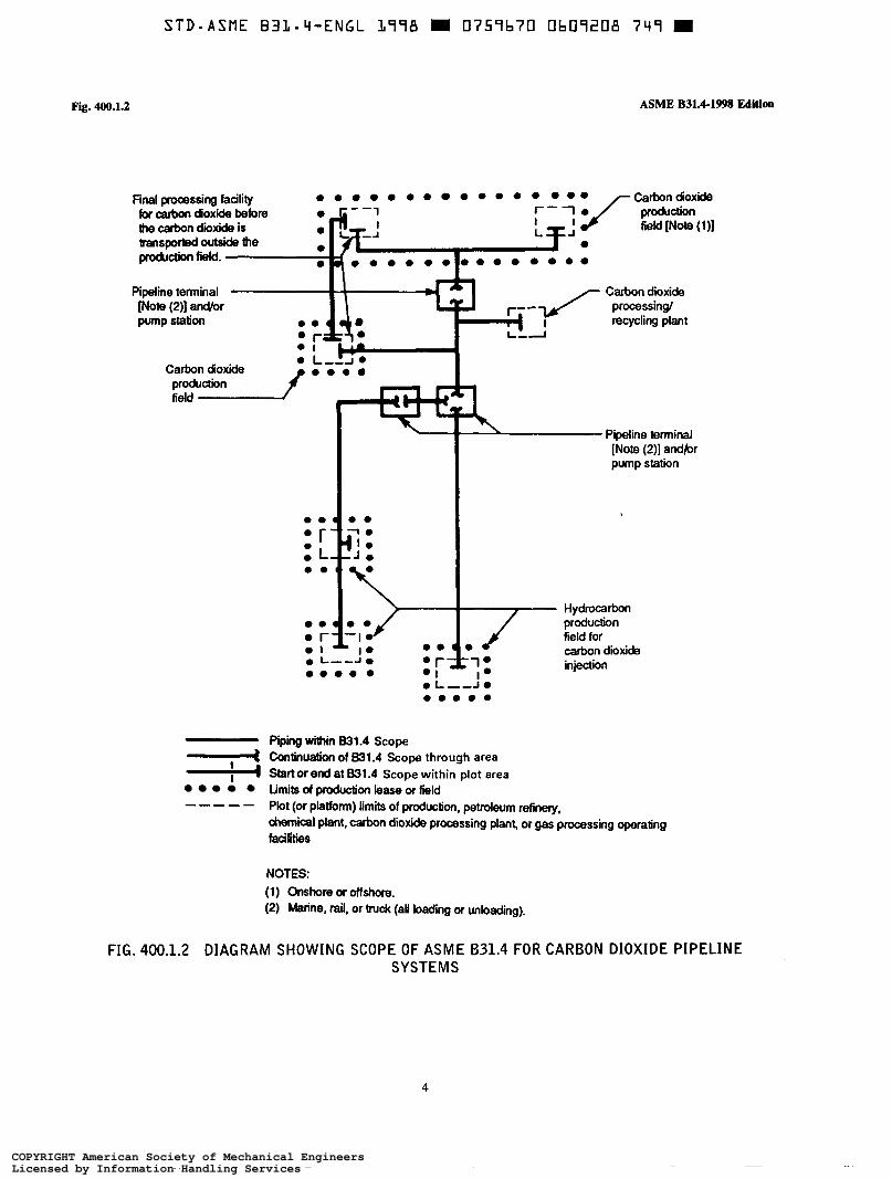
Diagram Showing Scope of ASME B31.4 for Carbon Dioxide Pipeline
Design Conditions and Criteria ................................................... Design Conditions ......................................................... General ................................................................... Pressure ................................................................... Temperature ............................................................... Ambient Influences ......................................................... Dynamic Effects ........................................................... Weight Effects ............................................................. Thermal Expansion and Contraction Loads .................................. Relative Movement of Connected Components ............................... Design Criteria ............................................................ General ................................................................... Pressure-Temperature Ratings for Piping Components ........................ Allowable Stresses and Other Stress Limits ................................. Allowances ................................................................ Fracture Propagation in Carbon Dioxide Pipelines ............................ Pressure Design of Piping Components .................................... Criteria for Pressure Design of Piping Components .......................... Pressure Design of Components ............................................ Straight Pipe ..............................................................
Intersections ...............................................................
Reducers .................................................................. Pressure Design of Other Pressure Containing Components ...................
Design Applications of Piping Components Selection and Limitations ......
Pipeline Systems (See Fig . 400.1.2)
Systems .................................................................
......................................
Curved Segments of Pipe ..................................................
Pressure Design of Flanges .................................................
xi
wii xix
... xi11
1 1 2
3
4
9 9 9 9 9 9 9 9 10 10 10 10 10 11 14 14 14 14 14 14 16 16 24 24 24
25
... 111
COPYRIGHT American Society of Mechanical EngineersLicensed by Information Handling ServicesCOPYRIGHT American Society of Mechanical EngineersLicensed by Information Handling Services

STD-ASME B31-4-ENGL 1998 = 0757b70 Ob09Lôô O20 II
Chapter II
405 405.2 406 406.1 406.2 406.3 406.4 406.5 406.6 407 407.1 407.8 408 408.1 408.3 408.4 408.5 409 Part 4 41 1 41 1.2 412 412.1 414 414.1 418 418.1
Part 5
419 419.1 4 19.5 419.6 4 19.7 420 420.1 42 1 421.1 Part 6 422 422.3
422.6 Figures 404.3.1 (b)(3) 404.3.1(c)( 1)
Design (Cont’d)
Pipe ....................................................................... Metallic Pipe .............................................................. Fittings. Elbows. Bends. and Intersections ................................... Fittings .................................................................... Bends. Miters. and Elbows ................................................. Couplings ................................................................. Reductions ................................................................ Intersections ............................................................... Closures ................................................................... Valves .................................................................... General ................................................................... Special Valves ............................................................. Hanges. Facings. Gaskets. and Bolting ...................................... Flanges .................................................................... Flange Facings ............................................................ Gaskets ................................................................... Bolting .................................................................... Used Piping Components and Equipment .................................... Selection and Limitation of Piping Joints ................................. Welded Joints ............................................................. Butt Welds ................................................................ Flanged Joints ............................................................. General ................................................................... Threaded Joints ............................................................ General ................................................................... Sleeve. Coupled. and Other Patented Joints .................................. General ................................................................... Expansion. Flexibility. Structurai Attachments. Supports. and
Restraints .............................................................. Expansion and Flexibility ................................................... General ................................................................... Flexibility .................................................................
Analysis ................................................................... Loads on Pipe Supporting Elements ......................................... General ................................................................... Design of Pipe Supporting Elements ........................................ Supports. Braces. and Anchors .............................................. Auxiliary and Other Specific Piping ....................................... Design Requirements ....................................................... Instrument and Other Auxiliary Liquid Petroleum or Liquid Anhydrous
Ammonia Piping ......................................................... Pressure Disposal Piping ...................................................
Properties .................................................................
Reinforced Extruded Outlets ................................................ Welding Details for Openings With Complete Encirclement Types of
Reinforcement ........................................................... Welding Details for Openings With Localized Type Reinforcement ...........
25 25 25 25 25 26 26 26 26 27 27 27 27 27 27 21 28 28 28 28 28 28 28 28 28 29 29
29 29 29 29 29 30 33 33 33 33 33 33
33 33
17
19 20
iv
COPYRIGHT American Society of Mechanical EngineersLicensed by Information Handling ServicesCOPYRIGHT American Society of Mechanical EngineersLicensed by Information Handling Services

STD-ASME B31-Li-ENGL 1998 W 0757670 Ob07187 Tb7 m
Chapter II
404.3.1 (c)( 3)
404.3.1(d)(2) 419.6.4(c)
Tables 402.3.1 (a)
402.4.3 404.3.1(c)
Chapter III 423 423.1 423.2 425 425.3 425.4
Table 423.1
Design (Cont’d)
Welding Details for Openings Without Reinforcement Other Than That
Reinforcement of Branch Connections ....................................... Flexibility Factor k and Stress Intensification Factor i ........................
in Header and Branch Walls .............................................
Tabulation of Examples of Allowable Stresses for Reference Use in Piping Systems Within the Scope of This Code ...........................
Weld Joint Factor E ....................................................... Design Criteria for Welded Branch Connections
Materials - General Requirements ......................................... Acceptable Materials and Specifications ..................................... Limitations on Materials .................................................... Materials Applied to Miscellaneous Parts .................................... Gaskets ................................................................... Bolting ....................................................................
............................. Materiais
Material Standards ......................................................... Chapter IV Dimensional Requirements 426 Dimensional Requirements for Standard and Nonstandard Piping
Components .............................................................. 426.1 Standard Piping Components ............................................... 426.2 Nonstandard Piping Components ............................................ 426.3 Threads ................................................................... Table 426.1 Dimensional Standards ..................................................... Chapter V 434 434.1 434.2 434.3 434.4 434.5 434.6 434.7 434.8 434.9 434.10 434.11 434.12 434.13 434.14 434.15 434.16 434.17 434.18 434.19
Construction. Welding. and Assembly Construction ............................................................... General ................................................................... Inspection ................................................................. Right of Way ............................................................. Handling. Hauling. Stringing. and Storing Damage to Fabricated Items and Pipe ....................................... Ditching ................................................................... Bends. Miters. and Elbows ................................................. Welding ................................................................... Tie-In ..................................................................... Installation of Pipe in the Ditch Backfilling ................................................................. Restoration of Right of Way and Cleanup ................................... Special Crossings .......................................................... Inland Coastal Water Construction .......................................... Block and Isolating Valves ................................................. Connections to Main Lines ................................................. Scraper Traps .............................................................. Line Markers .............................................................. Corrosion Control ..........................................................
...................................
............................................
21 23 31
12 15 21
35 35 35 35 35 35
36
39 39 39 39
40
41 41 41 41 41 41 42 42 43 47 47 41 48 48 49 49 50 50 50 50
V
COPYRIGHT American Society of Mechanical EngineersLicensed by Information Handling ServicesCOPYRIGHT American Society of Mechanical EngineersLicensed by Information Handling Services

S T D - A S M E B31.Li-ENGL 1978 0759b70 Ob09170 789
Chapter V Construction. Welding. and Assembly (Cont’d)
434.20 434.21 434.22 434.23 434.24 435 435.1 435.2 435.3 435.4 435.5
Pump Station. Tank Farm. and Terminal Construction ........................ 50 Storage and Working Tankage .............................................. 51 Electrical Installations ...................................................... 52 Liquid Metering ........................................................... 52 Liquid Strainers and Filters ................................................. 52 Assembly of Piping Components ............................................ 53 General ................................................................... 53 Bolting Procedure .......................................................... 53 Pumping Unit Piping ....................................................... 53 Manifolds ................................................................. 53 Auxiliary Liquid Petroleum, Carbon Dioxide, Liquid Anhydrous
Ammonia, or Liquid Alcohol Piping ...................................... 53
Figures 45
434.8.6(a)-(2) Acceptable Butt Welded Joint Design for Unequal Wall Thicknesses ......... 46
Table
434.8.6(a)-(l) Acceptable Butt Welded Joint Design for Equal Wall Thicknesses ............
434.8.6(b) Recommended Attachment Details of Flanges ................................ 48
434.qa) Minimum Cover for Buried Pipelines ....................................... 43
Chapter VI 436 436.1 436.2 436.5 436.6 437 437.1 437.4 437.6 437.7
Chapter VI1 450
450.1 450.2 45 1 451.1 451.2 451.3 45 1.4 45 1.5 45 1.6 45 1.7 451.8 451.9 45 1.10 452 452.1 452.2
Inspection and Testing Inspection ................................................................. 55 General ................................................................... 55 Qualification of Inspectors .................................................. 55 Type and Extent of Examination Required .................................. 55 Repair of Defects .......................................................... 56 Testing .................................................................... 56 General ................................................................... 56 Test Pressure .............................................................. 56 Qualification Tests ......................................................... 57 Records ................................................................... 58
Operation and Maintenance Procedures Operation and Maintenance Procedures Affecting the Safety of Liquid
Transportation Piping Systems ............................................ 59 General ................................................................... 59 Operation and Maintenance Plans and Procedures ............................ 59 Pipeline Operation and Maintenance ........................................ 60 Operating Pressure ......................................................... 60 Communications ........................................................... 60 Markers ................................................................... 60 Right of Way Maintenance ................................................. 60 Patrolling .................................................................. 60 Pipeline Repairs ........................................................... 60 Derating a Pipeline to a Lower Operating Pressure .......................... 64 Valve Maintenance ......................................................... 64 Railroads and Highways Crossing Existing Pipelines ......................... 64 Inland Waters Platform Risers .............................................. 65 Pump Station, Terminal, and Tank Farm Operation and Maintenance ......... 65 General ................................................................... 65 Controls and Protective Equipment .......................................... 65
vi
COPYRIGHT American Society of Mechanical EngineersLicensed by Information Handling ServicesCOPYRIGHT American Society of Mechanical EngineersLicensed by Information Handling Services

STD-ASME B3L.V-ENGL 1798 M 0757b70 Ob07L9L bL5
Chapter VI1 Operation and Maintenance Procedures (Cont’d)
452.3 452.4 452.5 452.6 452.7 453 454 455 456 457
Storage Vessels ............................................................ Storage of Combustible Materials ........................................... Fencing ................................................................... Signs ...................................................................... Prevention of Accidental Ignition ........................................... Corrosion Control .......................................................... Emergency Plan ........................................................... Records ................................................................... Qualifying a Piping System for a Higher Operating Pressure ................. Abandoning a Piping System ...............................................
Figure 451.6.2(a)(7) Parameters Used in Analysis of the Strength of Corroded Areas .............. Chapter VI11 460 46 1 461.1 461.2 461.3 462 462.1 462.2 462.3 463 463.1 463.2 463.3 464 465
Chapter IX A400 A400.1 A400.2 A40 1 A401.1 A40 1.9 A401.10 A401.11 A401.12 A402 A402.3 A402.4 A404 A404.1 A404.3 A405 A405.2 A405.3 A406
Corrosion Control General ................................................................... External Corrosion Control for Buried or Submerged Pipelines ............... New Installations .......................................................... Existing Piping Systems .................................................... Monitoring ................................................................ Internal Corrosion Control .................................................. New Installations .......................................................... Existing Piping Systems .................................................... Monitoring ................................................................ External Corrosion Control for Piping Exposed to Atmosphere ............... New Installations .......................................................... Existing Piping Systems ....................................................
Corrective Measures ........................................................ Records ...................................................................
Monitoring ................................................................
Offshore Liquid Pipeline Systems General Statememts ........................................................ scope ..................................................................... Defi nitions ................................................................. Design Conditions ......................................................... General ................................................................... Installation Design Considerations ...........................................
Hydrostatic Test Design Considerations ...................................... Route Selection Considerations ............................................. Design Criteria ............................................................ Allowable Stresses and Other Stress Limits ................................. Allowances ................................................................ Pressure Design of Components ............................................ Straight Pipe .............................................................. Intersections ............................................................... Pipe ....................................................................... Metallic Pipe .............................................................. Flexible Pipe .............................................................. Fittings. Elbows. Bends. and Intersections
Operational Design Considerations ..........................................
...................................
65 65 65 65 65 66 66 67 67 67
62
69 69 69 71 71 72 72 72 72 73 73 73 73 73 73
75 75 75 76 76 76 77 78 78 79 79 83 83 83 83 83 83 84 84
COPYRIGHT American Society of Mechanical EngineersLicensed by Information Handling ServicesCOPYRIGHT American Society of Mechanical EngineersLicensed by Information Handling Services

STD-ASME B31.Li-ENGL L778 I 0 7 5 9 b 7 0 Ob09192 551 M
Chapter IX Offshore Liquid Pipeline Systems (Cont’d)
A406.2 A406.4 A406.6 A407 A407.1 A408 A408.1 A408.3 A409 A410 A410.1 A410.2 A414 A414.1 A419 A42 1 A423 A423.1 A423.2 A434 A434.2 A434.3 A434.4 A434.6 A434.7 A434.8 A434.11 A434.13 A434.14 A434.15 A434.18 A436 A436.2 A436.5 A437 A437.1 A437.4 A437.6 A437.7 A450
A450.2 A45 1 A45 1.3 A45 1.4 A45 1.5 A45 1.6 A45 1.7 A45 1.8 A45 1.9
Bends. Miters. and Elbows ................................................. 84 Reductions ................................................................ 84 Closures ................................................................... 84 Valves .................................................................... 84 General ................................................................... 84 Flanges, Facings, Gaskets, and Bolting ...................................... 84 Flanges .................................................................... 84 Flange Facings ............................................................ 84 Used Piping Components and Equipment .................................... 84 Other Design Considerations ................................................ 84 Pigs and Internal Inspection Tools .......................................... 84 Special Components ........................................................ 84 Threaded Joints ............................................................ 85 General ................................................................... 85 Expansion and Flexibility .................................................... 85 Design of Pipe-Supporting Elements ........................................ 85 Materials - General Requirements ......................................... 85 Acceptable Materiais and Specifications ..................................... 85 Limitations on Materials .................................................... 85 Construction ............................................................... 85 Inspection ................................................................. 85 Right-of-way .............................................................. 85
Ditching ................................................................... 85
Welding ....................................................... , ........... 86 Backfilling ................................................................. 86
Handling, Hauling, Stringing, and Storing ................................... 85
Bends, Miters, and Elbows ................................................. 86
Special Crossings .......................................................... 86 Offshore Pipeline Construction .............................................. 86 Block and Isolating Valves ................................................. 87 Line Markers .............................................................. 87
Qualification of Inspectors .................................................. 87 Type and Extent of Examination Required .................................. 87 Testing .................................................................... 87 General ................................................................... 87 Test Pressure .............................................................. 87 Qualification Tests ......................................................... 87 Records ................................................................... 88 Operation and Maintenance Procedures Affecting the Safety of Liquid
Transportation Piping Systems ............................................ 88 Operation and Maintenance Plans and Procedures ............................ 88 Pipeline Operation and Maintenance ........................................ 88 Markers ................................................................... 88 Right-of-way Maintenance ................................................. 88 Patrolling .................................................................. 88 Pipeline Repairs ........................................................... 88 Derating a Pipeline to a Lower Operating Pressure .......................... 89 Valve Maintenance ......................................................... 89 Railroads and Highways Crossing Existing Pipelines ......................... 89
Inspection ................................................................. 87
... v111
COPYRIGHT American Society of Mechanical EngineersLicensed by Information Handling ServicesCOPYRIGHT American Society of Mechanical EngineersLicensed by Information Handling Services

Chapter IX
A45 1.10 A451.11 A452
A452.5 A452.7 A454 A460 A46 1 A461.1 A461.3 A463
A463.1
Table A402.3.5 (a)
Appendices A B
Offshore Liquid Pipeline Systems (Cont’d)
Offshore Pipeline Risers .................................................... Inspection ................................................................. Offshore Platform. Pump Station. Terminal. and Tank Farm Operation and
Maintenance .............................................................
Prevention of Accidental Ignition ........................................... Emergency Plan ........................................................... General ................................................................... External Corrosion Control for Offshore Submerged Pipelines ................ New Installations ..........................................................
External Corrosion Control for Offshore Piping Systems Exposed to Atmospheric Conditions ..................................................
New Installations ..........................................................
Fencing ...................................................................
Mon¡ toring ................................................................
Design Factors for Offshore Pipeline Systems ...............................
Referenced Standards ....................................................... Submittal of Technical Inquiries to the B31 Pressure Piping Committee .......
89 89
89 89 89 89 89 90 90 91
91 91
80
93 97
index .................................................................................... 99
COPYRIGHT American Society of Mechanical EngineersLicensed by Information Handling ServicesCOPYRIGHT American Society of Mechanical EngineersLicensed by Information Handling Services

FOREWORD
The need for a national code for pressure piping became increasingly evident from 1915 to 1925. To meet this need the American Engineering Standards Committee (later changed to the American Standards Association) initiated Project B31 in March 1926 at the request of The American Society of Mechanical Engineers, and with that society as sole sponsor. After several years’ work by Sectional Committee B31 and its subcommittees, a first edition was published in 1935 as an American Tentative Standard Code for Pressure Piping.
A revision of the original tentative standard was begun in 1937. Several more years’ effort was given to securing uniformity between sections and to eliminating divergent requirements and discrepancies, as well as to keeping the code abreast of current developments in welding technique, stress computations, and refer- ences to new dimensional and material standards. During this period a new section was added on refrigeration piping, prepared in cooperation with The American Society of Refrigeration Engineers and complementing the American Standard Code for Mechanical Refrigera- tion. This work culminated in the 1942 American Standard Code for Pressure Piping.
Supplements 1 and 2 of the 1942 code, which appeared in 1944 and 1947, respectively, introduced new dimensional and material standards, a new formula for pipe wall thickness, and more comprehensive re- quirements for instrument and control piping. Shortly after the 1942 code was issued, procedures were estab- lished for handling inquiries that require explanation or interpretation of code requirements, and for publish- ing such inquiries and answers in Mechanical Engi- neering for the information of all concerned.
Continuing increases in the severity of service condi- tions, with concurrent developments of new materials and designs equal to meeting these higher requirements, had pointed to the need by 1948 for more extensive changes in the code than could be provided by supple- ments alone. The decision was reached by the American Standards Association and the sponsor to reorganize the Sectional Committee and its several subcommittees, and to invite the various interested bodies to reaffirm their representatives or to designate new ones. Following its reorganization, Sectional Committee B31 made an
intensive review of the 1942 code, and a revised code was approved and published in February 1951 with the designation ASA B31.1-1951, which included:
(a) a general revision and extension of requirements to agree with practices current at the time;
(6) revision of references to existing dimensional standards and material specifications, and the addition of references to new ones; and
(c) clarification of ambiguous or conflicting require- ments.
Supplement No. 1 to B31.1 was approved and pub- lished in 1953 as ASA B31.la-1953. This Supplement and other approved revisions were included in a new edition of B31.1 published in 1955 with the designation
A review by B31 Executive and Sectional Committees in 1955 resulted in a decision to develop and publish industry sections as separate code documents of the American Standard B31 Code for Pressure Piping. ASA B3 1.4- 1959 was the first separate code document for Oil Transportation Piping Systems and superseded that part of Section 3 of the B31.1-1955 code covering Oil Transportation Piping Systems. In 1966 B31.4 was revised to expand coverage on welding, inspection, and testing, and to add new chapters covering construction requirements and operation and maintenance procedures affecting the safety of the piping systems. This revision was published with the designation USAS B31.4-1966, Liquid Petroleum Transportation Piping Systems, since the American Standards Association was reconstituted as the United States of America Standards Institute in 1966. 1
The United States of America Standards Institute, Inc., changed its name, effective October 6, 1969, to the American National Standards Institute, Inc., and USAS B31.4-1966 was redesignated as ANSI B31.4- 1966. The B31 Sectional Committee was redesignated as American National Standards Committee B31 Code for Pressure Piping, and, because of the wide field involved, more than 40 different engineering societies, government bureaus, trade associations, institutes, and the like had one or more representatives on Standards Committee B31, plus a few “Individual Members” to represent general interests. Code activities were
ASA B31.1-1955.
xi
COPYRIGHT American Society of Mechanical EngineersLicensed by Information Handling ServicesCOPYRIGHT American Society of Mechanical EngineersLicensed by Information Handling Services

subdivided according to the scope of the several sec- tions, and general direction of Code activities rested with Standards Committee B31 officers and an Executive Committee whose membership consisted principally of Standards Committee officers and chairmen of the Section and Technical Specialists Committees.
The ANSI B31.4-1966 Code was revised and pub- lished in 1971 with the designation ANSI B31.4-1971.
The ANSI B31.4-1971 Code was revised and pub lished in 1974 with the designation ANSI B31.4-1974.
In December 1978, American National Standards Committee B31 was converted to an ASME Committee with procedures accredited by ANSI. The 1979 revision was approved by ASME and subsequently by ANSI on November 1, 1979, with the designation ANSV
Following publication of the 1979 Edition, the B31.4 Section Committee began work on expanding the scope of the code to cover requirements for the transportation of liquid alcohols. References to existing dimensional standards and material specifications were revised, and new references were added. Other clarifying and edito- rial revisions were made in order to improve the text. These revisions led to the publication of two addenda to B31.4. Addenda ?b? to B31.4 was approved and published in 1981 as ANSVASME B31.4b-1981. Ad- denda ?c? to B31.4 was approved and published in
The 1986 Edition of B31.4 was an inclusion of the two previously published addenda into the 1979 Edition.
ASME B31.4-1979.
1986 as ANSVASME B31.4~-1986.
Following publication of the 1986 Edition, clarifying and editorial revisions were made to improve the text. Additionally, references to existing standards and mate- rial specifications were revised, and new references were added. These revisions led to the publication of an addenda to B3 1.4, which was approved and published in 1987 as ASMWANSI B31.4a-1987.
The 1989 Edition of B31.4 was an inclusion of the previously published addenda into the 1986 Edition.
Following publication of the 1989 Edition, clarifying revisions were made to improve the text. Additionally, references to existing standards and material specifica- tions were revised and updated. These revisions led to the publication of an addenda to B31.4, which was approved and published in 1991 as ASME B31.4a-1991.
The 1992 Edition of B31.4 was an inclusion of the previously published addenda into the 1989 Edition and a revision to valve maintenance. The 1992 Edition was approved by the American National Standards Institute on December 15, 1992, and designated as ASME B31.4-1992 Edition.
The 1998 Edition of B31.4 is an inclusion of the previously published addenda into the 1992 Edition. Also included in this Edition are other revisions (noted by the (98) margin notes) and the addition of Chapter IX, Offshore Liquid Pipeline Systems. This 1998 Edition was approved by the American National Standards Institute on November 11, 1998, and designated as ASME B31.4-1998 Edition.
xii
COPYRIGHT American Society of Mechanical EngineersLicensed by Information Handling ServicesCOPYRIGHT American Society of Mechanical EngineersLicensed by Information Handling Services

ASME CODE FOR PRESSURE PIPING, B31
OFFICERS
L. E. Hayden, Jr., Chuir B. P. Holbrook, Vice Chuir
P. D. Stumpf, Secretary
COMMITTEE PERSONNEL
H. A. Ainsworth, Consultant, Sudbury, Massachusetts R. J. Appleby, Exxon Mobile Upstream Res. Co., Houston, Texas A. E. Beyer, Bechtel Corp., Houston, Texas K. C. Bodenhamer, Williams Energy Services, Tulsa, Oklahoma J. D. Byers, Mobile E & P Technology, Highland Village, Texas J. S. Chin, ANR Pipeline Co., Detroit, Michigan D. M. Fox, Texas Utilities-Pipeline Services, Dallas, Texas J. W. Frey, Reliant Energy Co., Houston, Texas D. R. Frikken, Solutia, Inc., Gerald, Missouri P. H. Gardner, Consultant, Wilmington, Delaware R. R. Hoffmann, Federal Energy Regulatory Commission, Washington, District of Columbia G. A. Jolly, Edward Vogt Valve Co., Jeffersonville, Indiana J. M. Kelly, Willbros Engineers, Inc., Tulsa, Oklahoma W. J. Koves, UOP LLC, Des Plaines, Illinois K. K. Kyser, Frick York International, Waynesboro, Pennsylvania J. E. Meyer, Middough Association, Inc., Cleveland, Ohio E. Michalopoulos, General Engineering and Commercial Co., Kozani, Greece T. J. O’Grady II, Veco Alaska, Inc., Anchorage, Alaska R. G. Payne, ABB-Combustion Engineering, Windsor, Connecticut P. Pertuit III, Black Mesa Pipeline, Inc., Flagstaff, Arizona J. T. Powers, Parsons Energy & Chemicals, Houston, Texas E. H. Rinaca, Virginia Power Co., Glen Allen, Virginia M. J. Rosenfeld, Kiefner & Associates, Inc., Worthington, Ohio R. J. Silvia, Process Engineers and Constructors, Inc., Warwick, Rhode Island W. J. Sperko, Sperko Engineering Services, Inc., Greensboro, North Carolina G. W. Spohn III, Coleman Spohn Corp., Cleveland, Ohio R. W. Straiton, Consultant, Spring, Texas A. L. Watkins, The Perry Nuclear Power Plant, Perry, Ohio R. B. West, State of lowa, Div. of Labor Services, Des Moines, lowa P. A. Bourquin, Ex-Oficio Member, Consultant, Pleasantville, New York P. D. Flenner, Ex-Oflcio Member, Consumers Energy Co, Covert, Michigan R. W. Haupt, Er-Officio Member, Pressure Piping Engineering Associates, Inc., Foster City, California W. B. McGehee, Ex-Officio Member, Consultant, Houston, Texas A. D. Nance, Ex-Oficio Member, A. D. Nance Associates, Inc., Evans, Georgia W. V. Richards, Ex-Oficio Member, Consultant, Lincolnshire, Illinois
B31.4/11 LIQUID AND SLURRY PIPING TRANSPORTATION SYSTEMS SECTION COMMITTEE
A01
K. C. Bodenhamer, Chuir, Williams Energy Services, Tulsa, Oklahoma
xiii
COPYRIGHT American Society of Mechanical EngineersLicensed by Information Handling ServicesCOPYRIGHT American Society of Mechanical EngineersLicensed by Information Handling Services

T. J. O’Grady II, Vice Chuir, Veco Alaska, Inc., Anchorage, Alaska P. Pertuit III, Vice Chair, Black Mesa Pipeline, Inc., Flagstaff, Arizona M. R. Argenziano, Secreiury, ASME International. New York, New York R. S. Barfield, Barfield Engineers, Inc. Humble, Texas L. C. Bennington, Milepost Consulting Services, Inc., Mansfield, Texas A. E. Beyer, ßechtel Corp., Houston, Texas E. E. Cavanagh, Mustang Engineering, Inc.. Houston, Texas J. A. Cox, Dunwoody, Georgia R. D. Deaver, Deatech Consulting Co., Houston, Texas E. P. Hagan, Teppco, Houston, Texas D. B. Kadakia, TD Williamson, Inc., Tulsa, Oklahoma J. F. Kiefner, Kiefner & Associates, Inc., Worthington, Ohio R. D. Lewis, H. Rosen USA, Inc., Houston, Texas A. 1. MacDonald, Consultant, Upland, California M. H. Matheson, American Petrolcum Institute, Washington. Districi of Columbia J. D. Miller, Equilon Enterprises. Houston, Texas W. M. Olson, Gulf Interstate Engineering Co., Houston, Texas S. R. Peterson, Lakehead Pipe Line Co., Bay City, Michigan J. T. Powers, Parsons Energy & Chemicals, Houston, Texas L. J. Schmitz, Phillips Pipe Line Co., Bartlesville, Oklahoma B. C. Shah, Conoco, Houston, Texas R. N. Tennille, Pipeline & Terminal Engineering Consultants, Houston, Texas R. D. Turley, Marathon Ashland Petroleum, LLC, Findlay, Ohio D. R. Turner, Williams Energy Group, Tulsa, Oklahoma L. W. Ulrich, US Department of Transportation, Washington, District of Columbia M. D. Weston, ßechtel Corp., San Francisco, California T. A. Wicklund, Amoco Pipeline Co., Warrenville, Illinois J. E. Zimmerhanzel, Consultant, Houston, Texas C. Zimmerman, NTSB, Washington, District of Columbia
B31 ADMINISTRATIVE COMMITTEE
L. E. Hayden, Jr., Chair, Victaulic Co. of America, Easton, Pennsylvania B. P. Holbrook, Vice Cliuir, D. ß. Riley, Inc., Worcester, Massachusetts P. D. Stumpf, Secrcfury, ASME International, New York, New York K. C. Bodenhamer, Williams Energy Services, Tulsa, Oklahoma J . D. Byers, Mobil E & P Tech, Highland Village, Texas P. D. Flenner, Consumers Energy Co., Covert. Michigan D. M. Fox, Texas Utilities-Pipeline Services, Dallas, Texas D. R. Frikken, Solutia, Inc., Gerald, Missouri P. H. Gardner, Consuliant, Wilmington, Delaware R. R. Hoffmann, Federal Energy Regulatory Commission, Washington, District of Columbia G. A. Jolly, Edward Vogt Valve Co., Jeffersonville. Indiana E. Michalopoulos, General Engineering and Commercial Co.. Kozani, Greece A. D. Nance, A. D. Nance Associates. Inc., Evans, Georgia R. G. Payne, ABß-Coinbusiion Engineering, Windsor, Connecticut G. W. Spohn III, Coleman Spolin Corp., Cleveland, Ohio R. B. West, State of Iowa. Div. of Labor Services. Des Moines, Iowa P. A. Bourquin, Ex-Of;ticio Meniber, Consuliant, Pleasantville, New York R. W. Haupt, Ex-Offïcio Meniber, Pressure Piping Engineering Associates, Inc., Foster City, California W. B. McGehee, Ex-O/Iicio Met~iber, Consultant, Houston. Texas W. V. Richards, Ex-ûficio Meniber. Consultant, Lincolnshire, Illinois
B31 FABRICATION AND EXAMINATION COMMITTEE
P. D. Flenner, Clruir, Consumers Energy Co., Covert, Michigan P. Stumpf, Sccrelury, ASME Internaiional, New York, New York J. P. Ellenberger, WFI International, Inc., Houston, Texas D. J. Fetzner, Arco Alaska, Inc.. Anchorage, Alaska E. Michalopoulos, General Engineering and Coinmercial Co.. Kozani, Greece
xiv
COPYRIGHT American Society of Mechanical EngineersLicensed by Information Handling ServicesCOPYRIGHT American Society of Mechanical EngineersLicensed by Information Handling Services

W. G. Scruggs, E.I. du Pont de Nemours & Co., Wilmington, Delaware R. I. Seals, Consultant, Berkeley, California R. J. Silvia, Process Engineering & Constructors, Inc., Warwick, Rhode Island W. J. Sperko, Sperko Engineering Services, Inc., Greensboro, North Carolina E. F. Summers, Jr., Babcock & Wilcox, Barberton, Ohio
B31 MATERIALS TECHNICAL COMMITTEE
M. L. Nayyar, Chair, Bechtel Power Corp., Frederick, Maryland M. R. Argenziano, Secrefuiy, ASME International, New York, New York M. H. Barnes, Sebesta Blomberg & Associates, Roseville, Minnesota R. P. Deubler, Shaw Groupffronek Co., Englewood, New Jersey C. L. Henley, Black & Veatch, Overland Park, Kansas D. W. Rahoi, CCM 2000, Rockaway, New Jersey R. A. Schmidt, Trinity-Ladish, Russellville, Arkansas
B31 MECHANICAL DESIGN TECHNICAL COMMITTEE
R. W. Haupt, Chuir, Pressure Piping Engineering Associates, Inc., Foster City, California S. J. Rossi, Secreiury, ASME International, New York, New York G. A. Antaki, Westinghouse Savannah River Site, Aiken, South Carolina C. Becht IV, Becht Engineering Co., Liberty Comer, New Jersey J. P. Breen, Pressure Sciences, Inc., Pittsburgh, Pennsylvania J. P. Ellenberger, WFI International, Inc., Houston, Texas D. J. Fetzner, Arco Alaska, Inc.. Anchorage, Alaska J. A. Graziano, Tennessee Valley Authority, Chattanooga, Tennessee J. D. Hart, SSD, Inc., Walnut Creek, California B. P. Holbrook, D. B. Riley, Inc., Worcester, Massachusetts W. J. Koves, UOP LLC, Des Plaines, Illinois G. Mayers, Naval Sea Systems Comm.. Arlington, Virginia T. Q. McCawley, Consultant, Charlotte, North Carolina E. Michalopoulos, General Engineering and Commercial Co., Kozani, Greece J. C. Minichiello, J. C. Minichiello Consulting, Inc., Lake Bluff, Illinois A. D. Nance, A. D. Nance Associates, Inc., Evans, Georgia T. J. O?Grady II, Veco Alaska, Inc., Anchorage, Alaska A. W. Paulin, Paulin Research Group, The Woodlands, Texas P. S. Rampone, Hart Design Group, Greenville, Rhode Island R. A. Robleto, Kellogg Brown & Root, Houston, Texas M. J. Rosenfeld, Kiefner & Associates, Inc., Worthington, Ohio G. Stevick, Berkeley Engineering & Research, Inc.. Berkeley, California Q. N. Truong, Kellogg Brown & Root, Inc., Houston, Texas E. A. Wais, Wais and Associates, Inc., Atlanta, Georgia G. E. Woods, Brown & Root, Houston, Texas E. C. Rodabaugh, Honorury Member, Consultant, Dublin, Ohio
B31 CONFERENCE GROUP
T. A. Bell, Pipeline Safety Engineer, Olympia, Washington G. Bynog, Texas Department of Labor and Standards, Austin, Texas R. A. Coomes, State of Kentucky, Department of HousingíBoiler Section, Frankfort, Kentucky J. W. Greenawalt, Jr., Oklahoma Department of Labor, Oklahoma City, Oklahoma D. H. Hanrath, North Carolina Department of Labor, Raleigh. North Carolina C. J. Harvey, Alabama Public Service Commission, Montgomery. Alabama D. T. Jagger, Ohio Department of Commerce, Reynoldsburg, Ohio M. Kotb, Regie du Batiment du Quebec, Montreal, Quebec, Canada K. T. Lau, Alberta Boilers Safety Association, Edmonton, Alberta, Canada R. G. Marini, New Hampshire Public Utilities Commission, Concord, New Hampshire I. W. Mault, Manitoba Department of Labour, Winnipeg, Manitoba, Canada A. W. Meiring, Fire and Building Boiler and Pressure Vessel Division, Indianapolis, Indiana R. F. Mullaney, Boiler and Pressure Vessel Safety Branch, Vancouver, British Columbia, Canada
xv
COPYRIGHT American Society of Mechanical EngineersLicensed by Information Handling ServicesCOPYRIGHT American Society of Mechanical EngineersLicensed by Information Handling Services

W. A. Owen, North Dakota Public Service Commission, Bismarck, North Dakota P. Sher, State of Connecticut, New Britain, Connecticut M. E. Skarda, State of Arkansas, Department of Labor, Little Rock, Arkansas D. A. Starr, Nebraska Department of Labor, Lincoln, Nebraska D. J. Stursrna, Iowa Utilities Board, Des Moines, Iowa R. P. Sullivan, The National Board of Boiler and Pressure Vessel Inspectors, Columbus, Ohio J. E. Tropprnan, Division of Labodstate of Colorado Boiler Inspections, Denver, Colorado C. H. Walten, National Board of Boiler and Pressure Vessel Inspectors, Columbus, Ohio W. A. West, AC1 Central, Charlottetown, Prince Edward Island, Canada T. F. Wickharn, Rhode Island Department of Labor, Providence, Rhode Island
B31 NATIONAL INTEREST REVIEW GROUP
American Pipe Fitting Association - H. Thielsch American Society of Heating, Refrigeration and Air Conditioning Engineers - H. R. Kornblum Chemical Manufacturers Association - D. R. Frikken Copper Development Association - A. Cohen Ductile Iron Pipe Research Association - T. F. Stroud Edison Electric Institute - R. L. Williams International District Heating Association - G . M. Von Bargen Manufacturers Standardization Society of the Valve and Fittings Industry - R. A. Schmidt National Association of Plumbing-Heating-Cooling Contractors - R. E. White National Certified Pipe Welding Bureau - J. Hansmann National Fire Protection Associaiion - T. C. Lemoff National Fluid Power Association - H. G. Anderson Valve Manufacturers Association - R. A. Handschumacher
O
O
xvi
COPYRIGHT American Society of Mechanical EngineersLicensed by Information Handling ServicesCOPYRIGHT American Society of Mechanical EngineersLicensed by Information Handling Services

STDmASME B31-4-ENGL 1778 0757b70 Ob07200 458 M
INTRODUCTION
The ASME B31 Code for Pressure Piping consists of a number of individually published Sections, each an American National Standard. Hereafter, in this Intro- duction and in the text of this Code Section B31.4, where the word ‘‘Code” is used without specific identi- fication, it means this Code Section.
The Code sets forth engineering requirements deemed necessary for safe design and construction of pressure piping. While safety is the basic consideration, this factor alone will not necessarily govern the final specifi- cations for any piping system. The designer is cautioned that the Code is not a design handbook; it does not do away with the need for the designer or for competent engineering judgment.
To the greatest possible extent, Code requirements for design are stated in terms of basic design principles and formulas. These are supplemented as necessary with specific requirements to assure uniform application of principles and to guide selection and application of piping elements. The Code prohibits designs and prac- tices known to be unsafe and contains warnings where caution, but not prohibition, is warranted.
This Code Section includes: (u) references to acceptable material specifications
and component standards, including dimensional re- quirements and pressure-temperature ratings;
(b) requirements for design of components and as- semblies, including pipe supports;
(c) requirements and data for evaluation and limita- tion of stresses, reactions, and movements associated with pressure, temperature changes, and other forces;
(d) guidance and limitations on the selection and application of materials, components, and joining methods;
(e) requirements for the fabrication, assembly, and erection of piping;
cf) requirements for examination, inspection, and testing of piping; (g) procedures for operation and maintenance that
are essential to public safety; and (h) provisions for protecting pipelines from external
corrosion and internal corrosiotderosion. It is intended that this Edition of Code Section B31.4
and any subsequent Addenda not be retroactive. Unless
agreement is specifically made between contracting parties to use another issue, or the regulatory body having jurisdiction imposes the use of another issue, the latest Edition and Addenda issued at least 6 months prior to the original contract date for the first phase of activity covering a piping system or systems shall be the governing document for all design, materials, fabrication, erection, examination, and testing for the piping until the completion of the work and initial operation.
Users of this Code are cautioned against making use of Code revisions without assurance that they are acceptable to the proper authorities in the jurisdiction where the piping is to be installed.
Code users will note that paragraphs in the Code are not necessarily numbered consecutively. Such dis- continuities result from following a common outline, insofar as practicable, for all Code Sections. In this way, corresponding material is correspondingly numbered in most Code Sections, thus facilitating reference by those who have occasion to use more than one Section.
The Code is under the direction of ASME Committee B31, Code for Pressure Piping, which is organized and operates under procedures of The American Society of Mechanical Engineers which have been accredited by the American National Standards Institute. The Cornmit- tee is a continuing one and keeps all Code Sections current with new developments in materials, construc- tion, and industrial practice. Addenda are issued periodi- cally. New editions are published at intervals of 3 to 5 years.
When no Section of the ASME Code for Pressure Piping specifically covers a piping system, at his discre- tion the user may select any Section determined to be generally applicable. However, it is cautioned that supplementary requirements to the Section chosen may be necessary to provide for a safe piping system for the intended application. Technical limitations of the various Sections, legal requirements, and possible appli- cability of other codes or standards are some of the factors to be considered by the user in determining the applicability of any Section of this Code.
The Committee has established an orderly procedure to consider requests for interpretation and revision of Code requirements. To receive consideration, inquiries
xvii
COPYRIGHT American Society of Mechanical EngineersLicensed by Information Handling ServicesCOPYRIGHT American Society of Mechanical EngineersLicensed by Information Handling Services

STD-ASME B3La'i-ENGL 1978 0759b70 Ob07201 394
must be in writing and must give full particulars (see Mandatory Appendix coveting preparation of technical inquiries).
The approved reply to an inquiry will be sent directly to the inquirer. In addition, the question and reply will be published as part of an Interpretation Supplement issued to the applicable Code Section.
A Case is the prescribed form of reply to an inquiry when study indicates that the Code wording needs clarification or when the reply modifies existing require- ments of the Code or grants permission to use new materials or alternative constructions. Proposed Cases are published in Mechanical Engineering for public review. In addition, the Case will be published as part of a Case Supplement issued to the applicable Code Section.
A Case is normally issued for a limited period, after which it may be renewed, incorporated in the Code, or allowed to expire if there is no indication of further need for the requirements covered by the Case. How-
ever, the provisions of a Case may be used after its expiration or withdrawal, providing the Case was effec- tive on the original contract date or was adopted before completion of the work, and the contracting parties agree to its use.
Materials are listed in the stress tables only when sufficient usage in piping within the scope of the Code has been shown. Materials may be covered by a Case. Requests for listing shall include evidence of satisfactory usage and specific data to permit establishment of allowable stresses, maximum and minimum temperature limits, and other restrictions. Additional criteria can be found in the guidelines for addition of new materials in the ASME Boiler and Pressure Vessel Code, Section II and Section VIU, Division 1, Appendix B. (To develop usage and gain experience, unlisted materials may be used in accordance with para. 423.1.)
Requests for interpretation and suggestions for revi- sion should be addressed to the Secretary, ASME B31 Committee, Three Park Avenue, New York, NY 10016
xviii
COPYRIGHT American Society of Mechanical EngineersLicensed by Information Handling ServicesCOPYRIGHT American Society of Mechanical EngineersLicensed by Information Handling Services

SUMMARY OF CHANGES
Changes given below are identified on the pages by a margin note, (W), placed next to the affected area.
Page Location Change
iii, v-ix Contents
xi¡ Foreword
xviii Introduction
2, 5,6 400.1.1
400.1.2
400.2
9
10
11
14
16
24
25
26
27,28
401.5.6
402.1
402.3.2
404.1.1
404.2.2
404.3.1
404.5.1
404.6
406.1.1
406.4. I
406.6.2
408.1.1
408.3.1
408.4.2
408.5.1
408.5.2
Updated to reflect 98 changes
(1) Next-to-last paragraph revised (2) New last paragraph added
Last paragraph revised
New third paragraph added
Subparagraph (h) revised
(1) acciúental b u d s , breakaway coupling, buckle, cold springing, column buckling, connectors, design life, soil liquefaction, span, and weight coating added
(2) nominal pipe size (NPS) revised (3) offshore deleted
Revised
Second paragraph revised
Subparagraph (e) deleted
Under subparagraph (b), nomenclature for r
Subparagraph (b) revised
Subparagraph (aX2) revised
Subparagraphs (b) and (d) revised
Subparagraph (a) revised
Subparagraphs (a) and (b) revised
Revised
Revised
Subparagraphs (b) and (d) revised
Revised
Subparagraphs (a), (d), and (e) revised
Subparagraph (b) revised
Revised
revised
xix
COPYRIGHT American Society of Mechanical EngineersLicensed by Information Handling ServicesCOPYRIGHT American Society of Mechanical EngineersLicensed by Information Handling Services

Page
27, 28
3 1-33
36, 37
40
42
43
44
49,50
51
52
55
60-64
65
67
69
70,71
Location
414.1
Fig. 419.6.4(c)
Table 423.1
Table 426.1
434.6
Table 434.qa)
434.8.5
434.13.4
434.14
434.15.1
434.18
434.20.7
434.21.2
434.21.3
434.21.5
434.22.1
436.5.1
45 1.6.1
45 1.6.2
451.9
451.10
452.4
455
461.1.1
46 1.1.3
Change
Revised
( i ) On p. 3 1 under Description, fourth entry
(2) Extruded weld tee added (3) Note (4) revised and Note (i i) added
(1) Under Fittings, Valves, and Flanges,
(2) Under Structural Materiais, ASTM A 537
B36.10M, B36.19M, B16.5 through B16.28,
Subparagraph (c) revised
Second and third column headings revised
Subparagraph (a)(4)(d) revised
Subparagraph (c) revised
Revised
( 1 ) Subparagraph (c) deleted (2) Subparagraph (d) redesignated as new (c)
Revised
Revised
Subparagraph (b) revised
Subparagraphs (a) and (b) revised
Revised
Revised
Subparagraphs (b)(9) and (b)( 1 1) revised
(1) First paragraph designated as
(2) Subparagraph (b) added
revised
B16.5 revised
added
B1.l, B1.20.1, and B1.20.3 revised
subparagraph (a)
(1) Subparagraphs (a)(7X (a)(8), and (b)(2)(b) revised
(2) Subparagraphs (b)(7) and (c)( 14) added
Subparagraph (a) revised
Title revised
Revised
Subparagraphs (c) and (e) revised
(i) Subparagraph (c) deleted (2) Subparagraph (d) redesignated as new (c)
Subparagraph (e) revised
xx
COPYRIGHT American Society of Mechanical EngineersLicensed by Information Handling ServicesCOPYRIGHT American Society of Mechanical EngineersLicensed by Information Handling Services

STD-ASME B31.4-ENGL 1978 0759b70 Ob0920Li OT3
Page
70,71
73
75-9 1
93-95
98
102, 103
Location
461.1.5
461.3
465
Chapter IX
Appendix A
B-6
Index
Change
Subparagraph (a) revised
Subparagraph (a) revised
Subparagraph (b) revised
Added
Revised in its entirety
Subparagraph (a) revised
(1) Existing offshore entry deleted (2) Offshore entries to reflect Chapter IX
added
NOTES: (1) The Interpretations to ASME B31.4 issued between January 1, 1994, and December 31, 1997,
(2) After the Interpretations, a separate supplement, Cases No. 4, follows. follow the last page of this Edition as a separate supplement, Interpretations No. 5.
xxi
COPYRIGHT American Society of Mechanical EngineersLicensed by Information Handling ServicesCOPYRIGHT American Society of Mechanical EngineersLicensed by Information Handling Services

ASME B31.4a-2001
CHAPTER I
SCOPE AND DEFINITIONS
400-400.1.1
400 GENERAL STATEMENTS
(a) This Liquid Transportation Systems Code is one of several sections of the ASME Code for Pressure Piping, B31. This Section is published as a separate document for convenience. This Code applies to hydro- carbons, liquid petroleum gas, anhydrous ammonia, alcohols, and ,carbon dioxide. Throughout this Code these systems will be referred to as Liquid Pipeline Systems.
(b) The requirements of this Code are adequate for safety under conditions normally encountered in the operation of liquid pipeline systems. Requirements for all abnormal or unusual conditions are not specifically provided for, nor are all details of engineering and construction prescribed. All work performed within the Scope of this Code shall comply with the safety stan- dards expressed or implied.
(c) The primary purpose of this Code is to establish requirements for safe design, construction, inspection, testing, operation, and maintenance of liquid pipeline systems for protection of the general public and op- erating company personnel as well as for reasonable protection of the piping system against vandalism and accidental damage by others and reasonable protection of the environment.
(d ) This Code is concerned with employee safety to the extent that it is affected by basic design, quality of materials and workmanship, and requirements for construction, inspection, testing, operation, and mainte- nance of liquid pipeline systems. Existing industrial safety regulations pertaining to work areas, safe work practices, and safety devices are not intended to be supplanted by this Code.
( e ) The designer is cautioned that the Code is not a design handbook. The Code does not do away with the need for the engineer or competent engineering judgment. The specific design requirements of the Code usually revolve around a simplified engineering ap- proach to a subject. It is intended that a designer capable of applying more complete and rigorous analysis to special or unusual problems shall have latitude in
0
0
a
0
the development of such designs and the evaluation of complex or combined stresses. In such cases the designer is responsible for demonstrating the validity of his approach.
(f) This Code shall not be retroactive or construed as applying to piping systems installed before date of issuance shown on document title page insofar as design, materials, construction, assembly, inspection, and testing are concerned. It is intended, however, that the provi- sions of this Code shall be applicable within 6 months after date of issuance to the relocation, replacement, and uprating or otherwise changing existing piping systems; and to the operation, maintenance, and corro- sion control of new or existing piping systems. After Code revisions are approved by ASME and ANSI, they may be used by agreement between contracting parties beginning with the date of issuance. Revisions become mandatory or minimum requirements for new installa- tions 6 months after date of issuance except for piping installations or components contracted for or under construction prior to the end of the 6 month period.
(8) The users of this Code are advised that in some areas legislation may establish governmental jurisdiction over the subject matter covered by this Code and are cautioned against making use of revisions that are less restrictive than former requirements without having assurance that they have been accepted by the proper authorities in the jurisdiction where the piping is to be installed. The Department of Transportation, United States of America, rules governing the transportation by pipeline in interstate and foreign commerce of petroleum, petroleum products, and liquids such as anhydrous ammonia or carbon dioxide are prescribed under Part 195 - Transportation of Hazardous Liquids by Pipeline, Title 49 - Transportation, Code of Federal Regulations.
400.1 Scope
400.1.1 This Code prescribes requirements for the 198) design, materiais, construction, assembly, inspection, and testing of piping transporting liquids such as crude
COPYRIGHT American Society of Mechanical EngineersLicensed by Information Handling ServicesCOPYRIGHT American Society of Mechanical EngineersLicensed by Information Handling Services

400.1.1-400.2 ASME B31.4a-2001
oil, condensate, natural gasoline, natural gas liquids, liquefied petroleum gas, carbon dioxide, liquid alcohol, liquid anhydrous ammonia, and liquid petroleum prod- ucts between producers' lease facilities, tank farms, natural gas processing plants, refineries, stations, ammo- nia plants, terminals (marine, rail, and truck), and other delivery and receiving points. (See Fig. 400.1.1 .)
Piping consists of pipe, flanges, bolting, gaskets, valves, relief devices, fittings, and the pressure con- taining parts of other piping components. It also includes hangers and supports, and other equipment items neces- sary to prevent overstressing the pressure containing parts. It does not include support structures such as frames of buildings, stanchions, or foundations, or any equipment such as defined in para. 400.1.2(b).
Requirements for offshore pipelines are found in Chapter IX.
Also included within the scope of this Code are: (a) primary and associated auxiliary liquid petroleum
and liquid anhydrous ammonia piping at pipeline termi- nals (marine, rail, and truck), tank farms, pump stations, pressure reducing stations, and metering stations, includ- ing scraper traps, strainers, and prover loops;
(b) storage and working tanks, including pipe-type storage fabricated from pipe and fittings, and piping interconnecting these facilities;
(c) liquid petroleum and liquid anhydrous ammonia piping located on property which has been set aside for such piping within petroleum refinery, natural gaso- line, gas processing, ammonia, and bulk plants;
(d) those aspects of operation and maintenance of Liquid Pipeline Systems relating to the safety and protection of the general public, operating company personnel, environment, property, and the piping sys- tems [see paras. 400(c) and (d)].
(98) 400.1.2 This Code does not apply to: (a) auxiliary piping, such as water, air, steam, lubri-
cating oil, gas, and fuel; (6 ) pressure vessels, heat exchangers, pumps, meters,
and other such equipment including internal piping and connections for piping except as limited by para. 423.2.4(b);
(c) piping designed for internal pressures: (1) at or below 15 psi ( i bar) gage pressure
regardless of temperature; ( 2 ) above I5 psi ( I bar) gage pressure if design
temperature is below minus 20°F (-30°C) or above 250°F (1 20°C);
(d) casing, tubing, or pipe used in oil wells, wellhead assemblies, oil and gas separators, crude oil production tanks, and other producing facilities;
AO1
(e ) petroleum refinery, natural gasoline, gas pro- cessing, ammonia, carbon dioxide processing, and bulk plant piping, except as covered under para. 400.1.1(c);
(f) gas transmission and distribution piping; (g) the design and fabrication of proprietary items
of equipment, apparatus, or instruments, except as lim- ited by para. 423.2.4(b);
(h) ammonia refrigeration piping systems provided for in ASME B31.5, Refrigeration Piping Code;
( i ) carbon dioxide gathering and field distribution system.
400.2 Definitions
Some of the more common terms relating to piping are defined below.'
accidental loads: any unplanned load or combination of unplanned loads caused by human intervention or natural phenomena.
breakaway coupling: a component installed in the pipeline to allow the pipeline to separate when a predetermined axial load is applied to the coupling.
buckle: a condition where the pipeline has undergone sufficient plastic deformation to cause permanent wrin- kling in the pipe wall or excessive cross-sectional deformation caused by loads acting alone or in combina- tion with hydrostatic pressure.
carbon dioxide: a fluid consisting predominantly of carbon dioxide compressed above its critical pressure and, for the purpose of this Code, shall be considered to be a liquid.
cold springing: deliberate deflection of piping, within its yield strength, to compensate for anticipated thermal expansion.
column buckling: buckling of a beam or pipe under compressive axial load in which loads cause unstable lateral deflection, also referred to as upheaval buckling.
connectors: component, except flanges, used for the purpose of mechanically joining two sections of pipe.
defect: an imperfection of sufficient magnitude to warrant rejection.
' Welding terms which agree with AWS Standard A3.0 are marked with an asterisk (*), For welding terms used in this Code but not shown here, definitions in accordance with AWS A3.0 apply.
2
COPYRIGHT American Society of Mechanical EngineersLicensed by Information Handling ServicesCOPYRIGHT American Society of Mechanical EngineersLicensed by Information Handling Services

ASME B31.4-1998 Edition
A . - - Pipeline terminal," tank farm, and lo r pump stat ion _I L
Fig. 400.1.1
. . . . . . . . . . . . . . Product ion f ie ld +-* r - i r - i ' .
0 0
............... Pipeline terminal " Tank fa rm and lo r pump stat ion ... .- i - 7':
r y i Petroleum ref inery
--L,J L--F= Chemical p lan t
Produc t ion f ie ld T - T e . .*
L ;--5 1 I= Gas processing p lan t A m m o n i a p lan t
m o
Pipeline terminal T a n k fa rm and/or pump station
Pipe t ype storage r - i I r-1 I-- Bu lk p lan t I L L
Process area Petroleum ref inery
Gas processing p lant A m m o n i a p lant Chemical p lant
o
O 0
I
Marine, rail, or t ruck (al l loading o r unloading) Onshore or of fshore Piping within 631.4 scope Cont inuat ion o f 831.4 scope th rough area Start or end a t 831.4 scope w i t h i n p l o t area Limits of p roduc t i on lease o r f ie ld P lo t (o r p la t fo rm) l i m i t s of produc t ion , pe t ro leum refinery, chemical plant, ammonia plant, b u l k plant, or gas processing operat ing faci l i t ies Cor r idor w i t h i n p roper ty o f pe t ro leum refinery, chemical plant, ammonia plant, or gas processing p lan t set aside f o r 831.4 p ip ing Proper ty l ine of pe t ro leum refinery, chemical plant, ammon ia plant, ~ e s processing plant, o r bulk p lan t
FIG. 400.1.1 DIAGRAM SHOWING SCOPE OF ASME 831.4 EXCLUDING CARBON DIOXIDE PIPELINE SYSTEMS (SEE FIG. 400.1.2)
3
COPYRIGHT American Society of Mechanical EngineersLicensed by Information Handling ServicesCOPYRIGHT American Society of Mechanical EngineersLicensed by Information Handling Services
S T D * A S M E B31.L i -ENGL 1998 U 0759b70 Ob09208 7q9
. . O . . e . . . . . . 0 . . Carbon dioxide produaion ñeid [Note (i)]
Final processing faUlity tor cahon dioxide before Um carbon dioxide is transpotted outside the production fieid.
Pipeline terminal - - Carbon dioxide [Note (211 W o r pump station
. I . L-K I
Carbon dioxide
Fig. 400.1.2 ASME B31.4-199% Edition
Pipeline terminal [Note (31 and/or pump station
Hydrocarbon production field for carbon dioxide
,l injection I.
piping within 831.4 Scope Continuaí¡on of 831.4 Scope through area
4 Startorendat 831.4 Scope within plot area t l ,
timitsofproâucüonleaseorfieM ----- Plot (or plabrm) limits of production, petroleum refmery, diemical piant, carbon dioxide processing plant, or gas processing operating faUlitieS
NOTES (1) Onshore or off shore. (2) Marine, rail, or bud< (all loading or unloading).
FIG. 400.1.2 DIAGRAM SHOWING SCOPE OF ASME 631.4 FOR CARBON DIOXIDE PIPELINE SYSTEMS
4
COPYRIGHT American Society of Mechanical EngineersLicensed by Information Handling ServicesCOPYRIGHT American Society of Mechanical EngineersLicensed by Information Handling Services

S T D ASHE 831 4-ENGL
ASME B31.4-1998 Edi th
1998 IIP 0759b70 Ob09207 h85
design life: a period of time used in design calcula- tions, selected for the purpose of verifying that a replaceable or permanent component is suitable for the anticipated period of service. Design life does not pertain to the life of the pipeline system because a properly maintained and protected pipeline system can provide liquid transportation service indèfinitely.
engineering design: detailed design developed from operating requirements and conforming to Code require- ments, including all necessary drawings and specifica- tions, governing a piping installation.
general corrosion: uniform or gradually varying loss of wall thickness over an area.
girth weld: ing pipe or components.
a complete circumferential butt weld join-
imperfection: a discontinuity or irregularity which is detected by inspection.
internal design pressure: internal pressure used in calculations or analysis for pressure design of a piping component (see para. 401.2.2).
liquefied petroleum gas(es) (LPG): liquid petroleum composed predominantly of the following hydrocarbons, either by themselves or as mixtures: butane (normal butane or isobutane), butylene (including isomers), pro- pane, propylene, and ethane.
liquid alcohol: any of a group of organic compounds containing only hydrogen, carbon, and one or more hydroxyl radicals which will remain liquid in a moving stream in a pipeline.
liquid anhydrous ammonia: a compound formed by the combination of the two gaseous elements, nitrogen and hydrogen, in the proportion of one part of nitrogen to three parts of hydrogen, by volume, compressed to a liquid state.
maximum steady state operating pressure: maximum pressure (sum of static head pressure, pressure required to overcome friction losses, and any back pressure) at any point in a piping system when the system is operating under steady state conditions.
miter: two or more straight sections of pipe matched and joined on a line bisecting the angle of junction so as to produce a change in direction.
480.2
nominal pipe size (NPS): see ASME B36.10M p. 1 for definition.
operating company: owner or agent currently responsi- ble for the design, construction, inspection, testing, operation, and maintenance of the piping system.
petroleum: crude oil, condensate, natural gasoline, nat- ural gas liquids, liquefied petroleum gas. and liquid petroleum products.
pipe: a tube, usually cylindrical, used for conveying a fluid or transmitting fluid pressure, normally designated “pipe” in the applicable specification. It also includes any similar component designated as “tubing” used for the same purpose. Types of pipe, according to the method of manufacture, are defined as follows.
(a) electric resistance welded pipe: pipe produced in individual lengths or in continuous lengths from coiled skelp, having a longitudinal or spiral butt joint wherein coalescence is produced by the heat obtained from resistance of the pipe to the flow of electric current in a circuit of which the pipe is a part, and by the application of pressure.
(6) furnace lap welded pipe: pipe having a longitudi- nal lap joint made by the forge welding process wherein coalescence is produced by heating the preformed tube to welding temperature and passing it over a mandrel located between two welding rolls which compress and weld the overlapping edges.
(c) furnace butt welded pipe ( I ) furnace butt welded pipe, bell welded: pipe
produced in individual lengths from cut-length skelp, having its longitudinal butt joint forge welded by the mechanical pressure developed in drawing the furnace heated skelp through a cone-shaped die (commonly known as the “welding bell”) which serves as a combined forming and welding die.
(2) furnace butt welded pipe, continuous welded: pipe produced in continuous lengths from coiled skelp and subsequently cut into individual lengths, having its longitudinal butt joint forge welded by the mechanical pressure developed in rolling the hot formed skelp through a set of round pass welding rolls.
(d) electricfusion welded pipe: pipe having a longitu- dinal or spiral butt joint wherein coalescence is produced in the preformed tube by manual or automatic electric arc welding. The weld may be single or double and may be made with or without the use of filler metal. Spiral welded pipe is also made by the electric fusion welded process with either a lap joint or a lock- seam joint.
5
COPYRIGHT American Society of Mechanical EngineersLicensed by Information Handling ServicesCOPYRIGHT American Society of Mechanical EngineersLicensed by Information Handling Services

STD*ASME B31-9-ENGL 1998 0757b70 Ob0721U 3T7
400.2
(e) electric f i s h welded pipe: pipe having a longitu- dinal butt joint wherein coalescence is produced simulta- neously over the entire area of abutting surfaces by the heat obtained from resistance to the flow of electric current between the two surfaces, and by the application of pressure after heating is substantially completed. Flashing and upsetting are accompanied by expulsion of metal from the joint.
(f) double submerged arc welded pipe: pipe having a longitudinal or spiral butt joint produced by at least two passes, one of which is on the inside of the pipe. Coalescence is produced by heating with an electric arc or arcs between the bare metal electrode or electrodes and the work. The welding is shielded by a blanket of granular, fusible material on the work. Pressure is not used and filler metal for the inside and outside welds is obtained from the electrode or electrodes.
( g ) seamless pipe: pipe produced by piercing a billet followed by rolling or drawing, or both.
(h) electric induction welded pipe: pipe produced in individual lengths or in continuous lengths from coiled skelp having a longitudinal or spiral butt joint wherein coalescence is produced by the heat obtained from resistance of the pipe to induced electric current, and by application of pressure.
pipe nominal wall thickness: the wall thickness listed in applicable pipe specifications or dimensional stan- dards included in this Code by reference. The listed wall thickness dimension is subject to tolerances as given in the specification or standard.
pipe supporting elements: pipe supporting elements consist of fixtures and structural attachments as follows.
(a) fitures: fixtures include elements which transfer the load from the pipe or structural attachment to the supporting structure or equipment. They include hanging type fixtures such as hanger rods, spring hangers, sway braces, counterweights, turnbuckles, struts, chains, guides and anchors, and bearing type fixtures such as saddles, bases, rollers, brackets, and sliding supports.
(b) structural attachments: structural attachments in- clude elements which are welded, bolted, or clamped to the pipe, such as clips, lugs, rings, clamps, clevises, straps, and skirts.
pressure: unless otherwise stated, pressure is ex- pressed in pounds per square inch (bar) above atmo- spheric pressure, ¡.e., gage pressure as abbreviated psig (bar).
shall: a provision is mandatory.
?shall? or ?shall not? is used to indicate that
ASME B31.4-1998 Edition
should: ?should? or ?it is recommended? is used to indicate that a provision is not mandatory but recom- mended as good practice.
soil liquefaction: a soil condition, typically caused by dynamic cyclic loading (e.g., earthquake, waves) where the effective shear strength of the soil is reduced such that the soil exhibits the properties of a liquid.
span:
temperatures: are expressed in degrees Fahrenheit (OF) unless otherwise stated.
a section of pipe that is unsupported
weight coating: any coating applied to the pipeline for the purpose of increasing the pipeline specific gravity.
arc weiáing*: a group of welding processes wherein coalescence is produced by heating with an electric arc or arcs, with or without the application of pressure and with or without the use of filler metal.
automatic welding*: welding with equipment which performs the entire welding operation without constant observation and adjustment of the controls by an opera- tor. The equipment may or may not perform the loading and unloading of the work.
jìllet weld*: a weld of approximately triangular cross section joining two surfaces approximately at right angles to each other in a lap joint, tee joint, or corner joint.
full jìllet weld*: the thickness of the thinner member joined.
gas welding*: a group of welding processes wherein coalescence is produced by heating with a gas flame or flames, with or without the application of pressure, and with or without the use of filler metal.
gas metal arc welding*: an arc welding process wherein coalescence is produced by heating with an electric arc between a filler metal (consumable) electrode and the work. Shielding is obtained from a gas, a gas mixture (which may contain an inert gas), or a mixture of a gas and a flux. (This process has sometimes been called Mig welding or CO2 welding.)
gas tungsten arc welding*: an arc welding process wherein coalescence is produced by heating with an electric arc between a single tungsten (nonconsumable) electrode and the work. Shielding is obtained from a gas or gas mixture (which may contain an inert gas). Pressure may or may not be used and filler metal may
a fillet weld whose size is equal to
6
COPYRIGHT American Society of Mechanical EngineersLicensed by Information Handling ServicesCOPYRIGHT American Society of Mechanical EngineersLicensed by Information Handling Services

STD-ASME B31-Y-ENGL 1998 0759b70 Ob072L1 233
or may not be used. (This process has sometimes been called Tig welding.)
semiautomatic arc welding*: arc welding with equip ment which controls only the filler metal feed. The advance of the welding is manually controlled.
shielded metal arc welding*: an arc welding process wherein coalescence is produced by heating with an electric arc between a covered metal electrode and the work. Shielding is obtained from decomposition of the electrode covering. Pressure is not used and filler metal is obtained from the electrode.
submerged arc welding*: an arc welding process wherein coalescence is produced by heating with an electric arc or arcs between a bare metal electrode or electrodes and the work. The welding is shielded by a blanket of granular, fusible material on the work. Pressure is not used, and filler metal is obtained from
400.2
the electrode and sometimes from a supplementary welding rod. tack weld*: a weld made to hold parts of a weldment in proper alignment until subsequent welds are made
weld*: a localized coalescence of metal wherein co- alescence is produced by heating to suitable tempera- tures, with or without the application of pressure, and with or without the use of filler metal. The filler metal shall have a melting point approximately the same as the base metal.
welder*: one who is capable of performing a manual or semiautomatic welding operation.
welding operator*: one who operates machine or auto- matic welding equipment.
welding procedures*: the detailed methods and prac- tices including joint welding procedures involved in the production of a weldment.
7
COPYRIGHT American Society of Mechanical EngineersLicensed by Information Handling ServicesCOPYRIGHT American Society of Mechanical EngineersLicensed by Information Handling Services

ASME B31.4-1998 Edition
CHAPTER II DESIGN
40141.6
PART 1 CONDITIONS AND CRITERIA
to specifications approved for use under this Code may not have properties suitable for the lower portion of the temperature band covered by this Code. Engineers are cautioned to give attention to the low temperature properties of the materials used for facilities to be exposed to unusually low ground temperatures, low atmospheric temperatures, or transient operating condi- tiens.
401.4 Ambient Influences
401 DESIGN CONDITIONS
401.1 General
Paragraph 401 defines the pressures, temperatures, and various forces applicable to the design of piping systems within the scope of this Code. It also takes into account considerations that shall be given to ambient and mechanical influences and various loadings.
401.2 Pressure
401.2.2 Internai Design Pressure. The piping com- ponent at any point in the piping system shall be designed for an internal design pressure which shall not be less than the maximum steady state operating pressure at that point, or less than the static head pressure at that point with the line in a static condition. The maximum steady state operating pressure shall be the sum of the static head pressure, pressure required to overcome friction losses, and any required back pressure. Credit may be given for hydrostatic external pressure, in the appropriate manner, in modifying the internal design pressure for use in calculations involving the pressure design of piping components (see para. 404.1.3). Pressure rise above maximum steady state operating pressure due to surges and other variations from normal operations is allowed in accordance with para. 402.2.4.
401.2.3 External Design Pressure. The piping com- ponent shall be designed to withstand the maximum possible differential between external and internal pres- sures to which the component will be exposed.
401.3 Temperature
401.3.1 Design Temperature. The design tempera- ture is the metal temperature expected in normal opera- tion. It is not necessary to vary the design stress for metal temperatures between -20°F (-30°C) and 250°F (120°C). However, some of the materials conforming
401.4.2 Fluid Expansion Effects. Provision shall be made in the design either to withstand or to relieve increased pressure caused by the heating of static fluid in a piping component.
401.5 Dynamic Effects
401.5.1 Impact. Impact forces caused by either exter- nal or internal conditions shall be considered in the design of piping systems.
401.5.2 Wind. The effect of wind loading shall be provided for in the design of suspended piping.
401.5.3 Earthquake. Consideration in the design shall be given to piping systems located in regions where earthquakes are known to occur.
401.5.4 Vibration. Stress resulting from vibration or resonance shall be considered and provided for in accordance with sound engineering practice.
401.5.5 Subsidence. Consideration in the design shall be given to piping systems located in regions where subsidence is known to occur.
401.5.6 Waves and Currents. The effects of waves 198) and currents shall be provided for in the design of pipelines across waterways.
401.6 Weight Effects
The following weight effects combined with loads and forces from other causes shall be taken into account in the design of piping that is exposed, suspended, or not supported continuously.
9
COPYRIGHT American Society of Mechanical EngineersLicensed by Information Handling ServicesCOPYRIGHT American Society of Mechanical EngineersLicensed by Information Handling Services

401.6.1402.2.5
401.6.1 Live Loads. Live loads include the weight of the liquid transported and any other extraneous materials such as ice or snow that adhere to the pipe. The impact of wind, waves, and currents are also considered live loads.
401.6.2 Dead Loads. Dead loads include the weight of the pipe, components, coating, backfill, and unsup- ported attachments to the piping.
401.7 Thermal Expansion and Contraction Loads
Provisions shall be made for the effects of thermal expansion and contraction in all piping systems.
401.8 Relative Movement of Connected Components
The effect of relative movement of connected compo- nents shall be taken into account in design of piping and pipe supporting elements.
402 DESIGN CRITERIA
(98) 402.1 General
Paragraph 402 pertains to ratings, stress criteria, design allowances, and minimum design values, and formulates the permissible variations to these factors used in the design of piping systems within the scope of this Code.
The design requirements of this Code are adequate for public safety under conditions usually encountered in piping systems within the scope of this Code, includ- ing lines within villages, towns, cities, and industrial areas. However, the design engineer shall provide rea- sonable protection to prevent damage to the pipeline from unusual external conditions which may be encoun- tered in river crossings, inland coastal water areas, bridges, areas of heavy traffic, long self-supported spans, unstable ground, vibration, weight of special attach- ments, or forces resulting from abnormal thermal condi- tions. Some of the protective measures which the design engineer may provide are encasing with steel pipe of larger diameter, adding concrete protective coating, increasing the wall thickness, lowering the line to a greater depth, or indicating the presence of the line with additional markers.
402.2 Pressure-Temperature Ratings for Piping
402.2.1 Components Having Specific Ratings. Within the metal temperature limits of -20°F (-30°C) to 250°F (120"C), pressure ratings for components shall
Components
ASME 631.4-1998 Edition
conform to those stated for 100°F (40°C) in material standards listed in Table 423.1. The nonmetallic trim, packing, seals, and gaskets shall be made of materials which are not injuriously affected by the fluid in the piping system and shall be capable of withstanding the pressures and temperatures to which they will be sub- jected in service. Low temperatures due to pressure reduction situations, such as blow downs and other events, shall be considered when designing carbon dioxide pipelines.
402.2.2 Ratings - Components Not Having Spe- cific Ratings. Piping components not having established pressure ratings may be qualified for use as specified in paras. 404.7 and 423.1(b).
402.2.3 Normal Operating Conditions. For normal operation the maximum steady state operating pressure shall not exceed the internal design pressure and pressure ratings for the components used.
402.2.4 Ratings - Allowance for Variations From Normal Operations. Surge pressures in a liquid pipeline are produced by a change in the velocity of the moving stream that results from shutting down of a pump station or pumping unit, closing of a valve, or blockage of the moving stream.
Surge pressure attenuates (decreases in intensity) as it moves away from its point of origin.
Surge calculations shall be made, and adequate con- trols and protective equipment shall be provided, so that the level of pressure rise due to surges and other variations from normal operations shall not exceed the internal design pressure at any point in the piping system and equipment by more than 10%.
402.2.5 Ratings - Considerations for Different Pressure Conditions. When two lines that operate at different pressure conditions are connected, the valve segregating the two lines shall be rated for the more severe service condition. When a line is connected to a piece of equipment which operates at a higher pressure condition than that of the line, the valve segregating the line from the equipment shall be rated for at least the operating condition of the equipment. The piping between the more severe conditions and the valve shall be designed to withstand the operating conditions of the equipment or piping to which it is connected.
10
COPYRIGHT American Society of Mechanical EngineersLicensed by Information Handling ServicesCOPYRIGHT American Society of Mechanical EngineersLicensed by Information Handling Services

ASME B31.4a-2001 402.3402.3.3
402.3 Allowable Stresses and Other Stress Limits
402.3.1 Allowable Stress Values (a) The allowable stress value S to be used for
design calculations in para. 404.1.2 for new pipe of known specification shall be established as follows:
S = 0.72 X E X specified minimum yield strength of the pipe, psi (MPa)
where 0.72 = design factor based on nominal wall thick-
ness. In setting design factor, due consider- ation has been given to and allowance has been made for the underthickness tolerance and maximum allowable depth of imperfec- tions provided for in the specifications ap- proved by the Code.
E = weld joint factor (see para. 402.4.3 and Table 402.3.3)
Table 402.3.1(a) is a tabulation of examples of allowable stresses for reference use in transportation piping systems within the scope of this Code.
(b ) The allowable stress value S to be used for design calculations in para. 404.1.2 for used (reclaimed) pipe of known specification shall be in accordance with (a) above and limitations in para. 405.2.1(b).
(c) The allowable stress value S to be used for design calculations in para. 404.1.2 for new or used (reclaimed) pipe of unknown or ASTM A 120 specifica- tion shall be established in accordance with the follow- ing and limitations in para. 405.2.1(c).
O
S = 0.72 X E X minimum yield strength of the pipe, psi (MPa) [24,000 psi (165 MPa)] or yield strength determined in accordance with paras. 437.6.6 and 437.6.71
0.72 = design factor based on nominal wall thick- ness. In setting design factor, due consider- ation has been given to and allowance has been made for the underthickness tolerance and maximum allowable depth of imperfec- tions provided for in the specifications ap- proved by the Code.
E = weld joint factor (see Table 402.4.3) (d ) The allowable stress value S to be used for
design calculations in para. 404.1.2 for pipe which has been cold worked in order to meet the specified mini- mum yield strength and is subsequently heated to 600°F (300°C) or higher (welding expected) shall be 75% of a
the applicable allowable stress value as determined by para. 402.3.1(a), (b), or (c).
(e ) Allowable stress values in shear shall not exceed 45% of the specified minimum yield strength of the pipe, and allowable stress values in bearing shall not exceed 90% of the specified minimum yield strength of the pipe.
(f) Allowable tensile and compressive stress values for materials used in structural supports and restraints shall not exceed 66% of the specified minimum yield strength. Allowable stress values in shear and bearing shall not exceed 45% and 90% of the specified minimum yield strength, respectively. Steel materials of unknown specifications may be used for structural supports and restraints, provided a yield strength of 24,000 psi (165 MPa) or less is used.
(g) In no case where the Code refers to the specified minimum value of a physical property shall a higher value of the property be used in establishing the allow- able stress value.
402.3.2 Limits of Calculated Stresses Due to (98) Sustained Loads and Thermal Expansion
(a) Internal Pressure Stresses. The calculated stresses due to internal pressure shall not exceed the applicable allowable stress value S determined by para. 402.3.1 (a), (b), (c), or (d) except as permitted by other subpara- graphs of para. 402.3.
(b) External Pressure Stresses. Stresses due to exter- nal pressure shall be considered safe when the wall thickness of the piping components meets the require- ments of paras. 403 and 404.
(c) Allowable Expansion Stresses. The allowable stress values for the equivalent tensile stress in para. 419.6.4(b) for restrained lines shall not exceed 90% of the specified minimum yield strength of the pipe. The allowable stress range S A in para. 419.6.4(c) for unrestrained lines shall not exceed 72% of the specified minimum yield strength of the pipe.
(d) Additive Longitudinal Stresses. The sum of the longitudinal stresses due to pressure, weight, and other sustained external loadings [see para. 419.6.4(c)] shall not exceed 75% of the allowable stress value specified for S A in (c) above.
402.3.3 Limits of Calculated Stresses Due to Occasional Loads
(a) Operation. The sum of the longitudinal stresses produced by pressure, live and dead loads, and those produced by occasional loads, such as wind or earth- quake, shall not exceed 80% of the specified minimum
11
COPYRIGHT American Society of Mechanical EngineersLicensed by Information Handling ServicesCOPYRIGHT American Society of Mechanical EngineersLicensed by Information Handling Services
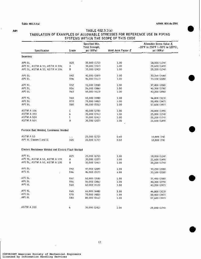
Table 402.3.1(a) ASME B31.4a-2001
A01 TABLE 402.3.1 (a> TABULATION OF EXAMPLES OF ALLOWABLE STRESSES FOR REFERENCE USE I N PIPING
SYSTEMS WITHIN THE SCOPE OF THIS CODE Specified Min. Allowable Stress Value S, Yield Strength, -20°F to 250°F (-30°C to 12O"C),
Specification Grade psi (MPa) Weld Joint Factor E psi (MPa)
Seamless
A P I 5 L A25 25,000 (172) API 5L, ASTM A 53, ASTM A 106 30,000 (207) API 5L, ASTM A 53, ASTM A 106 35,000 (241)
A 6
A P I 5L A P I 5L
A P I 5 L A P I 5 L A P I 5 L
A P I 5 L A P I 5L A P I 5L
ASTM A 106 ASTM A 333 ASTM A 524 ACTM A 524
Furnace Butt Welded, Continuous Welded
ASTM A 53 A P I 5L Classes I and II
X42 42,000 (289) X46 46,000 (317)
X52 52,000 (358) X56 56,000 (386) X60 60,000 (413)
X65 65,000 (448) X70 70,000 (482) X80 80,000 (551)
C 40,000 (278) 6 35,000 (241) I 35,000 (241) H 30,000 (207)
. . . 25,000 (172) A25 25,000 (172)
Electric Resistance Welded and Electric Flash Welded
A P I 5L A25 25,000 (172) A P I 5L, ASTM A 53, ASTM A 135 30,000 (207) A P I 5L, ASTM A 53, ASTM A 135 35,000 (241)
A B
A P I 5L A P I 5L
A P I 5 L A P I 5L A P I 5L
A P I 5L A P I 5L A P I 5L
X42 42,000 (289) X46 46,000 (317)
X52 52,000 (358) X56 56,000 (386) X60 60,000 (413)
X65 65,000 (448) X70 70,000 (482) X80 80,000 (551)
ASTM A 333 6 35,000 (241)
1.00 1.00 1.00
1.00 1.00
1.00 1.00 1.00
1.00 1.00 1.00
1.00 1.00 1.00 1.00
0.60 0.60
1.00 1.00 1.00
1.00 1.00
1.00 1.00 1.00
1.00 1.00 1.00
1.00
18,000 (124) 21,600 (149) 25,200 (174)
30,250 (208) 33,100 (228)
37,450 (258) 40,300 (278) 43,200 (298)
46,800 (323) 50,400 (347) 57,600 (397)
28,800 (199) 25,000 (174) 25,200 (174) 21,600 (149)
10,800 (74) 10,800 (74)
18,000 (124) 21,600 (149) 25,200 (174)
30,250 (208) 33,100 (228)
37,450 (258) 40,300 (279) 43,200 (297)
46,800 (323) 50,400 (347) 57,600 (397)
25,000 (174)
12
COPYRIGHT American Society of Mechanical EngineersLicensed by Information Handling ServicesCOPYRIGHT American Society of Mechanical EngineersLicensed by Information Handling Services

Table 402.3.1(a) ASME B31.4a-2001
TABLE 402.3.1(a) (CONT'D) A01
TABULATION OF EXAMPLES OF ALLOWABLE STRESSES FOR REFERENCE USE I N PIPING SYSTEMS WITHIN THE SCOPE OF THIS CODE
Specified Min. Yield Strength,
Allowable Stress Value S, -20°F to 250°F (-30°C to 120"C),
Specification Grade psi ( M Pa) Weld Joint Factor E psi (MPa)
Electric Fusion Welded
ASTM A 134 ASTM A 139 ASTM A 139
ASTM A 671 ASTM A 671 ASTM A 672 ASTM A 672
Submerged Arc Welded
API 5L API 5L
API 5L API 5L
API 5L API 5 L API 5L
API 5L API 5L API 5L
ASTM A 381 ASTM A 381 ASTM A 381 ASTM A 381
ASTM A 381 ASTM A 381 ASTM A 381 ASTM A 381
. . . A B
. . .
. . .
. . .
. . .
A B
X42 X46
X52 X56 X60
X65 X70 X80
Y35 Y42 Y46 Y48
Y50 Y52 Y60 Y65
. . . 30,000 (207) 35,000 (241)
Note (1) Note (1) Note (1) Note (1)
30,000 (207) 35,000 (241)
42,000 (289) 46,000 (317)
52,000 (358) 56,000 (386) 60,000 (413)
65,000 (448) 70,000 (482) 80,000 (551)
35,000 (241) 42,000 (290) 46,000 (317) 48,000 (331)
50,000 (345) 52,000 (358) 60,000 (413) 65,000 (448)
0.80 0.80 0.80
1.00 [Notes ( 2 ) , ( 3 ) l 0.70 [Note (411
1.00 [Notes (2), ( 3 ) l 0.80 [Note (4 ) l
1.00 1.00
1.00 1.00
1.00 1.00 1.00
1.00 1.00 1.00
1.00 1.00 1.00 1.00
1.00 1.00 1.00 1.00
17,300 (119) 20,150 (139)
. . .
. . .
21,600 (149) 25,200 (174)
30,250 (208) 33,100 (228)
37,450 (258) 40,300 (278) 43,200 (298)
46,800 (323) 50,400 (347) 57,600 (397)
25,200 (174) 30,250 (209) 33,100 ( 2 2 8 ) 34,550 (238)
36,000 (248) 37,450 (258) 43,200 (298) 46,800 (323)
GENERAL NOTES: (a) Allowable stress values S shown in this Table are equal to 0.72E (weld joint factor) X specified minimum yield strength of the pipe. (b) Allowable stress values shown are for new pipe of known specification. Allowble stress values for new pipe of unknown specification, ASTM
A 120 specification, or used (reclaimed) pipe shall be determined in accordance with para. 402.3.1. (c) For some Code computations, particularly with regard to branch connections [see para. 404.3.1(d)(3)1 and expansion, flexibility, structural
attachments, supports, and restraints (Chapter II, Part 5), the weld joint factor E need not be considered. (d) For specified minimum yield strength of other grades in approved specifications, refer to that particular specification. (e) Allowable stress value for cold worked pipe subsequently heated to 600°F (300°C) or higher (welding excepted) shall be 75% of the value
listed in Table. ( f ) Definitions for the various types of pipe are given in para. 400.2. (g) Metric stress levels are given in MPa (1 megapascal = 1 million pascals).
NOTES: (1) See applicable plate specification for yield point and refer to para. 402.3.1 for calculation of S. (2 ) Factor applies for Classes 12, 22, 32, 42, and 52 only. (3 ) Radiography must be performed after heat treatment. (4 ) Factor applies for Classes 13, 23, 33, 43, and 53 only.
13
COPYRIGHT American Society of Mechanical EngineersLicensed by Information Handling ServicesCOPYRIGHT American Society of Mechanical EngineersLicensed by Information Handling Services

402.3.3-404.1.1 ASME B31.4a-2001
yield strength of the pipe. It is not necessary to consider wind and earthquake as occurring concurrently.
(6) Test. Stresses due to test conditions are not subject to the limitations of para. 402.3. It is not necessary to consider other occasional loads, such as wind and earthquake, as occurring concurrently with the live, dead, and test loads existing at the time of test.
402.4 Allowances
402.4.1 Corrosion. A wall thickness allowance for corrosion is not required if pipe and components are protected against corrosion in accordance with the requirements and procedures prescribed in Chapter VIII.
402.4.2 Threading and Grooving. An allowance for thread or groove depth in inches (mm) shall be included in A of the equation under para. 404.1.1 when threaded or grooved pipe is allowed by this Code (see para. 414).
402.4.3 Weld Joint Factors. Longitudinal or spiral weld joint factors E for various types of pipe are listed in Table 402.4.3.
402.4.5 Wall Thickness and Defect Tolerances. Wall thickness tolerances and defect tolerances for pipe shall be as specified in applicable pipe specifications or dimensional standards included in this Code by reference in Appendix A.
402.5 Fracture Propagation in Carbon Dioxide Pipelines
402.5.1 Design Considerations. The possibility of brittle and ductile propagating fractures shall be consid- ered in the design of carbon dioxide pipelines. The design engineer shall provide reasonable protection to limit the occurrence and the length of fractures through- out the pipeline with special consideration at river crossings, road crossings, and other appropriate areas or intervals.
402.5.2 Brittle Fractures. Brittle fracture propaga- tion shall be prevented by selection of a pipe steel which fractures in a ductile manner at operating tempera- tures. API 5L supplementary requirements or similar specifications shall be used for testing requirements to ensure the proper pipe steel selection.
402.5.3 Ductile Fractures. Ductile fracture propaga- tion shall be minimized by the selection of a pipe steel with appropriate fracture toughness and/or by the installation of suitable fracture arrestors. Design consideration shall include pipe diameter, wall thickness, fracture toughness, yield strength, operating pressure,
operating temperature, and the decompression character- istics of carbon dioxide and its associated impurities.
PART 2 PRESSURE DESIGN OF PIPING
COMPONENTS
403 CRITERIA FOR PRESSURE DESIGN OF PIPING COMPONENTS
The design of piping components, considering the effects of pressure, shall be in accordance with para. 404. In addition, the design shall provide for dynamic and weight effects included in para. 401 and design criteria in para. 402.
404 PRESSURE DESIGN OF COMPONENTS
404.1 Straight Pipe
404.1.1 General (a) The nominal wall thickness of straight sections
of steel pipe shall be equal to or greater than t, determined in accordance with the following equation.
t,, = t + A
(O) The notations described below are used in the
t , = nominal wall thickness satisfying requirements for pressure and allowances
t = pressure design wall thickness as calculated i n inches (mm) in accordance with para. 404.1.2 for internal pressure. As noted under para. 402.3.1 or para. A402.3.5, as applicable, in setting design factor, due consideration has been givcn to and allowance has been made for the underthickness tolerance and maximum allowable depth of imperfections provided for in the specifications approved by the Code.
A = sum of allowances for threading and grooving as required under para. 402.4.2, corrosion as required under para. 402.4.1, and increase in wall thickness if used as protective measure under para. 402.1.
P; = internal design gage pressure (see para. 401.2.2), psi (bar)
D = outside diameter of pipe, in. (mm) S = applicable allowable stress value, psi (MPa),
in accordance with para. 402.3.1(a), (b), (c), or ( 4
equations for the pressure design for straight pipe.
(98)
14
COPYRIGHT American Society of Mechanical EngineersLicensed by Information Handling ServicesCOPYRIGHT American Society of Mechanical EngineersLicensed by Information Handling Services

ASME B31.4a-2001 e Table 402.4.3
TABLE 402.4.3 WELD JOINT FACTOR E
SDecification No. Pipe Type [Note (1)l Weld Joint Factor E
ASTM A 53 Seamless Electric resistance welded Furnace butt welded
ASTM A 106
ASTM A 134 ASTM A 135 ASTM A 139
ASTM A 333
ASTM A 381
ASTM A 671
ASTM A 672
A P I 5L
1.00 1.00 0.60
Seamless 1.00
Electric fusion (arc) welded Electric resistance welded Electric fusion (arc) welded
Seamless Electric resistance weld
0.80 1.00 0.80
1.00 1.00
Double submerged arc welded 1.00
Electric fusion welded
Electric fusion welded
Seamless Electric resistance welded Electric induction welded Submerged arc welded Furnace butt welded, continuous welded
1.00 [Notes (21, (3) l 0.80 [Note (4 ) l
1.00 [Notes (2), ( 3 ) l 0.80 [Note (4 ) l
1.00 1.00 1.00 1.00 0.60
Known Known Note (5)
Unknown Seamless 1.00 [Note (6) l Unknown Electric resistance welded 1.00 [Note (6 ) l Unknown Elect& Fusion welded 0.80 [Note (6 ) l Unknown Over NPS 4 0.80 [Note (7 ) l Unknown NPS 4 and smaller 0.60 [Note (811
NOTES: Definitions for the various pipe types (weld joints) are given in para. 400.2. Factor applies for Classes 1 2 , 22, 32, 42, and 52 only. Radiography must be performed after heat treatment. Factor applies for Classes 13, 23, 33, 43, and 53 only. Factors shown above apply for new or used (reclaimed) pipe if pipe specification and pipe type are known. Factorappliesfor new or used pipe of unknown specification and ASTM A 120 i f type of weld joint is known. Factor applies for new or used pipe of unknown specification and ASTM A 120 or for pipe over NPS 4 if type of jont i s unknown. Factor applies for new or used pipe of unknown specification and ASTM A 120 or for pipe NPS 4 and smaller if type of joint i s unknown.
A01
COPYRIGHT American Society of Mechanical EngineersLicensed by Information Handling ServicesCOPYRIGHT American Society of Mechanical EngineersLicensed by Information Handling Services

ASME B31.4a-2001 404.1.2-404.3.1
404.1.2 Straight Pipe Under Internal Pressure. The internal pressure design wall thickness t of steel pipe shall be calculated by the following equation.
for the pressures and temperatures in the applicable American National Standard or the MSS Standard Practice.
(2) Steel butt welding tees and crosses shall com- ply with ASME B16.9 or MSS SP-75 and shall have pressure and temperature ratings based on the same stress values as were used in establishing the pressure and temperature limitations for pipe of the same or equivalent material.
(3) Steel butt welding tees and crosses may be used for all ratios of branch diameter to header diameter and all ratios of design hoop stress to specified minimum yield strength of the adjoining header and branch pipe, provided they comply with (2) above.
(b) integrally Reinforced Extruded Outlet Headers ( I ) Integrally reinforced extruded outlet headers
may be used for all ratios of branch diameter to header diameter and all ratios of design hoop stress to specified minimum yield strength of the joining header and branch pipe, provided they comply with (2) through
f = - [ t = 2s
404.1.3 Straight Pipe Under External Pressure. Pipelines within the scope of this Code may be subject to conditions during construction and operation where the external pressure exceeds the internal pressure (vac- uum within the pipe or pressure outside the pipe when submerged). The pipe wall selected shall provide adequate strength to prevent collapse, taking into consid- eration mechanical properties, variations in wall thick- ness permitted by material specifications, ellipticity (out- of-roundness), bending stresses, and external loads (see para. 40 1.2.2).
404.2 Curved Segments of Pipe
O
Changes in direction may be made by bending the pipe in accordance with para. 406.2.1 or installing factory made bends or elbows, in accordance with para. 406.2.3.
404.2.1 Pipe Bends. The wall thickness of pipe before bending shall be determined as for straight pipe in accordance with para. 404.1. Bends shall meet the flattening limitations of para. 434.7. i .
(98) 404.2.2 Elbows (a) The minimum metal thickness of flanged or
threaded elbows shall not be less than specified for the pressures and temperatures in the applicable American National Standard or the MSS Standard Practice.
(b) Steel butt welding elbows shall comply with ASME B16.9, ASME B16.28, or MSS SP-75 and shall have pressure and temperature ratings based on the same stress values as were used in establishing the pressure and temperature limitations for pipe of the same or equivalent materials.
404.3 Intersections
(98) 404.3.1 Branch Connections. Branch connections may be made by means of tees, crosses, integrally reinforced extruded outlet headers, or welded connec- tions, and shall be designed in accordance with the following requirements.
(a ) Tees and Crosses (I) The minimum metal thickness of flanged or
threaded tees and crosses shall not be less than specified
(8) immediately following. (2) When the design meets the limitations on
geometry contained herein, the rules established are valid and meet the intent of the Code. These rules cover minimum requirements and are selected to assure satisfactory performance of extruded headers subjected to pressure. In addition, however, forces and moments are usually applied to the branch by such agencies as thermal expansion and contraction, by vibration, by dead weight of piping, valves and fittings, covering and contents, and by earth settlement. Consideration shall be given to the design of extruded header to withstand these forces and moments.
(3 ) Dejïnition ( a ) An extruded outlet header is defined as a
header in which the extruded lip at the outlet has a height above the surface of the header which is equal to or greater than the radius of curvature of the external contoured portion of the outlet, i.e., h,l 2 r0. See nomenclature and Fig. 404.3.1 (b)(3).
(b) These rules do not apply to any nozzle in which additional nonintegral material is applied in the form of rings, pads, or saddles.
(c) These rules apply only to cases where the axis of the outlet intersects and is perpendicular to the axis of the header.
(4) Notation. The notation used herein is illustrated in Fig. 404.3.1(b)(3). All dimensions are in inches (mm).
d = outside diameter of branch pipe d, = internal diameter of branch pipe
16
COPYRIGHT American Society of Mechanical EngineersLicensed by Information Handling ServicesCOPYRIGHT American Society of Mechanical EngineersLicensed by Information Handling Services
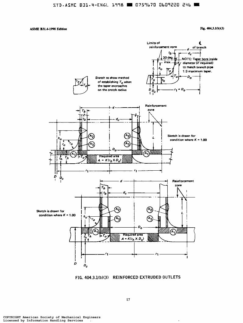
S T D - A S M E B I L a L i - E N G L 2978 0759b70 Ob0722U 2Lib m
ASME B31.4-1998 Edition Fig. 4043.1@)(3)
Limits of t reinforcement zone
diameter (if required) to match branch pipa 1:3 maximum taper.
Sketch to show method TO
of establishing To when the taper encroaches on the crotch radius
Reinforcement
Sketch is drawn for
Reinforcement
Sketch ir drawn for condition where K = 1 .O0
= 1.00
FIG. 404.3.1(b)(3) REINFORCED EXTRUDED OUTLETS
17
COPYRIGHT American Society of Mechanical EngineersLicensed by Information Handling ServicesCOPYRIGHT American Society of Mechanical EngineersLicensed by Information Handling Services
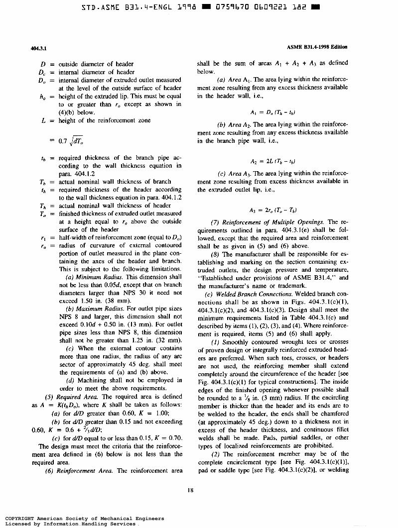
4043.1
D = outside diameter of header D, = internal diameter of header Do = internal diameter of extruded outlet measured
at the level of the outside surface of header ho = height of the extruded lip. This must be equal
to or greater than ro except as shown in (4)(b) below.
L = height of the reinforcement zone
= 0.7 ,/dTo
tb = required thickness of the branch pipe ac- cording to the wall thickness equation in para. 404.1.2
Tb = actual nominal wall thickness of branch th = required thickness of the header according
to the wall thickness equation in para. 404.1.2 Th = actual nominal wall thickness of header To = finished thickness of extruded outlet measured
at a height equal to ro above the outside surface of the header
ri = half-width of reinforcement zone (equal to Do) r, = radius of curvature of external contoured
portion of outlet measured in the plane con- taining the axes of the header and branch. This is subject to the following limitations.
(a) Minimum Radius. This dimension shall not be less than 0.05d, except that on branch diameters larger than NPS 30 it need not exceed 1.50 in. (38 mm).
(6) Maximum Radius. For outlet pipe sizes NPS 8 and larger, this dimension shall not exceed 0.1Od + 0.50 in. (13 mrn). For outlet pipe sizes less than NPS 8, this dimension shall not be greater than 1.25 in. (32 mm).
(c ) When the external contour contains more than one radius, the radius of any arc sector of approximately 45 deg. shall meet the requirements of (a) and (b) above.
(d) Machining shall not be employed in order to meet the above requirements.
(5) Required Area. The required area is defined as A = K(thDo), where K shall be taken as follows:
( a ) for d/D greater than 0.60, K = 1.00; (b) for d/D greater than 0.15 and not exceeding
(c ) for d D equal to or less than 0.15, K = 0.70. The design must meet the criteria that the reinforce-
ment area defined in (6) below is not less than the required area.
(6) Reinforcement Area. The reinforcement area
0.60, K = 0.6 + 2 / d D ;
ASME B31.4-1998 Edition
shall be the sum of areas A , + A2 + A3 as defined below.
(a) Area A,. The area lying within the reinforce- ment zone resulting from any excess thickness available in the header wall, i.e.,
A I = Do (Th - t h )
(6) Area AZ. The area lying within the reinforce- ment zone resulting from any excess thickness available in the branch pipe wall, ¡.e.,
A2 = 2L (Tb - tb)
(c) Area A3. The area lying within the reinforce- ment zone resulting from excess thickness available in the extruded outlet lip, i.e.,
A3 = 2r0 (To - Tb)
(7) Reinforcement of Multiple Openings. The re- quirements outlined in para. 404.3.1(e) shall be fol- lowed, except that the required area and reinforcement shall be as given in (5) and (6) above.
(8) The manufacturer shall be responsible for es- tablishing and marking on the section containing ex- truded outlets, the design pressure and temperature, “Established under provisions of ASME B31.4,” and the manufacturer’s name or trademark.
(c ) Welded Branch Connections. Welded branch con- nections shall be as shown i n Figs. 404.3.1(~)(1), 404.3.1(~)(2), and 404.3.1(~)(3). Design shall meet the minimum requirements listed in Table 404.3.1(c) and described by items (1), (2), (3), and (4). Where reinforce- ment is required, items ( 5 ) and (6) shall apply.
( I ) Smoothly contoured wrought tees or crosses of proven design or integrally reinforced extruded head- ers are preferred. When such tees, crosses, or headers are not used, the reinforcing member shall extend completely around the circumference of the header [see Fig. 404.3.1(c>(l) for typical constructions]. The inside edges of the finished opening whenever possible shall be rounded to a ‘/s in. (3 mm) radius. If the encircling member is thicker than the header and its ends are to be welded to the header, the ends shall be chamfered (at approximately 45 deg.) down to a thickness not in excess of the header thickness, and continuous fillet welds shall be made. Pads, partial saddles, or other types of localized reinforcements are prohibited.
(2) The reinforcement member may be of the complete encirclement type [see Fig. 404.3.1(c)( i)]. pad or saddle type [see Fig. 404.3.1(~)(2)], or welding
18
COPYRIGHT American Society of Mechanical EngineersLicensed by Information Handling ServicesCOPYRIGHT American Society of Mechanical EngineersLicensed by Information Handling Services

ASME B31.4-1998 Edition
GENERAL NOTE: Since fluid pressure is exerted on both sides of pipe metal under tee, the pipe metal does not provide reinforcement.
Tee Type
I I I ' I I
Saddle and Sleeve Type
GENERAL NOTE:
Fig. 404.3.1(~)(1)
I around circumference
GENERAL NOTE: Provide hole in reinforcement to reveal leakage in buried welds and to provide venting during welding and heat treatment [see para. 404.3.l(d)(B)]. Not required for tee type.
Sleeve Type
Saddle Type
If the encircling member for tee, sleeve, or saddle type is thicker than the header and its ends are to be welded to the header. the ends shall be chamfered (at approximately 45 deg.) down to a thickness not in excess of the header thickness.
FIG. 404.3.1(~)(1) WELDING DETAILS FOR OPENINGS WITH COMPLETE ENCIRCLEMENT TYPES OF REINFORCEMENT
19
COPYRIGHT American Society of Mechanical EngineersLicensed by Information Handling ServicesCOPYRIGHT American Society of Mechanical EngineersLicensed by Information Handling Services

STD=ASME B31-4-ENGL 2778 0757b70 Ob09223 T 5 5 M
Fig. WJ. l (cM2) ASME B31.4-199% Edition
404.3.1 (cl (3) or
Sddk
or
P d
404.3.1 (c l (3)
M = nominal wall thickness of pad reinforcement Th = nominal wall thickness of heeder Wl (min.) = the smaller of Tb , M , or 3/8 in. (10 mm)
Mb = nominal wall thickness of saddle at branch end W2 (max.) = approx. ï h Mh = nominal wall thickness of saddle at header end W2 (min.) = the ma i le r of 0.7 ï h , 0.7 M, or 1/2 in. (13 mm) N = 1/16 in. (1.5 mm) (min.), 118 in. (3 mm) (max.)(unless w3 (max.) = apclrox. ïh
W3 (min.) = the smaller of 0.7 Th, 0.7 Mh, or 112 in. (13 mm) bnck welded or backing strip is used) Tb = nominal wall thickness of branch W4 (min.) = the smaller o f Tb, M b or 3 /8 in. (10 mm)
member
GENERAL NOTES: (a) All welds are to have equal leg dimensions and a minimum throat equal to 0.707 x leg dimension. (b) If the reinforcing member is thicker at its edge than the header, the edge shall be chamfered [at
approximately 45 deg.) down to a thickness such that leg dimensions of the fillet weld shall be within the minimum and maximum dimensions specified above.
(c) A hole shall be provided in reinforcement to reveal leakage in buried welds and to provide venting during welding and heat treatment [see para. 404.3.1(d)(8)].
FIG. 404.3.1(~)(2) WELDING DETAILS FOR OPENINGS WITH LOCALIZED TYPE REINFORCEMENT
20
COPYRIGHT American Society of Mechanical EngineersLicensed by Information Handling ServicesCOPYRIGHT American Society of Mechanical EngineersLicensed by Information Handling Services

MME 831.44998 Edition
or
4043.1
GENERAL NOTE: When a welding saddle is used, it shatl be inserted over this type of connection. See Fig. 404.3.1 (cl (2).
Th = nominal wall thickness of header ïb = nominal wall thickness of branch
WI (min.) = the smaller of Th Tb or 3/8 in. (10 mml N = 1/16 in. (1.5 mm) (min.), 118 in. (3 mm) (max.)
unless back welded or backing strip is used
FIG. 404.3.1(~)(3) WELDING DETAILS FOR OPENINGS WITHOUT REINFORCEMENT OTHER THAN THAT IN HEADER AND BRANCH WALLS
TABLE 404.3.1k) DESIGN CRITERIA FOR WELDED BRANCH CONNECTIONS
Ratio of Diameter of Hole Cut for Branch Connection to Nominal Header Diameter Ratio of Design Hoop
Stress to Specfied Min. Yield Strength More than 25%
of the Header 25% or less Through 50% More Than 50%
20% or less (4) (4 ) (4)(5)
More than 20% through 50%
More than 50% (2)(3) (2) (1)
outlet fitting type. Where attached to the header by fillet welding, the edges of the reinforcement member shall be chamfered (at approximately 45 deg.) down to a thickness not in excess of the header thickness. The diameter of the hole cut in the header pipe for a branch connection shall not exceed the outside diameter of the branch connection by more than v4 in. (6 mm).
(3) Reinforcement for branch connections with hole cut NPS 2 or smaller is not required [see Fig. 404.3.1(~)(3) for typical details]; however, care shall
be taken to provide suitable protection against vibrations and other external forces to which these small branch connections are frequently subjected.
(4) Reinforcement of opening is not mandatory; however, reinforcement may be required for cases in- volving pressure over 100 psi (7 bar), thin wall pipe, or severe external loads.
(5) If a reinforcement member is required, and the branch diameter is such that a localized type of reinforcement member would extend around more than
21
COPYRIGHT American Society of Mechanical EngineersLicensed by Information Handling ServicesCOPYRIGHT American Society of Mechanical EngineersLicensed by Information Handling Services

STD-ASME B3L-4-ENGL 1778 0759b70 üb09225 828 =
4043.1
half the circumference of the header, then a complete encirclement type of reinforcement member shall be used, regardless of the design hoop stress, or a smoothly contoured wrought steel tee or cross of proven design or extruded header may be used.
(6) The reinforcement shall be designed in accord- ance with para. 404.3. I(d).
(d) Reinforcement of Single Openings (I) When welded branch connections are made to
pipe in the form of a single connection, or in a header or manifold as a series of connections, the design shall be adequate to control the stress levels in the pipe within safe limits. The construction shall take cognizance of the stresses in the remaining pipe wall due to the opening in the pipe or header, the shear stresses produced by the pressure acting on the area of the branch opening, and any external loading due to thermal movement, weight, vibration, etc., and shall meet the minimum requirements listed in Table 404.3.1(c). The following paragraphs provide design rules based on the stress intensification created by the existence of a hole in an otherwise symmetrical section. External loadings, such as those due to thermal expansion or unsupported weight of connecting pipe, have not been evaluated. These factors should be given attention in unusual designs or under conditions of cyclic loading.
When pipe which has been cold worked to meet the specified minimum yield strength is used as a header containing single or multiple welded branch connections, stresses shall be in accordance with para. 402.3.1(d).
(2) The reinforcement required in the crotch section of a welded branch connection shall be determined by the rule that the metal area available for reinforcement shall be equal to or greater than the required cross- sectional area as defined in (3) below and in Fig. 404.3.l(d)(2).
(3) The required cross-sectional area AR is defined as the product of d times th:
where d = length of the finished opening in the header
wall measured parallel to the axis of the header th = design header wall thickness required by para.
404.1.2. For welded pipe, when the branch does not intersect the longitudinal or spiral weld of the header, the allowable stress value for seamless pipe of comparable grade may be used in determining rh for the purpose of reinforcement calculations only. When the
M M E B31.4-1998 Edition
branch does intersect the longitudinal or spiral weld of the header, the allowable stress value S of the header shall be used in the calculation. The allowable stress value S of the branch shall be used in calculating tb.
(4) The area available for the reinforcement shall be the sum of:
(a) the cross-sectional area resulting from any excess thickness available in the header thickness (over the minimum required for the header as defined in para. 404.1.2) and which lies within the reinforcement area as defined in para. 404.3.1(d)(5) below;
(6) the cross-sectional area resulting from any excess thickness available in the branch wall thickness over the minimum thickness required for the branch and which lies within the reinforcement area as defined in para. 404.3.1(d)(5) below;
(c) the cross-sectional area of all added reinforc- ing metal, including weld metal, which is welded to the header wall and lies within the reinforcement area as defined in para. 404.3.1(d)(5) below.
(5) The reinforcement area is shown in Fig. 404.3.1(d)(2) and is defined as a rectangle whose length shall extend a distance d [see para. 404.3.1(d)(3)] on each side of the transverse centerline of the finished opening and whose width shall extend a distance of 2v2 times the header wall thickness from the outside surface of the header wall, except that in no case shall it extend more than 21/2 times the thickness of the branch wall from the outside surface of the header or of the reinforcement if any.
(6) The material of any added reinforcement shall have an allowable working stress at least equal to that of the header wall, except that material of lower allow- able stress may be used if the area is increased in direct ratio of the allowable stresses for header and reinforcement material respectively.
(7) The material used for ring or saddle reinforce- ment may be of specifications differing from those of the pipe, provided the cross-sectional area is made in correct proportions to the relative strength of the pipe and reinforcement materials at the operating tempera- tures, and provided it has welding qualities comparable to those of the pipe. No credit shall be taken for the additional strength of material having a higher strength than that of the part to be reinforced.
(8) When rings or saddles are used which cover the weld between branch and header, a vent hole shall be provided in the ring or saddle to reveal leakage in the weld between branch and header and to provide venting during welding and heat treating operations.
22
COPYRIGHT American Society of Mechanical EngineersLicensed by Information Handling ServicesCOPYRIGHT American Society of Mechanical EngineersLicensed by Information Handling Services

MME 831.41998 Edition
A .
L = smaller of 2-112 Th
"Area of reinforcement" enclosed by - - - - lines
A, = (T, - r,,) d 4 = 2 (r, - a L
Reinforcement area required A,, = ât, Area available as reinforcement = A, + 4 + 4
4 = summation of area of all added reinforcement, including
A, + 4 + 4 must be equal to or greater than A,, where
weld areas that lie within the "area of reinforcement"
T, = nominal wall thickness of header Tb = nominal wall thickness of branch tb = design branch wall thickness required by para. 404.1.2 th = design header wall thickness required by para. 404.1.2 d = length of the finished opening in the header wall
(measured parallel to the axis of the header) M = actual (by measurement) or nominal
thickness of added reinforcement
FIG. 404.3.1(d)(2) REINFORCEMENT OF BRANCH CONNECTIONS
Vent holes shall be plugged during service to prevent crevice corrosion between pipe and reinforcing member, but no plugging material shall be used that would be capable of sustaining pressure within the crevice.
(9) The use of ribs or gussets shall not be consid- ered as contributing to reinforcement to the branch connection. This does not prohibit the use of ribs or gussets for purposes other than reinforcement, such as stiffening.
(10) The branch shall be attached by a weld for the full thickness of the branch or header wall plus a fillet weld W1 as shown in Figs. 404.3.1(~)(2) and 404.3.1(~)(3). The use of concave fillet welds is to be preferred to minimize corner stress concentration. Ring or saddle reinforcement shall be attached as shown by
4043.1
Fig. 404.3.1(~)(2). If the reinforcing member is thicker at its edge than the header, the edge shall be chamfered (at approximately 45 deg.) down to a thickness so leg dimensions of the fillet weld shall be within the mini- mum and maximum dimensions specified in Fig. 404.3.1(~)(2).
(1 1 ) Reinforcement rings and saddles shall be accu- rately fitted to the parts to which they are attached. Figures 404.3.1(c)( 1) and 404.3.1(~)(2) illustrate some acceptable forms of reinforcement.
Branch connections attached at an angle less than 90 deg. to the header become progressively weaker as the angle becomes less. Any such design shall be given individual study, and sufficient reinforcement shall be provided to compensate for the inherent weakness of
23
COPYRIGHT American Society of Mechanical EngineersLicensed by Information Handling ServicesCOPYRIGHT American Society of Mechanical EngineersLicensed by Information Handling Services

STD*ASME B31.4-ENGL 1998 = 0759b7D Ob01227 bTO
4043.1404.7 M M E B31.4-199% Eùition
such construction. The use of encircling ribs to support 404.5 Pressure Design of Flanges the flat or reentering surfaces is permissible and may be included in the strength considerations. The designer is cautioned that stress concentrations near the ends of partial ribs, straps, or gussets may defeat their reinforc- ing value, and their use is not recommended.
(e ) Reinforcement of Multiple Openings (I) Two adjacent branches should preferably be
spaced at such a distance that their individual effective areas of reinforcement do not overlap. When two or more adjacent branches are spaced at less than two times their average diameter (so that their effective areas of reinforcement overlap), the group of openings shall be reinforced in accordance with para. 404.3.1(d). The reinforcing metal shall be added as a combined reinforcement, the strength of which shall equal the combined strengths of the reinforcements that would be required for the separate openings. In no case shall any portion of a cross section be considered to apply to more than one opening, or be evaluated more than once in a combined area.
(2) When more than two adjacent openings are to be provided with a combined reinforcement, the minimum distance between centers of any two of these openings shall preferably be at least 1’/2 times their average diameter, and the area of reinforcement between them shall be at least equal to 50% of the total required for these two openings on the cross section being considered.
(3) When two adjacent openings as considered under para. 404.3.l(e)(2) have the distance between centers less than 173 times their average diameter, no credit for reinforcement shall be given for any of the metal between these two openings.
(4) When pipe which has been cold worked to meet the specified minimum yield strength is used as a header containing single or multiple welded branch connections, stresses shall be in accordance with para. 402.3.1(d).
(5) Any number of closely spaced adjacent open- ings, in any arrangement, may be reinforced as if the group were treated as one assumed opening of a diameter enclosing all such openings.
404.3.4 Attachments. External and internal attach- ments to piping shall be designed so they will not cause flattening of the pipe, excessive localized bending stresses, or harmful thermal gradients in the pipe wall. See para. 421.1 for design of pipe supporting elements.
404.5.1 General (a) The design of flanges manufactured in accordance
with para. 408.1 and the standards listed in Table 426.1 shall be considered suitable for use at the pressure- temperature ratings as set forth in para. 402.2.1.
(b) It is permissible to inside taper bore the hubs on welding neck flanges having dimensions complying with ASME B16.5 when they are to be attached to thin wall pipe. It is recommended that the taper shall not be more abrupt than a ratio of 1:3. MSS SP-44, NPS 26, and larger “pipeline” flanges are designed for attachment to thin wall pipe and are preferred for this service.
(c) Where conditions require the use of flanges other than those covered in para. 408.1, the flanges shall be designed in accordance with Appendix II of Section VIII, Division 1, of the ASME Boiler and Pressure Vessel Code.
(d) Slip-on flanges of rectangular cross section shall be designed so that flange thickness is increased to provide strength equal to that of the corresponding hubbed slip-on flange covered by ASME B16.5, as determined by calculations made in accordance with the ASME Boiler and Pressure Vessel Code, Section VIII. Division 1.
(981
404.6 Reducers (98)
(a) Reducer fittings manufactured in accordance with ASME B 16.5, ASME B 16.9, or MSS SP-75 shall have pressure-temperature ratings based on the same stress values as were used in establishing the pressure-tempera- ture limitations for pipe of the same or equivalent material.
(b) Smoothly contoured reducers fabricated to the same nominal wall thickness and of the same type of steel as the adjoining pipe shall be considered suitable for use at the pressure-temperature ratings of the adjoin- ing pipe. Seam welds of fabricated reducers shall be inspected by radiography or other accepted nondestruc- tive methods (visual inspection excepted).
(c) Where appropriate, changes in diameter may be accomplished by elbows, reducing outlet tees, or valves.
404.7 Pressure Design of Other Pressure Containing
Pressure containing components which are not cov- ered by the standards listed in Tables 423.1 or 426.1 and for which design equations or procedures are not given herein may be used where the design of similarly
Components
24
COPYRIGHT American Society of Mechanical EngineersLicensed by Information Handling ServicesCOPYRIGHT American Society of Mechanical EngineersLicensed by Information Handling Services

ASME B31.4-1998 Edition 404.7406.2.1
shaped, proportioned, and sized components has been proven satisfactory by successful performance under comparable service conditions. (Interpolation may be made between similarly shaped proved components with small differences in size or proportion.) In the absence of such service experience, the pressure design shall be based on an analysis consistent with the general design philosophy embodied in this Code, and substanti- ated by at least one of the following:
(u) proof tests (as are described in UG-101 of Section VIII, Division 1, of the ASME Boiler and Pressure Vessel Code);
(b) experimental stress analysis (such as described in Appendix 6 of Section VIII, Division 2, of the ASME Boiler and Pressure Vessel Code);
(c) engineering calculations.
( e ) Coated or Lined Pipe. External or internal coat- ings or linings of cement, plastics, or other materials may be used on steel pipe conforming to the requirements of this Code. These coatings or linings shall not be consid- ered to add strength.
406 FITTINGS, ELBOWS, BENDS, AND INTERSECTIONS
406.1 Fittings
406.1.1 General (98) (u) Steel Butt Welding Fittings. When steel butt
welding fittings [see paras. 404.2.2(b), 404.3.1(a)(2), and 404.3.1(a)(3)] are used, they shall comply with ASME B16.9, ASME B16.28, or MSS SP-75.
(b) Steel Flanged Fittings. When steel flanged fittings [see paras. 404.3.1(a)(l) and 404.5.11 are used, they shall comply with ASME B16.5.
(c) Fittings Exceeding Scope of Standard Sizes. Fit- tings exceeding scope of standard sizes or otherwise departing from dimensions listed in the standards re-
PART 3 DESIGN APPLICATIONS OF PIPING
COMPONENTS SELECTION AND LIMITATIONS
405 PIPE fe&d to in para. 406.1.l(a) or 406.1.l(b) may be used, provided the designs meet the requirements of paras. 403 and 404.
405.2 Metallic Pipe 406.2 Bends, Miters, and Elbows
405.2.1 Ferrous Pipe (a) New pipe of the specifications listed in Table
423.1 may be used in accordance with the design equation of para. 404.1.2 subject to the testing require- ments of paras. 437.1.4, 437.4.1, and 437.4.3.
(b) Used pipe of known specification listed in Table 423.1 may be used in accordance with the design
406.2.1 Bends Made From Pipe (u) Bends may be made by bending the pipe when
they are designed in accordance With Para. 404.2.1 and made in accordance with para. 434.7.1.
(6) Except as permitted under para. 406.2.1(c), the minimum radius of field cold bends shall be as follows:
equation of para. 404.1.2 subject to the testing require- ments of paras. 437.4.1, 437.6.1, 431.6.3, and 437.6.4.
( c ) New or used pipe of unknown or ASTM A 120 specification may be used in accordance with the design equation in para. 404.1.2 with an allowable stress value as specified in para. 402.3.1(c) and subject to the testing requirements of paras. 437.4.1,437.4.3,437.6.1,437.6.3, 437.6.4, and 437.6.5, if 24,000 psi (165 MPa) yield strength is used to establish an allowable stress value; or para. 437.4.1, and paras. 437.6.1 through 437.6.7 inclusive, if a yield strength above 24,000 psi (165 MPa) is used to establish an allowable stress value.
(d) Pipe which has been cold worked in order to meet the specified minimum yield strength and is subsequently heated to 600°F (300°C) or higher (weld- ing excepted) shall be limited to a stress value as noted in para. 402.3.1(d).
Minimum Radius of Bend in Pipe Diameters Nominal Pipe Size
NPS 12 and smaller 18D 14 21 16 24 18 27
NPS 20 and larger 30
In some cases, thin wall pipe will require the use of an internal mandrel when being bent to the minimum radii tabulated above.
(c) Bends may be made by bending the pipe in sizes N P S 14 and larger to a minimum radius of 18D; however, bending pipe to radii approaching 18D that will meet requirements in para. 434.7.1(b) will be dependent upon wall thickness, ductility, ratio of pipe diameter to wall thickness, use of bending mandrel,
25
COPYRIGHT American Society of Mechanical EngineersLicensed by Information Handling ServicesCOPYRIGHT American Society of Mechanical EngineersLicensed by Information Handling Services

STD-ASME B31-4-ENGL 1778 0757b70 Ob07227 473
406.2.14ûó.6.4 ASME B31.4-1998 Edition
and skill of bending crew. Test bends shall be made to determine that the field bending procedure used produces bends meeting the requirements of para. 434.7.1(b) and that the wall thickness after bending is not less than the minimum permitted by the pipe specification.
406.2.2 Mitered Bends. In systems intended to oper- ate at a hoop stress of more than 20% of the specified minimum yield strength of the pipe, miter bends are prohibited. Miter bends not exceeding 12v2 deg. may be used in systems operated at a hoop stress of 20% or less of the specified minimum yield strength of the pipe, and the minimum distance between miters mea- sured at the crotch shall not be less than one pipe diameter. When the system is to be operated at a hoop stress of less than 10% of the specified minimum yield strength of the pipe, the restriction to 1 2 v ~ deg. maximum miter and distance between miters will not apply. Deflections caused by misalignment up to 3 deg. are not considered miter bends.
406.2.3 Factory Made Bends and Elbows (a) Factory made bends and factory made wrought
steel elbows may be used provided they meet the design requirements of paras. 404.2.1 and 404.2.2 and the construction requirements of para. 434.7.3. Such fittings shall have approximately the same mechanical properties and chemical composition as the pipe to which they are welded.
(b) If factory made elbows are used in cross-country lines, care should be taken to allow for passage of pipe-line scrapers.
406.2.4 Wrinkle Bends. Wrinkle bends shall not be used.
406.3 Couplings
Cast, malleable, or wrought iron threaded couplings are prohibited.
406.4 Reductions
(98) 406.4.1 Reducers. Reductions in line size may be made by the use of smoothly contoured reducers selected in accordance with ASME B16.5, ASME B16.9, or MSS SP-75, or designed as provided in para. 404.6.
406.5 Intersections
Intersection fittings and welded branch connections are permitted within the limitations listed in para. 406.1 (see para. 404.3 for design).
406.6 Closures
406.6.1 Quick Opening Closures. A quick opening closure is a pressure containing component (see para. 404.7) used for repeated access to the interior of a piping system. It is not the intent of this Code to impose the requirements of a specific design method on the designer or manufacturer of a quick opening closure.
Quick opening closures used for pressure containment under this Code shall have pressure and temperature ratings equal to or in excess of the design requirements of the piping system to which they are attached. See paras. 401.2.2 and 402.2.
Quick opening closures shall be equipped with safety locking devices in compliance with Section VIII, Divi- sion 1, UG-35(b) of the ASME Boiler and Pressure Vessel Code.
Weld end preparation shall be in accordance with para. 434.8.6.
406.6.2 Closure Fittings. Closure fittings commonly (98) referred to as “weld caps” shall be designed and manufactured in accordance with ASME B 16.9 or MSS SP-75.
406.6.3 Closure Heads. Closure heads such as flat, ellipsoidal (other than in para. 406.6.2 above), spherical, or conical heads are allowed for use under this Code. Such items shall be designed i: accordance with Section VIII, Division 1, of the ASME Boiler and Pressure Vessel Code. The maximum allowable stresses for materials used in these closure heads shall be established under the provisions of para. 402.3.
If welds are used in the construction of these heads, they shall be 100% radiographically inspected in accord- ance with the provisions of Section VIII, Division 1.
Closure heads shall have pressure and temperature ratings equal to or in excess of the requirement of para. 401.2.2. It is not the intent of this Code to necessarily extend the design requirements of Section VIII, Division 1, to other components in which closure heads are part of a complete assembly.
406.4.2 Orange Peel Swages. Orange peel swages are prohibited in systems operating at hoop stresses of more than 20% of the specified minimum yield strength of the pipe.
406.6.4 Fabricated Closures. Orange peel bull plugs are prohibited on systems operating at a hoop stress more than 20% of the specified minimum yield strength of the pipe. Fishtails and flat closures are permitted
26
COPYRIGHT American Society of Mechanical EngineersLicensed by Information Handling ServicesCOPYRIGHT American Society of Mechanical EngineersLicensed by Information Handling Services

STD-ASME 831-9-ENGL 1998 D 0759b70 Ob09230 195
ASME B31.4-1998 Edition
for NPS 3 pipe and smaller, operating at less than 100 psi (7 bar). Fishtails on pipe larger than NPS 3 are prohibited.
406.6.5 Bolted Blind Flange Closures. Bolted blind flange closures shall conform to para. 408.
407 VALVES
407.1 General
(a) Steel valves conforming to standards and specifi- cations listed in Tables 423.1 and 426.1 may be used. These valves may contain certain cast, malleable, or wrought iron parts as provided for in API 6D.
(b) Cast iron valves conforming to standards and specifications listed in Tables 423.1 and 426.1 may be used for pressures not to exceed 250 psi (17 bar). Care shall be exercised to prevent excessive mechanical loadings (see para. 408.5.4).
(c ) Working pressure ratings of the steel parts of steel valves are applicable within the temperature limita- tions of -20°F (-30°C) to 250°F (120°C) (see para. 401.3.1). Where resilient, rubberlike, or plastic materials are used for sealing, they shall be capable of withstand- ing the fluid, pressures, and temperatures specified for the piping system.
407.8 Special Valves
Special valves not listed in Tables 423.1 and 426.1 shall be permitted, provided that their design is of at least equal strength and tightness and they are capable of withstanding the same test requirements as covered in these standards, and structural features satisfy the material specification and test procedures of valves in similar service set forth in the listed standards.
408 FLANGES, FACINGS, GASKETS, AND BOLTING
408.1 Flanges
(981 408.1.1 General (a) Flanged connections shall conform to the require-
ments of paras. 408.1, 408.3, 408.4, and 408.5. (b) Steel Flanges Within Scope of Standard Sizes.
Welding neck, slip-on, threaded, and lapped companion flanges, reducing flanges, blind flanges, and flanges cast or forged integral with pipe, fittings, or valves, conforming to ASME B 16.5 or MSS SP-44, are permit- ted in the sizes listed in these standards and for the
406.6.4.408.4.2
pressure-temperature ratings shown in para. 402.2.1. The bore of welding neck flanges should correspond to the inside diameter of the pipe with which they are to be used. See para. 404.5.1 for design.
(c ) Cast Iron Flanges Within Scope of Standard Sizes. Cast iron flanges are prohibited, except those which are an integral part of cast iron valves, pressure vessels, and other equipment and proprietary items [see para. 407.l(b) and 423.2.4(b)].
(d) Flanges Exceeding Scope of Standard Sizes. Flanges exceeding scope of standard sizes or otherwise departing from dimensions listed in ASME B16.5 or MSS SP-44 may be used provided they are designed in accordance with para. 404.5.1.
(e ) Flanges of Rectangular Cross Section. Slip-on flanges of rectangular cross section may be used pro- vided they are designed in accordance with para. 404.5.1 (d).
408.3 Flange Facings
408.3.1 General (981
(a) Standard Facings. Steel or cast iron flanges shall have contact faces in accordance with ASME B16.5 or MSS SP-6.
(b) Special Facings. Special facings are permissible provided they are capable of withstanding the same tests as those in ASME B16.5. See para. 408.5.4 for bolting steel to cast iron flanges.
408.4 Gaskets
408.4.1 General. Gaskets shall be made of materials which are not injuriously affected by the fluid in the piping system, and shall be capable of withstanding the pressures and temperatures to which they will be subjected in service.
408.4.2 Standard Gaskets (981
(a) Gaskets conforming to ASME B16.20 or to ASME B16.21 may be used.
(b) Metallic gaskets other than ring type or spirally wound metal asbestos shall not be used with ANSI Class 150 or lighter flanges.
(c ) The use of metal or metal jacketed asbestos (either plain or corrugated) is not limited [except as provided in para. 408.4.2(b)] as to pressure, provided that the gasket material is suitable for the service temperature. These types of gaskets are recommended for use with the small male and female or the small
27
COPYRIGHT American Society of Mechanical EngineersLicensed by Information Handling ServicesCOPYRIGHT American Society of Mechanical EngineersLicensed by Information Handling Services

4ûû.4.2-414.1 ASME B31.4-1998 E d i t h
tongue and groove facings. They may also be used with steel flanges with any of the following facings: lapped, large male and female, large tongue and groove, or raised face.
(d) Asbestos composition gaskets may be used as permitted in ASME B16.5. This type of gasket may be used with any of the various flange facings except small male and female, or small tongue and groove.
(e) Rings for ring joints shall be of dimensions established in ASME B16.20. The materials for these rings shall be suitable for the service conditions encoun- tered and shall be softer than the flanges.
408.4.3 Special Gaskets. Special gaskets, including insulating gaskets, may be used provided they are suitable for the temperatures, pressures, fluids, and other conditions to which they may be subjected.
408.5 Bolting
198) 408.5.1 General (a) Bolts or stud bolts shall extend completely
through the nuts. (6) Nuts shall conform with ASTM A 194 or A 325,
except that A 307 Grade B nuts may be used on ASME Class 150 and ASME Class 300 flanges.
(98) 408.5.2 Bolting for Steel Flanges. Bolting shall conform to ASME B16.5.
408.5.3 Bolting for Insulating Flanges. For insulat- ing flanges, v8 in. (3 mm) undersize bolting may be used provided that alloy steel bolting material in accordance with ASTM A 193 or A 354 is used.
408.5.4 Bolting Steel to Cast Iron Flanges. When bolting Class 150 steel flanges to Class 125 cast iron flanges, heat treated carbon steel or alloy steel bolting (ASTM A 193) may be used only when both flanges are flat face and the gasket is full face; otherwise, the bolting shall have a maximum tensile strength no greater than the maximum tensile strength of ASTM A 307 Grade B. When bolting Class 300 steel flanges to Class 250 cast iron flanges, the bolting shall have a maximum tensile strength no greater than the maximum tensile strength of ASTM A 307 Grade B. Good practice indicates that the flange should be flat faced.
408.5.5 Bolting for Special Flanges. For flanges designed in accordance with para. 404.5.1 [see paras. 408.1.l(d) and 408.1.l(e)], bolting shall conform to the applicable section of Section VIII, Division 1, of the ASME Boiler and Pressure Vessel Code.
409 USED PIPING COMPONENTS AND EQUIPMENT
Used piping components, such as fittings, elbows, bends, intersections, couplings, reducers, closures, flanges, valves, and equipment, may be reused. [Reuse of pipe is covered by para. 405.2.l(b).] However, such components and equipment shall be cleaned and examined; reconditioned, if necessary, to insure that they meet all requirements for the intended service; and sound and free of defects.
In addition, reuse shall be contingent on identification of the specification under which the item was originally produced. Where the specification cannot be identified, use shall be restricted to a maximum allowable operating pressure based on a yield strength of 24,000 psi (165 MPa) or less.
PART 4 SELECTION AND LIMITATION OF
PIPING JOINTS
411 WELDED JOINTS
411.2 Butt Welds
Butt welded joints shall be in accordance with Chap- ter V.
412 FLANGED JOINTS
412.1 General
Flanged joints shall meet the requirements of para. 408.
414 THREADED JOINTS
414.1 General (98)
All external pipe threads on piping components shall be taper pipe threads. They shall be line pipe threads in accordance with API 5B, or NPT threads in accord- ance with ASME B1.20.1. All internal pipe threads on piping components shall be taper pipe threads, except for sizes N P S 2 and smaller with design gage pressures not exceeding 150 psi (10 bar), in which case straight threads may be used.
Least nominal wall thickness for threaded pipe shall be standard wall (see ASME B36.10M).
28
COPYRIGHT American Society of Mechanical EngineersLicensed by Information Handling ServicesCOPYRIGHT American Society of Mechanical EngineersLicensed by Information Handling Services

MME B31.4-1998 Edition
418 SLEEVE, COUPLED, AND OTHER PATENTED JOINTS
418.1 General
418-419.6.4
(d ) Expansion of aboveground lines may be pre- vented by anchoring them so that longitudinal expansion, or contraction, due to thermal and pressure changes is absorbed by direct axial compression or tension of the pipe in the same way as for buried piping. In addition, however, bem bending stresses shall be included and
due to longitudinal compressive forces shall
Steel connectors and Swivels complying with API
be
(u) a prototype joint has been subject to proof tests
6D may be Sleeve* and Other patented the possible elastic instability of the pipe, and its joints, except as limited in Para- 423.2-4(b)9 used provided: be considered.
to determine the safety of the joints under simulated service conditions. When vibration, fatigue, cyclic con- ditions, low temperature, thermal expansion, or other severe conditions are anticipated, the applicable condi- tions shall be incorporated in the tests.
(b) adequate provision is made to prevent separation of the joint and to prevent longitudinal or lateral movement beyond the limits provided for in the joining member.
PART 5 EXPANSION. FLEXIBILITY.
419.5 Flexibility
419.5.1 Means of Providing Flexibility. If expan- sion is not absorbed by direct axial compression of the pipe, flexibility shall be provided by the use of bends, loops, or offsets; or provision shall be made to absorb thermal strains by expansion joints or couplings of the slip joint, ball joint, or bellows type. If expansion joints are used, anchors or ties of sufficient strength and rigidity shall be installed to provide for end forces due to fluid pressure and other causes.
419.6 Properties
STRUCTURAL' ATTACHMENTS, SUPPORTS, AND RESTRAINTS
419.6.1 Coefficient of Thermal Expansion. The lin- ear coefficient of thermal expansion for carbon and low alloy high tensile steel may be taken as 6.5 x 10" in./in./"F for temperatures up to 250°F (11.7 x 10" mm/mm/"c for temperatures up to 120"~). 419 EXPANSION AND FLEXIBILITY
419.1 General
(a) This Code is applicable to both aboveground and buried piping and covers all classes of materials permitted by this Code. Formal calculations shall be required where reasonable doubt exists as to the ade- quate flexibility of the piping.
(b) Piping shall be designed to have sufficient flexi- bility to prevent expansion or contraction from causing excessive stresses in the piping material, excessive bending moments at joints, or excessive forces or moments at points of connection to equipment or at anchorage or guide points. Allowable forces and mo- ments on equipment may be less than for the connected piping.
(c) Expansion calculations are necessary for buried lines if significant temperature changes are expected, such as when the line is to carry a heated oil. Thermal expansion of buried lines may cause movement at points where the line terminates, changes in direction, or changes in size. Unless such movements are restrained by suitable anchors, the necessary flexibility shall be provided.
419.6.2 Moduli of Elasticity. Flexibility calculations shall be based on the modulus of elasticity at ambient temperature.
419.6.3 Poisson's Ratio. Poisson's ratio shall be taken as 0.3 for steel.
419.6.4 Stress Values (a) General. There are fundamental differences in
loading conditions for the buried, or similarly restrained, portions of the piping and the aboveground portions not subject to substantial axial restraint. Therefore, different limits on allowable longitudinal expansion stresses are necessary. (6) Restrained Lines. The net longitudinal compres-
sive stress due to the combined effects of temperature rise and fluid pressure shall be computed from the equation:
where SL = longitudinal compressive stress, psi (MPa) s h = hoop stress due to fluid pressure, psi (MPa)
29
COPYRIGHT American Society of Mechanical EngineersLicensed by Information Handling ServicesCOPYRIGHT American Society of Mechanical EngineersLicensed by Information Handling Services
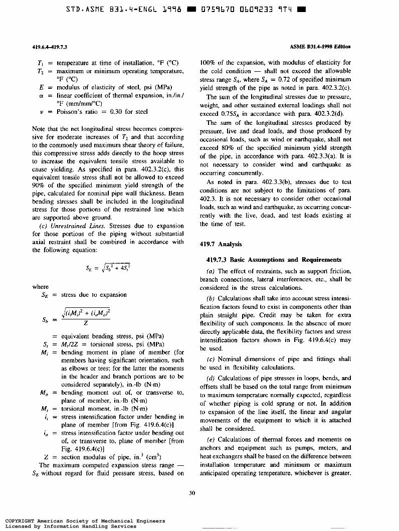
S T D - A S M E B31.4-ENGL 1778 0757b70 Ob07233 7 T 4 D
419.6.4-419.73
T, = temperature at time of installation, O F (OC) T2 = maximum or minimum operating temperature,
E = modulus of elasticity of steel, psi (MPa) o! = linear coefficient of thermal expansion, inJin./
v = Poisson's ratio = 0.30 for steel
OF ( O C )
OF (mm/mm/"C)
Note that the net longitudinal stress becomes compres- sive for moderate increases of T2 and that according to the commonly used maximum shear theory of failure, this compressive stress adds directly to the hoop stress to increase the equivalent tensile stress available to cause yielding. As specified in para. 402.3.2(c), this equivalent tensile stress shall not be allowed to exceed 90% of the specified minimum yield strength of the pipe, calculated for nominal pipe wall thickness. Beam bending stresses shall be included in the longitudinal stress for those portions of the restrained line which are supported above ground.
(c) Unrestrained Lines. Stresses due to expansion for those portions of the piping without substantial axial restraint shall be combined in accordance with the following equation:
stress due to expansion
Z
equivalent bending stress, psi (MPa) M,/2Z = torsional stress, psi (MPa) bending moment in plane of member (for members having significant orientation, such as elbows or tees; for the latter the moments in the header and branch portions are to be considered separately), in.-lb (N.m) bending moment out of, or transverse to, plane of member, in.-lb (N.m) torsional moment, in.-lb (N.m) stress intensification factor under bending in plane of member [from Fig. 419.6.4(c)] stress intensification factor under bending out of, or transverse to, plane of member [from Fig. 419.6.4(c)] section modulus of pipe, in.3 (cm3)
The maximum computed expansion stress range - SE without regard for fluid pressure stress, based on
ASME B31.4-1998 Edition
100% of the expansion, with modulus of elasticity for the cold condition - shall not exceed the allowable stress range SA, where S A = 0.72 of specified minimum yield strength of the pipe as noted in para. 402.3.2(c).
The sum of the longitudinal stresses due to pressure, weight, and other sustained external loadings shall not exceed 0.75SA in accordance with para. 402.3.2(d).
The sum of the longitudinal stresses produced by pressure, live and dead loads, and those produced by occasional loads, such as wind or earthquake, shall not exceed 80% of the specified minimum yield strength of the pipe, in accordance with para. 402.3.3(a). It is not necessary to consider wind and earthquake as occurring concurrently.
As noted in para. 402.3.3(b), stresses due to test conditions are not subject to the limitations of para. 402.3. It is not necessary to consider other occasional loads, such as wind and earthquake, as occurring concur- rently with the live, dead, and test loads existing at the time of test.
419.7 Analysis
419.7.3 Basic Assumptions and Requirements
(a) The effect of restraints, such as support friction, branch connections, lateral interferences, etc., shall be considered in the stress calculations.
(b) Calculations shall take into account stress intensi- fication factors found to exist in components other than plain straight pipe. Credit may be taken for extra flexibility of such components. In the absence of more directly applicable data, the flexibility factors and stress intensification factors shown in Fig. 419.6.4(c) may be used.
(c) Nominal dimensions of pipe and fittings shall be used in flexibility calculations.
(ú) Calculations of pipe stresses in loops, bends, and offsets shall be based on the total range from minimum to maximum temperature normally expected, regardless of whether piping is cold sprung or not. In addition to expansion of the line itself, the linear and angular movements of the equipment to which it is attached shall be considered.
(e ) Calculations of thermal forces and moments on anchors and equipment such as pumps, meters, and heat exchangers shall be based on the difference between installation temperature and minimum or maximum anticipated operating temperature, whichever is greater.
30
COPYRIGHT American Society of Mechanical EngineersLicensed by Information Handling ServicesCOPYRIGHT American Society of Mechanical EngineersLicensed by Information Handling Services

ASME B31.4-1998 Edition Fig. 419.6.q~)
Stress Intensification Factor
Flexibility Flexibility Description Factor k ii (1) i, (2) Characteristic h Sketch
t R - 0.75 - 0.9 - 1.65 - Welding elbow,” 41 ’3 6i ’ or pipe bend h hz3 hzB ?
Closely spaced miter bend,’, 4, ’, ’ 5 < r(1 + t a n e)
1.52 - h5/6
0.9
h” -
0.9
miter bend,’, 4, ’, * h” ha3 5 2 r(1 + t a n e)
- 1.52 - Widely spaced - - r ( i +cot e)
0.75 1 +co t e t 2 r
- hZf3
0.9 t 0.75i0 + 0.25 - 4.4 - h2/3 1
Welding tee” per ASME 816.9
~~ ~~~ ~~~~~~~ ~
0.9
Saddle
0.75i0+ 0.25 - ( t + li2 fi* t” r
h2/3 1 Reinforced tee’, 4*
with pad or saddle
U nrei nforced fabricated tee’,
0.9 1 0.754, + 0.25 -
hu3
t r -
FIG. 419.6.4(c) FLEXIBILITY FACTOR k AND STRESS INTENSIFICATION FACTOR i
31
COPYRIGHT American Society of Mechanical EngineersLicensed by Information Handling ServicesCOPYRIGHT American Society of Mechanical EngineersLicensed by Information Handling Services
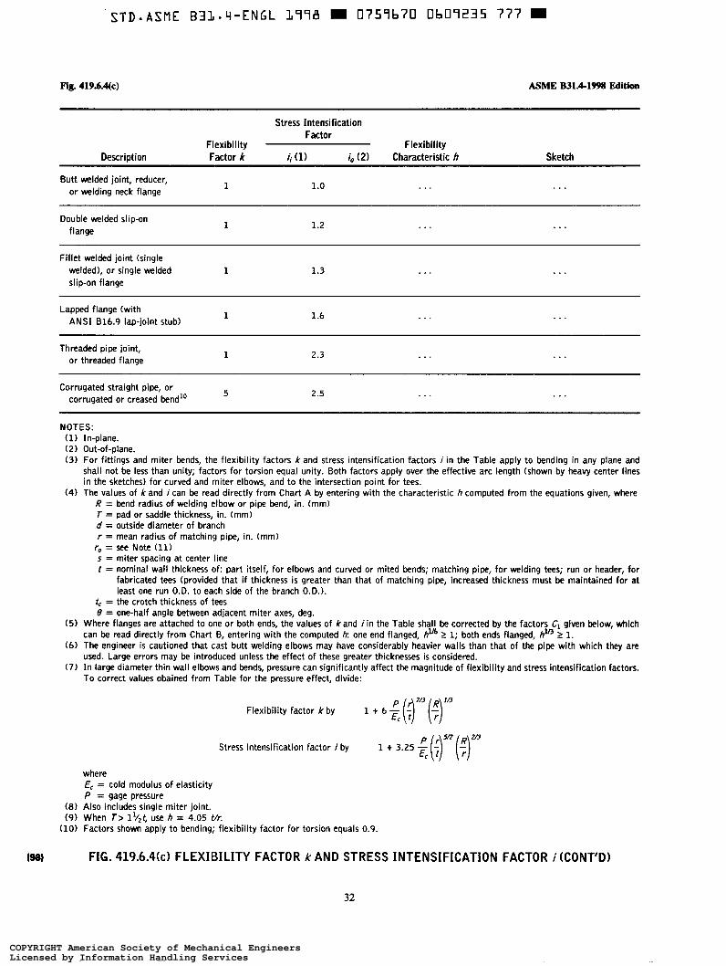
STD-ASME B31.4-ENGL 1778 m 0759b70 Ob07235 777 =
Fig. 419.ó.q~) ASME B31.4-1!298 Edition
Stress Intensification Factor
Flexibility Flexibility Description Factor k ii (1) i,, (2) Characteristic h Sketch
~~~~~ ~~
1 Butt welded joint, reducer,
or welding neck flange . . . ...
1 Double welded slip-on
flange 1.2 . . . . . .
Fillet welded joint (single welded), or single welded 1 slip-on flange
1.3 . . . . . .
1 Lapped flange (with
ANSI 816.9 lap-joint stub) 1.6 . . . . . .
1 2.3 . . . . . . Threaded pipe joint, or threaded flange
5 2.5 . . . . . . Corrugated straight pipe, or corrugated or creased bend'"
NOTES: (1) In-plane. (2) Out-of-plane. (3) For fittings and miter bends, the flexibility factors k and stress intensification factors i in the Table apply to bending in any plane and
shall not be less than unity; factors for torsion equal unity. Both factors apply over the effective arc length (shown by heavy center lines in the sketches) for curved and miter elbows, and to the intersection point for tees.
(4) The values of & and i can be read directly from Chart A by entering with the characteristic h computed from the equations given, where R = bend radius of welding elbow or pipe bend, in. (mm) T = pad or saddle thickness, in. (mm) d = outside diameter of branch r = mean radius of matching pipe, in. (mm)
r, = see Note (11) s = miter spacing at center line t = nominal wall thickness of: part itself, for elbows and curved or mited bends; matching pipe, for welding tees; run or header, for
fabricated tees (provided that if thickness is greater than that of matching pipe, increased thickness must be maintained for at least one run O.D. to each side of the branch O.D.).
tc = the crotch thickness of tees B = one-half angle between adjacent miter axes, deg.
( 5 ) Where flanges are attached to one or both ends, the values of &and i i n the Table shall be corrected by the factors Cl given below, which
(6) The engineer is cautioned that cast butt welding elbows may have considerably heavier walls than that of the pipe with which they are
(7) I n large diameter thin wall elbows and bends, pressure can significantly affect the magnitude of flexibility and stress intensification factors.
can be read directly from Chart 6, entering with the computed ir one end flanged, hu6 1 1; both ends flanged,
used. Large errors may be introduced unless the effect of these greater thicknesses is considered.
To correct values obained from Table for the pressure effect, divide:
2 1.
7/3 IB Flexibility factor k by
1 + 6 (7) (+) P r* m
Stress intensification factor i by 1 + 3.25 -g (;) (+) where EC = cold modulus of elasticity P = gage pressure
( 8 ) Also includes single miter joint. (9) When i> lv2t, use h = 4.05 Vr.
(10) Factors shown apply to bending; flexibility factor for torsion equals 0.9.
FIG. 419.6.4k) FLEXIBILITY FACTOR k AND STRESS INTENSIFICATION FACTOR i (CONT'D)
32
COPYRIGHT American Society of Mechanical EngineersLicensed by Information Handling ServicesCOPYRIGHT American Society of Mechanical EngineersLicensed by Information Handling Services

ASME B31.4a-2001 420-422.6.2
(11) Radius o f curvature of external contoured portion of outlet measured in the plane containing the axes of the run and branch. This i s subject to the following limitations: (a) minimum radius r,: the lesser of 0.05d or 38 mm (1.5 in.); (b) maximum radius r, shall not exceed:
(1) for branches DN200 (NPS 8 ) and larger, 0.10d+ 13 mm (0.50 in); ( 2 ) for branches less than DN200 (NPS 8), 32 mm (1.25 in.);
requirements of (a) and (b) above; (c) when the external contour contains more than one radius, the radius on any arc sector of approximately 45 deg. shall meet the
(d) machining shall not be employed in order to meet the above requirements.
FIG. 419.6.4k) FLEXIBILITY FACTOR k AND STRESS INTENSIFICATION FACTOR i (CONT’D)
420 LOADS ON PIPE SUPPORTING ELEMENTS
420.1 General
The forces and moments transmitted to connected equipment, such as valves, strainers, tanks, pressure vessels, and pumping machinery, shall be kept within safe limits.
421 DESIGN OF PIPE SUPPORTING EL EM EN T S
421.1 Supports, Braces, and Anchors
(a) Supports shall be designed to support the pipe without causing excessive local stresses in the pipe and without imposing excessive axial or lateral friction forces that might prevent the desired freedom of movement.
(b) Braces and damping devices may occasionally be required to prevent vibration of piping.
(c) All attachments to the pipe shall be designed to minimize the added stresses in the pipe wall because of the attachment. Nonintegral attachments, such as pipe clamps and ring girders, are preferred where they will fulfill the supporting or anchoring functions.
(d) If pipe is designed to operate above 20% SMYS, all attachments welded to the pipe shall be made to a separate cylindrical member that completely encircles the pipe, and this encircling member shall be welded to the pipe by continuous circumferential welds.
( e ) The applicable sections of MSS SP-58 for materi- als and design of pipe hangers and supports and of
MSS SP-69 for their selection and be used.
PART 6
PIPING AUXILIARY AND OTHER
application may
SPECIFIC
422 DESIGN REQUIREMENTS
422.3 Instrument and Other Auxiliary Liquid Petroleum or Liquid Anhydrous Ammonia Piping
All instrument and other auxiliary piping connected to primary piping and which operates at a gage pressure exceeding 15 psi (1 bar) shall be constructed in accord- ance with the provisions of this Code.
422.6 Pressure Disposal Piping
Pressure disposal or relief piping between pressure origin point and relief device shall be in accordance with this Code.
422.6.1 A full area stop valve may be installed between origin point and relief device providing such valve can be locked or sealed in the open position.
422.6.2 Disposal piping from relief device shall be connected to a proper disposal facility, which may be a flare stack, suitable pit, sump, or tank. This disposal piping shall have no valve between relief device and disposal facility unless such value can be locked or sealed in the open position.
33
COPYRIGHT American Society of Mechanical EngineersLicensed by Information Handling ServicesCOPYRIGHT American Society of Mechanical EngineersLicensed by Information Handling Services
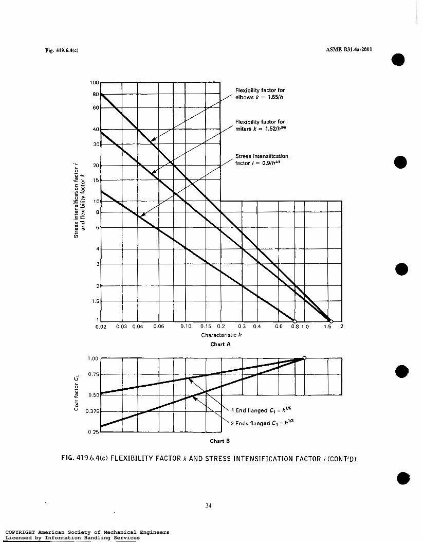
Fig. 419.6.4(c) ASME B31.4a-2001
Chart A
1 .o0
0.75 G L
c O
0.50 L L
O
u 0.375 ‘ 1 End flanged C, = h”6
2 Ends flanged Cl = h’’ 0.25
Chart B
FIG. 419.6.4(c) FLEXIBILITY FACTOR k AND STRESS INTENSIFICATION FACTOR i (CONT’D)
34
COPYRIGHT American Society of Mechanical EngineersLicensed by Information Handling ServicesCOPYRIGHT American Society of Mechanical EngineersLicensed by Information Handling Services
ASME B31.4a-2001 423-425.4
CHAPTER III MATERIALS
423 MATERIALS - GENERAL 423.2.4 Cast, Malleable, and Wrought Iron (a ) Cast, malleable, and wrought iron shall not be
used for pressure containing parts except as provided in paras. 407.l(a), 407.l(b), and 423.2.4(b).
(b) Cast, malleable, and wrought iron are acceptable in pressure vessels and other equipment noted in para. 400.1.2(b) and in proprietary items [see para. 400.1.2(g)], except that pressure containing parts shall be limited to pressures not exceeding 250 psi (17 bar).
REQUIREMENTS
423.1 Acceptable Materials and Specifications
( a ) The materials used shall conform to the specifica- tions listed in Table 423.1 or shall meet the requirements of this Code for materials not listed. Specific editions of standards incorporated in this Code by reference, and the names and addresses of the sponsoring organiza- tions, are shown in Appendix A, since it is not practical to refer to a specific edition of each standard in Table 423.1 and throughout the Code text. Appendix A will be revised at intervals, as needed, and issued in Addenda to the Code. Materials and components conforming to a specification or standard previously listed in Table 423.1, or to a superseded edition of a listed specification or standard, may be used.
(b) Except as otherwise provided for in this Code, materials which do not conform to a listed specification or standard shall be qualified for use by petitioning the Code Committee for approval. Complete information shall be supplied to the Code Committee and the Code Committee approval shall be obtained before the material may be used.
0
423.2 Limitations on Materials
423.2.1 General (a ) The designer shall give consideration to the
significance of temperature on the performance of the material.
0
423.2.5 Materials for Liquid Anhydrous Ammonia Pipeline Systems. Only steel conforming to specifica- tions listed in Appendix A shall be used for pressure containing piping components and equipment in liquid anhydrous ammonia pipeline systems. However, internal parts of such piping components and equipment may be made of other materials suitable for the service.
The longitudinal or spiral weld of electric resistance welded and electric induction welded pipe shall be normalized.
Cold formed fittings shall be normalized after fabri- cation.
Except for the quantities permitted in steels by indi- vidual specifications for steels listed in Appendix A, the use of copper, zinc, or alloys of these metals is prohibited for all pressure piping components subject to a liquid anhydrous ammonia environment.
423.2.6 Materiais for Carbon Dioxide Piping Sys- A01 tem. Blow down and bypass piping in carbon dioxide pipelines shall be of a material suitable for the low temperatures expected.
(b) Selection of material to resist deterioration in service is not within the scope of this Code. It is the designer’s responsibility to select materials suitable for
425 MATERIALS APPLIED TO MISCELLANEOUS PARTS
the fluid service under the intended operating conditions. An example of a source of information on materials performance in corrosive environments is the Corrosion Data Survey published by the National Association of
425.3 Gaskets
Limitations on gasket materials are covered in para. 408.4.
Corrosion Engineers. 425.4 Bolting
423.2.3 Steel. Steels for pipe are shown in Table Limitations on bolting materials are covered in para. @ 423.1 (except as noted in para. 423.2.5). 408.5.
35
COPYRIGHT American Society of Mechanical EngineersLicensed by Information Handling ServicesCOPYRIGHT American Society of Mechanical EngineersLicensed by Information Handling Services

(98) A01
Table 423.1
TABLE 423.1 MATERIAL STANDARDS
ASME B31.4a-2001
Standard or Specification Designation
Pipe
Pipe, Steel, Black & HotrDipped, Zinc-Coated Welded & Seamless . . . . . . . . . . . . . . . . . . . . . . . . . . . . . . . . Seamless Carbon Steel Pipe for High-Temperature Service . . . . . . . . . . . . . . . . . . . . . . . . . . . . . . . . Pipe, Steel, Electric-Fusion (Arc)-Welded (Sizes N PS 16 and Over) . . . . . . . . . . . . . . . . . . . . . . . . . . . . . . . . . . . . . Electric-Resistance-Welded Steel Pipe Electric-Fusion (Arc)-Welded Steel Pipe (NPS 4 and Over) Seamless and Welded Steel Pipe for Low Temperature Service . . . . . .
. . . . . . , . . . . . . . . . . . . . . . . . . . . . . . . . . . . . . . . . . . . . . . . . . . . . . . . . . . . . . . . . . . . . . . . . . . . . . . . . . . . . . . . . . . . . . . . . . . .
. . . . . . . . . . . . . . . . . . . . . . . . . Metal-Arc-Welded Steel Pipe for Use with High-Pressure Transmission
Seamless Carbon Steel Pipe for Atmospheric and Lower Temperatures . . . . . . . . . . . . . . . . . . . . . .
Electric-Fusion-Welded Steel Pipe for Atmospheric and Lower Temp Electric-Fusion-Welded Steel Pipe for High-Pressure Service at Moderate Temperatures . , . . . . . . . . . . . . . . . . . . . . . . . . . . Line Pipe . . . . . . . . . . . . . . . . . . . . . . . . . . . . . . . . . . . . . . . . . . . . . . . . . . . . . . . . . . . . . . . . . . .
General Requirements for Specialized Carbon and Alloy Steel Pipe . . . . . . . . . . . . . . . . . . . . . . . . . . . . . . . .
Fittings, Valves, and Flanges
Pipe Flanges and Flanged Fittings . . . . . . . . . . . . . . . . . . . . . . . . . . . . . . . . . . . . . . . . . . . . . . . . . . . . . . . . . . . . . . . . . . . . . . . Forgings, Carbon Steel, for Piping Components Gray Iron Castings for Valves, Flanges, and Pip Forgings, Carbon Steel, for General-Purpose Piping
. . . . . . . . . . . . . . . . . . . . . . . . . . . . . . . . . . . . . . . . . . . . . . .
Forged or Rolled Alloy-Steel Pipe Flanges, Forged Fittings, and Valves and Parts for High-Temperature Service . . Steel Castings, Carbon, Suitable for Fusion Welding, for High Temperature Service . . . . . . . . . . . . . . . . . . . . . . . . .
Steel Castings, Martensitic Stainless and Alloy, for Pressure Containing Parts, Suitable for H igh-Temperature
. . . . . . . . . Forgings, Carbon and Alloy Steel, for Pipe Flan
Service . . . , . . . . . . . . . . . . . . . . . . . . . . . . . . . . . . . . . . . . . .
Wellhead Equipment . . . . . . . . . . . . . . . . . . . . . . . . . . . . . . . . . . . . . . . . . . . . . . . . . . . . . . . . . . . . . . Pipeline Valves, End Closures, Connectors and Swivels Steel Gate Valves, Flanged and But Ends . . . . . . . . . . . . . . . . . . . . . . . . . . . . . . . . . . . . . . . Compact Carbon Steel Gate Valves . . . . . . . . . . . . . . . . . . . . . . . . . . Class 150, Corrosion Resistant Gate
. . . . . . . . . . . . . . . . . . . . . . . . . . . . . . . . . . . . . . . . . . . . . .
. . . . . . . . . . . . . . . . . . . . . . . . . . . . . . . . . . . . . . . . . . . .
Quality Standard for Steel Castings for Valves, Flanges and Fittings and Other Piping Components . . . . . . . . . . . . . . . . . . . . Specification For High Test Wrought Welding Fittings . , . . . . . . . . , . . . . . . . . . . . . . . . . . . . . . . . . . . . . . . . . . . . . . . . . . . . .
Bolting
Alloy-Steel and Stainless Steel Bolting Materials for High-Temperature Service . . . . . . . . . . . . . . . . . . . . . . . . . , . . . . . . . . . Carbon and Alloy Steel Nuts for Bolts for High-pressure and High-Temperature Service . . . . . . . . . . . . . . . . . . . . . . . . . . . . Carbon Steel Externally Threaded Standard Fasteners . . . . . . . . . . . . . . . . . . . . . . . . . . . . . . . . . . . . . . . . . . . . . . . . , . . . . . . Alloy Steel Bolting Materials for Low-Temperature Service . . . . . . . . . . . . . . . . . . . . . . . . . . . . . . . . . . . . . . . . . . . . , . . . . . .
High-Strength Bolts for Structural Steel Joints . . . . , . . , . . . . . . . . . . . . . . . . . . . . . . . . . . . . . . . . . . . . . . . . . . . . . . . . . . . . . Quenched and Tempered Alloy Steel Bolts, Studs, and Other Externally Threaded Fasteners . . . . . . . . . . . . . . . . . . . . . . . . . . Quenched and Tempered Steel Bolts and Studs . . . . . . . . . . . . . . . . . . . . . . . . . . . . . . . . . . . . . . . . . . . . . . . . . . . . . . . . . . . . .
ASTM A 53 ASTM A 106 ASTM A 134 ASTM A 135 ASTM A 139 ASTM A 333 ASTM A 381
ASTM A 524 ASTM A 530 ASTM A 671 ASTM A 672
API 5 L
ASME 816.5 ASTM A 105 ASTM A 126 ASTM A 181 ASTM A 182 ASTM A 216
AS
AS
ASTM A 217 ASTM A 234 ASTM A 350 ASTM A 395 ASTM A 420
M A 487
M A 694
API 6 A API 6D
API 600 A P I 602 API 603
MSS SP-55 MSS SP-75
ASTM A 193 ASTM A 194 ASTM A 307 ASTM A 320
ASTM A 325 ASTM A 354 ASTM A 449
36
COPYRIGHT American Society of Mechanical EngineersLicensed by Information Handling ServicesCOPYRIGHT American Society of Mechanical EngineersLicensed by Information Handling Services

STD-ASME B31.Li-ENGL 1998 W 0759b70 Ob092'iO 03q
ASME B31.4-1998 Edition
TABLE 423.1 (CONT'D) MATERIAL STANDARDS
Table 423.1
(98)
Standard or Specification Designation
Bolting (Cont'd)
Heat Treated Steel Structural Bolts. 150 ksi (1035 MPa) Minimum Tensile Strength ..............................
Structural Materials
General Requirements for Rolled Steel Plates. Shapes. Sheet Piling. and Bars for Structural Use ..................... General Requirements for Steel Plates for Pressure Vessels ................................................... General Requirements for Steel Bars. Carbon and Alloy. Hot-Wrought and Cold-Finished ............................ Structural Steel ...................................................................................... Pressure Vessel Plates. Alloy Steel. Manganese-Vanadium ....................................................
High-Strength Low-Alloy Structural Steel ................................................................. Low and Intermediate Tensile Strength Carbon Steel Plates. and Bars ........................................... Pressure Vessel Plates. Carbon Steel. Low- and Intermediate-Tensile Strength .................................... High-Strength Low-Alloy Structural Manganese Vanadium Steel ............................................... Pressure Vessel Plates. Carbon Steel. improved Transition Properties ........................................... General Requirements for Steel Sheet and Strip. Alloy. Hot-Rolled and Cold-Rolled ................................ Steel Sheet and Strip. Alloy. Hot-Rolled and Cold.Rolled. Regular Quality ........................................ Steel Sheet and Strip. Alloy. Hot-Rolled and Cold.Rolled. Drawing Quality ....................................... High.Yield.Strength. Quenched and Tempered Alloy Steel Plate. Suitable for Welding .............................. Pressure Vessel Plates. Carbon Steel. for Intermediate- and Higher-Temperature Service ............................ Pressure Vessel Plates. Carbon Steel. for Moderate- and Lower-Temperature Service ............................... Pressure Vessel Plates. Alloy Steel. High.Strength. Quenched and Tempered ...................................... Pressure Vessel Plates. Heat Treated. Carbon-Manganese-Silicon Steel .......................................... High-Strength Low-Alloy Columbium-Vanadium Steels of Structural Quality ...................................... Structural Carbon Steel Plates of Improved Toughness ....................................................... Steel Bars. Carbon. Merchant Quality. M-Grades ............................................................ Steel Bars. Carbon. Hot.Wrought. Special Quality ...........................................................
Normalized High-Strength Low-Alloy Structural Steel ........................................................ Steel Bars. Carbon. Merchant Quality. Mechanical Properties .................................................. Steel Bars. Carbon. Hot.Wrought. Special Quality. Mechanical Properties ........................................
ASTM A 490
ASTM A 6 ASTM A 20 ASTM A 29 ASTM A 36
ASTM A 225
ASTM A 242 ASTM A 283 ASTM A 285 ASTM A 441 ASTM A 442
ASTM A 505 ASTM A 506 ASTM A 507 ASTM A 514 ASTM A 515 ASTM A 516
ASTM A 517 ASTM A 537 ASTM A 572 ASTM A 573 ASTM A 575 ASTM A 576
ASTM A 633 ASTM A 663 ASTM A 675
Miscellaneous
MSS SP-58 Pipe Hangers and Support Materials. Design and Manufacture .................................................
GENERAL NOTE: Specific editions of standards incorporated in this Code by reference. and the names and addresses of the sponsoring organizations. are shown in Appendix A. since it i s not practical to refer to a specific edition of each standard in Table 423.1 and throughout the Code text . Appendix A will be revised at intervals as needed. and issued in Addenda to the Code . NOTE: (1) A 420 Grade WPL9 is not recommended for anhydrous ammonia due to copper content .
37
COPYRIGHT American Society of Mechanical EngineersLicensed by Information Handling ServicesCOPYRIGHT American Society of Mechanical EngineersLicensed by Information Handling Services

ASME B31.4a-2001
CHAPTER IV DIMENSIONAL REQUIREMENTS
426 DIMENSIONAL REQUIREMENTS FOR STANDARD AND NONSTANDARD PIPING COMPONENTS
426.1 Standard Piping Components
Dimensional standards for piping components are listed in Table 426.1. Also, certain material specifica- tions listed in Table 423.1 contain dimensional require- ments which are requirements of para. 426. Dimensions of piping components shall comply with these standards and specifications unless the provisions of para. 426.2 are met.
426-426.3
426.2 Nonstandard Piping Components
The dimensions for nonstandard piping components shall be such as to provide strength and performance equivalent to standard components or as provided under para. 404. Wherever practical, these dimensions shall conform to those of comparable standard components.
426.3 Threads
The dimensions of all piping connection threads, not otherwise covered by a governing component standard or specification, shall conform to the requirements of the applicable standards listed in Table 426.1 (see para. 414.1).
39
COPYRIGHT American Society of Mechanical EngineersLicensed by Information Handling ServicesCOPYRIGHT American Society of Mechanical EngineersLicensed by Information Handling Services

ASME B31.4a-2001 Table 426.1
(98) TABLE 426.1 A01 DIM ENSIONAL STAN DARDS
Standard or Specification Designation
Pipe
Welded and Seamless Wrought Steel Pipe . . . . . . . . . . . . . . . . . . . . . . . . . . . . . . . . . . . . . . . . . . . . . . . . . . . . . . . . . . . . . . ASME 836.10M Stainless Steel Pipe . . . . . . . . . . . . . . . . . . . . . . . . . . . . . . . . . . . . . . . . . . . . . . . . . . . . . . . . . . . . . . . . . . . . . . . . . . . . . . . .
Line Pipe (Combination o f former A P I Spec. 5L, 5LS, and 5 L X ) . . . . . . . . . . . . . . . . . . . . . . . . . . . . . . . . . . . . . . . . . . . .
ASME 836.19M
API 5 L
Fittings, Valves, and Flanges
ASME 816.5 Pipe Flanges and Flanged Fittings . . . . . . . . . . . . . . . . . . . . . . . . . . . . . . . . . . . . . . . . . . . . . . ASME 816.9
ASME 616.10 Face-to-Face and End-to-End Dimensions of Valves . . . . . . . . . . . . . . . . . . . . . . . . . . . . . . . . . Metallic Gaskets for Pipe Flanges - Ring Joint, Spiral-Wound, and Jacketed . . . . . . . . . . . . . . . . . . . . . . . . . . . . . . . . . ASME 816.20 Nonmetallic Flat Gaskets for Pipe Flanges ASME 816.21
. . . . . . . . . . . . . . . . . . . . . . . . . . . . . . . . . . . . . ASME 816.25 Buttwelding Ends Wrought Steel But and Returns . . . . . . . . . . ASME 816.28
Factory-Made Wrought Steel Buttwelding Fittings . . . . . . . . . . . . . . . . . . . . . . . . . . . . . . . . . . . . . . . . .
. . . . . . . . . . . . . . . . . . . . . . . . . . . . . . .
Wellhead Equipment . . . . . . . . . . . . . . . . . . . . . . . . . . . . . . . . . . . . . . . API 6A Pipeline Valves, End Closures, Connectors and Swivels . . . . . . . . . . . . . . . . . . . . . . . . . . . . . . . . . . . . . . . . . . . . . . . . . . . . API 6D Steel Gate Valves, Flanged and Buttwelding Ends API 600 Compact Carbon Steel Gate Valves . . . . . . . . . . . . . . . . . . . . . . . . . . . . . . . . . . . . . . . . . . . . . . . . . . . . . . . . . . . . . . . . . . . . API 602 Class 150, Corrosion Resistant Gate Valves . . . . . . . . . . . . . . API 603
Standard Finishes for Contact Faces of Pipe Flanges and Connecting-End Flanges of Valves and Fittings . . . . . . . . . . . . Standard Marking System for Valves, Fittings, Flanges and Unions . . . . . . . . . . . . . . . . . . . . . . . . . . . . . . . . . . . . . Steel Pipe Line Flanges . . . . . . . . . . . . . . . . . . . . . . . . . . . . . . . . . . . . . . . . . . . . . . . . . . . . . . . . . . . . . . . . . . . . . . . . . . . . Pressure Testing of Steel Valves Butterfly Valves . . . . . . . . . . . . . . . . . . . . . . . . . . . . . . . . . . . . . . . . . . . . . . . . . . . . . . . . . . . . . . . . . . . . . . . . . . . . . . . . . . . Cast Iron Gate Valves, Flanged and Threaded Ends Cast Iron Swing Check Valves, Flanged and Threaded Ends . . . . . . . . . . . . . . . . . . . . . . . . . . . . . . . . . . . . . . . . . . . . . . . .
Cast Iron Plug Valves, Flanged a Specification for High Test Wrought Welding Fittings . . . . . . . . . . . . . . . . . . . . . . . . . . . . . . . . . . . . . . . . . . . . . . . .
MSS SP-6 MSS SP-25 MSS SP-44 MSS SP-61 MSS SP-67 MSS SP-70 MSS SP-71 MSS SP-75 MSS SP-78
Miscellaneous
Unified Inch Screw Threads ( U N and UNR Thread Form) ASME 81.1 Pipe Threads, General Purpose (Inch) . . . . . . . . . . . . . . . . . . . . . . . . . . . . . . . . . . . . . . . . . . . . . . . . . . . . . . . . . . . . . . . . . ASME 81.20.1 Dry Seal Pipe Threads (Inch) . . . . . . . . . . . . . . . . . . . . . . . . . . . . . . . . . . . . . . . . . . . . . . . . . . . . . . . . . . . . . . . . . . . . . . . . ASME 81.20.3
. . . . . . . . . . . . . . . . . . . . . . . . . . . . . . . . . . . . . . . . . . . . . . . . .
Threading, Gaging, and Thread Inspection of Casing, Tubing, and Line Pipe Threads . . . . . . . . . . . . . . . . . . . . . . . . . . . . API 5 8
Pipe Hangers and Supports-Selection and Application . . . . . . . . . . . . . . . . . . . . . . . . . . . . . . . . . . . . . . . . . . . . . . . . . . . . MSS SP-69
GENERAL NOTE: Specific editions of standards incorporated in this Code by reference, and the names and addresses of the sponsoring organizations, are shown in Appendix A, since it i s not practical to refer to a specific edition of each standard in Table 426.1 and throughout the Code text. Appendix A will be revised at intervals as needed, and issued in Addenda to the Code.
40
COPYRIGHT American Society of Mechanical EngineersLicensed by Information Handling ServicesCOPYRIGHT American Society of Mechanical EngineersLicensed by Information Handling Services

ASME B31.4-1998 Edition
CHAPTER V CONSTRUCTION, WELDING, AND ASSEMBLY
434 CONSTRUCTION
434.1 General
New construction and replacements of existing sys- tems shall be in accordance with the requirements of this Chapter. Where written specifications are required, they shall be in sufficient detail to insure that the requirements of this Code shall be met. Such specifica- tions shall include specific details on handling of pipe, equipment, materials, welding, and all construction fac- tors which contribute to safety and sound engineering practice. It is not intended herein that all construction items be covered in full detail, since the specification should be all-inclusive. Whether covered specifically or not, all construction and materials shall be in accord- ance with good engineering, safety, and proven pipeline practice.
434.2 Inspection
The operating company shall make provision for suitable inspection of pipeline and related facilities by qualified inspectors to assure compliance with the construction specifications. Qualification of inspection personnel and the type and extent of inspection shall be in accordance with the requirements of para. 436. Repairs required during new construction shall be in accordance with paras. 434.5, 434.8, and 461.1.2.
434.3 Right of Way
434.3.1 Location. Right of way should be selected so as to minimize the possibility of hazard from future industrial or urban development or encroachment on the right of way.
434.3.2 Construction Requirements. Inconvenience to the landowner should be a minimum and safety of the public shall be given prime consideration.
(u) All blasting shall be in accordance with governing regulations and shall be performed by competent and qualified personnel, and performed so as to provide adequate protection to the general public, livestock, wildlife, buildings, telephone, telegraph, and power
434-4345
lines, underground structures, and any other property in the proximity of the blasting.
(b) In grading the right of way, every effort shall be made to minimize damage to the land and prevent abnormal drainage and erosive conditions. The land is to be restored to as nearly original condition as is practical.
(c) In constructing pipeline crossings of railroads, highways, streams, lakes, rivers, etc., safety precautions such as signs, lights, guard rails, etc., shall he maintained in the interest of public safety. The crossings shall comply with the applicable rules, regulations, and re- strictions of regulatory bodies having jurisdiction.
434.3.3 Survey and Staking or Marking. The route shall be surveyed and staked, and such staking or marking should be maintained during construction, ex- cept route of pipeline offshore shall be surveyed and the pipeline shall be properly located within the right of way by maintaining survey route markers or by surveying during construction.
434.4 Handling, Hauling, Stringing, and Storing
Care shall be exercised in the handling or storing of pipe, casing, coating materials, valves, fittings, and other materials to prevent damage. When applicable, railroad transportation of pipe shall meet the require- ments of API RP 5L1. In the event pipe is yard coated or mill coated, adequate precautions shall be taken to prevent damage to the coating when hauling, lifting, and placing on the right of way. Pipe shall not be allowed to drop and strike objects which will distort, dent, flatten, gouge, or notch the pipe or damage the coating, but shall be lifted or lowered by suitable and safe equipment.
434.5 Damage to Fabricated Items and Pipe
(u) Fabricated items such as scraper traps, manifolds, volume chambers, etc., shall be inspected before assem- bly into the mainline or manifolding and defects shall be repaired in accordance with provisions of the standard or specification applicable to their manufacture.
41
COPYRIGHT American Society of Mechanical EngineersLicensed by Information Handling ServicesCOPYRIGHT American Society of Mechanical EngineersLicensed by Information Handling Services

STD-ASME BIl*q-ENGL 1 7 7 8 D 0759670 Ob072'.Iq 7 B T
4345-434.7.2 ASME B31.4-1998 E d i t h
(b) Pipe shall be inspected before coating and before assembly into the mainline or manifolding. Distortion, buckling, denting, flattening, gouging, grooves, or notches, and all defects of this nature, shall be prevented, repaired, or eliminated as specified herein.
( I ) Injurious gouges, grooves, or notches shall be removed. These defects may be repaired by the use of welding procedures prescribed in API 5L or removed by grinding, provided the resulting wall thickness is not less than that permitted by the material specification.
(2) When conditions outlined in para. 434.5(b)( 1) cannot be met, the damaged portion shall be removed as a cylinder. Insert patching is not permitted. Weld- on patching, other than complete encirclement, is not permitted in pipelines intended to operate at a hoop stress of more than 20% of the specified minimum yield strength of the pipe.
(3) Notches or laminations on pipe ends shall not be repaired. The damaged end shall be removed as a cylinder and the pipe end properly rebeveled.
(4) Distorted or flattened lengths shall be dis- carded.
(5) A dent (as opposed to a scratch, gouge, or groove) may be defined as a gross disturbance in the curvature of the pipe wall. A dent containing a stress concentrator, such as a scratch, gouge, groove, or arc bum, shall be removed by cutting out the damaged portion of the pipe as a cylinder.
(6) All dents which affect the curvature of the pipe at the seam or at any girth weld shall be removed as in para. 434.5(b)(5). All dents which exceed a maximum depth of v4 in. (6 mm) in pipe NPS 4 and smaller, or 6% of the nominal pipe diameter in sizes greater than NPS 4, shall not be permitted in pipelines intended to operate at a hoop stress of more than 20% of the specified minimum yield strength of the pipe. Insert patching, overlay, or pounding out of dents shall not be permitted in pipelines intended to operate at a hoop stress of more than 20% of the specified minimum yield strength of the pipe.
(7) Buckled pipe shall be replaced as a cylinder.
198) 434.6 Ditching
(a) Depth of ditch shall be appropriate for the route location, surface use of the land, terrain features, and loads imposed by roadways and railroads. All buried pipelines shall be installed below the normal level of cultivation and with a minimum cover not less than that shown in Table 434.6(a). Where the cover provisions of Table 434.6(a) cannot be met, pipe may be installed with less cover if additional protection is provided to
withstand anticipated external loads and to minimize damage to the pipe by external forces.
(6) Width and grade of ditch shall provide for low- ering of the pipe into the ditch to minimize damage to the coating and to facilitate fitting the pipe to the ditch.
(c) Location of underground structures intersecting the ditch route shall be determined in advance of construction activities to prevent damage to such struc- tures. A minimum clearance of 12 in. (0.3 m) shall be provided between the outside of any buried pipe or component and the extremity of any other under- ground structures, except for drainage tile which shall have a minimum clearance of 2 in. (50 mm), and as permitted under para. 461.1.1(c).
(d) Ditching operations shall follow good pipeline practice and consideration of public safety. API RP 1102 will provide additional guidance.
434.7 Bends, Miters, and Elbows
Changes in direction, including sags or overbends required to conform to the contour of the ditch, may be made by bending the pipe or using miters, factory made bends, or elbows. [See limitations in para. 406.2.1
434.7.1 Bends Made From Pipe (a) Bends shall be made from pipe having wall
thicknesses determined in accordance with para. 404.2.1. When hot bends are made in pipe which has been cold worked in order to meet the specified minimum yield strength, wall thicknesses shall be determined by using the lower stress values i n accordance with para. 402.3.1 (d).
(b) Bends shall be made in such a manner as to preserve the cross-sectional shape of the pipe, and shall be free from buckling, cracks, or other evidence of mechanical damage. The pipe diameter shall not be reduced at any point by more than 2'/2% of the nominal diameter, and the completed bend shall pass the specified sizing pig.
(c) The minimum radius of field cold bends shall be as specified in para. 406.2.1(b).
(d) Tangents approximately 6 ft (2 rn) in length are preferred on both ends of cold bends.
434.7.2 Mitered Bends (a) Mitered bends are permitted subject to limitations
in para. 406.2.2. (b) Care shall be taken in making mitered joints to
provide proper spacing and alignment and full penetra- tion welds.
42
COPYRIGHT American Society of Mechanical EngineersLicensed by Information Handling ServicesCOPYRIGHT American Society of Mechanical EngineersLicensed by Information Handling Services

S T D - A S M E B3L-LI-ENGL 1778 0757b7U Ob07245 bLb W
ASME B31.4-1998 Edition
TABLE 434.6(a) MINIMUM COVER FOR BURIED PIPELINES
434.7.3 Factory Made Bends and Elbows (u) Factory made wrought steel welding bends and
factory made elbows may be used subject to limitations in para. 406.2.3,and transverse segments cut therefrom may be used for changes in direction provided the arc distance measured along the crotch is at least 2 in. (50 mm) on pipe size NPS 4 and larger.
(b) If the internal diameter of such fittings differs by more than in. (5 mm) from that of the pipe, the fitting shall be treated as indicated in Fig. 434.8.qa)- (2) or use a transition nipple not less than one-half pipe diameter in length with acceptable joint designs as illustrated in Fig. 434.8.6(a)-(2).
434.8 Welding
434.8.1 General (u) Scope. Welding herein applies to the arc and
gas welding of pipe in both wrought and cast steel materials as applied in pipelines and connections to apparatus or equipment. This includes butt joints in the installation of pipe, valves, flanges, fittings, and other equipment, and fillet welded joints in pipe branches, slip- on flanges, etc. It does not apply to the welding of longitudinal or spiral joints in the manufacture of pipe, fittings, and valves, or to pressure vessels or assemblies manufactured in accordance with the ASME Boiler and Pressure Vessel Code, Section VIII, Division 1 or 2.
(6) Weiúing Terms. Definitions pertaining to welding as used in this Code conform to the standard definitions established by the American Welding Society and con- tained in ANSVAWS A3.0 and API 1104.
(e) Safe Practices in Cutting und WeMing. Prior to cutting and welding in areas in which the possible leakage or presence of vapor or flammable liquid consti- tutes a hazard of fire or explosion, a thorough check shall be made to determine the presence of a combustible
434.7.3434.83
(98)
Location
For Normal Excavation, in. (m)
[Note (I)]
For Rock Excavation Requiring Blasting or Removal by
Equivalent Means, in. (m) ~~ ~~
Industrial, commercial, and residential areas River and stream crossings Drainage ditches at roadways and railroads Any other area 30 (0.75)
36 (0.9) 48 (1.2) 36 (0.9)
~ ~~
24 (0.6) 18 (0.45) 24 (0.6) 18 (0.45)
NOTE: (1) Minimun cover for pipelines transporting carbon dioxide, LPG, or liquid anhydrous ammonia shall be:
48 in. (1.2 m) for normal excavation in industrial, commercial, and residential areas, river and stream crossings, and drainage ditches at roadways and railroads; and 36 in. (0.9 m) for normal excavation in any other area.
gas mixture or flammable liquid. Cutting and welding shall begin only when safe conditions are indicated.
434.8.2 Welding Processes and Filler Metal. Weld- ing shall be done by shielded metal arc welding, submerged arc welding, gas tungsten arc welding, gas metal arc welding, or oxyacetylene welding process using a manual, semiautomatic, or automatic welding technique or combination of these techniques. Filler metal shall comply with the requirements of API 1104.
434.8.3 Welding Qualifications (u) Prior to any welding covered by this Code, a
welding procedure shall be established and qualified by testing to demonstrate that welds having suitable mechanical properties and soundness can be continu- ously produced. Welding procedures and each welder or welding operator shall be qualified under API 1104,or Section IX of the ASME Boiler and Pressure Vessel Code, whichever is appropriate for the type of welding to be performed. The qualified welding procedure shall specify the preheating and interpass temperature, and postweld heat treatment followed when materials, weld- ing consumables, mechanical restraints, or weather con- ditions make any or all of them necessary. The welding procedure shall be adhered to during welding performed under this Code.
(6) API 1104 and Section IX of the ASME Boiler and Pressure Vessel Code contain sections entitled “Essential Variables” applicable to welding procedures and also to welders. These shall be followed except that for the purposes of this Code, all carbon steels which have a carbon content not exceeding 0.32% (heat analysis) and a carbon equivalent (C + v4 Mn) not exceeding 0.65% (heat analysis) are considered to come within the limits of materials listed as P1, in Section VIII, Division 1 or 2, or Section JX. Alloy steels
43
COPYRIGHT American Society of Mechanical EngineersLicensed by Information Handling ServicesCOPYRIGHT American Society of Mechanical EngineersLicensed by Information Handling Services

STD*ASME B3L-Li-ENGL 1778 0757b70 Obfl72Lib 552
434.8.3-434.8.6
having weldability characteristics demonstrated to be similar to these carbon steels shall be welded, preheated, and postweld heat treated as prescribed for such carbon steels.
Other alloy steels shall be welded, preheated, and given a postweld heat treatment as prescribed in Section VIII, Division 1 or 2, unless it can be demonstrated by procedure qualification, and hardness testing per NACE MR-01-75 when applicable, that preheat or postweld heat treatment, or both, are not necessary.
(c) Welder requalification tests shall be required if there is some specific reason to question a welder’s ability or the welder is not engaged in a given process of welding (¡.e., arc or gas) for a period of 6 months or more.
(d) Qualification Records. The welding procedure followed during the qualifying tests shall be recorded in detail. Records of the tests that establish the qualifica- tion of a welding procedure shall be retained as long as that procedure is in use. A record of the welders qualified, showing the date and results of the tests, shall be retained during the construction involved and for 6 months thereafter.
(e ) The operating company shall be responsible for qualifications of procedures and welders.
434.8.4 Welding Standards. All the welding done under this Code shall be performed under a specification which embodies the minimum requirements of this Code and shall encompass the requirements of API 1104 except as provided in paras. 434.8.3(a) and (b).
(98) 434.8.5 Welding Quality (a) Inspection Methods
(I) The quality of welding shall be checked by nondestructive methods or by removing completed welds as selected and designated by the inspector for destructive testing.
(2) Nondestructive inspection shall consist of ra- diographic examination or other acceptable nondestruc- tive methods. The method used shall produce indications of potential defects which can be accurately interpreted and evaluated. Radiographic examination, when em- ployed, shall meet the requirements under “Radio- graphic Procedure” in API 1104. The welds shall be evaluated on the basis of para. 434.8.5(b).
(3) To be acceptable, completed welds which have been removed for destructive examination shall meet the requirements of API 1104 for Welder Qualification by Destructive Testing. Trepanning methods of testing shall not be used.
(4) When the pipeline is to be operated at a hoop
M M E B31.4-1998 E d i t h
stress of more than 20% of the specified minimum yield strength of the pipe, certain girth welds shall be inspected. A minimum of 10% of the welds completed each day shall be randomly selected by the operating company and inspected. The inspection shall be by radiographic or other accepted nondestructive methods (visual inspection excepted). Each weld inspected shall be inspected completely around its circumference. In the following locations or conditions, all girth welds in the pipe shall be completely inspected. If some of the girth welds are inaccessible, a minimum of 90% of the welds are to be inspected.
(a) within populated areas such as residential subdivisions, shopping centers, and designated commer- cial and industrial areas;
(6) river, lake, and stream crossings within the area subject to frequent inundation; and river, lake, and stream crossings on bridges;
(c ) railroad or public highway rights of way, including tunnels, bridges, and overhead railroad and road crossings;
(d) inland coastal waters; (e) old girth welds in used pipe; fl tie-in girth welds not hydrostatically tested
in accordance with para, 437.4.1. (6) Standards of Acceptability. Standards of accept-
ability for inadequate penetration and incomplete fusion, burn-through, slag inclusions, porosity or gas pockets, cracks, accumulation of discontinuities, and undercutting as set forth under “Standards of Acceptability - Non- destructive Testing” in API 1104 are applicable to the determination of the size and type of discontinuities located by visual inspection, radiography, or other nondestructive methods. These standards shall not be used to determine the quality of welds which are subjected to destructive testing.
434.8.6 Types of Welds, Joint Designs, and Transition Nipples
(a ) Butt Welds. Butt welded joints may be of the single vee, double vee, or other suitable type of groove. Joint designs shown in Fig. 434.8.6(a)-( 1) or applicable combinations of these joint design details are recom- mended for ends of equal thickness. The transition between ends of unequal thickness may be accomplished by taper or welding as shown in Fig. 434.8.6(a)-(2), or by means of a prefabricated transition nipple not less than one-half pipe diameter in length with accept- able joint designs as illustrated in Fig. 434.8.6(a)-(2).
(b) Fillet Welds. Fillet welds may be concave to slightly convex. The size of a fillet weld is stated as a leg length of the largest inscribed right isosceles
44
COPYRIGHT American Society of Mechanical EngineersLicensed by Information Handling ServicesCOPYRIGHT American Society of Mechanical EngineersLicensed by Information Handling Services

STD-ASME B l L * V - E N G L 1998 W 0759b70 Ob07247 499
ASME B31.4-1998 E d i t h 434.8.&l34.8.7
1/16 in. î 1/32 in. (1.5 mm î 0.75 mm) I- T
37-1 /2 dw. f 2-112 deg.
7/0 in. mm) m i x .
1/16 in. i 1/32 in. (1.5 mm f 0.75 mm)
id stindird End pnpritbn (b) Strnd8rd End Pnp.irtion of pip. of Butt W.ldinp Fittingr 8nd
Optional End Pnp.ntion of Pipa 7/8 in. (22 mm) inl
Thinner
Stondud End Proparatiom
t- 1/16 in î 1/32 in. (1.5 mm i 0.75 mml
(e) Suggostod End Propamtion, Pip. and Fittings Over
7/û in. (22 mm) Thickimr
O
(f)
Aemptabk Combinations of Pipe End Prepantiom
FIG. 434.8.6(a)-(l) ACCEPTABLE BUTT WELDED JOINT DESIGN FOR EQUAL WALL THICKNESSES
triangle as shown in Fig. 434.8.qb) covering recom- mended attachment details of flanges.
(c) Tack Weld<: Tack welding shall be done by qualified welders, the same as all other welds.
grinding, swab the ground area with a 20% solution of ammonium persulfate. A blackened spot is evidence of a metallurgical notch and indicates that additional grinding is necessary. If the resulting wall thickness
434.8.7 Removal or Repair of Defects (a) Arc Burns. Arc bums can cause serious stress
concentrations in pipelines and shall be prevented or eliminated. The metallurgical notch caused by arc bums shall be removed by grinding, provided the grinding does not reduce the remaining wall thickness to less than the minimum permitted by the material specifications. Complete removal of the metallurgical notch created by an arc burn can be determined as follows. After visible evidence of the arc bum has been removed by
after grinding is less than that permitted by the material specification, the portion of pipe containing the arc burn shall be removed as a cylinder. Insert patching is prohibited.
(b) Weld Defects. Authorization for repair of welds, removal and repair of weld defects, and testing of weld repairs shall be in accordance with API 1104.
(c) Pipe Defects. Laminations, split ends, or other defects in the pipe shall be repaired or removed in accordance with para. 434.5(b).
45
COPYRIGHT American Society of Mechanical EngineersLicensed by Information Handling ServicesCOPYRIGHT American Society of Mechanical EngineersLicensed by Information Handling Services

STD-ASME B I L - Y - E N G L 1998 0759b70 Ob07ZLi8 325
434.8a434.8.9 MME B31.4-1998 Edition
30 deg. mex. to 14 deg. min. (1 :4)
id 1 +
30 dag. max. to 14 deg. min. (1:4)'
30 deg
30
30 deg. max. to 14 deg. min. (1:4)'
Y- 30
30 deg. mex. to 14 deg. min. 11:4) + (9)
Notes to follow on next page.
FIG. 434.8.6(a)-(2) ACCEPTABLE BUTT WELDED JOINT DESIGN FOR UNEQUAL WALL THICKNESSES
434.8.8 Preheating and Interpass Temperature (a) Carbon steels having a specified carbon content
in excess of 0.32% (heat analysis) or a carbon equivalent (C + y4 Mn) in excess of 0.65% (heat analysis) shall be preheated. Preheating may also be required for steels having lower carbon or carbon equivalent when conditions exist that either limit the welding technique that can be used, or tend to adversely affect the quality of the weld. Interpass temperature control may also be required.
(b) When welding dissimilar materials having differ- ent preheating requirements, the material requiring the higher preheat shall govern.
(c) Preheating may be accomplished by any suitable method, provided that it is uniform and that the tempera- ture does not fall below the prescribed minimum during the actual welding operations.
(d) The preheating temperature shall be checked by
the use of temperature indicating crayons, thermocouple pyrometers, or other suitable method to assure that the required temperature is obtained prior to and maintained during the welding operation.
434.8.9 Stress Relieving (u) Welds shall be stress relieved when the effective
weld throat [see Fig. 434.8.6(a)-(2)] exceeds 1y4 in. (32 mm), unless it can be demonstrated by welding procedure qualification tests, using materials with an effective weld throat that is equal to or greater than the production weld, that stress relieving is not necessary.
Welds in carbon steels with effective weld throat above in. (32 mm) up to and including i?' in. (38 mm) may be exempted from stress relieving if a minimum preheating temperature of 200°F (93°C) is used. Stress relieving may be required for thinner effective weld throats when materials, welding consum-
46
COPYRIGHT American Society of Mechanical EngineersLicensed by Information Handling ServicesCOPYRIGHT American Society of Mechanical EngineersLicensed by Information Handling Services

ASME B31.4-1998 Edition 434.8.9-434.11
FIG. 434.8.6(a)-(2) (CONT’D)
NOTES: (11 No minimum when materials joined have equal yield strength Csee General Note (f)l. (2) Maximum thickness tDfor design purposes shall not be greater than 1.5t.
GENERAL NOTES: (a) The sketches in Fig. 434.8.6(a)-í2) illustrate acceptable preparations for joining pipe ends having unequal wall thicknesses and/or materials
(b) The wall thickness of the pipes to be joined, beyond the joint design area, shall comply with the design requirements of this Code. ( c ì When the specified minimum yield strengths of the pipes to be joined are unequal, the deposited weld metal shall have mechanical properties
(d) The transition between ends of unequal thickness may be accomplished by taper or welding as illustrated or by means of a prefabricated
(e) Sharp notches or grooves at the edge of the weld where it joins a slanted surface shall be avoided. ( f ) For joining pipes of unequal wall thicknesses and equal specified minimum yield strengths, the rules given herein apply, except there is no
(g) The effective weld throat tw shall be used for determining postweld heat treatment requirements.
INTERNAL DIAMETERS UNEQUAL: (1) I f the nominal wall thicknesses of the adjoining pipe ends do not vary more than 3/32 in. (2.5 mml, no special treatment is necessary provided
full penetration and bond is accomplished in welding. See sketch (a). (2) Where the nominal internal offset is more than y3, in. (2 .5 mm) and there is no access to the inside of the pipe for welding, the transition
shall be made by a taper cut on the inside end of the thicker pipe. See sketch (b). The taper angle shall not be steeper than 30 deg. nor less that 14 deg.
(3) For hoop stresses of more than 20% of the specified minimum yield strength of the pipe, where the nominal internal offset is more than ?j2 in. (2.5 mm), but does not exceed one-half the wall thickness of the thinner pipe, and there is access to the inside of the pipe for welding, the transition may be made wih a tapered weld. See sketch (cl. The land on the thicker pipe shall be equal to the offset plus the land on abutting pipe.
(4) Where the nominal internal offset is more than one-half the wall thickness of the thinner pipe, and there is access to the inside of the pipe for welding, the transition may be made with a taper cut on the inside end of the thicker pipe [see sketch (b)l, or by a combination taper weld to one-half the wall thickness of the thinner pipe and a taper cut from that point Csee sketch (d)l.
of unequal specified minimum yield strength by butt welding.
at least equal to those of the pipe having the higher strength.
transition nipple not less than one-half pipe diameter in length.
minimum angle limit to the taper.
EXTERNAL DIAMETERS UNEQUAL: (5) Where the external offset does not exceed one-half the wall thickness of the thinner pipe, the transition may be made by welding [see sketch
(6) Where there i s an external offset exceeding one-half the wall thickness of the thinner pipe, that portion of the offset over one-half the wall (ell, provided the angle of rise of the weld surface does not exceed 30 deg. and both bevel edges are properly fused.
thickness of the thinner pipe shall be tapered. See sketch (f).
INTERNAL AND EXTERNAL DIAMETERS UNEQUAL: (7) Where there is both an internal and an external offset, the joint design shall be a combination of sketches (a) to (f). See sketch (g). Particular
attention shall be paid to proper alignment under these conditions.
ables, weld process, transported liquids, or temperature 434.10 Installation of Pipe in the Ditch make it necessary.
The thickness to be used to determine the stress relieving requirements of branch connections or slip- on flanges shall be the thickness of the pipe or header.
(6) In welds between dissimilar materials, if either material requires stress relieving, the joint shall require stress relieving.
434.9 Tie-In
Gaps left in the continuous line construction at such points as river, canal, highway, or railroad crossings require special consideration for alignment and welding. Sufficient equipment shall be available and care exer- cised not to force or strain the pipe to proper alignment.
It is very important that stresses induced into the pipeline by construction be minimized. The pipe shall fit the ditch without the use of external force to hold it in place until the backfill is completed. When the pipe is lowered into the ditch, care shall be exercised so as not to impose undue stress in the pipe. Slack loops may be used where laying conditions render their use advisable.
434.11 Backfuling
Backfilling shall be performed in a manner to provide firm support of the pipe. When there are large rocks in the backfill material, care shall be exercised to prevent damage to the pipe and coating by such means
47
COPYRIGHT American Society of Mechanical EngineersLicensed by Information Handling ServicesCOPYRIGHT American Society of Mechanical EngineersLicensed by Information Handling Services
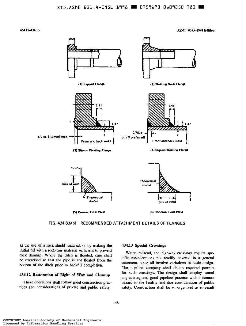
S T D * A S M F - B31-Li-ENGL 177A O 0757b70 Ob07250 T A 3 O
434.11434.13
U
112 in. (13 mm)
ASME B31.4-199% E d i t h
t
max. - I II I Frontandbackweld
(3) Slipon Welding Flange
Size of weld L Theoretical
throat
(5 ) Convex Fillet Weid
4t
0.707 t
I ' Front and back weld (or t if preferred)
(4) Slipon Welding Flange
I Theoretical
throat
Size of weld
(6) Conuve Filkt Weid
FIG. 434.8Mb) RECOMMENDED ATTACHMENT DETAILS OF FLANGES
as the use of a rock shield material, or by making the initial fill with a rock-free material sufficient to prevent rock damage. Where the ditch is flooded, care shall be exercised so that the pipe is not floated from the bottom of the ditch prior to backfill completion.
434.13 Special Crossings
Water, railroad, and highway crossings require spe- cific considerations not readily covered in a general statement, since all involve variations in basic design. The pipeline company shall obtain required permits for such crossings. The design shall employ sound engineering and good pipeline practice with minimum 434*12 Of Right Of Way and 'leanup
These operations shall follow good construction prac- tices and considerations of private and public safety.
hazard to the facility and due consideration of public safety. Construction shall be so organized as to result
48
COPYRIGHT American Society of Mechanical EngineersLicensed by Information Handling ServicesCOPYRIGHT American Society of Mechanical EngineersLicensed by Information Handling Services

STD-ASME B3L-q-ENGL
MME B31.4-1998 Edition
in minimal interference with traffic or the activities of adjacent property owners. Adequate efforts shall be made to determine the location of buried pipelines, utility lines, and other underground structures along and crossing the proposed right of way. The owners of any affected structures shall be given adequate prior notice of the proposed construction so that the owner may make operational preparations and provide a repre- sentative at the crossing.
434.13.1 Water Crossings. Crossings of rivers, streams, lakes, and inland bodies of water are individual problems, and the designer shall investigate composition of bottom, variation in banks, velocity of water, scouring, and special seasonal problems. The designer shall determine whether the crossing is to be underwater, overhead on a suspension bridge, or supported on an adjacent bridge. Continuity of operation and the safety of the general public shall be the controlling factors both in design and in construction. Where required, detailed plans and specifications shall be prepared taking into account these and any special considerations or limitations imposed by the regulatory body involved.
(a) Underwater Construction. Plans and specifica- tions shall describe the position of the line, showing relationship of the pipeline to the natural bottom and the depth below mean low water level when applicable. To meet the conditions set out in para. 434.13.1, heavier wall pipe may be specified. Approach and position of the line in the banks is important, as is the position of the line across the bottom. Special consideration shall be given to depth of cover and other means of protecting the pipeline in the surf zone. Special consideration shall be given to protective coating and the use of concrete jacketing or the application of river weights. Complete inspection shall be provided. Precautions shall be taken during construction to limit stress below the level that would produce buckling or collapse due to out-of-roundness of the completed pipeline.
434.13.2 Overhead Structures. Overhead structures used to suspend pipelines shall be designed and con- structed on the basis of sound engineering and within the restrictions or regulations of the governing body having jurisdiction. Detailed plans and specifications shall be prepared where required and adequate inspec- tion shall be provided to assure complete adherence thereto.
434.13.3 Bridge Attachments. Special requirements are involved in this type of crossing. The use of higher strength lightweight steel pipe, proper design
9LT E
434.13434.15.1
and installation of hangers, and special protection to prevent damage by the elements or bridge and approach traffic shall be considered. Any agreed upon restrictions or precautions shall be contained in the detailed specifi- cations. Inspectors shall assure themselves that these requirements are met.
434.13.4 Railroad and Highway Crossings (a ) The safety of the general public and the preven-
tion of damage to the pipeline by reason of its location are primary considerations. The great variety of such crossings precludes standard design. The construction specifications shall cover the procedure for such cross- ings, based upon the requirements of the specific lo- cation.
(6) Installation of uncased canier pipe is preferred. Installation of carrier pipe, or casing if used, shall be in accordance with API RP 1102. As specified in para. 461.1.2(0, if casing is used, coated carrier pipe shall be independently supported outside each end of the casing and insulated from the casing throughout the cased section, and casing ends shall be sealed using a durable, electrically nonconductive material.
(c) The effective stress due to internal pressure and external loads (including both live and dead loads) in pipe installed under railroads or highways without use of casing shall not exceed 0.90SMYS (specified mini- mum yield strength). Also, cyclic stress components shall be checked for fatigue failure.
434.14 Inland Coastal Water Construction (98)
Plans and specifications shall describe alignment of the pipeline, depth below mean water level, and depth below bottom if ditched. Special consideration shall be given to depth of cover and other means of protecting the pipeline in the surf zone. Consideration shall be given to use of weight coating(s), anchors, or other means of maintaining position of the pipe under antici- pated conditions of buoyance and water motion. Com- plete construction inspection shall be provided. Precau- tions shall be taken during construction to limit stress below the level that would produce buckling or collapse due to out-of-roundness of the completed pipeline.
434.15 Block and isolating Valves
434.15.1 General (98) (a ) Block and isolating valves shall be installed for
limiting hazard and damage from accidental discharge and for facilitating maintenance of the piping system.
(b) Valves shall be at accessible locations, protected from damage or tampering, and suitably supported to
49
COPYRIGHT American Society of Mechanical EngineersLicensed by Information Handling ServicesCOPYRIGHT American Society of Mechanical EngineersLicensed by Information Handling Services

STD-ASME BIL-L i -ENGL 1778 0757b70 Ob07252 85b
434.15.1434.20.1
prevent differential settlement or movement of the attached piping. Where an operating device to open or close the valve is provided, it shall be protected and accessible only to authorized persons.
(c) Submerged valves on pipelines shall be marked or spotted by survey techniques to facilitate quick location when operation is required.
434.15.2 Mainline Valves (a) Mainline block valves shall be installed on the
upstream side of major river crossings and public water supply reservoirs. Either a block or check valve shall be installed on the downstream side of major river crossings and public water supply reservoirs.
(6) A mainline block valve shall be installed at mainline pump stations, and a block or check valve (where applicable to minimize pipeline backflow) shall be installed at other locations appropriate for the terrain features. In industrial, commercial, and residential areas where construction activities pose a particular risk of external damage to the pipeline, provisions shall be made for the appropriate spacing and location of main- line valves consistent with the type of liquids being transported.
(c) A remotely operated mainline block valve shall be provided at remotely controlled pipeline facilities to isolate segments of the pipeline.
(d) On piping systems transporting LPG or liquid anhydrous ammonia, check valves shall be installed where applicable with each block valve to provide automatic blockage of reverse flow in the piping system.
(e) In order to facilitate operational control, limit the duration of an outage, and to expedite repairs, mainline block valves shall be installed at 7.5 mile (12 km) maximum spacing on piping systems trans- porting LPG or liquid anhydrous ammonia in industrial, commercial, and residential areas.
434.15.3 Pump Station, Tank Farm, and Terminai valves
(a) Valves shall be installed on the suction and discharge of pump stations whereby the pump station can be isolated from the pipeline.
(b) Valves shall be installed on lines entering or leaving tank farms or terminals at convenient locations whereby the tank farm or terminal may be isolated from other facilities such as the pipeline, manifolds, or pump stations.
434.16 Connections to Main Lines
Where connections to the main line such as branch lines, jump-overs, relief valves, air vents, etc., are made
ASME B31.4-1998 Edition
to the main line, they shall be made in accordance with para. 404.3.1. When such connections or additions are made to coated lines, all damaged coating shall be removed and replaced with new coating material in accordance with para. 461.1.2(h). This protective coating should include the attachments.
434.17 Scraper Traps
434.17.1 Scraper traps are to be installed as deemed necessary for good operations. All pipe, valves, fittings, closures, and appurtenances shall comply with appro- priate sections of this Code.
434.17.2 Scraper traps on mainline terminations and tied into connection piping or manifolding shall be anchored below ground with adequate concrete anchors when required and suitably supported above ground to prevent transmission of line stresses due to expansion and contraction to connecting facilities.
434.17.3 Scraper trap and its components shall be assembled in accordance with para. 435, and pressure tested to the same limits as the main line. See para. 437.4.
434.18 Line Markers (98)
Adequate pipeline location markers indicating caution for the protection of the pipeline, the public, and persons performing work in the area shall be installed over each line on each side of road, highway, railroad, and stream crossings. Markers in accordance with require- ments of regulatory agencies shall be installed on each side of navigable stream crossings. API RP 1109 shall be used for guidance.
434.19 Corrosion Control
Protection of ferrous pipe and components from external and internal corrosion shall be as prescribed in Chapter VIII.
434.20 Pump Station, Tank Farm, and Terminai
434.20.1 General. All construction work performed on pump stations, tank farms, terminals, equipment installations, piping, and allied facilities shall be done under construction specifications. Such specifications shall cover all phases of the work under contract and shall be in sufficient detail to insure that the requirements of this Code shall be met. Such specifications shall include specific details on soil conditions, foundations and concrete work, steel fabrication and building erec-
Construction
50
COPYRIGHT American Society of Mechanical EngineersLicensed by Information Handling ServicesCOPYRIGHT American Society of Mechanical EngineersLicensed by Information Handling Services

S T D - A S M E B31-4-ENGL 1178 m 0759b70 Ob07253 792 m
ASME B31.4-1998 Edition
tion, piping, welding, equipment and materials, and all construction factors contributing to safety and sound engineering practice.
434.2û.2 Location. Pump stations, tank farms, and terminals should be located on the pipeline's fee or leased property in order to be assured that proper safety precautions may be applied. The pump station, tank farm, or terminal shall be located at such clear distances from adjacent properties not under control of the com- pany as to minimize the communication of fire from structures on adjacent properties. Similar consideration shall be given to its relative location from the station manifolds, tankage, maintenance facilities, personnel housing, etc. Sufficient open space shall be left around the building and manifolds to provide access for mainte- nance equipment and fire fighting equipment. The sta- tion, tank farm, or terminal shall be fenced in such a manner as to minimize trespass, and roadways and gates should be located to give ready access to or egress from the facilities.
434.2û.3 Building Installation. Buildings shall be located and constructed to comply with detailed plans and specifications. The excavation for and installation of foundations and erection of the building shall be done by craftsmen familiar with the respective phase of the work, and all work shall be done in a safe and workmanlike manner. Inspection shall be provided to assure that the requirements of the plans and specifica- tions are met.
434.20.4 Pumping Equipment and Prime Movers. Installation of pumping equipment and prime movers shall be covered by detailed plans and specifications which have taken into account the variables inherent in local soil conditions, utilization, and arrangement of the equipment to provide the optimum in operating ease and maintenance access. Machinery shall be handled and mounted in accordance with recognized good millwright practice and be provided with such protective covers as to prevent damage during construction. Recommenda- tions of installation details provided by manufacturers for auxiliary piping, setting, and aligning shall be considered as minimum requirements.
434.20.5 Pump Station, Tank Farm, and Terminai Piping. All piping, including but not limited to main unit interconnections, manifolds, scraper traps, etc., which can be subject to the mainline pressure shall be constructed in accordance with the welding standards (see para. 434.8), corrosion control requirements (see Chapter VIII), and other practices of this Code.
434.2û.1434.212
434.20.6 Controls and Protective Equipment. Pres- sure controls and protective equipment, including pres- sure limiting devices, regulators, controllers, relief valves, and other safety devices, as shown on the drawings or required by the specifications, shall be installed by competent and skilled workmen. Installation shall be accomplished with careful handling and mini- mum exposure of instruments and devices to inclement weather conditions, dust, or dirt to prevent damage. Also, piping, conduits, or mounting brackets shall not cause the instruments or devices to be distorted or in any strain. Instruments and devices shall be installed so that they can be checked without undue interruptions in operations. After installation, controls and protective equipment shall be tested under conditions approximat- ing actual operations to assure their proper functioning.
434.20.7 Fire Protection. Fire protection when pro- (98) vided shall be in accordance with recommendations in NFPA 30. If the system installed requires the services of fire pumps, their motive power shall be separate from the station power so that their operation shall not be affected by emergency shutdown facilities.
434.21 Storage and Working Tankage
434.21.1 General. All construction work performed on storage and working tankage and allied equipment, piping, and facilities shall be done under construction specifications. Such specifications shall cover all phases of the work under contract, and shall be in sufficient detail to insure that the requirements of the Code shall be met. Such specifications shall include specific details on soil conditions, foundations and concrete work, tank fabrication and erection, piping, welding, equipment and materials, dikes, and all construction factors contrib- uting to safety and sound engineering practice.
434.21.2 Location 1981
(u) Tankage shall be located on the pipeline's fee or leased property in order to assure that proper safety precautions may be applied. Tank facilities shall be located at such clear distances from adjacent properties not under control of the company as to minimize the communication of fire from structures on adjacent properties. Similar consideration shall be given to rela- tive locations between station manifolds, pumping equipment, maintenance facilities, personnel housing, etc. Sufficient open space shall be left around the tankage facilities and associated equipment to provide access for maintenance and fire fighting equipment. The tankage area shall be fenced so as to minimize
COPYRIGHT American Society of Mechanical EngineersLicensed by Information Handling ServicesCOPYRIGHT American Society of Mechanical EngineersLicensed by Information Handling Services

43431.2434242
trespass, and roadways and gates should be located to give ready ingress to and egress from the facilities.
(6) Spacing of tankage shall be governed by the requirements of NFPA 30.
(98) 434.21.3 Tanks and Pipe-Type Storage (u) Tanks for storage or handling crude oil and
liquid petroleum products and liquid alcohols having vapor pressures approximating atmospheric shall be constructed in accordance with API 650, API 12B, API 12D, API 12F, or designed and constructed in accord- ance with accepted good engineering practices.
(b) Tanks for storage or handling liquid petroleum products and liquid alcohols having vapor gage pressures of 0.5 psi (0.035 bar) but not exceeding 15 psi (1 bar) shall be constructed in accordance with API 620.
(c) Tanks used for storage or handling liquids having vapor gage pressures greater than 15 psi (1 bar) shall be designed and constructed in accordance with the design of accredited tank builders and the ASME Boiler and Pressure Vessel Code, Section VIII, Division 1 or Division 2.
(d) Buried pipe-type holders used for storage and handling liquid petroleum, liquid alcohols, or liquid anhydrous ammonia shall be designed and constructed in accordance with the requirements of this Code for pipe and piping components.
434.21.4 Foundations. Tank foundations shall be constructed in accordance with plans and specifications which shall take into account local soil conditions, type of tank, usage, and general location.
(98) 434.21.5 Dikes or Firewdis. "he protection of the pipeline's station, tank farm, terminal, or other facilities from damage by fire from adjacent facilities, as well as the protection of the general public, may dictate the need of dikes or firewalls around tankage or between tankage and station or terminal. Tank dikes or firewalls, where required, shall be constructed to meet the capacity requirements set out in NFTA 30.
434.22 Electrical Instaiiations
(98i 434.22.1 General. Electrical installations for light- ing, power, and control shall be covered by detailed plans and specifications, and installations shall be in accordance with codes applicable to the specific type of circuitry and classification of areas for electrical installation. Inspection shall be provided and all circuitry shall be tested before operation to assure, that the installation was made in workmanlike manner to provide for the continuing safety of personnel and equipment.
ASME B31.4-1998 Edition
installations shall be made in accordance with NFPA 70 and API RP 5ooC.
434.22.2 Care and Handling of Materials. All elec- trical equipment and instruments shall be carefully handled and properly stored or enclosed to prevent damage, deterioration, or contamination during construc- tion. Packaged components are not to be exposed until installation. Equipment susceptible to damage or deterioration by exposure to humidity shall be ade- quately protected by using appropriate means such as plastic film enclosures, desiccants, or electric heating.
434.22.3 installation. The installation of electrical materials shall be made by qualified personnel familiar with details of electrical aspects and code requirements for such installation. At all times care shall be exercised to prevent damage to the insulation of cable and wiring. All partial installations shall be protected from damage during construction. The installation design and specifi- cations shall give consideration to the need for dust- and/or moisture-proof enclosures for such special gear as relays, small switches, and electronic components. In no case shall the frames of electric motors or other grounded electrical equipment be used as the ground connection for electrical welding.
434.23 Liquid Metering
434.23.1 Positive displacement meters, turbine me- ters, or equivalent liquid measuring devices and their proving facilities shall be designed and installed in accordance with the API Manual of Petroleum Measure- ment Standards.
434.23.2 Provisions shall be made to permit access to these facilities by authorized personnel only.
434.23.3 Assembly of the metering facility compo- nents shall be in accordance with para. 435.
434.24 Liquid Strainers and Filters
434.24.1 Strainers and filters shall be designed to the same pressure limitations and subjected to the same test pressures as the piping system in which they are installed, and supported in such a manner as to prevent undue loading to the connecting piping system.
434.24.2 Installation and design shall provide for ease of maintenance and servicing without interference with the station operation.
52
COPYRIGHT American Society of Mechanical EngineersLicensed by Information Handling ServicesCOPYRIGHT American Society of Mechanical EngineersLicensed by Information Handling Services

ASME B31.4a-2001 434.24.3-435.5.2
434.24.3 The filtering medium should be of such retention size and capacity as to fully protect the facilities against the intrusion of harmful foreign sub- s tances.
434.24.4 Assembly of strainers or filters and their components shall be in accordance with para. 435.
435 ASSEMBLY OF PIPING COMPONENTS
435.1 General
O The assembly of the various piping components, . . ~
whether done in a shop or as a field erection, shall be done so that the completely erected piping conforms with the requirements of this Code and with the specific requirements of the engineering design.
435.2 Bolting Procedure
435.2.1 All flanged joints shall be fitted up so that the gasket contact faces bear uniformly on the gasket, and made up with uniform bolt stress.
435.2.2 In bolting gasketed flanged joints, the gasket shall be properly compressed in accordance with the design principles applicable to the type of gasket used.
AI1 bolts or studs shall extend completely 435.2.3 through their nuts.
435.3 Pumping Unit Piping
435.3.1 Piping to main pumping units shall be so designed and supported that when assembled to the pump flanges and valves it should be relatively free of stress and should not add stress or load to the pump frame.
435.3.2 The design and assembly shall take into account the forces of expansion and contraction to minimize their effect within the assembly.
e A01 435.3.3 All valves and fittings on pumping units
shall carry the same pressure ratings as required for line operating pressures.
435.3.4 Welding shall be in accordance with para. 434.8 of the Code.
435.3.5 Bolting shall be in accordance with para. 435.2.
435.4 Manifolds
435.4.1 All components within a manifold assembly, including valves, flanges, fittings, headers, and special assemblies, shall withstand the operating pressures and specified loadings for the specific service piping to which it is connected.
435.4.2 Meter banks, prover loops, and scraper traps shall be subject to the same assembly requirements as manifolds.
435.4.3 Manifold headers with multiple outlets shall have outlets designed as covered in paras. 404.3.1(b) and 404.3. ](e) and illustrated in Figs. 404.3.l(b)(3) and 404.3. I (d)(2), respectively. Assembly may be with the use of jigs to assure alignment of outlets and flanges with other components. The fabricated unit shall be stress relieved before removal from the jig.
435.4.4 Manifold headers assembled from wrought tees, fittings, and flanges may be assembled with jigs to assure alignment of components. Stress relieving should be considered.
435.4.5 All welding on manifolds and headers shall conforin to para. 434.8.
435.4.6 Final assembly of all components shall minimize locked-in stresses. The entire assembly shall be adequately supported to provide minimum unbalance and vibration.
435.5 Auxiliary Liquid Petroleum, Carbon Dioxide, Liquid Anhydrous Ammonia, or Liquid Alcohol Piping
435.5.1 All auxiliary piping between main units and auxiliary components shall be assembled in a work- manlike manner and in accordance with the applica- ble code.
435.5.2 Ail welded auxiliary lines shall be assembled in accordance with the requirements of this Code with special provisions as required for assembly to minimize locked-in stress, and for adequate support or restraint to minimize vibration.
53
COPYRIGHT American Society of Mechanical EngineersLicensed by Information Handling ServicesCOPYRIGHT American Society of Mechanical EngineersLicensed by Information Handling Services

STD-ASME B3L.q-ENGL 1778 0757b70 Ub0325b 4 T L
ASME B31.4-1998 Edition 43ó4365.1
CHAPTER VI INSPECTION AND TESTING
436 ENSPECTION
436.1 General
Construction inspection provisions for pipelines and related facilities shall be adequate to assure compliance with the material, construction, welding, assembly, and testing requirements of this Code.
4362 Qualification of Inspectors
Inspection personnel shall be qualified by training and experience. Such personnel shall be capable of performing the following inspection services:
right of way and grading; ditching; line up and pipe surface inspection; welding; coating; tie-in and lowering; -- backfilling and clean up; pressure testing; special services for testing and inspection of
facilities, such as station construction, river crossings, electrical installation, radiography, corrosion control, etc., as may be required.
436.5 Type and Extent of Examination Required
(98) 436.5.1 visual (a) Material
(1) All piping components shall be visually in- spected to insure that no mechanical damage has oc- curred during shipment and handling prior to being connected into the piping system.
(2) All pipe shall be visually inspected to discover any defects as described in paras. 434.5 and 434.8.7.
(3) On systems where pipe is telescoped by grade, wall thickness, or both, particular care shall be taken to insure proper placement of pipe. Permanent records shall be kept showing the location as installed of each grade, wall thickness, type, specification, and manufacturer of the pipe.
(b) Construction
( I ) Visual inspection for detection of surface de- fects in the pipe shall be provided for each job just ahead of any coating operation and during the lowering- in and backfill operation.
(2) The pipe swabbing operation shall be inspected for thoroughness to provide a clean surface inside the pipe.
(3) Before welding, the pipe shall be examined for damage-free bevels and proper alignment of the joint.
(4) The stringer bead shall be inspected, particu- larly for cracks, before subsequent beads are applied.
(5) The completed weld shall be cleaned and inspected prior to coating operations, and irregularities that could protrude through the pipe coating shall be removed.
(6) When the pipe is coated, inspection shall be made to determìne that the coating machine does not cause harmful gouges or grooves in the pipe surface.
(7) Lacerations of the pipe coating shall be in- spected prior to repair of coating to see if the pipe surface has been damaged. Damaged coating and pipe shall be repaired before the pipe is lowered in the ditch.
(8) All repairs, changes, or replacements shall be inspected before they are covered up.
(9) The condition of the ditch shall be inspected before the pipe is lowered in to assure proper protection of pipe and coating. For underwater crossings the condition of the ditch and fit of the pipe to the ditch shall be inspected when feasible.
(IO) The fit of the pipe to ditch shall be inspected before the backfilling operations.
(I I) The backfilling operations shall be inspected for quality and compaction of backfill, placement of material for the control of erosion, and possible damage to the pipe coatings.
(12) Cased crossings shall be inspected during in- stallation to determine that the carrier pipe is supported, sealed, and insulated from the casing.
(13) River crossings shall have thorough inspection, and shall be surveyed and profiled after construction.
(14) All piping components other than pipe shall be inspected to insure damage-free condition and proper installation.
55
COPYRIGHT American Society of Mechanical EngineersLicensed by Information Handling ServicesCOPYRIGHT American Society of Mechanical EngineersLicensed by Information Handling Services

STD-ASME B31-4-EMGL L71d II 0759b70 üb07257 338 m
436.5.2-437.4.1
436.5.2 Supplementary Types of Examination (a) Testing of field and shop welds shall be made
(b) Radiographic inspection of welds shall be per-
(c) Coated pipe shall be inspected in accordance
in accordance with para. 434.8.5.
formed in accordance with para. 434.8.5.
with para. 461.1.2.
436.6 Repair of Defects
436.6.1 Defects of fabricated items and in pipe wall shall be repaired or eliminated in accordance with para. 434.5.
436.6.2 Welding defects shall be repaired in accord- ance with para. 434.8.1.
436.6.3 Holidays or other damage to coating shall be repaired in accordance with para. 461.1.2.
437 TESTING
437.1 General
(a ) In order to meet requirements of this Code, it is necessary that tests be made upon the completed system and upon component parts of the finished system. When reference in this Code is made to tests or portions of tests described in other codes and specifications, they shall be considered as a part of this Code.
(6) Should leaks occur on tests, the line section or component part shall be repaired or replaced and retested in accordance with this Code.
437.1.3 Testing of Fabricated Items (a) Fabricated items such as scraper traps, manifolds,
volume chambers, etc., shall be hydrostatically tested to limits equal to or greater than those required of the completed system. This test may be conducted separately or as a part of the completed system.
(6) In testing fabricated items before installation, the applicable paragraphs of specifications listed in Table 423.1 shall apply.
437.1.4 Testing After New Construction (a ) Systems or Parts of Systems
(1) All liquid transportation piping systems within the scope of this Code, regardless of stress, shall be tested after construction. Carbon dioxide systems shall be hydrostatically tested.
(2) Systems to be operated at a hoop stress of more than 20% of the specified minimum yield strength
M M E B31.4-1998 E d i t h
of the pipe shall be hydrostatically tested in accordance with para. 437.4.1.
(3) Systems to be operated at a hoop stress of 20% or less of specified minimum yield strength of the pipe may be subjected to a leak test in accordance with para. 437.4.3 in lieu of the hydrostatic test specified in para. 437.4.1.
(4) When testing piping, in no case shall the test pressure exceed that stipulated in the standards of material specifications (except pipe) incorporated in this Code by reference and listed in Table 423.1 for the weakest element in the system, or portion of system, being tested.
(5) Equipment not to be subjected to test pressure shall be disconnected from the piping or otherwise isolated. Valves may be used if valve, including closing mechanism, is suitable for the test pressure.
(6) Testing Tie-lns. Because it is sometimes neces- sary to divide a pipeline into test sections and install test heads, connecting piping, and other necessary appur- tenances for testing, or to install a pretested replacement section, it is not required that tie-in welds be tested; however, tie-in welds and girth welds joining lengths of pretested pipe shall be inspected by radiographic or other accepted nondestructive methods in accordance with para. 434.8.5(a)(4) if system is not pressure tested after tie-in. After such inspection, the joint shall be coated and inspected in accordance with para. 461.1.2 before backfilling.
(c) Testing Controls and Protective Equipment. All controls and protective equipment, including pressure limiting devices, regulators, controllers, relief valves, and other safety devices, shall be tested to determine that they are in good mechanical condition; of adequate capacity, effectiveness, and reliability of operation for the service in which they are employed; functioning at the correct pressure; and properly installed and protected from foreign materials or other conditions that might prevent proper operation.
437.4 Test Pressure
437.4.1 Hydrostatic Testing of Internal Pressure Piping
(a) Portions of piping systems to be operated at a hoop stress of more than 20% of the specified minimum yield strength of the pipe shall be subjected at any point to a hydrostatic proof test equivalent to not less than 1.25 times the internal design pressure at that point (see para. 401.2.2) for not less than 4 hr. When lines are tested at pressures that develop a hoop stress, based on nominal wall thickness, in excess of 90% of
56
COPYRIGHT American Society of Mechanical EngineersLicensed by Information Handling ServicesCOPYRIGHT American Society of Mechanical EngineersLicensed by Information Handling Services

ASME B31.4-1998 Edition 437.4.1437.6.4
the specified minimum yield strength of the pipe, special care shall be used to prevent overstrain of the pipe.
(I) Those portions of piping systems where all of the pressured components are visually inspected during the proof test to determine that there is no leakage require no further test. This can include lengths of pipe that are pretested for use as replacement sections.
(2) On those portions of piping systems not visu- ally inspected while under test, the proof test shall be followed by a reduced pressure leak test equivalent to not less than 1.1 times the internal design pressure for not less than 4 hr.
(6) API RP 1110 may be used for guidance for the hydrostatic test.
(c) The hydrostatic test shall be conducted with water, except liquid petroleum that does not vaporize rapidly may be used provided:
( I ) the pipeline section under test is not offshore and is outside of cities and other populated areas, and each building within 300 ft (90 m) of the test section is unoccupied while the test pressure is equal to or greater than a pressure which produces a hoop stress of 50% of the specific minimum yield strength of the pipe;
(2) the test section is kept under surveillance by regular patrols during test; and
(3) communication is maintained along the test section.
(d) If the testing medium in the system will be subject to thermal expansion during the test, provisions shall be made for relief of excess pressure. Effects of temperature changes shall be taken into account when interpretations are made of recorded test pressures.
(e) After completion of the hydrostatic test, it is important in cold weather that the lines, valves, and fittings be drained completely of any water to avoid damage due to freezing.
íJ Carbon dioxide pipelines, valves, and fittings shall be dewatered and dried prior to placing in service to prevent the possibility of forming a corrosive com- pound from carbon dioxide and water.
437.4.3 Leak Testing. A 1 hr hydrostatic or pneu- matic leak test may be used for piping systems to be operated at a hoop stress of 20% or less of the specified minimum yield strength of the pipe. The hydrostatic test pressure shall be not less than 1.25 times the internal design pressure. The pneumatic test gage pressure shall be 100 psi (7 bar) or that pressure which would produce a nominal hoop stress of 25% of the specified minimum yield strength of the pipe, whichever is less.
437.6 Qualification Tests
Where tests are required by other sections of this Code, the following procedures shall be used.
437.6.1 Visual Examination. Used or new pipe to be laid shall be visually examined in accordance with para. 436.5.1.
437.6.2 Bending Properties
(a) For pipe of unknown specification or ASTM A 120, bending properties are required if minimum yield strength used for design is above 24,000 psi (165 MPa), and after type of joint has been identified in accordance with para. 437.6.4. For pipe NPS 2 and smaller, bending test shall meet the requirements of ASTM A 53 or API 5L. For pipe larger than NPS 2 in nominal diameter, flattening tests shall meet the requirements in ASTM A 53, API 5L, or API 5LU.
(6) The number of tests required to determine bend- ing properties shall be the same as required i n para. 437.6.6 to determine yield strength.
437.6.3 Determination of Wall Thickness. When the nominal wall thickness is not known, it shall be determined by measuring the thickness at quarter points on one end of each piece of pipe. If the lot of pipe is known to be of uniform grade, size, and nominal thickness, measurement shall be made on not less than 5% of the individual lengths, but not less than 10 lengths; thickness of the other lengths may be verified by applying a gage set to the minimum thickness. Following such measurement, the nominal wall thick- ness shall be taken as the next nominal wall thickness below the average of all the measurements taken, but in no case greater than 1.14 times the least measured thickness for all pipe under NPS 20, and no greater than 1.11 times the least measured thickness for all pipe NPS 20 and larger.
437.6.4 Determination of Weld Joint Factor. If the type of longitudinal or spiral weld joint is known, the corresponding weld joint factor (Table 402.4.3) may be used. Otherwise, as noted in Table 402.4.3, the factor E shall not exceed 0.60 for pipe NPS 4 and smaller, or 0.80 for pipe over NPS 4.
57
COPYRIGHT American Society of Mechanical EngineersLicensed by Information Handling ServicesCOPYRIGHT American Society of Mechanical EngineersLicensed by Information Handling Services

S T D = A S M E B3L-Li-ENGL L19A 0759b7U flbI19257 L O O
437.6.-37.7
437.6.5 Weldability. For steel pipe of unknown spec- ification, weldability shall be determined as follows. A qualified welder shall make a girth weld in the pipe. This weld shall be tested in accordance with the require- ments of para. 434.8.5. The qualifying weld shall be made under the most severe conditions under which welding will be permitted in the field and using the same procedure as to be used in the field. The pipe shall be considered weldable if the requirements set forth in para. 434.8.5 are met. At least one such test weld shall be made for each number of lengths to be used as listed below.
Minimum Number of Test Welds
Nominal Pipe Number of Lengths size per Test
Less than 6 6 through 12 Larger than 12
400 200 100
All test specimens shall be selected at random.
437.6.6 Determination of Yield Strength. When the specified minimum yield strength, minimum tensile strength, or minimum percent of elongation of pipe is unknown, the tensile properties may be established as fol10 ws .
Perform all tensile tests prescribed by API 5L or 5LU, except that the minimum number of such tests shall be as follows.
ASME B31.4-1998 Edition
Nominal Pipe Number of Lengths SiZe per Test
Lessthan6 200
Larger than 12 50 6 through 12 100
All test specimens shall be selected at random.
437.6.7 Minimum Yield Strength Value. For pipe of unknown specification, the minimum yield strength may be determined as follows.
Average the value of all yield strength tests for a test lot. The minimum yield strength shall then be taken as the lesser of the following:
(a) 80% of the average value of the yield strength tests;
(b) the minimum value of any yield strength test, except that in no case shall this value be taken as greater than 52,000 psi (358 MPa);
(c) 24,000 psi (165 MPa) if the average yield-tensile ratio exceeds 0.85.
437.7 Records
A record shall be maintained in the files of the operating company relative to design, construction, and testing of each mainline within the scope of this Code. These records shall include material specifications; route maps and alignments sheets for 'as-built' condition; location of each pipe size, grade, wall thickness, type of seam (if any), and manufacturer; coatings; test data; and, for carbon dioxide pipelines, toughness require- ments. These records shall be kept for the life of the facility. See para. 436.5.l(a)(3).
58
COPYRIGHT American Society of Mechanical EngineersLicensed by Information Handling ServicesCOPYRIGHT American Society of Mechanical EngineersLicensed by Information Handling Services
ASME B31.4a-2001 450-450.2
CHAPTER VI1 OPERATION AND MAINTENANCE PROCEDURES
450 OPERATION AND MAINTENANCE PROCEDURES AFFECTING THE SAFETY OF LIQUID TRANSPORTATION PIPING SYSTEMS
450.1 General
(a) It is not possible to prescribe in this Code a detailed set of operating and maintenance procedures that will encompass all cases. It is possible, however, for each operating company to develop operating and maintenance procedures based on the provisions of this Code, and the company’s experience and knowledge of its facilities and conditions under which they are operated, which will be adequate from the standpoint of public safety.
(b) The methods and procedures set forth herein serve as a general guide, but do not relieve the individual or operating company from the responsibility for prudent action that current particular circumstances make ad- visable.
(c) It must be recognized that local conditions (such as the effects of temperature, characteristics of the line contents, and topography) will have considerable bearing on the approach to any particular maintenance and repair job.
(ú) Suitable safety equipment shall be available for personnel use at all work areas and operating facilities where liquid anhydrous ammonia is transported. Such safety equipment shall include at least the following:
( I ) full face gas mask with anhydrous ammonia refill canisters;
(2) independently supplied air mask; (3) tight-fitting goggles or full face shield; (4 ) protective gloves; (5) protective boots; (6) protective slicker and/or protective pants and
jacket; (7) easily accessible shower and/or at least 50 gal
(190 liters) of clean water in an open top container. Personnel shall be instructed in effective use of
masks and limited shelf life of refill canisters. Protective
o
@
clothing shall be of rubber fabric or other ammonia impervious material.
450.2 Operation and Maintenance Plans and Procedures
Each operating company having a transportation pip- ing system within the scope of this Code shall:
(a ) have written detailed plans and training programs for employees covering operating and maintenance pro- cedures for the transportation piping system during normal operations and maintenance in accordance with the purpose of this Code; essential features recom- mended for inclusion in the plans for specific portions of the system are given in paras. 451 and 452.
(b) have a plan for external and internal corrosion control of new and existing piping systems, including requirements and procedures prescribed in para. 453 and Chapter VIII;
(c) have a written Emergency Plan as indicated in para. 454 for implementation in the event of system failures, accidents, or other emergencies; train appro- priate operating and maintenance employees with regard to applicable portions of the plan, and establish liaison with appropriate public officials with respect to the plan;
(ú) have a plan for reviewing changes in conditions affecting the integrity and safety of the piping system, including provisions for periodic patrolling and reporting of construction activity and changes in conditions, especially in industrial, commercial, and residential areas and at river, railroad, and highway crossings, in order to consider the possibility of providing additional protection to prevent damage to the pipeline in accord- ance with para. 402.1;
( e ) establish liaison with local authorities who issue construction permits in urban areas to prevent accidents caused by excavators;
(f) establish procedures to analyze all failures and accidents for the purpose of determining the cause and to minimize the possibility of recurrence;
(g) maintain necessary maps and records to properly administer the plans and procedures, including records listed in para. 455;
59
COPYRIGHT American Society of Mechanical EngineersLicensed by Information Handling ServicesCOPYRIGHT American Society of Mechanical EngineersLicensed by Information Handling Services

450.2-451.6.1 ASME B31.4a-2001
(h) have procedures for abandoning piping systems, including the requirements in para. 457;
(i) in establishing plans and procedures, give particu- lar attention to those portions of the system presenting the greatest hazard to the public in the event of emergen- cies or because of construction or extraordinary mainte- nance requirements;
( j) operate and maintain its piping system in confor- mance with these plans and procedures;
( k ) modify the plans and procedures from time to time as experience dictates and as exposure of the system to the public and changes in operating conditions require.
451 PIPELINE OPERATION AND MAINTENANCE
451.1 Operating Pressure
(a) Care shall be exercised to assure that at any point in the piping system the maximum steady state operating pressure and static head pressure with the line in a static condition do not exceed at that point the internal design pressure and pressure ratings for the components used as specified in para. 402.2.3, and that the levei of pressure rise due to surges and other variations from normal operation does not exceed the internal design pressure at any point in the piping system and equipment by more than 10% as specified in para. 402.2.4.
(b) A piping system shall be qualified for a higher operating pressure when the higher operating pressure will produce a hoop stress of more than 20% of the specified minimum yield strength of the pipe in accordance with para. 456.
(c) If a piping system is derated to a lower operating pressure in lieu of repair or replacement, the new maximum steady state operating pressure shall be deter- mined in accordance with para. 451.7.
(d) For existing systems utilizing materials produced under discontinued or superseded standards or specifica- tions, the internal design pressure shall be determined using the allowable stress and design criteria listed in the issue of the applicable code or specification in effect at the time of the original construction.
451.2 Communications
A communications facility shall be maintained to assure safe pipeline operations under both normal and emergency conditions.
451.3 Markers
(a) Markers shall be installed over each line on each side of road, highway, railroad, and stream crossings to properly locate and identify the system. Markers are not required for pipelines offshore.
(b) Pipeline markers at crossings, aerial markers when used, and other signs shall be maintained so as to indicate the location of the line. These markers shall show the name of the operating company, and, where possible, an emergency telephone contact. Additional pipeline markers shall be installed along the line in areas of development and growth to protect the system from encroachment. API RP 1109 shall be used for guidance.
451.4 Right of Way Maintenance
(a) The right of way should be maintained so as to have clear visibility and to give reasonable access to maintenance crews.
(b) Access shall be maintained to valve locations. (c) Diversion ditches or dikes shall be maintained
where needed to protect against washouts of the line and erosion of the landowner’s property.
451.5 Patrolling
(a) Each operating company shall maintain a periodic pipeline patrol program to observe surface conditions on and adjacent to the pipeline right of way, indication of leaks, construction activity other than that performed by the company, and any other factors affecting the safety and operation of the pipeline. Special attention shall be given to such activities as road building, ditch cleanouts, excavations, and like encroachments to the pipeline system. Patrols shall be made at intervals not exceeding 2 weeks, except that piping systems transporting LPG or liquid anhydrous ammonia shall be patrolled at intervals not exceeding 1 week in industrial, commercial, or residential areas.
(b) Underwater crossings shall be inspected periodi- cally for sufficiency of cover, accumulation of debris, or for any other condition affecting the safety and security of the crossings, and at any time it is felt that the crossings are in danger as a result of floods, storms, or suspected mechanical damage.
451.6 Pipeline Repairs
451.6.1 General (98) (a) Repairs shall be covered by a maintenance plan A01
[see para. 450.2(a)] and shall be performed under e 60
COPYRIGHT American Society of Mechanical EngineersLicensed by Information Handling ServicesCOPYRIGHT American Society of Mechanical EngineersLicensed by Information Handling Services

451.6.1-451.6.2 ASME B31.4a-2001
0 qualified supervision by trained personnel aware of and familiar with the hazards to public safety, utilizing strategically located equipment and repair materials. The maintenance plan shall consider the appropriate information contained in API Publ. 2200, API Pub. 2201, API Standard 1 104, and API RP 1 11 1. It is essential that all personnel working on pipeline repairs understand the need for careful planning of the job, be briefed as to the procedure to be followed in accomplishing the repairs, and follow precautionary measures and procedures outlined in API Publ. 2200. Personnel working on repairs to pipelines handling LPG, carbon dioxide, liquid alcohol, or liquid anhydrous ammonia shall also be informed on the specific proper- ties, characteristics, and potential hazards associated with those liquids, precautions to be taken following detection of a leak, and safety repair procedures set forth for LPG pipelines in API Publ. 2200. Approvals, procedures, and special considerations described in API Publ. 2201 shall be observed for welding, as well as making hot taps on pipelines, vessels, or tanks which are under pressure. Piping in the vicinity of any repair shall be adequately supported during and after the repair.
(b) If an inert fluid is used to temporarily displace the liquid in a pipeline system for the purpose of a repair, a detailed written procedure shall be required. Because the potential energy of a gas presents special concerns, this procedure shall address, as a minimum, the factors related to the use of\ an inert gas:
(I) maximum flow rate; (2) pressure; (3) injection temperature; ( 4 ) inert gas disposal; (5) safety procedures.
The procedure shall be followed under the supervision required in para. 45 1.6.1 (a).
(98) 451.6.2 Disposition of Defects (a) Limits and Dispositions of Imperfections
(I) Gouges and grooves having a depth greater than 12'/2% of the nominal wall thickness shall be removed or repaired.
(2) Dents meeting any of the following conditions shall be removed or repaired:
(a) dents which affect the pipe curvature at the pipe seam or at any girth weld;
(6) dents containing a scratch, gouge, or groove; or
(c) dents exceeding a depth of y4 in. (6 mm) in pipe NPS 4 and smaller, or 6% of the nominal pipe diameter in sizes greater than NPS 4.
AO 1
O (3) All arc burns shall be removed ,or repaired.
(4 ) All cracks shall be removed or repaired. (5) All welds found to have defects as set forth
in para. 434.8.5(b) or in the appropriate pipe specifica- tion shall be removed or repaired.
(6) General Corrosion. Pipe shall be replaced, or repaired if the area is small, or operated at a reduced pressure (see para. 451.7) if general corrosion has reduced the wall thickness to less than the design thickness calculated in accordance with para. 404.1.2 decreased by an amount equal to the manufacturing tolerance applicable to the pipe or component.
(7) Localized Corrosion Pitting. Pipe shall be repaired, replaced, or operated at a reduced pressure (see para. 451.7) if localized corrosion pitting has reduced the wall thickness to less than the design thickness calculated in accordance with para. 404.1.2 decreased by an amount equal to the manufacturing tolerance applicable to the pipe or component. This applies if the length of the pitted area is greater than permitted by the equation shown below. The following method applies only when the depth of the corrosion pit is less than 80% of the nominal wall thickness of the pipe. This method shall not be used to evaluate corrosion concentrated in electric resistance welded seams (ERW), electric induction welded seams or elec- tric flash-welded seams, nor shall it be used to evaluate corrosion-caused metal loss which is circumferentially oriented along or in a girth weld or its heat-affected zone. The method may be used, however, to evaluate the longitudinal profile of corrosion-caused metal loss which crosses a girth weld or impinges on a submerged arc welded seam. The corroded area must be clean to bare metal. Care shall be taken in cleaning corroded areas of a pressurized pipeline when the degree of corrosion is significant.
L = 1.12B f i where
L = i&iximum allowable longitudinal extent of the corroded area as shown in Fig. 451.6.2(a)(7), in. (mm)
B = a value not to exceed 4.0 which may be determined from the above equation or Fig. 45 1.6.2(a)(7)
D = nominal outside diameter of the pipe, in. (mm) t,, = nominal wall thickness of the pipe, in. (mm) c = maximum depth of the corroded area, in. (mm)
61
COPYRIGHT American Society of Mechanical EngineersLicensed by Information Handling ServicesCOPYRIGHT American Society of Mechanical EngineersLicensed by Information Handling Services

451.6.2 ASME B31.4a-2001
Longitudinal axis of corroded areas -
1 i
4
3
rg
2
1
O O 0.2 0.4 0.6 0.8
C/t ,
FIG. 451.6.2(a)(7) PARAMETERS USED I N
AREAS ANALYSIS OF THE STRENGTH OF CORRODED
(8) Areas where grinding has reduced the re- maining wall thickness to less than the design thickness calculated in accordance with para. 404.1.2 decreased by an amount equal to the manufacturing tolerance applicable to the pipe or component, may be analyzed the same as localized corrosion pitting [see para. 451.6.2(a)(7)] to determine if ground areas need to be replaced, repaired, or the operating pressure reduced
(see para. 451.7). ASME B31G may be used for guidance.
(9) All pipe containing leaks shall be removed or repaired.
(b ) Allowable Pipeline Repairs ( I ) If practical, the pipeline should be taken out
of service and repaired by cutting out a cylindrical piece of pipe containing the defect and replacing the same with pipe meeting the requirements of para. 401.2.2 and having a length of not less than one-half diameter.
(2) If not practical to take the pipeline out of service, repairs may be made by the installation of a full encirclement welded or mechanically applied split sleeve in accordance with para. 45 1.6.2(c).
(a ) For repairs of dents, either a hardenable filler material such as epoxy shall be used to f i l l the void between the sleeve and the pipe to restore the original contour of the pipe, or the carrier pipe shall be tapped through the sleeve or other means provided to equalize the internal pressures of the carrier pipe and the sleeve.
(6) For repairs to nonleaking cracks in materiais that might be expected to behave in a brittle manner (e.g., a seam defect in a low-frequency welded ERW seam), an appropriately-designed fitting shall be installed on the sleeve through which the sleeve and carrier pipe will be tapped to equalize the internai pressures of the carrier pipe and the sleeve.
(3) If not practical to take the pipeline out of service, defects may be removed by grinding or hot tapping. When grinding, the ground areas shall be smoothly contoured and be in accordance with para. 45 i .6.2(a)(8). When hot tapping, the portion of piping containing the defect shall be completely removed.
(4) If not practical to take the pipeline out of service, minor leaks and small corroded areas, except for cracks, may be repaired by the installation of a patch or welded fitting i n accordance with paras. 45 1.6.2(c)(5) and (8). Pipe containing arc burns, grooves, and gouges may be repaired with patches or welded fitting if the arc burn or notch is removed by grinding.
(5) If not practical to take the pipeline out of service, defects in welds produced with a filler metal, small corroded areas, gouges, grooves, and arc burns may be repaired by depositing weld metal in accordance with para. 45 1.6.2(~)(9). Weld imperfections, arc burns, gouges, and grooves shall be removed by grinding prior to depositing the weld filler metal.
(6) If not practical to take the pipeline out of
62
COPYRIGHT American Society of Mechanical EngineersLicensed by Information Handling ServicesCOPYRIGHT American Society of Mechanical EngineersLicensed by Information Handling Services
ASME B31.4a-2081 451.6.2
service, nonleaking corroded areas may be repaired by installation of a fully welded, partial encirclement half sole in accordance with para. 45 1.6.2(c)( 13).
(7) If not practical to take the pipeline out of service, nonleaking corroded areas may be repaired by installation of a mechanically applied composite material wrap used to reinforce the pipeline in accordance with para. 451.6.2(~)(14).
(c) Repair Methods (I) All repair weld procedures and all welders
performing repair work shall be qualified in accordance with para. 434.8.3 or API RP 1107. The welders shall also be familiar with safety precautions and other problems associated with cutting and welding on pipe that contains or has contained liquids within the scope of this Code. Cutting and welding shall commence only after compliance with para. 434.8.1(c).
(2) The qualification test for welding procedures to be used on pipe containing a liquid shall consider the cooling effects of the pipe contents on the soundness and physical properties of the weld. Welding procedures on pipe not containing liquid shall be qualified in accordance with para. 434.8.3.
(3) Materials used for pipeline repair shall be in accordance with at least one of the specifications or standards listed in Table 423.1, or as otherwise required by this Code.
(4) Temporary repairs may be necessitated for operating purposes and shall be made in a safe manner. Such temporary repairs shall be made permanent or replaced in a permanent manner as described herein as soon as practical.
(5) Welded patches shall have rounded corners and a maximum dimension of 6 in. (150 mm) along the pipe axis. The patch material shall be of a similar or higher grade with a wall thickness similar to the pipe being repaired. Patches shall be limited to pipe sizes NPS i2 and less and conforming to API 5L, Grade X42 and lower. Patches shall be attached by fillet welds. Insert patching is prohibited. Special consid- eration shall be given to minimize stress concentrations resulting from the repair.
(6) Full encirclement welded split sleeves installed to repair leaks or otherwise to contain internal pressure shall have a design pressure of not less than the pipe being repaired and shall be fully welded, both circumferentially and longitudinally. Length of full en- circlement split sleeves shall not be less than 4 in. (100 mm). If the sleeve is thicker than the pipe being repaired, the circumferential ends shall be chamfered (at approximately 45 deg.) down to the thickness of
the pipe. For full encirclement split sleeves installed for repair by reinforcement only and not internal pressure containment, circumferential welding is optional. Spe- cial consideration shall be given to minimize stress concentrations resulting from the repair.
(7) Mechanically applied full encirclement repair fittings shall meet the design requirements of paras. 401.2 and 418.
(8) Welded fittings used to cover pipeline defects shall not exceed NPS 3 and shall have a design pressure of not less than the pipe being repaired.
(9) For repairs involving only deposition of a weld filler metal, welding processes shall be in accordance with the requirements of the appropriate pipe specifica- tion for the grade and type being repaired. Welding procedure qualifications shall be in accordance with para. 45 1.6.2(~)(2).
(10) Where repairs are made to a coated pipe, all damaged coating shall be removed and new coating applied in accordance with para. 461.1.2. Replacement pieces of pipe, welded patches, and full encirclement welded split sleeves used in making repairs shall also be coated when installed in a coated line.
( I I ) Pipe containing liquid shall be examined to determine that the material is sound and of adequate thickness in the areas to be affected by grinding, welding, cutting, or hot tapping operations.
(12) If the pipeline is not taken out of service, the operating pressure shall be reduced to a level which will provide safety during the repair operations.
(13) Fully welded partial encirclement half soles may be used to repair corroded areas only on pipe and shall not be used to repair leaks, gouges, dents, or other defects. The use of half soles shall be limited to pipe sizes NPS 12 or less and may only be used on pipe made prior to 1942 with a specified minimum yield strength not exceeding 40,000 psi (276 MPa). The half sole material shall be of a similar or higher grade with a wall thickness not less than 87.5% or more than 125% of that of the pipe being repaired. Half soles shall have rounded corners and a maximum length of 10 ft (3 m) along the pipe axis. Half soles shall not be used across girth welds and the minimum clearance between the end of half soles or the ends of half soles and girth welds shall be 2 in. Combinations of a half sole and patches shall not be used in parallel around a given circumference. To ensure optimum performance of half soies, the annular space between the corroded pipe and the half sole may be filled with a hardenable filler material such as epoxy. Special consideration shall be given to ensuring a close fit
63
COPYRIGHT American Society of Mechanical EngineersLicensed by Information Handling ServicesCOPYRIGHT American Society of Mechanical EngineersLicensed by Information Handling Services

451.6.2-451.9 ASME B31.4a-2001
between the edges of the half sole and the pipe being repaired and to minimizing stress concentrations re- sulting from the repair.
(14) Mechanically applied composite material wrap may be used to reinforce the pipeline provided that design and installation methods are proven for the intended service prior to application. The user is cau- tioned that a qualified written procedure performed by trained personnel is a requirement and records shall be retained in accordance with para. 455.
451.6.3 Testing Repairs to Pipelines Operating at a Hoop Stress of More Than 20% of the Specified Minimum Yield Strength of the Pipe
(a ) Testing of Replacement Pipe Sections. When a scheduled repair to a pipeline is made by cutting out a section of the pipe as a cylinder and replacing i t with another section of pipe, the replacement section of pipe shall be subjected to a pressure test. The replacement section of pipe shall be tested as required for a new pipeline in accordance with para. 437.4.1. The tests may be made on the pipe prior to installation
- provided radiographic or other acceptable nondestructive tests (visual inspection excepted) are made on all tie- in butt welds after installation.
(b) Examination of Repair Welds. Welds made during pipeline repairs shall be examined by accepted non-destructive methods or visually examined by a qualified inspector.
451.7 Derating a Pipeline to a Lower Operating Pressure
(a ) Corroded pipe or pipe containing areas repaired by grinding may be derated to a lower operating pressure in lieu of replacement or repair or further repair. Except as provided in para. 45 1.7(b), the lower operating pressure shall be based on para. 404.1.2 and the actual remaining wall thickness of the pipe at the point of deepest corrosion or grinding.
(6 ) For pipe containing localized corrosion pitting or areas repaired by grinding where the remaining material in the pipe does not meet the depth and length limits in para. 45 1.6.2(a)(7), the lower operating pressure may be determined by the following equation, provided the corrosion or grinding is not in the girth or longitudi- nal weld or related heat affected zones.
where G =
- -
Pd = p . =
L =
0.893 LI,,/& a value not to exceed 4.0 in the above analysis and which may be determined from the above equation derated internal design gage pressure, psi (bar) original internal design gage pressure, based on specified nominal wall thickness of the pipe (see para. 404.1), psi (bar) longitudinal extent of the corroded area as shown in Fig. 45 I .6.2(a)(7), in. (mm) -
For t,,, c, and D, see para. 451.6.2(a)(7).
For values of G greater than 4.0,
P,, = ¡ . I f i (i - ch,,)
except pd shall not exceed pi.
O 451.8 Valve Maintenance
Pipeline block valves shall be inspected, serviced where necessary, and partially operated at least once each year to assure proper operating conditions.
451.9 Railroads and Highways Crossing Existing (98¡ Pipelines
( a ) When an existing pipeline is to be crossed by A01 a new road or railroad, the operating company shall analyze the pipeline in the area to be crossed in terms of the new anticipated external loads. If the sum of the circumferential stresses caused by internal pressure and newly imposed external loads (including both live and dead loads) exceeds 0.90 SMYS (specified minimum yield strength), the operating company shall install mechanical reinforcement, structural protection, or suit- able pipe to reduce the stress to 0.90 SMYS or less, or redistribute the external loads acting on the pipeline. API RP 1102 provides methods that may be used to determine the total stress caused by internal pressure and external loads. API RP i 102 also provides methods to check cyclic stress components for fatigue failure.
(b) Installation of uncased carrier pipe is preferred. Adjustments of existing pipelines in service at a pro- posed railroad or highway crossing shall conform to details contained in API RP 1102. As specified in para. .*
64
COPYRIGHT American Society of Mechanical EngineersLicensed by Information Handling ServicesCOPYRIGHT American Society of Mechanical EngineersLicensed by Information Handling Services
ASME B31.4-1998 Edition
461.1.2(f), if casing is used, coated carrier pipe shall be independently supported outside each end of the casing and insulated from the casing throughout the cased section, and casing ends shall be sealed using a durable, electrically nonconductive material.
(c) Testing and inspection of replaced pipe sections shall conform to requirements of para. 451.6.3. All new girth welds in the camer pipe shall be radiographed or inspected by other acceptable nondestructive methods (visual inspection excepted).
451.10 Inland Waters Platform Risers
Riser installations shall be visually inspected annually for physical damage and corrosion in the splash zone and above. The extent of any observed damage shall be determined, and, if necessary, the riser installation shall be repaired or replaced.
452 PUMP STATION, TERMINAL, AND TANK FARM OPERATION AND MAINTENANCE
452.1 General
(u) Starting, operating, and shutdown procedures for all equipment shall be established and the operating company shall take appropriate steps to see that these procedures are followed. These procedures shall outline preventive measures and systems checks required to ensure the proper functioning of all shutdown, control, and alarm equipment.
(b) Periodic measurement and monitoring of flow and recording of discharge pressures shall be provided for detection of deviations from the steady state op- erating conditions of the system.
452.2 Controls and Protective Equipment
(u) Controls and protective equipment, including pressure limiting devices, regulators, controllers, relief valves, and other safety devices, shall be subjected to systematic periodic inspections and tests, at least annu- ally, except as provided in para. 452.2(b), to determine that they are:
(1 ) in good mechanical condition; (2) adequate from the standpoint of capacity and
reliability of operation for the service in which they are employed;
(3) set to function at the correct pressure; (4) properly installed and protected from foreign
materials or other conditions that might prevent proper operation.
65
451.M52.7
(6) Relief valves on pressure storage vessels con- taining LPG, carbon dioxide, or liquid anhydrous ammo- nia shall be subjected to tests at least every 5 years.
452.3 Storage Vessels
(u) Storage vessels, including atmospheric and pres- sure tanks, handling the liquid or liquids being trans- ported shall be periodically inspected and pertinent records maintained. Points to be covered include:
(I) stability of foundation; (2) condition of bottom, shell, stairs, roof; (3) venting or safety valve equipment; (4) condition of firewalls or tank dikes.
(b) Storage vessels and tanks shall be cleaned in accordance with API Publ. 2015.
452.4 Storage of Combustible Materiais
All flammable or combustible materials in quantities beyond those required for everyday use or other than those normally used in pump houses shall be stored in a separate structure built of noncombustible material located a suitable distance from the pump house. All aboveground oil or gasoline storage tanks shall be protected in accordance with NFPA 30.
452.5 Fencing
Station, terminal, and tank farm areas shall be main- tained in a safe condition, and shall be fenced and locked, or attended, for the protection of the property and the public.
452.6 Signs
(u) Suitable signs shall be posted to serve as warnings in hazardous areas.
(b) Classified and high voltage areas shall be ade- quately marked and isolated.
(c) Caution signs shall be displayed indicating name of the operating company and, where possible, an emergency telephone contact.
452.7 Prevention of Accidental Ignition
(u) Smoking shall be prohibited in all areas of a pump station, terminal, or tank farm in which the possible leakage or presence of vapor constitutes a hazard of fire or explosion.
(b) Flashlights or hand lanterns, when used, shall be of the approved type.
(c) Welding shall commence only after compliance with para. 434.8.1(c).
COPYRIGHT American Society of Mechanical EngineersLicensed by Information Handling ServicesCOPYRIGHT American Society of Mechanical EngineersLicensed by Information Handling Services

452.7-454
(d) Consideration should be given to the prevention of other means of accidental ignition. See NACE RP- 01-77 for additional guidance.
453 CORROSION CONTROL
Protection of ferrous pipe and components from external and internal corrosion, including tests, inspec- tions, and appropriate corrective measures, shall be as prescribed in Chapter VIII.
454 EMERGENCY PLAN
(u) A written Emergency Plan shall be established for implementation in the event of system failures, accidents, or other emergencies, and shall include proce- dures for prompt and expedient remedial action provid- ing for the safety of the public and operating company personnel, minimizing property damage, protecting the environment, and limiting accidental discharge from the piping system.
(6) The Plan shall provide for acquainting and train- ing of personnel responsible for the prompt execution of emergency action. Personnel shall be informed con- cerning the characteristics of the liquid in the piping systems and the safe practices in the handling of accidental discharge and repair of the facilities, with emphasis on the special problems and additional precau- tions in the handling of leaks and repair of systems transporting LPG, carbon dioxide, or liquid anhydrous ammonia. The operating company shall establish sched- uled reviews with personnel of procedures to be fol- lowed in emergencies at intervals not exceeding 6 months, and reviews shall be conducted such that they establish the competence of the Emergency Plan.
(c) Procedures shall cover liaison with state and local civil agencies such as fire departments, police departments, sheriffs offices, and highway patrols, to provide prompt intercommunications for coordinated remedial action; dissemination of information on loca- tion of system facilities; characteristics of the liquids transported, including additionai precautions necessary with leaks from piping systems transporting LPG, carbon dioxide, or liquid anhydrous ammonia; and joint prepara- tion of cooperative action as necessary to assure the safety of the public in the event of emergencies.
(d) A line of communications shall be established with residents along the piping system to recognize
ASME B31.4-1998 Edition
and report a system emergency to the appropriate operating company personnel. This could include sup- plying a card, sticker, or equivalent with names, ad- dresses, and telephone numbers of operating company personnel to be contacted.
(e) In the formulation of emergency procedures for limiting accidental discharge from the piping system, the operating company shall give consideration to:
( I ) formulating and placing in operation proce- dures for an area cooperative pipeline leak notification emergency action system between operating companies having piping systems in the area;
(2) reduction of pipeline pressure by ceasing pumping operations on the piping system, opening the system to delivery storage on either side of the leak site, and expeditious closing of block valves on both sides of the leak site, and in the case of systems transporting LPG, continuation of pumping until LPG has been replaced at point of leak by a less volatile product if vapors are not accumulating to an extent that a serious hazard appears imminent;
(3) interim instructions to local authorities prior to arrival of qualified operating company personnel at the leak site;
(4) rapid transportation of qualified personnel to the leak site;
(5) minimization of public exposure to injury and prevention of accidental ignition by evacuation of resi- dents and the halting of traffic on roads, highways, and railroads in the affected area;
(6) in the case of systems transporting LPG, assess- ment of extent and coverage of the LPG vapor cloud and determination of hazardous area with portable explosimeters; ignition of vapors at leak site to prevent the uncontrolled spread of vapors; utilization of tempo- rary flares or blowdowns on either side of the leak site; and utilization of internal plugging equipment where it is anticipated that vaporization of LPG en- trapped in pipeline segment will continue over a pro- longed period;
(7) in the case of systems transporting liquid anhy- drous ammonia, assessment of the extent and coverage of the ammonia vapor cloud and utilization of internal plugging equipment where it is anticipated that vaporiza- tion of liquid anhydrous ammonia entrapped in the pipeline segment will continue over a prolonged period;
(8) In the case of systems transporting carbon dioxide, assessment of the carbon dioxide released, its
66
COPYRIGHT American Society of Mechanical EngineersLicensed by Information Handling ServicesCOPYRIGHT American Society of Mechanical EngineersLicensed by Information Handling Services

ASME BJl.4-1998 Edition
effects, and the use of existing means to blow down and control the spread of it at the leak site.
(98) 455 RECORDS
For operation and maintenance purposes, the follow-
(a) necessary operational data; (b) pipeline patrol records; (c) corrosion records as required under para. 465; (ú) leak and break records; (e) records pertaining to routine or unusual inspec-
fl pipeline repair records.
ing records shall be properly maintained:
tions, such as external or internal line conditions;
456 QUALIFYING A PIPING SYSTEM FOR A HIGHER OPERATING PRESSURE
(u) In the event of up-rating an existing piping system when the higher operating pressure will produce a hoop stress of more than 20% of the specified minimum yield strength of the pipe, the following investigative and corrective measures shall be taken:
(I) the design and previous testing of the piping system and the materials and equipment in it be reviewed to determine that the proposed increase in maximum steady state operating pressure is safe and in general agreement with the requirements of this Code;
(2) the conditions of the piping system be deter- mined by leakage surveys and other field inspections, examination of maintenance and corrosion control rec- ords, or other suitable means;
(3) repairs, replacements, or alterations in the pip- ing system disclosed to be necessary by steps (1) and (2) be made.
(b) The maximum steady state operating pressure may be increased after compliance with (a) above and one of the following provisions.
(I) If the physical condition of the piping system as determined by (a) above indicates that the system is capable of withstanding the desired increased maximum
454-457
steady state operating pressure in accordance with the design requirement of this Code, and the system has previously been tested for a duration and to a pressure equal to or greater than required in paras. 437.4.1(a) and (c) for a new piping system for the proposed higher maximum steady state operating pressure, the system may be operated at the increased maximum steady state operating pressure.
(2) If the physical condition of the piping system as determined by (a) above indicates that the ability of the system to withstand the increased maximum steady state operating pressure has not been satisfactorily verified, or the system has not been previously tested to the levels required by this Code for a new piping system for the proposed higher maximum steady state operating pressure, the system may be operated at the increased maximum steady state operating pressure if the system shall successfully withstand the test required by this Code for a new system to operate under the same conditions.
(c) In no case shall the maximum steady state op erating pressure of a piping system be raised to a value higher than the internal design pressure permitted by this Code for a new piping system constructed of the same materials. The rate of pressure increase to the higher maximum allowable steady state operating pres- sure should be gradual so as to allow sufficient time for periodic observations of the piping system.
(ú) Records of such investigations, work performed, and pressure tests conducted shall be preserved as long as the facilities involved remain in service.
457 ABANDONING A PIPING SYSTEM
In the event of abandoning a piping system, it is required that:
(a) facilities to be abandoned in place shall be disconnected from all sources of the transported liquid, such as other pipelines, meter stations, control lines, and other appurtenances;
(b) facilities to be abandoned in place shall be purged of the transported liquid and vapor with an inert material and the ends sealed.
67
COPYRIGHT American Society of Mechanical EngineersLicensed by Information Handling ServicesCOPYRIGHT American Society of Mechanical EngineersLicensed by Information Handling Services

STDOASME B31.4-ENGL 1778 II 0757b70 Obfl72b7 0 5 T II
ASME B31.4-1998 Edition
460 GENERAL
460-461.1.1
CHAPTER VI11 CORROSION CONTROL
(a) This Chapter prescribes minimum requirements and procedures for protection of ferrous pipe and compo- nents from external and internal corrosion, and is applicable to new piping installations and existing piping systems.
(b) External and internal corrosion shall be controlled consistent with condition of the piping system and the environment in which the system is located by applica- tion of these corrosion control requirements and proce- dures. Application of some corrosion control practices requires a significant amount of competent judgment in order to be effective in mitigating corrosion, and deviation from the provisions of this Chapter is permissi- ble in specific situations, provided the operating com- pany can demonstrate that the objectives expressed herein have been achieved. For carbon dioxide systems, it shall be recognized that water can combine with carbon dioxide to form a compound that may be corrosive under pipeline conditions.
(c} Corrosion control requirements and procedures may in many instances require measures in addition to those shown herein. Therefore, each operating company shall establish procedures to implement the requirements of this Chapter. Procedures, including those for design, installation, and maintenance of cathodic protection systems, shall be prepared and carried out by, or under the direction of, persons qualified by training or experience in corrosion control methods. NACE RP- 01-69 or NACE RP-06-75 provides a guide for proce- dures to implement requirements herein and to monitor and maintain cathodic protection systems.
(d} Corrosion personnel shall be provided equipment and instrumentation necessary to accomplish the work.
(e) Coating crews and inspectors shall be suitably instructed and provided with equipment necessary to coat and inspect the pipe and components.
461 EXTERNAL CORROSION CONTROL FOR BURIED OR SUBMERGED PIPELINES
461.1 New Installations
461.1.1 General I981 (a) Control of external corrosion of new buried or
submerged piping systems shall be provided for each component in the system except where the operating company can demonstrate by tests, investigations, or experience in the area of application that a detrimental corrosive environment does not exist. However, within 12 months after installation, the operating company shall electrically inspect the buried or submerged system. If the electrical inspection indicates that a corrosive condition exists, the piping system shall be cathodically protected. If cathodic protection is not installed, the piping system shall be electrically inspected at intervals not exceeding 5 years, and the system shall be cathodi- cally protected if electrical inspection indicates that a corrosive condition exists.
(6) Control of external corrosion of buried or sub- merged pipe and components in new installations (in- cluding new pump stations, tank farms, and terminals, and relocating, replacing, or otherwise changing existing piping systems) shall be accomplished by the application of an effective protective coating supplemented with cathodic protection and suitable drainage bonds in stray current areas. Materials shall be selected with due regard to the type of supplemental corrosion protection and to the environment.
(c) Where impractical, and where adequate provi- sions for corrosion control have been made, the mini- mum clearance of 12 in. (300 mm) between the outside of any pipe installed underground and the extremity of any other underground structure specified in para. 434.6(c) may be reduced.
69
COPYRIGHT American Society of Mechanical EngineersLicensed by Information Handling ServicesCOPYRIGHT American Society of Mechanical EngineersLicensed by Information Handling Services

461.1.2 Protective Coating (u) Protective coatings used on buried or submerged
pipe and components shall have the following character- istics:
( I ) mitigate corrosion; (2) have sufficient adhesion to the metal surface
(3) be ductile enough to resist cracking; (4) have strength sufficient to resist damage due
to handling and soil stress; (5) have properties compatible with any supple-
mental cathodic protection. (6) Welds shall be inspected for irregularities that
could protrude through the pipe coating, and any such irregularities shall be removed.
(c ) Pipe coating shall be inspected, both visually and by an electric holiday detector, just prior to: lowering pipe into ditch, applying a weight coating if used, or submerging the pipe if no weight coating is used. Any holiday or other damage to the coating detrimental to effective corrosion control shall be re- paired and reinspected.
(d) Insulating type coating, if used, shall have low moisture absorption characteristics and provide high electrical resistance. Insulating coatings shall be in- spected in accordance with established practices at the time of application and just prior to lowering pipe into ditch, and defects shall be repaired and reinspected.
(e) Pipe shall be handled and lowered into ditch or submerged so as to prevent damage after the electrical inspection. Pipe coating shall be protected from low- ering-in damage in rough or detrimental environment by use of rock shield, ditch padding, or any other suitable protective measures.
fjl If coated pipe is installed by boring, driving, or other similar method, precautions shall be taken to minimize damage to the coating during installation. If casing is used (see paras. 434.13.4 and 451.9), carrier pipe shall be independently supported outside each end of the casing and insulated from the casing throughout the length of cased section, and casing ends shall be sealed using a durable, electrically nonconductive material. (g) The backfilling operation shall be inspected for
quality, compaction, and placement of material to pre- vent damage to pipe coating.
( h ) Where a connection is made to a coated pipe, all damaged coating shall be removed and new coating applied on the attachments as well as on the pipe.
to effectively resist underfilm migration of moisture;
(98) 461.1.3 Cathodic Protection System (u) A cathodic protection system provided by a
ASME B31.4-1998 Edition
galvanic anode or impressed current anode system shall be installed that will mitigate corrosion and contain a method of determining the degree of cathodic protection achieved on the buried or submerged piping system.
(b) A cathodic protection system shall be installed not later than 1 year after completion of construction.
(c) Cathodic protection shall be controlled so as not to damage the protective coating, pipe, or components.
(d) Owners of known underground structures which may be affected by installation of a cathodic protection system shall be notified of said installation, and, where necessary, joint bonding surveys shall be conducted by parties involved.
(e) Electrical installations shall be made in accord- ance with the National Electrical Code, NFPA 70, API RP 5 W , and applicable local codes.
461.1.4 Electrical Isolation (u) Buried or submerged coated piping systems shall
be electrically isolated at all interconnections with foreign systems, except where arrangements are made for mutual cathodic protection or where underground metallic structures are electrically interconnected and cathodically protected as a unit.
(b) An insulating device shall be installed where electrical isolation of a portion of a piping system from pump stations, storage tanks, and similar installations is necessary to facilitate the application of corrosion control. The insulating device shall not be installed where a combustible atmosphere is anticipated unless precautions are taken to prevent arcing.
(c) Consideration shall be given to the prevention of damage to piping systems due to lightning or fault currents when installed in close proximity to electric transmission tower footings, ground cables, or counter- poise. See NACE RP-01-77 for guidance when ac interference problems are suspected. Studies in collabo- ration with the operator of such electric transmission systems shall be made on common problems of corro- sion and electrolysis.
(d) Electrical tests shall be made to locate any unintentional contacts with underground metallic struc- tures, and, if such contacts exist, each one shall be corrected.
(e) When a pipeline is separated, a bonding conductor of sufficient current carrying capacity shall be installed across the points of separation and retained during the period of separation.
461.1.5 Test Leads 1981 (a) Except where impractical in wet marsh areas,
sufficient test leads shall be installed on all buried or
COPYRIGHT American Society of Mechanical EngineersLicensed by Information Handling ServicesCOPYRIGHT American Society of Mechanical EngineersLicensed by Information Handling Services

ASME B31.4-199% Edition
submerged coated piping systems for taking electrical measurements to indicate adequacy of the cathodic protection.
(b) Test leads shall be installed as follows. (I) Special attention shall be given to the manner
of installation of test leads used for corrosion control or testing, and leads shall be attached to the pipe in such manner as to minimize stress and prevent surface cracks in the pipe. Leads may be attached directly on the pipe with the low temperature welding process using aluminum powder and copper oxide and limiting the charge to a 15 g cartridge, or with soft solders or other materials that do not involve temperatures ex- ceeding those for soft solders.
(2) Slack shall be provided to prevent test leads from being broken or damaged during backfilling.
(3) Leads shall be insulated from the conduit in which they are contained.
(4) Bond points shall be made watertight, and bared test lead wires, pipe, and components shall be protected by electrical insulating material compatible with original wire insulation and pipe coating.
461.1.6 Electrical Interference (a) If an impressed current type cathodic protection
system is used, the anodes shall be located so as to minimize adverse effect on existing underground metal- lic structures.
(b) The possibility of external corrosion induced by stray electrical currents in the earth shall be recognized. See NACE RP-01-69 and NACE RP-01-77 for addi- tional guidance. .These stray currents are generated by sources remote from, and independent of, the piping system, and are more predominant in highly industrial- ized areas, mining regions, and locales containing high voltage dc electrical power ground beds. Foreign com- pany pipeline cathodic protection systems are also a common source of stray earth currents. The protection of the piping system against stray current induced corrosion shall be provided by metallic bonds, increased cathodic protection, supplemental protective coatings, insulating flanges, or galvanic anodes.
461.2 Existing Piping Systems
The operating company shall establish procedures for determining the external condition of its existing buried or submerged piping systems and take action appropriate for the conditions found, including, but not limited to, the following.
(a) Examine and study records available from previ- ous inspections and conduct additional inspections
461.1.54613
where the need for additional information is indicated. The type, location, number, and frequency of such inspections shall be determined by consideration of such factors as knowledge of the condition of the piping system and environment, and public or employee safety in the event of leakage. Corrective measures shall be in accordance with para. 464.
(6) Install cathodic protection on all buried or sub- merged piping systems that are coated with an effective external surface coating material, except at pump sta- tions, tank farms, and terminals. All buried or submerged piping at pump stations, tank farms, and terminals shall be electrically inspected and cathodic protection installed or augmented where necessary.
(c) Operating pressures on bare piping systems shall not be increased until they are electrically inspected and other appropriate actions are taken regarding condi- tion of pipe and components. The requirements of para. 456 shall also be complied with in the event of u p rating.
461.3 Monitoring (98)
(a) Cathodic protection facilities for new or existing piping systems shall be maintained in a serviceable condition, and electrical measurements and inspections of cathodically protected buried or submerged piping systems, including tests for stray electrical currents, shall be conducted at least each calendar year, but with intervals not exceeding 15 months, to determine that the cathodic protection system is operating properly and that all buried or submerged piping is protected in accordance with applicable criteria. Appropriate cor- rective measures shall be taken where tests indicate that adequate protection does not exist.
(6) Evidence of adequate level of cathodic protection shall be by one or more of the criteria listed in Criteria for Cathodic Protection, Section 6 in NACE RP-01- 69, or Section 5 in NACE RP-06-75
(c) The type, number, location, and frequency of tests shall be adequate to establish with reasonable accuracy the degree of protection provided on all piping within the limits of each cathodic protection system, and shall be determined by considering:
(I) age of the piping system and operating experi- ence, including bell hole inspections and leakage sur- vey data;
(2) condition of pipe at time of application of cathodic protection and method of applying protection;
(3) corrosiveness of environment; (4) probability of loss of protection due to activity
71
COPYRIGHT American Society of Mechanical EngineersLicensed by Information Handling ServicesCOPYRIGHT American Society of Mechanical EngineersLicensed by Information Handling Services

4613-4623
of other construction, reconstruction, or other causes in the area;
(5) method of applying cathodic protection and design life of cathodic protection installation;
(6) public and employee safety. (d) Test leads required for cathodic protection shall
be maintained so that electrical measurements can be obtained to insure adequate protection.
(e) Cathodic protection rectifiers or other impressed current power source shall be inspected at intervals not exceeding 2 months. f’j) ALI connected protective devices, including re-
verse current switches, diodes, and interference bonds, failure of which would jeopardize structure protection, shall be checked at intervals not exceeding 2 months. Other interference bonds shall be checked at least each calendar year but at intervals not exceeding 15 months.
(g) Bare components in a piping system that are not protected by cathodic protection shall be electrically inspected at intervals not exceeding 5 years. The results of this inspection and leak records for the piping components inspected shall be analyzed to determine the location of localized active corrosion areas. Cathodic protection shall be applied at such areas. Inspections and analysis of leak and repair records shall be repeated at intervals not exceeding 5 years.
(h) Buried or submerged piping components exposed for any reason shall be examined for indications of external corrosion. Discovery of active corrosion, gen- eral pitting of the component’s surface, or a leak caused by corrosion shall be investigated further to determine the cause and extent of the corrosion and whether cathodic protection shall be installed or augmented to mitigate corrosion or whether piping system or portion thereof shall be treated as indicated in paras. 464(b), (c), and W.
462 INTERNAL CORROSION CONTROL
462.1 New Installations
(a) Internal corrosion is recognized in the operation of liquid pipelines, and a commodity that will corrode the internal surfaces of pipe and components in a piping system shall not be transported unless the corrosive effect of the commodity has been investigated and adequate steps taken to mitigate internal corrosion. It is usually necessary to control internal corrosion in petroleum products and liquefied petroleum gas pipe- lines to protect product quality, preserve high line efficiencies, and prevent corrosion of internai surfaces.
ASME B31.4-1998 Edition
NACE RP-O 1-75 provides guidance. Frequent scraping, pigging, or sphering, dehydration, inhibition, or internal coating may be used to limit internal corrosion.
(b) If dehydration or inhibitors are used to control internal corrosion, sufficient coupon holders or other types of monitoring techniques shall be utilized to adequately determine the effectiveness of the internal corrosion control program. Inhibitors shall be selected of a type that will not cause deterioration of any piping component and shall be used in sufficient quantity and proper quality necessary to mitigate internal corrosion.
(c) If internal coatings are used to control corrosion, they shall meet the quality specifications and minimum dry film thickness established in the industry and be inspected in accordance with industry recommended practices. Internal coatings shall include provisions for joint protection on piping joined by welding or other methods exposing parent metal at the joints, such as the use of a suitable corrosion inhibitor.
(d) For purposes of this Code, liquid anhydrous ammonia shall contain a minimum of 0.2% water by weight to inhibit stress corrosion cracking. Any added water must be made using steam condensate, deionized, or distilled water.
462.2 Existing Piping Systems
The operating company shall establish procedures for determining the corrosive effect of the commodity being transported, and the internal condition of its existing piping systems, and take appropriate action for the conditions found, including, but not limited to, the following.
Examine and study records available from previous inspections and conduct additional inspections and in- vestigations where the need for additional information is indicated. Corrective measures shall be in accordance with para. 464.
462.3 Monitoring
(a) If scraping, pigging, or sphering, dehydration, inhibitors, or internal coating are used to control internal corrosion in new or existing piping systems, coupons shall be examined or other monitoring techniques uti- lized at intervals not exceeding 6 months to determine the effectiveness of the protective measures or the extent of any corrosion. Appropriate corrective measures shall be taken where examinations or monitoring tech- niques indicate that adequate protection does not exist.
(6) Whenever any pipe or component in a piping system can be visually examined internally, or pipe or
72
COPYRIGHT American Society of Mechanical EngineersLicensed by Information Handling ServicesCOPYRIGHT American Society of Mechanical EngineersLicensed by Information Handling Services

S T D - A S r l E B31-4-ENGL 1778 0757b70 Ob07273 580 =
ASME B31.4-1998 Edition
component is removed from a piping system for any reason, the internal surfaces shall be inspected for evidence of corrosion, and if corrosion is found, the adjacent pipe or component shall be examined. Discov- ery of active corrosion, general pitting of the pipe or component surface, or a leak caused by corrosion shall be investigated further to determine the cause and extent of the corrosion and whether steps shall be taken or augmented to mitigate corrosion or whether system or portion thereof shall be treated as indicated in paras. 464(b), (c), and ( 4 .
463 EXTERNAL CORROSION CONTROL FOR PIPING EXPOSED TO ATMOSPHERE
463.1 New Installations
Pipe and components that are exposed to the atmo- sphere shall be protected from external corrosion by use of corrosion resistant steel or application of protective coating or paint unless the operating company can demonstrate by test, investigation, or experience in area of application that a corrosive atmosphere does not exist. Protective coating or paint shall be applied to a clean surface and shall be suitable material to provide adequate protection from the environment.
463.2 Existing Piping Systems
Pipe and components in existing piping systems that are exposed to the atmosphere shall be inspected in accordance with a planned schedule and corrective measures shall be taken in accordance with para. 464.
463.3 Monitoring
Protective coating or paint used to prevent corrosion of pipe and components exposed to the atmosphere shall be maintained in a serviceable condition, and such protective coating or paint, as well as bare pipe and components not coated or painted as permitted under para. 463.1, shall be inspected at intervals not exceeding 3 years. Appropriate corrective measures shall be taken in accordance with para. 464 where inspections indicate that adequate protection does not exist.
462.3465
464 CORRECTIVE MEASURES
(a) Criteria on corrosion limits and disposition of corroded pipe are specified in paras. 451.6.2(a)(6) and 45 1.6.2(a)(7).
(6) Where inspections or leakage history indicate that active corrosion of metal is taking place in any portion of a piping system to the extent that a safety hazard is likely to result, that portion of the system shall be treated as specified in para. 451.6.2(a)(6) or (7), and:
(1) in the case of external corrosion of buried or submerged piping, cathodic protection shall be installed or augmented to mitigate the external corrosion;
(2) in the case of internal corrosion of piping, steps indicated in para. 462.1 shall be taken or augmented to mitigate the internal corrosion;
(3) in the case of external corrosion of piping exposed to the atmosphere, protective coating or paint shall be repaired or applied to mitigate the external corrosion.
(c) Pipe that is replaced because of external corrosion shall be replaced with coated pipe if buried or sub- merged, and with corrosion resistant steel pipe or coated or painted pipe if exposed to the atmosphere.
(d) If a portion of the piping system is repaired, reconditioned, or replaced, or operating pressure is reduced because of external or internal corrosion, the need for protection of that portion from such corrosion deterioration shall be considered, and any indicated steps taken to control the corrosion.
(98) 465 RECORDS
(u) Records and maps showing the location of cathod- ically protected piping, cathodic protection facilities, and neighboring structures affected by or affecting the cathodic protection system shall be maintained and retained for as long as the piping system remains in service.
(6) Results of tests, surveys and inspections required by this Chapter shall be retained as needed to indicate the adequacy of corrosion control measures. The minimum retention period shall be 2 years or until the results of subsequent inspections, tests, or surveys are received, whichever is longer.
73
COPYRIGHT American Society of Mechanical EngineersLicensed by Information Handling ServicesCOPYRIGHT American Society of Mechanical EngineersLicensed by Information Handling Services

S T D e A S M E B31.9-ENGL 1798 0757b70 Ob09279 417
ASME B31.4-199% Edition
CHAPTER IX OFFSHORE LIQUJD PIPELINE SYSTEMS
A400 GENERAL STATEMENTS
(a ) Chapter IX pertains only to offshore pipeline systems as defined in para. A4ûû. I .
(b) This Chapter is organized to parallel the number- ing and content of the first eight chapters of the Code. Paragraph designations are the same as those in the first eight chapters, with the prefix “A.”
(c) All provisions of the first eight chapters of the Code are also requirements of this Chapter unless specifically modified herein. If the text in this Chapter adds requirements, the requirements in the original Chapter with the same title and number also apply. If a provision in this Chapter is in conflict with one or more provisions in other chapters, the provision in this Chapter shall apply.
(d) It is the intent of this Chapter to provide require- ments for the safe and reliable design, installation, and operation of offshore liquid pipeline systems. It is not the intent of this Chapter to be all inclusive. Engineering judgment must be used to identify special considerations which are not specifically addressed. API RP 1111 may be used as a guide. It is not the intent of this Chapter to prevent the development and application of new equipment and technology. Such activity is encouraged as long as the safety and reliability require- ments of the Code are satisfied.
A4ûû.1 Scope
This Chapter covers the design, material requirements, fabrication, installation, inspection, testing, and safety aspects of the operation and maintenance of offshore pipeline systems. For purposes of this Chapter, offshore pipeline systems include offshore liquid pipelines, pipe- line risers, offshore liquid pumping stations, pipeline appurtenances, pipe supports, connectors, and other components as addressed specifically in the Code. See Fig. 400.1.2.
A400.2 Definitions
Some of the more common terms relating to offshore liquid pipelines are defined below.
A4@&A400.2
(981
buckle arrestor: any device attached to, or made a part of, the pipe for the purpose of mesting a propagat- ing buckle.
buckle detector: any means for detecting dents, exces- sive ovalization, or buckles in a pipeline.
external hydrostatic pressure: pressure acting on any external surface resulting from its submergence in water.
fiexible pipe: pipe which is (a) manufactured as a composite from both metal
and nonmetal components; (b) capable of allowing large deflections without
adversely affecting the pipe’s integrity; and (c) intended to be an integral part of the permanent
liquid transportation system. Flexible pipe does not include solid metallic pipe,
plastic pipe, fiber reinforced plastic pipe, rubber hose, or metallic pipes lined with nonmetallic linings or coatings.
hyperbaric weld: a weld performed at ambient hydro- static pressure.
offshore: the area beyond the line of ordinary high water along that portion of the coast that is in direct contact with the open seas and beyond the line marking the seaward limit of inland coastal waters.
offshore pipeline riser: the vertical or near-vertical portion of an offshore pipeline between the platform piping and the pipeline at or below the seabed, including a length of pipe of at least five pipe diameters beyond the bottom elbow, bend, or fitting. Because of the wide variety of configurations, the exact location of transition among pipeline, pipeline riser, and platform piping must be selected on a case-by-case basis.
offshore pipeline system: includes all components of a pipeline installed offshore for the purpose of transporting liquid, other than production facility piping. Tanker or barge loading hoses are not considered part of the offshore pipeline system.
offshore platform: any fixed or permanently anchored structure or artificial island located offshore.
75
COPYRIGHT American Society of Mechanical EngineersLicensed by Information Handling ServicesCOPYRIGHT American Society of Mechanical EngineersLicensed by Information Handling Services

pipe collapse: flattening deformation of the pipe re- sulting in loss of cross-sectional strength and circular shape, which is caused by excessive external hydrostatic pressure acting alone.
platform piping: on offshore platforms producing hy- drocarbons, platform piping is all liquid transmission piping and appurtenances between the production facil- ity and the offshore pipeline riser(s). On offshore platforms not producing hydrocarbons, platform piping is all liquid transmission piping and appurtenances between the risers. Because of a wide variety of config- urations, the exact location of the transition between the offshore pipeline riser(s), platform piping, and pro- duction facility must be selected on a case-by-case basis.
propagating buckle: a buckle which progresses rapidly along a pipeline caused by the effect of external hydro- static pressure on a previously formed buckle, local collapse, or other cross-sectional deformation.
pull rube: a conduit attached to an offshore platform through which a riser can be installed.
pull-tube riser: a pull tube (e.g., J tube or I tube).
rerum interval: statistically determined time interval between successive events of design environmental conditions being equaled or exceeded.
riser: see offshore pipeline riser.
sea floor bathymetry: refers to water depths along the pipeline route.
splash sone: the area of the pipeline riser or other pipeline components that is intermittently wet and dry due to wave and tidal action.
trawl board: a structure that is attached to the bottom of commercial fishing nets and is dragged along the sea floor.
vortex shedding: the periodic shedding of fluid vortices . and resulting unsteady flow patterns downstream of a pipeline span.
riser pipe or pipes installed through
A401 DESIGN CONDITIONS
A401.1 General
A401.1.1 Offshore Design Conditions. A number of physical parameters, henceforth referred to as design conditions, govern design of the offshore pipeline system so that it meets installation, operation, and other post- installation requirements. Some of the conditions which
ASME B31.4-1998 Edition
may influence the safety and reliability of an offshore pipeline system are
pressure, temperature, waves, current, seabed, wind, ice, seismic activity, platform motion, water depth, support settlement, accidental loads, marine vessel activity, and fishing/recreational activities.
The design of an offshore pipeline system is often controlled by installation considerations rather than by operating load conditions.
A401.9 Installation Design Considerations
A401.9.1 Loads for Installation Design. The design of an offshore pipeline system suitable for safe installa- tion and the development of offshore pipeline construc- tion procedures shall be based on consideration of the parameters listed in paras. A401.9.2 and A401.9.3. These parameters shall be considered to the extent that they are significant to the proposed system and applica- ble to the method of installation being considered.
All parts of the offshore pipeline system shall be designed for the most critical combinations of installa- tion and environmental loads, acting concurrently, to which the system may be subjected.
A401.9.2 Installation Loads. Installation loads which shall be considered are those imposed on the pipeline system under anticipated installation conditions, excluding those resulting from environmental condi- tions.
Loads which should be considered as installation loads include:
(a) weight, including (as appropriate) the weight of: (1) pipe; (2) coatings and their absorbed water; (3) attachments to the pipe; and (4) fresh water or sea water content (if pipe is
flooded during installation); (b) buoyancy; (c) external pressure; and (d) static loads imposed by construction equipment.
76
COPYRIGHT American Society of Mechanical EngineersLicensed by Information Handling ServicesCOPYRIGHT American Society of Mechanical EngineersLicensed by Information Handling Services

ASME B31.4-1998 Edition
When considering the effect of pipe andor pipeline component weights (in air and submerged) on installa- tion stresses and strains, the variability due to weight coating, manufacturing tolerances, and water absorption shall also be considered.
A401.9.3 Environmental Loads During Installa- tion. Environmental loads which shall be considered are those imposed on the pipeline system by environmental conditions. Loads which should be considered under this category include, as appropriate, those arising due to:
(a) waves; (b) current; (c) wind; (d) tides; (e) ice; and fl dynamic loads imposed by construction equip-
ment and vessel motions. The effects of large tidal changes and water depth
variations on construction equipment shall be con- sidered.
An appropriate design return interval storm shall be selected for the anticipated installation duration. This design return interval shall not be less than three times the expected exposure period for the pipeline during installation, or 1 year, whichever is longer.
Direction of waves, wind, and currents shall be considered to determine the most critical expected combination of the environmental loads to be used with the installation loads, as described in para. A401.9.1.
Loads imposed by construction equipment and vessel motions vary with the construction method and construc- tion vessel selected. The limitations and behavioral characteristics of installation equipment shall be consid- ered in the installation design. The effect of vessel motions on the pipe and its coating shall be considered.
Local environmental forces are subject to radical change in offshore areas. As a result, those potential changes should be considered during installation contin- gency planning as well as during installation design.
A401.9.4 Bottom Soils. Soil characteristics shall be considered in on-bottom stability analysis during the installation period, span analysis, and when installation procedures are developed for the following: (a) riser installation in pull tubes; (b) laying horizontal curves in the pipeline routing; (c) pipeline bottom tows; and (d) trenching and backfilling.
A401.10 Operational Design Considerations
A401.10.1 Loads for Operational Design. The de- sign of an offshore pipeline system suitable for safe operation shall be based on considerations of the param- eters listed in paras. A401.10.2 and A401.10.3. These parameters shall be considered to the extent that they are significant to the proposed system.
All parts of the offshore pipeline system shall be designed for the most critical combinations of opera- tional and environmental loads, acting concurrently, to which the system may be subjected. The most critical combination will depend upon operating criteria during storm conditions. If full operations are to be maintained during storm conditions, then the system shall be de- signed for concurrent action of full operational and design environmental loads. If operations are to be reduced or discontinued during storm conditions, then the system shall be designed for both:
(a) full operational loads, plus maximum coincidental environmental loads; and
(b) design environmental loads, plus appropriate re- duced operational loads.
A401.10.2 Operational Loads. Operational loads which shall be considered are those imposed on the pipeline system during its operation, excluding those resulting from environmental conditions.
Loads which should be considered operational loads include: (a) weight, including (as appropriate) the weight of:
(1 ) pipe; (2) coatings and their absorbed water; (3) attachments to the pipe; and (4) transported contents;
(b) buoyancy; (c) internal and external pressure; (d) thermal expansion and contraction; (e) residual loads; and (fJ overburden. Anticipated impact loads, such as those caused by
trawl boards, should be considered as an operational load.
A401.10.3 Environmental Loads During Opera- tion. Environmental loads which shall be considered are those imposed on the pipeline system by environmental conditions. Loads which should be considered under this category include, as appropriate, those arising due to: (a) waves; (b) current; (c) wind;
77
COPYRIGHT American Society of Mechanical EngineersLicensed by Information Handling ServicesCOPYRIGHT American Society of Mechanical EngineersLicensed by Information Handling Services

(d) tides; (e) ice loads (e.g., weight, floating impacts,
(jJ seismic events; and (8) dynamically induced soil loads (e.g., mud slides,
soil liquefaction). An appropriate design return interval storm shall be
selected for the anticipated operational life of the off- shore pipeline system but shall not be less than 100 years.
Direction of waves, wind, and currents shall be considered to determine the most critical expected combination of the environmental loads to be used with the operations loads, as described in para. A401.10.1.
A401.10.4 Bottom Soils. When establishing on-bot- tom stability requirements and maximum allowable spans for irregular seabeds, consideration shall be given to seabed soil characteristics.
scouring);
A401.11 Hydrostatic Test Design Considerations
A401.11.1 Loads for Hydrostatic Test Design. The design of an offshore pipeline system suitable for safe hydrostatic testing and the development of offshore pipeline hydrostatic test procedures shall be based on consideration of the parameters listed in paras. A401.11.2 and A401.11.3. These parameters shall be considered to the extent that they are significant to the proposed test.
All parts of the offshore pipeline system shall be designed for the most critical combinations of hydro- static test and environmental loads, acting concurrently, to which the system may be subjected.
A401.11.2 Hydrostatic Test Loads. Hydrostatic test loads which shall be considered are those imposed on the offshore pipeline system under anticipated test conditions, excluding those resulting from environmen- tal conditions.
Loads which should be considered hydrostatic test loads include:
(u) weight, including (as appropriate) the weight of: (1) pipe; (2) coatings and their absorbed water; (3) attachments to the pipe; and (4) fresh water or sea water used for hydro-
static test; (b) buoyancy; (c) internal and external pressure; (d) thermal expansion and contraction; (e) residual loads; and (jJ overburden.
ASME B31.4-1998 Edition
A401.11.3 Environmental Loads During Hydro- static Test. Environmental loads which shall be consid- ered are those imposed on the pipeline system by environmental conditions. Loads which should be con- sidered under this category include, as appropriate, those arising due to:
(a) waves; (b) current; (c) wind; and (d) tides. An appropriate design return interval storm shall be
selected for the anticipated hydrostatic test duration but shall not be less than 1 year.
Direction of waves, wind, and currents shall be considered to determine the most critical expected combination of the environmental loads to be used with the hydrostatic test loads, as described in para. A401.11.1.
A401.11.4 Bottom Soils. When establishing on-bot- tom stability requirements and maximum allowable spans for irregular seabeds, consideration shall be given to seabed soil characteristics.
A401.12 Route Selection Considerations
(u) Offshore pipeline routes shall be selected to minimize the adverse effects of:
(I) installation and related environmental loads (see para. A401.9);
(2) operational and related environmental loads (see para. A401.10); and
(3) hydrostatic test and related environmental loads (see para. A401.11).
(b) Selection of offshore pipeline routes shall con- sider the capabilities and limitations of anticipated construction equipment.
(c) Surveys of the pipeline route shall be conducted to identify:
(I) seabed materials; (2) subsea (including sub-bottom) and surface fea-
tures which may represent potential hazards to the pipeline construction and operations;
(3) subsea (including sub-bottom) and surface fea- tures which may be adversely affected by pipeline construction and operations, including archaeological and sensitive marine areas;
(4) turning basins; (5) anchorage areas; (6) shipping lanes; and (7) foreign pipeline and other utility crossings.
78
COPYRIGHT American Society of Mechanical EngineersLicensed by Information Handling ServicesCOPYRIGHT American Society of Mechanical EngineersLicensed by Information Handling Services

STD-ASME B31i-q-ENGL 1778 D 0759b70 Ob07278 Ob2
ASME B31.4-1998 Edition
(d) Routing shall be selected to avoid, to the extent practical, the identified hazards.
A402 DESIGN CRITERIA
A4023 Allowable Stresses and Other Stress Limits
The allowable stresses and other stress limits given in para. 402.3 are superseded by the provisions of paras. A402.3.4 and A402.3.5.
Design and installation analyses shall be based upon accepted engineering methods, material strengths, and applicable design conditions.
A402.3.4 Strength Criteria During Installation and Testing
(a) Allowable Stress Values. The maximum longitu- dinal stress due to axial and bending loads during installation shall be limited to a value that prevents pipe buckling and that will not impair the serviceability of the installed pipeline system. Other stresses resulting from pipeline installation activities, such as spans, shall be limited to the same criteria. Instead of a stress criterion, an allowable installation strain limit may be used.
(b) Design Against Buckling. The offshore pipeline system shall be designed and installed in a manner to prevent local buckling of the pipe wall, collapse, and column buckling during installation. Design and installa- tion procedures shall consider the effect of external hydrostatic pressure; bending, axial, and torsional loads; impact; mill tolerances in the wall thickness; out-of- roundness; and other applicable factors. Consideration shall also be given to mitigation of propagation buckling which may follow local buckling or denting. The pipe wall thickness shall be selected to resist collapse due to external hydrostatic pressure.
(c) Design Against Fatigue. The pipeline shall be designed and installed to limit anticipated stress fluctua- tions to magnitudes and frequencies which will not impair the serviceability of the installed pipeline. Loads which may cause fatigue include wave action and vibrations induced by vortex shedding. Pipelines and riser spans shall be designed to prevent vortex-induced resonant vibrations, when practical. When vibrations must be tolerated, the resulting stresses due to vibration shall be considered. If alternative acceptance standards for girth welds in API Standard 1104 are used, the cyclic stress analysis shall include the determination of a predicted fatigue spectrum to which the pipeline is exposed over its design life.
(d) Design Against Fracture. Prevention of fractures
A401.12A402.3.5
during installation shall be considered in material selec- tion in accordance with the requirements of para. A423.2. Welding procedures and weld defect acceptance criteria shall consider the need to prevent fractures during installation. See paras. 434.8.5 and A434.8.5.
(e) Design Against Loss of In-Place Stability. Design against loss of in-place stability shall be in accordance with the provisions of para. A402.3.5(e), except that the installation design wave and current conditions shall be based upon the provisions of para. A401.9.3. If the pipeline is to be trenched, it shall be designed for stability during the period prior to trenching.
@ Impact. During the period when the pipe is susceptible to impact damage during installation and testing, consideration shall be given to impacts due to:
(I) anchors; (2) trawl boards; (3) vessels; (4) ice keels; and (5) other foreign objects.
(g) Residual Stresses. The pipeline system shall nor- mally be installed in a manner so as to minimize residual stresses. The exception shall be when the designer purposefully plans for residual stresses (e.g., reeled pipe, cold springing of risers, pull-tube risers).
(h) Flexible Pipe. The manufacturer's recommended installation procedures should be adhered to during installation. Flexible pipe shall be designed or selected to prevent failure due to the combined effects of external pressure, internal pressure, torsional forces, axial forces, and bending. (See API RP 17B.)
A402.3.5 Strength Criteria During Operations (a) Allowable Stress Values. Allowable stress values
for steel pipe during operation shall not exceed those calculated by the equations in para. A402.3.5(a), (1) through (3).
( I ) Hoop Stress. For offshore pipeline systems, the tensile hoop stress due to the difference between internal and external pressures shall not exceed the values given below.
NOTE: Sign convention is such that tension is positive and compres- sion is negative.
where
79
COPYRIGHT American Society of Mechanical EngineersLicensed by Information Handling ServicesCOPYRIGHT American Society of Mechanical EngineersLicensed by Information Handling Services

ASME B31.4-1998 Ediüon
TABLE A402.3.5(a) DESIGN FACTORS FOR OFFSHORE PIPELINE SYSTEMS
Hoop Longitudinal Combined Location Stress 6 Stress F2 Stress F3
Pipeline 0.72 0.80 0.90 Riser and Platform Piping [Note (1)l 0.60 0.80 0.90
GENERAL NOTE: In the setting of design factors, due consideration has been given to, and allowance has been made for, the underthickness tolerance and maximum allowable depth of imperfections provided for in the specifications approved by the Code.
NOTE: (1) Platform piping does not include production facility piping on a platform; see definitions para. A400.2.
Sh = hoop stress, psi (MPa) Pi = internal design pressure, psi (bar) P, = external pressure, psi (bar) D = nominal outside diameter of pipe, in. (mm)
FI = hoop stress design factor from Table
Sy = specified minimum yield strength, psi (MPa) (2) Longitudinal Stress. For offshore pipeline sys-
tems, the longitudinal stress shall not exceed values found from
t = nominal wall thickness, in. (mm)
A402.3.5(a)
where S, = maximum longitudinal stress, psi (positive
tensile or negative compressive) (MPa) = Sa i Sb or Sa - Sb, whichever results in the
larger stress value Sa = axial stress, psi (positive tensile or negative
compressive) (MPa) = &/A
Fa = axial force, Ib (N) A = cross-sectional area of pipe material, in.2
S, = maximum resultant bending stress, psi (MPa)
Mi = in-plane bending moment, in.-lb (N.m) Mo = out-of-plane bending moment, in.-lb (N.m)
ii = in-plane stress intensification factor from
i, = out-of-plane stress intensification factor from
Z = section modulus of the pipe, in.3 (cm3)
(mm2>
= + / W / z
Fig. 419.6.4(c)
Fig. 419.6.4(c)
Fz = longitudinal stress design factor from Table
Sy = specified minimum yield strength, psi (MPa) A402.3.5(a)
I I = absolute value (3) Combined Stress. For offshore pipeline sys-
tems, the combined stress shall not exceed the value given by the Maximum Shear Stress Equation (Tresca Combined Stress):
where SL = maximum longitudinal stress, psi (positive
= Sa + s b or Sa - sb, whichever results in the
Sa = axial stress, psi (positive tensile or negative
tensile or negative compressive) (MPa)
larger stress value
compressive) (MPa) = &/A
Fa = axial force, Ib (N) A = pipe cross-sectional area, in.2 (mm2)
s b = maximum resultant bending stress, psi (MPa)
Mi = in-plane bending moment, in.-lb (N.m) Mo = out-of-plane bending moment, in.-lb (N.m)
= + / m / z
ii = in-plane stress intensification factor from Fig.
i, = out-of-plane stress intensification factor from
z = section modulus of the pipe, in.3 (cm3) Sh = hoop stress, psi (MPa) S, = specified minimum yield strength, psi (MPa) i, = torsional stress, psi (MPa)
419.6.4(c)
Fig. 419.6.4(c)
= M , / Z MI = torsional moment, in.-lb (N.m) F3 = combined stress design factor from Table
A402.3.5(a)
80
COPYRIGHT American Society of Mechanical EngineersLicensed by Information Handling ServicesCOPYRIGHT American Society of Mechanical EngineersLicensed by Information Handling Services

ASME B31.4-1998 Edition
Alternatively. the Maximum Distortional Energy Theory (Von Mises Combined Stress) may be used for limiting combined stress values. Accordingly, the combined stress should not exceed values given by:
(4) Strain. When the pipeline experiences a pre- dictable noncyclic displacement of its support (e.g., fault movement along the pipeline route or differential subsidence along the line) or pipe sag before support contact, the longitudinal and ,combined stress limits may be replaced with an allowable strain limit, so long as the consequences of yielding do not impair the serviceability of the installed pipeline. The permissible maximum longitudinal strain depends upon the ductility of the material, any previously experienced plastic strain, and the buckling behavior of the pipe. Where plastic strains are anticipated, the pipe eccentricity, pipe out-of-roundness, and the ability of the weld to undergo such strains without detrimental effect should be consid- ered. These same criteria may be applied to puli tube or bending shoe risers or pipe installed by the reel method.
(b) Design Against Buckling. The pipeline shall be designed with an adequate margin of safety to prevent local buckling of the pipewall, collapse, and column buckling during operations. Design and operating proce- dures shall consider the effect of external hydrostatic pressure; bending, axial, and torsional loads; impact; mill tolerances in the wall thickness, out-of-roundness, and other applicable factors. Consideration shall also be given to mitigation of propagation buckling which may follow local buckling or denting. The pipe wall thickness shall be selected to resist collapse due to external hydrostatic pressure.
(c ) Design Against Fatigue. The pipeline shall be designed and operated to limit anticipated stress fluctua- tions to magnitudes and frequencies which will not impair the serviceability of the pipeline. Loads which may cause fatigue include internal pressure variations, wave action, and pipe vibration, such as that induced by vortex shedding. Pipe and riser spans shall be designed so that vortex-induced resonant vibrations are prevented, whenever practical. When vibrations must be tolerated, the resulting stresses due to vibration shall be considered in the combined stress calculations in para. A402.3.5(a). In addition, calculated fatigue failure shall not result during the design life of the pipeline and risers.
A4û2.3.5
(d) Design Against Fracture. Prevention of fractures during operation shall be considered in material selection in accordance with the requirements of para. A423.2. Welding procedures and weld defect acceptance criteria shall consider the need to prevent fractures during operation. See paras. 434.8.5 and A434.8.5.
(e) Design Against Loss of In-Place Stability ( 1 ) General. Pipeline design for lateral and vertical
on-bottom stability is governed by permanent features such as sea floor bathymetry and soil characteristics and by transient events, such as hydrodynamic, seismic, and soil behavior events, having a significant probability of occurrence during the life of the system. Design conditions to be considered are provided in para. A402.3.5(e), (2) through (4).
The pipeline system shall be designed to prevent horizontal and vertical movements or shall be designed so that any movements will be limited to values not causing allowable stresses and strains to be exceeded. Typical factors to be considered in the stability design include
wave and current forces, soil properties, scour and resultant spanning, soil liquefaction, and slope failure.
Stability may be obtained by such means as, but
adjusting pipe submerged weight, trenching and or covering of pipe, and anchoring.
When calculating hydrodynamic forces, the fact that wave forces vary spatially along the length of the pipeline may be taken into account.
Two on-bottom stability design conditions that shall be considered are installation and operational.
(2 ) Design Wave and Current Conditions. Opera- tional design wave and current conditions shall be based upon an event having a minimum return interval of not less than 100 years. The most unfavorable expected combination of wave and current conditions shall be used. Maximum wave and maximum current conditions do not necessarily occur simultaneously. When selecting the most unfavorable condition, consid- eration must be given to the timing of occurrence of the wave and current direction and magnitude.
(3) Stability Against Waves and Currents. The submerged weight of the pipe shall be designed to resist or limit movement to amounts which do not cause the longitudinal and combined stresses, as calculated by the equations in para. A402.3.5(a), to exceed the limits
not limited to
81
COPYRIGHT American Society of Mechanical EngineersLicensed by Information Handling ServicesCOPYRIGHT American Society of Mechanical EngineersLicensed by Information Handling Services

STD-ASME B31-4-ENGL 1978 U759b70 Ob07281 b57 W
specified in para. A402.3.5(a). The submerged weight may be adjusted by weight coating and/or increasing pipe wall thickness. Hydrodynamic forces shall be based on the wave and current values for the design condition at the location. See para. A402.3.5(e)(2).
Wave and current direction and concurrence shall be considered.
The pipeline and its appurtenances may be lowered below bottom grade to provide stability.
Backfill or other protective covering options shall use materials and procedures which preclude damage to the pipeline and coatings.
Anchoring may be used alone or in conjunction with other options to maintain stability. The anchors shall be designed to withstand lateral and vertical loads expected from the design wave and current condition. Anchors shall be spaced to prevent excessive stresses in the pipe. Scour shall be considered in the design of the anchoring system. The effect of anchors on the cathodic protection system shall be considered.
Intermittent block type, clamp-on, or set-on weights (river weights) shall not be used on offshore pipelines where there is a potential for the weight to become unsupported because of scour.
(4) Shore Approaches. Pipe in the shore approach zone shall be installed on a suitable above-water struc- ture or lowered or bored to the depth necessary to prevent scouring, spanning, or stability problems which affect integrity and safe operation of the pipeline during its anticipated service life. Seasonal variation in the near-shore thickness of sea floor sediments and shoreline erosion over the pipeline service life shall be considered.
(5) Slope Failure and Soil Liquefaction. The pipe- lines shall be designed for slope failure in zones where they are expected (mud slide zones, steep slopes, areas of seismic slumping). If it is not practical to design the pipeline system to survive the event, the pipeline shall be designed for controlled breakaway with provi- sions to minimize loss of the pipeline contents.
Design for the effects of liquefaction shall be per- formed for areas of known or expected occurrence. Soil liquefaction normally results from cyclic wave overpressures or seismic loading of susceptible soils. The bulk specific gravity of the pipeline shall be selected, or alternative methods shall be selected to ensure both horizontal and vertical stability.
Seismic design conditions used to predict the occur- rence of bottom liquefaction or slope failure shall be at least as severe as those used for the operating design strength calculations for the pipeline. Occurrence of soil liquefaction due to wave overpressures shall be based on a storm interval of not less than 100 years.
ASME B31.4-1998 Mitiori
(6) Bottom Soils. The pipe-soil interaction factors that are used shall be representative of the bottom conditions at the site.
(J Impact. During operations, consideration shall be given to impacts due to:
(I) anchors; (2) trawl boards; (3) vessels; (4) ice keels; and (5) other foreign objects.
A402.3.6 Design for Expansion and Fìexibùity. Unburied subsea pipeline systems and platform piping shall be considered as “aboveground piping” [see para. 419.l(a), (b), and (d)] where such definition is appli- cable.
Thermal expansion and contraction calculations shall consider the effects of fully saturated backfill material on soil restraint.
Allowable strength criteria shall be in accordance with para. A402.3.5 in lieu of the allowables listed in para. 419.6.4. Equations in para. 419.6.4 are valid for calculating the indicated stresses. See paras. A401.10 and A401.11 for loads which must be considered in design. Where appropriate, allowable strain criteria in para. A402.3.5(a)(4) may be used in lieu of allowable stress criteria.
When an offshore pipeline is to be laid across a known fault zone or in an earthquake-prone area, consideration shall be given to the need for flexibility in the pipeline system and its components to minimize the possibility of damage due to seismic activity. Flexi- bility in the pipeline system may be provided by installation of the pipeline on or above the seabed and/ or by use of breakaway couplings, slack loops, flexible pipe sections, or other site-specific solutions.
A4û2.3.7 Design of Clamps and Supports. Clamps and supports shall be designed such that a smooth transfer of loads is made from the pipeline or riser to the supporting structure without highly localized stresses due to stress concentrations. When clamps are to be welded to the pipe, they shall fully encircle the pipe and be welded to the pipe by a full encirclement weld. The support shall be attached to the encircling member and not the pipe.
All welds to the pipe shall be nondestnictively tested. Clamps and supports shall be designed in accordance with the requirements of API RP 2A-WSD.
Clamps and support design shall consider the corro- sive effects of moisture-retaining gaps and crevices and galvanically dissimilar metals.
82
COPYRIGHT American Society of Mechanical EngineersLicensed by Information Handling ServicesCOPYRIGHT American Society of Mechanical EngineersLicensed by Information Handling Services

ASME B31.4-1998 Edition
A402.3.8 Design of Connectors and Flanges. Con- nectors and flanges shall be designed or selected to provide the smooth transfer of loads and prevent exces- sive deformation of the attached pipe.
A402.3.9 Design of Structural Pipeline Riser Pro- tectors. Where pipeline risers are installed in locations subject to impact from marine traffic, protective devices shall be installed in the zone subject to damage to protect the pipe and coating.
A4023.10 Design and Protection of Special As- semblies. Design of special assemblies, such as connec- tions, subsea tie-in assemblies, subsea valves, expansion loops, seabed riser connections, and subsea pipeline manifolds, shall consider the additional forces and effects imposed by a subsea environment. Such addi- tional considerations include design storm currents and potential for seabed movement in soft sediments, soil liquefaction, increased potential for corrosion, thermal expansion and contraction, and stress due to installation procedures.
Appropriate measures shall be taken to protect special assemblies in areas where the assemblies are subject to damage by outside forces, such as fishing and marine construction activities.
A402.3.11 Design of Flexible Pipe. Due to its com- posite makeup, the mechanical behavior of flexible pipe is significantly different from that of steel pipe. Flexible pipe may be used for offshore pipelines if calculations andor test results verify that the pipe can safely with- stand loads considered in paras. A401.9, A401.10, and A401.11. Careful consideration should be given to the use of flexible pipe due to its permeable nature and possible rapid decompression failure of the liner material and collapse of the inner liner due to residual gas pressure in the annulus upon pipeline depressurization. (See API RP 17B.)
A4023.12 Design of Pipeline Crossings. Subsea pipeline crossings shall be designed to provide a mini- mum 12 in. (300 mm) separation between the two lines. Dielectric separation of the two pipelines shall be considered in design of pipeline crossings. Soil settlement, scour, and cyclical loads shall be considered in the design of pipeline crossings in order to ensure that the separation is maintained for the design life of both lines.
When two liquid pipelines cross, the longitudinal stress and combined stress, as calculated by the equa- tions in para. A402.3.5(a), shall not exceed the limits specified in Table A402.3.5(a). Where appropriate, al- lowable strain criteria in para. A402.3.5(a)(4) may be
used in lieu of allowable stress criteria. Where crossing pipelines are governed by different codes, the allowable stress limits shall be in accordance with the provisions of the applicable code.
A402.4 Allowances
A402.4.3 Weld Joint Factors. Pipe with a weld joint factor less than 1 (Table 402.4.3) shall not be used in offshore pipeline systems.
A4û4 PRESSURE DESIGN OF COMPONENTS
A4û4.1 Straight Pipe
A4û4.1.1 General (b) For offshore pipeline systems, the applicable
allowable stress value specified and defined in para. 404.1.l(b) shall be as follows:
where FI and Sy are defined in para. A402.3.5.
A404.3 Intersections
A4û4.3.1 Branch Connections (d) Reinforcement of Single Openings
(I) Pipe that has been cold-worked solely for the purpose of increasing the yield strength to meet the specified minimum yield strength is prohibited in off- shore liquid pipeline systems. This does not preclude the use of pipe that has been cold-worked specifically for the purpose of meeting dimensional requirements.
(4) Pipe that has been cold-worked solely for the purpose of increasing the yield strength to meet the specified minimum yield strength is prohibited in off- shore liquid pipeline systems. This does not preclude the use of pipe that has been cold-worked specifically for the purpose of meeting dimensional requirements.
( e ) Reinforcement of Multiple Openings
A405 PIPE
A4052 Metallic Pipe
A405.2.1 Steel Pipe (a) The provisions of para. 405.2.1(a) are superseded
by the following. New pipe of the specifications listed in Table 423.1 may be used in accordance with the design equations of para. 404.1.2 subject to para.
83
COPYRIGHT American Society of Mechanical EngineersLicensed by Information Handling ServicesCOPYRIGHT American Society of Mechanical EngineersLicensed by Information Handling Services

STD-ASME B3L.Y-ENGL 1998 = 0757b70 Ob07283 Y2T
A405.2.1-A4103 ASME B31.4-1998 Edition
A404.1.i and to the testing requirements of paras. 437.1.4(a)(l), 437.1.4(a)(2), 437.1.4(a)(4), 437.1.4(a)(5), 437.1.4(b), 437.1.4(c), 437.4.1, and A437.1.4.
(c) Para. 405.2.1(c) does not apply. (d) Pipe that has been cold-worked solely for the
purpose of increasing the yield strength to meet the specified minimum yield strength is prohibited in off- shore liquid pipeline systems. This does not preclude the use of pipe that has been cold-worked specifically for the purpose of meeting dimensional requirements.
A405.3 Flexible Pipe
API RP 17B. (See also para. A402.3.11.) Selection of flexible pipe shall be in accordance with
A408 FLANGES, FACINGS, GASKETS, AND BOLTING
A408.1 Flanges
A408.1.1 General. Paragraph 408.1.l(c) does not apply. Cast iron or ductile iron flanges are prohibited for applications in offshore liquid pipeline systems.
A408.3 Flange Facings
A408.3.1 General (c) Ring joint-type flanges are preferred in offshore
liquid pipeline systems.
A409 USED PIPING COMPONENTS AND EQUIPMENT
A406 FITTINGS, ELBOWS, BENDS, AND Used piping components, such as fittings, elbows, bends, intersections, couplings, reducers, closures, flanges, valves, and equipment, may be reused as noted in para. 409, except that the reuse of piping components of unknown specification is prohibited in offshore liquid pipeline systems.
INTERSECTIONS
A4û6.2 Bends, Miters, and Elbows
A406.2.2 Mitered Bends. Mitered bends are prohib- ited in offshore liquid pipeline systems.
A406.4 Reductions A410 OTHER DESIGN CONSIDERATIONS
A406.4.2 Orange Peel Swages. Orange peel swages are prohibited in offshore liquid pipeline systems, other than temporary construction components or other non- pressure-containing components.
A406.6 Closures
A406.6.4 Fabricated Closures. Orange peel bull plugs and fishtails are prohibited in offshore liquid pipeline systems, other than temporary construction components or other non-pressure-containing compo- nents.
A407 VALVES
A407.1 General
A410.1 Pigs and Internal Inspection Tools
When specifying in-line piping components for off- shore pipelines, consideration shall be given to the need for running pipeline pigs and internal inspection tools. Selection of bend radius, launcher and receiver traps, bend configuration, internal diameter variations (including ovality), and other internal obstructions shall allow the passage of such devices, except where not practical.
A410.2 Special Components
System components which are not specifically cov- ered in this Code shall be validated for fitness by either:
(u) documented full-scale prototype testing of the components or special assemblies; or
(b) a documented history of successful usage of these components or special assemblies produced by the same design method.
Paragraph 407.l(b) does not apply. Cast iron or ductile iron valves are prohibited for applications in offshore liquid pipeline systems.
Documentation shall include design and installation methods which have been proven for the service for which the component is intended.
84
COPYRIGHT American Society of Mechanical EngineersLicensed by Information Handling ServicesCOPYRIGHT American Society of Mechanical EngineersLicensed by Information Handling Services

ASME B31A199û Edition A4102-A434.6
Care should be exercised in any new application of existing designs to ensure suitability for the intended service. (u) wall thickness tolerance;
consideration of additional limitations or requirements for pipe may include one or more of the following:
(ú) outside diameter tolerance; (c) out-of-roundness tolerance; (d) maximum and minimum yield and tensile
(e) pipe chemistry limitations;
(g) hardness; and (h) pipe mill hydrostatic testing and other nondestruc-
For sour service (H2S), refer to NACE MR-01-75.
A414 THREADED JOINTS
A414.1 General strengths;
fracture toughness; Threaded connections for in-line piping component sizes, NPS 2 (60.3 mm) or larger, are prohibited in offshore pipeline systems, except as permitted in para. A410.2.
tive testing.
A419 EXPANSION AND FLEXIBILITY
See para. A402.3.6 for additional provisions.
A434 CONSTRUCTION A421 DESIGN OF PIPE-SUPPORTING
ELEMENTS
See para. A402.3.7 for additional provisions. A434.2 Inspection
A423 MATERIALS - GENERAL REQUIREMENTS
Repairs required during new construction shall also be in accordance with paras. A434.8 and A461.1.2.
A434.3 Right-of-way
A423.1 Acceptable Materiais and Specifications A434.3.3 Survey and Staking or Marking. The route of the offshore pipeline shall be surveyed, and the pipeline shall be properly located within the right- of-way by maintaining survey route markers or by surveying during installation.
Concrete weight coating materials (cement, aggregate, reinforcing steel) shall meet or exceed the requirements of applicable ASTM standards.
Flexible pipe shall be manufactured from materials . .
meeting the requirements of API RP 17B and ASTM or ASME standards applicable to the materials selected A434.4 Handling, Hauling, Stringing, and Storing
by the designer.
A423.2 Limitations on Materiais
Transportation by truck or other road vehicles, rail cars, and marine vessels shall be performed in such a manner as to avoid damage to the pipe and any preapplied coatings. Transportation of line pipe shall conform to the requirements of API RP 5LW or API RP 5L1, as applicable.
"Unidentified" pipe, plastic pipe, ASTM A 120 pipe, plastic pipe with nonmetallic reinforcement, cast iron pipe, ductile iron pipe, and pipe that has been cold- worked in order to meet the specified minimum yield strength are prohibited in offshore liquid pipeline sys- tems. This does not preclude the use of pipe that has been cold-worked specifically for the purpose of meeting dimensional requirements.
In addition to the requirements contained in refer- enced standards, certain other requirements may be considered for components used offshore, depending on water depth, water temperature, internal pressure, product composition, product temperature, installation method and/or other loading conditions. For example,
A434.6 Ditching
The provisions of para. 434.6 are not applicable for offshore pipelines. Offshore pipelines should be trenched where necessary for stability, mechanical protection, or prevention of interference with maritime activities.
The methods and details of the pipeline trenching and lowering operations shall be based on site-specific conditions. Methods and details shall be selected to prevent damage to the pipe, coating, and pipeline appurtenances.
85
COPYRIGHT American Society of Mechanical EngineersLicensed by Information Handling ServicesCOPYRIGHT American Society of Mechanical EngineersLicensed by Information Handling Services

STD-ASME B31.Li-ENGL LîîA m 0759b70 ûbn9285 2T2 W
A434.7 Bends, Miters, and Elbows
pipeline systems. Miter bends shall not be used in offshore liquid
A434.7.1 Bends Made From Pipe
(a) Pipe that has been cold-worked solely for the purpose of increasing the yield strength to meet the specified minimum yield strength is prohibited in off- shore liquid pipeline systems. This does not preclude the use of pipe that has been cold-worked specifically for the purpose of meeting dimensional requirements.
A434.8 Welding
A434.8.3 Welding Qualifications. Welding proce- dures and welders performing hyperbaric welding on offshore pipeline systems shall be qualified in accord- ance with the testing provisions of either API Std. 1104 or ASME Section IX, as supplemented by AWS D3.6 for Type ?O? welds.
A434.8.5 Welding Quality (a) Inspection Methods
(2) Welds in offshore pipeline systems may also be evaluated on the basis of para. A434.8.5(b).
(4 ) The requirements of para. 434.8.5(a)(4) are superseded by the following provisions. All circumferen- tial welds on offshore pipeline systems shall meet the requirements in para. 434.8.5(a) for a pipeline which would operate at a hoop stress of more than 20% of the specified minimum yield strength of the pipe. One hundred percent of the total number of circumferential butt welds on offshore pipeline systems shall be nonde- structively inspected, if practical; but in no case shall less than 90% of such welds be inspected. The inspection shall cover 100% of the length of such inspected weld.
(b) Standards of Acceptability. For girth welds in offshore pipeline systems, alternative flaw acceptance limits may be based upon fracture mechanics analysis and fitness-for-purpose criteria as described by API Std. 1104. Such alternative acceptance standards shall be supported by appropriate stress analyses, supplementary welding procedure test requirements, and nondestructive examinations beyond the minimum requirements speci- fied herein. The accuracy of the nondestructive tech- niques for flaw depth measurement shall be verified.
A434.8.9 Stress Relieving (a) On offshore pipeline systems, the demonstration
specified in para. 434.8.9(a) shall be conducted on materials and under conditions which simulate, as closely as practical, the actual production welding.
ASME B31.4-1998 Edition
A434.11 Backfilling
Backfilling of trenched offshore pipelines is not normally required but may sometimes be utilized to provide additional stability or protection.
A434.13 Special Crossings
A434.13.1 Water Crossings. See para. A402.3.5(e)(3) concerning the use of river weights.
A434.14 Offshore Pipeline Construction
A434.14.1 Pipe Depth and Alignment, Plans and specifications shall describe alignment of the pipeline, its design depth below mean water level, and the depth below the sea bottom, if trenching is prescribed. Special consideration shall be given to depth of cover and other means of protecting the pipeline in the surf zone and other areas of potential hazards such as near platforms, anchorage areas, and shipping fairways.
A434.14.2 Installation Procedures and Equipment Selection. Installation procedures shall be prepared prior to beginning construction. Installation procedures shall address the design considerations in para. A401.9 and strength considerations in para. A402.3.4.
A434.14.3 Movement of Existing Pipelines. Consid- eration should be given to reducing operating pressures in the existing pipelines to obtain the lowest practical stress levels prior to movement of the existing lines. Whether the pipeline pressure is reduced or not, the following steps should be taken prior to movement of the existing lines:
(a) perform a physical survey to determine the actual position of the pipeline;
(b) determine wall thickness and mechanical proper- ties of the existing pipeline section to be moved;
(c) investigate possible pipe stress that may exist in the pipeline in its present condition;
(d) calculate additional stresses imposed by the pro- posed movement operation; and
(e ) prepare a detailed procedure for the proposed movement.
Investigation of the possible pipe stresses that may be induced in the existing pipeline during the relocation should be performed regardless of the anticipated inter- nal pressure. This investigation should consider appro- priate elevation tolerances for the lowering. Pipe stresses resulting from the relocation should not exceed the criteria in para. A402.3.4, and pipe stresses resulting from existing pipeline operation after lowering should not exceed the criteria in para. A402.3.5.
86
COPYRIGHT American Society of Mechanical EngineersLicensed by Information Handling ServicesCOPYRIGHT American Society of Mechanical EngineersLicensed by Information Handling Services

ASME B31.4-1998 Edition
A434.15 Block and Isolating Valves
A434.15.1 General (a) Block and isolating valves shall be selected to
provide timely closure and to limit both property and environmental damage and provide safety under emer- gency conditions.
(b) On offshore platforms, consideration shall be given to locating block and isolating valves, or valve operator controls where used, in areas that are readily accessible under emergency conditions.
(c) Submerged valves shall be marked or spotted by survey techniques and recorded on permanently retained as-built records to facilitate location when operation is required.
A434.18 Line Markers
Line markers are not required on offshore pipeline systems.
A436 INSPECTION
A43ó.2 Qualification of Inspectors
In addition to the requirements of para. 436.2 offshore inspection personnel shall be capable of inspecting the following, as applicable:
offshore vessel positioning systems; diving operations; remotely operated vehicle (ROV) operations; pipeline trenching and burial operations; special services for testing and inspection of offshore
pipeline facilities, such as subsea pipeline lateral tie-ins, and subsea pipeline crossings as may be required; and
pipelay parameters.
A43ó.5 Type and Extent of Examination Required
A436.5.1 Visual (b) Construction
(9) When offshore pipelines are trenched, the con- dition of the trench, trench depth, and fit of the pipe to the trench shall be inspected when feasible.
( I l ) When offshore pipelines are to be backfilled, the backfilling operations shall be inspected for quality of backfill, possible damage to the pipe coating, and depth of cover.
(12) Pipelines shall be inspected for spans. (13) Pipeline crossings shall be inspected for speci-
fied separation. (15) Where specified, special assemblies and protec-
tion measures as described in A402.3.10 shall be in-
A434.1SA437.6
spected for protection against damage by outside forces, such as fishing and other marine activities.
A437 TESTING
A437.1 General
A437.1.4 Testing After New Construction (a) Systems or Parts of Systems
(3) Provisions of para. 437.1.4(a)(3) are super- seded by the following. All pipe and pressure-containing piping components shall be tested in accordance with the provisions of para. 437.1.4(a)(2).
(6) Testing Tie-tns. Nonwelded tie-in connections shall be observed for leaks at operating pressure. Tie- in welds and girth welds joining lengths of pretested pipe shall be inspected by radiographic or other accepted nondestructive methods in accordance with para. A434.8.5(a)(4), if system is not pressure-tested after tie-in.
(d) Hydrostatic Test Medium. The hydrostatic test medium for all offshore pipeline systems shall be water, except in arctic areas. Additives to mitigate the effects of corrosion, biofouling, and freezing should be considered. Such additives should be suitable for the methods of disposal of the test medium.
In arctic areas where freezing of water is a restraint, the use of air, inert gas, or glycol is allowable, provided appropriate detail considerations are addressed.
Disposal of all materials shall be done in an environ- mentally safe manner.
( e ) Diameter Restrictions. Testing for buckles, dents, and other diameter restrictions shall be performed after installation. Testing shall be accomplished by passing a deformation detection device through the pipeline section, or by other methods capable of detecting a change in pipe cross-section. Pipe having deformation which affects the sërviceability of the pipeline facilities shall be repaired or replaced. Consideration should also be given to repairing ovality which may interfere with pigging operations or internal inspections.
A437.4 Test Pressure
A437.4.3 Leak Testing. Provisions of para. 437.4.3 are not applicable for offshore pipeline systems.
A437.6 Qualification Tests
Pipe of unknown specification and ASTM A 120 specification pipe are not allowed in offshore pipeline systems. See para. A423.1.
87
COPYRIGHT American Society of Mechanical EngineersLicensed by Information Handling ServicesCOPYRIGHT American Society of Mechanical EngineersLicensed by Information Handling Services

S T D * A S F l E BI IL-LI -ENGL 177A II f l757b70 Ob07207 075 0
A437.7 Records
“As-built” records shall also include the location of anodes and buckle arrestors (if used) by pipe joint installation sequence. Subsea valve, tie-in, and other special assembly locations shall be recorded by coordi- nates.
A450 OPERATION AND MAINTENANCE PROCEDURES AFFECTING THE SAFETY OF LIQUID TRANSPORTATION PIPING SYSTEMS
A450.2 Operation and Maintenance Plans and
The provisions of paras. 450.2(d), 450.2(e), and 450.2(¡) are superseded by the following:
(d) Have a plan for reviewing conditions affecting the integrity and safety of the pipeline system, including provisions for periodic patrolling and reporting of con- struction activity and changes in conditions.
(e) Establish and maintain liaisons with local offshore authorities who issue permits in order to prevent acci- dents caused by new construction. Establish and main- tain liaisons with available offshore firefighting and pollution control entities.
( i ) In establishing plans and procedures, give particu- lar attention to those portions of the system presenting the greatest hazard to the public and to the environment in the event of emergencies or because of construction or extraordinary maintenance requirements.
Procedures
A451 PIPELINE OPERATION AND MAINTENANCE
A451.3 Markers
The provisions of para. 45 1.3 do not apply to offshore pipeline systems.
A45 1.4 Right-of-way Maintenance
The provisions of para. 45 1.4 do not apply to offshore pipeline systems.
A451.5 Patrolling
(u) The provisions of para. 451.5(a) and (b) are superseded by the following. Each offshore pipeline system operator shall maintain a periodic pipeline patrol program to observe surface conditions on, and adjacent to, the pipeline right-of-way, indication of leaks, con-
ASME B31.4-1998 Edith
struction activity other than that performed by the operator, and any other factors affecting the safety and operation of the pipeline. Consideration should be given to increased patrols in areas more susceptible to damage by outside forces. Such areas are listed in A451.11.
A451.6 Pipeline Repairs
A451.6.1 General. Additional requirements for re- pairs to offshore pipeline systems are as follows:
Repair operations shall not result in imposed defor- mations which would impair the integrity of the pipe materials, and weight or protective coating.
Subsea equipment used in the repair of offshore pipeline systems shall be carefully controlled and moni- tored to avoid damaging the pipeline, external coating, or cathodic protection system.
When lifting or supporting pipe during repairs, the curvature of a pipe sag bend and overbend shall be controlled to prevent overstressing, denting, or buckling the pipe or damaging the coating. Lifting equipment shall be selected to comply with this requirement.
Wave and current loads shall be considered in determining total imposed stresses and cyclical loadings in both surface and subsurface repairs.
When pipe is repaired damaged coating shall be repaired.
Replacement pipe and components shall be protected from corrosion.
Consideration should be given to obtaining pipe-to- water potentials during the repair operations to verify conformance to cathodic protection requirements.
A451.6.2 Disposition of Defects (b) Allowable Pipeline Repairs
(4) Patches shall not be used on offshore pipeline
(6) Partial encirclement half soles shall not be systems.
used on offshore pipeline systems. (c ) Repair Methods
(5) Patches shall not be used on offshore pipeline systems.
(8) Welded fittings allowed by para. 45 1.6.2(~)(8) to cover defects shall not be used in offshore pipeline systems.
(13) Half soles for repairs in offshore pipeline systems are prohibited.
A451.6.4 Repair of Flexible Pipe (a) Major Structural Damage. If the serviceability
of the flexible pipe is impaired, the damaged pipe section shall be replaced.
(b) Surface Cuts. In the event of surface cuts and
88
COPYRIGHT American Society of Mechanical EngineersLicensed by Information Handling ServicesCOPYRIGHT American Society of Mechanical EngineersLicensed by Information Handling Services

STD-ASME B31- i i -ENGL 1976 0757b70 Ob07288 T O 1
ASME 831.4-1998 Edition
abrasions which do not expose the load-carrying mem- bers to potential corrosion, the repair shall be performed in a manner recommended by the manufacturer.
A451.7 Derating a Pipeline to a Lower Operating PreSsUlX?
(c) If a component is installed during the repair that has a maximum pressure rating less than the allowable operating pressure of the pipeline, the pipeline shall be derated to the pressure rating of the component, analyzed in accordance with 45 1. l(a).
A451.8 Valve Maintenance
Provisions of para. 451.8 do not apply to offshore pipeline systems. Pipeline block valves that would be required by the Emergency Plan (see paras. 454 and A454) to be operated during an emergency shall be inspected periodically, and fully or partially operated at least once a year.
A451.9 Raüroads and Highways Crossing Existing
The provisions of para. 45 1.9 do not apply to offshore
Pipelines
pipeline systems.
A451.10 Wshore Pipeline Risers
offshore pipeline systems. The provisions of para. 451.10 do not apply to
A451.11 Inspection
As a means of maintaining the integrity of its pipeline system, each operating company shall establish and implement procedures for continuing surveillance of its facilities. Studies shall be initiated and appropriate action taken when unusual operating and maintenance conditions occur, such as failures, leakage history, unexplained changes in flow or pressure, or substantial changes in cathodic protection requirements.
Consideration should be given to inspection of pipe- lines and pipeline protection measures in areas most susceptible to damage by outside forces. Such areas may include shore crossings, areas near platforms, shipping fairways, pipeline crossings, span rectifications, subsea assemblies, and shallow water areas. If the operating company discovers that the cover or other conditions do not meet the original design, it shall determine whether the existing conditions are unaccept- able. If unacceptable, the operating company shall provide additional protection by replacing cover, low-
ering the line, installing temporary or permanent warning markers or buoys, or using other suitable means.
When such studies indicate the facility is in an unsatisfactory condition, a planned program shall be initiated to abandon, replace, or repair. If such a facility cannot be repaired or abandoned, the maximum allow- able operating pressure shall be reduced commensurate with the requirements described in paras. 451.7 and A45 1.7.
Offshore pipeline risers shall be visually inspected annually for physical damage and corrosion in the splash zone and above. Consideration should also be given to periodic visual inspection of the submerged zone of the riser. The extent of any observed damage shall be determined, and if the serviceability of the riser is affected, the riser shall be repaired or replaced.
Consideration should be given to the periodic use of internal or external inspection tools to monitor external and internal pipeline corrosion and to detect other unsafe conditions.
A452 OFFSHORE PLATFORM, PUMP STATION, TERMINAL, AND TANK FARM OPERATION AND MAINTENANCE
A452.5 Fencing
Fencing is not applicable for offshore facilities.
A452.7 Prevention of Accidental Ignition
Smoking shall be prohibited in all areas of offshore facilities in which the possible leakage or presence of vapor constitutes a fire or explosion hazard.
A454 EMERGENCY PLAN
(d) The provisions of para. 454(d) do not apply to
(e)
offshore pipeline systems.
(5) The provisions of para. 454(e)(5) do not apply to offshore pipeline systems. To minimize public expo- sure to injury and to prevent accidental ignition, provi- sions for halting or diverting marine vessel traffic shall be included in the Emergency Plan.
A460 GENERAL
(a) In addition to the provisions of para. 460(a), special considerations shall be given to corrosion control of offshore pipeline systems because they cannot easily
89
COPYRIGHT American Society of Mechanical EngineersLicensed by Information Handling ServicesCOPYRIGHT American Society of Mechanical EngineersLicensed by Information Handling Services

STD-ASME BIL*L i -ENGL L94A 0759b70 Ob09289 948
A4óíLA461.15
be inspected after installation and there is the possibility of damage to the coating system. Special attention shall be given to the selection, design, and application of corrosion control coatings, the cathodic protection sys- tem, and other corrosion design elements.
(c) NACE RP-06-75 provides a guide for procedures to implement requirements herein and to monitor and maintain cathodic protection systems for offshore pipe- line systems.
A 4 1 EXTERNAL CORROSION CONTROL FOR OFFSHORE SUBMERGED PIPELINES
A41.1 New Installations
A461.1.1 General (a) The provisions of para. 461.1.l(a) do not apply
to offshore pipeline systems. All submerged steel pipe, valves, and related fittings shall be externally coated and cathodically protected.
(c) Provisions of para. 461.1.l(c) do not apply to offshore pipeline systems. A minimum clearance of 12 in. (300 mm) shall be maintained between the outside of any offshore pipeline and any other structure that may affect the cathodic protection of the offshore pipeline, except where impractical (e.g., bundled pipe- lines) and where adequate provisions for corrosion control have been made.
A461.1.2 Protective Coating (a) In addition to the provisions of para. 461.1.2(a),
the coating systems for offshore pipeline systems shall be selected for the type of environment in which the facility is to be installed and shall have the following additional characteristics:
low water absorption; compatibility with system operating temperature; compatibility with weight coating application
sufficient toughness to withstand damage during
resistance to future deterioration in a submerged
ease of repair; and resistance to cathodic disbondment.
The coating selected shall be applied in accordance with established specifications and the manufacturer’s recommendations.
@ The provisions of para. 46 1.1.2(f) do not apply to offshore pipeline systems. If coated pipe is installed by boring, driving, or other similar method, precautions
method, if applicable;
installation and operation;
environment;
ASME B31.4-1998 Ediüon
shall be taken to minimize damage to the coating during installation. Consideration should be given to insulating the carrier pipe from the casing pipe when the carrier pipe is pulled into directionally drilled crossings or pull-tube risers. Consideration should also be given to preventing oxygen replenishment in the water in the annulus between carrier pipe and casing by sealing at least one end of pull-tube risers and directionally drilled crossings, or other measures to prevent corrosion.
(g) The provisions of para. 461.1.2(g) do not apply to offshore pipeline systems. In the event that backfilling is required, measures shall be taken to prevent damage to pipeline coating.
A461.1.3 Cathodic Protection System (u) In addition to the provisions of para. 461.1.3(a),
an offshore pipeline is considered to be cathodically protected when it meets one or more of the criteria established in NACE RP-06-75. Where impressed cur- rent systems are used, the system shall be designed to minimize outages. The design formula for galvanic anode systems shall include the percentage of exposed pipe, current output of the anodes, design life of the system, anode material, and utilization efficiency. Anodes should be compatible with the operating temper- ature of the pipeline and the marine environment. Consideration should be given to the effects on cathodic protection of variations in oxygen content, temperature, and water/soil resistivity of the particular offshore envi- ronment in which the pipeline is installed.
For installations containing flexible pipe, consider- ation shall be given to the need for galvanic anodes or impressed current at the end connections.
(b) Provisions of para. 461.1.3(b) do not apply to offshore pipeline systems. A cathodic protection system shall be installed at the time of pipeline installation or as soon as practical after pipeline installation.
(d) Provisions of para. 461.1.3(d) do not apply to offshore pipeline systems. Owners of other offshore pipelines or facilities which may be affected by installa- tion of a cathodic protection system shall be notified of said installation.
A461.1.4 Electrical Isolation (a) In addition to the provisions of para. 461.1.4,
consideration shall be given to electrically isolating supporting devices, such as clamps and pipe supports, from the riser on platforms. Wiring and piping connec- tions to an electrically isolated pipeline shall also be insulated from devices grounded to the platform.
A461.1.5 Test Leads (a) It is considered impractical to locate test leads
COPYRIGHT American Society of Mechanical EngineersLicensed by Information Handling ServicesCOPYRIGHT American Society of Mechanical EngineersLicensed by Information Handling Services

STD-ASIE B3L.Y-ENGL 1778 0757b70 Ob07270 bbT I
ASME 831.4-1998 Edition
on submerged portions of offshore pipeline systems. Consideration should be given to installing test leads on platform risers, platform piping, and pipeline shore crossings.
A461.1.6 Electrical Interference (c) When new pipeline are laid in the vicinity of
existing lines, measures shall be taken to minimize electrical interference.
A461.3 Monitoring
(b) Evidence of adequate level of cathodic protection shall be by one or more of the criteria listed in NACE
(h) If repairs are made to offshore pipelines below water, inspection for evidence of external corrosion or coating deterioration shall be made; and necessary corrective action shall be taken to maintain the corrosion protection of the pipeline.
When an offshore pipeline is lifted above water for maintenance or repair purpose, the operating company shall visually inspect for evidence of coating detenora- tion, external corrosion, and where possible, the condi- tion of any exposed anode. If excessive corrosion is present, remedial action shall be taken as necessary.
( i ) Consideration should be given to the periodic use of internal inspection tools to monitor external pipeline corrosion.
RP-06-75.
A461.1.SA463.1
A463 EXTERNAL CORROSION CONTROL FOR OFFSHORE PIPING SYSTEMS EXPOSED TO ATMOSPHERIC CONDITIONS
A463.1 New Instailations
The option of demonstrating “by test, investigation, or experience in area of application that a corrosive atmosphere does not exist,” does not apply to offshore pipeline systems. The type of protective coating selected shall be resistant to the environment existing in offshore locations. The surface preparation and coating applica- tion shall be performed in accordance with established specifications and the manufacturer’s recommendations. The selected coating should have the following charac- teristics:
low water absorption, resistance to water action, compatibility with system operating temperature, resistance to atmospheric deterioration, resistance to mechanical damage, and ease of repair.
The splash zone area of the offshore pipeline system shall be designed with additional protection against corrosion. This shall be accomplished by one or more of the following:
special coating; special protective systems and techniques; and other suitable measures, including selection of pipe
material.
91
COPYRIGHT American Society of Mechanical EngineersLicensed by Information Handling ServicesCOPYRIGHT American Society of Mechanical EngineersLicensed by Information Handling Services
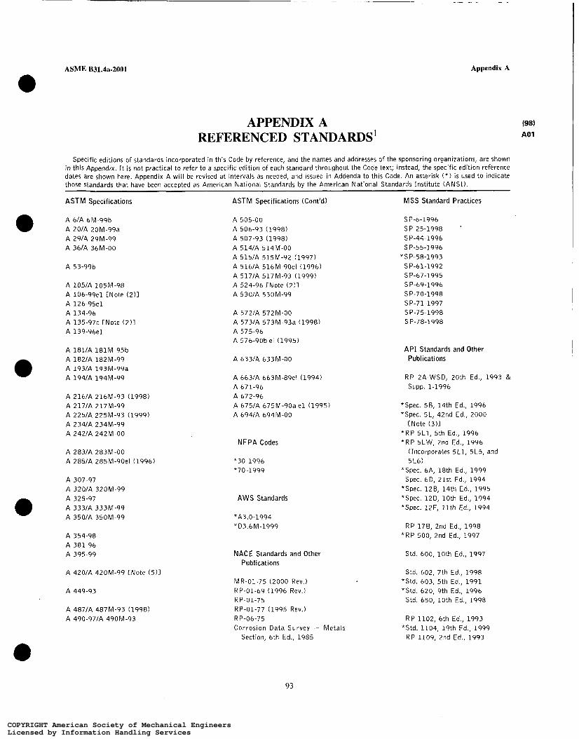
ASME B31.4a-2001 Appendix A
APPENDIX A REFERENCED STANDARDS'
Specific editions of standards incorporated in this Code by reference, and the names and addresses of the sponsoring organizations, are shown in this Appendix. It is not practical to refer to a specific edition of each standard throughout the Code text; instead, the specific edition reference dates are shown here. Appendix A will be revised at intervals as needed, and issued in Addenda to this Code. An asterisk ( * ) i s used to indicate those standards that have been accepted as American National Standards by the American National Standards Institute (ANSI).
ASTM Specifications
A 6IA 6M-99b 0 A 20lA 20M-99a A 29lA 29M-99 A 36lA 36M-00
A 53-99b
A 105lA 105M-98 A 106-99e1 [Note ( 2 ) l A 126-95e1
A 135-97c [Note ( 2 ) l A 139-96e1
A 134-96
A 181lA 181M-95b A 182lA 182M-99 A 193/A 193M-99a A 194lA 194M-99
A 216lA 216M-93 (1998) A 217lA 217M-99 A 225lA 225M-93 (1999) A 234lA 234M-99 A 242lA 242M-O0
A 283lA 283M-O0 A 285lA 285M-90el (1996)
A 307-97 A 320/A 320M-99 A 325-97 0 A 333/A 333M-99 A 350lA 35OM-99
A 354-98 A 381-96 A 395-99
A 42OlA 420M-99 [Note ( 5 ) l
A 449-93
A 487lA 487M-93 (1998) A 490-97lA 49OM-93
ASTM Specifications (Cont'd)
A 505-00 A 506-93 (1998) A 507-93 (1998) A 514/A 514M-00 A 515lA 515M-92 (1997) A 516lA 516M-90el (1996)
A 524-96 [Note (213 A 517lA 517M-93 (1999)
A 530lA 53OM-99
A 572lA 572M-O0 A 573lA 573M-93a (1998)
A 576-90b el (1995) A 575-96
A 633lA 633M-O0
A 663lA 663M-89el (1994) A 671-96 A 672-96 A 675lA 675M-90a e l (1995) A 694lA 694M-O0
NFPA Codes
*30-1996 *70-1999
AWS Standards
*A3.0-1994 *D3.6M-1999
NACE Standards and Other Publications
MR-01-75 (2000 Rev.) RP-01-69 (1996 Rev.)
RP-01-77 (1995 Rev.)
Corrosion Data Survey - Metals
R P-01-75
RP-06-75
Section, 6th Ed., 1985
MSS Standard Practices
S P-6-1996 SP-25-1998 S P-44-1996 SP-55-1996
*SP-58-1993 SP-61-1992 SP-67-1995 SP-69-1996 SP-70-1998 SP-71-1997 SP-75-1998 SP-78-1998
API Standards and Other Publications
RP 2A-WSD, 20th Ed., 1993 & SUPP. 1-1996
*Spec. 56, 14th Ed., 1996 *Spec. 5L, 42nd Ed., 2000
*RP 5L1, 5th Ed., 1996 *RP 5LW, 2nd Ed., 1996
[Note ( 3 ) l
(Incorporates 5L1, 5L5, and 516)
*Spec. 6A, 18th Ed., 1999 Spec. 6D, 21St Ed., 1994
*Spec. 126, 14th Ed., 1995 *Spec. 12D, 10th Ed., 1994 *Spec. 12F, 11th Ed., 1994
RP 176, 2nd Ed., 1998 *RP 500, 2nd Ed., 1997
Std. 600, 10th Ed., 1997
Std. 602, 7th Ed., 1998 *Std. 603, 5th Ed., 1991 *Std. 620, 9th Ed., 1996
Std. 650, 10th Ed., 1998
RP 1102, 6th Ed., 1993 *Std. 1104, 19th Ed., 1999
RP 1109, 2nd Ed., 1993
93
COPYRIGHT American Society of Mechanical EngineersLicensed by Information Handling ServicesCOPYRIGHT American Society of Mechanical EngineersLicensed by Information Handling Services

Appendix A ASME B31.4a-2001
REFERENCED STANDARDS1 (CONT'D) 198)
A01 ASME Codes and Standards ASME Codes and Standards A P I Standards and Other Publications (Cont'dì (Cont'd)
*ASME Boiler and Pressure Vessel RP 1110, 4th Ed., 1997 Code, 1 9 9 8 Ed. and 1 9 9 9 *B16.20-1998 & Addenda 2000 RP 1111, 3rd Ed., 1999 Addenda * B16.21-1992 RP 1117, 2nd Ed., 1996 *B16.25-1997
*B1.1-1998 *B16.28-1994 *B1.20.1-1983 (R1992) *B31G-1991 Publ. 2015, 5th Ed., 1994
Publ. 2200, 3rd Ed., 1994 *B1.20.3-1976 (R1998) *B31.5-1992 & Addenda-1994 Publ. 2201, 4th Ed., 1995 "B36.10M-1996
*616.5-1996 [Note (4)7 *B36.19M-1985 (R1994) API Manual of Petroleum *Bl6.9-1993
Measurement Standards * B16.10-1992
NOTES: (1) The issue date shown immediately followinq the number of the standard (e.g., A 53-96, 81.1-1998, and SP-6-1996 i s the effective date
of issue (edition) of the standard: ( 2 ) Approved only if mil l hydrostatic test i s performed. (3) Use of bell and spigot. line pipe not permitted. (4) Limited as set forth in para. 402.2.1. (5) A 420/A 420M Grade WPL9 is not suitable for anhydrous ammonia due t o copper content.
Titles of standards and specifications listed above which are referenced in the text but do not appear in Table 423.1 - Material Standards or Table 426.1 - Dimensional Standards are as follows:
A P I A P I API A P I API A P I API API API API API API API A P I API API A P I API API ASME
ASME
ASME AWS AWS NACE NACE NACE NACE NACE NACE
. . . ZA-WSD 5 L 1 5LW 128 12 D 1 2 F 178 500 620 650 1102 1104 1109 1110 1111 2015 2200 2201
B31G
831.5 A3.0 D3.6 . . . MR-01-75 RP-01-69 RP-01-75 R P-01-77 RP-06-75
Manual of Petroleum Measurement Standards Recommended Practice for Planning, Designing, and Constructing Fixed Platforms - Working Stress Design Recommended Practice for Railroad Transportation of Line Pipe Recommended Practice for Tansportation of Line Pipe on Barges and Marine Vessels Specification for Bolted Tanks for Storage of Production Liquids Specification for Field Welded Tanks for Storage of Production Liquids Specification for Shop Welded Tanks for Storage of Production Liquids Recommended Practice for Flexible Pipe Classification of Locations for Electrical Installations at Petroleum Facilities Design and Construction of Large, Welded, Low-Pressure Storage Tanks Welded Steel Tanks for O i l Storage Recommended Practice for Liquid Petroleum Pipelines Crossing Railroads and Highways Standard for Welding Pipelines and Related Facilities Recommended Practice for Marking Liquid Petroleum Pipeline Facilities Recommended Practice for Pressure Testing of Liquid Petroleum Pipelines Recommended Practice for Design, Construction, Operation and Maintenance of Offshore Hydrocarbon Pipelines Cleaning Petroleum Storage Tanks Repairing Crude Oil, Liquefied Petroleum Gas, and Product Pipelines Procedures for Welding or Hot Tapping on Equipment in Service Boiler and Pressure Vessel Code, Section VI11 Division 1 Pressure Vessels, Section VI11 Division 2 Alternative
Manual for Determining the Remaining Strength of Corroded Pipelines: A Supplement to 831, Code for Pressure
Refrigeration Piping Welding Terms and Definitions Specification for Underwater Welding Corrosion Data Survey - Metals Section Sulfide Stress Cracking Resistant Metallic Materials for O i l Field Equipment Recommended Practice - Control of External Corrosion on Underground or Submerged Metallic Piping Systems Recommended Practice: Control of Internal Corrosion in Steel Pipelines Systems Mitigation of Alternating Current and Lightning Effects on Metallic Structures and Corrosion Control Systems Recommended Practice: Control of Corrosion on Offshore Steel Pipelines
Rules for Pressure Vessels, and Section I X Welding and Brazing Qualifications
Piping
94
COPYRIGHT American Society of Mechanical EngineersLicensed by Information Handling ServicesCOPYRIGHT American Society of Mechanical EngineersLicensed by Information Handling Services

ASME B31.4a-2001
REFERENCED STANDARDSI (CONT’D)
NFPA 30 Flammable and Combustible Liquids Code NFPA 70 National Electrical Code
Specifications and standads of the following organizations appear-in Appendix A:
AN SI American National Standards Institute, Inc. 11 West 42nd Street New York, NY 10036 212 642-4900
API American Petroleum Institute Order Desk O 1220 L Street, N.W. Washington, DC 20005-4070 202 682-8375
ASME The American Society of Mechanical Engineers Three Park Avenue New York, NY 10016-5990 212 591-8500
ASME Order Department 22 Law Drive Box 2900 Fairfield, NJ 07007-2900 800 843-2763 201 882-1167
Appendix A
(98) A01
AWS American Welding Society P.O. Box 351040 550 N.W. LeJeune Road Miami, FL 33126 305 443-9353
MSS Manufacturers Standardization Society of the
127 Park Street, N.E. Vienna, VA 22180
Valve and Fittings Industry, Inc.
703 281-6613
NACE National Association of Corrosion Engineers 1440 South Creek Drive P.O. Box 218340 Houston, TX 77218-8340 713 492-0535
NFPA National Fire Protection Association 1 Batterymarch Park Quincy, M A 02269-9101 617 770-3000
ASTM American Society for Testing and Materials 100 Bar Harbor Drive West Conshohocken, PA 19428-2959 610 832-9500
95
COPYRIGHT American Society of Mechanical EngineersLicensed by Information Handling ServicesCOPYRIGHT American Society of Mechanical EngineersLicensed by Information Handling Services

STD-ASME B 3 L - Y - E N G L 1‘198 0757b70 0h0729q 205 I
ASME B31.4-199% Edition B-1-B-3
APPENDIX B SUBMITTAL OF TECHNICAL INQUIRIES TO THE B31 PRESSURE
PIPING COMMITTEE
B-1 INTRODUCTION
The ASME €331 Pressure Piping Committee and its Section Committees meet regularly to consider revisions of the Code rules, new Code rules as dictated by technological development, Code Cases, and Code inter- pretations. This Appendix provides guidance to Code users for submitting technical inquiries to the Commit- tee. Technical inquiries include requests for revisions or additions to the Code rules, requests for Code Cases, and requests for Code interpretations.
Code Cases may be issued by the Committee when the need is urgent. Code Cases clarify the intent of existing Code requirements or provide alternative re- quirements. Code Cases are written as a question and a reply and are usually intended to be incorporated into the Code at a later date. Code interpretations provide the meaning of or the intent of existing rules in the Code and are also presented as a question and a reply. Both Code Cases and Code interpretations are published by the Committee.
The Code rules, Code Cases, and Code interpretations established by the Committee are not to be considered as approving, recommending, certifying, or endorsing any proprietary or specific design or as limiting in any way the freedom of manufacturers or constructors to choose any method of design or any form of construction that conforms to the Code rules.
As an alternative to the requirements of this Appen- dix, members of the Committee and its Section Commit- tees may introduce requests for Code revisions or additions, Code Cases, and Code interpretations at their respective Committee meetings or may submit such requests to the secretary of a Section Committee.
Inquiries that do not comply with the provisions of this Appendix or that do not provide sufficient informa- tion for the Committee’s full understanding may result in the request being returned to the inquirer with no action.
B-2 INQUIRY FORMAT
Submittals to the Committee shall include:
(a) Purpose. Specify one of the following: (I) revision of present Code rule(s); (2) new or additional Code rule(s); (3) Code Case; (4) Code interpretation.
(b) Background. Provide the information needed for the Committee’s understanding of the inquiry, being sure to include reference to the applicable Code Section, Edition, Addenda, paragraphs, figures, and tables. Pref- erably, provide a copy of the specific referenced portions of the Code.
The inquirer may desire or be asked to attend a meeting of the Committee to make a formal presentation or to answer questions from the Committee members with regard to the inquiry. Attendance at a Committee meeting shall be at the expense of the inquirer. The inquirer’s attendance or lack of attendance at a meeting shall not be a basis for acceptance or rejection of the inquiry by the Committee.
( c ) Presentations.
B-3 CODE REVISIONS OR ADDITIONS
Requests for Code revisions or additions shall provide the following:
(a ) Proposed Revision(s) or Aa¿iitions(s). For revi- sions, identify the rules of the Cade that require revision and submit a copy of the appropriate rules as they appear in the Code marked up with the proposed revision. For additions, provide the recommended word- ing referenced to the existing Code rules.
(6) Statement of Need. Provide a brief explanation of the need for the revision(s) or addition(s).
(c ) Background information. Provide background information to support the revision(s) or addition(s) including any data or changes in technology that form the basis for the request that will allow the Committee to adequately evaluate the proposed revision(s) or addi- tion(s). Sketches, tables, figures, and graphs should be submitted as appropriate. When applicable, identify any pertinent paragraph in the Code that would be affected by the revision(s) or addition(s) and paragraphs in the Code that reference the paragraphs that are to be revised or added.
97
COPYRIGHT American Society of Mechanical EngineersLicensed by Information Handling ServicesCOPYRIGHT American Society of Mechanical EngineersLicensed by Information Handling Services

B-3-B-6
B-4 CODE CASES
Requests for Code Cases shall provide a statement of need and background information similar to that defined in B-3(b) and B-3(c), respectively, for Code revisions or additions. The proposed Code Case should identify the Code Section and be written as a question and a reply in the same format as existing Code Cases.
B-5 CODE INTERPRETATIONS
Requests for Code interpretations
(a) Inquiry. Provide a condensed following:
shall provide the
and precise ques- tion, omitting superfluous background information, and, when possible, composed in such a way that a “yes” or a “no” reply, possibly with brief provisos, is accept- able. The question should be technically and editorially correct.
(b) Reply. Provide a proposed reply that will clearly and concisely answer the inquiry question. Preferably, the reply should be “yes” or “no” possibly with brief provisos.
ASME B31.4-1998 Edition
(c ) Background Information. Provide any back- ground information that will assist the Committee in understanding the proposed inquiry and reply.
B-6 SUBMITTAL AND RESPONSE (981
Submittals to and responses from the Committee shall meet the following:
(a) Submittal. Inquiries from Code users shall prefer- ably be submitted in typewritten form; however, legible handwritten inquiries will also be considered. They shall include the name, address, telephone number, and fax number, if available, of the inquirer and be mailed to the following address:
Secretary ASME B31 Committee Three Park Avenue New York, NY 10016-5990 (b) Response. The Secretary of the appropriate
Section Committee shall acknowledge receipt of each properly prepared inquiry and shall provide a written response to the inquirer upon completion of the re- quested action by the appropriate Section Committee.
98
COPYRIGHT American Society of Mechanical EngineersLicensed by Information Handling ServicesCOPYRIGHT American Society of Mechanical EngineersLicensed by Information Handling Services

ASME B31.4-1998 Edition
Abandoning a piping system, 457 Accidental ignition, prevention of, 452.7 Additive circumferential stresses, 402.3.2(e),
Additive longitudinal stresses, 402.3.2(d) Allowable stresses and other stress limits, 402.3 Allowances and tolerances, wall thickness, 402.4 Ambient influences, 401.4 Ammonia, liquid anhydrous, 400.2, 423.2.5, 450.l(d),
Anchoring, 419.l(c), (d), 421.l(c) Arc bums, 434.8.7(a), 436.5.1(a)(2), 451.6.2(a)(3),
Assembly of piping components, 435 Attachments to piping, 404.3.4 Auxiliary piping, 422
434.13.4(c), 45 1.9(b)
454(e)(7), 462.1 .(d)
(b)(4), (b)(5)
Backfilling, 434.1 1 Bending, properties, unidentified pipe, 437.6.2 Bends, pipe
design, 404.2.1 fabrication, 434.7.1 flattening, 434.7.l(b) mitered bends, 406.2.2, 434.7.2 radius, 406.2.1(b) wrinkle bends, 406.2.4
Bolting, 408.5, 425.4 procedure, 435.2 specifications, Tables 423.1 and 426.1
Branch connections, 404.3.1 Building installation, 434.20.3 Butt welds, 41 1.2, 434.8.6(a)
type groove and joint design, 434.8.6(a)
Carbon dioxide, 400.2, 402.5, 437.4.1, 460 Casings under railroads and highways, 434.13.4(b),
Cast iron, 423.2.4 flanges, 408.1.1(c) valves, 407.l(b)
45 1.9(a), 461.1.2(f)
Cathodic protection system, 461.1.3 Changes affecting safety, 450.2(d)
Index
Circumferential stresses, additive, 402.3.2(e),
Clearance, pipelines and underground structures,
Closures
Coating, protective, application and inspection,
434.13.4(c), 45 1.9(b)
434.6(c)
selection and limitations, 406.6
436.5.1(b), 451.6.2(~)(10), 461.1.2, 462.1(c), 463.1, 464(a)(3)
402.3.1(a), 402.3.1(d), 405.2.1(d), 434.7.1(a) Cold worked steel pipe, special requirements, Table
Combined stress calculations, 419.6.4 Combustible materiais, storage of, 452.4 Communications, 45 1.2 Connections to main lines, 434.16 Construction specifications, 434.1 Contraction, thermal, 401.7 Control piping, 422.3 Corrective measures for corrosion control, 464 Corrosion allowance, 402.4.1 Corrosion control
pipelines cathodic protection system, 461.1.3 corrective measures, 464 electrical interference, 46 1.1.6 electrical isolation, 461.1.4 electrical test leads, 461.1.5 external corrosion, 434.19, 453, 460, 461, 463 internal corrosion, 434.19, 453, 460, 462 monitoring, 461.3, 462.3, 463.3
protective coatings, application and inspection, 436.5.1(b), 451.6.2(~)(10), 461.1.2, 462.l(c), 463.1, 464(a)(3)
pump stations, tank farms, and terminals, 461.1 . I (b), 461.2(b)
Corrosion limits, 45 1.6.2(a)(6), (a)(7) Corrosion records, 455,465 Coupled joints, 418.1 Couplings, 406.3 Cover, minimum for buried pipelines, Table 434.6(a) Crosses
design, 404.3.1(a) selection and limitations, 406.5
bridge attachments, 434.13.3 Crossings, 434.13
99
COPYRIGHT American Society of Mechanical EngineersLicensed by Information Handling ServicesCOPYRIGHT American Society of Mechanical EngineersLicensed by Information Handling Services

STD-ASME B3L-4-ENGL 1798 II 0757b70 Ob09297 TL4 M
Index
highway crossings, 434.13.4, 45 1.9 overhead structures, 434.13.2 railroad crossings, 434.13.4, 45 1.9 river and stream crossings, 434.13.1 safety precautions, 434.3.2(c) underground structures, 434.6(c) underwater construction, 434.13.1(a)
Currents, dynamic effects, 401.5.6 Curved segments of pipe, 404.2 Cutting and welding, safe practices in, 434.8.l(c),
451.6.1, 451.6.2(~)(1), 452.7(c)
Dead loads, 401.6.2 Definitions, 400.2 Derating, operating pressure, 45 1.7 Design
auxiliary and other specific piping, 422 conditions, 401 criteria, 402,403 expansion and flexibility, 419 external pressure, 401.2.3, 404.1.3 factor, 402.3.1 internal pressure, 401.2.2, 404.1.2 loads on pipe supporting elements, 420 pipe supporting elements, 421 pressure design of piping components, 404
curved segments of pipe, 404.2 flanges, 404.5 intersections, 404.3 reducers, 404.6 straight pipe, 404.1 other pressure containing components, 404.7
selection and limitations of piping components fittings, elbows, bends, and intersections, 406 flanges, facings, gaskets, and bolting, 408 pipe, 405 valves, 407
flanged, 4 12 sleeve, coupled, and other patented joints, 418 threaded, 4 14 welded, 41 1
temperature, 401.3.1
selection and limitation of piping joints
Dikes or firewalls, 434.21.5 Dimensional requirements, 426 Disposal piping, 422.6 Ditching, 434.6 Dynamic effects, 401.5
ASME 831.4199% Edition
Elbows design, 404.2.2 installation, 434.7.3 selection and limitations, 406.2.3
Electrical installations, 434.22, 461.1.3(c) Electrical interference, corrosion control, 461.1.6 Electrical isolation, corrosion control, 461.1.4 Electrical test leads for corrosion control, 461.1.5 Emergency plan, 450.2(c), 454 Expansion, allowable stresses, 402.3.2(c) Expansion, fluid effects, 401.4.2 Expansion, thermal, 401.7 Expansion and flexibility, 419 Expansion coefficient, 419.6.1 External corrosion, 434.19, 453, 460, 461, 463 External design pressure, 401.2.3, 404.1.3 Extruded outlet headers, 404.3.1(b)
Fabrication (construction), 434 Fencing, 434.20.2, 434.2 1.2, 452.5 Ferrous pipe, 405.2.1 Fillet welds, 434.8.6(b) Fire protection, 434.20.7 Firewalls, dikes or, 434.21.5 Fish tails and flat closures, 406.6.3 Fittings
design, 404.2.2, 404.3.1(a), 404.5, 404.6, 404.7 dimensions, 426 flexibility and stress intensification factors,
installation, 434.7 materials, 423 selection and limitations, 406, 408
419.6.4(c)
Flanged joints, selection and limitation, 412 Flanges
attachment, welding details for, 434.8.6(b) bolting, 408.5, 425.4 bolting specifications, Tables 423.1 and 426.1 cast iron, 408.1.1(c) facings, 408.3 pressure design, 404.5 selection and limitations, 408 specifications, Tables 423.1 and 426.1
Flattening, pipe bends, 434.7.1 (b) Flattening test for pipe, 437.6.2(a) Flexibility, expansion and, 419 Flexibility factors, 419.6.4(c) Fluid expansion effect, 401.4.2
Earthquake, dynamic effect, 401 S.3 Gaskets, selection and limitation, 408.4
100
COPYRIGHT American Society of Mechanical EngineersLicensed by Information Handling ServicesCOPYRIGHT American Society of Mechanical EngineersLicensed by Information Handling Services
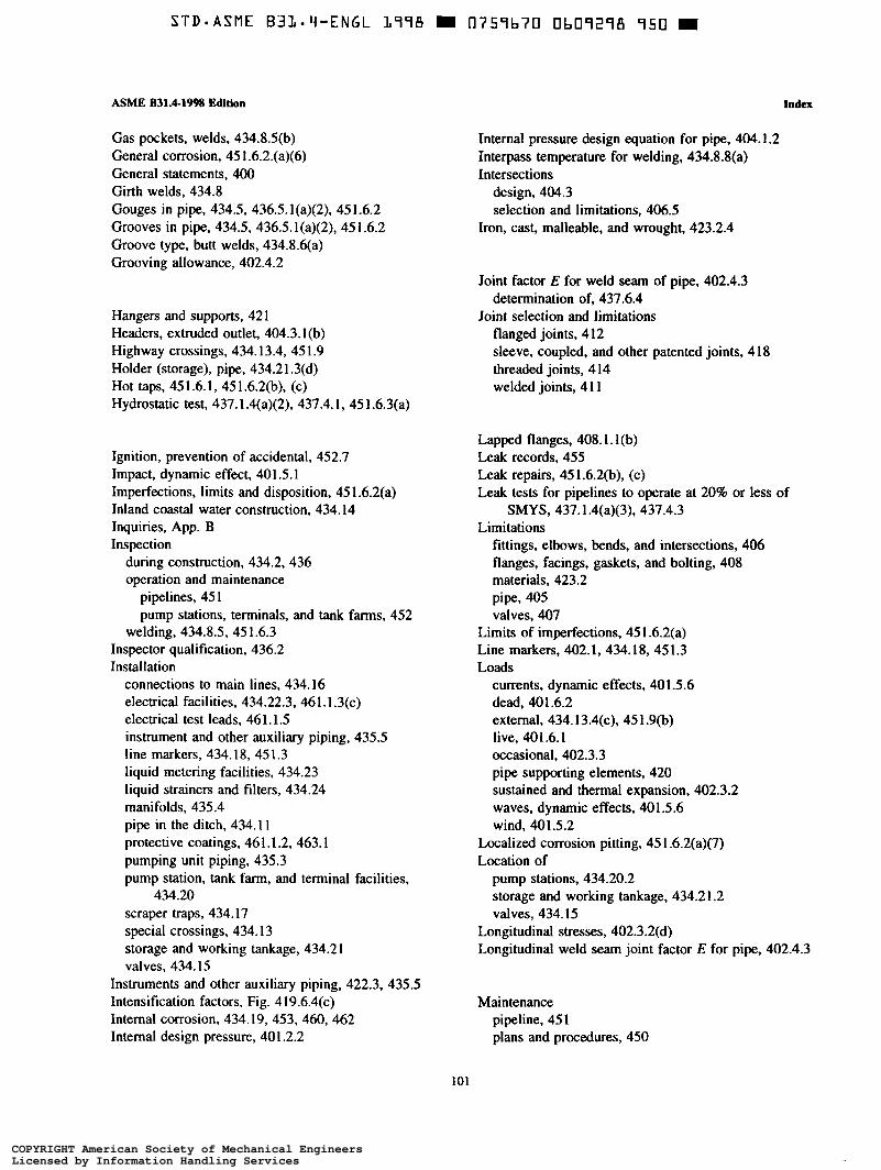
S T D - A S M E B3L.Y-ENGL 1976 0759b70 Ob09278 750
ASME B31.4-199% Edition
Gas pockets, welds, 434.8.5(b) General corrosion, 45 1.6.2.(a)(6) General statements, 400 Girth welds, 434.8 Gouges in pipe, 434.5, 436.5.1(a)(2), 451.6.2 Grooves in pipe, 434.5, 436.5.l(a)(2), 45 1.6.2 Groove type, butt welds, 434.8.6(a) Grooving allowance, 402.4.2
Hangers and supports, 421 Headers, extruded outlet, 404.3.1 (b) Highway crossings, 434.13.4, 451.9 Holder (storage), pipe, 434.21.3(d) Hot taps, 451.6.1, 45 1.6.2(b), (c) Hydrostatic test, 437.1.4(a)(2), 437.4.1, 45 1.6.3(a)
Ignition, prevention of accidental, 452.7 Impact, dynamic effect, 401.5.1 Imperfections, limits and disposition, 451.6.2(a) Inland coastal water construction, 434.14 Inquiries, App. B Inspection
during construction, 434.2, 436 operation and maintenance
pipelines, 45 1 pump stations, terminals, and tank farms, 452
welding, 434.8.5, 45 1.6.3 Inspector qualification, 436.2 Installation
connections to main lines, 434.16 electrical facilities, 434.22.3, 461.1.3(c) electrical test leads, 461.1.5 instrument and other auxiliary piping, 435.5 line markers, 434.18, 45 1.3 liquid metering facilities, 434.23 liquid strainers and filters, 434.24 manifolds, 435.4 pipe in the ditch, 434.1 1 protective coatings, 461.1.2, 463.1 pumping unit piping, 435.3 pump station, tank farm, and terminal facilities,
scraper traps, 434.17 special crossings, 434.13 storage and working tankage, 434.21 valves, 434.15
434.20
Instruments and other auxiliary piping, 422.3, 435.5 Intensification factors, Fig. 4 19.6.4(c) Internal corrosion, 434.19, 453, 460, 462 Internal design pressure, 401.2.2
Index
Internal pressure design equation for pipe, 404.1.2 Interpass temperature for welding, 434.8.8(a) Intersections
design, 404.3 selection and limitations, 406.5
Iron, cast, malleable, and wrought, 423.2.4
Joint factor E for weld seam of pipe, 402.4.3 determination of, 437.6.4
Joint selection and limitations flanged joints, 412 sleeve, coupled, and other patented joints, 418 threaded joints, 414 welded joints, 4 11
Lapped flanges, 408.1.1 (b) Leak records, 455 Leak repairs, 451.6.2(b), (c) Leak tests for pipelines to operate at 20% or less of
Limitations SMYS, 437.1.4(a)(3), 437.4.3
fittings, elbows, bends, and intersections, 406 flanges, facings, gaskets, and bolting, 408 materials, 423.2 pipe, 405 valves, 407
Limits of imperfections, 45 1.6.2(a) Line markers, 402.1, 434.18, 451.3 Loads
currents, dynamic effects, 401.5.6 dead, 401.6.2 external, 434.13.4(c), 45 1.9(b) live, 401.6.1 occasional, 402.3.3 pipe supporting elements, 420 sustained and thermal expansion, 402.3.2 waves, dynamic effects, 401.5.6 wind, 401 5 2
Localized corrosion pitting, 45 1.6.2(a)(7) Location of
pump stations, 434.20.2 storage and working tankage, 434.2 1.2 valves, 434.15
Longitudinal stresses, 402.3.2(d) Longitudinal weld seam joint factor E for pipe, 402.4.3
Maintenance pipeline, 451 plans and procedures, 450
101
COPYRIGHT American Society of Mechanical EngineersLicensed by Information Handling ServicesCOPYRIGHT American Society of Mechanical EngineersLicensed by Information Handling Services

STD-ASME U3L-'i-ENGL 177A U 0757L70 Ob07277 877 W
Index
pump stations, terminals, and tank farms, 452 relief valves, pressure limiting devices, etc., 452.3 valves, 45 1.7
Malleable iron, 423.2.4 Markers, line, 402.1, 434.18, 451.3 Materials, 423
limitations, 423.2 qualification of, 423.1 (b) specifications, 423.1
Maximum steady state operating pressure, 401.2.2,
Meters, 434.23 Mitered bends
451.1, 451.7, 456(b)
fabrication, 434.7.2 limitations, 406.2.2
Modulus of elasticity, 419.6.2 Monitoring, corrosion control, 461.3, 462.3, 463.3 Monitoring, flow, 452.l(b) Multiple openings, reinforcement, 404.3.1 (e)
Nominal wall thickness, 404.1.1 Normal operating conditions, 402.2.3 Normal operation, variations from, 402.2.4
Offshore allowable stresses and other stress limits, A402.3 allowances, A402.4 backfilling, A434.11 bends, pipe
bends, miters and elbows, A406.2, A434.7 made from pipe, A434.7.1
bottom soils, A401.9.4 branch connections, A404.3.1 cathodic protection system, A461.1.3 closures, A406.6
construction, A434
corrosion control
fabricated, A406.6.4
inspection, A434.2
external corrosion control, A461, A463 new installations, A46 1.1, A463.1 offshore piping systems exposed to atmospheric
offshore submerged pipelines, A46 1 conditions, A463
general, A460, A461.1.1 internal corrosion control, A462
definitions, A400.2 derating a pipeline to a lower operating pressure,
A45 1.7
ASME B31.4-1998 Edition
design and protection of special assemblies,
design A402.3.10
conditions, A401 general, A401.1 criteria, A402 expansion and flexibility, A402.3.6 clamps and supports, A402.3.7 connectors and flanges, A402.3.8 factors for offshore pipeline systems, Table
402.3.5(a) flexible pipe, A402.3.11 load classifications
hydrostatic test, A401.11.1 installation, A401.9.1 operational, A401.10.1
other design considerations, A4 10 pressure components, A404
pipe supporting elements, A421 pipeline crossings, A402.3.12 structural riser protectors, A402.3.9
disposition of defects, A45 1.6.2 ditching, A434.6 electrical interference, A461.1.6 electrical isolation, A461.1.4 emergency plan, A454 environmental loads
during hydrostatic test, A401.11.3 during installation, A401.9.3 during operation, A401.10.3
expansion and flexibility, A419 fencing, A452.5 fittings, elbows, bends, and intersections, A406 flanges, facings, gaskets and bolting, A408
flanges, A408.1 facings, A408.3 general, A408.1.1, A408.3.1
flexible pipe, A405.3 repair, A45 1.6.4
general statements, A400 handling, hauling, stringing, and storing, A434.4 hydrostatic test design considerations, A401.11 hydrostatic test loads, A40 1.1 1.2 inspection, A436, A45 1.1 1
offshore pipeline risers, A451.10 type and extent of examination, A436.5 visual, A436.5. I
installation, design considerations, A401.9 loads, A40 1.9.2 procedures and equipment selection, A434.14.2
intersections, A404.3 leak testing, A437.4.3
I02
COPYRIGHT American Society of Mechanical EngineersLicensed by Information Handling ServicesCOPYRIGHT American Society of Mechanical EngineersLicensed by Information Handling Services

ASME B31.4-1998 Edition
limitations on materials, A423.2 line markers, A434.18 markers, A45 1.3 materials, A423
mitered elbows, A406.2.2 monitoring, A461.3, A462.3 movement of existing pipelines, A434.14.3 offshore
acceptable materials and specifications, A423. I
design conditions, A401.1.1 pipeline construction, A434.14 platform, pump station, terminal and tank farm
operation and maintenance, A452 operational, design considerations, A401.10
orange peel swages, A406.4.2 patrolling, A45 1.5 pigs and internal inspection tools, A410.1 pipe, A405
loads, A40 1.10.2
ferrous pipe, A405.2.1 general, A404.1.1 metallic pipe, A405.2 straight pipe, A404.1
pipe depth and alignment, A434.14.1 pipeline operation and maintenance, A45 1
plans and procedures, A450.2 procedures affecting the safety of liquid
transportation piping systems, A450 pipeline repairs, A45 1.6
general, A45 1.6.1 prevention of accidental ignition, A452.7 protective coating, A461.1.2 qualification
of inspectors, A436.2 tests, A437.6
railroads and highways crossing existing pipelines, A45 1.9
records, A437.7 reductions, A406.4 repair of flexible pipe, A45 1.6.4 right of way, A434.3 right of way maintenance, A45 1.4 route selection considerations, A40 1.12 scope, A400.1 special components, A410.2 special crossings, A434.13 strength criteria
during installation and testing, A402.3.4 during operations, A402.3.5
stress relieving, A434.8.9 survey and staking or marking, A434.3.3 test leads. A46 1.1.5
index
testing, A437 general, A437.1 pressure, A437.4 testing after new construction, A437.1.4
threaded joints, A414 general, A414.1
used piping components and equipment, A409 valves, A407
block and isolating valves, A434.15 general, A407.1, A434.15.1 maintenance, A45 1.8
water crossing, A434.13.1 welding, A434.8
weld joint factors, A402.4.3 welding qualifications, A434.8.3 welding quality, A434.8.5
Operating pressure, 401.2.2, 451.1, 451.7, 456 Operation and maintenance
pipeline, 45 1 plans and procedures, 450.2 procedures affecting safety, 450 pump station, terminal, and tank farm, 452 qualifying for a higher operating pressure, 456 records, 455
Orange peel bull plugs, 406.6.3 Orange peel swages, 406.42 Organizations, standards and specifications of, App. A Overpressunng, protection against, 402.2.4
Patrolling, 45 1.5 Pipe, steel
bends, 404.2.1 buckles, 434.5, 436.5.1(a)(2) coated or lined, 405.2. i(e) cold worked steel, special limitations, Table
dents, 434.5, 436.5.1(a)(2), 451.6.2 design, 404.1 end of preparations, standard, 434.8.6(a) expansion and flexibility, 419 flattening, test for, 437.6.2(a) gouges and grooves, 434.5, 436.5.l(a)(2), 45 1.6.2 handling, hauling, stringing, and storing, 434.4 hangers, 42 1.1 (e) holder for storage, 434.2 1.3(d) inspection, 436 installation of, in the ditch, 434.10 installation of, special crossings, 434.13 joint factor E for weld seam, 402.4.3 limitations of design values, 402.3.1(g) protection from unusual external conditions, 402. I
402.3.1(a), 402.3.1(d), 434.7.1(a), 405.2.l(d)
i 03
COPYRIGHT American Society of Mechanical EngineersLicensed by Information Handling ServicesCOPYRIGHT American Society of Mechanical EngineersLicensed by Information Handling Services

STD*ASME B 3 L * + F : N G L L79h U D759h70 Ob07301 275
ASME B31.4-1998 Edition Index
protective coatings, 436.5.1(b), 45 1.6.2(c)( lo), 461.1.2, 462.1(c), 463.1, 464(a)(3)
qualification of specification ASTM A 120, 405.2.1(c)
reuse of, 405.2.1(b), (c) selection and limitations, 405 specifications, list of, Tables 423.1 and 426.1 specified minimum yield strength, Table 402.3. i(a) supporting elements, loads and design, 420,421 surface requirements, 434.5 testing, 437, 45 1.6.3, 456(b) threads, 414.1, 426.3 unidentified or used, limitations, 405.2.1(b), (c) unidentified, S value, 402.3.1(c) used, S value, 402.3.1(b) welding, 434.8
Pipeline repairs, 45 i .6 Pipelines on bridges, 434. i 3.3 Pipe-type holders (storage), 434.2 1.3(d) Piping
abandoning of, 457 anchorage for
buried, 419. I(b), (c), 419.7.3(e) exposed, 419.l(d), 419.7.3(e), 421.1
control, instrument, and other auxiliary, 422;3, 435.5 hangers, 42 l.l(e) pressure disposal, 422.6 supports for, 420, 421 testing, 437, 45 1.6.3 welding, 434.8
Pitting, localized corrosion, evaluation of, 45 1.6.2(a)(7) Plan, emergency, 450.2(c), 454 Plans and procedures, operation and maintenance, 450 Platform risers, 45 I. 1 O Plugs, orange peel bull, 406.6.4 Pneumatic, testing, 437.4.3 Poisson’s ratio, 419.6.3 Preheating, and interpass temperature for welding,
Pressure 434.8.8
derating, 45 1.7 design, 401.2, 404 disposal piping, 422.6 limiting devices
capacity of, 402.2.4 installation, 434.20.6 testing, 437.1.4(c), 452.2
maximum steady state operating, 401.2.2, 45 1.1, 456 qualifying for higher operating, 456 ratings, 402.2 testing, 437, 45 1.6.3, 456(b)
Prevention of accidental ignition, 452.7
Procedures, operation and maintenance, 450 Procedures, pipe bending, 434.7.1 Procedures and welders, qualification of, 434.8.3 Proof tests, 404.7 Proprietary items, 400.1.2(g)
Protection of pipelines against unusual external
Protective coatings, 436.5.1(b), 451.6.2(c)( IO), 461.1.2,
Pump stations, tank farms, and terminals, 434.20
limitations, 423.2.4(b)
conditions, 402.1
462.1(c), 463.1, 464(a)(3)
building installation, 434.20.3 corrosion control, 46 1.1.1 (b), 46 i .2(b) electrical facilities, 434.22 fenced areas, 434.20.2, 452.5 fire protection, 434.20.7 location, 434.20.2 operation and maintenance, 452 piping, 434.20.5 pressure disposal piping, 422.6 pumping equipment and prime movers, 434.20.4 safety devices, 434.20.6 testing, 437, 456(b)
Qualification inspectors, 436.2 materials, 423 procedures and welders, 434.8.3 records, welding, 434.8.3(d)
Qualifying system for higher pressure, 456
Radiograph examination crossings, 434.8.5 field welds, 434.8.5, 451.6.3 procedures, 434.8.5(a)(2) tie-ins, 434.8.5, 437.1.4(b), 451.6.3
Radius, pipe bends, 406.2.1(b) Railroad crossings, 434.13.4, 45 1.9 Railroad transportation of pipe, 434.4 Ratings, pressure, 402.2 Records
corrosion of pipelines, 455, 465 design, construction, and testing, 437.7 inspections, 455(e), 465(b) pipeline leaks, 455(d) pipeline patrol, 455(b) qualifying system for higher pressure, 456(d) welders qualification tests, 434.8.3(d) welding procedures, 434.8.3(d)
104
COPYRIGHT American Society of Mechanical EngineersLicensed by Information Handling ServicesCOPYRIGHT American Society of Mechanical EngineersLicensed by Information Handling Services

ASME B31.4-1998 Edition
Reducers design, 404.6 selection and limitations, 406.4
Reference standards, App. A Reinforcement
extruded outlets, 404.3. I(b) welded branch connections, 404.3.1(c). (d), (e)
inspection and testing of, 437.1.4(c), 452.2 installation, 434.20.6
Removal or repair of defects or imperfections arc bums, 434.8.7(a), 45 1.6.2 welds, 434.8.7(b), 45 1.6.2 other, 434.5, 434.8.7(c), 451.6.2
Relief valves
Repairs, pipeline, 45 1.6 Repairs, testing, 45 1.6.3 Responsibility for qualification of procedures and
welders, 434.8.3(e) Reuse of steel pipe, 405.2.l(b), (c) Right of way, 434.3, 451.4 Risers, platform, 45 1.10 Road and highway crossings, 434.13.4, 451.9
Safety devices installation, 434.20.6 maintenance, 452.2 testing, 437.1.4(c), 452.2
scope, 400.1 Scraper traps, 434.17 Signs, 452.6 Slag inclusions, welds, 434.8.5(b) Smoking, 452.7 Spacing of valves, 434.15.2 Specification ASTM A 120 pipe, qualification,
Specifications 405.2.1(c)
electrical installations, 434.22, 46 1.1.3(e) list of, App. A material, 423.1 pipeline construction, 434.1 pump station construction, 434.20 storage and working tankage, 434.21
Specified minimum yield strength, Table 402.3.1(a) Spiral weld seam joint factor E for pipe, 402.4.3 Standards, dimensional, 426.1 Standards and specifications, Tables 423.1 and 426. I ,
Standards of acceptability of welds, 434.8.5(b) Storage and working tankage, 434.21, 452.3 Storage of combustible materials, 452.4
APP A
Index
Stress analysis (flexibility), 419.7 calculations, combined, 419.6.4 intensification factors, Fig. 419.6.4(c) limits, 402.3
occasional loads, 402.3.3 sustained loads and thermal expansion, 402.3.2
relieving, 434.8.9, 435.4.3, 435.4.4 Stresses, allowable, 402.3 Subsidence, dynamic effect, 401.5.5 Supports, braces and anchors, 42 1,l Surface defects, 434.5, 436.5.1 Surveying and staking or marking, 434.3.3 Swages, orange peel, 406.4.2
Tankage, 434.21, 452.3 Tank farms, pump stations, and terminals, 434.20, 452 Taps, hot, 451.6.1, 451.6.2(b), (c) Tees
design, 404.3.1(a) selection and limitations, 406.5
Temperature, 401.3 Terminals, pump stations, tank farms, 434.20, 452 Testing, 437
after construction, 437.1.4 fabricated items, 437.1.3 leak, 437.4.3 pressure limiting devices, 437.1.4(c), 452.2 qualifying for higher operating pressure, 456(b)(2) records, 437.7, 456(d) repairs, 45 1.6.3 systems or parts of systems, 437.1.4(a) tie-ins, 434.8.5, 437.1.4(b), 451.6.3 unidentified or used steel pipe, 437.6 welding, 434.8.5
Test leads, corrosion control, 461.1.5 Test pressure, 437.4 Test requirements, 437, 45 1.6.3, 456(b) Tests
corrosion control, 461.3, 462.3, 463.3 leak, for pipelines to operate at 20% or less of
SMYS, 437.1.4(a)(3), 437.4.3 qualification, unidentified or used steel pipe, 437.6 welding, 434.8.5, 45 1.6.3(b)
Thermal expansion, 4 19 coefficient of, 419.6.1
Thickness, steel pipe design, 404.1 determination, unidentified or used, 437.6.3
1 o5
COPYRIGHT American Society of Mechanical EngineersLicensed by Information Handling ServicesCOPYRIGHT American Society of Mechanical EngineersLicensed by Information Handling Services

Index
Tie-ins, 434.8.5, 434.9, 437.1.4(b), 451.6.3 Tolerances, wall thickness and defect, 402.4.5 Transition nipples, 434.7.3(b), 434.8.6(a)
Undercutting welds, 434.8.5(b) Unidentified or used steel pipe
limitations, 405.2.1(b), (c) qualification tests, 437.6
bending properties, 437.6.2 minimum yield strength value, 437.6.7 visual examination, 437.6.1 wall thickness, 437.6.3 weldability, 437.6.5 weld seam joint factor E, 437.6.4 yield strength determination, 437.6.6
Valves dimensional requirements, 426 installation and location, 434.15 maintenance
pipeline, 45 1.8 relief valves, etc., 452.2
materials, 423 selection and limitations, 407 spacing, 434.15.2 specifications and standards, Tables 423.1 and 426.1 testing relief valves, etc., 437.1.4(c), 452.2
Vibration, dynamic effect, 401 S.4
Wall thickness, steel pipe allowances and tolerances, 402.4 least nominal, 404.1 unidentified or used steel pipe, 437.6.3
Waves, dynamic effects, 401.5.6 Weight effects, 401.6 Weldability, unidentified or used steel pipe, 437.6.5 Welded branch connections, 404.3.1(c), (d), (e) Welders
qualification of, 434.8.3 requalification requirements, 434.8.3(c)
arc burns, 434.8.7(a), 436.5.l(a)(2), 45 1.6.2(a)(3), Welding, 434.8
(b)(4),
ASME B31.4-199% Edition
details for openings with encirclement, Fig. 404.3. i(c)(l) with localized reinforcement, Fig. 404.3.1 (c)(2) without reinforcement, Fig. 404.3.1(~)(3)
equal thickness, Fig. 434.8.6(a)-( 1) unequal thickness, Fig. 434.8.6(a)-(2)
end treatment, acceptable
filler metal, 434.8.2 general, 434.8.1 inspection and tests, 434.8.5(a), 436.5.l(b)(4), (b)(5),
maintenance, 45 1.6 preheating and interpass temperature for, 434.8.8 procedure, 434,8.3 processes, 434.8.2 qualification of procedures and welders, 434.8.3,
qualification records, 434.8.3(d) responsibility for qualification, 434.8.3(e) safe practices in cutting and welding, 434.8.1(c),
451.6.1, 451.6.2(~)(1), 452.7(c) standards of acceptability, 434.8.5(b) stress relieving, 434.8.9 terms, 434.8.1(b) tests, 434.8.5(a), 436.5.2(a), (b), 451.6.3 variables, 434.8.3(b)
bum-through areas, 434.8.5(b) cracks in, 434.8.5(b) discontinuities in, 434.8.5(b) fillet, 434.8.6(b) gas pockets, 434.8.5(b) inadequate penetration and incomplete fusion,
434.8.5(b) porosity, 434.8.5(b) removal or repair of defects, 434.8.7(b) slag inclusions, 434.8.5(b) tack, 434.8.6(c) types of, 434.8.6 undercutting, 434.8.5(b)
Wind, dynamic effect, 401.5.2 Wrinkle bends, 406.2.4
436.5.2(a), (b), 451.6.3
451.6.2(c)( i), (c)(2)
Welds
Yield strength specified minimum, steel pipe, Table 402.3. i(a) unidentified or used steel pipe, 437.6.6, 437.6.7
106
COPYRIGHT American Society of Mechanical EngineersLicensed by Information Handling ServicesCOPYRIGHT American Society of Mechanical EngineersLicensed by Information Handling Services

B31.1 B3 1.2' B31.3 B31.4 B31.5 B31.8 B31.9 B31.11
B31G
NOTE:
ASME CODE FOR PRESSURE PIPING. B31
Power Piping . . . . . . . . . . . . . . . . . . . . . . . . . . . . . . . . . . . . . . . . . . . . . . . Fuel Gas Piping . . . . . . . . . . . . . . . . . . . . . . . . . . . . . . . . . . . . . . . . . . . . . . . . . . . .
. . . . . . .
. . . . . . . . . . . . . . . . . . . . . . . . . . . . . . . . . . . . . . . . . . . . . . . . . . . Systems for Liquid Hydrocarbons a er Liquids . . . . . . .
Refrigeration Piping . . . . . . . . . . . . . . . . . . . . . . . . . . . . . . . . . . . . . . . . . . . . . . . . . . . . . . . . . . Gas Transmission and Distribution Piping Systems .............................. Building Services Piping ...................................................... Slurry Transportation Piping Systems ...........................................
Manual for Determining the Remaining Strength of Corroded Pipelines: A Supplement to ASME B31 Code for Pressure Piping . . . . . . .
1998 1968 1999 1998 1992 1999 1996 1989 (R1998)
1991
( I ) USAS B31.2-1968 was withdrawn as an American National Standard on February 18. 1988 . ASME will continue to make available USAS B31.2-1968 as an historical document for a period of time .
COPYRIGHT American Society of Mechanical EngineersLicensed by Information Handling ServicesCOPYRIGHT American Society of Mechanical EngineersLicensed by Information Handling Services

ASME Services
ASME is committed to developing and delivering technical information. At ASME’s Information Central, we make every effort to answer your questions and expedite your orders. Our representatives are ready to assist you in the following areas:
ASME Press Codes & Standards Credit Card Orders IMechE Publications Meetings & Conferences Member Dues Status
Member Services & Benefits Other ASME Programs Payment Inquiries Professional Development
Short Coupes Publications
Public Information Self-Study Courses Shipping Information Subscri ptions/Journals/Magaines Symposia Volumes Technical Papers
How can you reach us? It’s easier than ever!
There are four options for making inquiries* or placing orders. Simply mail, phone, fax, or E-mail us and an Information Central representative will handle your request.
Mail Call Toll Free Fax-24 hours E-Mail- ASME 22 Law Drive, Box 2900 (800-843-2763) 973-882-5155 Infocentral @asme.org Fairfield, New Jersey Mexico: 95-800-THE-ASME
US & Canada: 800-THE-ASME 973-882- 17 17 24 hours
07007-2900 (95-800-843-2763) Universal: 973-882- 1 167
* Information Central staff are not permitted to answer inquiries about the technical content of this code or standard. Information as to whether or not technical inquiries are issued to this code or standard is shown on the copyright page. All technical inquiries must be submitted in writing to the staff secretary. Additional procedures for inquiries may be listed within.
e
COPYRIGHT American Society of Mechanical EngineersLicensed by Information Handling ServicesCOPYRIGHT American Society of Mechanical EngineersLicensed by Information Handling Services

ASME B31.4
INTERPRETATIONS NO. 6
Replies to Technical Inquiries January 1, 1998 Through December 31, 2000
It has been agreed to publish intepretations issued by the B31 Committee concerning B31.4 as part of the update service to the Code. The interpretations have been asssigned numbers in chronological order. Each interpretation applies either to the latest Edition or Addenda at the time of issuance of the interpretation or the Edition or Addenda stated in the reply. Subsequent revisions to the Code may have superseded the reply.
These replies are taken verbatim from the original letters, except for a few typographical and editorial corrections made for the purpose of improved clarity. In some instances, a review of the interpretation revealed a need for corrections of a technical nature. In these cases, a revised reply bearing the original interpretation number with the suffix R is presented. In the case where an interpretation is corrected by Errata, the original interpretation number with the suffix E is used.
ASME procedures provide for reconsideration of these interpretations when or if additional information is available which the inquirer believes might affect the interpretation. Further, persons aggrieved by an interpretation may appeal to the cognizant ASME committee or subcommittee. As stated in the Statement of Policy in the Code documents, ASME does not “approve,” “certify,” “rate,” or “endorse” any item, construction, proprietary device, or activity.
For detailed instructions on preparations of technical inquiries to the B31 Committee, refer to Appendix B.
Interpretations No. 1 was included with ANSVASME B3 1.4~-1986. Interpretations No. 2 was included with ASME B31.4a-1987. Interpretations No. 3 was included with ASME B31.4a-1991. Interpretations No. 4 was included with ASME B3 1.4a- 1994. Interpretations No. 5 was included with ASME B3 1.4- 1998.
O
57
COPYRIGHT American Society of Mechanical EngineersLicensed by Information Handling ServicesCOPYRIGHT American Society of Mechanical EngineersLicensed by Information Handling Services

B31.4 Subject Interpretation File No.
400. I . 1 (c), Scope; and Fig. 400. I . I , Diagram Showing Scope of ASME B3 I .4
406.2, Bends, Miters, and Elbows . . . . . . . . . . . . . . . . . . . . . . . B3 1-00-059
B3 1-00-058 4-70 83 1-00-060
Excluding Carbon Dioxide Pipeline Systems. 4-69 4-68 . . . . . . . . . . . . . . . . . . . . . . . . . . . . . . . . . . . . . . . . . . . .
423.1, Acceptable Materials; and Table 423.1, Material Standards , , . . . . . . . 437.4.3, Leak Testing . . . . . . . . . . . . . . . . . . . . . . . . . . . . . . . . . . . . . . . . . . . . . . . 4-7 1 B3 1-00-06 I Fig. 434.8.6(a)-(2), Acceptable Butt Welded Joint Design for Unequal Wall.
. . . . . . . . . . . . . . . . . . . . . . . . . . . . . . . . . . . . . . . . . . . . . . . . . . . . . . . . Thickness 4-72 B3 1-00-062
58
COPYRIGHT American Society of Mechanical EngineersLicensed by Information Handling ServicesCOPYRIGHT American Society of Mechanical EngineersLicensed by Information Handling Services

831.4 Interpretations No. 6
Interpretation: 4-68
Subject; ASME B31.4-1998 Edition, Para. 406.2, Bends, Miters, and Elbows
Date Issued: February 15, 2000
File: B31-00-058
4-68, 4-69, 4-70
Question (1): Are single joint miter bends of an angle up to 12.5 deg permissible in systems to be
Reply (1): Yes.
OpefRBg! at a hoop stress between 10% and 20% of the specified minimum yield strength of the pipe?
Question (2): Does the requirement “and the minimum distance between miters measured at the crotch shall not be less than one pipe diameter” imply that a miter bend should be made up of a minimum of two joints even when the miter bend angle is within 12.5 deg? O
Reply (2) : No.
Queetlep (3) : Is the “angle of miter bend’ referred to in ASME B31.4, para. 406.2.2 the same as the
Reply (3): Yes.
angle B shown in ASME B31.4, Fig. 419.6.4(c)?
Interpre#ation: 4-69
Subject: ASMP, 3 3 1 /I- 1998 Edition, Para. 400.1.1 (c), Scope; and Fig. 400. 1. 1, Diagram Showing Scope of
Date Issued: February 15, 2000
File: B3 1-00-059
ASME B3 1.4 Excluding Carbon Dioxide Pipeline Systems O
Question: Does B31.4 specify minimum required width or other limitations for corridors referred to in Fig. 400.1. l?
Reply: No.
Interpretation: 4-70
Subject: ASME B3 1.4-1998 Edition, Para. 423.1, Aqceptable Materials; and Table 423.1, Material Standards
Date Issued: February 22, 2000
File: B3 1-00-060
Question: Is it permissible to use API 5L Grade X80 pipe in pipeline systems designed in accordance
Reply: Yes.
with ASME B31.4?
59
COPYRIGHT American Society of Mechanical EngineersLicensed by Information Handling ServicesCOPYRIGHT American Society of Mechanical EngineersLicensed by Information Handling Services

4-71, 4-72 831.4 Interpretations No. 6
Interpretation: 4-71
Subject: ASME B31.4- 1998 Edition, Para. 437.4.3; Leak Testing
Date Issued: February 23, 2000
File: B3 1-00-061
Question: Do the limitations on hydrostatic test media for proof testing in para. 437.4.1(c) apply to leak testing, para. 437.4.3?
Reply: Yes.
Interpretation: 4-72
Subject: ASME ?331.4- 1998 Edition, Fig. 434.8.6(a)-(2), Acceptable Butt Welded Joint Design for Unequal
Date Issued: November 13, 2000
File: B3 1-00-062
Wall Thickness
Question (i): Does General Note (a) of Fig. 434.8.6(a)-(2), which states that ?the sketches in Fig. 434.8.6(a)-(2) illustrate acceptable preparations for joining pipe ends having unequal wall thicknesses and/ or materials of unequal specified minimum yield strength by butt welding,? mean that the examples are acceptable preparations for joining pipe ends having unequal specified minimum yield strength by butt welding.
Reply (I) : Yes.
Question (2): Does General Note (b) of Fig. 434.8.6(a)-(2), requiring that the thickness of the pipes to be joined, beyond the joint design area, comply with the design requirements of the Code, also apply to the tapered portion of the pipe within the joint design area?
Reply (2): No.
Question (3): Is it permissible to weld a 12.75 O.D. x 0.500 w.t. API 5L X46 pipe directly to a 12.75 in. O.D. w.t. API 5L X60 pipe, without a transition nipple, per detail (b) of Fig. 434.8.6(a)-(2)?
Reply (3): Yes.
60
COPYRIGHT American Society of Mechanical EngineersLicensed by Information Handling ServicesCOPYRIGHT American Society of Mechanical EngineersLicensed by Information Handling Services
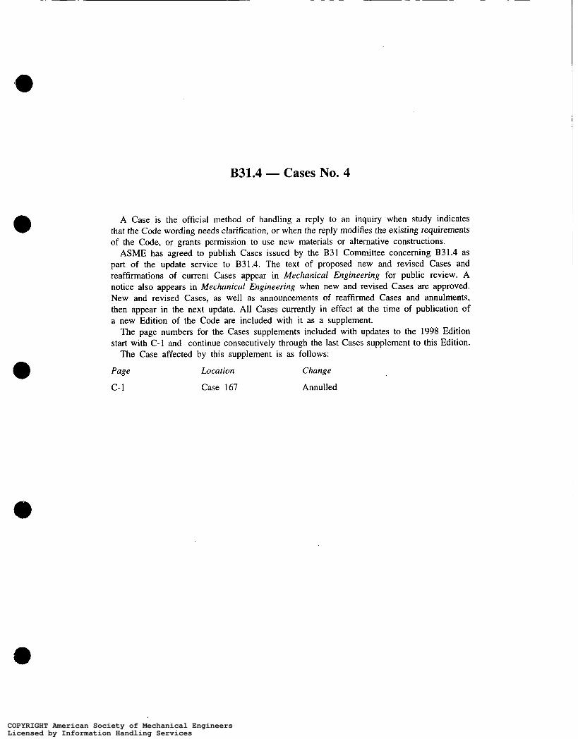
B31.4 - Cases No. 4
A Case is the official method of handling a reply to an inquiry when study indicates that the Code wording needs clarification, or when the reply modifies the existing requirements of the Code, or grants permission to use new materials or alternative constructions.
ASME has agreed to publish Cases issued by the B31 Committee concerning B31.4 as part of the update service to B31.4. The text of proposed new and revised Cases and reaffirmations of current Cases appear in Mechanical Engineering for public review. A notice also appears in Mechanical Engineering when new and revised Cases are approved. New and revised Cases, as well as announcements of reaffirmed Cases and annulments, then appear in the next update. All Cases currently in effect at the time of publication of a new Edition of the Code are included with it as a supplement.
The page numbers for the Cases supplements included with updates to the 1998 Edition start with C-1 and continue consecutively through the last Cases supplement to this Edition.
The Case affected by this supplement is as follows:
Page Location Change
c - 1 Case 167 Annulled
COPYRIGHT American Society of Mechanical EngineersLicensed by Information Handling ServicesCOPYRIGHT American Society of Mechanical EngineersLicensed by Information Handling Services