adsorption-induced deformation of hierarchically...
TRANSCRIPT
Adsorption-Induced Deformation of Hierarchically StructuredMesoporous SilicaEffect of Pore-Level AnisotropyChristian Balzer,*,† Anna M. Waag,† Stefan Gehret,† Gudrun Reichenauer,*,† Florian Putz,‡
Nicola Husing,‡ Oskar Paris,§ Noam Bernstein,¶ Gennady Y. Gor,*,⊥ and Alexander V. Neimark*,∥
†Bavarian Center for Applied Energy Research, Magdalene-Schoch-Str. 3, 97074 Wuerzburg, Germany‡Materials Chemistry, Paris Lodron University Salzburg, Jakob-Haringer Str. 2a, 5020 Salzburg, Austria§Institute of Physics, Montanuniversitaet Leoben, Franz-Josef-Str. 18, 8700 Leoben, Austria¶Center for Materials Physics and Technology, U.S. Naval Research Laboratory, Washington, D.C. 20375, United States⊥Otto H. York Department of Chemical, Biological, and Pharmaceutical Engineering, New Jersey Institute of Technology, UniversityHeights, Newark, New Jersey 07102, United States∥Department of Chemical and Biochemical Engineering, Rutgers, The State University of New Jersey, 98 Brett Road, Piscataway, NewJersey 08854, United States
*S Supporting Information
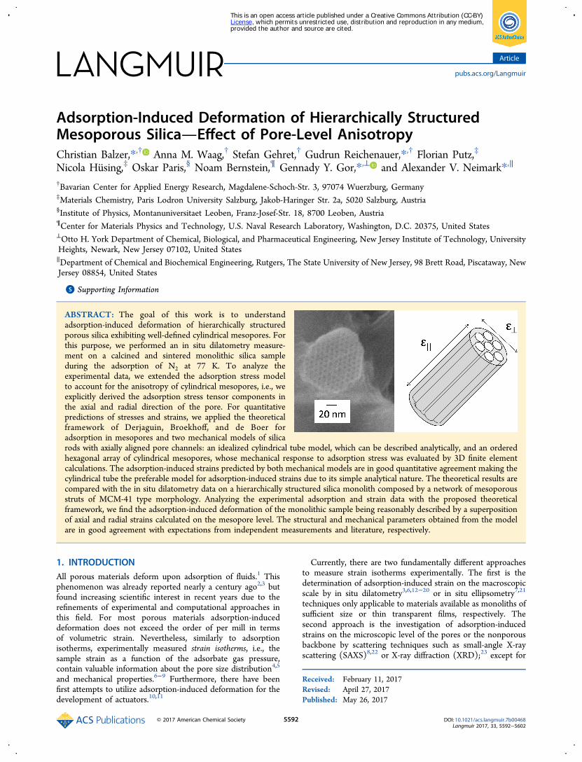
ABSTRACT: The goal of this work is to understandadsorption-induced deformation of hierarchically structuredporous silica exhibiting well-defined cylindrical mesopores. Forthis purpose, we performed an in situ dilatometry measure-ment on a calcined and sintered monolithic silica sampleduring the adsorption of N2 at 77 K. To analyze theexperimental data, we extended the adsorption stress modelto account for the anisotropy of cylindrical mesopores, i.e., weexplicitly derived the adsorption stress tensor components inthe axial and radial direction of the pore. For quantitativepredictions of stresses and strains, we applied the theoreticalframework of Derjaguin, Broekhoff, and de Boer foradsorption in mesopores and two mechanical models of silicarods with axially aligned pore channels: an idealized cylindrical tube model, which can be described analytically, and an orderedhexagonal array of cylindrical mesopores, whose mechanical response to adsorption stress was evaluated by 3D finite elementcalculations. The adsorption-induced strains predicted by both mechanical models are in good quantitative agreement making thecylindrical tube the preferable model for adsorption-induced strains due to its simple analytical nature. The theoretical results arecompared with the in situ dilatometry data on a hierarchically structured silica monolith composed by a network of mesoporousstruts of MCM-41 type morphology. Analyzing the experimental adsorption and strain data with the proposed theoreticalframework, we find the adsorption-induced deformation of the monolithic sample being reasonably described by a superpositionof axial and radial strains calculated on the mesopore level. The structural and mechanical parameters obtained from the modelare in good agreement with expectations from independent measurements and literature, respectively.
1. INTRODUCTIONAll porous materials deform upon adsorption of fluids.1 Thisphenomenon was already reported nearly a century ago2,3 butfound increasing scientific interest in recent years due to therefinements of experimental and computational approaches inthis field. For most porous materials adsorption-induceddeformation does not exceed the order of per mill in termsof volumetric strain. Nevertheless, similarly to adsorptionisotherms, experimentally measured strain isotherms, i.e., thesample strain as a function of the adsorbate gas pressure,contain valuable information about the pore size distribution4,5
and mechanical properties.6−9 Furthermore, there have beenfirst attempts to utilize adsorption-induced deformation for thedevelopment of actuators.10,11
Currently, there are two fundamentally different approachesto measure strain isotherms experimentally. The first is thedetermination of adsorption-induced strain on the macroscopicscale by in situ dilatometry3,6,12−20 or in situ ellipsometry7,21
techniques only applicable to materials available as monoliths ofsufficient size or thin transparent films, respectively. Thesecond approach is the investigation of adsorption-inducedstrains on the microscopic level of the pores or the nonporousbackbone by scattering techniques such as small-angle X-rayscattering (SAXS)8,22 or X-ray diffraction (XRD);23 except for
Received: February 11, 2017Revised: April 27, 2017Published: May 26, 2017
Article
pubs.acs.org/Langmuir
© 2017 American Chemical Society 5592 DOI: 10.1021/acs.langmuir.7b00468Langmuir 2017, 33, 5592−5602
This is an open access article published under a Creative Commons Attribution (CC-BY)License, which permits unrestricted use, distribution and reproduction in any medium,provided the author and source are cited.
large deformations,24 this approach requires materials withordered porosity or crystalline substructure exhibiting clearscattering peaks, whose shift can be interpreted as strain.Examples where both techniques can be applied to the samematerial are very rare;25,26 however, the available results clearlyindicate that adsorption-induced deformation is not necessarilyan isotropic effect but (depending on the sample’s structuraland mechanical properties) may be significantly anisotropic.This finding is also supported by a recent dilatometric study ona thin membrane with oriented mesopores.27
With respect to the theoretical understanding of adsorption-induced deformation, a considerable number of studies wereperformed in recent years, e.g., refs 4, 5, and 28−50. One of theprevailing concepts in these studies is the adsorption stressapproach proposed by Ravikovitch and Neimark;29 it was usedto elucidate the specifics of adsorption-induced deformation ofzeolites,29 carbons,5,34,39 metal−organic frameworks,40 andmesoporous solids.38,43 Although the adsorption stressapproach was instrumental for revealing the mechanism ofadsorption deformation in pores of different size, it was tacitlyassumed that the sample deformation is caused by the stressoriented normal to the pore walls. Contrary, the change of theadsorbent’s surface energy during the adsorption process causestangential stress in the pore walls; this effect is commonlyknown as Bangham’s ef fect or Bangham’s law (see originalwork51 and additions49,52). With this in mind, the adsorptionstress model correctly describes the isotropic pore geometry ofa sphere, since there stresses orientated normal and tangentialto the pore wall are unequivocally correlated. However, foranisotropic pore geometries such as cylindrical or slit-shapedpores, tangential stresses and normal stresses need to beindividually addressed. For the particular case of cylindricalpores, one should therefore expect two different deformationcomponents: one oriented in the radial plane of the pore aspredicted by the adsorption stress model,38 and another andlikely different one in the axial direction of the pore. Supportfor the concept of anisotropic stress in nanopores was alsogiven by recent computational studies on the adsorption inmicropores.53−57
Given the experimental and theoretical evidence foranisotropic stress in nanopores two questions arise: (i) whatkind of adsorption-induced deformation should one expectfrom an anisotropic pore geometry, if stresses oriented normaland tangential to the pore wall are properly considered? (ii)how should experimental data on adsorption-induced deforma-tion be analyzed, if the sample investigated exhibits anisotropicpore geometry? In this work we aim to answer these questionsfor the particular case of a hierarchical structured porous silicawith well-defined cylindrical mesopores (section 2.1), whosedeformation during N2 adsorption at 77 K was measured by insitu dilatometry (section 2.2). The key of our proposedapproach is the extension of the adsorption stress model forcylindrical mesopores with calculation of radial and axialstresses within the framework of Derjaguin, Broekhoff, and deBoer theory (section 3.1).58−60 The calculated stresses serve asinput quantities for mechanical modeling of mesoporous
structures (section 3.2). Here we consider two structuralmodels: (a) simplistic model of an individual cylindrical tubeand (b) 3D array of hexagonally ordered cylindrical porestypical for MCM-41,61 SBA-15,62 or hierarchical structuredsilicas.63 The latter model is investigated by three-dimensionalfinite element calculations. Finally, the proposed theoreticalapproach is applied to the experimental data (section 4).
2. EXPERIMENTAL METHODS2.1. Model SystemSynthesis and Characterization. The
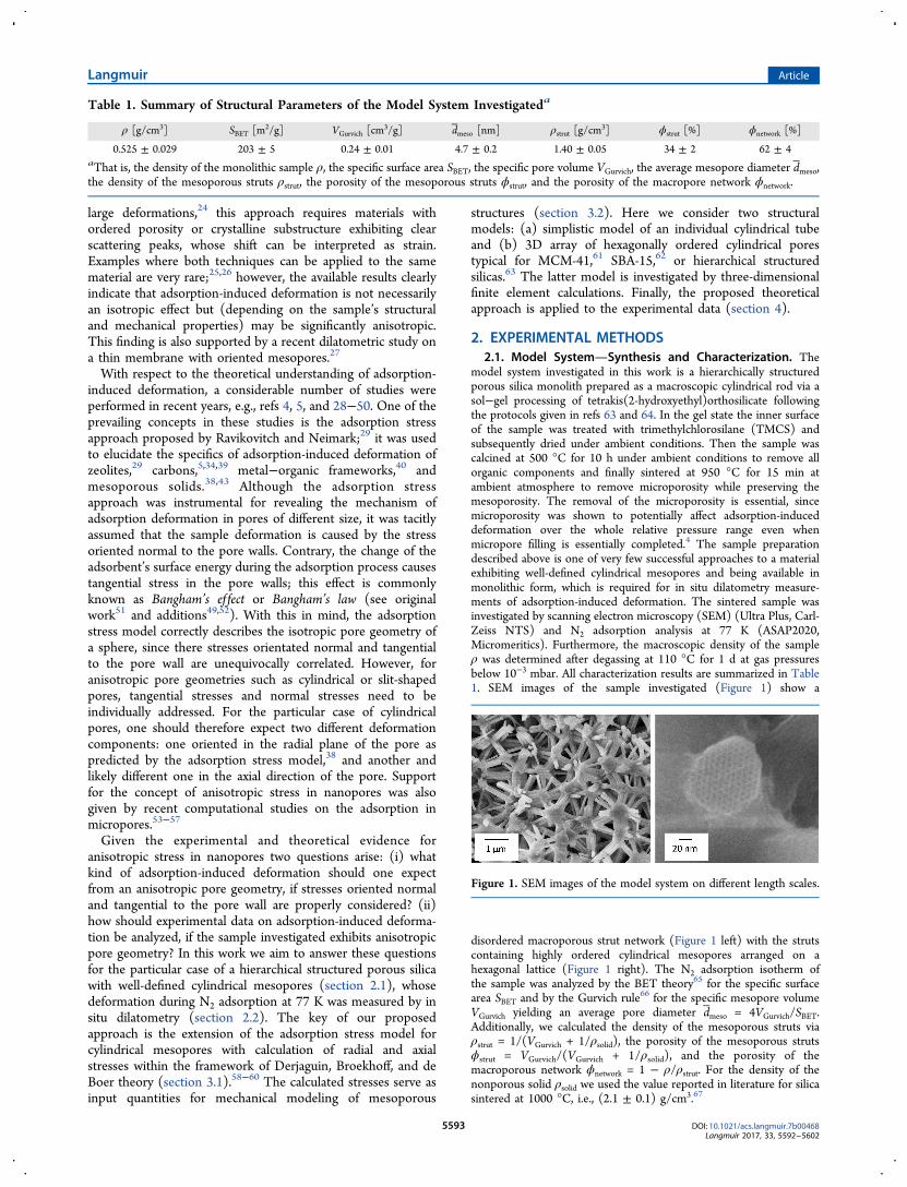
model system investigated in this work is a hierarchically structuredporous silica monolith prepared as a macroscopic cylindrical rod via asol−gel processing of tetrakis(2-hydroxyethyl)orthosilicate followingthe protocols given in refs 63 and 64. In the gel state the inner surfaceof the sample was treated with trimethylchlorosilane (TMCS) andsubsequently dried under ambient conditions. Then the sample wascalcined at 500 °C for 10 h under ambient conditions to remove allorganic components and finally sintered at 950 °C for 15 min atambient atmosphere to remove microporosity while preserving themesoporosity. The removal of the microporosity is essential, sincemicroporosity was shown to potentially affect adsorption-induceddeformation over the whole relative pressure range even whenmicropore filling is essentially completed.4 The sample preparationdescribed above is one of very few successful approaches to a materialexhibiting well-defined cylindrical mesopores and being available inmonolithic form, which is required for in situ dilatometry measure-ments of adsorption-induced deformation. The sintered sample wasinvestigated by scanning electron microscopy (SEM) (Ultra Plus, Carl-Zeiss NTS) and N2 adsorption analysis at 77 K (ASAP2020,Micromeritics). Furthermore, the macroscopic density of the sampleρ was determined after degassing at 110 °C for 1 d at gas pressuresbelow 10−3 mbar. All characterization results are summarized in Table1. SEM images of the sample investigated (Figure 1) show a
disordered macroporous strut network (Figure 1 left) with the strutscontaining highly ordered cylindrical mesopores arranged on ahexagonal lattice (Figure 1 right). The N2 adsorption isotherm ofthe sample was analyzed by the BET theory65 for the specific surfacearea SBET and by the Gurvich rule66 for the specific mesopore volumeVGurvich yielding an average pore diameter dmeso = 4VGurvich/SBET.Additionally, we calculated the density of the mesoporous struts viaρstrut = 1/(VGurvich + 1/ρsolid), the porosity of the mesoporous strutsϕstrut = VGurvich/(VGurvich + 1/ρsolid), and the porosity of themacroporous network ϕnetwork = 1 − ρ/ρstrut. For the density of thenonporous solid ρsolid we used the value reported in literature for silicasintered at 1000 °C, i.e., (2.1 ± 0.1) g/cm3.67
Table 1. Summary of Structural Parameters of the Model System Investigateda
ρ [g/cm3] SBET [m2/g] VGurvich [cm3/g] dmeso [nm] ρstrut [g/cm
3] ϕstrut [%] ϕnetwork [%]
0.525 ± 0.029 203 ± 5 0.24 ± 0.01 4.7 ± 0.2 1.40 ± 0.05 34 ± 2 62 ± 4aThat is, the density of the monolithic sample ρ, the specific surface area SBET, the specific pore volume VGurvich, the average mesopore diameter dmeso,the density of the mesoporous struts ρstrut, the porosity of the mesoporous struts ϕstrut, and the porosity of the macropore network ϕnetwork.
Figure 1. SEM images of the model system on different length scales.
Langmuir Article
DOI: 10.1021/acs.langmuir.7b00468Langmuir 2017, 33, 5592−5602
5593
2.2. In Situ Dilatometry. The in situ dilatometry measurementswere performed with a setup consisting of a commercial adsorptioninstrument (ASAP2020, Micromeritics) and a self-designed sampleholder with a built-in dilatometer. Details of the setup are given in refs5, 20, and 26. It provides the common adsorption isothermcomplemented by a strain isotherm εdil(p/p0), i.e., the relative linearlength change of the monolithic sample as a function of the relative gaspressure p/p0. The absolute accuracy of the dilatometric setup is about±0.2 μm corresponding to a strain resolution of ±1.7 × 10⁻⁵ for thesample of length L0 = 1.2 cm investigated in this work. Prior to themeasurement the sample was degassed at 110 °C for 1 day inside thesample holder to avoid contact of the sample with the ambientatmosphere between degassing and measurement. The analysis gasused was N2 of purity 5.0. During the measurement, the sample holderwas placed in a liquid nitrogen bath and the respective saturationpressure of the analysis gas was measured at regular intervals.
3. THEORETICAL METHODS3.1. Adsorption-Induced Stress. When fluid is adsorbed inside a
pore, it exerts pressure on the pore walls and causes deformation of thesolid matrix, i.e., the nonporous solid backbone. To quantify for thiseffect, Ravikovitch and Neimark29 introduced the volumetricadsorption stress σa defined as the derivative of the grandthermodynamic potential of adsorbed fluid, Ωa, with respect to thepore volume, Vp, at given temperature T and adsorbate chemicalpotential μ:
σ = −∂Ω∂
μV
T
aa
p , (1)
The grand thermodynamic potential of the adsorbed fluid,Ωa(μ,Vp,T), is related to the amount adsorbed Na(μ,Vp,T) by theGibbs equation,68
∫μ μ μ μΩ = Ω − ′ ′μ
μV T V T N V T( , , ) ( , , ) ( , , )da p r p a p
r (2)
Here μr is the chemical potential of the reference state that definesrelative strains and respective stresses. The standard reference statesare the dry state at μr → −∞ and wet or saturated state at μr = 0; thechemical potential is reckoned from the state of liquid−vaporequilibrium at given temperature. Assuming that the bulk adsorbatebehaves like an ideal gas at experimental conditions μ = RgT ln(p/p0)holds with Rg the gas constant, p the gas pressure of the adsorbate, andp0 the respective saturation pressure.In this work, we consider adsorption-induced deformation of
materials with geometrically well-defined and ordered cylindricalpores. The cylindrical shape implies inherent anisotropy of the stresstensor, and in order to account for this anisotropy, we have todifferentiate between the radial (normal) σa,⊥ and axial (tangential) σa,∥components of the adsorption stress tensor, which for the cylindricalpore of radius R, length L, and consequently volume Vp = πR2L, aredefined as
σπ
= −∂Ω∂
= −∂Ω∂
μ μ⊥ V RL R
12
T L T La,
a
p , ,
a
, , (3)
σπ
= −∂Ω∂
= −∂Ω∂
μ μV R L1
a
T R T R,
a
p , ,2
a
, , (4)
While the adsorption isotherm and, respectively, the grand potentialdepend nontrivially on the pore radius, the length of the pore, which isassumed to be significantly larger than the pore radius (L/R ≫ 1),does not affect the fluid density, so that Ωa(μ,Vp,T), is proportional toL. As such, eq 4 can be transformed into
σπ
= −Ω
= −Ω
R L Va,a2
a
p (5)
Equation 5 implies that the pore wall deformation in axial directiondoes not affect the adsorption potential and, respectively, the densityof adsorbed fluid. For a discussion of the limitations of this assumptionsee a recent publication.49
In order to explicitly calculate the adsorption stress, one needs toknow the adsorption isotherm for a pore of given geometry, which canbe determined by various means: by theoretical models such asLangmuir,69 Dubinin,70 or Derjaguin−Broekhoff−de Boer(DBdB)58−60 equations as well as by molecular simulations basedon density functional theory (e.g., refs 29, 43) or Monte Carlomethods (e.g., 27, 34, 39). Following our earlier work,38 here we applythe DBdB theory of capillary condensation, since it offers an analyticalsolution for the entire adsorption process in mesopores including thetransitions between film and filled pore state, i.e., capillarycondensation and evaporation, respectively. According to DBdBtheory, adsorption in a cylindrical mesopore is described by theequivalence of the chemical potential of adsorbed and gaseous phasefor given temperature and relative gas pressure p/p0:
μγ
= = − Π +−
⎡⎣⎢
⎤⎦⎥R T p p V h
R hln( / ) ( )g 0 L
lv
(6)
Here VL is the molar volume of the adsorbate in liquid form, h is thefilm thickness of the adsorbed phase, γlv is the liquid−vapor surfaceenergy, and Π(h) is the disjoining pressure of the adsorbed film, whichis usually determined on a macroporous reference material.
The critical film thickness hc at which capillary condensation occursis given by
γΠ +−
==
hh R h
d ( )d ( )
0h h
lv
c2
c (7)
The film thickness for equilibrium capillary evaporation he is givenby the Derjaguin equation:
∫γ= −
−+
−− ′ Π ′ ′
⎡⎣⎢
⎤⎦⎥R T p p V
R h R hR h h hln( / ) 2
1( )
( ) ( )dh
R
g e 0 Llv
e e2
e
(8)
Here pe is the gas pressure corresponding to he according to eq 6.The molar amount adsorbed Na in film and filled pore regime,
respectively, is given for a single cylindrical pore by
π= −NL
VRh h(2 )a,film
L
2
(9a)
π=NR LVa,filled
2
L (9b)
where the correlation of h and p/p0 follows again from eq 6.As was shown in ref 38, the combination of eq 3 with the framework
of the DBdB theory leads to the following expressions for the radialstress σa,⊥ in the film and filled pore regime of a cylindrical mesopore,respectively:
∫σγ
γγ
γ
= − − Π + Π ′ ′
−−
− = − −−
−
⊥
⎡⎣⎢
⎤⎦⎥
⎡⎣⎢
⎤⎦⎥
RhR
hR
h h
R h R
h
R R h R
( )1
( ) d
1 1 ( ) 1 1
a
h
, ,films
0
lvsv
lv (10a)
∫
σγ
γ γ
= − + +
= − + + − Π + +
⊥ Rp
R T
Vp p
R R RR h h h p p
ln( / )
1( ) ( ) d
a
R
, ,filledsl
0g
L0
s lv2 0 0 cap
(10b)
Here γs is the surface energy of the dry solid under vacuum conditions,γsl the surface energy of the wet solid in contact with liquid, and γsv thesurface energy of the solid covered by an adsorption film of thicknessh. The reduction of the solid surface energy by the adsorption process
Langmuir Article
DOI: 10.1021/acs.langmuir.7b00468Langmuir 2017, 33, 5592−5602
5594
∫γ γ− = − Π ′ ′ + Πh h h h h( ) ( ) d ( )h
s sv 0 (11)
applied in eq 10a follows from the Gibbs adsorption equation for a flatsurface38 and (γs − γsv(h))/R is the corresponding stress due toBangham’s law38,71 causing monotonic expansion with progressingadsorption. Counteracting the Bangham stress is the Laplace pressureγlv(1/(R − h) − 1/R) resulting from the curved liquid vapor interface,which is numerically smaller than the Bangham stress in most cases.Additionally, in the filled pore state (eq 10b) the pore is subjected toRgT/VL ln(p/p0), i.e., the classical capillary pressure pcap. For thesecond equality in eq 10b, the Frumkin−Derjaguin (FD) equation(see, e.g., refs 72 and 73) for the cylindrical pore geometry is appliedto correlate γs and γsl (for details, see the Supporting Information(SI)):
∫γ γ γ= + + − ΠR
R h h h1
( ) ( ) dR
s sl lv 0 (12)
In direct analogy to eq 10, the combination of eq 5 and DBdBtheory yields the axial (tangential) stress σa,∥ inside the cylindricalmesopore (for details, see the SI):
∫
∫
σγ
γ γ γ
= − + − ′ Π ′ ′ − − Π
−−
= − + Π −−
− ′Π ′ ′
⎜ ⎟⎛⎝
⎞⎠R R
R h h hhR
hR
h
hR R h
h
RhR
hhR R h
Rh h h
2 2( ) ( ) d 2 ( )
2 ( )( )
2( ) d
h
h
a, ,films
2 0
2
2lv sv
2
2
2
2lv
2 0 (13a)
∫
σγ γ γ
= − + + = − +
+ − Π + +
Rp
R T
Vp p
R R
RR h h h p p
2ln( / )
2 2
2( ) ( ) d
R
a, ,filledsl
0g
L0
s lv
2 0 0 cap (13b)
The quantitatively dominant term in eq 13a is 2γsv(h)/Rcorresponding to an axial Bangham stress twice as large as in radialdirection (eq 10a). Notably the factor of 2 between Bangham stress inaxial and radial direction is intrinsic to the cylindrical geometry andwas already reported in previous works, e.g., ref 71. In the filled poreregime both stresses σa,⊥,filled and σa,∥,filled (eq 10b and 13b,respectively) are found to be directly proportional to pcap fitting theconcept of an isostatic capillary pressure. However, axial and radialstress in the filled pore regime are shifted relative to one another by aconstant offset γsl/R, which again is a result of the cylindrical geometryof the pore. It is important to note that the equality of eq 13a and bdescribes the equilibrium of grand potential in film and filled pore state(see eq 5) and therefore corresponds to the condition of capillaryevaporation.58 If the surface energy difference γs − γsl between dry andwet solid is taken from the modified FD equation (eq 12), the equalityof eq 13a and b results in the Derjaguin equation (eq 8), which impliesp0 ≪ pcap(pe/p0).3.2. Mechanical Models for Porous Struts with Cylindrical
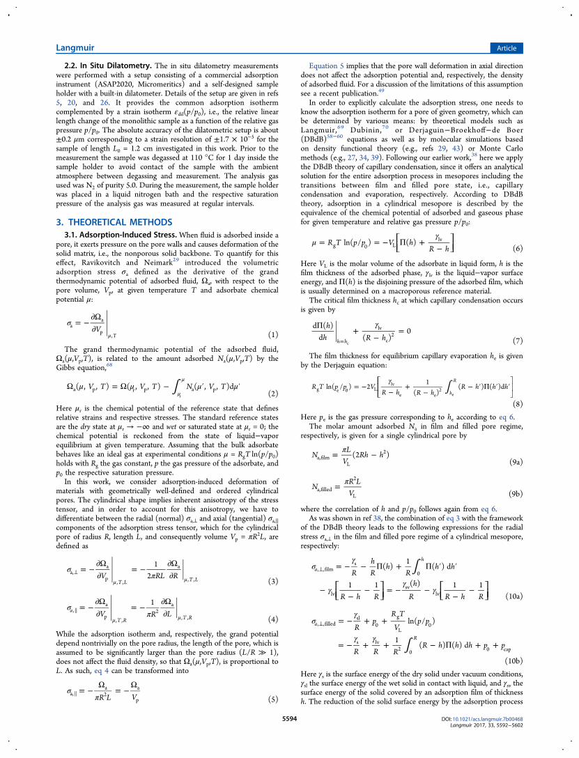
Pores. As the simplest model describing the deformation of a porousstrut with aligned cylindrical mesopores (Figure 1), we consider acylindrical tube of inner radius R, outer radius Rout and thereforeporosity ϕ = R2/Rout
2 (Figure 2). This model simplistically representsa unit cell in the strut’s pore arrangement shown in Figure 1.For comparison with experimental data the potentially relevant
deformations of the cylindrical tube are the axial strain, i.e. the relativeelongation of the tube εa,∥ = δL/L, the circumferential strain, i.e. therelative change of the outer radius εa,⊥ = δRout/Rout , and thevolumetric strain, i.e., the relative change εa,vol of volume occupied bytube and pore. The sought strains follow from the solution of theLame problem with boundary conditions provided by the radial(normal) σa,⊥ and axial (tangential) σa,∥ components of the adsorptionstress (for details, see the SI):74,75
ε δ ϕϕ
σ νσ= =−
−⊥ ⊥R RE
/1
1(2 )a, out out a, a,
(14)
ε δ ϕϕ
σ νσ= =−
− ⊥L LE
/1
1( 2 )a, a, a,
(15)
ε ε ε ϕϕ
ν σ ν σ= + =−
− + −⊥ ⊥E2
11
[2(2 ) (1 2 ) ]a,vol a, a, a, a,
(16)
Here E and ν are the Young’s modulus and the Poisson’s ratio of thenonporous solid forming the cylindrical tube, respectively. Notably,above equations imply an isotropic and elastic solid, i.e., E and ν aredirectional and strain independent constants. For eq 16 it wasfurthermore assumed that axial and circumferential strains aresignificantly smaller than 1, which is a reasonable approximation formost adsorbate−adsorbent combinations.
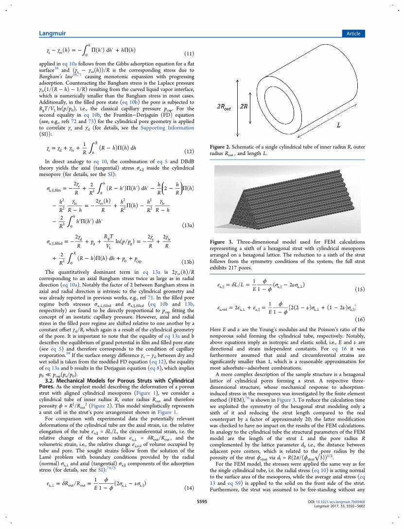
A more complex description of the sample structure is a hexagonallattice of cylindrical pores forming a strut. A respective three-dimensional structure, whose mechanical response to adsorption-induced stress in the mesopores was investigated by the finite elementmethod (FEM),76 is shown in Figure 3. To reduce the calculation timewe exploited the symmetry of the hexagonal strut modeling only asixth of it and reducing the strut length compared to the realcounterpart by a factor of approximately 20; the latter modificationwas checked to have no impact on the results of the FEM calculations.In analogy to the cylindrical tube the structural parameters of the FEMmodel are the length of the strut L and the pore radius Rcomplemented by the lattice parameter dl, i.e., the distance betweenadjacent pore centers, which is related to the pore radius by theporosity of the strut ϕstrut via dl = R(2π/(ϕstrut√3))1/2.
For the FEM model, the stresses were applied the same way as forthe single cylindrical tube, i.e. the radial stress (eq 10) is acting normalto the surface area of the mesopores, while the average axial stress (eq13 and eq S9) is applied to the solid on the front side of the strut.Furthermore, the strut was assumed to be free-standing without any
Figure 2. Schematic of a single cylindrical tube of inner radius R, outerradius Rout , and length L.
Figure 3. Three-dimensional model used for FEM calculationsrepresenting a sixth of a hexagonal strut with cylindrical mesoporesarranged on a hexagonal lattice. The reduction to a sixth of the strutfollows from the symmetry conditions of the system; the full strutexhibits 217 pores.
Langmuir Article
DOI: 10.1021/acs.langmuir.7b00468Langmuir 2017, 33, 5592−5602
5595
confinement whatsoever. As for the cylindrical tube mechanicalproperties of the nonporous solid phase, E and ν, are assumed to beconstant and isotropic. The FEM calculations were performed with thecommercial software SOLIDWORKS 2011. The results evaluatedfrom the output of the FEM calculations are the average strain of thestrut length δL/L corresponding to εa,∥ (eq 15) and the average strainof the lattice parameter δdl/dl corresponding to εa,⊥ (eq 14). Notably,to minimize boundary effects we evaluated δdl/dl only for poresexhibiting six neighboring pores. Furthermore, we investigated thedependence of the strain δdl/dl on the number of pores within thestrut: in the range of 127 to 217 pores the relative deviations of δdl/dlwere below 0.2%. The applied model is therefore consideredsufficiently large to effectively exclude boundary effects.
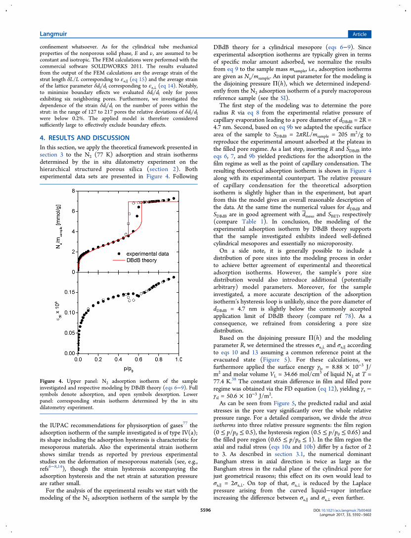
4. RESULTS AND DISCUSSIONIn this section, we apply the theoretical framework presented insection 3 to the N2 (77 K) adsorption and strain isothermsdetermined by the in situ dilatometry experiment on thehierarchical structured porous silica (section 2). Bothexperimental data sets are presented in Figure 4. Following
the IUPAC recommendations for physisorption of gases77 theadsorption isotherm of the sample investigated is of type IV(a);its shape including the adsorption hysteresis is characteristic formesoporous materials. Also the experimental strain isothermshows similar trends as reported by previous experimentalstudies on the deformation of mesoporous materials (see, e.g.,refs6−8,14), though the strain hysteresis accompanying theadsorption hysteresis and the net strain at saturation pressureare rather small.For the analysis of the experimental results we start with the
modeling of the N2 adsorption isotherm of the sample by the
DBdB theory for a cylindrical mesopore (eqs 6−9). Sinceexperimental adsorption isotherms are typically given in termsof specific molar amount adsorbed, we normalize the resultsfrom eq 9 to the sample mass msample, i.e., adsorption isothermsare given as Na/msample. An input parameter for the modeling isthe disjoining pressure Π(h), which we determined independ-ently from the N2 adsorption isotherm of a purely macroporousreference sample (see the SI).The first step of the modeling was to determine the pore
radius R via eq 8 from the experimental relative pressure ofcapillary evaporation leading to a pore diameter of dDBdB = 2R =4.7 nm. Second, based on eq 9b we adapted the specific surfacearea of the sample to SDBdB = 2πRL/msample = 205 m2/g toreproduce the experimental amount adsorbed at the plateau inthe filled pore regime. As a last step, inserting R and SDBdB intoeqs 6, 7, and 9b yielded predictions for the adsorption in thefilm regime as well as the point of capillary condensation. Theresulting theoretical adsorption isotherm is shown in Figure 4along with its experimental counterpart. The relative pressureof capillary condensation for the theoretical adsorptionisotherm is slightly higher than in the experiment, but apartfrom this the model gives an overall reasonable description ofthe data. At the same time the numerical values for dDBdB andSDBdB are in good agreement with dmeso and SBET, respectively(compare Table 1). In conclusion, the modeling of theexperimental adsorption isotherm by DBdB theory supportsthat the sample investigated exhibits indeed well-definedcylindrical mesopores and essentially no microporosity.On a side note, it is generally possible to include a
distribution of pore sizes into the modeling process in orderto achieve better agreement of experimental and theoreticaladsorption isotherms. However, the sample’s pore sizedistribution would also introduce additional (potentiallyarbitrary) model parameters. Moreover, for the sampleinvestigated, a more accurate description of the adsorptionisotherm’s hysteresis loop is unlikely, since the pore diameter ofdDBdB = 4.7 nm is slightly below the commonly acceptedapplication limit of DBdB theory (compare ref 78). As aconsequence, we refrained from considering a pore sizedistribution.Based on the disjoining pressure Π(h) and the modeling
parameter R, we determined the stresses σa,⊥ and σa,∥ accordingto eqs 10 and 13 assuming a common reference point at theevacuated state (Figure 5). For these calculations, wefurthermore applied the surface energy γlv = 8.88 × 10⁻³ J/m2 and molar volume VL = 34.66 mol/cm3 of liquid N2 at T =77.4 K.38 The constant strain difference in film and filled poreregime was obtained via the FD equation (eq 12), yielding γs −γsl = 50.6 × 10⁻³ J/m2.As can be seen from Figure 5, the predicted radial and axial
stresses in the pore vary significantly over the whole relativepressure range. For a detailed comparison, we divide the stressisotherms into three relative pressure segments: the film region(0 ≤ p/p0 ≤ 0.5), the hysteresis region (0.5 ≤ p/p0 ≤ 0.65) andthe filled pore region (0.65 ≤ p/p0 ≤ 1). In the film region theaxial and radial stress (eqs 10a and 10b) differ by a factor of 2to 3. As described in section 3.1, the numerical dominantBangham stress in axial direction is twice as large as theBangham stress in the radial plane of the cylindrical pore forjust geometrical reasons; this effect on its own would lead toσa,∥ = 2σa,⊥. On top of that, σa,⊥ is reduced by the Laplacepressure arising from the curved liquid−vapor interfaceincreasing the difference between σa,∥ and σa,⊥ even further.
Figure 4. Upper panel: N2 adsorption isotherm of the sampleinvestigated and respective modeling by DBdB theory (eqs 6−9). Fullsymbols denote adsorption, and open symbols desorption. Lowerpanel: corresponding strain isotherm determined by the in situdilatometry experiment.
Langmuir Article
DOI: 10.1021/acs.langmuir.7b00468Langmuir 2017, 33, 5592−5602
5596
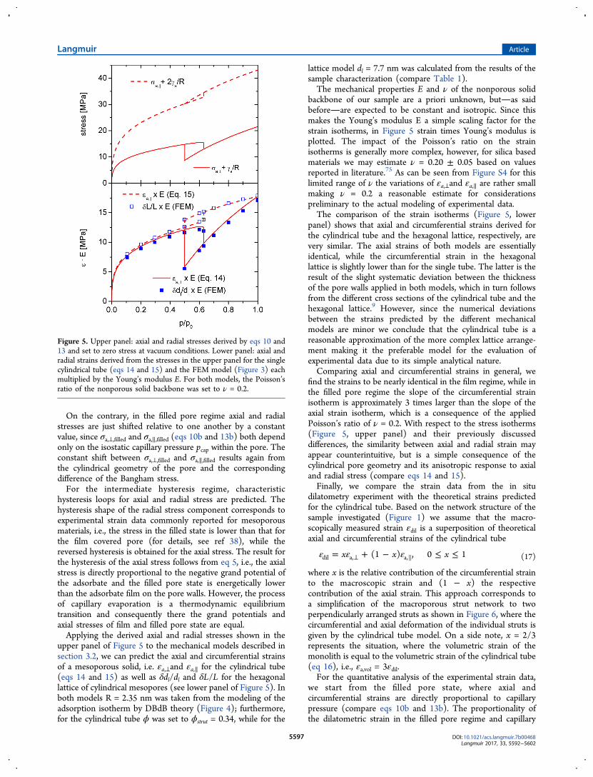
On the contrary, in the filled pore regime axial and radialstresses are just shifted relative to one another by a constantvalue, since σa,⊥,filled and σa,∥,filled (eqs 10b and 13b) both dependonly on the isostatic capillary pressure pcap within the pore. Theconstant shift between σa,⊥,filled and σa,∥,filled results again fromthe cylindrical geometry of the pore and the correspondingdifference of the Bangham stress.For the intermediate hysteresis regime, characteristic
hysteresis loops for axial and radial stress are predicted. Thehysteresis shape of the radial stress component corresponds toexperimental strain data commonly reported for mesoporousmaterials, i.e., the stress in the filled state is lower than that forthe film covered pore (for details, see ref 38), while thereversed hysteresis is obtained for the axial stress. The result forthe hysteresis of the axial stress follows from eq 5, i.e., the axialstress is directly proportional to the negative grand potential ofthe adsorbate and the filled pore state is energetically lowerthan the adsorbate film on the pore walls. However, the processof capillary evaporation is a thermodynamic equilibriumtransition and consequently there the grand potentials andaxial stresses of film and filled pore state are equal.Applying the derived axial and radial stresses shown in the
upper panel of Figure 5 to the mechanical models described insection 3.2, we can predict the axial and circumferential strainsof a mesoporous solid, i.e. εa,⊥and εa,∥ for the cylindrical tube(eqs 14 and 15) as well as δdl/dl and δL/L for the hexagonallattice of cylindrical mesopores (see lower panel of Figure 5). Inboth models R = 2.35 nm was taken from the modeling of theadsorption isotherm by DBdB theory (Figure 4); furthermore,for the cylindrical tube ϕ was set to ϕstrut = 0.34, while for the
lattice model dl = 7.7 nm was calculated from the results of thesample characterization (compare Table 1).The mechanical properties E and ν of the nonporous solid
backbone of our sample are a priori unknown, butas saidbeforeare expected to be constant and isotropic. Since thismakes the Young’s modulus E a simple scaling factor for thestrain isotherms, in Figure 5 strain times Young’s modulus isplotted. The impact of the Poisson’s ratio on the strainisotherms is generally more complex, however, for silica basedmaterials we may estimate ν = 0.20 ± 0.05 based on valuesreported in literature.75 As can be seen from Figure S4 for thislimited range of ν the variations of εa,⊥and εa,∥ are rather smallmaking ν = 0.2 a reasonable estimate for considerationspreliminary to the actual modeling of experimental data.The comparison of the strain isotherms (Figure 5, lower
panel) shows that axial and circumferential strains derived forthe cylindrical tube and the hexagonal lattice, respectively, arevery similar. The axial strains of both models are essentiallyidentical, while the circumferential strain in the hexagonallattice is slightly lower than for the single tube. The latter is theresult of the slight systematic deviation between the thicknessof the pore walls applied in both models, which in turn followsfrom the different cross sections of the cylindrical tube and thehexagonal lattice.9 However, since the numerical deviationsbetween the strains predicted by the different mechanicalmodels are minor we conclude that the cylindrical tube is areasonable approximation of the more complex lattice arrange-ment making it the preferable model for the evaluation ofexperimental data due to its simple analytical nature.Comparing axial and circumferential strains in general, we
find the strains to be nearly identical in the film regime, while inthe filled pore regime the slope of the circumferential strainisotherm is approximately 3 times larger than the slope of theaxial strain isotherm, which is a consequence of the appliedPoisson’s ratio of ν = 0.2. With respect to the stress isotherms(Figure 5, upper panel) and their previously discusseddifferences, the similarity between axial and radial strain mayappear counterintuitive, but is a simple consequence of thecylindrical pore geometry and its anisotropic response to axialand radial stress (compare eqs 14 and 15).Finally, we compare the strain data from the in situ
dilatometry experiment with the theoretical strains predictedfor the cylindrical tube. Based on the network structure of thesample investigated (Figure 1) we assume that the macro-scopically measured strain εdil is a superposition of theoreticalaxial and circumferential strains of the cylindrical tube
ε ε ε= + − ≤ ≤⊥x x x(1 ) , 0 1dil a, a, (17)
where x is the relative contribution of the circumferential strainto the macroscopic strain and (1 − x) the respectivecontribution of the axial strain. This approach corresponds toa simplification of the macroporous strut network to twoperpendicularly arranged struts as shown in Figure 6, where thecircumferential and axial deformation of the individual struts isgiven by the cylindrical tube model. On a side note, x = 2/3represents the situation, where the volumetric strain of themonolith is equal to the volumetric strain of the cylindrical tube(eq 16), i.e., εa,vol = 3εdil.For the quantitative analysis of the experimental strain data,
we start from the filled pore state, where axial andcircumferential strains are directly proportional to capillarypressure (compare eqs 10b and 13b). The proportionality ofthe dilatometric strain in the filled pore regime and capillary
Figure 5. Upper panel: axial and radial stresses derived by eqs 10 and13 and set to zero stress at vacuum conditions. Lower panel: axial andradial strains derived from the stresses in the upper panel for the singlecylindrical tube (eqs 14 and 15) and the FEM model (Figure 3) eachmultiplied by the Young’s modulus E. For both models, the Poisson’sratio of the nonporous solid backbone was set to ν = 0.2.
Langmuir Article
DOI: 10.1021/acs.langmuir.7b00468Langmuir 2017, 33, 5592−5602
5597
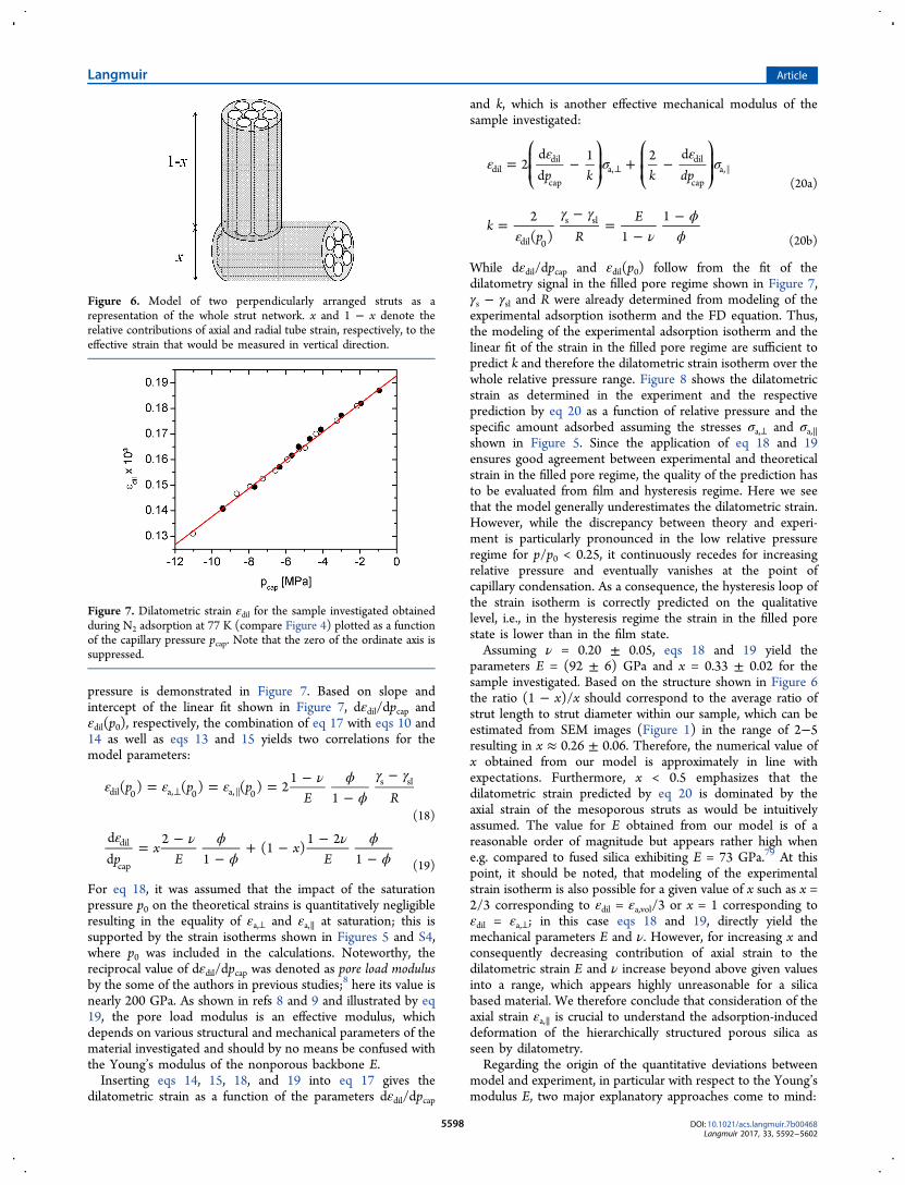
pressure is demonstrated in Figure 7. Based on slope andintercept of the linear fit shown in Figure 7, dεdil/dpcap andεdil(p0), respectively, the combination of eq 17 with eqs 10 and14 as well as eqs 13 and 15 yields two correlations for themodel parameters:
ε ε ε ν ϕϕ
γ γ= = = −
−−
⊥p p pE R
( ) ( ) ( ) 21
1dil 0 a, 0 a, 0s sl
(18)
ε ν ϕϕ
ν ϕϕ
= −−
+ − −−p
xE
xE
dd
21
(1 )1 2
1dil
cap (19)
For eq 18, it was assumed that the impact of the saturationpressure p0 on the theoretical strains is quantitatively negligibleresulting in the equality of εa,⊥ and εa,∥ at saturation; this issupported by the strain isotherms shown in Figures 5 and S4,where p0 was included in the calculations. Noteworthy, thereciprocal value of dεdil/dpcap was denoted as pore load modulusby the some of the authors in previous studies;8 here its value isnearly 200 GPa. As shown in refs 8 and 9 and illustrated by eq19, the pore load modulus is an effective modulus, whichdepends on various structural and mechanical parameters of thematerial investigated and should by no means be confused withthe Young’s modulus of the nonporous backbone E.Inserting eqs 14, 15, 18, and 19 into eq 17 gives the
dilatometric strain as a function of the parameters dεdil/dpcap
and k, which is another effective mechanical modulus of thesample investigated:
εε
σε
σ= − + −⊥
⎛⎝⎜⎜
⎞⎠⎟⎟
⎛⎝⎜⎜
⎞⎠⎟⎟p k k dp
2dd
1 2 ddil
dil
capa,
dil
capa,
(20a)
εγ γ
νϕ
ϕ=
−=
−−
kp R
E2( ) 1
1
dil 0
s sl
(20b)
While dεdil/dpcap and εdil(p0) follow from the fit of thedilatometry signal in the filled pore regime shown in Figure 7,γs − γsl and R were already determined from modeling of theexperimental adsorption isotherm and the FD equation. Thus,the modeling of the experimental adsorption isotherm and thelinear fit of the strain in the filled pore regime are sufficient topredict k and therefore the dilatometric strain isotherm over thewhole relative pressure range. Figure 8 shows the dilatometricstrain as determined in the experiment and the respectiveprediction by eq 20 as a function of relative pressure and thespecific amount adsorbed assuming the stresses σa,⊥ and σa,∥shown in Figure 5. Since the application of eq 18 and 19ensures good agreement between experimental and theoreticalstrain in the filled pore regime, the quality of the prediction hasto be evaluated from film and hysteresis regime. Here we seethat the model generally underestimates the dilatometric strain.However, while the discrepancy between theory and experi-ment is particularly pronounced in the low relative pressureregime for p/p0 < 0.25, it continuously recedes for increasingrelative pressure and eventually vanishes at the point ofcapillary condensation. As a consequence, the hysteresis loop ofthe strain isotherm is correctly predicted on the qualitativelevel, i.e., in the hysteresis regime the strain in the filled porestate is lower than in the film state.Assuming ν = 0.20 ± 0.05, eqs 18 and 19 yield the
parameters E = (92 ± 6) GPa and x = 0.33 ± 0.02 for thesample investigated. Based on the structure shown in Figure 6the ratio (1 − x)/x should correspond to the average ratio ofstrut length to strut diameter within our sample, which can beestimated from SEM images (Figure 1) in the range of 2−5resulting in x ≈ 0.26 ± 0.06. Therefore, the numerical value ofx obtained from our model is approximately in line withexpectations. Furthermore, x < 0.5 emphasizes that thedilatometric strain predicted by eq 20 is dominated by theaxial strain of the mesoporous struts as would be intuitivelyassumed. The value for E obtained from our model is of areasonable order of magnitude but appears rather high whene.g. compared to fused silica exhibiting E = 73 GPa.79 At thispoint, it should be noted, that modeling of the experimentalstrain isotherm is also possible for a given value of x such as x =2/3 corresponding to εdil = εa,vol/3 or x = 1 corresponding toεdil = εa,⊥; in this case eqs 18 and 19, directly yield themechanical parameters E and ν. However, for increasing x andconsequently decreasing contribution of axial strain to thedilatometric strain E and ν increase beyond above given valuesinto a range, which appears highly unreasonable for a silicabased material. We therefore conclude that consideration of theaxial strain εa,∥ is crucial to understand the adsorption-induceddeformation of the hierarchically structured porous silica asseen by dilatometry.Regarding the origin of the quantitative deviations between
model and experiment, in particular with respect to the Young’smodulus E, two major explanatory approaches come to mind:
Figure 6. Model of two perpendicularly arranged struts as arepresentation of the whole strut network. x and 1 − x denote therelative contributions of axial and radial tube strain, respectively, to theeffective strain that would be measured in vertical direction.
Figure 7. Dilatometric strain εdil for the sample investigated obtainedduring N2 adsorption at 77 K (compare Figure 4) plotted as a functionof the capillary pressure pcap. Note that the zero of the ordinate axis issuppressed.
Langmuir Article
DOI: 10.1021/acs.langmuir.7b00468Langmuir 2017, 33, 5592−5602
5598
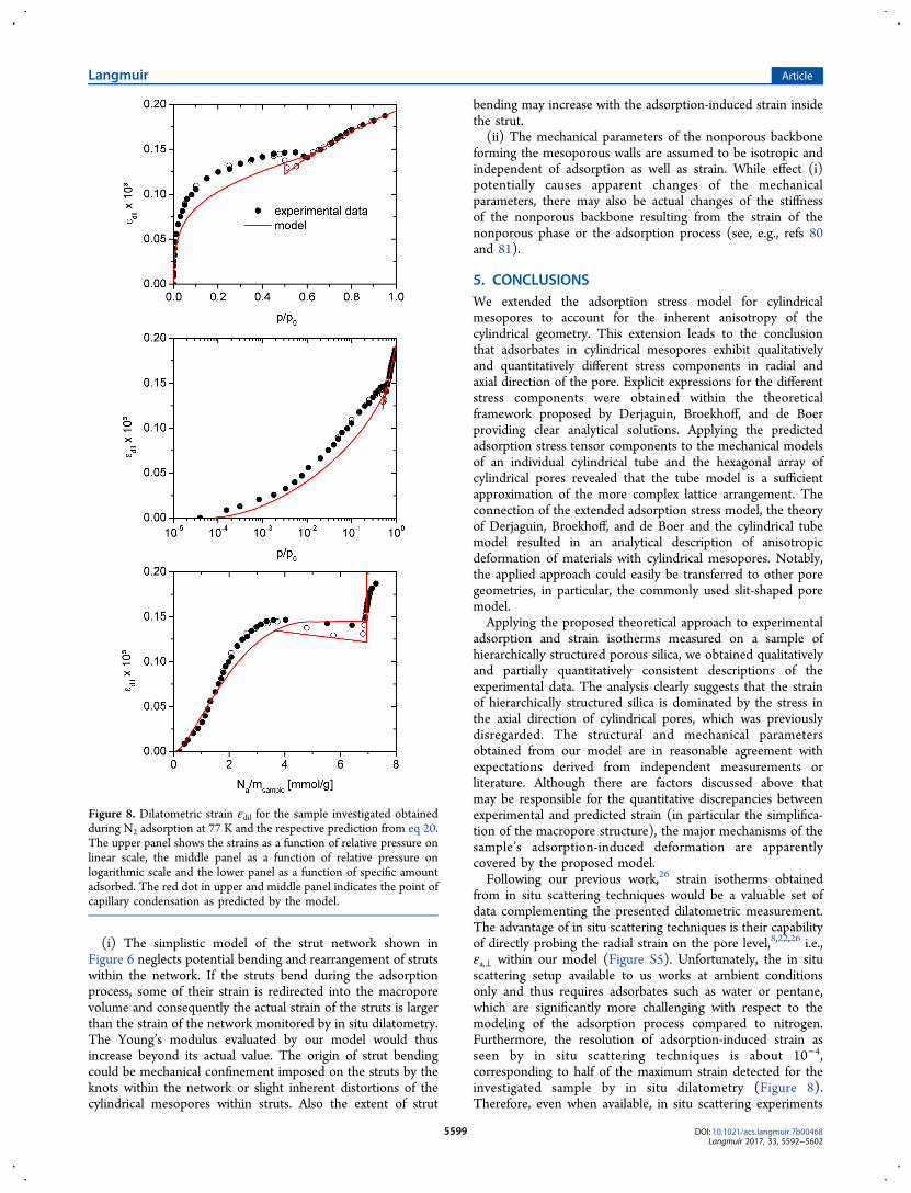
(i) The simplistic model of the strut network shown inFigure 6 neglects potential bending and rearrangement of strutswithin the network. If the struts bend during the adsorptionprocess, some of their strain is redirected into the macroporevolume and consequently the actual strain of the struts is largerthan the strain of the network monitored by in situ dilatometry.The Young’s modulus evaluated by our model would thusincrease beyond its actual value. The origin of strut bendingcould be mechanical confinement imposed on the struts by theknots within the network or slight inherent distortions of thecylindrical mesopores within struts. Also the extent of strut
bending may increase with the adsorption-induced strain insidethe strut.(ii) The mechanical parameters of the nonporous backbone
forming the mesoporous walls are assumed to be isotropic andindependent of adsorption as well as strain. While effect (i)potentially causes apparent changes of the mechanicalparameters, there may also be actual changes of the stiffnessof the nonporous backbone resulting from the strain of thenonporous phase or the adsorption process (see, e.g., refs 80and 81).
5. CONCLUSIONSWe extended the adsorption stress model for cylindricalmesopores to account for the inherent anisotropy of thecylindrical geometry. This extension leads to the conclusionthat adsorbates in cylindrical mesopores exhibit qualitativelyand quantitatively different stress components in radial andaxial direction of the pore. Explicit expressions for the differentstress components were obtained within the theoreticalframework proposed by Derjaguin, Broekhoff, and de Boerproviding clear analytical solutions. Applying the predictedadsorption stress tensor components to the mechanical modelsof an individual cylindrical tube and the hexagonal array ofcylindrical pores revealed that the tube model is a sufficientapproximation of the more complex lattice arrangement. Theconnection of the extended adsorption stress model, the theoryof Derjaguin, Broekhoff, and de Boer and the cylindrical tubemodel resulted in an analytical description of anisotropicdeformation of materials with cylindrical mesopores. Notably,the applied approach could easily be transferred to other poregeometries, in particular, the commonly used slit-shaped poremodel.Applying the proposed theoretical approach to experimental
adsorption and strain isotherms measured on a sample ofhierarchically structured porous silica, we obtained qualitativelyand partially quantitatively consistent descriptions of theexperimental data. The analysis clearly suggests that the strainof hierarchically structured silica is dominated by the stress inthe axial direction of cylindrical pores, which was previouslydisregarded. The structural and mechanical parametersobtained from our model are in reasonable agreement withexpectations derived from independent measurements orliterature. Although there are factors discussed above thatmay be responsible for the quantitative discrepancies betweenexperimental and predicted strain (in particular the simplifica-tion of the macropore structure), the major mechanisms of thesample’s adsorption-induced deformation are apparentlycovered by the proposed model.Following our previous work,26 strain isotherms obtained
from in situ scattering techniques would be a valuable set ofdata complementing the presented dilatometric measurement.The advantage of in situ scattering techniques is their capabilityof directly probing the radial strain on the pore level,8,22,26 i.e.,εa,⊥ within our model (Figure S5). Unfortunately, the in situscattering setup available to us works at ambient conditionsonly and thus requires adsorbates such as water or pentane,which are significantly more challenging with respect to themodeling of the adsorption process compared to nitrogen.Furthermore, the resolution of adsorption-induced strain asseen by in situ scattering techniques is about 10−4,corresponding to half of the maximum strain detected for theinvestigated sample by in situ dilatometry (Figure 8).Therefore, even when available, in situ scattering experiments
Figure 8. Dilatometric strain εdil for the sample investigated obtainedduring N2 adsorption at 77 K and the respective prediction from eq 20.The upper panel shows the strains as a function of relative pressure onlinear scale, the middle panel as a function of relative pressure onlogarithmic scale and the lower panel as a function of specific amountadsorbed. The red dot in upper and middle panel indicates the point ofcapillary condensation as predicted by the model.
Langmuir Article
DOI: 10.1021/acs.langmuir.7b00468Langmuir 2017, 33, 5592−5602
5599
performed for N2 adsorption at 77 K would probably not beable to provide experimental data of sufficient accuracy tovalidate the results presented in this work. Future work willtherefore focus on material−adsorbate combinations exhibitinglarger adsorption-induced strains, which can be investigated byin situ dilatometry and in situ scattering techniques, while stillallowing for the application of the presented theoreticalframework.
■ ASSOCIATED CONTENT*S Supporting InformationThe Supporting Information is available free of charge on theACS Publications website at DOI: 10.1021/acs.lang-muir.7b00468.
Derivation of the Frumkin−Derjaguin equation forcylindrical pores; derivation of the axial stress in thecylindrical pore according to DBdB theory; solution ofthe Lame problem for the cylindrical tube; determinationof the reference isotherm for DBdB theory; dependenceof axial and circumferential strain on the Poisson’s ratio;prediction of strain isotherm from in-situ scattering(PDF)
■ AUTHOR INFORMATIONCorresponding Authors*E-mail: [email protected].*E-mail: [email protected].*E-mail: [email protected].*E-mail: [email protected] Balzer: 0000-0002-6740-0311Gennady Y. Gor: 0000-0001-7455-1778Author ContributionsThe manuscript was written through contributions of allauthors. All authors have given approval to the final version ofthe manuscript.NotesThe authors declare no competing financial interest.
■ ACKNOWLEDGMENTSWe are grateful to Lena Weigold and Cornelia Stark (bothBavarian Center for Applied Energy Research) for their supportin performing the FEM modeling. We also thank RolandMorak, Lukas Ludescher (both Montanuniversitaet Leoben),and Michael Elsaesser (Paris Lodron University Salzburg) forvaluable discussions. All authors except N.B. acknowledgefinancial support from an international program funded by theAustrian Science Foundation FWF (Project I 1605-N20) andthe German Science Foundation DFG (Project RE 1148/10-1)within the framework of the DACH agreement. AVNacknowledges partial support from the NSF Rutgers ERC onstructured organic composite systems. AVN thanks GeorgeScherer (Princeton University) for valuable discussions. Thework of N.B. was supported by Office of Naval Researchthrough the U.S. Naval Research Laboratory's basic researchprogram.
■ REFERENCES(1) Gor, G. Y.; Huber, P.; Bernstein, N. Adsorption-InducedDeformation of Nanoporous Materials - a Review. Appl. Phys. Rev.2017, 4, 011303.
(2) Whipple, F. J. W. The Theory of the Hair Hygrometer. Proc. Phys.Soc. London 1921, 34, i−v.(3) Meehan, F. T. The Expansion of Charcoal on Sorption of CarbonDioxide. Proc. R. Soc. London, Ser. A 1927, 115, 199−207.(4) Balzer, C.; Cimino, R. T.; Gor, G. Y.; Neimark, A. V.;Reichenauer, G. Deformation of Microporous Carbons during N2,Ar, and CO2 Adsorption: Insight from the Density Functional Theory.Langmuir 2016, 32, 8265−8274.(5) Kowalczyk, P.; Balzer, C.; Reichenauer, G.; Terzyk, A. P.;Gauden, P. A.; Neimark, A. V. Using in-situ adsorption dilatometry forassessment of micropore size distribution in monolithic carbons.Carbon 2016, 103, 263−272.(6) Reichenauer, G.; Scherer, G. W. Nitrogen Adsorption inCompliant Materials. J. Non-Cryst. Solids 2000, 277, 162−172.(7) Mogilnikov, K. P.; Baklanov, M. R. Determination of Young’smodulus of porous low-k films by ellipsometric porosimetry.Electrochem. Solid-State Lett. 2002, 5, F29−F31.(8) Prass, J.; Muter, D.; Fratzl, P.; Paris, O. Capillarity-drivendeformation of ordered nanoporous silica. Appl. Phys. Lett. 2009, 95,083121.(9) Gor, G. Y.; Bertinetti, L.; Bernstein, N.; Hofmann, T.; Fratzl, P.;Huber, P. Elastic response of mesoporous silicon to capillary pressuresin the pores. Appl. Phys. Lett. 2015, 106, 261901.(10) Van Opdenbosch, D.; Fritz-Popovski, G.; Wagermaier, W.;Paris, O.; Zollfrank, C. Moisture-Driven Ceramic Bilayer Actuatorsfrom a Biotemplating Approach. Adv. Mater. 2016, 28, 5235−5240.(11) Boudot, M.; Elettro, H.; Grosso, D. Converting WaterAdsorption and Capillary Condensation in Usable Forces with SimplePorous Inorganic Thin Films. ACS Nano 2016, 10, 10031−10040.(12) Bangham, D. H.; Fakhoury, N. The Swelling of Charcoal. Part I- Preliminary Experiments with Water Vapour, Carbon Dioxide,Ammonia, and Sulphur Dioxide. Proc. R. Soc. London, Ser. A 1930, 130,81−89.(13) McIntosh, R.; Haines, R. S.; Benson, G. C. The Effect ofPhysical Adsorption on the Electrical Resistance of Activated Carbon.J. Chem. Phys. 1947, 15, 17−27.(14) Amberg, C. H.; McIntosh, R. A Study of Adsorption Hysteresisby Means of Length Changes of a Rod of Porous Glass. Can. J. Chem.1952, 30, 1012−1032.(15) Yates, D. J. C. The Expansion of Porous Silica Glass Producedby the Adsorption of Non-Polar Gases at Liquid Air Temperatures.Trans. Br. Ceram. Soc. 1955, 54, 272−299.(16) Lakhanpal, M. L.; Flood, E. A. Stresses and Strains in Adsorbate-Adsorbent Systems IV. Contractions of Activated Carbon onAdsorption of Gases and Vapors at Low Initial Pressures. Can. J.Chem. 1957, 35, 887−899.(17) Bering, B. P.; Krasil'nikova, O. K.; Sarakhov, A. I.; Serpinskii, V.V.; Dubinin, M. M. Alteration of Zeolite Granule Dimensions underKrypton Adsorption. Bull. Acad. Sci. USSR, Div. Chem. Sci. 1977, 26,2258−2261.(18) Tvardovski, A. V.; Fomkin, A. A.; Tarasevich, Y. I.; Polyakova, I.G.; Serpinski, V. V.; Guseva, I. M. Investigation of Cation-SubstitutedVermiculite Deformation Upon Water Vapor Sorption. J. ColloidInterface Sci. 1994, 164, 114−118.(19) Yakovlev, V. Y.; Fomkin, A. A.; Tvardovski, A. V. Adsorptionand deformation phenomena at the interaction of CO2 and amicroporous carbon adsorbent. J. Colloid Interface Sci. 2003, 268, 33−36.(20) Balzer, C.; Braxmeier, S.; Neimark, A. V.; Reichenauer, G.Deformation of Microporous Carbon during Adsorption of Nitrogen,Argon, Carbon Dioxide, and Water Studied by in Situ Dilatometry.Langmuir 2015, 31, 12512−12519.(21) Dendooven, J.; Devloo-Casier, K.; Levrau, E.; Van Hove, R.;Pulinthanathu Sree, S.; Baklanov, M. R.; Martens, J. A.; Detavernier, C.In Situ Monitoring of Atomic Layer Deposition in Nanoporous ThinFilms Using Ellipsometric Porosimetry. Langmuir 2012, 28, 3852−3859.
Langmuir Article
DOI: 10.1021/acs.langmuir.7b00468Langmuir 2017, 33, 5592−5602
5600
(22) Gunther, G.; Prass, J.; Paris, O.; Schoen, M. Novel Insights intoNanopore Deformation Caused by Capillary Condensation. Phys. Rev.Lett. 2008, 101, 086104.(23) Dolino, G.; Bellet, D.; Faivre, C. Adsorption strains in poroussilicon. Phys. Rev. B: Condens. Matter Mater. Phys. 1996, 54, 17919−17929.(24) Reichenauer, G.; Wiener, M.; Brandt, A.; Wallacher, D. In-situmonitoring of the deformation of nanopores due to capillary forcesupon vapor sorption. In BENSC Experimental Reports 2008; Rodig, A.,Brandt, A., Graf, H. A., Eds.; Berlin Neutron Scattering Center, 2009;p 216.(25) Shao, L. H.; Jin, H. J.; Viswanath, R. N.; Weissmuller, J.Different measures for the capillarity-driven deformation of ananoporous metal. Europhys. Lett. 2010, 89, 66001.(26) Balzer, C.; Morak, R.; Erko, M.; Triantafillidis, C.; Husing, N.;Reichenauer, G.; Paris, O. Relationship Between Pore Structure andSorption-Induced Deformation in Hierarchical Silica-Based Monoliths.Z. Phys. Chem. 2015, 229, 1189−1209.(27) Grosman, A.; Puibasset, J.; Rolley, E. Adsorption-induced strainof a nanoscale silicon honeycomb. EPL 2015, 109, 56002.(28) Jakubov, T. S.; Mainwaring, D. E. Adsorption-induceddimensional changes of solids. Phys. Chem. Chem. Phys. 2002, 4,5678−5682.(29) Ravikovitch, P. I.; Neimark, A. V. Density functional theorymodel of adsorption deformation. Langmuir 2006, 22, 10864−10868.(30) Ustinov, E. A.; Do, D. D. Effect of adsorption deformation onthermodynamic characteristics of a fluid in slit pores at sub-criticalconditions. Carbon 2006, 44, 2652−2663.(31) Rusanov, A. I.; Kuni, F. M. On the theory of themechanochemical sorption-striction phenomenon in nanoporousbodies with dispersion forces. Russ. J. Gen. Chem. 2007, 77, 371−392.(32) Do, D. D.; Nicholson, D.; Do, H. D. Effects of AdsorbentDeformation on the Adsorption of Gases in Slitlike Graphitic Pores: AComputer Simulation Study. J. Phys. Chem. C 2008, 112, 14075−14089.(33) Grosman, A.; Ortega, C. Influence of elastic deformation ofporous materials in adsorption-desorption process: A thermodynamicapproach. Phys. Rev. B: Condens. Matter Mater. Phys. 2008, 78, 085433.(34) Kowalczyk, P.; Ciach, A.; Neimark, A. V. Adsorption-InducedDeformation of Microporous Carbons: Pore Size Distribution Effect.Langmuir 2008, 24, 6603−6608.(35) Gunther, G.; Schoen, M. Sorption strain as a packingphenomenon. Phys. Chem. Chem. Phys. 2009, 11, 9082−9092.(36) Gunther, G.; Schoen, M. Sorption strains and theirconsequences for capillary condensation in nanoconfinement. Mol.Simul. 2009, 35, 138−150.(37) Mushrif, S. H.; Rey, A. D. An integrated model for adsorption-induced strain in microporous solids. Chem. Eng. Sci. 2009, 64, 4744−4753.(38) Gor, G. Y.; Neimark, A. V. Adsorption-Induced Deformation ofMesoporous Solids. Langmuir 2010, 26, 13021−13027.(39) Kowalczyk, P.; Furmaniak, S.; Gauden, P. A.; Terzyk, A. P.Carbon Dioxide Adsorption-induced Deformation of MicroporousCarbons. J. Phys. Chem. C 2010, 114, 5126−5133.(40) Neimark, A. V.; Coudert, F. X.; Boutin, A.; Fuchs, A. H. Stress-Based Model for the Breathing of Metal-Organic Frameworks. J. Phys.Chem. Lett. 2010, 1, 445−449.(41) Vandamme, M.; Brochard, L.; Lecampion, B.; Coussy, O.Adsorption and strain: The CO2-induced swelling of coal. J. Mech.Phys. Solids 2010, 58, 1489−1505.(42) Weissmueller, J.; Duan, H. L.; Farkas, D. Deformation of solidswith nanoscale pores by the action of capillary forces. Acta Mater.2010, 58, 1−13.(43) Gor, G. Y.; Neimark, A. V. Adsorption-Induced Deformation ofMesoporous Solids: Macroscopic Approach and Density FunctionalTheory. Langmuir 2011, 27, 6926−6931.(44) Schoen, M.; Gunther, G. Capillary condensation in deformablemesopores: wetting versus nanomechanics. Mol. Phys. 2011, 109, 83−95.
(45) Brochard, L.; Vandamme, M.; Pellenq, R. J. M.; Fen-Chong, T.Adsorption-Induced Deformation of Microporous Materials: CoalSwelling Induced by CO2-CH4 Competitive Adsorption. Langmuir2012, 28, 2659−2670.(46) Brochard, L.; Vandamme, M.; Pellenq, R. J. M. Poromechanicsof microporous media. J. Mech. Phys. Solids 2012, 60, 606−622.(47) Kowalczyk, P.; Furmaniak, S.; Gauden, P. A.; Terzyk, A. P.Methane-Induced Deformation of Porous Carbons: From Normal toHigh-Pressure Operating Conditions. J. Phys. Chem. C 2012, 116,1740−1747.(48) Diao, R.; Fan, C.; Do, D. D.; Nicholson, D. Monte CarloSimulation of Adsorption-Induced Deformation in Finite Graphitic SlitPores. J. Phys. Chem. C 2016, 120, 29272−29282.(49) Gor, G. Y.; Bernstein, N. Revisiting Bangham’s Law ofAdsorption-Induced Deformation: Changes of Surface Energy andSurface Stress. Phys. Chem. Chem. Phys. 2016, 18, 9788−9798.(50) Bakhshian, S.; Sahimi, M. Adsorption-induced swelling ofporous media. Int. J. Greenhouse Gas Control 2017, 57, 1−13.(51) Bangham, D. H.; Fakhoury, N. The Translational Motion ofMolecules in the Adsorbed Phase on Solids. J. Chem. Soc. 1931, 0,1324−1333.(52) Eriksson, J. C. Thermodynamics of surface phase systems: V.Contribution to the thermodynamics of the solid-gas interface. Surf.Sci. 1969, 14, 221−246.(53) Coasne, B.; Long, Y.; Gubbins, K. E. Pressure effects in confinednanophases. Mol. Simul. 2014, 40, 721−730.(54) Long, Y.; Sliwinska-Bartkowiak, M.; Drozdowski, H.;Kempinski, M.; Phillips, K. A.; Palmer, J. C.; Gubbins, K. E. Highpressure effect in nanoporous carbon materials: Effects of poregeometry. Colloids Surf., A 2013, 437, 33−41.(55) Long, Y.; Palmer, J. C.; Coasne, B.; Sliwinska-Bartkowiak, M.;Jackson, G.; Muller, E. A.; Gubbins, K. E. On the molecular origin ofhigh-pressure effects in nanoconfinement: The role of surfacechemistry and roughness. J. Chem. Phys. 2013, 139, 144701.(56) Long, Y.; Palmer, J. C.; Coasne, B.; Sliwinska-Bartkowiak, M.;Gubbins, K. E. Under pressure: Quasi-high pressure effects innanopores. Microporous Mesoporous Mater. 2012, 154, 19−23.(57) Long, Y.; Palmer, J. C.; Coasne, B.; Sliwinska-Bartkowiak, M.;Gubbins, K. E. Pressure enhancement in carbon nanopores: a majorconfinement effect. Phys. Chem. Chem. Phys. 2011, 13, 17163−17170.(58) Derjaguin, B. V. A theory of capillary condensation in the poresof sorbents and of other capillary phenomena taking into account thedisjoining action of polymolecular liquid films. Acta Physicochim. URSS1940, 12, 181.(59) Broekhoff, J. C. P.; De Boer, J. H. Studies on Pore Systems inCatalysts. X. Calculations of Pore Distributions from AdsorptionBranch of Nitrogen Sorption Isotherms in Case of Open CylindricalPores. B. Applications. J. Catal. 1967, 9, 15−27.(60) Broekhoff, J. C. P.; De Boer, J. H. Studies on Pore Systems inCatalysts. IX. Calculation of Pore Distributions from AdsorptionBranch of Nitrogen Sorption Isotherms in Case of Open CylindricalPores. A. Fundamental Equations. J. Catal. 1967, 9, 8−14.(61) Kresge, C. T.; Leonowicz, M. E.; Roth, W. J.; Vartuli, J. C.; Beck,J. S. Ordered Mesoporous Molecular-Sieves Synthesized by a Liquid-Crystal Template Mechanism. Nature 1992, 359, 710−712.(62) Zhao, D. Y.; Feng, J. L.; Huo, Q. S.; Melosh, N.; Fredrickson, G.H.; Chmelka, B. F.; Stucky, G. D. Triblock copolymer syntheses ofmesoporous silica with periodic 50 to 300 angstrom pores. Science1998, 279, 548−552.(63) Brandhuber, D.; Torma, V.; Raab, C.; Peterlik, H.; Kulak, A.;Husing, N. Glycol-modified silanes in the synthesis of mesoscopicallyorganized silica monoliths with hierarchical porosity. Chem. Mater.2005, 17, 4262−4271.(64) Brandhuber, D.; Huesing, N.; Raab, C. K.; Torma, V.; Peterlik,H. Cellular mesoscopically organized silica monoliths with tailoredsurface chemistry by one-step drying/extraction/surface modificationprocesses. J. Mater. Chem. 2005, 15, 1801−1806.(65) Brunauer, S.; Emmett, P. H.; Teller, E. Adsorption of Gases inMultimolecular Layers. J. Am. Chem. Soc. 1938, 60, 309−319.
Langmuir Article
DOI: 10.1021/acs.langmuir.7b00468Langmuir 2017, 33, 5592−5602
5601
(66) Gurvich, L. G. Physio-Chemical Attractive Force. J. Russ. Phys.-Chem. Soc. 1915, 47, 805−827.(67) Woignier, T.; Phalippou, J. Skeletal Density of Silica Aerogels. J.Non-Cryst. Solids 1987, 93, 17−21.(68) Hill, T. L. Theory of Physical Adsorption. Adv. Catal. 1952, 4,211−258.(69) Langmuir, I. The adsorption of gases an plane surfaces of glass,mica and platinum. J. Am. Chem. Soc. 1918, 40, 1361−1403.(70) Dubinin, M. M.; Zaverina, E. D.; Radushkevich, L. V.; Sorbtsiya,I. Struktura Aktivnykh Uglei.1. Issledovanie Adsorbtsii OrganicheskikhParov. Zh. Fiz. Khim. 1947, 21, 1351−1362.(71) Scherer, G. W. Dilatation of Porous Glass. J. Am. Ceram. Soc.1986, 69, 473−480.(72) Churaev, N. V. Wetting Films and Wetting. Rev. Phys. Appl.1988, 23, 975−987.(73) Derjaguin, B. V.; Churaev, N. V.; Muller, E. A. Surface Forces;Springer Science+Business Media: New York, 1987.(74) Timoshenko, S.; Goodier, J. N. Theory of Elasticity; McGraw-HillBook Company: New York, 1951.(75) Atanackovic, T. M.; Guran, A. Theory Of Elasticity For Scientistsand Engineers; Birkhauser: Boston, 2000.(76) Cook, R. D. Finite Element Modeling For Stress Analysis; JohnWiley & Sons: New York, 1995.(77) Thommes, M.; Kaneko, K.; Neimark, A. V.; Olivier, J. P.;Rodriguez-Reinoso, F.; Rouquerol, J.; Sing, K. S. W. Physisorption ofgases, with special reference to the evaluation of surface area and poresize distribution (IUPAC Technical Report). Pure Appl. Chem. 2015,87, 1051−1069.(78) Ravikovitch, P.; Neimark, A. Calculations of Pore SizeDistributions in Nanoporous Materials from Adsorption andDesorption Isotherms. Stud. Surf. Sci. Catal. 2000, 129, 597−606.(79) Haynes, W. M. CRC Handbook of Chemistry and Physics, 96thed.; Taylor & Francis: London, 2015.(80) Mouhat, F.; Bousquet, D.; Boutin, A.; Bouessel du Bourg, L.;Coudert, F. X.; Fuchs, A. H. Softening upon Adsorption inMicroporous Materials: A Counterintuitive Mechanical Response. J.Phys. Chem. Lett. 2015, 6, 4265−9.(81) Coasne, B.; Haines, J.; Levelut, C.; Cambon, O.; Santoro, M.;Gorelli, F.; Garbarino, G. Enhanced mechanical strength of zeolites byadsorption of guest molecules. Phys. Chem. Chem. Phys. 2011, 13,20096−20099.
Langmuir Article
DOI: 10.1021/acs.langmuir.7b00468Langmuir 2017, 33, 5592−5602
5602