advance design - graitec · advance design, undergoes a series of validation tests. this validation...
TRANSCRIPT


Advance Design
Validation Guide
Part 1
Version: 2015
Tests passed on: 16 April 2014
Number of tests: 519


INTRODUCTION Before being officially released, each version of GRAITEC software, including Advance Design, undergoes a series of validation tests. This validation is performed in parallel and in addition to manual testing and beta testing, in order to obtain the "operational version" status. This document contains a description of the automatic tests, highlighting the theoretical background and the results we have obtained using the current software release.
Usually, a test is made of a reference (independent from the specific software version tested), a transformation (a calculation or a data processing scenario), a result (given by the specific software version tested) and a difference usually measured in percentage as a drift from a set of reference values. Depending on the cases, the used reference is either a theoretical calculation done manually, a sample taken from the technical literature, or the result of a previous version considered as good by experience.
Starting with version 2012, Graitec Advance has made significant steps forward in term of quality management by extending the scope and automating the testing process. While in previous versions, the tests were always about the calculation results which were compared to a reference set, starting with version 2012, tests have been extended to user interface behavior, import/export procedures, etc. The next major improvement is the capacity to pass the tests automatically. These current tests have obviously been passed on the “operational version”, but they are actually passed on a daily basis during the development process, which helps improve the daily quality by solving potential issues, immediately after they have been introduced in the code.
In the field of structural analysis and design, software users must keep in mind that the results highly depend on the modeling (especially when dealing with finite elements) and on the settings of the numerous assumptions and options available in the software. A software package cannot replace engineers experience and analysis. Despite all our efforts in term of quality management, we cannot guaranty the correct behavior and the validity of the results issued by Advance Design in any situation. With this validation guide, we are providing a set of concrete test cases showing the behavior of Advance Design in various areas and various conditions. The tests cover a wide field of expertise: modeling, climatic load generation according to Eurocode 1, combinations management, meshing, finite element calculation, reinforced concrete design according to Eurocode 2, steel member design according to Eurocode 3, steel connection design according to Eurocode 3, timber member design according to Eurocode 5, seismic analysis according to Eurocode 8, report generation, import / export procedures and user interface behavior.
We hope that this guide will highly contribute to the knowledge and the confidence you are placing in Advance Design.
Manuel LIEDOT
Chief Product Office

ADVANCE VALIDATION GUIDE
7
Table of Contents
1 FINITE ELEMENT METHOD .................................................................................................17
1.1 Cantilever rectangular plate (01-0001SSLSB_FEM) ....................................................................................18
1.2 System of two bars with three hinges (01-0002SSLLB_FEM) ......................................................................21
1.3 Thin lozenge-shaped plate fixed on one side (alpha = 15 °) (01-0008SDLSB_FEM) ...................................24
1.4 Thin circular ring fixed in two points (01-0006SDLLB_FEM) ........................................................................27
1.5 Thin lozenge-shaped plate fixed on one side (alpha = 30 °) (01-0009SDLSB_FEM) ...................................31
1.6 Thin lozenge-shaped plate fixed on one side (alpha = 0 °) (01-0007SDLSB_FEM) .....................................34
1.7 Vibration mode of a thin piping elbow in plane (case 2) (01-0012SDLLB_FEM) ..........................................37
1.8 Double fixed beam (01-0016SDLLB_FEM) ..................................................................................................40
1.9 Vibration mode of a thin piping elbow in plane (case 3) (01-0013SDLLB_FEM) ..........................................44
1.10 Short beam on simple supports (on the neutral axis) (01-0017SDLLB_FEM).............................................47
1.11 Rectangular thin plate simply supported on its perimeter (01-0020SDLSB_FEM)......................................51
1.12 Cantilever beam in Eulerian buckling (01-0021SFLLB_FEM).....................................................................55
1.13 Vibration mode of a thin piping elbow in plane (case 1) (01-0011SDLLB_FEM).........................................57
1.14 Double fixed beam with a spring at mid span (01-0015SSLLB_FEM) ........................................................60
1.15 Thin square plate fixed on one side (01-0019SDLSB_FEM).......................................................................63
1.16 Thin lozenge-shaped plate fixed on one side (alpha = 45 °) (01-0010SDLSB_FEM) .................................67
1.17 Thin circular ring hanged on an elastic element (01-0014SDLLB_FEM) ....................................................70
1.18 Short beam on simple supports (eccentric) (01-0018SDLLB_FEM) ...........................................................74
1.19 Slender beam on two fixed supports (01-0024SSLLB_FEM)......................................................................78
1.20 Slender beam on three supports (01-0025SSLLB_FEM)............................................................................83
1.21 Fixed thin arc in out of plane bending (01-0028SSLLB_FEM) ....................................................................87
1.22 Double hinged thin arc in planar bending (01-0029SSLLB_FEM)...............................................................89
1.23 Bending effects of a symmetrical portal frame (01-0023SDLLB_FEM).......................................................92
1.24 Fixed thin arc in planar bending (01-0027SSLLB_FEM).............................................................................95
1.25 Beam on elastic soil, free ends (01-0032SSLLB_FEM) ..............................................................................98
1.26 EDF Pylon (01-0033SFLLA_FEM)............................................................................................................101
1.27 Truss with hinged bars under a punctual load (01-0031SSLLB_FEM) .....................................................105
1.28 Annular thin plate fixed on a hub (repetitive circular structure) (01-0022SDLSB_FEM)............................108
1.29 Bimetallic: Fixed beams connected to a stiff element (01-0026SSLLB_FEM) ..........................................110
1.30 Portal frame with lateral connections (01-0030SSLLB_FEM) ...................................................................113
1.31 Caisson beam in torsion (01-0037SSLSB_FEM) ......................................................................................116
1.32 Thin cylinder under a uniform radial pressure (01-0038SSLSB_FEM) .....................................................119
1.33 Beam on two supports considering the shear force (01-0041SSLLB_FEM) .............................................121
1.34 Thin cylinder under a uniform axial load (01-0042SSLSB_FEM) ..............................................................124
ADVANCE VALIDATION GUIDE
8
1.35 Simply supported square plate (01-0036SSLSB_FEM)............................................................................127
1.36 Stiffen membrane (01-0040SSLSB_FEM)................................................................................................ 130
1.37 Torus with uniform internal pressure (01-0045SSLSB_FEM) ...................................................................133
1.38 Spherical shell under internal pressure (01-0046SSLSB_FEM) ...............................................................136
1.39 Thin cylinder under its self weight (01-0044SSLSB_MEF) .......................................................................139
1.40 Beam on elastic soil, hinged ends (01-0034SSLLB_FEM) .......................................................................141
1.41 Square plate under planar stresses (01-0039SSLSB_FEM) ....................................................................145
1.42 Thin cylinder under a hydrostatic pressure (01-0043SSLSB_FEM) .........................................................148
1.43 Spherical dome under a uniform external pressure (01-0050SSLSB_FEM) ............................................ 151
1.44 Simply supported square plate under a uniform load (01-0051SSLSB_FEM).......................................... 154
1.45 Simply supported rectangular plate loaded with punctual force and moments (01-0054SSLSB_FEM).... 156
1.46 Shear plate perpendicular to the medium surface (01-0055SSLSB_FEM)............................................... 158
1.47 Spherical shell with holes (01-0049SSLSB_FEM).................................................................................... 160
1.48 Simply supported rectangular plate under a uniform load (01-0053SSLSB_FEM)................................... 163
1.49 A plate (0.01333 m thick), fixed on its perimeter, loaded with a uniform pressure (01-0058SSLSB_FEM) .......... 165
1.50 A plate (0.02 m thick), fixed on its perimeter, loaded with a uniform pressure (01-0059SSLSB_FEM) .... 167
1.51 A plate (0.01 m thick), fixed on its perimeter, loaded with a uniform pressure (01-0057SSLSB_FEM) .... 169
1.52 Pinch cylindrical shell (01-0048SSLSB_FEM).......................................................................................... 171
1.53 Simply supported rectangular plate under a uniform load (01-0052SSLSB_FEM)................................... 173
1.54 Triangulated system with hinged bars (01-0056SSLLB_FEM) .................................................................175
1.55 A plate (0.01 m thick), fixed on its perimeter, loaded with a punctual force (01-0062SSLSB_FEM)......... 178
1.56 A plate (0.01333 m thick), fixed on its perimeter, loaded with a punctual force (01-0063SSLSB_FEM)...181
1.57 A plate (0.1 m thick), fixed on its perimeter, loaded with a punctual force (01-0066SSLSB_FEM)........... 183
1.58 Vibration mode of a thin piping elbow in space (case 1) (01-0067SDLLB_FEM) ..................................... 185
1.59 A plate (0.1 m thick), fixed on its perimeter, loaded with a uniform pressure (01-0061SSLSB_FEM) ...... 188
1.60 A plate (0.05 m thick), fixed on its perimeter, loaded with a punctual force (01-0065SSLSB_FEM)......... 190
1.61 Reactions on supports and bending moments on a 2D portal frame (Rafters) (01-0077SSLPB_FEM).... 192
1.62 Reactions on supports and bending moments on a 2D portal frame (Columns) (01-0078SSLPB_FEM)............ 194
1.63 Vibration mode of a thin piping elbow in space (case 3) (01-0069SDLLB_FEM) ..................................... 196
1.64 A plate (0.05 m thick), fixed on its perimeter, loaded with a uniform pressure (01-0060SSLSB_FEM) .... 199
1.65 A plate (0.02 m thick), fixed on its perimeter, loaded with a punctual force (01-0064SSLSB_FEM)......... 201
1.66 Vibration mode of a thin piping elbow in space (case 2) (01-0068SDLLB_FEM) ..................................... 203
1.67 Slender beam of variable rectangular section (fixed-fixed) (01-0086SDLLB_FEM).................................. 206
1.68 Plane portal frame with hinged supports (01-0089SSLLB_FEM) ............................................................. 209
1.69 A 3D bar structure with elastic support (01-0094SSLLB_FEM) ................................................................211
1.70 Fixed/free slender beam with centered mass (01-0095SDLLB_FEM)...................................................... 218
1.71 Slender beam of variable rectangular section with fixed-free ends (ß=5) (01-0085SDLLB_FEM)............ 223
1.72 Cantilever beam in Eulerian buckling with thermal load (01-0092HFLLB_FEM) ...................................... 228

ADVANCE VALIDATION GUIDE
9
1.73 Simple supported beam in free vibration (01-0098SDLLB_FEM) .............................................................230
1.74 Membrane with hot point (01-0099HSLSB_FEM) .....................................................................................233
1.75 Double cross with hinged ends (01-0097SDLLB_FEM)............................................................................236
1.76 Short beam on two hinged supports (01-0084SSLLB_FEM) ....................................................................240
1.77 Double fixed beam in Eulerian buckling with a thermal load (01-0091HFLLB_FEM) ................................242
1.78 Fixed/free slender beam with eccentric mass or inertia (01-0096SDLLB_FEM).......................................244
1.79 Beam on 3 supports with T/C (k = -10000 N/m) (01-0102SSNLB_FEM) ..................................................248
1.80 Linear system of truss beams (01-0103SSLLB_FEM) ..............................................................................251
1.81 Linear element in combined bending/tension - without compressed reinforcements - Partially tensioned section (02-0158SSLLB_B91) ..............................................................................................................................254
1.82 Linear element in simple bending - without compressed reinforcement (02-0162SSLLB_B91)................260
1.83 Beam on 3 supports with T/C (k -> infinite) (01-0101SSNLB_FEM) .........................................................264
1.84 Study of a mast subjected to an earthquake (02-0112SMLLB_P92) ........................................................267
1.85 Design of a concrete floor with an opening (03-0208SSLLG_BAEL91) ....................................................272
1.86 Design of a 2D portal frame (03-0207SSLLG_CM66)...............................................................................280
1.87 Beam on 3 supports with T/C (k = 0) (01-0100SSNLB_FEM)...................................................................288
1.88 Non linear system of truss beams (01-0104SSNLB_FEM) .......................................................................291
1.89 Design of a Steel Structure according to CM66 (03-0206SSLLG_CM66).................................................295
1.90 Slender beam with variable section (fixed-free) (01-0004SDLLB_FEM)...................................................304
1.91 Tied (sub-tensioned) beam (01-0005SSLLB_FEM) ..................................................................................307
1.92 Circular plate under uniform load (01-0003SSLSB_FEM) ........................................................................312
1.93 Verifying the displacement results on linear elements for vertical seism (TTAD #11756).........................315
1.94 Verifying constraints for triangular mesh on planar elements (TTAD #11447) ..........................................315
1.95 Verifying forces results on concrete linear elements (TTAD #11647) .......................................................315
1.96 Verifying diagrams after changing the view from standard (top, left,...) to user view (TTAD #11854).......315
1.97 Verifying forces for triangular meshing on planar element (TTAD #11723) ..............................................315
1.98 Verifying stresses in beam with "extend into wall" property (TTAD #11680).............................................317
1.99 Generating planar efforts before and after selecting a saved view (TTAD #11849)..................................317
1.100 Verifying results on punctual supports (TTAD #11489)...........................................................................317
1.101 Verifying the level mass center (TTAD #11573, TTAD #12315) .............................................................317
1.102 Verifying diagrams for Mf Torsors on divided walls (TTAD #11557) .......................................................317
1.103 Verifying Sxx results on beams (TTAD #11599) .....................................................................................318
1.104 Generating results for Torsors NZ/Group (TTAD #11633) ......................................................................318
1.105 Verifying nonlinear analysis results for frames with semi-rigid joints and rigid joints (TTAD #11495) .....318
1.106 Generating a report with torsors per level (TTAD #11421) .....................................................................318
1.107 Verifying tension/compression supports on nonlinear analysis (TTAD #11518) .....................................318
1.108 Verifying tension/compression supports on nonlinear analysis (TTAD #11518) .....................................319
1.109 Verifying the display of the forces results on planar supports (TTAD #11728)........................................319
1.110 Verifying results of a steel beam subjected to dynamic temporal loadings (TTAD #14586)....................320

ADVANCE VALIDATION GUIDE
10
1.111 Verifying the main axes results on a planar element (TTAD #11725)..................................................... 324
1.112 Verifying torsors on a single story coupled walls subjected to horizontal forces..................................... 324
1.113 Calculating torsors using different mesh sizes for a concrete wall subjected to a horizontal force (TTAD #13175) .324
1.114 Verifying the internal forces results for a simple supported steel beam.................................................. 324
1.115 Verifying forces on a linear elastic support which is defined in a user workplane (TTAD #11929) ......... 325
2 CAD, RENDERING AND VISUALIZATION ........................................................................ 327
2.1 Verifying hide/show elements command (TTAD #11753) .......................................................................... 328
2.2 Verifying the dimensions and position of annotations on selection when new analysis is made.(TTAD #12807) ....... 328
2.3 Verifying the saved view of elements with annotations. (TTAD #13033)................................................... 328
2.4 Verifying the visualisation of supports with rotational or moving DoFs.(TTAD #13891) ............................. 328
2.5 Verifying the annotations of a wind generated load. (TTAD #13190) ......................................................... 328
2.6 System stability during section cut results verification (TTAD #11752) ...................................................... 329
2.7 Generating combinations (TTAD #11721).................................................................................................. 329
2.8 Verifying the grid text position (TTAD #11704)........................................................................................... 329
2.9 Verifying descriptive actors after creating analysis (TTAD #11589) ........................................................... 329
2.10 Verifying the coordinates system symbol (TTAD #11611) ........................................................................ 329
2.11 Creating a circle (TTAD #11525) .............................................................................................................. 330
2.12 Creating a camera (TTAD #11526) .......................................................................................................... 330
2.13 Verifying the representation of elements with HEA cross section (TTAD #11328) ................................... 330
2.14 Verifying the snap points behavior during modeling (TTAD #11458)........................................................ 330
2.15 Verifying the local axes of a section cut (TTAD #11681) .......................................................................... 330
2.16 Verifying the descriptive model display after post processing results in analysis mode (TTAD #11475).. 331
2.17 Modeling using the tracking snap mode (TTAD #10979).......................................................................... 331
2.18 Verifying holes in horizontal planar elements after changing the level height (TTAD #11490) ................. 331
2.19 Verifying the display of elements with compound cross sections (TTAD #11486).................................... 331
2.20 Moving a linear element along with the support (TTAD #12110) ..............................................................331
2.21 Turning on/off the "ghost" rendering mode (TTAD #11999)......................................................................332
2.22 Verifying the "ghost" display after changing the display colors (TTAD #12064) ....................................... 332
2.23 Verifying the grid text position (TTAD #11657) ......................................................................................... 332
2.24 Verifying the "ghost display on selection" function for saved views (TTAD #12054) ................................ 332
2.25 Verifying the steel connections modeling (TTAD #11698) ........................................................................ 332
2.26 Verifying the fixed load scale function (TTAD #12183). ............................................................................ 332
2.27 Verifying the saved view of elements by cross-section. (TTAD #13197) ................................................ 333
2.28 Verifying the annotations dimensions when new analysis is made.(TTAD #14825) ................................. 333
2.29 Verifying the default view.(TTAD #13248) ................................................................................................ 333
2.30 Verifying the dividing of planar elements which contain openings (TTAD #12229) .................................. 333
2.31 Verifying the program behavior when trying to create lintel (TTAD #12062) ............................................ 333
2.32 Verifying the program behavior when launching the analysis on a model with overlapped loads (TTAD #11837).... 333
ADVANCE VALIDATION GUIDE
11
2.33 Verifying the display of punctual loads after changing the load case number (TTAD #11958) .................334
2.34 Verifying the display of a beam with haunches (TTAD #12299)...............................................................334
2.35 Creating base plate connections for non-vertical columns (TTAD #12170) ..............................................334
2.36 Verifying drawing of joints in y-z plan (TTAD #12453) ..............................................................................334
2.37 Verifying rotation for steel beam with joint (TTAD #12592).......................................................................334
2.38 Verifying annotation on selection (TTAD #12700).....................................................................................334
3 CLIMATIC GENERATOR ....................................................................................................335
3.1 EC1: Generating snow loads on 2 closed building with gutters. (TTAD #12808)........................................336
3.2 EC1: wind load generation on a high building with horizontal roof using UK annex (DEV2013#4.1) (TTAD #12608) .336
3.3 EC1: Generating snow loads on a 4 slopes shed with gutters (TTAD #12528) ..........................................336
3.4 EC1: Generating snow loads on a single slope with lateral parapets (TTAD #12606)................................336
3.5 EC1: Generating snow loads on a 4 slopes shed with gutters (TTAD #12528) ..........................................336
3.6 EC1: generating wind loads on a square based lattice structure with compound profiles and automatic calculation of "n" (NF EN 1991-1-4/NA) (TTAD #12744) ......................................................................................337
3.7 EC1: Generating snow loads on a 4 slopes with gutters building. (TTAD #12719).....................................337
3.8 EC1: Generating snow loads on two side by side buildings with gutters (TTAD #12806)...........................337
3.9 EC1: Generating snow loads on a 4 slopes with gutters building (TTAD #12716)......................................337
3.10 EC1: Generating snow loads on 2 closed building with gutters. (TTAD #12841) ......................................337
3.11 EC1: Generating wind loads on a square based structure according to UK standards (BS EN 1991-1-4:2005) (TTAD #12608)........................................................................................................................................338
3.12 EC1: Generating snow loads on a 2 slope building with gutters and parapets. (TTAD #12878) ...............338
3.13 EC1: Generating snow loads on 2 closed building with gutters. (TTAD #12835) ......................................338
3.14 EC1: generating snow loads on a 3 slopes 3D portal frame with parapets (NF EN 1991-1-3/NA) (TTAD #11111)...338
3.15 EC1: generating wind loads on a 2 slopes 3D portal frame (NF EN 1991-1-4/NA) (VT : 3.3 - Wind - Example C)....338
3.16 EC1: generating wind loads on a 2 slopes 3D portal frame (NF EN 1991-1-4/NA) (VT : 3.1 - Wind - Example A) ....339
3.17 EC1: wind loads on a triangular based lattice structure with compound profiles and user defined "n" (NF EN 1991-1-4/NA) (TTAD #12276) ........................................................................................................................339
3.18 EC1: generating wind loads on a 3D portal frame with one slope roof (NF EN 1991-1-4/NA) (VT : 3.2 - Wind - Example B)................................................................................................................................................339
3.19 EC1: generating wind loads on a triangular based lattice structure with compound profiles and automatic calculation of "n" (NF EN 1991-1-4/NA) (TTAD #12276) ......................................................................................339
3.20 EC1: generating snow loads on a 2 slopes 3D portal frame (NF EN 1991-1-3/NA) (VT : 3.4 - Snow - Example A) ..339
3.21 EC1: Verifying the wind loads generated on a building with protruding roof (TTAD #12071, #12278)......340
3.22 EC1: Verifying the geometry of wind loads on an irregular shed. (TTAD #12233) ....................................340
3.23 EC1: Generating snow loads on a 4 slopes shed with parapets. (TTAD #14578).....................................340
3.24 EC1: Generating 2D snow loads on a 2 slope portal with one lateral parapet. (TTAD #14530)................340
3.25 EC1: Generating wind loads on a 2 almost horizontal slope building. (TTAD #13663) .............................340
3.26 EC1: Generating 2D wind loads on a 2 slope portal. (TTAD #14531).......................................................341
3.27 EC1: Generating wind loads on a 4 slopes shed with parapets. (TTAD #14179)......................................341
3.28 EC1: Generating snow loads on 2 side by side single roof compounds with different height (TTAD 13158).............. 341

ADVANCE VALIDATION GUIDE
12
3.29 EC1: Generating snow loads on 2 side by side single roof compounds with different height (TTAD 13159)...............341
3.30 EC1: snow load generation on double compound with gutters and parapets on all sides.(TTAD #13717) .................341
3.31 EC1: snow load generation on building with 2 slopes > 60 degrees according to Czech national annex. (TTAD #14235) ................................................................................................................................................................. 342
3.32 EC1: Generating snow loads on 2 side by side single roof compounds (TTAD #13286).......................... 342
3.33 EC1: Generating wind loads on a 2 slope building with parapets. (TTAD #13669) .................................. 342
3.34 EC1: Generating wind loads on a 2 slope building with increased height. (TTAD #13759) ...................... 342
3.35 EC1: Generating snow loads on a 2 slope building with custom pressure values. (TTAD #14004).......... 342
3.36 EC1: wind load generation on portal with CsCd set to auto according to Romanian national annex. (TTAD #13930w)343
3.37 EC1: snow load generation on a 3 compound building according to Romanian national annex. (TTAD #13930s)...343
3.38 EC1: Generating snow loads on a 2 slope building with gutters and lateral parapets. (TTAD #14005).... 343
3.39 EC1: Generating snow loads on a 2 slope building with parapets. (TTAD #13671) ................................. 343
3.40 EC1: snow load generation on compound with a double-roof volume close to a single-roof volume (TTAD #13559)343
3.41 EC1: wind load generation on multibay canopies (TTAD #11668) ...........................................................344
3.42 EC1: wind load generation on portal with CsCd set to auto (TTAD #12823) ............................................ 344
3.43 EC1: generating wind loads on a 35m high structure according to Eurocodes 1 - French standard with CsCd min set to 0.7 and Delta to 0.15. (TTAD #11196) ....................................................................................... 344
3.44 EC1: generating wind loads on a canopy according to Eurocodes 1 - French standard. (TTAD #13855) 344
3.45 EC1: Generating wind loads on a single-roof volume compound with parapets. (TTAD #13672) ............ 344
3.46 EC1: Generating snow loads on a shed with parapets. (TTAD #12494) .................................................. 345
3.47 EC1: Generating snow loads on a shed with gutters building. (TTAD #13856) ........................................ 345
3.48 EC1: generating snow loads on a 3 slopes 3D portal frame.(TTAD #13169) ........................................... 345
3.49 EC1: Generating snow loads on 2 side by side single roof compounds with parapets (TTAD #13992) ... 345
3.50 EC1: generating Cf and Cp,net wind loads on an isolated roof with double slope (DEV2013#4.3) .......... 345
3.51 EC1: wind load generation on a high building with double slope roof using different parameters defined per directions (DEV2013#4.2) .................................................................................................................................... 346
3.52 EC1: generating Cf and Cp,net wind loads on an multibay canopy roof (DEV2013#4.3) ......................... 346
3.53 EC1: generating Cf and Cp,net wind loads on an isolated roof with one slope (DEV2013#4.3) ............... 346
3.54 EC1: wind load generation on a high building with a horizontal roof using different CsCd values for each direction (DEV2013#4.4) ...................................................................................................................................... 346
3.55 EC1: generating wind loads on a 2 slopes 3D portal frame using the Romanian national annex (TTAD #11687).... 347
3.56 EC1: generating snow loads on a 2 slopes 3D portal frame using the Romanian national annex (TTAD #11569)...347
3.57 EC1: generating wind loads on a 2 slopes 3D portal frame (TTAD #11531) ............................................ 347
3.58 EC1: generating snow loads on a 2 slopes 3D portal frame using the Romanian national annex (TTAD #11570)...347
3.59 EC1: generating wind loads on a 2 slopes 3D portal frame (TTAD #11699) ........................................... 348
3.60 Generating the description of climatic loads report according to EC1 Romanian standards (TTAD #11688)348
3.61 EC1: generating snow loads on a 2 slopes 3D portal frame with roof thickness greater than the parapet height (TTAD #11943).......................................................................................................................................... 348
3.62 EC1: verifying the snow loads generated on a monopitch frame (TTAD #11302) .................................... 348
3.63 EC1: generating wind loads on a 2 slopes 3D portal frame with 2 fully opened windwalls (TTAD #11937) ................349

ADVANCE VALIDATION GUIDE
13
3.64 EC1: generating snow loads on two close roofs with different heights according to Czech standards (CSN EN 1991-1-3) (DEV2012 #3.18) ...........................................................................................................................349
3.65 EC1: generating wind loads on double slope 3D portal frame according to Czech standards (CSN EN 1991-1-4) (DEV2012 #3.18) .................................................................................................................................349
3.66 EC1: generating snow loads on a 3D portal frame with a roof which has a small span (< 5m) and a parapet (TTAD #11735).....................................................................................................................................................349
3.67 EC1: generating snow loads on a 2 slopes 3D portal frame with gutter (TTAD #11113) ..........................350
3.68 EC1: generating snow loads on a 3D portal frame with horizontal roof and gutter (TTAD #11113) ..........350
3.69 EC1: generating snow loads on duopitch multispan roofs according to German standards (DIN EN 1991-1-3/NA) (DEV2012 #3.13)........................................................................................................................................350
3.70 EC1: generating wind loads on a 55m high structure according to German standards (DIN EN 1991-1-4/NA) (DEV2012 #3.12)........................................................................................................................................350
3.71 EC1: generating snow loads on two side by side roofs with different heights, according to German standards (DIN EN 1991-1-3/NA) (DEV2012 #3.13) ............................................................................................351
3.72 EC1: snow on a 3D portal frame with horizontal roof and parapet with height reduction (TTAD #11191).351
3.73 EC1: generating snow loads on monopitch multispan roofs according to German standards (DIN EN 1991-1-3/NA) (DEV2012 #3.13).....................................................................................................................................351
3.74 EC1: generating wind loads on an isolated roof with two slopes (TTAD #11695) .....................................351
3.75 EC1: generating wind loads on double slope 3D portal frame with a fully opened face (DEV2012 #1.6) .352
3.76 EC1: generating wind loads on duopitch multispan roofs with pitch < 5 degrees (TTAD #11852) ............352
3.77 EC1 NF: generating wind loads on a 3D portal frame with 2 slopes roof (TTAD #11932) ........................352
3.78 EC1: wind load generation on simple 3D portal frame with 4 slopes roof (TTAD #11604)........................352
3.79 EC1: Generating 2D wind and snow loads on a 2 opposite slopes portal with Z down axis. (TTAD #15094) ............ 353
3.80 EC1: Generating wind loads on a 3 compound building. (TTAD #13190).................................................353
3.81 EC1: Generating 2D wind loads on a double slope roof with an opening. (TTAD #15328).......................353
3.82 EC1: Generating wind loads on a double slope with 5 degrees. (TTAD #15307) .....................................353
3.83 EC1: Generating wind loads on a 2 horizontal slopes building one higher that the other. (TTAD #13320)...............353
3.84 EC1: Generating snow loads on a custom multiple slope building. (TTAD #14285) .................................354
3.85 EC1: Generating 2D wind loads on a 2 slope isolated roof. (TTAD #14985) ............................................354
3.86 EC1: Generating 2D wind and snow loads on a 4 slope shed next to a higher one slope compound. (TTAD #15047) .354
3.87 EC1: Generating 2D snow loads on a one horizontal slope portal. (TTAD #14975) .................................354
3.88 EC1: Generating 2D wind loads on a multiple roof portal. (TTAD #15140)...............................................354
3.89 EC1: wind load generation on a signboard ...............................................................................................355
3.90 EC1: wind load generation on a building with multispan roofs ..................................................................355
3.91 EC1: wind load generation on a high building with horizontal roof ............................................................355
3.92 EC1: wind load generation on a simple 3D portal frame with 2 slopes roof (TTAD #11602).....................355
3.93 EC1: wind load generation on a simple 3D structure with horizontal roof .................................................355
4 COMBINATIONS .................................................................................................................357
4.1 Generating combinations (TTAD #11673) ..................................................................................................358
4.2 Generating load combinations with unfavorable and favorable/unfavorable predominant action (TTAD #11357) ..........358
4.3 Defining concomitance rules for two case families (TTAD #11355)............................................................358
ADVANCE VALIDATION GUIDE
14
4.4 Generating combinations for NEWEC8.cbn (TTAD #11431)......................................................................358
4.5 Generating the concomitance matrix after adding a new dead load case (TTAD #11361)......................... 358
4.6 Generating load combinations after changing the load case number (TTAD #11359) ............................... 359
4.7 Performing the combinations concomitance standard test no.7 (DEV2012 #1.7) ...................................... 359
4.8 Performing the combinations concomitance standard test no.8 (DEV2012 #1.7) ...................................... 359
4.9 Performing the combinations concomitance standard test no.2 (DEV2012 #1.7) ...................................... 360
4.10 Performing the combinations concomitance standard test no.1 (DEV2010#1.7)...................................... 360
4.11 Performing the combinations concomitance standard test no. 5 (DEV2012 #1.7).................................... 360
4.12 Performing the combinations concomitance standard test no.6 (DEV2012 #1.7)..................................... 361
4.13 Performing the combinations concomitance standard test no.4 (DEV2012 #1.7).................................... 361
4.14 Performing the combinations concomitance standard test no.9 (DEV2012 #1.7)..................................... 361
4.15 Performing the combinations concomitance standard test no.10 (DEV2012 #1.7)................................... 362
4.16 Generating a set of combinations with different Q "Base" types (TTAD #11806) ..................................... 362
4.17 Performing the combinations concomitance standard test no.3 (DEV2012 #1.7)..................................... 363
4.18 Generating a set of combinations with Q group of loads (TTAD #11960)................................................. 363
4.19 Generating the concomitance matrix after switching back the effect for live load (TTAD #11806) ........... 363
4.20 Generating a set of combinations with seismic group of loads (TTAD #11889)........................................ 363
4.21 Verifying combinations for CZ localization (TTAD #12542) ...................................................................... 363
5 CONCRETE DESIGN .......................................................................................................... 365
5.1 EC2: Verifying the transverse reinforcement area for a beam subjected to linear loads ............................ 366
5.2 EC2: Verifying the longitudinal reinforcement area of a beam under a linear load - bilinear stress-strain diagram .......... 366
5.3 Modifying the "Design experts" properties for concrete linear elements (TTAD #12498) ........................... 366
5.4 EC2: Verifying the longitudinal reinforcement area of a beam under a linear load - horizontal level behavior law..............366
5.5 EC2: Verifying the longitudinal reinforcement area of a beam under a linear load - inclined stress strain behavior law...366
5.6 EC2: Verifying the longitudinal reinforcement area for a beam subjected to point loads............................ 367
5.7 EC2: Verifying the longitudinal reinforcement area of a beam under a linear load..................................... 367
5.8 EC2: Verifying the minimum reinforcement area for a simply supported beam.......................................... 367
5.9 EC2 Test 2: Verifying a rectangular concrete beam subjected to a uniformly distributed load, without compressed reinforcement - Bilinear stress-strain diagram ................................................................................. 368
5.10 EC2 Test 4 I: Verifying a rectangular concrete beam subjected to Pivot A efforts – Inclined stress-strain diagram........ 376
5.11 EC2 Test 6: Verifying a T concrete section, without compressed reinforcement- Bilinear stress-strain diagram........... 383
5.12 EC2 Test 5: Verifying a T concrete section, without compressed reinforcement - Bilinear stress-strain diagram.......... 387
5.13 EC2 Test 8: Verifying a rectangular concrete beam without compressed reinforcement – Inclined stress-strain diagram392
5.14 EC2 Test 9: Verifying a rectangular concrete beam with compressed reinforcement – Inclined stress-strain diagram .. 400
5.15 EC2 Test 3: Verifying a rectangular concrete beam subjected to uniformly distributed load, with compressed reinforcement- Bilinear stress-strain diagram .................................................................................. 411
5.16 EC2 Test 7: Verifying a T concrete section, without compressed reinforcement- Bilinear stress-strain diagram........... 422
5.17 EC2 Test 12: Verifying a rectangular concrete beam subjected to uniformly distributed load, without compressed reinforcement- Bilinear stress-strain diagram (Class XD3) .............................................................. 426

ADVANCE VALIDATION GUIDE
15
5.18 EC2 Test 13: Verifying a rectangular concrete beam subjected to a uniformly distributed load, without compressed reinforcement - Bilinear stress-strain diagram (Class XD1)..............................................................432
5.19 EC2 Test 16: Verifying a T concrete section, without compressed reinforcement- Bilinear stress-strain diagram..........438
5.20 EC2 Test 17: Verifying a rectangular concrete beam subjected to a uniformly distributed load, without compressed reinforcement - Inclined stress-strain diagram (Class XD1) .............................................................444
5.21 EC2 Test 20: Verifying the crack openings for a rectangular concrete beam subjected to a uniformly distributed load, without compressed reinforcement - Bilinear stress-strain diagram (Class XD1) .......................450
5.22 EC2 Test 23: Verifying the shear resistance for a rectangular concrete - Bilinear stress-strain diagram (Class XC1) ....457
5.23 EC2 Test 10: Verifying a T concrete section, without compressed reinforcement - Inclined stress-strain diagram ........463
5.24 EC2 Test 15: Verifying a T concrete section, without compressed reinforcement- Bilinear stress-strain diagram..........468
5.25 EC2 Test 19: Verifying the crack openings for a rectangular concrete beam subjected to a uniformly distributed load, without compressed reinforcement - Bilinear stress-strain diagram (Class XD1) .......................475
5.26 EC2 Test 11: Verifying a rectangular concrete beam subjected to a uniformly distributed load, without compressed reinforcement- Bilinear stress-strain diagram (Class XD1)...............................................................482
5.27 EC2 Test 14: Verifying a rectangular concrete beam subjected to a uniformly distributed load, with compressed reinforcement- Bilinear stress-strain diagram (Class XD1)...............................................................489
5.28 EC2 Test 18: Verifying a rectangular concrete beam subjected to a uniformly distributed load, with compressed reinforcement - Bilinear stress-strain diagram (Class XD1)..............................................................495
5.29 EC2 Test 26: Verifying the shear resistance for a rectangular concrete beam with vertical transversal reinforcement - Bilinear stress-strain diagram (Class XC1) ..................................................................................500
5.30 EC2 Test 27: Verifying the shear resistance for a rectangular concrete beam with vertical transversal reinforcement - Bilinear stress-strain diagram (Class XC1) ..................................................................................504
5.31 EC2 Test29: Verifying the shear resistance for a T concrete beam with inclined transversal reinforcement - Inclined stress-strain diagram (Class XC1)...........................................................................................................509
5.32 EC2 Test30: Verifying the shear resistance for a T concrete beam with inclined transversal reinforcement - Bilinear stress-strain diagram (Class XC1) ...........................................................................................................513
5.33 EC2 Test 25: Verifying the shear resistance for a rectangular concrete beam with inclined transversal reinforcement - Bilinear stress-strain diagram (Class XC1) ..................................................................................517
5.34 EC2 Test 46 I: Verifying a square concrete beam subjected to a normal force of traction - Inclined stress-strain diagram (Class X0) .....................................................................................................................................521
5.35 EC2 Test 1: Verifying a rectangular cross section beam made from concrete C25/30 to resist simple bending - Bilinear stress-strain diagram ...............................................................................................................524
5.36 EC2 Test33: Verifying a square concrete column subjected to compression by nominal rigidity method- Bilinear stress-strain diagram (Class XC1) ...........................................................................................................529
5.37 EC2 Test34: Verifying a rectangular concrete column subjected to compression on the top – Method based on nominal stiffness - Bilinear stress-strain diagram (Class XC1)..............................................................536
5.38 EC2 Test32: Verifying a square concrete column subjected to compression and rotation moment to the top – Method based on nominal curvature- Bilinear stress-strain diagram (Class XC1).............................................544
5.39 EC2 Test 24: Verifying the shear resistance for a rectangular concrete beam with vertical transversal reinforcement - Bilinear stress-strain diagram (Class XC1) ..................................................................................553
5.40 EC2 Test28: Verifying the shear resistance for a T concrete beam with inclined transversal reinforcement - Bilinear stress-strain diagram (Class X0)..............................................................................................................557
5.41 EC2 Test31: Verifying a square concrete column subjected to compression and rotation moment to the top - Bilinear stress-strain diagram (Class XC1).........................................................................................................561
5.42 EC2 Test 37: Verifying a square concrete column using the simplified method – Professional rules - Bilinear stress-strain diagram (Class XC1) ...........................................................................................................575
5.43 EC2 Test 38: Verifying a rectangular concrete column using the simplified method – Professional rules - Bilinear stress-strain diagram (Class XC1) ...........................................................................................................579

ADVANCE VALIDATION GUIDE
16
5.44 EC2 Test 41: Verifying a square concrete column subjected to a significant compression force and small rotation moment to the top - Bilinear stress-strain diagram (Class XC1).............................................................. 582
5.45 EC2 Test 42: Verifying a square concrete column subjected to a significant rotation moment and small compression force to the top with Nominal Curvature Method - Bilinear stress-strain diagram (Class XC1) ....... 595
5.46 EC2 Test36: Verifying a rectangular concrete column using the method based on nominal curvature- Bilinear stress-strain diagram (Class XC1)........................................................................................................... 605
5.47 EC2 Test 40: Verifying a square concrete column subjected to a small compression force and significant rotation moment to the top - Bilinear stress-strain diagram (Class XC1).............................................................. 612
5.48 EC2 Test 45: Verifying a rectangular concrete beam supporting a balcony - Bilinear stress-strain diagram (Class XC1).......................................................................................................................................................... 620
5.49 EC2 Test 46 II: Verifying a square concrete beam subjected to a normal force of traction - Bilinear stress-strain diagram (Class X0)..................................................................................................................................... 628
5.50 EC2 Test 44: Verifying a rectangular concrete beam subjected to eccentric loading - Bilinear stress-strain diagram (Class X0)............................................................................................................................................... 631
5.51 EC2 Test35: Verifying a rectangular concrete column subjected to compression to top – Based on nominal rigidity method - Bilinear stress-strain diagram (Class XC1) ................................................................................ 637
5.52 EC2 Test 39: Verifying a circular concrete column using the simplified method – Professional rules - Bilinear stress-strain diagram (Class XC1)........................................................................................................... 648
5.53 EC2 Test 43: Verifying a square concrete column subjected to a small rotation moment and significant compression force to the top with Nominal Curvature Method - Bilinear stress-strain diagram (Class XC1) ....... 652
5.54 Verifying the capacity design results according to Eurocode EC2 and EC8 French standards. (DEV2013 #8.3) ......... 662
5.55 EC2 Test 47: Verifying a rectangular concrete beam subjected to tension load - Bilinear stress-strain diagram (Class XD2) ............................................................................................................................................ 663
5.56 EC2 Test 4 II: Verifying a rectangular concrete beam subjected to Pivot B efforts – Inclined stress-strain diagram....... 670
5.57 Testing the punching verification and punching reinforcement results on loaded analysis model (TTAD #14332)........ 675
5.58 Verifying the peak smoothing influence over mesh, the punching verification and punching reinforcement results when Z down axis is selected. (TTAD #14963)......................................................................................... 675
5.59 EC2: column design with “Nominal Stiffness method” square section (TTAD #11625) ............................ 675
5.60 Verifying the longitudinal reinforcement for a horizontal concrete bar with rectangular cross section ...... 675
5.61 Verifying the minimum transverse reinforcement area results for articulated beams (TTAD #11342) ...... 676
5.62 Verifying the minimum transverse reinforcement area results for an articulated beam (TTAD #11342)... 676
5.63 EC2 : calculation of a square column in traction (TTAD #11892) .............................................................676
5.64 Verifying Aty and Atz for a fixed concrete beam (TTAD #11812) .............................................................677
5.65 Verifying the reinforced concrete results on a structure with 375 load cases combinations (TTAD #11683)....................677
5.66 Verifying the longitudinal reinforcement for linear elements (TTAD #11636)............................................ 677
5.67 Verifying the longitudinal reinforcement bars for a filled circular column (TTAD #11678)......................... 677
5.68 Verifying concrete results for planar elements (TTAD #11583) ................................................................678
5.69 Verifying the reinforced concrete results on a fixed beam (TTAD #11836) .............................................. 678
5.70 Verifying the longitudinal reinforcement for a fixed linear element (TTAD #11700) .................................. 678
5.71 Verifying concrete results for linear elements (TTAD #11556) .................................................................678
5.72 Verifying the reinforcement of concrete columns (TTAD #11635) ............................................................679
5.73 EC2 Test 47 I: Verifying a rectangular concrete beam subjected to a tension distributed load - Bilinear stress-strain diagram (Class XD2)........................................................................................................................ 680

1 Finite element method
ADVANCE VALIDATION GUIDE
18
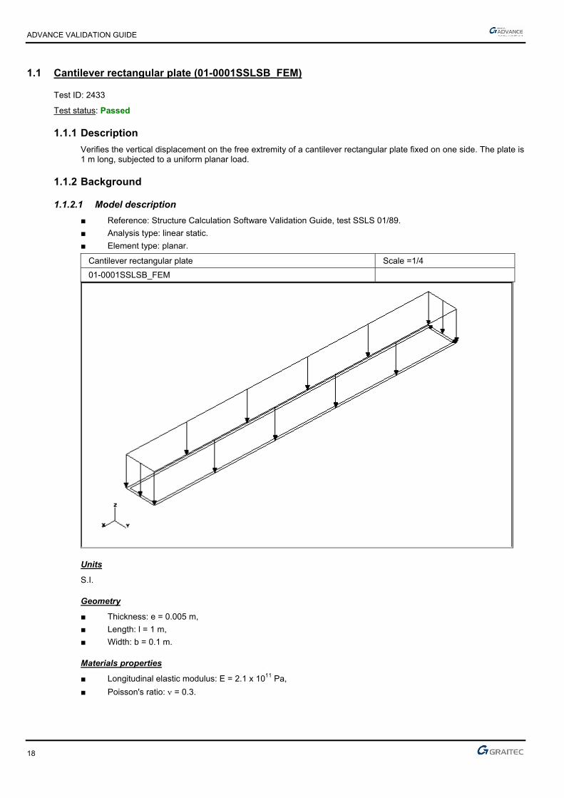
1.1 Cantilever rectangular plate (01-0001SSLSB_FEM)
Test ID: 2433
Test status: Passed
1.1.1 Description
Verifies the vertical displacement on the free extremity of a cantilever rectangular plate fixed on one side. The plate is 1 m long, subjected to a uniform planar load.
1.1.2 Background
1.1.2.1 Model description
■ Reference: Structure Calculation Software Validation Guide, test SSLS 01/89.
■ Analysis type: linear static.
■ Element type: planar.
Cantilever rectangular plate Scale =1/4
01-0001SSLSB_FEM
Units
S.I.
Geometry
■ Thickness: e = 0.005 m,
■ Length: l = 1 m,
■ Width: b = 0.1 m.
Materials properties
■ Longitudinal elastic modulus: E = 2.1 x 10¹¹ Pa,
■ Poisson's ratio: = 0.3.

ADVANCE VALIDATION GUIDE
19
Boundary conditions
■ Outer: Fixed at end x = 0,
■ Inner: None.
Loadings
■ External: Uniform load p = -1700 Pa on the upper surface,
■ Internal: None.
1.1.2.2 Displacement of the model in the linear elastic range
Reference solution
The reference displacement is calculated for the unsupported end located at x = 1m.
u = bl4p8EIz
= 0.1 x 14 x 1700
8 x 2.1 x 1011 x 0.1 x 0.0053
12 = -9.71 cm
Finite elements modeling
■ Planar element: plate, imposed mesh,
■ 1100 nodes,
■ 990 surface quadrangles.
Deformed shape
Deformed cantilever rectangular plate Scale =1/4
01-0001SSLSB_FEM

ADVANCE VALIDATION GUIDE
20
1.1.2.3 Theoretical results
Solver Result name Result description Reference value
CM2 DZ Vertical displacement on the free extremity [cm] -9.71
1.1.3 Calculated results
Result name Result description Value Error
DZ Vertical displacement on the free extremity [cm] -9.58696 cm 1.27%
ADVANCE VALIDATION GUIDE
21
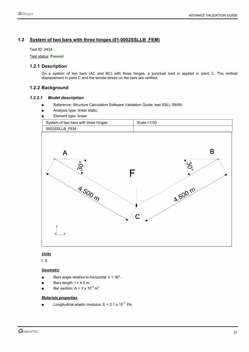
1.2 System of two bars with three hinges (01-0002SSLLB_FEM)
Test ID: 2434
Test status: Passed
1.2.1 Description
On a system of two bars (AC and BC) with three hinges, a punctual load in applied in point C. The vertical displacement in point C and the tensile stress on the bars are verified.
1.2.2 Background
1.2.2.1 Model description
■ Reference: Structure Calculation Software Validation Guide, test SSLL 09/89;
■ Analysis type: linear static;
■ Element type: linear.
System of two bars with three hinges Scale =1/33
0002SSLLB_FEM
4.500 m
30° 30°
4.500 m
AA BB
CC
FF
X
Y
Z X
Y
Z
Units
I. S.
Geometry
■ Bars angle relative to horizontal: = 30°,
■ Bars length: l = 4.5 m,
■ Bar section: A = 3 x 10⁻⁴ m2.
Materials properties
■ Longitudinal elastic modulus: E = 2.1 x 10¹¹ Pa.

ADVANCE VALIDATION GUIDE
22
Boundary conditions
■ Outer: Hinged in A and B,
■ Inner: Hinge on C
Loading
■ External: Punctual load in C: F = -21 x 103 N.
■ Internal: None.
1.2.2.2 Displacement of the model in C
Reference solution
uc = -3 x 10⁻³ m
Finite elements modeling
■ Linear element: beam, imposed mesh,
■ 21 nodes,
■ 20 linear elements.
Displacement shape
System of two bars with three hinges Scale =1/33
Displacement in C 0002SSLLB_FEM

ADVANCE VALIDATION GUIDE
23
1.2.2.3 Bars stresses
Reference solutions
AC bar = 70 MPa
BC bar = 70 MPa
Finite elements modeling
■ Linear element: beam, imposed mesh,
■ 21 nodes,
■ 20 linear elements.
1.2.2.4 Shape of the stress diagram
System of two bars with three hinges Scale =1/34
Bars stresses 0002SSLLB_FEM
1.2.2.5 Theoretical results
Solver Result name Result description Reference value
CM2 DZ Vertical displacement in point C [cm] -0.30
CM2 Sxx Tensile stress on AC bar [MPa] 70
CM2 Sxx Tensile stress on BC bar [MPa] 70
1.2.3 Calculated results
Result name Result description Value Error
DZ Vertical displacement in point C [cm] -0.299954 cm 0.02%
Sxx Tensile stress on AC bar [MPa] 69.9998 MPa 0.00%
Sxx Tensile stress on BC bar [MPa] 69.9998 MPa 0.00%
ADVANCE VALIDATION GUIDE
24
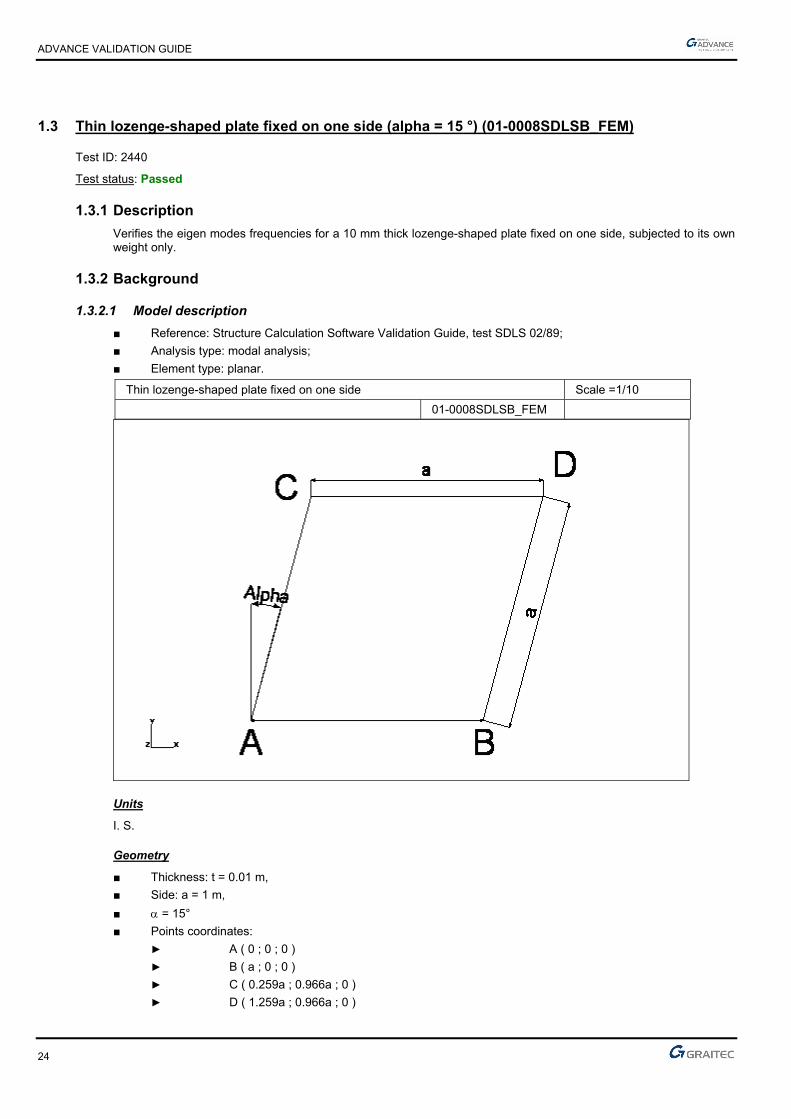
1.3 Thin lozenge-shaped plate fixed on one side (alpha = 15 °) (01-0008SDLSB_FEM)
Test ID: 2440
Test status: Passed
1.3.1 Description
Verifies the eigen modes frequencies for a 10 mm thick lozenge-shaped plate fixed on one side, subjected to its own weight only.
1.3.2 Background
1.3.2.1 Model description
■ Reference: Structure Calculation Software Validation Guide, test SDLS 02/89;
■ Analysis type: modal analysis;
■ Element type: planar.
Thin lozenge-shaped plate fixed on one side Scale =1/10
01-0008SDLSB_FEM
Units
I. S.
Geometry
■ Thickness: t = 0.01 m,
■ Side: a = 1 m,
■ = 15°
■ Points coordinates:
► A ( 0 ; 0 ; 0 )
► B ( a ; 0 ; 0 )
► C ( 0.259a ; 0.966a ; 0 )
► D ( 1.259a ; 0.966a ; 0 )
ADVANCE VALIDATION GUIDE
25
Materials properties
■ Longitudinal elastic modulus: E = 2.1 x 10¹¹ Pa,
■ Poisson's ratio: = 0.3,
■ Density: = 7800 kg/m3.
Boundary conditions
■ Outer: AB side fixed,
■ Inner: None.
Loading
■ External: None,
■ Internal: None.
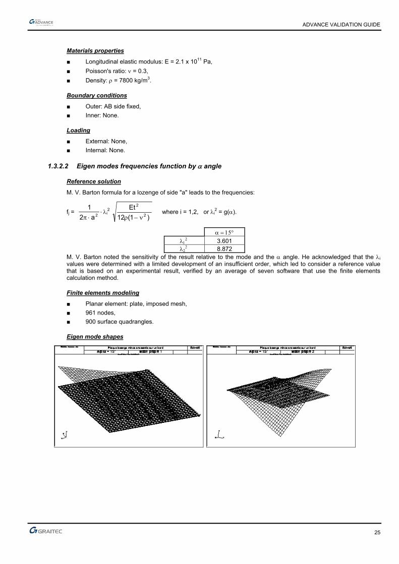
1.3.2.2 Eigen modes frequencies function by angle
Reference solution
M. V. Barton formula for a lozenge of side "a" leads to the frequencies:
fj = 2a2
1i
2 )1(12
Et2
2
where i = 1,2, or i
2 = g().
3.601
8.872 M. V. Barton noted the sensitivity of the result relative to the mode and the angle. He acknowledged that the i values were determined with a limited development of an insufficient order, which led to consider a reference value that is based on an experimental result, verified by an average of seven software that use the finite elements calculation method.
Finite elements modeling
■ Planar element: plate, imposed mesh,
■ 961 nodes,
■ 900 surface quadrangles.
Eigen mode shapes
ADVANCE VALIDATION GUIDE
26
1.3.2.3 Theoretical results
Solver Result name Result description Reference value
CM2 Eigen mode Eigen mode 1 frequency [Hz] 8.999
CM2 Eigen mode Eigen mode 2 frequency [Hz] 22.1714
1.3.3 Calculated results
Result name Result description Value Error
Eigen mode 1 frequency [Hz] 8.95 Hz -0.54%
Eigen mode 2 frequency [Hz] 21.69 Hz -2.17%

ADVANCE VALIDATION GUIDE
27
1.4 Thin circular ring fixed in two points (01-0006SDLLB_FEM)
Test ID: 2438
Test status: Passed
1.4.1 Description
Verifies the first eigen modes frequencies for a thin circular ring fixed in two points, subjected to its own weight only.
1.4.2 Background
1.4.2.1 Model description
■ Reference: Structure Calculation Software Validation Guide, test SDLL 12/89;
■ Analysis type: modal analysis, plane problem;
■ Element type: linear.
Thin circular ring fixed in two points Scale =1/2
01-0006SDLLB_FEM
Units
I. S.
Geometry
■ Average radius of curvature: OA = OB = R = 0.1 m,
■ Angular spacing between points A and B: 120° ;
■ Rectangular straight section:
► Thickness: h = 0.005 m,
► Width: b = 0.010 m,
► Section: A = 5 x 10⁻⁵ m2,
► Flexure moment of inertia relative to the vertical axis: I = 1.042 x 10⁻¹⁰ m4,
■ Point coordinates:
► O (0 ;0),
► A (-0.05 3 ; -0.05),
► B (0.05 3 ; -0.05).
ADVANCE VALIDATION GUIDE
28
Materials properties
■ Longitudinal elastic modulus: E = 7.2 x 10¹⁰ Pa
■ Poisson's ratio: = 0.3,
■ Density: = 2700 kg/m3.
Boundary conditions
■ Outer: Fixed at A and B,
■ Inner: None.
Loading
■ External: None,
■ Internal: None.
1.4.2.2 Eigen mode frequencies
Reference solutions
The deformation of the fixed ring is calculated from the deformations of the free-free thin ring
■ Symmetrical mode:
► u’i = i cos(i)
► v’i = sin (i)
► ’i = 1-i2
R sin (i)
■ Antisymmetrical mode:
► u’i = i sin(i)
► v’i = -cos (i)
► ’i = 1-i2
R cos (i)
From Green’s method results:
fj = 2
1j
2R
h
12
E
with a support angle of 120°.
i 1 2 3 4 Symmetrical mode 4.8497 14.7614 23.6157
Antisymmetrical mode 1.9832 9.3204 11.8490 21.5545
Finite elements modeling
■ Linear element: beam, without meshing,
■ 32 nodes,
■ 32 linear elements.

ADVANCE VALIDATION GUIDE
29
Eigen mode shapes
ADVANCE VALIDATION GUIDE
30
1.4.2.3 Theoretic results
Solver Result name Result description Reference value
CM2 Eigen mode Eigen mode 1 frequency - 1 antisymmetric 1 [Hz] 235.3
CM2 Eigen mode Eigen mode 2 frequency - 2 symmetric 1 [Hz] 575.3
CM2 Eigen mode Eigen mode 3 frequency - 3 antisymmetric 2 [Hz] 1105.7
CM2 Eigen mode Eigen mode 4 frequency - 4 antisymmetric 3 [Hz] 1405.6
CM2 Eigen mode Eigen mode 5 frequency - 5 symmetric 2 [Hz] 1751.1
CM2 Eigen mode Eigen mode 6 frequency - 6 antisymmetric 4 [Hz] 2557
CM2 Eigen mode Eigen mode 7 frequency - 7 symmetric 3 [Hz] 2801.5
1.4.3 Calculated results
Result name Result description Value Error
Eigen mode 1 frequency - 1 antisymmetric 1 [Hz] 236.32 Hz 0.43%
Eigen mode 2 frequency - 2 symmetric 1 [Hz] 578.52 Hz 0.56%
Eigen mode 3 frequency - 3 antisymmetric 2 [Hz] 1112.54 Hz 0.62%
Eigen mode 4 frequency - 4 antisymmetric 3 [Hz] 1414.22 Hz 0.61%
Eigen mode 5 frequency - 5 symmetric 2 [Hz] 1760 Hz 0.51%
Eigen mode 6 frequency - 6 antisymmetric 4 [Hz] 2569.97 Hz 0.51%
Eigen mode 7 frequency - 7 symmetric 3 [Hz] 2777.43 Hz -0.86%
ADVANCE VALIDATION GUIDE
31
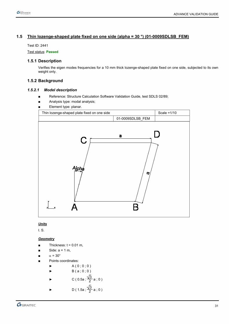
1.5 Thin lozenge-shaped plate fixed on one side (alpha = 30 °) (01-0009SDLSB_FEM)
Test ID: 2441
Test status: Passed
1.5.1 Description
Verifies the eigen modes frequencies for a 10 mm thick lozenge-shaped plate fixed on one side, subjected to its own weight only.
1.5.2 Background
1.5.2.1 Model description
■ Reference: Structure Calculation Software Validation Guide, test SDLS 02/89;
■ Analysis type: modal analysis;
■ Element type: planar.
Thin lozenge-shaped plate fixed on one side Scale =1/10
01-0009SDLSB_FEM
Units
I. S.
Geometry
■ Thickness: t = 0.01 m,
■ Side: a = 1 m,
■ = 30°
■ Points coordinates:
► A ( 0 ; 0 ; 0 )
► B ( a ; 0 ; 0 )
► C ( 0.5a ; 3 2 a ; 0 )
► D ( 1.5a ; 3 2 a ; 0 )
ADVANCE VALIDATION GUIDE
32
Materials properties
■ Longitudinal elastic modulus: E = 2.1 x 10¹¹ Pa,
■ Poisson's ratio: = 0.3,
■ Density: = 7800 kg/m3.
Boundary conditions
■ Outer: AB side fixed,
■ Inner: None.
Loading
■ External: None,
■ Internal: None.
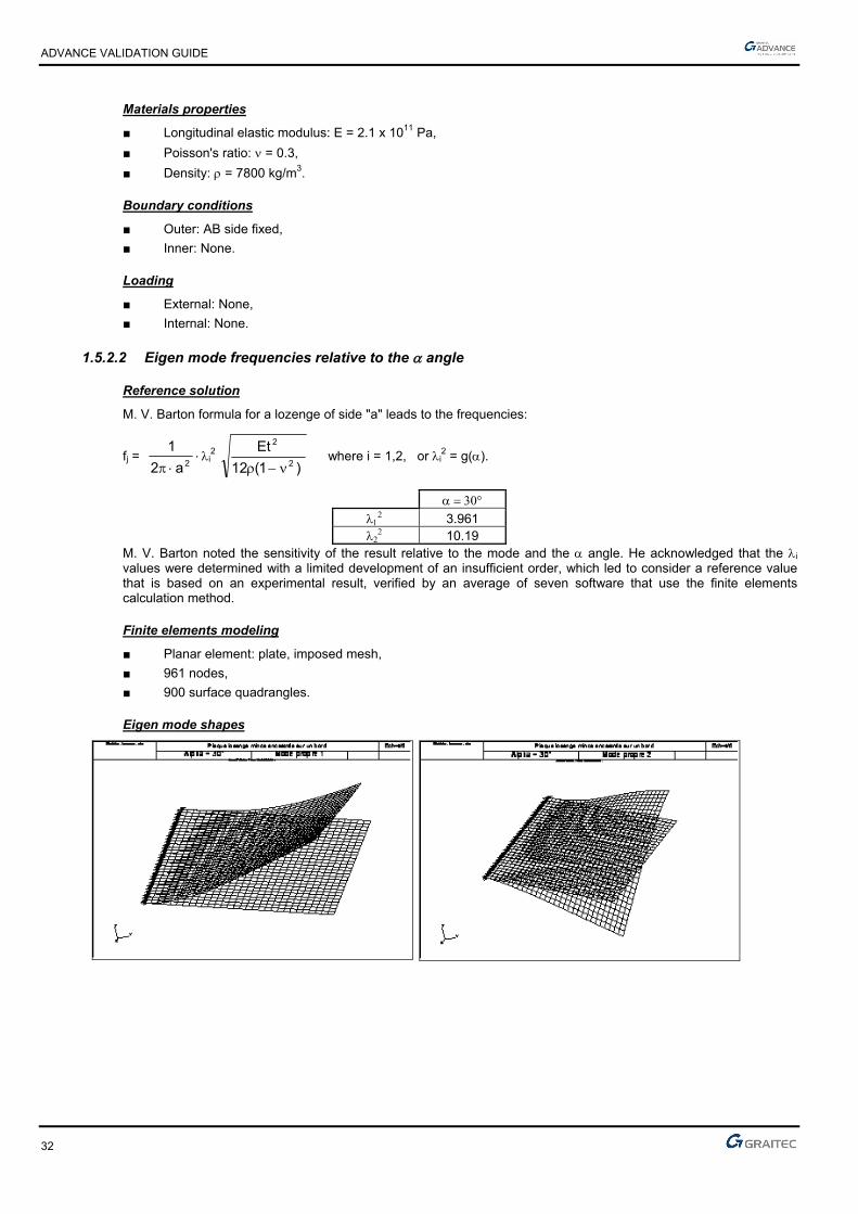
1.5.2.2 Eigen mode frequencies relative to the angle
Reference solution
M. V. Barton formula for a lozenge of side "a" leads to the frequencies:
fj = 2a2
1i
2 )1(12
Et2
2
where i = 1,2, or i
2 = g().
3.961
10.19 M. V. Barton noted the sensitivity of the result relative to the mode and the angle. He acknowledged that the i values were determined with a limited development of an insufficient order, which led to consider a reference value that is based on an experimental result, verified by an average of seven software that use the finite elements calculation method.
Finite elements modeling
■ Planar element: plate, imposed mesh,
■ 961 nodes,
■ 900 surface quadrangles.
Eigen mode shapes

ADVANCE VALIDATION GUIDE
33
1.5.2.3 Theoretical results
Solver Result name Result description Reference value
CM2 Eigen mode Eigen mode 1 frequency [Hz] 9.8987
CM2 Eigen mode Eigen mode 2 frequency [Hz] 25.4651
1.5.3 Calculated results
Result name Result description Value Error
Eigen mode 1 frequency [Hz] 9.82 Hz -0.80%
Eigen mode 2 frequency [Hz] 23.44 Hz -7.95%

ADVANCE VALIDATION GUIDE
34
1.6 Thin lozenge-shaped plate fixed on one side (alpha = 0 °) (01-0007SDLSB_FEM)
Test ID: 2439
Test status: Passed
1.6.1 Description
Verifies the eigen modes frequencies for a 10 mm thick lozenge-shaped plate fixed on one side, subjected to its own weight only.
1.6.2 Background
1.6.2.1 Model description
■ Reference: Structure Calculation Software Validation Guide, test SDLS 02/89;
■ Analysis type: modal analysis;
■ Element type: planar.
Thin lozenge-shaped plate fixed on one side Scale =1/10
01-0007SDLSB_FEM
Units
I. S.
Geometry
■ Thickness: t = 0.01 m,
■ Side: a = 1 m,
■ = 0°
■ Points coordinates:
► A ( 0 ; 0 ; 0 )
► B ( a ; 0 ; 0 )
► C ( 0 ; a ; 0 )
► D ( a ; a ; 0 )

ADVANCE VALIDATION GUIDE
35
Materials properties
■ Longitudinal elastic modulus: E = 2.1 x 10¹¹ Pa,
■ Poisson's ratio: = 0.3,
■ Density: = 7800 kg/m3.
Boundary conditions
■ Outer: AB side fixed,
■ Inner: None.
Loading
■ External: None,
■ Internal: None.
1.6.2.2 Eigen mode frequencies relative to the angle
Reference solution
M. V. Barton formula for a side "a" lozenge, leads to the frequencies:
fj = 2a2
1i
2 )1(12
Et2
2
where i = 1,2, and i
2 = g().
3.492
8.525 M.V. Barton noted the sensitivity of the result relative to the mode and the angle. He acknowledged that the i values were determined with a limited development of an insufficient order, which led to consider a reference value that is based on an experimental result, verified by an average of seven software that use the finite elements calculation method.
Finite elements modeling
■ Planar element: plate, imposed mesh,
■ 61 nodes,
■ 900 surface quadrangles.
Eigen mode shapes
ADVANCE VALIDATION GUIDE
36
1.6.2.3 Theoretical results
Solver Result name Result description Reference value
CM2 Eigen mode Eigen mode 1 frequency [Hz] 8.7266
CM2 Eigen mode Eigen mode 2 frequency [Hz] 21.3042
1.6.3 Calculated results
Result name Result description Value Error
Eigen mode 1 frequency [Hz] 8.67 Hz -0.65%
Eigen mode 2 frequency [Hz] 21.21 Hz -0.44%

ADVANCE VALIDATION GUIDE
37
1.7 Vibration mode of a thin piping elbow in plane (case 2) (01-0012SDLLB_FEM)
Test ID: 2444
Test status: Passed
1.7.1 Description
Verifies the vibration modes of a thin piping elbow (1 m radius) extended by two straight elements of length L, subjected to its self weight only.
1.7.2 Background
1.7.2.1 Model description
■ Reference: Structure Calculation Software Validation Guide, test SDLL 14/89;
■ Analysis type: modal analysis (plane problem);
■ Element type: linear.
Vibration mode of a thin piping elbow Scale = 1/11
Case 2 01-0012SDLLB_FEM
Units
I. S.
Geometry
■ Average radius of curvature: OA = R = 1 m,
■ L = 0.6 m,
■ Straight circular hollow section:
■ Outer diameter de = 0.020 m,
■ Inner diameter di = 0.016 m,
■ Section: A = 1.131 x 10⁻⁴ m2,
■ Flexure moment of inertia relative to the y-axis: Iy = 4.637 x 10⁻⁹ m4,
■ Flexure moment of inertia relative to z-axis: Iz = 4.637 x 10⁻⁹ m4,
■ Polar inertia: Ip = 9.274 x 10⁻⁹ m4.
ADVANCE VALIDATION GUIDE
38
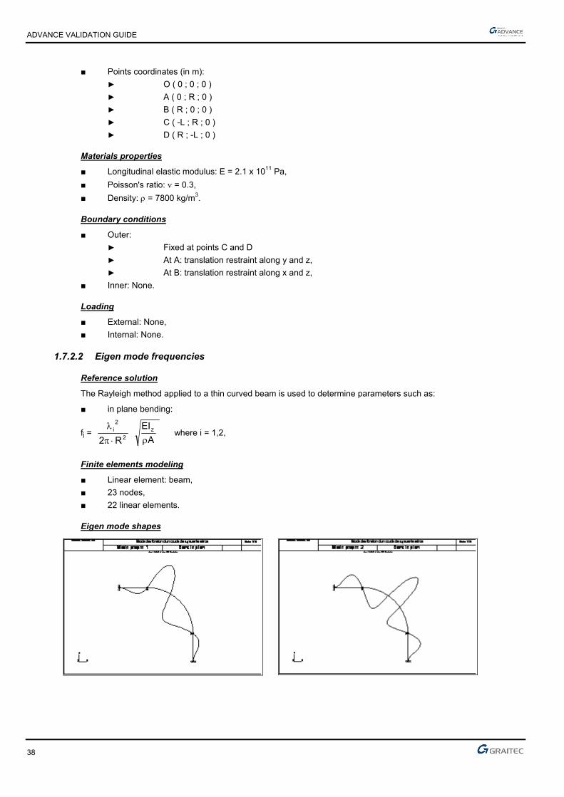
■ Points coordinates (in m):
► O ( 0 ; 0 ; 0 )
► A ( 0 ; R ; 0 )
► B ( R ; 0 ; 0 )
► C ( -L ; R ; 0 )
► D ( R ; -L ; 0 )
Materials properties
■ Longitudinal elastic modulus: E = 2.1 x 10¹¹ Pa,
■ Poisson's ratio: = 0.3,
■ Density: = 7800 kg/m3.
Boundary conditions
■ Outer:
► Fixed at points C and D
► At A: translation restraint along y and z,
► At B: translation restraint along x and z,
■ Inner: None.
Loading
■ External: None,
■ Internal: None.
1.7.2.2 Eigen mode frequencies
Reference solution
The Rayleigh method applied to a thin curved beam is used to determine parameters such as:
■ in plane bending:
fj = 2
2i
R2
A
EIz
where i = 1,2,
Finite elements modeling
■ Linear element: beam,
■ 23 nodes,
■ 22 linear elements.
Eigen mode shapes

ADVANCE VALIDATION GUIDE
39
1.7.2.3 Theoretical results
Solver Result name Result description Reference value
CM2 Eigen mode Eigen mode frequency in plane 1 [Hz] 94
CM2 Eigen mode Eigen mode frequency in plane 2 [Hz] 180
1.7.3 Calculated results
Result name Result description Value Error
Eigen mode frequency in plane 1 [Hz] 94.62 Hz 0.66%
Eigen mode frequency in plane 2 [Hz] 184.68 Hz 2.60%
ADVANCE VALIDATION GUIDE
40
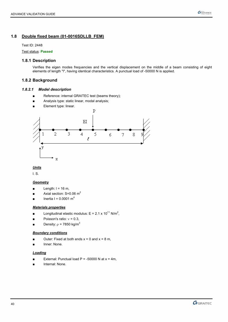
1.8 Double fixed beam (01-0016SDLLB_FEM)
Test ID: 2448
Test status: Passed
1.8.1 Description
Verifies the eigen modes frequencies and the vertical displacement on the middle of a beam consisting of eight elements of length "l", having identical characteristics. A punctual load of -50000 N is applied.
1.8.2 Background
1.8.2.1 Model description
■ Reference: internal GRAITEC test (beams theory);
■ Analysis type: static linear, modal analysis;
■ Element type: linear.
Units
I. S.
Geometry
■ Length: l = 16 m,
■ Axial section: S=0.06 m2
■ Inertia I = 0.0001 m4
Materials properties
■ Longitudinal elastic modulus: E = 2.1 x 10¹¹ N/m2,
■ Poisson's ratio: = 0.3,
■ Density: = 7850 kg/m3
Boundary conditions
■ Outer: Fixed at both ends x = 0 and x = 8 m,
■ Inner: None.
Loading
■ External: Punctual load P = -50000 N at x = 4m,
■ Internal: None.

ADVANCE VALIDATION GUIDE
41
1.8.2.2 Displacement of the model in the linear elastic range
Reference solution
The reference vertical displacement v5, is calculated at the middle of the beam at x = 2 m.
m 05079.00001.0111.2192
1650000
192
33
5
EEI
Plv
Finite elements modeling
■ Linear element: beam, imposed mesh,
■ 9 nodes,
■ 8 elements.
Deformed shape
Double fixed beam
Deformed
1.8.2.3 Eigen mode frequencies of the model in the linear elastic range
Reference solution
Knowing that the first four eigen mode frequencies of a double fixed beam are given by the following formula:
S
IE
Lf nn .
.
..2 2
2
where for the first 4 eigen modes frequencies
Hz 26.228=f 8.199
Hz 15.871=f 9.120
Hz 8.095=f 67.61
Hz 2.937=f 37.22
424
323
222
121
Finite elements modeling
■ Linear element: beam, imposed mesh,
■ 9 nodes,
■ 8 elements.

ADVANCE VALIDATION GUIDE
42
Modal deformations
Double fixed beam
Mode 1
Double fixed beam
Mode 2
Double fixed beam
Mode 3
Double fixed beam
Mode 4
ADVANCE VALIDATION GUIDE
43
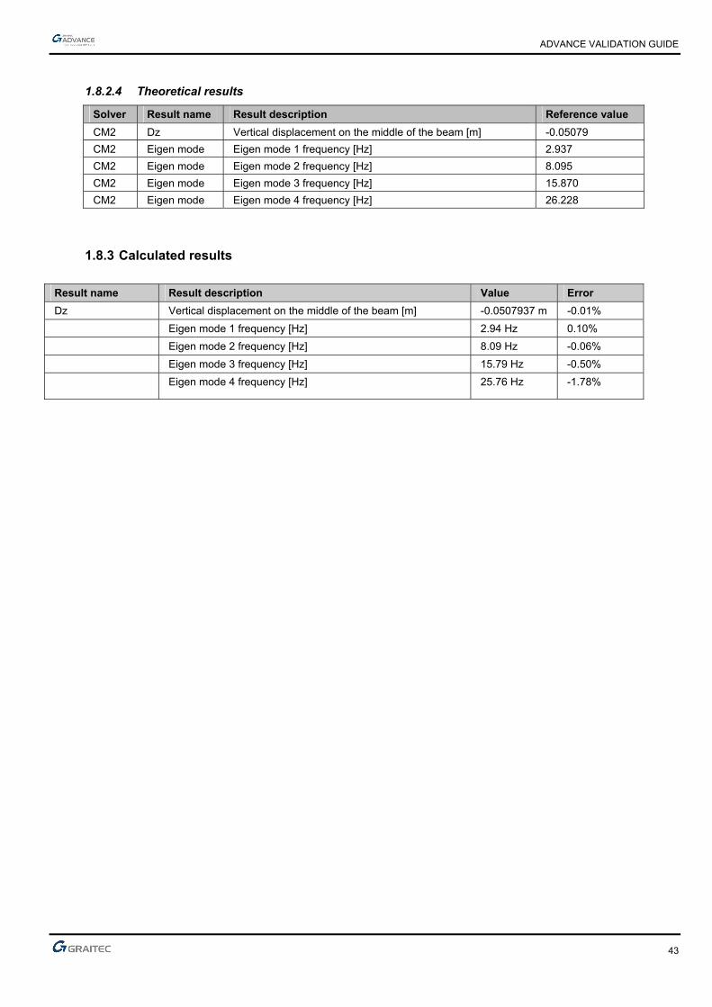
1.8.2.4 Theoretical results
Solver Result name Result description Reference value
CM2 Dz Vertical displacement on the middle of the beam [m] -0.05079
CM2 Eigen mode Eigen mode 1 frequency [Hz] 2.937
CM2 Eigen mode Eigen mode 2 frequency [Hz] 8.095
CM2 Eigen mode Eigen mode 3 frequency [Hz] 15.870
CM2 Eigen mode Eigen mode 4 frequency [Hz] 26.228
1.8.3 Calculated results
Result name Result description Value Error
Dz Vertical displacement on the middle of the beam [m] -0.0507937 m -0.01%
Eigen mode 1 frequency [Hz] 2.94 Hz 0.10%
Eigen mode 2 frequency [Hz] 8.09 Hz -0.06%
Eigen mode 3 frequency [Hz] 15.79 Hz -0.50%
Eigen mode 4 frequency [Hz] 25.76 Hz -1.78%

ADVANCE VALIDATION GUIDE
44
1.9 Vibration mode of a thin piping elbow in plane (case 3) (01-0013SDLLB_FEM)
Test ID: 2445
Test status: Passed
1.9.1 Description
Verifies the vibration modes of a thin piping elbow (1 m radius) extended by two straight elements of length L, subjected to its self weight only.
1.9.2 Background
1.9.2.1 Model description
■ Reference: Structure Calculation Software Validation Guide, test SDLL 14/89;
■ Analysis type: modal analysis (plane problem);
■ Element type: linear.
Vibration mode of a thin piping elbow Scale = 1/12
Case 3 01-0013SDLLB_FEM
Units
I. S.

ADVANCE VALIDATION GUIDE
45
Geometry
■ Average radius of curvature: OA = R = 1 m,
■ Straight circular hollow section:
■ Outer diameter: de = 0.020 m,
■ Inner diameter: di = 0.016 m,
■ Section: A = 1.131 x 10⁻⁴ m2,
■ Flexure moment of inertia relative to the y-axis: Iy = 4.637 x 10⁻⁹ m4,
■ Flexure moment of inertia relative to z-axis: Iz = 4.637 x 10⁻⁹ m4,
■ Polar inertia: Ip = 9.274 x 10⁻⁹ m4.
■ Points coordinates (in m):
► O ( 0 ; 0 ; 0 )
► A ( 0 ; R ; 0 )
► B ( R ; 0 ; 0 )
► C ( -L ; R ; 0 )
► D ( R ; -L ; 0 )
Materials properties
■ Longitudinal elastic modulus: E = 2.1 x 10¹¹ Pa,
■ Poisson's ratio: = 0.3,
■ Density: = 7800 kg/m3.
Boundary conditions
■ Outer:
► Fixed at points C and Ds,
► At A: translation restraint along y and z,
► At B: translation restraint along x and z,
■ Inner: None.
Loading
■ External: None,
■ Internal: None.
1.9.2.2 Eigen mode frequencies
Reference solution
The Rayleigh method applied to a thin curved beam is used to determine parameters such as:
■ in plane bending:
fj = 2
2i
R2
A
EIz
where i = 1,2,
Finite elements modeling
■ Linear element: beam,
■ 41 nodes,
■ 40 linear elements.

ADVANCE VALIDATION GUIDE
46
Eigen mode shapes
1.9.2.3 Theoretical results
Solver Result name Result description Reference value
CM2 Eigen mode Eigen mode frequency in plane 1 [Hz] 25.300
CM2 Eigen mode Eigen mode frequency in plane 2 [Hz] 27.000
1.9.3 Calculated results
Result name Result description Value Error
Eigen mode frequency in plane 1 [Hz] 24.96 Hz -1.34%
Eigen mode frequency in plane 2 [Hz] 26.71 Hz -1.07%

ADVANCE VALIDATION GUIDE
47
1.10 Short beam on simple supports (on the neutral axis) (01-0017SDLLB_FEM)
Test ID: 2449
Test status: Passed
1.10.1 Description
Verifies the first eigen mode frequencies of a short beam on simple supports (the supports are located on the neutral axis), subjected to its own weight only.
1.10.2 Background
■ Reference: Structure Calculation Software Validation Guide, test SDLL 01/89;
■ Analysis type: modal analysis (plane problem);
■ Element type: linear.
Short beam on simple supports on the neutral axis Scale = 1/6
01-0017SDLLB_FEM
Units
I. S.
Geometry
■ Height: h = 0.2 m,
■ Length: l = 1 m,
■ Width: b = 0.1 m,
■ Section: A = 2 x 10⁻² m4,
■ Flexure moment of inertia relative to z-axis: Iz = 6.667 x 10⁻⁵ m4.
Materials properties
■ Longitudinal elastic modulus: E = 2.1 x 10¹¹ Pa,
■ Poisson's ratio: = 0.3,
■ Density: = 7800 kg/m3.

ADVANCE VALIDATION GUIDE
48
Boundary conditions
■ Outer:
► Hinged at A (null horizontal and vertical displacements),
► Simple support in B.
■ Inner: None.
Loading
■ External: None.
■ Internal: None.
1.10.2.1 Eigen modes frequencies
Reference solution
The bending beams equation gives, when superimposing, the effects of simple bending, shear force deformations and rotation inertia, Timoshenko formula.
The reference eigen modes frequencies are determined by a numerical simulation of this equation, independent of any software.
The eigen frequencies in tension-compression are given by:
fi =
l2i
E
where i = 2
)1i2(
Finite elements modeling
■ Linear element: S beam, imposed mesh,
■ 10 nodes,
■ 9 linear elements.
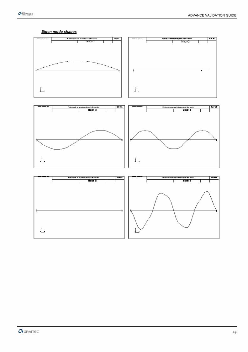
ADVANCE VALIDATION GUIDE
49
Eigen mode shapes
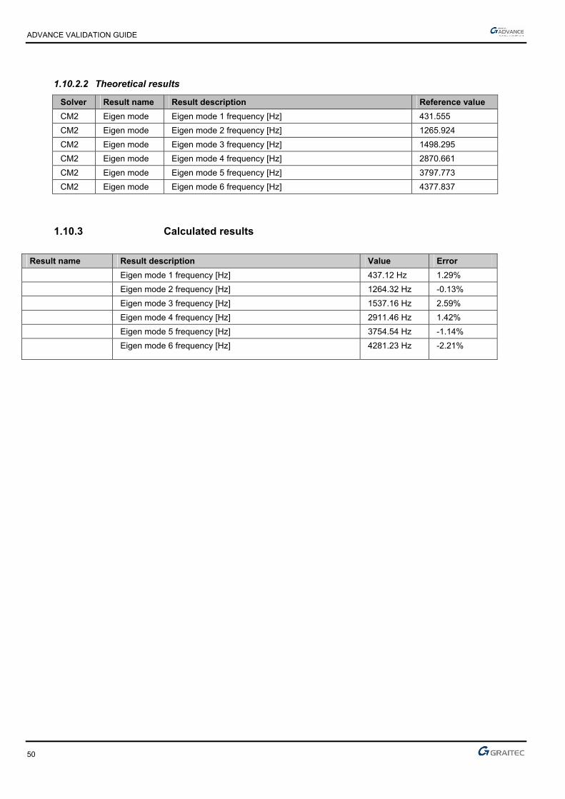
ADVANCE VALIDATION GUIDE
50
1.10.2.2 Theoretical results
Solver Result name Result description Reference value
CM2 Eigen mode Eigen mode 1 frequency [Hz] 431.555
CM2 Eigen mode Eigen mode 2 frequency [Hz] 1265.924
CM2 Eigen mode Eigen mode 3 frequency [Hz] 1498.295
CM2 Eigen mode Eigen mode 4 frequency [Hz] 2870.661
CM2 Eigen mode Eigen mode 5 frequency [Hz] 3797.773
CM2 Eigen mode Eigen mode 6 frequency [Hz] 4377.837
1.10.3 Calculated results
Result name Result description Value Error
Eigen mode 1 frequency [Hz] 437.12 Hz 1.29%
Eigen mode 2 frequency [Hz] 1264.32 Hz -0.13%
Eigen mode 3 frequency [Hz] 1537.16 Hz 2.59%
Eigen mode 4 frequency [Hz] 2911.46 Hz 1.42%
Eigen mode 5 frequency [Hz] 3754.54 Hz -1.14%
Eigen mode 6 frequency [Hz] 4281.23 Hz -2.21%

ADVANCE VALIDATION GUIDE
51
1.11 Rectangular thin plate simply supported on its perimeter (01-0020SDLSB_FEM)
Test ID: 2452
Test status: Passed
1.11.1 Description
Verifies the first eigen mode frequencies of a thin rectangular plate simply supported on its perimeter.
1.11.2 Background
1.11.2.1 Model description
■ Reference: Structure Calculation Software Validation Guide, test SDLS 03/89;
■ Analysis type: modal analysis;
■ Element type: planar.
Rectangular thin plate simply supported on its perimeter Scale = 1/8
01-0020SDLSB_FEM
Units
I. S.
Geometry
■ Length: a = 1.5 m,
■ Width: b = 1 m,
■ Thickness: t = 0.01 m,
■ Points coordinates in m:
► A (0 ;0 ;0)
► B (0 ;1.5 ;0)
► C (1 ;1.5 ;0)
► D (1 ;0 ;0)

ADVANCE VALIDATION GUIDE
52
Materials properties
■ Longitudinal elastic modulus: E = 2.1 x 10¹¹ Pa,
■ Poisson's ratio: = 0.3,
■ Density: = 7800 kg/m3.
Boundary conditions
■ Outer:
► Simple support on all sides,
► For the modeling: hinged at A, B and D.
■ Inner: None.
Loading
■ External: None.
■ Internal: None.
1.11.2.2 Eigen modes frequencies
Reference solution
M. V. Barton formula for a rectangular plate with supports on all four sides, leads to:
fij = 2
[ (
a
i)2 + (
b
j)2]
)1(12
Et2
2
where:
i = number of half-length of wave along y ( dimension a)
j = number of half-length of wave along x ( dimension b)
Finite elements modeling
■ Planar element: shell,
■ 496 nodes,
■ 450 planar elements.

ADVANCE VALIDATION GUIDE
53
Eigen mode shapes

ADVANCE VALIDATION GUIDE
54
1.11.2.3 Theoretical results
Solver Result name Result description Reference value
CM2 Eigen mode Eigen mode “i" - “j” frequency, for i = 1; j = 1. [Hz] 35.63
CM2 Eigen mode Eigen mode “i" - “j” frequency, for i = 2; j = 1. [Hz] 68.51
CM2 Eigen mode Eigen mode “i" - “j” frequency, for i = 1; j = 2. [Hz] 109.62
CM2 Eigen mode Eigen mode “i" - “j” frequency, for i = 3; j = 1. [Hz] 123.32
CM2 Eigen mode Eigen mode “i" - “j” frequency, for i = 2; j = 2. [Hz] 142.51
CM2 Eigen mode Eigen mode “i" - “j” frequency, for i = 3; j = 2. [Hz] 197.32
1.11.3 Calculated results
Result name Result description Value Error
Eigen mode "i" - "j" frequency, for i = 1; j = 1 (Mode 1) [Hz] 35.58 Hz -0.14%
Eigen mode "i" - "j" frequency, for i = 2; j = 1 (Mode 2) [Hz] 68.29 Hz -0.32%
Eigen mode "i" - "j" frequency, for i = 1; j = 2 (Mode 3) [Hz] 109.98 Hz 0.33%
Eigen mode "i" - "j" frequency, for i = 3; j = 1 (Mode 4) [Hz] 123.02 Hz -0.24%
Eigen mode "i" - "j" frequency, for i = 2; j = 2 (Mode 5) [Hz] 141.98 Hz -0.37%
Eigen mode "i" - "j" frequency, for i = 3; j = 2 (Mode 6) [Hz] 195.55 Hz -0.90%
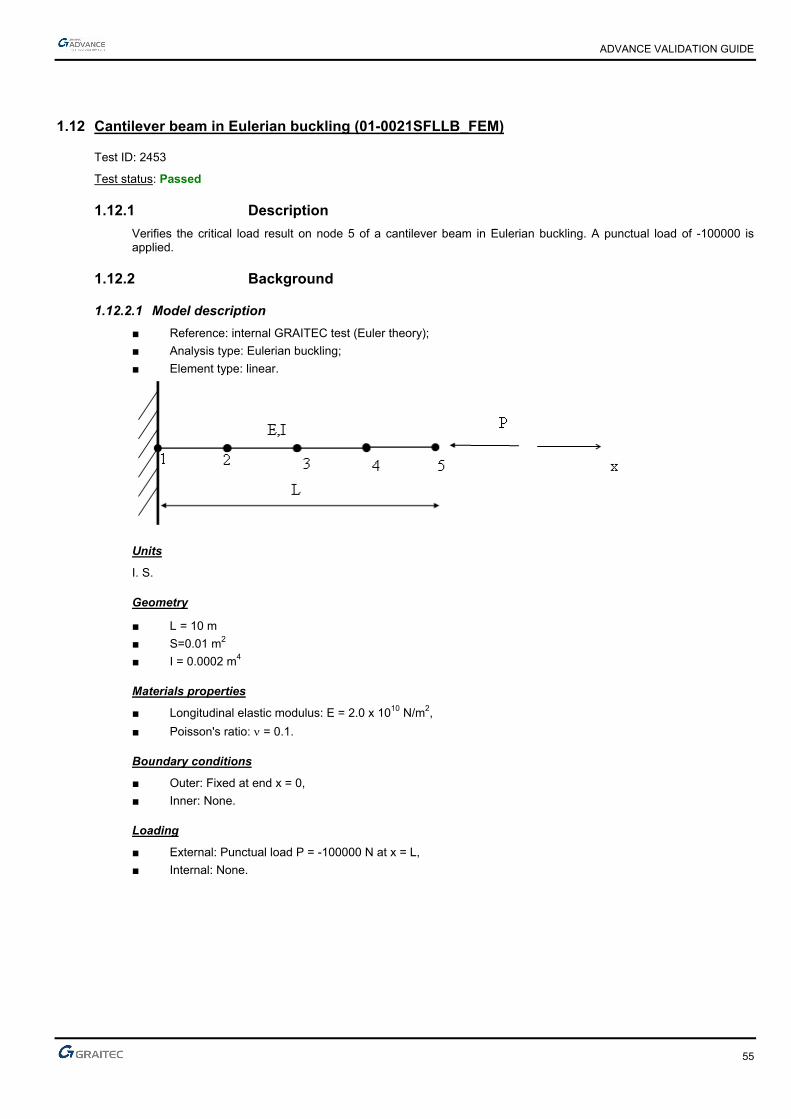
ADVANCE VALIDATION GUIDE
55
1.12 Cantilever beam in Eulerian buckling (01-0021SFLLB_FEM)
Test ID: 2453
Test status: Passed
1.12.1 Description
Verifies the critical load result on node 5 of a cantilever beam in Eulerian buckling. A punctual load of -100000 is applied.
1.12.2 Background
1.12.2.1 Model description
■ Reference: internal GRAITEC test (Euler theory);
■ Analysis type: Eulerian buckling;
■ Element type: linear.
Units
I. S.
Geometry
■ L= 10 m
■ S=0.01 m2
■ I = 0.0002 m4
Materials properties
■ Longitudinal elastic modulus: E = 2.0 x 10¹⁰ N/m2,
■ Poisson's ratio: = 0.1.
Boundary conditions
■ Outer: Fixed at end x = 0,
■ Inner: None.
Loading
■ External: Punctual load P = -100000 N at x = L,
■ Internal: None.
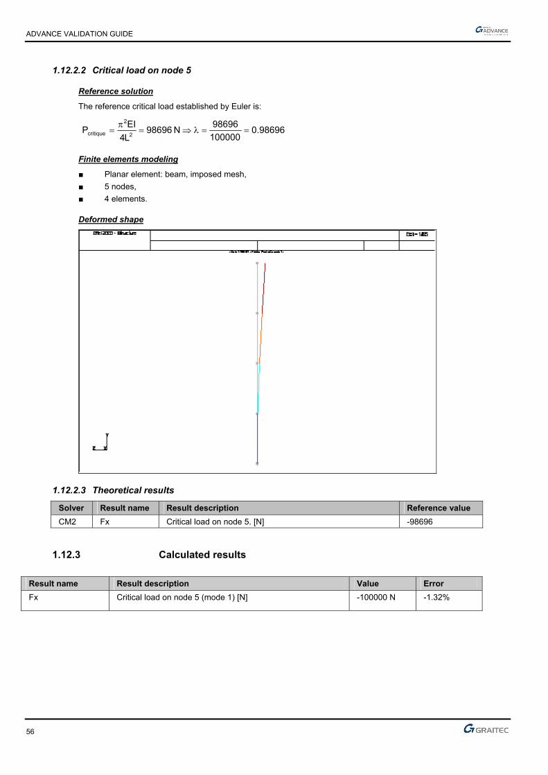
ADVANCE VALIDATION GUIDE
56
1.12.2.2 Critical load on node 5
Reference solution
The reference critical load established by Euler is:
98696.0100000
98696N 98696
L4
EIP
2
2
critique
Finite elements modeling
■ Planar element: beam, imposed mesh,
■ 5 nodes,
■ 4 elements.
Deformed shape
1.12.2.3 Theoretical results
Solver Result name Result description Reference value
CM2 Fx Critical load on node 5. [N] -98696
1.12.3 Calculated results
Result name Result description Value Error
Fx Critical load on node 5 (mode 1) [N] -100000 N -1.32%

ADVANCE VALIDATION GUIDE
57
1.13 Vibration mode of a thin piping elbow in plane (case 1) (01-0011SDLLB_FEM)
Test ID: 2443
Test status: Passed
1.13.1 Description
Verifies the vibration modes of a thin piping elbow (1 m radius) with fixed ends and subjected to its self weight only.
1.13.2 Background
1.13.2.1 Model description
■ Reference: Structure Calculation Software Validation Guide, test SDLL 14/89;
■ Analysis type: modal analysis (plane problem);
■ Element type: linear.
Vibration mode of a thin piping elbow in plane Scale = 1/7
Case 1 01-0011SDLLB_FEM
Units
I. S.
Geometry
■ Average radius of curvature: OA = R = 1 m,
■ Straight circular hollow section:
■ Outer diameter: de = 0.020 m,
■ Inner diameter: di = 0.016 m,
■ Section: A = 1.131 x 10⁻⁴ m2,
■ Flexure moment of inertia relative to the y-axis: Iy = 4.637 x 10⁻⁹ m4,
■ Flexure moment of inertia relative to z-axis: Iz = 4.637 x 10⁻⁹ m4,
■ Polar inertia: Ip = 9.274 x 10⁻⁹ m4.
■ Points coordinates (in m):
► O ( 0 ; 0 ; 0 )
► A ( 0 ; R ; 0 )
► B ( R ; 0 ; 0 )
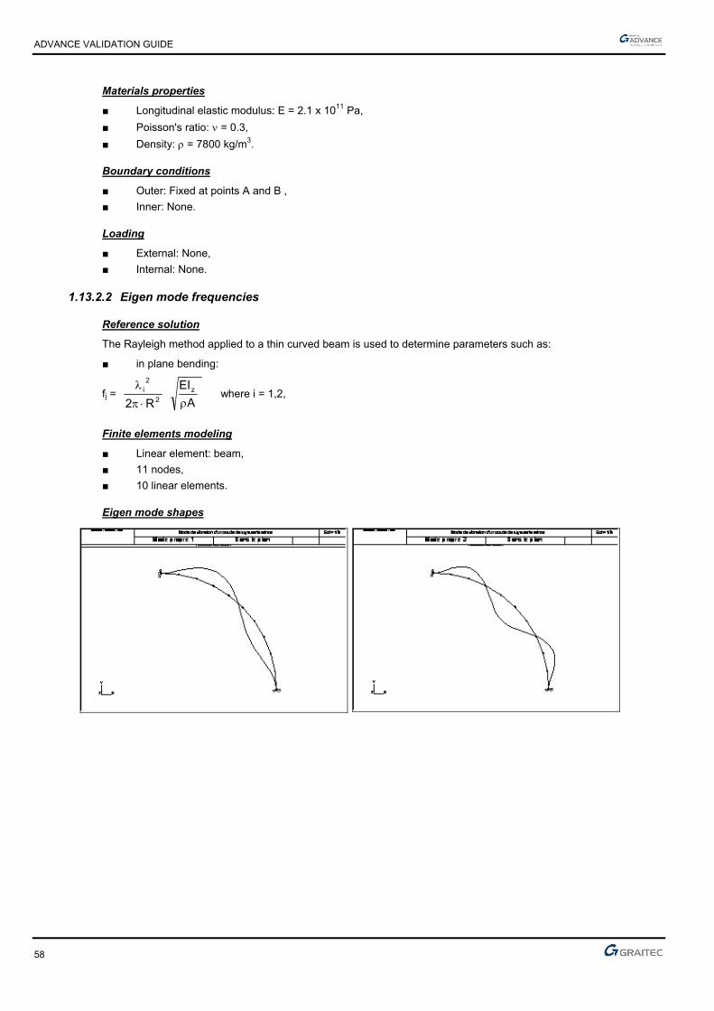
ADVANCE VALIDATION GUIDE
58
Materials properties
■ Longitudinal elastic modulus: E = 2.1 x 10¹¹ Pa,
■ Poisson's ratio: = 0.3,
■ Density: = 7800 kg/m3.
Boundary conditions
■ Outer: Fixed at points A and B ,
■ Inner: None.
Loading
■ External: None,
■ Internal: None.
1.13.2.2 Eigen mode frequencies
Reference solution
The Rayleigh method applied to a thin curved beam is used to determine parameters such as:
■ in plane bending:
fj = 2
2i
R2
A
EIz
where i = 1,2,
Finite elements modeling
■ Linear element: beam,
■ 11 nodes,
■ 10 linear elements.
Eigen mode shapes

ADVANCE VALIDATION GUIDE
59
1.13.2.3 Theoretical results
Solver Result name Result description Reference value
CM2 Eigen mode Eigen mode frequency in plane 1 [Hz] 119
CM2 Eigen mode Eigen mode frequency in plane 2 [Hz] 227
1.13.3 Calculated results
Result name Result description Value Error
Eigen mode frequency in plane 1 [Hz] 120.09 Hz 0.92%
Eigen mode frequency in plane 2 [Hz] 227.1 Hz 0.04%
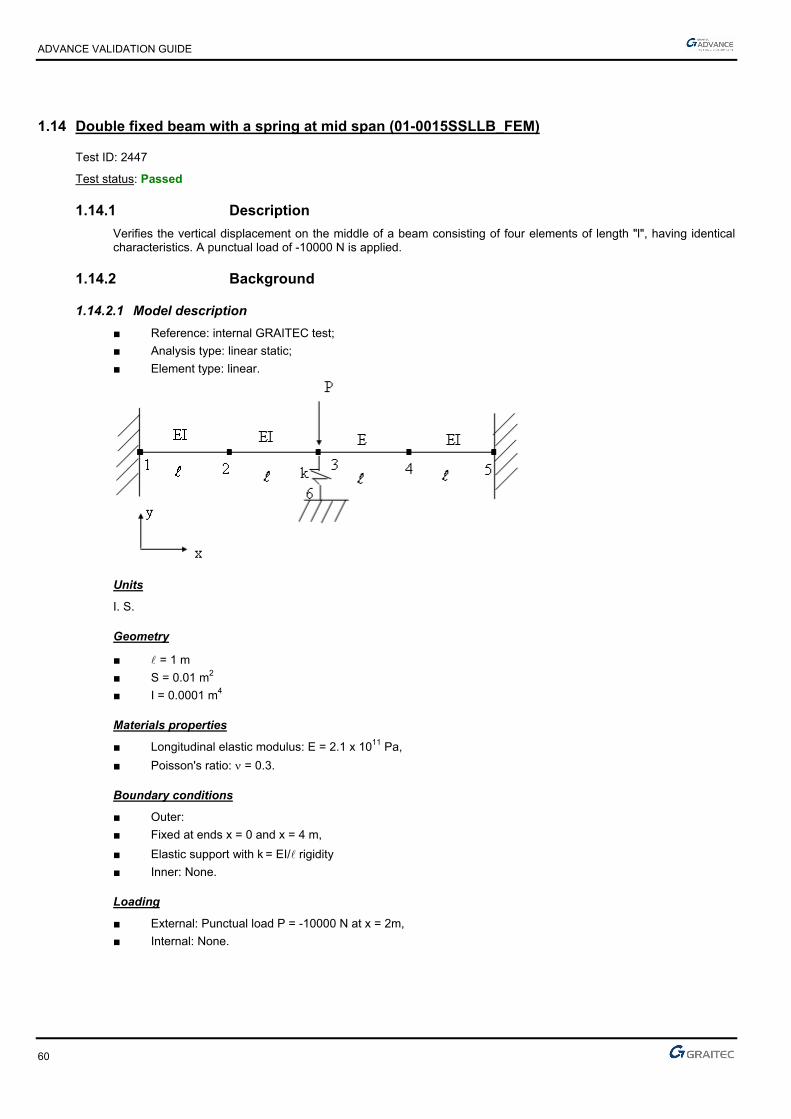
ADVANCE VALIDATION GUIDE
60
1.14 Double fixed beam with a spring at mid span (01-0015SSLLB_FEM)
Test ID: 2447
Test status: Passed
1.14.1 Description
Verifies the vertical displacement on the middle of a beam consisting of four elements of length "l", having identical characteristics. A punctual load of -10000 N is applied.
1.14.2 Background
1.14.2.1 Model description
■ Reference: internal GRAITEC test;
■ Analysis type: linear static;
■ Element type: linear.
Units
I. S.
Geometry
■ = 1 m
■ S = 0.01 m2
■ I = 0.0001 m4
Materials properties
■ Longitudinal elastic modulus: E = 2.1 x 10¹¹ Pa,
■ Poisson's ratio: = 0.3.
Boundary conditions
■ Outer:
■ Fixed at ends x = 0 and x = 4 m,
■ Elastic support with k = EI/ rigidity
■ Inner: None.
Loading
■ External: Punctual load P = -10000 N at x = 2m,
■ Internal: None.
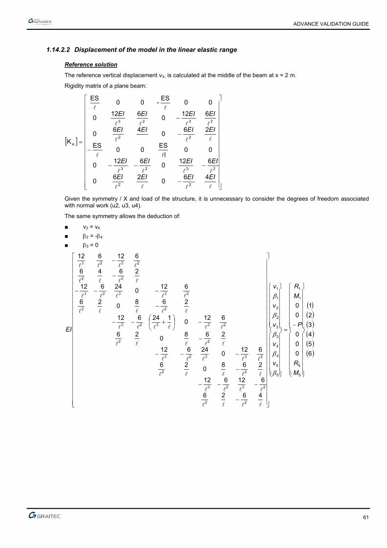
ADVANCE VALIDATION GUIDE
61
1.14.2.2 Displacement of the model in the linear elastic range
Reference solution
The reference vertical displacement v3, is calculated at the middle of the beam at x = 2 m.
Rigidity matrix of a plane beam:
EIEIEIEI
EIEIEIEI
EIEIEIEI
EIEIEIEI
460
260
6120
6120
00l
ES00
ES
260
460
6120
6120
00ES
-00ES
K
22
2323
22
2323
e
Given the symmetry / X and load of the structure, it is unnecessary to consider the degrees of freedom associated with normal work (u2, u3, u4).
The same symmetry allows the deduction of:
■ v2 = v4
■ 2 = -4
■ 3 = 0
6
5
4
3
2
1
0
0
0
0
0
4626
612612
2680
26
6120
24612
2680
26
6120
124612
2680
26
6120
24612
2646
612612
5
5
1
1
5
5
4
4
3
3
2
2
1
1
22
22
22
22
22
22
22
22
22
22
M
R
P
M
R
v
v
v
v
v
EI
33
333
333
333
33

ADVANCE VALIDATION GUIDE
62
The elementary rigidity matrix of the spring in its local axis system, )(
)(
11
11
6
35 U
UEIk
, must be expressed in
the global axis system by means of the rotation matrix (90° rotation):
6
6
6
3
3
3
5
000000
010010
000000
000000
010010
000000
v
u
v
u
EIK
344332 4
3 0
826vv
344332332 0
24612vvvv
y)unnecessar(usually 026826
244423222vvvv
(3) m 10 11905.03
612124612 03
2
3
34243332223
EIl
Pv
EI
Pvvv
Finite elements modeling
■ Linear element: beam, imposed mesh,
■ 6 nodes,
■ 4 linear elements + 1 spring,
Deformed shape
Double fixed beam with a spring at mid span
Deformed
Note: the displacement is expressed here in m
1.14.2.3 Theoretical results
Solver Result name Result description Reference value
CM2 Dz Vertical displacement on the middle of the beam [mm] -0.11905
1.14.3 Calculated results
Result name Result description Value Error
Dz Vertical displacement on the middle of the beam [mm] -0.119048 mm 0.00%

ADVANCE VALIDATION GUIDE
63
1.15 Thin square plate fixed on one side (01-0019SDLSB_FEM)
Test ID: 2451
Test status: Passed
1.15.1 Description
Verifies the first eigen modes frequencies of a thin square plate fixed on one side.
1.15.2 Background
1.15.2.1 Model description
■ Reference: Structure Calculation Software Validation Guide, test SDLS 01/89;
■ Analysis type: modal analysis;
■ Element type: planar.
Thin square plate fixed on one side Scale = 1/6
01-0019SDLSB_FEM
Units
I. S.
Geometry
■ Side: a = 1 m,
■ Thickness: t = 1 m,
■ Points coordinates in m:
► A (0 ;0 ;0)
► B (1 ;0 ;0)
► C (1 ;1 ;0)
► D (0 ;1 ;0)
ADVANCE VALIDATION GUIDE
64
Materials properties
■ Longitudinal elastic modulus: E = 2.1 x 10¹¹ Pa,
■ Poisson's ratio: = 0.3,
■ Density: = 7800 kg/m3.
Boundary conditions
■ Outer: Edge AD fixed.
■ Inner: None.
Loading
■ External: None.
■ Internal: None.
1.15.2.2 Eigen modes frequencies
Reference solution
M. V. Barton formula for a square plate with side "a", leads to:
fj = 2a2
1
i
2 )1(12
Et2
2
where i = 1,2, . . .
i 1 2 3 4 5 6 i 3.492 8.525 21.43 27.33 31.11 54.44
Finite elements modeling
■ Planar element: shell,
■ 959 nodes,
■ 900 planar elements.

ADVANCE VALIDATION GUIDE
65
Eigen mode shapes
Thin square plate fixed on one side
Mode 1
Thin square plate fixed on one side
Mode 2
Thin square plate fixed on one side
Mode 3
ADVANCE VALIDATION GUIDE
66
1.15.2.3 Theoretical results
Solver Result name Result description Reference value
CM2 Eigen mode Eigen mode 1 frequency [Hz] 8.7266
CM2 Eigen mode Eigen mode 2 frequency [Hz] 21.3042
CM2 Eigen mode Eigen mode 3 frequency [Hz] 53.5542
CM2 Eigen mode Eigen mode 4 frequency [Hz] 68.2984
CM2 Eigen mode Eigen mode 5 frequency [Hz] 77.7448
CM2 Eigen mode Eigen mode 6 frequency [Hz] 136.0471
1.15.3 Calculated results
Result name Result description Value Error
Eigen mode 1 frequency [Hz] 8.67 Hz -0.65%
Eigen mode 2 frequency [Hz] 21.22 Hz -0.40%
Eigen mode 3 frequency [Hz] 53.13 Hz -0.79%
Eigen mode 4 frequency [Hz] 67.74 Hz -0.82%
Eigen mode 5 frequency [Hz] 77.15 Hz -0.77%
Eigen mode 6 frequency [Hz] 134.65 Hz -1.03%
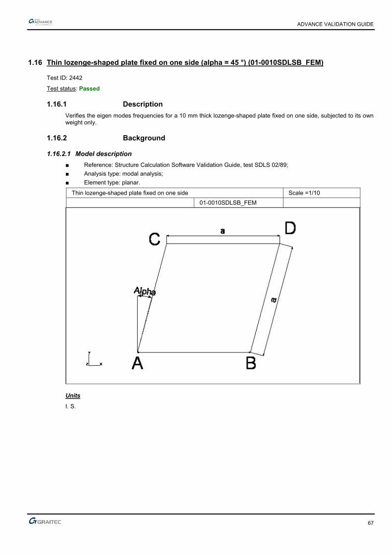
ADVANCE VALIDATION GUIDE
67
1.16 Thin lozenge-shaped plate fixed on one side (alpha = 45 °) (01-0010SDLSB_FEM)
Test ID: 2442
Test status: Passed
1.16.1 Description
Verifies the eigen modes frequencies for a 10 mm thick lozenge-shaped plate fixed on one side, subjected to its own weight only.
1.16.2 Background
1.16.2.1 Model description
■ Reference: Structure Calculation Software Validation Guide, test SDLS 02/89;
■ Analysis type: modal analysis;
■ Element type: planar.
Thin lozenge-shaped plate fixed on one side Scale =1/10
01-0010SDLSB_FEM
Units
I. S.
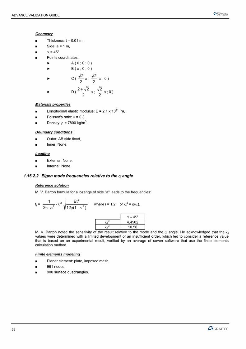
ADVANCE VALIDATION GUIDE
68
Geometry
■ Thickness: t = 0.01 m,
■ Side: a = 1 m,
■ = 45°
■ Points coordinates:
► A ( 0 ; 0 ; 0 )
► B ( a ; 0 ; 0 )
► C ( 2
2a ;
2
2 a ; 0 )
► D (2
22 a ;
2
2a ; 0 )
Materials properties
■ Longitudinal elastic modulus: E = 2.1 x 10¹¹ Pa,
■ Poisson's ratio: = 0.3,
■ Density: = 7800 kg/m3.
Boundary conditions
■ Outer: AB side fixed,
■ Inner: None.
Loading
■ External: None,
■ Internal: None.
1.16.2.2 Eigen mode frequencies relative to the angle
Reference solution
M. V. Barton formula for a lozenge of side "a" leads to the frequencies:
fj = 2a2
1i
2 )1(12
Et2
2
where i = 1,2, or i
2 = g().
4.4502
10.56 M. V. Barton noted the sensitivity of the result relative to the mode and the angle. He acknowledged that the i values were determined with a limited development of an insufficient order, which led to consider a reference value that is based on an experimental result, verified by an average of seven software that use the finite elements calculation method.
Finite elements modeling
■ Planar element: plate, imposed mesh,
■ 961 nodes,
■ 900 surface quadrangles.

ADVANCE VALIDATION GUIDE
69
Eigen mode shapes
1.16.2.3 Theoretical results
Solver Result name Result description Reference value
CM2 Eigen mode Eigen mode 1 frequency [Hz] 11.1212
CM2 Eigen mode Eigen mode 2 frequency [Hz] 26.3897
1.16.3 Calculated results
Result name Result description Value Error
Eigen mode 1 frequency [Hz] 11.28 Hz 1.43%
Eigen mode 2 frequency [Hz] 28.08 Hz 6.41%
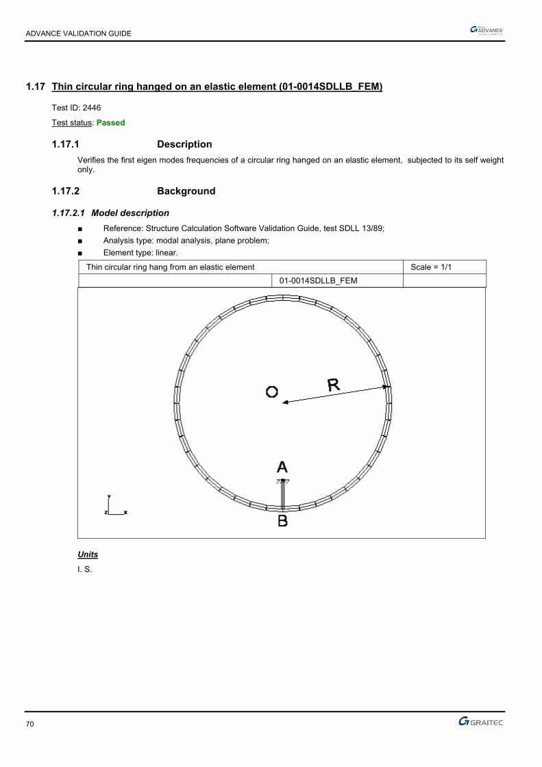
ADVANCE VALIDATION GUIDE
70
1.17 Thin circular ring hanged on an elastic element (01-0014SDLLB_FEM)
Test ID: 2446
Test status: Passed
1.17.1 Description
Verifies the first eigen modes frequencies of a circular ring hanged on an elastic element, subjected to its self weight only.
1.17.2 Background
1.17.2.1 Model description
■ Reference: Structure Calculation Software Validation Guide, test SDLL 13/89;
■ Analysis type: modal analysis, plane problem;
■ Element type: linear.
Thin circular ring hang from an elastic element Scale = 1/1
01-0014SDLLB_FEM
Units
I. S.

ADVANCE VALIDATION GUIDE
71
Geometry
■ Average radius of curvature: OB = R = 0.1 m,
■ Length of elastic element: AB = 0.0275 m ;
■ Straight rectangular section:
► Ring
Thickness: h = 0.005 m,
Width: b = 0.010 m,
Section: A = 5 x 10⁻⁵ m2,
Flexure moment of relative to the vertical axis: I = 1.042 x 10⁻¹⁰ m4,
► Elastic element
Thickness: h = 0.003 m,
Width: b = 0.010 m,
Section: A = 3 x 10⁻⁵ m2,
Flexure moment of inertia relative to the vertical axis: I = 2.25 x 10⁻¹¹ m4,
■ Points coordinates:
► O ( 0 ; 0 ),
► A ( 0 ; -0.0725 ),
► B ( 0 ; -0.1 ).
Materials properties
■ Longitudinal elastic modulus: E = 7.2 x 10¹⁰ Pa,
■ Poisson's ratio: = 0.3,
■ Density: = 2700 kg/m3.
Boundary conditions
■ Outer: Fixed in A,
■ Inner: None.
Loading
■ External: None,
■ Internal: None.
1.17.2.2 Eigen mode frequencies
Reference solutions
The reference solution was established from experimental results of a mass manufactured aluminum ring.
Finite elements modeling
■ Linear element: beam,
■ 43 nodes,
■ 43 linear elements.

ADVANCE VALIDATION GUIDE
72
Eigen mode shapes

ADVANCE VALIDATION GUIDE
73
1.17.2.3 Theoretical results
Solver Result name Result description Reference value
CM2 Eigen mode Eigen mode 1 Asymmetrical frequency [Hz] 28.80
CM2 Eigen mode Eigen mode 2 Symmetrical frequency [Hz] 189.30
CM2 Eigen mode Eigen mode 3 Asymmetrical frequency [Hz] 268.80
CM2 Eigen mode Eigen mode 4 Asymmetrical frequency [Hz] 641.00
CM2 Eigen mode Eigen mode 5 Symmetrical frequency [Hz] 682.00
CM2 Eigen mode Eigen mode 6 Asymmetrical frequency [Hz] 1063.00
1.17.3 Calculated results
Result name Result description Value Error
Eigen mode 1 Asymmetrical frequency [Hz] 28.81 Hz 0.03%
Eigen mode 2 Symmetrical frequency [Hz] 189.69 Hz 0.21%
Eigen mode 3 Asymmetrical frequency [Hz] 269.38 Hz 0.22%
Eigen mode 4 Asymmetrical frequency [Hz] 642.15 Hz 0.18%
Eigen mode 5 Symmetrical frequency [Hz] 683.9 Hz 0.28%
Eigen mode 6 Asymmetrical frequency [Hz] 1065.73 Hz 0.26%

ADVANCE VALIDATION GUIDE
74
1.18 Short beam on simple supports (eccentric) (01-0018SDLLB_FEM)
Test ID: 2450
Test status: Passed
1.18.1 Description
Verifies the first eigen mode frequencies of a short beam on simple supports (the supports are eccentric relative to the neutral axis).
1.18.2 Background
1.18.2.1 Model description
■ Reference: Structure Calculation Software Validation Guide, test SDLL 01/89;
■ Analysis type: modal analysis, (plane problem);
■ Element type: linear.
Short beam on simple supports (eccentric) Scale = 1/5
01-0018SDLLB_FEM
Units
I. S.
Geometry
■ Height: h = 0.2m,
■ Length: l = 1 m,
■ Width: b = 0.1 m,
■ Section: A = 2 x 10⁻² m4,
■ Flexure moment of inertia relative to z-axis: Iz = 6.667 x 10⁻⁵ m4.

ADVANCE VALIDATION GUIDE
75
Materials properties
■ Longitudinal elastic modulus: E = 2.1 x 10¹¹ Pa,
■ Poisson's ratio: = 0.3,
■ Density: = 7800 kg/m3.
Boundary conditions
■ Outer:
► Hinged at A (null horizontal and vertical displacements),
► Simple support at B.
■ Inner: None.
Loading
■ External: None.
■ Internal: None.
1.18.2.2 Eigen modes frequencies
Reference solution
The problem has no analytical solution, the solution is determined by averaging several software: Timoshenko model with shear force deformation effects and rotation inertia. The bending modes and the traction-compression are coupled.
Finite elements modeling
■ Linear element: S beam, imposed mesh,
■ 10 nodes,
■ 9 linear elements.
Eigen modes shape
Short beam on simple supports (eccentric)
Mode 1
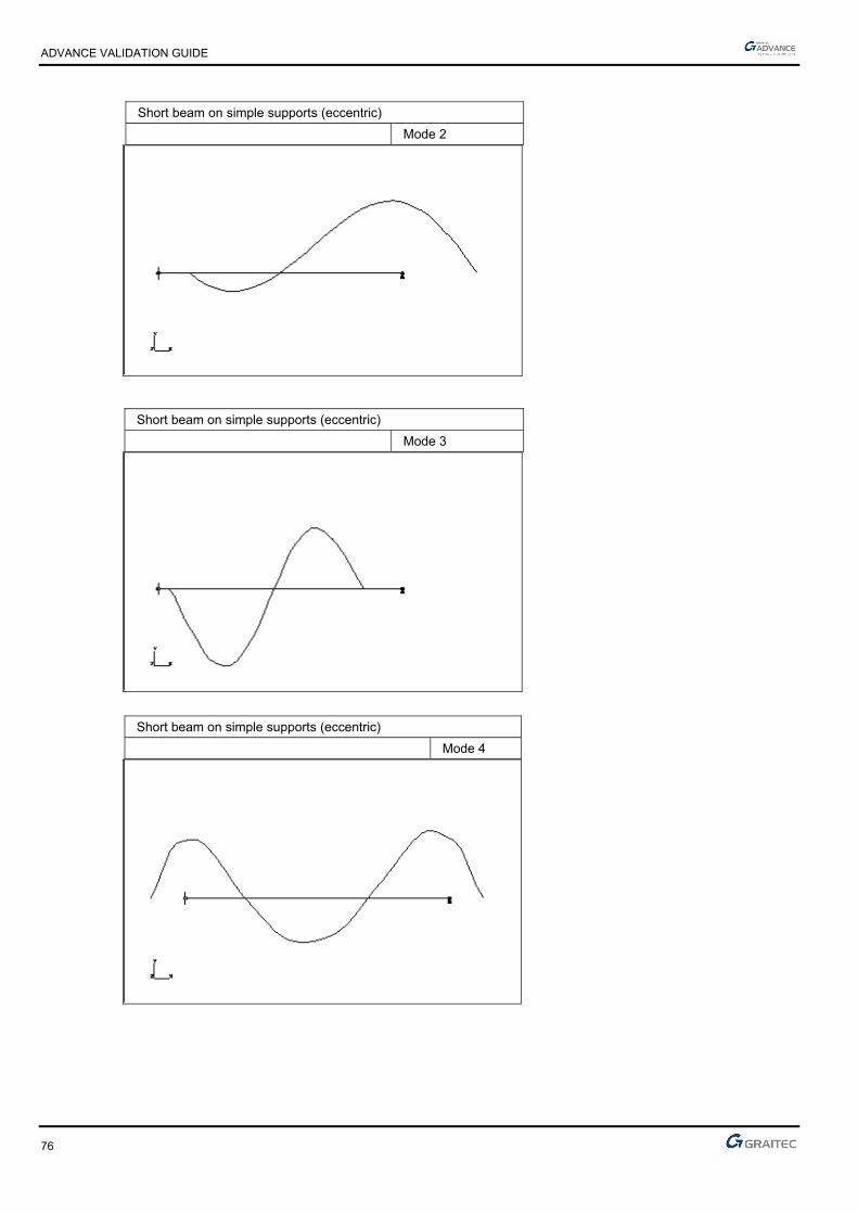
ADVANCE VALIDATION GUIDE
76
Short beam on simple supports (eccentric)
Mode 2
Short beam on simple supports (eccentric)
Mode 3
Short beam on simple supports (eccentric)
Mode 4

ADVANCE VALIDATION GUIDE
77
Short beam on simple supports (eccentric)
Mode 5
1.18.2.3 Theoretical results
Solver Result name Result description Reference value
CM2 Eigen mode Eigen mode 1 frequency [Hz] 392.8
CM2 Eigen mode Eigen mode 2 frequency [Hz] 902.2
CM2 Eigen mode Eigen mode 3 frequency [Hz] 1591.9
CM2 Eigen mode Eigen mode 4 frequency [Hz] 2629.2
CM2 Eigen mode Eigen mode 5 frequency [Hz] 3126.2
1.18.3 Calculated results
Result name Result description Value Error
Eigen mode 1 frequency [Hz] 393.7 Hz 0.23%
Eigen mode 2 frequency [Hz] 945.35 Hz 4.78%
Eigen mode 3 frequency [Hz] 1595.94 Hz 0.25%
Eigen mode 4 frequency [Hz] 2526.22 Hz -3.92%
Eigen mode 5 frequency [Hz] 3118.91 Hz -0.23%

ADVANCE VALIDATION GUIDE
78
1.19 Slender beam on two fixed supports (01-0024SSLLB_FEM)
Test ID: 2456
Test status: Passed
1.19.1 Description
A straight slender beam with fixed ends is loaded with a uniform load, several punctual loads and a torque. The shear force, bending moment, vertical displacement and horizontal reaction are verified.
1.19.2 Background
1.19.2.1 Model description
■ Reference: Structure Calculation Software Validation Guide, test SSLL 01/89;
■ Analysis type: linear static;
■ Element type: linear.
Slender beam on two fixed supports Scale = 1/4
01-0024SSLLB_FEM
Units
I. S.
Geometry
■ Length: L = 1 m,
■ Beam inertia: I = 1.7 x 10⁻⁸ m4.
Materials properties
■ Longitudinal elastic modulus: E = 2.1 x 10¹¹ Pa.

ADVANCE VALIDATION GUIDE
79
Boundary conditions
■ Outer: Fixed at A and B,
■ Inner: None.
Loading
■ External:
► Uniformly distributed load from A to B: py = p = -24000 N/m,
► Punctual load at D: Fx = F1 = 30000 N,
► Torque at D: Cz = C = -3000 Nm,
► Punctual load at E: Fx = F2 = 10000 N,
► Punctual load at E: Fy = F = -20000 N.
■ Internal: None.
1.19.2.2 Shear force at G
Reference solution
Analytical solution:
■ Shear force at G: VG
VG = 0.216F – 1.26 L
C
Finite elements modeling
■ Linear element: beam,
■ 5 nodes,
■ 4 linear elements.
Results shape
Slender beam on two fixed supports Scale = 1/5
Shear force

ADVANCE VALIDATION GUIDE
80
1.19.2.3 Bending moment in G
Reference solution
Analytical solution:
■ Bending moment at G: MG
MG = pL2
24 - 0.045LF – 0.3C
Finite elements modeling
■ Linear element: beam,
■ 5 nodes,
■ 4 linear elements.
Results shape
Slender beam on two fixed supports Scale = 1/5
Bending moment
1.19.2.4 Vertical displacement at G
Reference solution
Analytical solution:
■ Vertical displacement at G: vG
vG = pl4
384EI + 0.003375FL3
EI + 0.015CL2
EI
Finite elements modeling
■ Linear element: beam,
■ 5 nodes,
■ 4 linear elements.

ADVANCE VALIDATION GUIDE
81
Results shape
Slender beam on two fixed supports Scale = 1/4
Deformed
1.19.2.5 Horizontal reaction at A
Reference solution
Analytical solution:
■ Horizontal reaction at A: HA
HA = -0.7F1 –0.3F2
Finite elements modeling
■ Linear element: beam,
■ 5 nodes,
■ 4 linear elements.
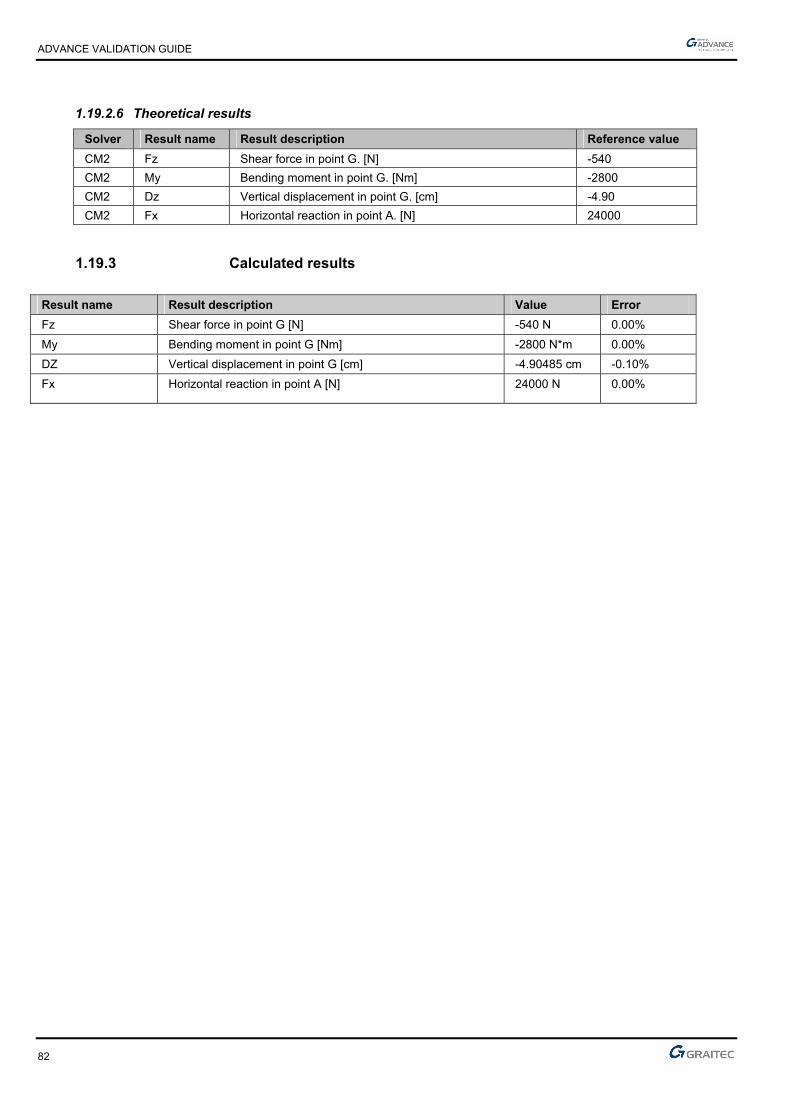
ADVANCE VALIDATION GUIDE
82
1.19.2.6 Theoretical results
Solver Result name Result description Reference value
CM2 Fz Shear force in point G. [N] -540
CM2 My Bending moment in point G. [Nm] -2800
CM2 Dz Vertical displacement in point G. [cm] -4.90
CM2 Fx Horizontal reaction in point A. [N] 24000
1.19.3 Calculated results
Result name Result description Value Error
Fz Shear force in point G [N] -540 N 0.00%
My Bending moment in point G [Nm] -2800 N*m 0.00%
DZ Vertical displacement in point G [cm] -4.90485 cm -0.10%
Fx Horizontal reaction in point A [N] 24000 N 0.00%
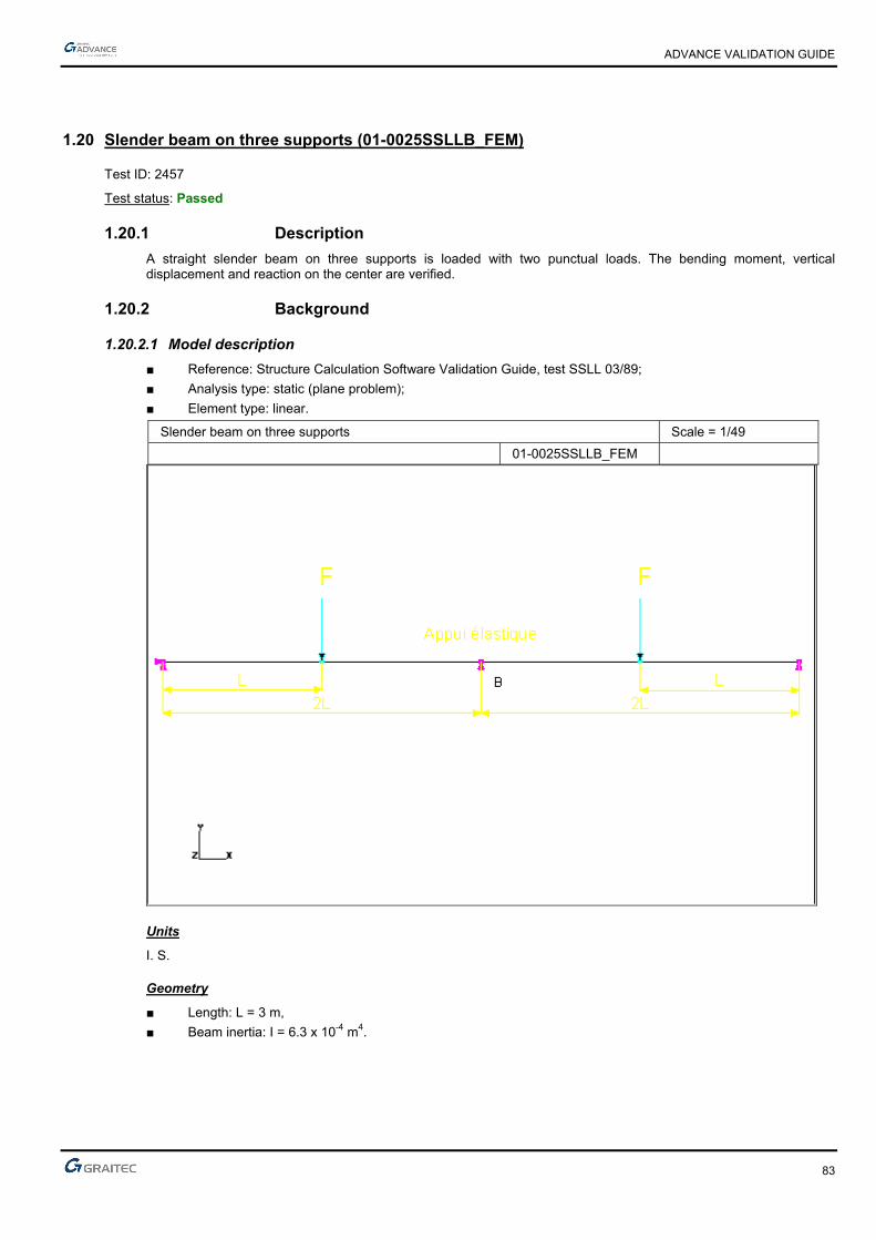
ADVANCE VALIDATION GUIDE
83
1.20 Slender beam on three supports (01-0025SSLLB_FEM)
Test ID: 2457
Test status: Passed
1.20.1 Description
A straight slender beam on three supports is loaded with two punctual loads. The bending moment, vertical displacement and reaction on the center are verified.
1.20.2 Background
1.20.2.1 Model description
■ Reference: Structure Calculation Software Validation Guide, test SSLL 03/89;
■ Analysis type: static (plane problem);
■ Element type: linear.
Slender beam on three supports Scale = 1/49
01-0025SSLLB_FEM
Units
I. S.
Geometry
■ Length: L = 3 m,
■ Beam inertia: I = 6.3 x 10⁻⁴ m4.
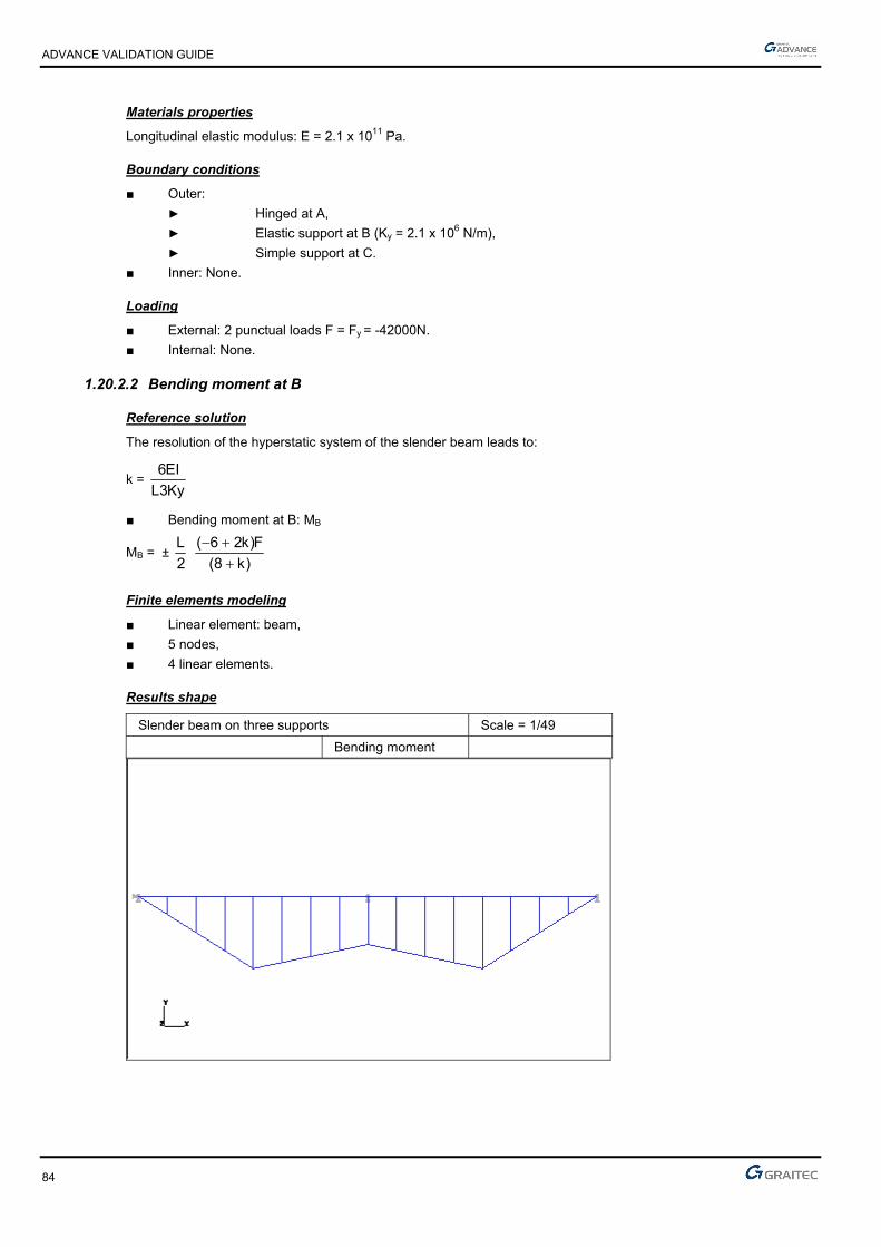
ADVANCE VALIDATION GUIDE
84
Materials properties
Longitudinal elastic modulus: E = 2.1 x 10¹¹ Pa.
Boundary conditions
■ Outer:
► Hinged at A,
► Elastic support at B (Ky = 2.1 x 10⁶ N/m),
► Simple support at C.
■ Inner: None.
Loading
■ External: 2 punctual loads F = Fy = -42000N.
■ Internal: None.
1.20.2.2 Bending moment at B
Reference solution
The resolution of the hyperstatic system of the slender beam leads to:
k = Ky3L
EI6
■ Bending moment at B: MB
MB = ± 2
L
)k8(
F)k26(
Finite elements modeling
■ Linear element: beam,
■ 5 nodes,
■ 4 linear elements.
Results shape
Slender beam on three supports Scale = 1/49
Bending moment

ADVANCE VALIDATION GUIDE
85
1.20.2.3 Reaction in B
Reference solution
■ Compression force in the spring: VB
VB = -11F8 + k
Finite elements modeling
■ Linear element: beam,
■ 5 nodes,
■ 4 linear elements.
1.20.2.4 Vertical displacement at B
Reference solution
■ Deflection at the spring location: vB
vB = 11F
Ky(8 + k)
Finite elements modeling
■ Linear element: beam,
■ 5 nodes,
■ 4 linear elements.
Results shape
Slender beam on three supports
Deformed

ADVANCE VALIDATION GUIDE
86
1.20.2.5 Theoretical results
Solver Result name Result description Reference value
CM2 My Bending moment in point B. [Nm] -63000
CM2 DZ Vertical displacement in point B. [cm] -1.00
CM2 Fz Reaction in point B. [N] -21000
1.20.3 Calculated results
Result name Result description Value Error
My Bending moment in point B [Nm] -63000 N*m 0.00%
DZ Vertical displacement in point B [cm] -1 cm 0.00%
Fz Reaction in point B [N] -21000 N 0.00%

ADVANCE VALIDATION GUIDE
87
1.21 Fixed thin arc in out of plane bending (01-0028SSLLB_FEM)
Test ID: 2460
Test status: Passed
1.21.1 Description
An arc of a circle fixed at one end is loaded with a punctual force at its free end, perpendicular to the plane. The out of plane displacement, torsion moment and bending moment are verified.
1.21.2 Background
1.21.2.1 Model description
■ Reference: Structure Calculation Software Validation Guide, test SSLL 07/89;
■ Analysis type: static linear;
■ Element type: linear.
Fixed thin arc in out of plane bending Scale = 1/6 01-0028SSLLB_FEM
Units
I. S.
Geometry
■ Medium radius: R = 1 m ,
■ Circular hollow section:
► de = 0.02 m,
► di = 0.016 m,
► A = 1.131 x 10⁻⁴ m2,
► Ix = 4.637 x 10⁻⁹ m4.
Materials properties
■ Longitudinal elastic modulus: E = 2 x 10¹¹ Pa,
■ Poisson's ratio: = 0.3.

ADVANCE VALIDATION GUIDE
88
Boundary conditions
■ Outer: Fixed at A.
■ Inner: None.
Loading
■ External: Punctual force in B perpendicular on the plane: Fz = F = 100 N.
■ Internal: None.
1.21.2.2 Displacements at B
Reference solution
Displacement out of plane at point B:
uB = FR3
EIx [
4 +
EIx KT
(34 - 2)]
where KT is the torsional rigidity for a circular section (torsion constant is 2Ix).
KT = 2GIx = EIx
1 + uB = FR3
EIx [
4 + (1 + ) (
34 - 2)]
Finite elements modeling
■ Linear element: beam,
■ 46 nodes,
■ 45 linear elements.
1.21.2.3 Moments at = 15°
Reference solution
■ Torsion moment: Mx’ = Mt = FR(1 - sin)
■ Bending moment: Mz’ = Mf = -FRcos
Finite elements modeling
■ Linear element: beam,
■ 46 nodes,
■ 45 linear elements.
1.21.2.4 Theoretical results
Solver Result name Result description Reference value
CM2 D Displacement out of plane in point B [m] 0.13462
CM2 Mx Torsion moment in = 15° [Nm] 74.1180
CM2 Mz Bending moment in = 15° [Nm] -96.5925
1.21.3 Calculated results
Result name Result description Value Error
D Displacement out of plane in point B [m] 0.135156 m 0.40%
Mx Torsion moment in Theta = 15° [Nm] 74.103 N*m -0.02%
Mz Bending moment in Theta = 15° [Nm] 96.5925 N*m 0.00%
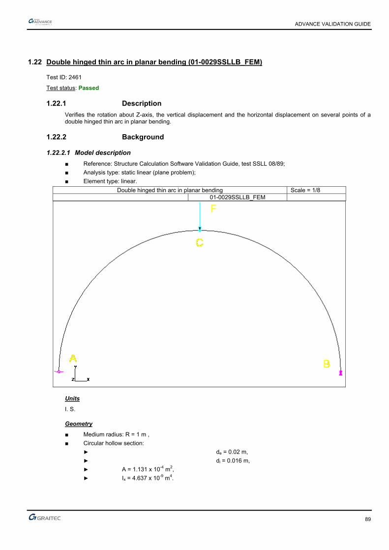
ADVANCE VALIDATION GUIDE
89
1.22 Double hinged thin arc in planar bending (01-0029SSLLB_FEM)
Test ID: 2461
Test status: Passed
1.22.1 Description
Verifies the rotation about Z-axis, the vertical displacement and the horizontal displacement on several points of a double hinged thin arc in planar bending.
1.22.2 Background
1.22.2.1 Model description
■ Reference: Structure Calculation Software Validation Guide, test SSLL 08/89;
■ Analysis type: static linear (plane problem);
■ Element type: linear.
Double hinged thin arc in planar bending Scale = 1/8 01-0029SSLLB_FEM
Units
I. S.
Geometry
■ Medium radius: R = 1 m ,
■ Circular hollow section:
► de = 0.02 m,
► di = 0.016 m,
► A = 1.131 x 10⁻⁴ m2,
► Ix = 4.637 x 10⁻⁹ m4.

ADVANCE VALIDATION GUIDE
90
Materials properties
■ Longitudinal elastic modulus: E = 2 x 10¹¹ Pa,
■ Poisson's ratio: = 0.3.
Boundary conditions
■ Outer:
► Hinge at A,
► At B: allowed rotation along z, vertical displacement restrained along y.
■ Inner: None.
Loading
■ External: Punctual load at C: Fy = F = - 100 N.
■ Internal: None.
1.22.2.2 Displacements at A, B and C
Reference solution
■ Rotation about z-axis
A = - B = ( 2 - 1)
FR22EI
■ Displacement;
Vertical at C: vC = 8
FREA + (
34 - 2)
FR3
2EI
Horizontal at B: uB = FR
2EA - FR3
2EI
Finite elements modeling
■ Linear element: beam,
■ 37 nodes,
■ 36 linear elements.

ADVANCE VALIDATION GUIDE
91
Displacements shape
Fixed thin arc in planar bending Scale = 1/11
Deformed
1.22.2.3 Theoretical results
Solver Result name Result description Reference value
CM2 RY Rotation about Z-axis in point A [rad] 0.030774
CM2 RY Rotation about Z-axis in point B [rad] -0.030774
CM2 DZ Vertical displacement in point C [cm] -1.9206
CM2 DX Horizontal displacement in point B [cm] 5.3912
1.22.3 Calculated results
Result name Result description Value Error
RY Rotation about Z-axis in point A [rad] 0.0307785 Rad 0.01%
RY Rotation about Z-axis in point B [rad] -0.0307785 Rad -0.01%
DZ Vertical displacement in point C [cm] -1.92019 cm 0.02%
DX Horizontal displacement in point B [cm] 5.386 cm -0.10%

ADVANCE VALIDATION GUIDE
92
1.23 Bending effects of a symmetrical portal frame (01-0023SDLLB_FEM)
Test ID: 2455
Test status: Passed
1.23.1 Description
Verifies the first eigen mode frequencies of a symmetrical portal frame with fixed supports.
1.23.2 Background
1.23.2.1 Model description
■ Reference: Structure Calculation Software Validation Guide, test SDLL 01/89;
■ Analysis type: modal analysis;
■ Element type: linear.
Bending effects of a symmetrical portal frame Scale = 1/5
01-0023SDLLB_FEM
Units
I. S.
Geometry
■ Straight rectangular sections for beams and columns:
■ Thickness: h = 0.0048 m,
■ Width: b = 0.029 m,
■ Section: A = 1.392 x 10⁻⁴ m2,
■ Flexure moment of inertia relative to z-axis: Iz = 2.673 x 10⁻¹⁰ m4,
■ Points coordinates in m:
A B C D E F x -0.30 0.30 -0.30 0.30 -0.30 0.30 y 0 0 0.36 0.36 0.81 0.81

ADVANCE VALIDATION GUIDE
93
Materials properties
■ Longitudinal elastic modulus: E = 2.1 x 10¹¹ Pa,
■ Poisson's ratio: = 0.3,
■ Density: = 7800 kg/m3.
Boundary conditions
■ Outer: Fixed at A and B,
■ Inner: None.
Loading
■ External: None.
■ Internal: None.
1.23.2.2 Eigen modes frequencies
Reference solution
Dynamic radius method (slender beams theory).
Finite elements modeling
■ Linear element: beam,
■ 60 nodes,
■ 60 linear elements.
Deformed shape
Bending effects of a symmetrical portal frame Scale = 1/7
Mode 13

ADVANCE VALIDATION GUIDE
94
1.23.2.3 Theoretical results
Solver Result name Result description Reference value
CM2 Eigen mode Eigen mode 1 antisymmetric frequency [Hz] 8.8
CM2 Eigen mode Eigen mode 2 antisymmetric frequency [Hz] 29.4
CM2 Eigen mode Eigen mode 3 symmetric frequency [Hz] 43.8
CM2 Eigen mode Eigen mode 4 symmetric frequency [Hz] 56.3
CM2 Eigen mode Eigen mode 5 antisymmetric frequency [Hz] 96.2
CM2 Eigen mode Eigen mode 6 symmetric frequency [Hz] 102.6
CM2 Eigen mode Eigen mode 7 antisymmetric frequency [Hz] 147.1
CM2 Eigen mode Eigen mode 8 symmetric frequency [Hz] 174.8
CM2 Eigen mode Eigen mode 9 antisymmetric frequency [Hz] 178.8
CM2 Eigen mode Eigen mode 10 antisymmetric frequency [Hz] 206
CM2 Eigen mode Eigen mode 11 symmetric frequency [Hz] 266.4
CM2 Eigen mode Eigen mode 12 antisymmetric frequency [Hz] 320
CM2 Eigen mode Eigen mode 13 symmetric frequency [Hz] 335
1.23.3 Calculated results
Result name Result description Value Error
Eigen mode 1 antisymmetric frequency [Hz] 8.78 Hz -0.23%
Eigen mode 2 antisymmetric frequency [Hz] 29.43 Hz 0.10%
Eigen mode 3 symmetric frequency [Hz] 43.85 Hz 0.11%
Eigen mode 4 symmetric frequency [Hz] 56.3 Hz 0.00%
Eigen mode 5 antisymmetric frequency [Hz] 96.05 Hz -0.16%
Eigen mode 6 symmetric frequency [Hz] 102.7 Hz 0.10%
Eigen mode 7 antisymmetric frequency [Hz] 147.08 Hz -0.01%
Eigen mode 8 symmetric frequency [Hz] 174.96 Hz 0.09%
Eigen mode 9 antisymmetric frequency [Hz] 178.92 Hz 0.07%
Eigen mode 10 antisymmetric frequency [Hz] 206.23 Hz 0.11%
Eigen mode 11 symmetric frequency [Hz] 266.62 Hz 0.08%
Eigen mode 12 antisymmetric frequency [Hz] 319.95 Hz -0.02%
Eigen mode 13 symmetric frequency [Hz] 334.96 Hz -0.01%

ADVANCE VALIDATION GUIDE
95
1.24 Fixed thin arc in planar bending (01-0027SSLLB_FEM)
Test ID: 2459
Test status: Passed
1.24.1 Description
Arc of a circle fixed at one end, subjected to two punctual loads and a torque at its free end. The horizontal displacement, vertical displacement and rotation about Z-axis are verified.
1.24.2 Background
1.24.2.1 Model description
■ Reference: Structure Calculation Software Validation Guide, test SSLL 06/89;
■ Analysis type: static linear (plane problem);
■ Element type: linear.
Fixed thin arc in planar bending Scale = 1/24 01-0027SSLLB_FEM
Units
I. S.
Geometry
■ Medium radius: R = 3 m ,
■ Circular hollow section:
► de = 0.02 m,
► di = 0.016 m,
► A = 1.131 x 10⁻⁴ m2,
► Ix = 4.637 x 10⁻⁹ m4.

ADVANCE VALIDATION GUIDE
96
Materials properties
Longitudinal elastic modulus: E = 2 x 10¹¹ Pa.
Boundary conditions
■ Outer: Fixed in A.
■ Inner: None.
Loading
■ External:
At B:
► punctual load F1 = Fx = 10 N,
► punctual load F2 = Fy = 5 N,
► bending moment about Oz, Mz = 8 Nm.
■ Internal: None.
1.24.2.2 Displacements at B
Reference solution
At point B:
■ displacement parallel to Ox: u = R2
4EI [F1R + 2F2R + 4Mz]
■ displacement parallel to Oy: v = R2
4EI [2F1R + (3 - 8)F2R + 2( - 2)Mz]
■ rotation around Oz: = R
4EI [4F1R + 2( - 2)F2R + 2Mz]
Finite elements modeling
■ Linear element: beam,
■ 31 nodes,
■ 30 linear elements.
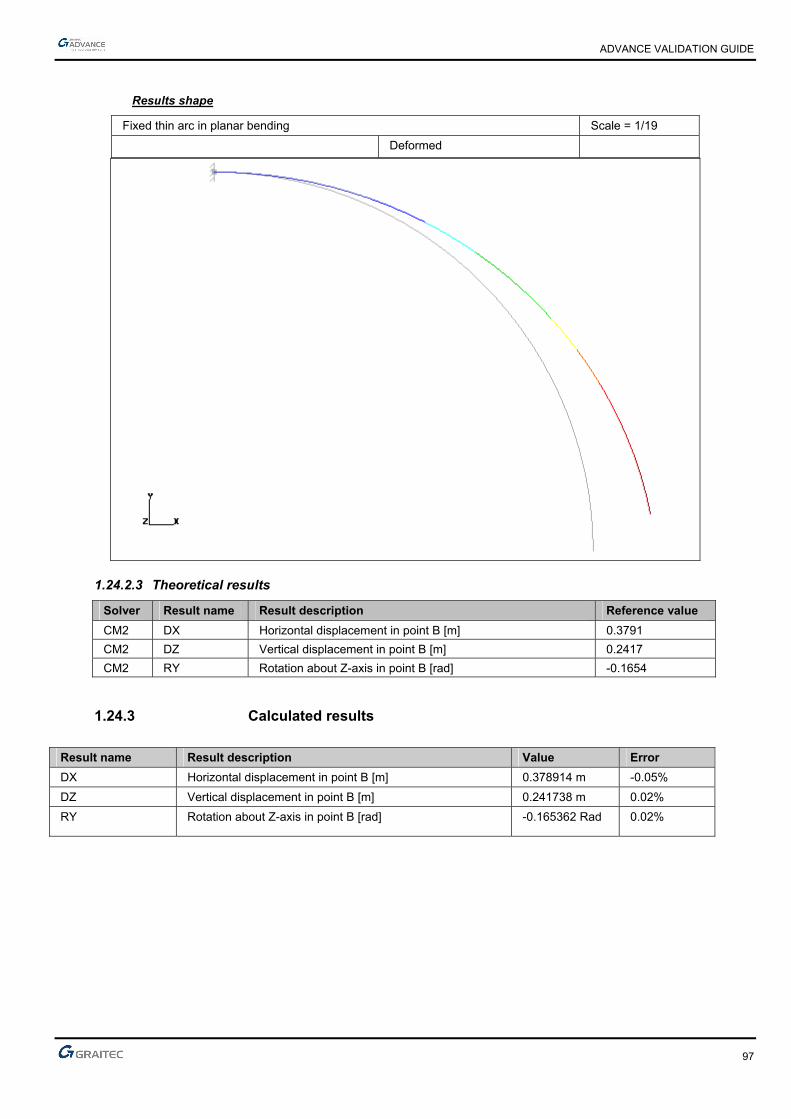
ADVANCE VALIDATION GUIDE
97
Results shape
Fixed thin arc in planar bending Scale = 1/19
Deformed
1.24.2.3 Theoretical results
Solver Result name Result description Reference value
CM2 DX Horizontal displacement in point B [m] 0.3791
CM2 DZ Vertical displacement in point B [m] 0.2417
CM2 RY Rotation about Z-axis in point B [rad] -0.1654
1.24.3 Calculated results
Result name Result description Value Error
DX Horizontal displacement in point B [m] 0.378914 m -0.05%
DZ Vertical displacement in point B [m] 0.241738 m 0.02%
RY Rotation about Z-axis in point B [rad] -0.165362 Rad 0.02%

ADVANCE VALIDATION GUIDE
98
1.25 Beam on elastic soil, free ends (01-0032SSLLB_FEM)
Test ID: 2464
Test status: Passed
1.25.1 Description
A beam under 3 punctual loads lays on a soil of constant linear stiffness. The bending moment, vertical displacement and rotation about z-axis on several points of the beam are verified.
1.25.2 Background
1.25.2.1 Model description
■ Reference: Structure Calculation Software Validation Guide, test SSLL 15/89;
■ Analysis type: static linear (plane problem);
■ Element type: linear.
Beam on elastic soil, free ends Scale = 1/21 01-0032SSLLB_FEM
Units
I. S.
Geometry
■ L = ( 10 )/2,
■ I = 10-4 m4.
Materials properties
Longitudinal elastic modulus: E = 2.1 x 10¹¹ Pa.
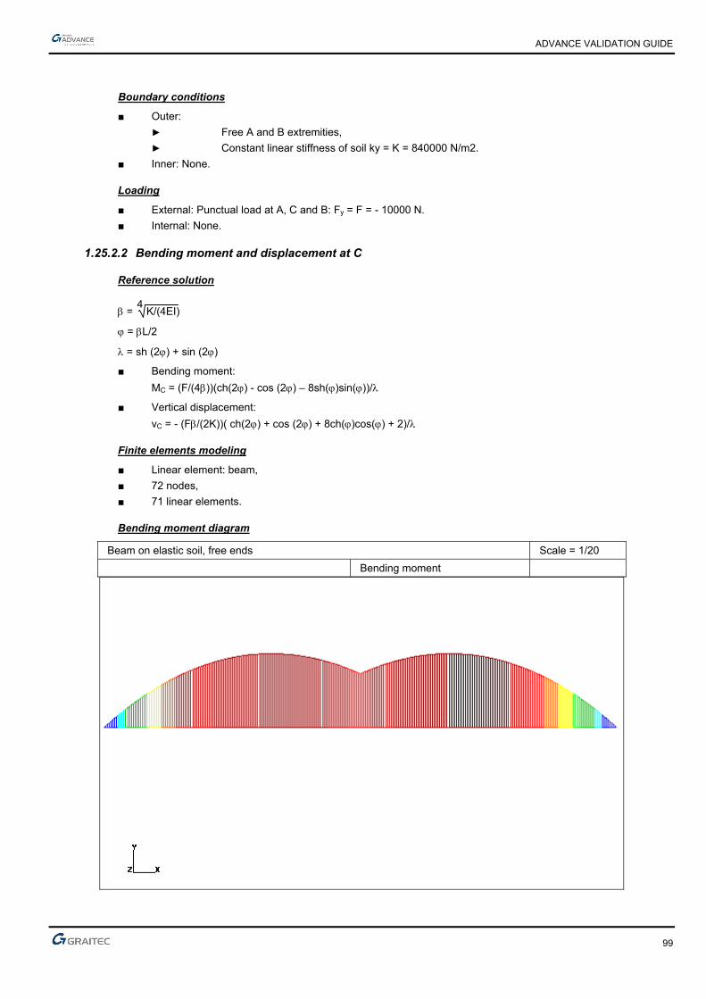
ADVANCE VALIDATION GUIDE
99
Boundary conditions
■ Outer:
► Free A and B extremities,
► Constant linear stiffness of soil ky = K = 840000 N/m2.
■ Inner: None.
Loading
■ External: Punctual load at A, C and B: Fy = F = - 10000 N.
■ Internal: None.
1.25.2.2 Bending moment and displacement at C
Reference solution
= 4
K/(4EI)
= L/2
= sh (2) + sin (2)
■ Bending moment:
MC = (F/(4))(ch(2) - cos (2) – 8sh()sin())/
■ Vertical displacement:
vC = - (F/(2K))( ch(2) + cos (2) + 8ch()cos() + 2)/
Finite elements modeling
■ Linear element: beam,
■ 72 nodes,
■ 71 linear elements.
Bending moment diagram
Beam on elastic soil, free ends Scale = 1/20
Bending moment

ADVANCE VALIDATION GUIDE
100
1.25.2.3 Displacements at A
Reference solution
■ Vertical displacement:
vA = (2F/K)( ch()cos() + ch(2) + cos(2))/
■ Rotation about z-axis
A = (-2F2/K)( sh()cos() - sin()ch() + sh(2) - sin(2))/
Finite elements modeling
■ Linear element: beam,
■ 72 nodes,
■ 71 linear elements
1.25.2.4 Theoretical results
Solver Result name Result description Reference value
CM2 My Bending moment in point C [Nm] 5759
CM2 Dz Vertical displacement in point C [m] -0.006844
CM2 Dz Vertical displacement in point A [m] -0.007854
CM2 RY Rotation about z-axis in point A [rad] -0.000706
1.25.3 Calculated results
Result name Result description Value Error
My Bending moment in point C [Nm] 5779.54 N*m 0.36%
Dz Vertical displacement in point C [m] -0.00684369 m 0.00%
Dz Vertical displacement in point A [m] -0.00786073 m -0.09%
RY Rotation Theta about z-axis in point A [rad] -0.000707427 Rad -0.20%

ADVANCE VALIDATION GUIDE
101
1.26 EDF Pylon (01-0033SFLLA_FEM)
Test ID: 2465
Test status: Passed
1.26.1 Description
Verifies the displacement at the top of an EDF Pylon and the dominating buckling results. Three punctual loads corresponding to wind loads are applied on the main arms, on the upper arm and on the lower horizontal frames of the pylon.
1.26.2 Background
1.26.2.1 Model description
■ Reference: Internal GRAITEC test;
■ Analysis type: static linear, Eulerian buckling;
■ Element type: linear
Units
I. S.
Geometry
Materials properties
■ Longitudinal elastic modulus: E = 2.1 x 10¹¹ Pa,
■ Poisson's ratio: = 0.3.
Boundary conditions
■ Outer:
► Hinged support,
► For the modeling, a fixed restraint and 4 beams were added at the pylon supports level.
■ Inner: None.

ADVANCE VALIDATION GUIDE
102
Loading
■ External:
Punctual loads corresponding to a wind load.
► FX = 165550 N, FY = - 1240 N, FZ = - 58720 N on the main arms,
► FX = 50250 N, FY = - 1080 N, FZ = - 12780 N on the upper arm,
► FX = 11760 N, FY = 0 N, FZ = 0 N on the lower horizontal frames
■ Internal: None.
1.26.2.2 Displacement of the model in the linear elastic range
Reference solution

ADVANCE VALIDATION GUIDE
103
Software ANSYS 5.3 NE/NASTRAN 7.0 Max deflection (m) 0.714 0.714 dominating mode 2.77 2.77
Finite elements modeling
■ Linear element: beam, imposed mesh,
■ 402 nodes,
■ 1034 elements.
Deformed shape

ADVANCE VALIDATION GUIDE
104
Buckling modal deformation (dominating mode)
1.26.2.3 Theoretical results
Solver Result name Result description Reference value
CM2 D Displacement at the top of the pylon [m] 0.714
CM2 Dominating buckling - critical , mode 4 [Hz] 2.77
1.26.3 Calculated results
Result name Result description Value Error
D Displacement at the top of the pylon [m] 0.71254 m -0.20%
Dominating buckling - critical Lambda - mode 4 [Hz] 2.83 Hz 2.17%

ADVANCE VALIDATION GUIDE
105
1.27 Truss with hinged bars under a punctual load (01-0031SSLLB_FEM)
Test ID: 2463
Test status: Passed
1.27.1 Description
Verifies the horizontal and the vertical displacement in several points of a truss with hinged bars, subjected to a punctual load.
1.27.2 Background
■ Reference: Structure Calculation Software Validation Guide, test SSLL 11/89;
■ Analysis type: static linear (plane problem);
■ Element type: linear.
1.27.2.1 Model description
Truss with hinged bars under a punctual load Scale = 1/10
01-0031SSLLB_FEM
Units
I. S.
Geometry
Elements Length (m) Area (m2) AC 0.5 2 2 x 10⁻⁴
CB 0.5 2 2 x 10⁻⁴
CD 2.5 1 x 10⁻⁴
BD 2 1 x 10⁻⁴
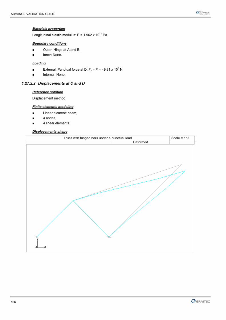
ADVANCE VALIDATION GUIDE
106
Materials properties
Longitudinal elastic modulus: E = 1.962 x 10¹¹ Pa.
Boundary conditions
■ Outer: Hinge at A and B,
■ Inner: None.
Loading
■ External: Punctual force at D: Fy = F = - 9.81 x 10³ N.
■ Internal: None.
1.27.2.2 Displacements at C and D
Reference solution
Displacement method.
Finite elements modeling
■ Linear element: beam,
■ 4 nodes,
■ 4 linear elements.
Displacements shape
Truss with hinged bars under a punctual load Scale = 1/9 Deformed

ADVANCE VALIDATION GUIDE
107
1.27.2.3 Theoretical results
Solver Result name Result description Reference value
CM2 DX Horizontal displacement in point C [mm] 0.26517
CM2 DX Horizontal displacement in point D [mm] 3.47902
CM2 DZ Vertical displacement in point C [mm] 0.08839
CM2 DZ Vertical displacement in point D [mm] -5.60084
1.27.3 Calculated results
Result name Result description Value Error
DX Horizontal displacement in point C [mm] 0.264693 mm -0.18%
DX Horizontal displacement in point D [mm] 3.47531 mm -0.11%
DZ Vertical displacement in point C [mm] 0.0881705 mm -0.25%
DZ Vertical displacement in point D [mm] -5.595 mm 0.10%
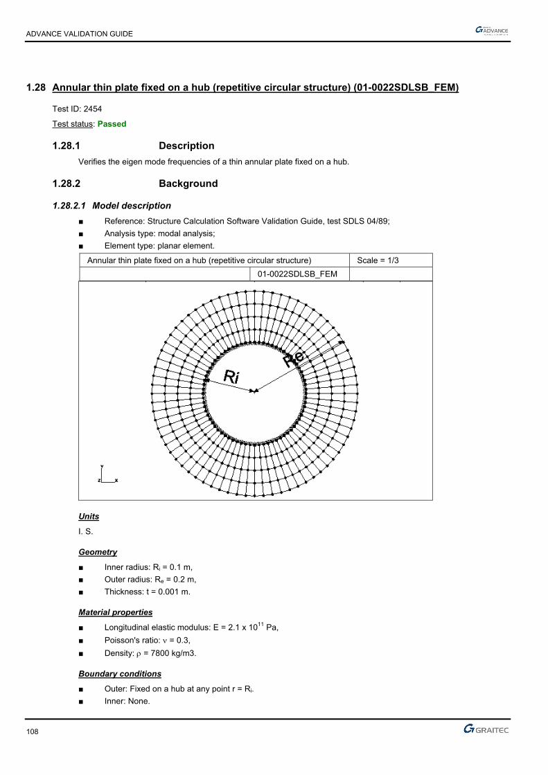
ADVANCE VALIDATION GUIDE
108
1.28 Annular thin plate fixed on a hub (repetitive circular structure) (01-0022SDLSB_FEM)
Test ID: 2454
Test status: Passed
1.28.1 Description
Verifies the eigen mode frequencies of a thin annular plate fixed on a hub.
1.28.2 Background
1.28.2.1 Model description
■ Reference: Structure Calculation Software Validation Guide, test SDLS 04/89;
■ Analysis type: modal analysis;
■ Element type: planar element.
Annular thin plate fixed on a hub (repetitive circular structure) Scale = 1/3
01-0022SDLSB_FEM
Units
I. S.
Geometry
■ Inner radius: Ri = 0.1 m,
■ Outer radius: Re = 0.2 m,
■ Thickness: t = 0.001 m.
Material properties
■ Longitudinal elastic modulus: E = 2.1 x 10¹¹ Pa,
■ Poisson's ratio: = 0.3,
■ Density: = 7800 kg/m3.
Boundary conditions
■ Outer: Fixed on a hub at any point r = Ri.
■ Inner: None.

ADVANCE VALIDATION GUIDE
109
Loading
■ External: None.
■ Internal: None.
1.28.2.2 Eigen modes frequencies
Reference solution
The solution of determining the frequency based on Bessel functions leads to the following formula:
fij = 1
2Re2 ij
2 Et2
12(1-2)
where:
i = the number of nodal diameters
j = the number of nodal circles
and ij2 such as:
j \ i 0 1 2 3 0 13.0 13.3 14.7 18.5 1 85.1 86.7 91.7 100
Finite elements modeling
■ Planar element: plate,
■ 360 nodes,
■ 288 planar elements.
1.28.2.3 Theoretical results
Solver Result name Result description Reference value
CM2 Eigen mode Eigen mode “i" - “j” frequency, for i = 0; j = 0. [Hz] 79.26
CM2 Eigen mode Eigen mode “i" - “j” frequency, for i = 0; j = 1. [Hz] 518.85
CM2 Eigen mode Eigen mode “i" - “j” frequency, for i = 1; j = 0. [Hz] 81.09
CM2 Eigen mode Eigen mode “i" - “j” frequency, for i = 1; j = 1. [Hz] 528.61
CM2 Eigen mode Eigen mode “i" - “j” frequency, for i = 2; j = 0. [Hz] 89.63
CM2 Eigen mode Eigen mode “i" - “j” frequency, for i = 2; j = 1. [Hz] 559.09
CM2 Eigen mode Eigen mode “i" - “j” frequency, for i = 3; j = 0. [Hz] 112.79
CM2 Eigen mode Eigen mode “i" - “j” frequency, for i = 3; j = 1. [Hz] 609.70
1.28.3 Calculated results
Result name Result description Value Error
Eigen mode "i" - "j" frequency, for i = 0; j = 0 (Mode 1) [Hz] 79.05 Hz -0.26%
Eigen mode "i" - "j" frequency, for i = 0; j = 1 (Mode 18) [Hz] 521.84 Hz 0.58%
Eigen mode "i" - "j" frequency, for i = 1; j = 0 (Mode 2) [Hz] 80.52 Hz -0.70%
Eigen mode "i" - "j" frequency, for i = 1; j = 1 (Mode 20) [Hz] 529.49 Hz 0.17%
Eigen mode "i" - "j" frequency, for i = 2; j = 0 (Mode 4) [Hz] 88.43 Hz -1.34%
Eigen mode “i" - “j” frequency, for i = 2; j = 1 (Mode 22) [Hz] 552.43 Hz -1.19%
Eigen mode "i" - "j" frequency, for i = 3; j = 0 (Mode 7) [Hz] 110.27 Hz -2.23%
Eigen mode "i" - "j" frequency, for i = 3; j = 1 (Mode 25) [Hz] 593.83 Hz -2.60%
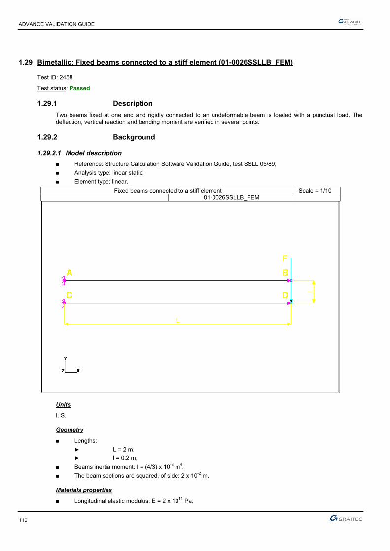
ADVANCE VALIDATION GUIDE
110
1.29 Bimetallic: Fixed beams connected to a stiff element (01-0026SSLLB_FEM)
Test ID: 2458
Test status: Passed
1.29.1 Description
Two beams fixed at one end and rigidly connected to an undeformable beam is loaded with a punctual load. The deflection, vertical reaction and bending moment are verified in several points.
1.29.2 Background
1.29.2.1 Model description
■ Reference: Structure Calculation Software Validation Guide, test SSLL 05/89;
■ Analysis type: linear static;
■ Element type: linear.
Fixed beams connected to a stiff element Scale = 1/10 01-0026SSLLB_FEM
Units
I. S.
Geometry
■ Lengths:
► L = 2 m,
► l = 0.2 m,
■ Beams inertia moment: I = (4/3) x 10-8 m4,
■ The beam sections are squared, of side: 2 x 10⁻² m.
Materials properties
■ Longitudinal elastic modulus: E = 2 x 10¹¹ Pa.

ADVANCE VALIDATION GUIDE
111
Boundary conditions
■ Outer: Fixed in A and C,
■ Inner: The tangents to the deflection of beams AB and CD at B and D remain horizontal; practically, we restraint translations along x and z at nodes B and D.
Loading
■ External: In D: punctual load F = Fy = -1000N.
■ Internal: None.
1.29.2.2 Deflection at B and D
Reference solution
The theory of slender beams bending (Euler-Bernouilli formula) leads to a deflection at B and D:
The resolution of the hyperstatic system of the slender beam leads to:
vB = vD = FL3
24EI
Finite elements modeling
■ Linear element: beam,
■ 4 nodes,
■ 3 linear elements.
Results shape
Fixed beams connected to a stiff element Scale = 1/10 Deformed
1.29.2.3 Vertical reaction at A and C
Reference solution
Analytical solution.
Finite elements modeling
■ Linear element: beam,
■ 4 nodes,
■ 3 linear elements.

ADVANCE VALIDATION GUIDE
112
1.29.2.4 Bending moment at A and C
Reference solution
Analytical solution.
Finite elements modeling
■ Linear element: beam,
■ 4 nodes,
■ 3 linear elements
1.29.2.5 Theoretical results
Solver Result name Result description Reference value
CM2 D Deflection in point B [m] 0.125
CM2 D Deflection in point D [m] 0.125
CM2 Fz Vertical reaction in point A [N] -500
CM2 Fz Vertical reaction in point C [N] -500
CM2 My Bending moment in point A [Nm] 500
CM2 My Bending moment in point C [Nm] 500
1.29.3 Calculated results
Result name Result description Value Error
D Deflection in point B [m] 0.125376 m 0.30%
D Deflection in point D [m] 0.125376 m 0.30%
Fz Vertical reaction in point A [N] -500 N 0.00%
Fz Vertical reaction in point C [N] -500 N 0.00%
My Bending moment in point A [Nm] 500.083 N*m 0.02%
My Bending moment in point C [Nm] 500.083 N*m 0.02%
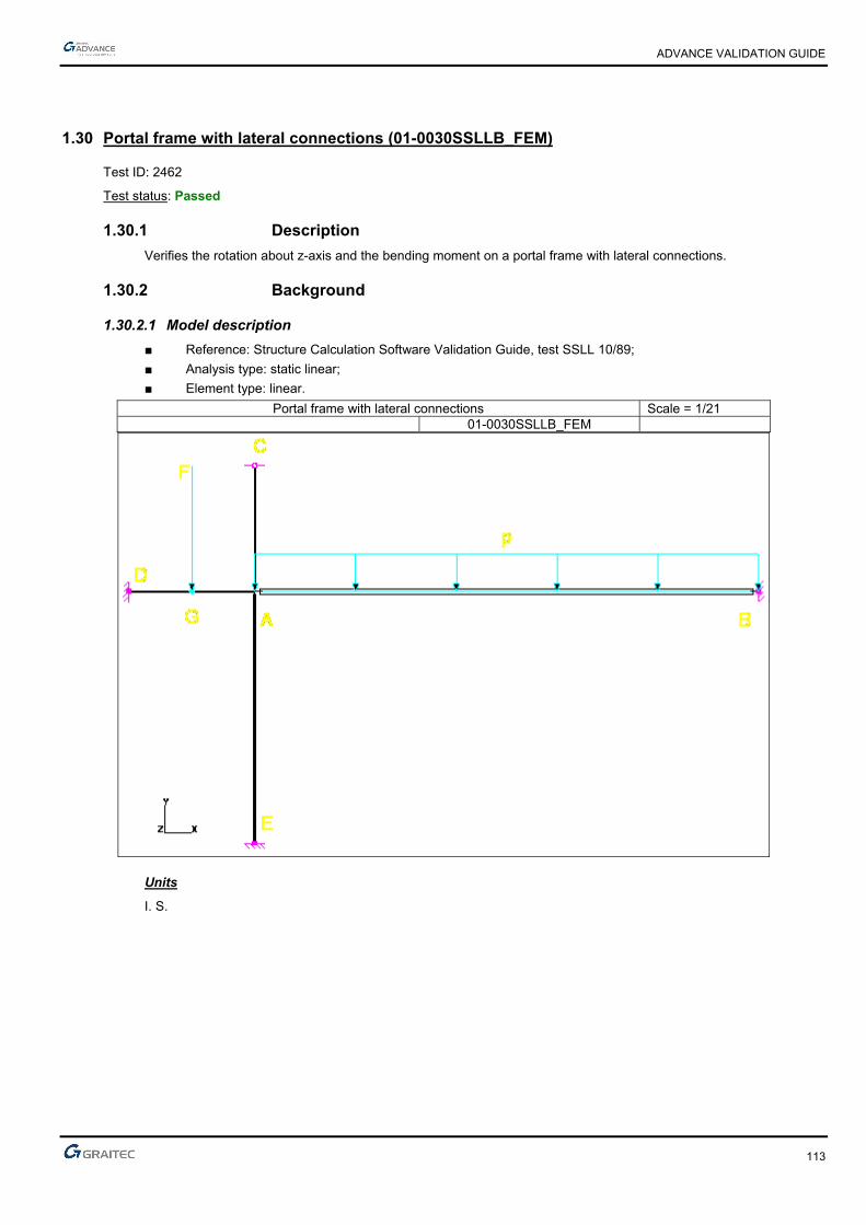
ADVANCE VALIDATION GUIDE
113
1.30 Portal frame with lateral connections (01-0030SSLLB_FEM)
Test ID: 2462
Test status: Passed
1.30.1 Description
Verifies the rotation about z-axis and the bending moment on a portal frame with lateral connections.
1.30.2 Background
1.30.2.1 Model description
■ Reference: Structure Calculation Software Validation Guide, test SSLL 10/89;
■ Analysis type: static linear;
■ Element type: linear.
Portal frame with lateral connections Scale = 1/21 01-0030SSLLB_FEM
Units
I. S.
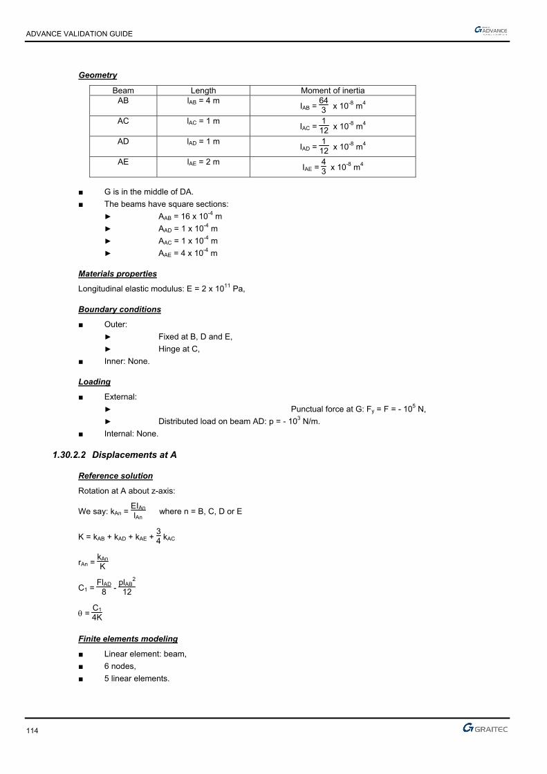
ADVANCE VALIDATION GUIDE
114
Geometry
Beam Length Moment of inertia AB lAB = 4 m
IAB = 643 x 10-8 m4
AC lAC = 1 m IAC =
112 x 10-8 m4
AD lAD = 1 m IAD =
112 x 10-8 m4
AE lAE = 2 m IAE =
43 x 10-8 m4
■ G is in the middle of DA.
■ The beams have square sections:
► AAB = 16 x 10-4 m
► AAD = 1 x 10⁻⁴ m
► AAC = 1 x 10⁻⁴ m
► AAE = 4 x 10⁻⁴ m
Materials properties
Longitudinal elastic modulus: E = 2 x 10¹¹ Pa,
Boundary conditions
■ Outer:
► Fixed at B, D and E,
► Hinge at C,
■ Inner: None.
Loading
■ External:
► Punctual force at G: Fy = F = - 105 N,
► Distributed load on beam AD: p = - 103 N/m.
■ Internal: None.
1.30.2.2 Displacements at A
Reference solution
Rotation at A about z-axis:
We say: kAn = EIAn
lAn where n = B, C, D or E
K = kAB + kAD + kAE + 34 kAC
rAn = kAn
K
C1 = FlAD
8 - plAB
2
12
= C1
4K
Finite elements modeling
■ Linear element: beam,
■ 6 nodes,
■ 5 linear elements.

ADVANCE VALIDATION GUIDE
115
Displacements shape
Portal frame with lateral connections
Deformed
1.30.2.3 Moments in A
Reference solution
■ MAB = plAB
2
12 + rAB x C1
■ MAD = - FlAD
8 + rAD x C1
■ MAE = rAE x C1
■ MAC = rAC x C1
Finite elements modeling
■ Linear element: beam,
■ 6 nodes,
■ 5 linear elements
1.30.2.4 Theoretical results
Solver Result name Result description Reference value
CM2 RY Rotation about z-axis in point A [rad] -0.227118
CM2 My Bending moment in point A (MAB) [Nm] 11023.72
CM2 My Bending moment in point A (MAC) [Nm] 113.559
CM2 My Bending moment in point A (MAD) [Nm] 12348.588
CM2 My Bending moment in point A (MAE) [Nm] 1211.2994
1.30.3 Calculated results
Result name Result description Value Error
RY Rotation Theta about z-axis in point A [rad] -0.227401 Rad -0.12%
My Bending moment in point A (Moment AB) [Nm] 11021 N*m -0.02%
My Bending moment in point A (Moment AC) [Nm] 113.704 N*m 0.13%
My Bending moment in point A (Moment AD) [Nm] 12347.5 N*m -0.01%
My Bending moment in point A (Moment AE) [Nm] 1212.77 N*m 0.12%
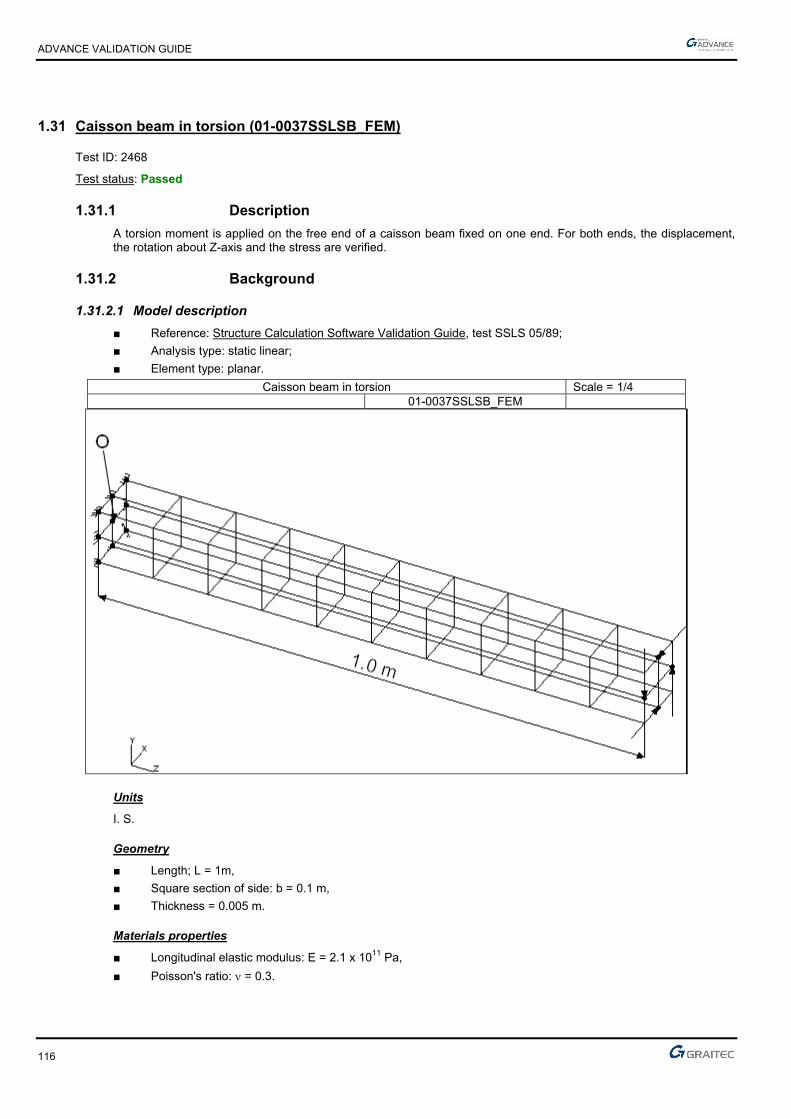
ADVANCE VALIDATION GUIDE
116
1.31 Caisson beam in torsion (01-0037SSLSB_FEM)
Test ID: 2468
Test status: Passed
1.31.1 Description
A torsion moment is applied on the free end of a caisson beam fixed on one end. For both ends, the displacement, the rotation about Z-axis and the stress are verified.
1.31.2 Background
1.31.2.1 Model description
■ Reference: Structure Calculation Software Validation Guide, test SSLS 05/89;
■ Analysis type: static linear;
■ Element type: planar.
Caisson beam in torsion Scale = 1/4 01-0037SSLSB_FEM
Units
I. S.
Geometry
■ Length; L = 1m,
■ Square section of side: b = 0.1 m,
■ Thickness = 0.005 m.
Materials properties
■ Longitudinal elastic modulus: E = 2.1 x 10¹¹ Pa,
■ Poisson's ratio: = 0.3.

ADVANCE VALIDATION GUIDE
117
Boundary conditions
■ Outer: Beam fixed at end x = 0;
■ Inner: None.
Loading
■ External: Torsion moment M = 10N.m applied to the free end (for modeling, 4 forces of 50 N).
■ Internal: None.
1.31.2.2 Displacement and stress at two points
Reference solution
The reference solution is determined by averaging the results of several calculation software with implemented finite elements method.
Points coordinates:
■ A (0,0.05,0.5)
■ B (-0.05,0,0.8)
Note: point O is the origin of the coordinate system (x,y,z).
Finite elements modeling
■ Planar element: shell,
■ 90 nodes,
■ 88 planar elements.
Deformed shape
Caisson beam in torsion Scale = 1/4 Deformed
ADVANCE VALIDATION GUIDE
118
1.31.2.3 Theoretical results
Solver Result name Result description Reference value
CM2 D Displacement in point A [m] -0.617 x 10⁻⁶
CM2 D Displacement in point B [m] -0.987 x 10⁻⁶
CM2 RY Rotation about Z-axis in point A [rad] 0.123 x 10⁻⁴
CM2 RY Rotation about Z-axis in point B [rad] 0.197 x 10⁻⁴
CM2 sxy_mid xy stress in point A [MPa] -0.11
CM2 sxy_mid xy stress in point B [MPa] -0.11
1.31.3 Calculated results
Result name Result description Value Error
D Displacement in point A [µm] 0.615909 µm -0.18%
D Displacement in point B [µm] 0.986806 µm -0.02%
RY Rotation about Z-axis in point A [rad] -1.23211e-005 Rad -0.17%
RY Rotation about Z-axis in point B [rad] -1.97172e-005 Rad -0.09%
sxy_mid Sigma xy stress in point A [MPa] -0.100037 MPa -0.04%
sxy_mid Sigma xy stress in point B [MPa] -0.100212 MPa -0.21%
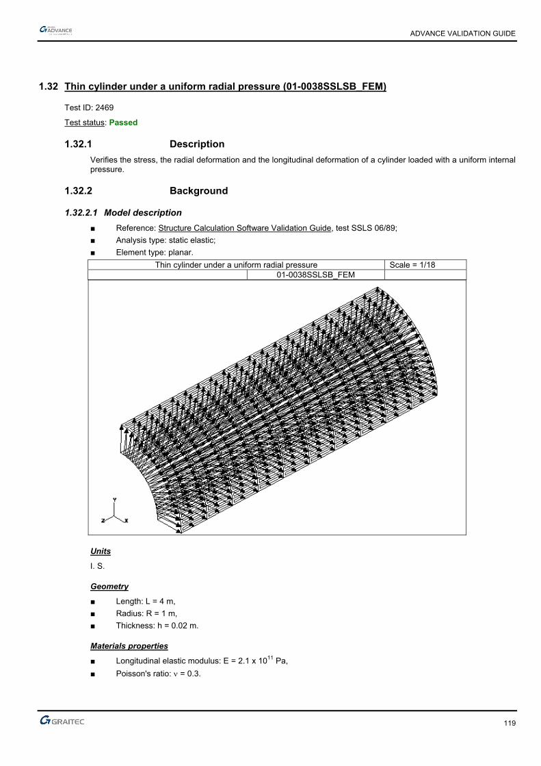
ADVANCE VALIDATION GUIDE
119
1.32 Thin cylinder under a uniform radial pressure (01-0038SSLSB_FEM)
Test ID: 2469
Test status: Passed
1.32.1 Description
Verifies the stress, the radial deformation and the longitudinal deformation of a cylinder loaded with a uniform internal pressure.
1.32.2 Background
1.32.2.1 Model description
■ Reference: Structure Calculation Software Validation Guide, test SSLS 06/89;
■ Analysis type: static elastic;
■ Element type: planar.
Thin cylinder under a uniform radial pressure Scale = 1/18 01-0038SSLSB_FEM
Units
I. S.
Geometry
■ Length: L = 4 m,
■ Radius: R = 1 m,
■ Thickness: h = 0.02 m.
Materials properties
■ Longitudinal elastic modulus: E = 2.1 x 10¹¹ Pa,
■ Poisson's ratio: = 0.3.

ADVANCE VALIDATION GUIDE
120
Boundary conditions
■ Outer:
► Free conditions
► For the modeling, only ¼ of the cylinder is considered and the symmetry conditions are applied. On the other side, we restrained the displacements at a few nodes in order to make the model stable.
■ Inner: None.
Loading
■ External: Uniform internal pressure: p = 10000 Pa,
■ Internal: None.
1.32.2.2 Stresses in all points
Reference solution
Stresses in the planar elements coordinate system (x axis is parallel with the length of the cylinder):
■ xx = 0
■ yy = pRh
Finite elements modeling
■ Planar element: shell,
■ 209 nodes,
■ 180 planar elements.
1.32.2.3 Cylinder deformation in all points
■ Radial deformation:
R = pR2Eh
■ Longitudinal deformation:
L = -pRL
Eh
1.32.2.4 Theoretical results
Solver Result name Result description Reference value
CM2 syy_mid yy stress in all points [Pa] 500000.000000
CM2 Dz L radial deformation of the cylinder in all points [µm] 2.380000
CM2 DY L longitudinal deformation of the cylinder in all points [µm] -2.860000
1.32.3 Calculated results
Result name
Result description Value Error
syy_mid Sigma yy stress in all points [Pa] 499521 Pa -0.10%
Dz Delta R radial deformation of the cylinder in all points [µm] 2.39213 µm 0.51%
DY Delta L longitudinal deformation of the cylinder in all points [µm] -2.85445 µm 0.19%
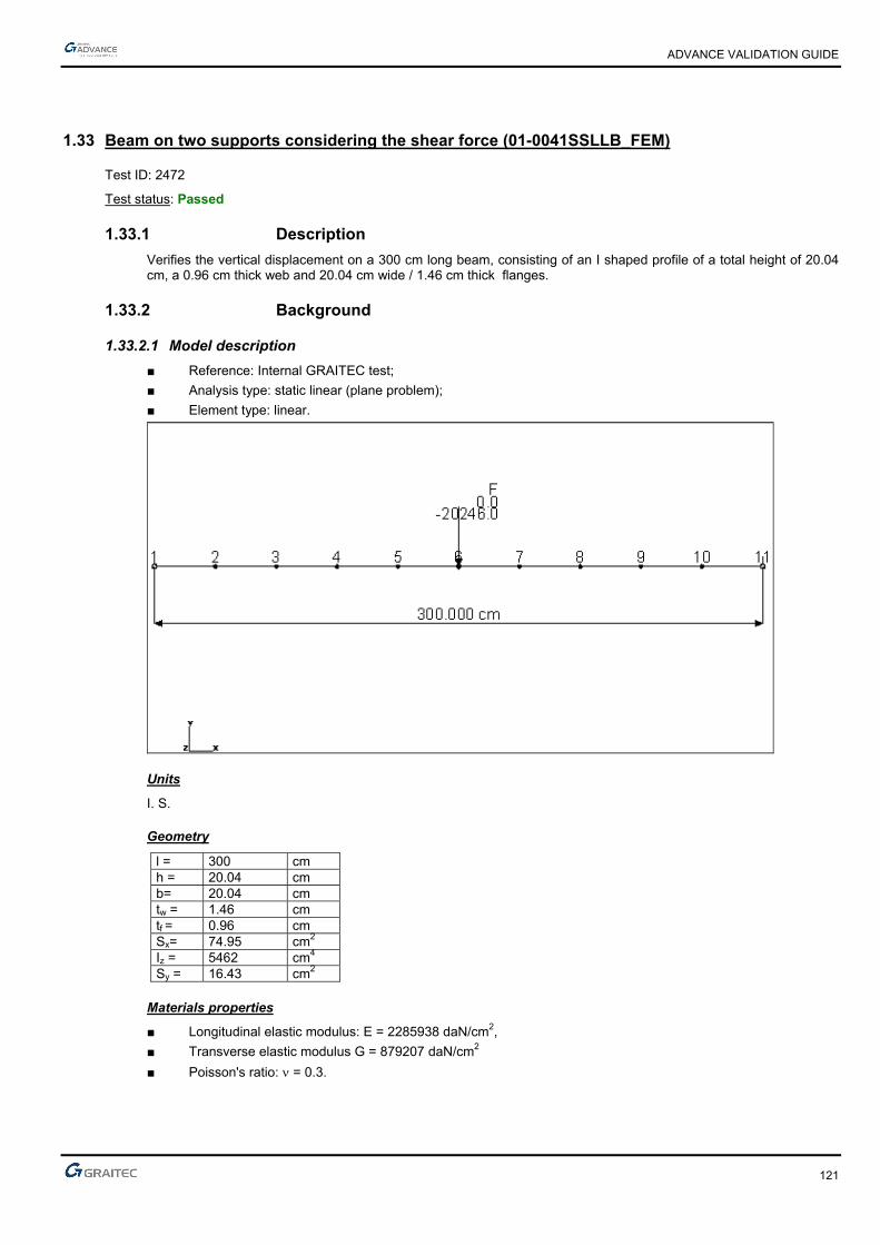
ADVANCE VALIDATION GUIDE
121
1.33 Beam on two supports considering the shear force (01-0041SSLLB_FEM)
Test ID: 2472
Test status: Passed
1.33.1 Description
Verifies the vertical displacement on a 300 cm long beam, consisting of an I shaped profile of a total height of 20.04 cm, a 0.96 cm thick web and 20.04 cm wide / 1.46 cm thick flanges.
1.33.2 Background
1.33.2.1 Model description
■ Reference: Internal GRAITEC test;
■ Analysis type: static linear (plane problem);
■ Element type: linear.
Units
I. S.
Geometry
l = 300 cm h = 20.04 cm b= 20.04 cm tw = 1.46 cm tf = 0.96 cm Sx= 74.95 cm2 Iz = 5462 cm4 Sy = 16.43 cm2
Materials properties
■ Longitudinal elastic modulus: E = 2285938 daN/cm2,
■ Transverse elastic modulus G = 879207 daN/cm2
■ Poisson's ratio: = 0.3.

ADVANCE VALIDATION GUIDE
122
Boundary conditions
■ Outer:
► Simple support on node 11,
► For the modeling, put an hinge at node 1 (instead of a simple support).
■ Inner: None.
Loading
■ External: Vertical punctual load P = -20246 daN at node 6,
■ Internal: None.
1.33.2.2 Vertical displacement of the model in the linear elastic range
Reference solution
The reference displacement is calculated in the middle of the beam, at node 6.
cm 017.1105.0912.0
43.163.012
22859384
30020246
5462228593848
30020246
448
33
6
xx
x
xx
x
GS
Pl
EI
Plv
shear
y
flexion
z
Finite elements modeling
■ Planar element: S beam, imposed mesh,
■ 11 nodes,
■ 10 linear elements.
Deformed shape

ADVANCE VALIDATION GUIDE
123
1.33.2.3 Theoretical results
Solver Result name Result description Reference value
CM2 DZ Vertical displacement at node 6 [cm] -1.017
1.33.3 Calculated results
Result name Result description Value Error
DZ Vertical displacement at node 6 [cm] -1.01722 cm -0.02%

ADVANCE VALIDATION GUIDE
124
1.34 Thin cylinder under a uniform axial load (01-0042SSLSB_FEM)
Test ID: 2473
Test status: Passed
1.34.1 Description
Verifies the stress, the longitudinal deformation and the radial deformation of a cylinder under a uniform axial load.
1.34.2 Background
1.34.2.1 Model description
■ Reference: Structure Calculation Software Validation Guide, test SSLS 07/89;
■ Analysis type: static elastic;
■ Element type: planar.
Thin cylinder under a uniform axial load Scale = 1/19 01-0042SSLSB_FEM
Units
I. S.
Geometry
■ Thickness: h = 0.02 m,
■ Length: L = 4 m,
■ Radius: R = 1 m.
Materials properties
■ Longitudinal elastic modulus: E = 2.1 x 10¹¹ Pa,
■ Poisson's ratio: = 0.3.
ADVANCE VALIDATION GUIDE
125
Boundary conditions
■ Outer:
► Null axial displacement at the left end: vz = 0,
► For the modeling, only a ¼ of the cylinder is considered.
■ Inner: None.
Loading
■ External: Uniform axial load q = 10000 N/m
■ Inner: None.
1.34.2.2 Stress in all points
Reference solution
x axis of the local coordinate system of planar elements is parallel to the cylinders axis.
xx = qh
yy = 0
Finite elements modeling
■ Planar element: shell, imposed mesh,
■ 697 nodes,
■ 640 surface quadrangles.
1.34.2.3 Cylinder deformation at the free end
Reference solution
■ L longitudinal deformation of the cylinder:
L = qLEh
■ R radial deformation of the cylinder:
R = -qREh
Finite elements modeling
■ Planar element: shell, imposed mesh,
■ 697 nodes,
■ 640 surface quadrangles.

ADVANCE VALIDATION GUIDE
126
Deformation shape
Thin cylinder under a uniform axial load Scale = 1/22
Deformation shape
1.34.2.4 Theoretical results
Solver Result name Result description Reference value
CM2 sxx_mid xx stress at all points [Pa] 5 x 10⁵
CM2 syy_mid yy stress at all points [Pa] 0
CM2 DY L longitudinal deformation at the free end [m] 9.52 x 10⁻⁶
CM2 Dz R radial deformation at the free end [m] -7.14 x 10⁻⁷
1.34.3 Calculated results
Result name Result description Value Error
sxx_mid Sigma xx stress at all points [Pa] 500000 Pa 0.00%
syy_mid Sigma yy stress at all points [Pa] 1.05305e-009 Pa 0.00%
DY Delta L longitudinal deformation at the free end [mm] -0.00952381 mm -0.04%
Dz Delta R radial deformation at the free end [mm] 0.000710887 mm -0.44%

ADVANCE VALIDATION GUIDE
127
1.35 Simply supported square plate (01-0036SSLSB_FEM)
Test ID: 2467
Test status: Passed
1.35.1 Description
Verifies the vertical displacement in the center of a simply supported square plate.
1.35.2 Background
1.35.2.1 Model description
■ Reference: Structure Calculation Software Validation Guide, test SSLS 02/89;
■ Analysis type: static linear;
■ Element type: planar.
Simply supported square plate Scale = 1/9 01-0036SSLSB_FEM
Units
I. S.
Geometry
■ Side = 1 m,
■ Thickness h = 0.01m.
Materials properties
■ Longitudinal elastic modulus: E = 2.1 x 10¹¹ Pa,
■ Poisson's ratio: = 0.3,
■ Density: = 7950 kg/m3.
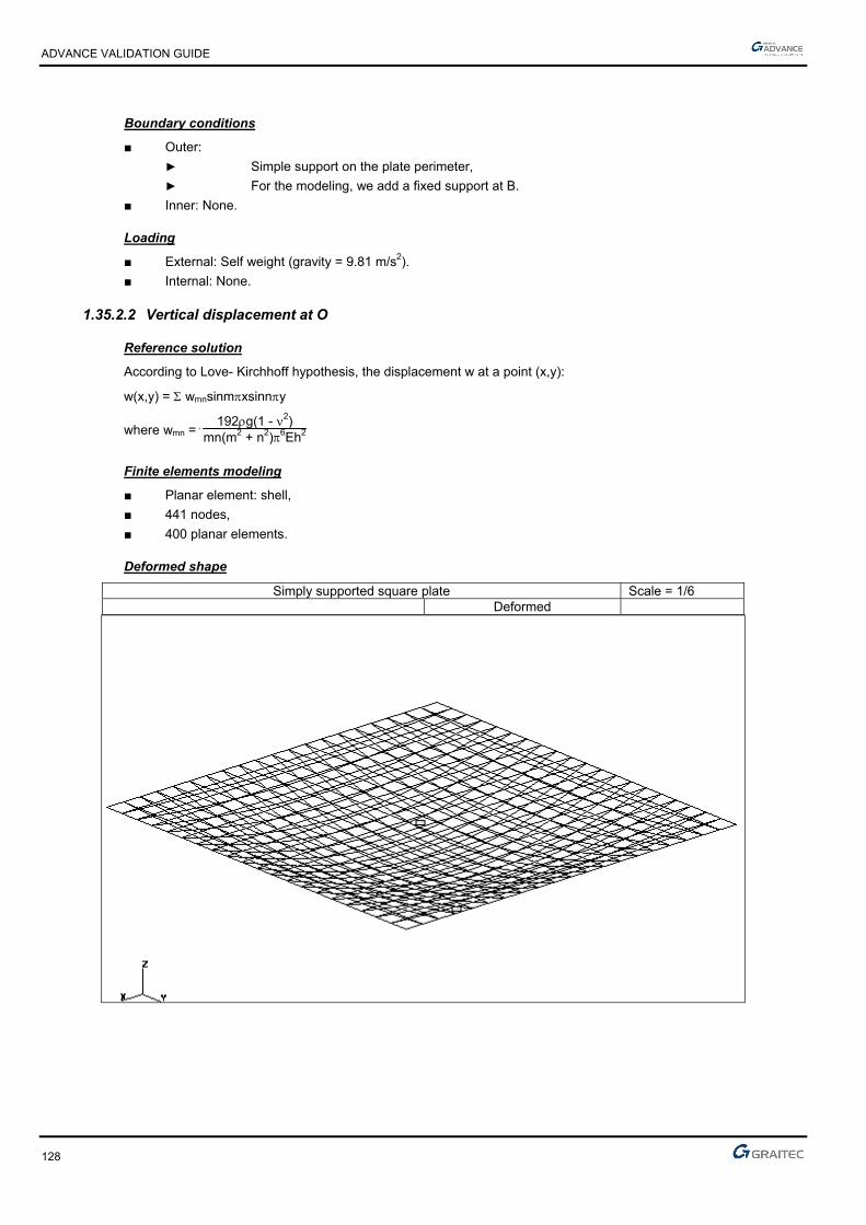
ADVANCE VALIDATION GUIDE
128
Boundary conditions
■ Outer:
► Simple support on the plate perimeter,
► For the modeling, we add a fixed support at B.
■ Inner: None.
Loading
■ External: Self weight (gravity = 9.81 m/s2).
■ Internal: None.
1.35.2.2 Vertical displacement at O
Reference solution
According to Love- Kirchhoff hypothesis, the displacement w at a point (x,y):
w(x,y) = wmnsinmxsinny
where wmn = 192g(1 - 2)
mn(m2 + n2)6Eh2
Finite elements modeling
■ Planar element: shell,
■ 441 nodes,
■ 400 planar elements.
Deformed shape
Simply supported square plate Scale = 1/6 Deformed

ADVANCE VALIDATION GUIDE
129
1.35.2.3 Theoretical results
Solver Result name Result description Reference value
CM2 Dz Vertical displacement in point O [m] -0.158
1.35.3 Calculated results
Result name Result description Value Error
Dz Vertical displacement in point O [µm] -0.164901 µm -4.37%

ADVANCE VALIDATION GUIDE
130
1.36 Stiffen membrane (01-0040SSLSB_FEM)
Test ID: 2471
Test status: Passed
1.36.1 Description
Verifies the horizontal displacement and the stress on a plate (8 x 12 cm) fixed in the middle on 3 supports with a punctual load at its free node.
1.36.2 Background
1.36.2.1 Model description
■ Reference: Klaus-Jürgen Bathe - Finite Element Procedures in Engineering Analysis, Example 5.13;
■ Analysis type: static linear;
■ Element type: planar (membrane).
1;1,
Units
I. S.
Geometry
■ Thickness: e = 0.1 cm,
■ Length: l = 8 cm,
■ Width: B = 12 cm.
Materials properties
■ Longitudinal elastic modulus: E = 30 x 106 N/cm2,
■ Poisson's ratio: = 0.3.
Boundary conditions
■ Outer: Fixed on 3 sides,
■ Inner: None.
Loading
■ External: Uniform load Fx = F = 6000 N at A,
■ Internal: None.
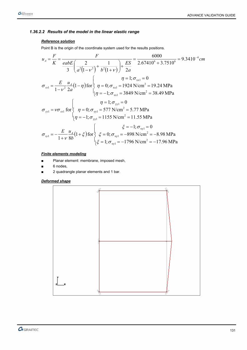
ADVANCE VALIDATION GUIDE
131
1.36.2.2 Results of the model in the linear elastic range
Reference solution
Point B is the origin of the coordinate system used for the results positions.
MPa 96.17N/cm 1796 ;1
MPa 98.8N/cm 898 ;0
0 ;1
for 181
MPa 55.11N/cm 1155 ;1
MPa 77.5N/cm 577 ;0
0 ;1
for
MPa 49.38N/cm 3849 ;1
MPa 24.19N/cm 1924 ;0
0 ;1
for 121
3410.97510.367410.2
6000
21
1
1
2
3
2xy1
2xy1
xy1
1
2yy1
2yy1
yy1
11
2xx1
2xx1
xx1
21
466
222
b
uE
a
uE
cm
a
ES
ba
eabE
F
K
Fu
Axy
xxyy
Axx
A
Finite elements modeling
■ Planar element: membrane, imposed mesh,
■ 6 nodes,
■ 2 quadrangle planar elements and 1 bar.
Deformed shape
ADVANCE VALIDATION GUIDE
132
1.36.2.3 Theoretical results
Solver Result name Result description Reference value
CM2 DX Horizontal displacement Element 1 in A [cm] 9.340000
CM2 sxx_mid xx stress Element 1 in y = 0 cm [MPa] 38.490000
CM2 sxx_mid xx stress Element 1 in y = 6 cm [MPa] 0
CM2 syy_mid yy stress Element 1 in y = 0 cm [MPa] 11.550000
CM2 syy_mid yy stress Element 1 in y = 6 cm [MPa] 0
CM2 sxy_mid xy stress Element 1 in x = 0 cm [MPa] 0
CM2 sxy_mid xy stress Element 1 in x = 4 cm [MPa] -8.980000
CM2 sxy_mid xy stress Element 1 in x = 8 cm [MPa] -17.960000
1.36.3 Calculated results
Result name Result description Value Error
DX Horizontal displacement Element 1 in A [µm] 9.33999 µm 0.00%
sxx_mid Sigma xx stress Element 1 in y = 0 cm [MPa] 38.489 MPa 0.00%
sxx_mid Sigma xx stress Element 1 in y = 6 cm [MPa] 3.63798e-015 MPa 0.00%
syy_mid Sigma yy stress Element 1 in y = 0 cm [MPa] 11.5467 MPa -0.03%
syy_mid Sigma yy stress Element 1 in y = 6 cm [MPa] -9.09495e-016 MPa 0.00%
sxy_mid Sigma xy stress Element 1 in x = 0 cm [MPa] -2.96059e-015 MPa 0.00%
sxy_mid Sigma xy stress Element 1 in x = 4 cm [MPa] -8.98076 MPa -0.01%
sxy_mid Sigma xy stress Element 1 in x = 8 cm [MPa] -17.9615 MPa -0.01%
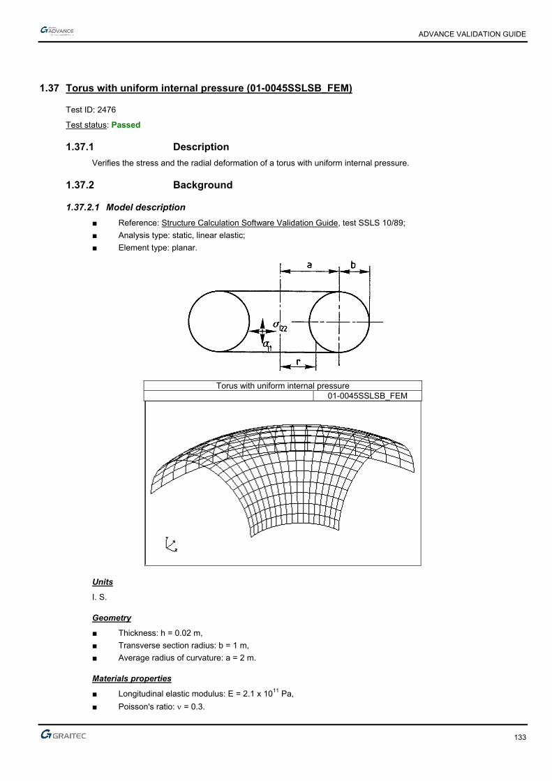
ADVANCE VALIDATION GUIDE
133
1.37 Torus with uniform internal pressure (01-0045SSLSB_FEM)
Test ID: 2476
Test status: Passed
1.37.1 Description
Verifies the stress and the radial deformation of a torus with uniform internal pressure.
1.37.2 Background
1.37.2.1 Model description
■ Reference: Structure Calculation Software Validation Guide, test SSLS 10/89;
■ Analysis type: static, linear elastic;
■ Element type: planar.
Torus with uniform internal pressure 01-0045SSLSB_FEM
Units
I. S.
Geometry
■ Thickness: h = 0.02 m,
■ Transverse section radius: b = 1 m,
■ Average radius of curvature: a = 2 m.
Materials properties
■ Longitudinal elastic modulus: E = 2.1 x 10¹¹ Pa,
■ Poisson's ratio: = 0.3.

ADVANCE VALIDATION GUIDE
134
Boundary conditions
■ Outer: For the modeling, only 1/8 of the cylinder is considered, so the symmetry conditions are imposed to end nodes.
■ Inner: None.
Loading
■ External: Uniform internal pressure p = 10000 Pa
■ Internal: None.
1.37.2.2 Stresses
Reference solution
(See stresses description on the first scheme of the overview)
If a – b r a + b
11 = pb2h
r + ar
22 = pb2h
Finite elements modeling
■ Planar element: shell, imposed mesh,
■ 361 nodes,
■ 324 surface quadrangles.
1.37.2.3 Cylinder deformation
Reference solution
■ R radial deformation of the torus:
R = pb
2Eh (r - (r + a))
Finite elements modeling
■ Planar element: shell, imposed mesh,
■ 361 nodes,
■ 324 surface quadrangles.
ADVANCE VALIDATION GUIDE
135
1.37.2.4 Theoretical results
Solver Result name Result description Reference value
CM2 syy_mid 11 stresses for r = a - b [Pa] 7.5 x 10⁵
CM2 syy_mid 11 stresses for r = a + b [Pa] 4.17 x 10⁵
CM2 sxx_mid 22 stress for all r [Pa] 2.50 x 10⁵
CM2 Dz L radial deformations of the torus for r = a - b [m] 1.19 x 10⁻⁷
CM2 Dz L radial deformations of the torus for r = a + b [m] 1.79 x 10⁻⁶
1.37.3 Calculated results
Result name Result description Value Error
syy_mid Sigma 11 stresses for r = a - b [Pa] 742770 Pa -0.96%
syy_mid Sigma 11 stresses for r = a + b [Pa] 415404 Pa -0.38%
sxx_mid Sigma 22 stress for all r [Pa] 250331 Pa 0.13%
Dz Delta L radial deformations of the torus for r = a - b [mm] -0.000117352 mm 1.38%
Dz Delta L radial deformations of the torus for r = a + b [mm] 0.00180274 mm 0.71%

ADVANCE VALIDATION GUIDE
136
1.38 Spherical shell under internal pressure (01-0046SSLSB_FEM)
Test ID: 2477
Test status: Passed
1.38.1 Description
A spherical shell is subjected to a uniform internal pressure. The stress and the radial deformation are verified.
1.38.2 Background
1.38.2.1 Model description
■ Reference: Structure Calculation Software Validation Guide, test SSLS 14/89;
■ Analysis type: static, linear elastic;
■ Element type: planar.
Spherical shell under internal pressure 01-0046SSLSB_FEM
Units
I. S.
Geometry
■ Thickness: h = 0.02 m,
■ Radius: R2 = 1 m,
■ = 90° (hemisphere).
ADVANCE VALIDATION GUIDE
137
Materials properties
■ Longitudinal elastic modulus: E = 2.1 x 10¹¹ Pa,
■ Poisson's ratio: = 0.3.
Boundary conditions
■ Outer:
Simple support (null displacement along vertical displacement) on the shell perimeter.
For modeling, we consider only half of the hemisphere, so we impose symmetry conditions (DOF restrains placed in the vertical plane xy in translation along z and in rotation along x and y). In addition, the node at the top of the shell is restrained in translation along x to assure the stability of the structure during calculation).
■ Inner: None.
Loading
■ External: Uniform internal pressure p = 10000 Pa
■ Internal: None.
1.38.2.2 Stresses
Reference solution
(See stresses description on the first scheme of the overview)
If 0° 90°
11 = 22 = pR2
2
2h
Finite elements modeling
■ Planar element: shell, imposed mesh,
■ 343 nodes,
■ 324 planar elements.
1.38.2.3 Cylinder deformation
Reference solution
■ R radial deformation of the calotte:
R = pR22 (1 - ) sin
2Eh
Finite elements modeling
■ Planar element: shell, imposed mesh,
■ 343 nodes,
■ 324 planar elements.
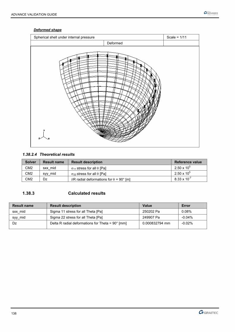
ADVANCE VALIDATION GUIDE
138
Deformed shape
Spherical shell under internal pressure Scale = 1/11
Deformed
1.38.2.4 Theoretical results
Solver Result name Result description Reference value
CM2 sxx_mid 11 stress for all [Pa] 2.50 x 10⁵
CM2 syy_mid 22 stress for all [Pa] 2.50 x 10⁵
CM2 Dz R radial deformations for = 90° [m] 8.33 x 10⁻⁷
1.38.3 Calculated results
Result name Result description Value Error
sxx_mid Sigma 11 stress for all Theta [Pa] 250202 Pa 0.08%
syy_mid Sigma 22 stress for all Theta [Pa] 249907 Pa -0.04%
Dz Delta R radial deformations for Theta = 90° [mm] 0.000832794 mm -0.02%

ADVANCE VALIDATION GUIDE
139
1.39 Thin cylinder under its self weight (01-0044SSLSB_MEF)
Test ID: 2475
Test status: Passed
1.39.1 Description
Verifies the stress, the longitudinal deformation and the radial deformation of a thin cylinder subjected to its self weight only.
1.39.2 Background
1.39.2.1 Model description
■ Reference: Structure Calculation Software Validation Guide, test SSLS 09/89;
■ Analysis type: static, linear elastic;
■ Element type: planar.
A cylinder of R radius and L length subject of self weight only.
Thin cylinder under its self weight Scale = 1/24 01-0044SSLSB_FEM
Units
I. S.
Geometry
■ Thickness: h = 0.02 m,
■ Length: L = 4 m,
■ Radius: R = 1 m.
Materials properties
■ Longitudinal elastic modulus: E = 2.1 x 10¹¹ Pa,
■ Poisson's ratio: = 0.3,
■ Density: = 7.85 x 10⁴ N/m3.
ADVANCE VALIDATION GUIDE
140
Boundary conditions
■ Outer:
► Null axial displacement at z = 0,
► For the modeling, we consider only a quarter of the cylinder, so we impose the symmetry conditions on the nodes that are parallel with the cylinder’s axis.
■ Inner: None.
Loading
■ External: Cylinder self weight,
■ Internal: None.
1.39.2.2 Stresses
Reference solution
x axis of the local coordinate system of planar elements is parallel to the cylinders axis.
xx = z
yy = 0
Finite elements modeling
■ Planar element: shell, imposed mesh,
■ 697 nodes,
■ 640 surface quadrangles.
1.39.2.3 Cylinder deformation
Reference solution
■ L longitudinal deformation of the cylinder:
L = z2
2E
■ R radial deformation of the cylinder:
R = -Rz
E
1.39.2.4 Theoretical results
Solver Result name Result description Reference value
CM2 sxx_mid xx stress for z = L [Pa] -314000.000000
CM2 DY L longitudinal deformation for z = L [mm] 0.002990
CM2 Dz R radial deformation for z = L[mm] -0.000440
* To obtain this result, you must generate a calculation note “Planar elements stresses by load case in neutral fiber" with results on center.
1.39.3 Calculated results
Result name Result description Value Error
sxx_mid Sigma xx stress for z = L [Pa] -309143 Pa 1.55%
DY Delta L longitudinal deformation for z = L [mm] 0.00298922 mm -0.03%
Dz Delta R radial deformation for z = L [mm] -0.000443587 mm -0.82%
ADVANCE VALIDATION GUIDE
141
1.40 Beam on elastic soil, hinged ends (01-0034SSLLB_FEM)
Test ID: 2466
Test status: Passed
1.40.1 Description
A beam under a punctual load, a distributed load and two torques lays on a soil of constant linear stiffness. The rotation around z-axis, the vertical reaction, the vertical displacement and the bending moment are verified in several points.
1.40.2 Background
1.40.2.1 Model description
■ Reference: Structure Calculation Software Validation Guide, test SSLL 16/89;
■ Analysis type: static linear (plane problem);
■ Element type: linear.
Beam on elastic soil, hinged ends Scale = 1/27 01-0034SSLLB_FEM
Units
I. S.
Geometry
■ L = ( 10 )/2,
■ I = 10-4 m4.

ADVANCE VALIDATION GUIDE
142
Materials properties
Longitudinal elastic modulus: E = 2.1 x 10¹¹ Pa.
Boundary conditions
■ Outer:
► Free A and B ends,
► Soil with a constant linear stiffness ky = K = 840000 N/m2.
■ Inner: None.
Loading
■ External:
► Punctual force at D: Fy = F = - 10000 N,
► Uniformly distributed force from A to B: fy = p = - 5000 N/m,
► Torque at A: Cz = -C = -15000 Nm,
► Torque at B: Cz = C = 15000 Nm.
■ Internal: None.
1.40.2.2 Displacement and support reaction at A
Reference solution
= 4
K/(4EI)
= L/2
= ch(2) + cos(2)
■ Vertical support reaction:
VA = -p(sh(2) + sin(2)) - 2Fch()cos() + 22C(sh(2) - sin(2)) x 1
2
■ Rotation about z-axis:
A = p(sh(2) – sin(2)) + 2Fsh()sin() - 22C(sh(2) + sin(2)) x 1
(K/)
Finite elements modeling
■ Linear element: beam,
■ 50 nodes,
■ 49 linear elements.

ADVANCE VALIDATION GUIDE
143
Deformed shape
Beam on elastic soil, hinged ends Scale = 1/20
Deformed
1.40.2.3 Displacement and bending moment at D
Reference solution
■ Vertical displacement:
vD = 2p( - 2ch()cos()) + F(sh(2) – sin(2)) - 82Csh()sin() x 1
2K
■ Bending moment:
MD = 4psh()sin() + F(sh(2) + sin(2)) - 82Cch()cos() x 1
42
Finite elements modeling
■ Linear element: beam,
■ 50 nodes,
■ 49 linear elements.
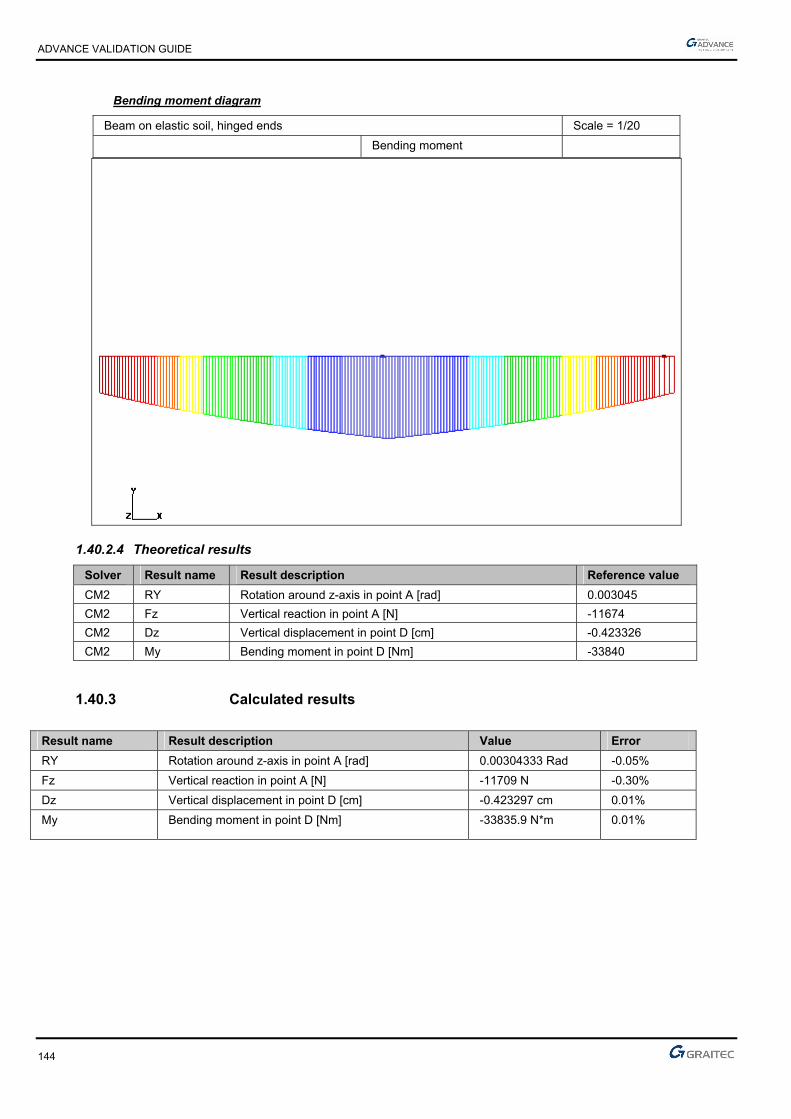
ADVANCE VALIDATION GUIDE
144
Bending moment diagram
Beam on elastic soil, hinged ends Scale = 1/20
Bending moment
1.40.2.4 Theoretical results
Solver Result name Result description Reference value
CM2 RY Rotation around z-axis in point A [rad] 0.003045
CM2 Fz Vertical reaction in point A [N] -11674
CM2 Dz Vertical displacement in point D [cm] -0.423326
CM2 My Bending moment in point D [Nm] -33840
1.40.3 Calculated results
Result name Result description Value Error
RY Rotation around z-axis in point A [rad] 0.00304333 Rad -0.05%
Fz Vertical reaction in point A [N] -11709 N -0.30%
Dz Vertical displacement in point D [cm] -0.423297 cm 0.01%
My Bending moment in point D [Nm] -33835.9 N*m 0.01%

ADVANCE VALIDATION GUIDE
145
1.41 Square plate under planar stresses (01-0039SSLSB_FEM)
Test ID: 2470
Test status: Passed
1.41.1 Description
Verifies the vertical displacement and the stresses on a square plate of 2 x 2 m, fixed on 3 sides with a uniform surface load on its surface.
1.41.2 Background
1.41.2.1 Model description
■ Reference: Internal GRAITEC test;
■ Analysis type: static linear;
■ Element type: planar (membrane).
Square plate under planar stresses Scale = 1/19 Modeling
1;1,
Units
I. S.
Geometry
■ Thickness: e = 1 m,
■ 4 square elements of side h = 1 m.
Materials properties
■ Longitudinal elastic modulus: E = 2.1 x 10¹¹ Pa,
■ Poisson's ratio: = 0.3.

ADVANCE VALIDATION GUIDE
146
Boundary conditions
■ Outer: Fixed on 3 sides,
■ Inner: None.
Loading
■ External: Uniform load p = -1. 108 N/ml on the upper surface,
■ Internal: None.
1.41.2.2 Displacement of the model in the linear elastic range
Reference solution
The reference displacements are calculated on nodes 7 and 9.
v9 = -6ph(3 + )(1 - 2)
E(8(3 - )2 - (3 + )2) = -0.1809 x 10⁻³ m,
v7 = 4(3 - )3 + v9 = -0.592 x 10⁻³ m,
For element 1.4:
(For the stresses calculated above, the abscissa point (x = 0; y = 0) corresponds to node 8.)
yy = E
1 - 2 (v9 - v7)
2h (1 + ) for
xx = yy for
xy = E
1 + (v9 + v7) + (v9 - v7)
4h (1 + ) for
Finite elements modeling
■ Planar element: membrane, imposed mesh,
■ 9 nodes,
■ 4 surface quadrangles.
= -1 ; xx = 0 = 0 ; xx = -14.23 MPa = 1 ; xx = -28.46 MPa
= -1 ; = 0 ; xy = -47.82 MPa = 0 ; = 0 ; xy = -31.21 MPa = 1 ; = 0 ; xy = -14.61 MPa
= -1 ; yy = 0 = 0 ; yy = -47.44 MPa = 1 ; yy = -94.88 MPa
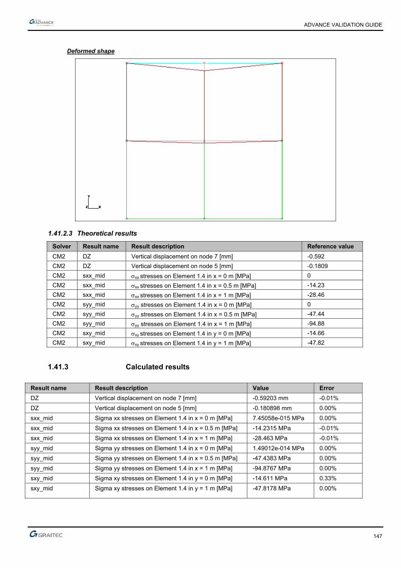
ADVANCE VALIDATION GUIDE
147
Deformed shape
1.41.2.3 Theoretical results
Solver Result name Result description Reference value
CM2 DZ Vertical displacement on node 7 [mm] -0.592
CM2 DZ Vertical displacement on node 5 [mm] -0.1809
CM2 sxx_mid xx stresses on Element 1.4 in x = 0 m [MPa] 0
CM2 sxx_mid xx stresses on Element 1.4 in x = 0.5 m [MPa] -14.23
CM2 sxx_mid xx stresses on Element 1.4 in x = 1 m [MPa] -28.46
CM2 syy_mid yy stresses on Element 1.4 in x = 0 m [MPa] 0
CM2 syy_mid yy stresses on Element 1.4 in x = 0.5 m [MPa] -47.44
CM2 syy_mid yy stresses on Element 1.4 in x = 1 m [MPa] -94.88
CM2 sxy_mid xy stresses on Element 1.4 in y = 0 m [MPa] -14.66
CM2 sxy_mid xy stresses on Element 1.4 in y = 1 m [MPa] -47.82
1.41.3 Calculated results
Result name Result description Value Error
DZ Vertical displacement on node 7 [mm] -0.59203 mm -0.01%
DZ Vertical displacement on node 5 [mm] -0.180898 mm 0.00%
sxx_mid Sigma xx stresses on Element 1.4 in x = 0 m [MPa] 7.45058e-015 MPa 0.00%
sxx_mid Sigma xx stresses on Element 1.4 in x = 0.5 m [MPa] -14.2315 MPa -0.01%
sxx_mid Sigma xx stresses on Element 1.4 in x = 1 m [MPa] -28.463 MPa -0.01%
syy_mid Sigma yy stresses on Element 1.4 in x = 0 m [MPa] 1.49012e-014 MPa 0.00%
syy_mid Sigma yy stresses on Element 1.4 in x = 0.5 m [MPa] -47.4383 MPa 0.00%
syy_mid Sigma yy stresses on Element 1.4 in x = 1 m [MPa] -94.8767 MPa 0.00%
sxy_mid Sigma xy stresses on Element 1.4 in y = 0 m [MPa] -14.611 MPa 0.33%
sxy_mid Sigma xy stresses on Element 1.4 in y = 1 m [MPa] -47.8178 MPa 0.00%

ADVANCE VALIDATION GUIDE
148
1.42 Thin cylinder under a hydrostatic pressure (01-0043SSLSB_FEM)
Test ID: 2474
Test status: Passed
1.42.1 Description
Verifies the stress, the longitudinal deformation and the radial deformation of a thin cylinder under a hydrostatic pressure.
1.42.2 Background
1.42.2.1 Model description
■ Reference: Structure Calculation Software Validation Guide, test SSLS 08/89;
■ Analysis type: static, linear elastic;
■ Element type: planar.
Thin cylinder under a hydrostatic pressure Scale = 1/25 01-0043SSLSB_FEM
Units
I. S.
Geometry
■ Thickness: h = 0.02 m,
■ Length: L = 4 m,
■ Radius: R = 1 m.
Materials properties
■ Longitudinal elastic modulus: E = 2.1 x 10¹¹ Pa,
■ Poisson's ratio: = 0.3.
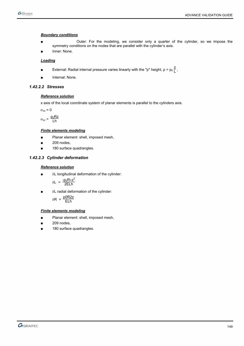
ADVANCE VALIDATION GUIDE
149
Boundary conditions
■ Outer: For the modeling, we consider only a quarter of the cylinder, so we impose the symmetry conditions on the nodes that are parallel with the cylinder’s axis.
■ Inner: None.
Loading
■ External: Radial internal pressure varies linearly with the "p" height, p = p0 zL ,
■ Internal: None.
1.42.2.2 Stresses
Reference solution
x axis of the local coordinate system of planar elements is parallel to the cylinders axis.
xx = 0
yy = p0RzLh
Finite elements modeling
■ Planar element: shell, imposed mesh,
■ 209 nodes,
■ 180 surface quadrangles.
1.42.2.3 Cylinder deformation
Reference solution
■ L longitudinal deformation of the cylinder:
L = -p0Rz2
2ELh
■ L radial deformation of the cylinder:
R = p0R2zELh
Finite elements modeling
■ Planar element: shell, imposed mesh,
■ 209 nodes,
■ 180 surface quadrangles.
ADVANCE VALIDATION GUIDE
150
Deformation shape
Thin cylinder under a hydrostatic pressure
Deformed
1.42.2.4 Theoretical results
Solver Result name Result description Reference value
CM2 syy_mid yy stress in z = L/2 [Pa] 500000.000000
CM2 DY L longitudinal deformation of the cylinder at the inferior extremity [mm]
-0.002860
CM2 Dz L radial deformation of the cylinder in z = L/2 [mm] 0.002380
1.42.3 Calculated results
Result name Result description Value Error
syy_mid Sigma yy stress in z = L/2 [Pa] 504489 Pa 0.90%
DY Delta L longitudinal deformation of the cylinder at the inferior extremity [mm]
-0.00285442 mm 0.20%
Dz Delta L radial deformation of the cylinder in z = L/2 [mm] 0.00238372 mm 0.16%

ADVANCE VALIDATION GUIDE
151
1.43 Spherical dome under a uniform external pressure (01-0050SSLSB_FEM)
Test ID: 2480
Test status: Passed
1.43.1 Description
A spherical dome of radius (a) is subjected to a uniform external pressure. The horizontal displacement and the external meridian stresses are verified.
1.43.2 Background
1.43.2.1 Model description
■ Reference: Structure Calculation Software Validation Guide, test SSLS 22/89;
■ Analysis type: static, linear elastic;
■ Element type: planar.
Spherical dome under a uniform external pressure 01-0050SSLSB_FEM
Units
I. S.

ADVANCE VALIDATION GUIDE
152
Geometry
■ Radius: a = 2.54 m,
■ Thickness: h = 0.0127 m,
■ Angle: = 75°.
Materials properties
■ Longitudinal elastic modulus: E = 6.897 x 10¹⁰ Pa,
■ Poisson's ratio: = 0.2.
Boundary conditions
■ Outer: Fixed on the dome perimeter,
■ Inner: None.
Loading
■ External: Uniform pressure p = 0.6897 x 10⁶ Pa,
■ Internal: None.
1.43.2.2 Horizontal displacement and exterior meridian stress
Reference solution
The reference solution is determined by averaging the results of several calculation software with implemented finite elements method. 2% uncertainty about the reference solution.
Finite elements modeling
■ Planar element: shell, imposed mesh,
■ 401 nodes,
■ 400 planar elements.
Deformed shape

ADVANCE VALIDATION GUIDE
153
1.43.2.3 Theoretical results
Solver Result name Result description Reference value
CM2 DX Horizontal displacements in = 15° 1.73 x 10⁻³
CM2 DX Horizontal displacements in = 45° -1.02 x 10⁻³
CM2 syy_mid yy external meridian stresses in = 15° -74
CM2 sxx_mid XX external meridian stresses in = 45° -68
1.43.3 Calculated results
Result name Result description Value Error
DX Horizontal displacements in Psi = 15° [mm] 1.73064 mm 0.04%
DX Horizontal displacements in Psi = 45° [mm] -1.01367 mm 0.62%
syy_mid Sigma yy external meridian stresses in Psi = 15° [MPa] -72.2609 MPa 2.35%
sxx_mid Sigma XX external meridian stresses in Psi = 45° [MPa] -68.9909 MPa -1.46%

ADVANCE VALIDATION GUIDE
154
1.44 Simply supported square plate under a uniform load (01-0051SSLSB_FEM)
Test ID: 2481
Test status: Passed
1.44.1 Description
A square plate simply supported is subjected to a uniform load. The vertical displacement and the bending moments at the plate center are verified.
1.44.2 Background
1.44.2.1 Model description
■ Reference: Structure Calculation Software Validation Guide, test SSLS 24/89;
■ Analysis type: static, linear elastic;
■ Element type: planar.
Simply supported square plate under a uniform load Scale = 1/9 01-0051SSLSB_FEM
Units
I. S.
Geometry
■ Side: a =b = 1 m,
■ Thickness: h = 0.01 m,
Materials properties
■ Longitudinal elastic modulus: E = 1.0 x 10⁷ Pa,
■ Poisson's ratio: = 0.3.
ADVANCE VALIDATION GUIDE
155
Boundary conditions
■ Outer: Simple support on the plate perimeter (null displacement along z-axis),
■ Inner: None
Loading
■ External: Normal pressure of plate p = pZ = -1.0 Pa,
■ Internal: None.
1.44.2.2 Vertical displacement and bending moment at the center of the plate
Reference solution
Love-Kirchhoff thin plates theory.
Finite elements modeling
■ Planar element: plate, imposed mesh,
■ 361 nodes,
■ 324 planar elements.
1.44.2.3 Theoretical result
Solver Result name Result description Reference value
CM2 DZ Vertical displacement at plate center [m] -4.43 x 10⁻³
CM2 Mxx MX bending moment at plate center [Nm] 0.0479
CM2 Myy MY bending moment at plate center [Nm] 0.0479
1.44.3 Calculated results
Result name Result description Value Error
DZ Vertical displacement at plate center [m] -0.00435847 m 1.61%
Mxx Mx bending moment at plate center [Nm] 0.0471381 N*m -1.59%
Myy My bending moment at plate center [Nm] 0.0471381 N*m -1.59%
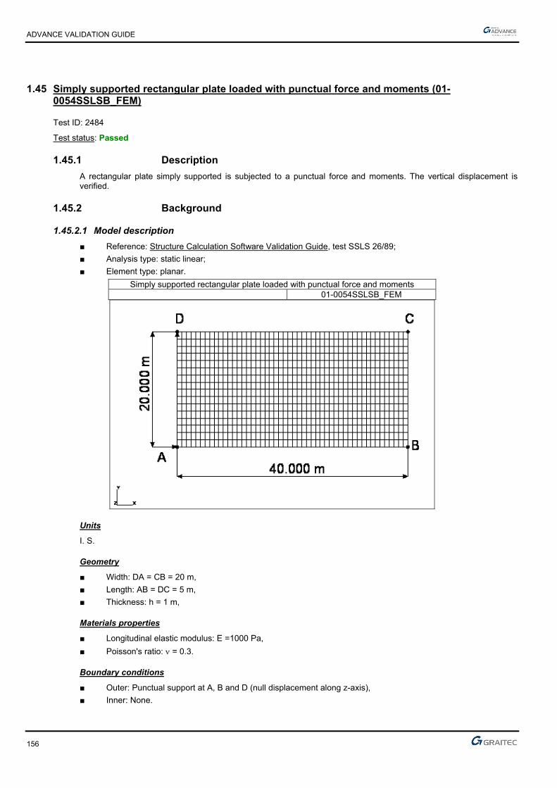
ADVANCE VALIDATION GUIDE
156
1.45 Simply supported rectangular plate loaded with punctual force and moments (01-0054SSLSB_FEM)
Test ID: 2484
Test status: Passed
1.45.1 Description
A rectangular plate simply supported is subjected to a punctual force and moments. The vertical displacement is verified.
1.45.2 Background
1.45.2.1 Model description
■ Reference: Structure Calculation Software Validation Guide, test SSLS 26/89;
■ Analysis type: static linear;
■ Element type: planar.
Simply supported rectangular plate loaded with punctual force and moments 01-0054SSLSB_FEM
Units
I. S.
Geometry
■ Width: DA = CB = 20 m,
■ Length: AB = DC = 5 m,
■ Thickness: h = 1 m,
Materials properties
■ Longitudinal elastic modulus: E =1000 Pa,
■ Poisson's ratio: = 0.3.
Boundary conditions
■ Outer: Punctual support at A, B and D (null displacement along z-axis),
■ Inner: None.

ADVANCE VALIDATION GUIDE
157
Loading
■ External:
► In A: MX = 20 Nm, MY = -10 Nm,
► In B: MX = 20 Nm, MY = 10 Nm,
► In C: FZ = -2 N, MX = -20 Nm, MY = 10 Nm,
► In D: MX = -20 Nm, MY = -10 Nm,
■ Internal: None.
1.45.2.2 Vertical displacement at C
Reference solution
Love-Kirchhoff thin plates theory.
Finite elements modeling
■ Planar element: plate, imposed mesh,
■ 867 nodes,
■ 800 surface quadrangles.
Deformed shape
Simply supported rectangular plate loaded with punctual force and moments Deformed
1.45.2.3 Theoretical results
Solver Result name Result description Reference value
CM2 Dz Vertical displacement in point C [m] -12.480
1.45.3 Calculated results
Result name Result description Value Error
Dz Vertical displacement in point C [m] -12.6677 m -1.50%

ADVANCE VALIDATION GUIDE
158
1.46 Shear plate perpendicular to the medium surface (01-0055SSLSB_FEM)
Test ID: 2485
Test status: Passed
1.46.1 Description
Verifies the vertical displacement of a rectangular shear plate fixed at one end, loaded with two forces.
1.46.2 Background
1.46.2.1 Model description
■ Reference: Structure Calculation Software Validation Guide, test SSLS 27/89;
■ Analysis type: static;
■ Element type: planar.
Shear plate Scale = 1/50 01-0055SSLSB_FEM
Units
I. S.
Geometry
■ Length: L = 12 m,
■ Width: l = 1 m,
■ Thickness: h = 0.05 m,
Materials properties
■ Longitudinal elastic modulus: E = 1.0 x 10⁷ Pa,
■ Poisson's ratio: = 0.25.
Boundary conditions
■ Outer: Fixed AD edge,
■ Inner: None.

ADVANCE VALIDATION GUIDE
159
Loading
■ External:
► At B: Fz = -1.0 N,
► At C: FZ = 1.0 N,
■ Internal: None.
1.46.2.2 Vertical displacement at C
Reference solution
Analytical solution.
Finite elements modeling
■ Planar element: plate, imposed mesh,
■ 497 nodes,
■ 420 surface quadrangles.
Deformed shape
Shear plate Scale = 1/35 Deformed
1.46.2.3 Theoretical results
Solver Result name Result description Reference value
CM2 Dz Vertical displacement in point C [m] 35.37 x 10⁻³
1.46.3 Calculated results
Result name Result description Value Error
Dz Vertical displacement in point C [m] 35.6655 mm 0.84%
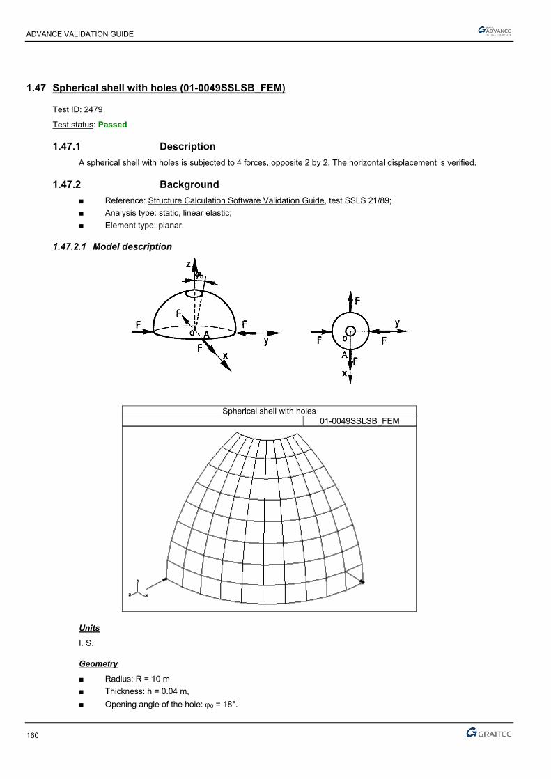
ADVANCE VALIDATION GUIDE
160
1.47 Spherical shell with holes (01-0049SSLSB_FEM)
Test ID: 2479
Test status: Passed
1.47.1 Description
A spherical shell with holes is subjected to 4 forces, opposite 2 by 2. The horizontal displacement is verified.
1.47.2 Background
■ Reference: Structure Calculation Software Validation Guide, test SSLS 21/89;
■ Analysis type: static, linear elastic;
■ Element type: planar.
1.47.2.1 Model description
Spherical shell with holes 01-0049SSLSB_FEM
Units
I. S.
Geometry
■ Radius: R = 10 m
■ Thickness: h = 0.04 m,
■ Opening angle of the hole: 0 = 18°.

ADVANCE VALIDATION GUIDE
161
Materials properties
■ Longitudinal elastic modulus: E = 6.285 x 10⁷ Pa,
■ Poisson's ratio: = 0.3.
Boundary conditions
■ Outer: For modeling, we consider only a quarter of the shell, so we impose symmetry conditions (nodes in the vertical yz plane are restrained in translation along x and in rotation along y and z. Nodes on the vertical xy plane are restrained in translation along z and in rotation along x and y),
■ Inner: None.
Loading
■ External: Punctual loads F = 1 N, according to the diagram,
■ Internal: None.
1.47.2.2 Horizontal displacement at point A
Reference solution
The reference solution is determined by averaging the results of several calculation software with implemented finite elements method. 2% uncertainty about the reference solution.
Finite elements modeling
■ Planar element: shell, imposed mesh,
■ 99 nodes,
■ 80 surface quadrangles.
Deformed shape
Spherical shell with holes Scale = 1/79 Deformed

ADVANCE VALIDATION GUIDE
162
1.47.2.3 Theoretical background
Solver Result name Result description Reference value
CM2 DX Horizontal displacement at point A(R,0,0) [mm] 94.0
1.47.3 Calculated results
Result name Result description Value Error
DX Horizontal displacement at point A(R,0,0) [mm] 92.6205 mm -1.47%

ADVANCE VALIDATION GUIDE
163
1.48 Simply supported rectangular plate under a uniform load (01-0053SSLSB_FEM)
Test ID: 2483
Test status: Passed
1.48.1 Description
A rectangular plate simply supported is subjected to a uniform load. The vertical displacement and the bending moments at the plate center are verified.
1.48.2 Background
1.48.2.1 Model description
■ Reference: Structure Calculation Software Validation Guide, test SSLS 24/89;
■ Analysis type: static, linear elastic;
■ Element type: planar.
Simply supported rectangular plate under a uniform load Scale = 1/25 01-0053SSLSB_FEM
Units
I. S.
Geometry
■ Width: a = 1 m,
■ Length: b = 5 m,
■ Thickness: h = 0.01 m,
Materials properties
■ Longitudinal elastic modulus: E = 1.0 x 10⁷ Pa,
■ Poisson's ratio: = 0.3.
Boundary conditions
■ Outer: Simple support on the plate perimeter (null displacement along z-axis),
■ Inner: None.

ADVANCE VALIDATION GUIDE
164
Loading
■ External: Normal pressure of plate p = pZ = -1.0 Pa,
■ Internal: None.
1.48.2.2 Vertical displacement and bending moment at the center of the plate
Reference solution
Love-Kirchhoff thin plates theory.
Finite elements modeling
■ Planar element: plate, imposed mesh,
■ 793 nodes,
■ 720 surface quadrangles.
1.48.2.3 Theoretical results
Solver Result name Result description Reference value
CM2 DZ Vertical displacement at plate center [m] 1.416 x 10⁻²
CM2 Mxx MX bending moment at plate center [Nm] 0.1246
CM2 Myy MY bending moment at plate center [Nm] 0.0375
1.48.3 Calculated results
Result name Result description Value Error
DZ Vertical displacement at plate center [cm] -1.40141 cm 1.03%
Mxx Mx bending moment at plate center [Nm] -0.124082 N*m 0.42%
Myy My bending moment at plate center [Nm] -0.0375624 N*m -0.17%
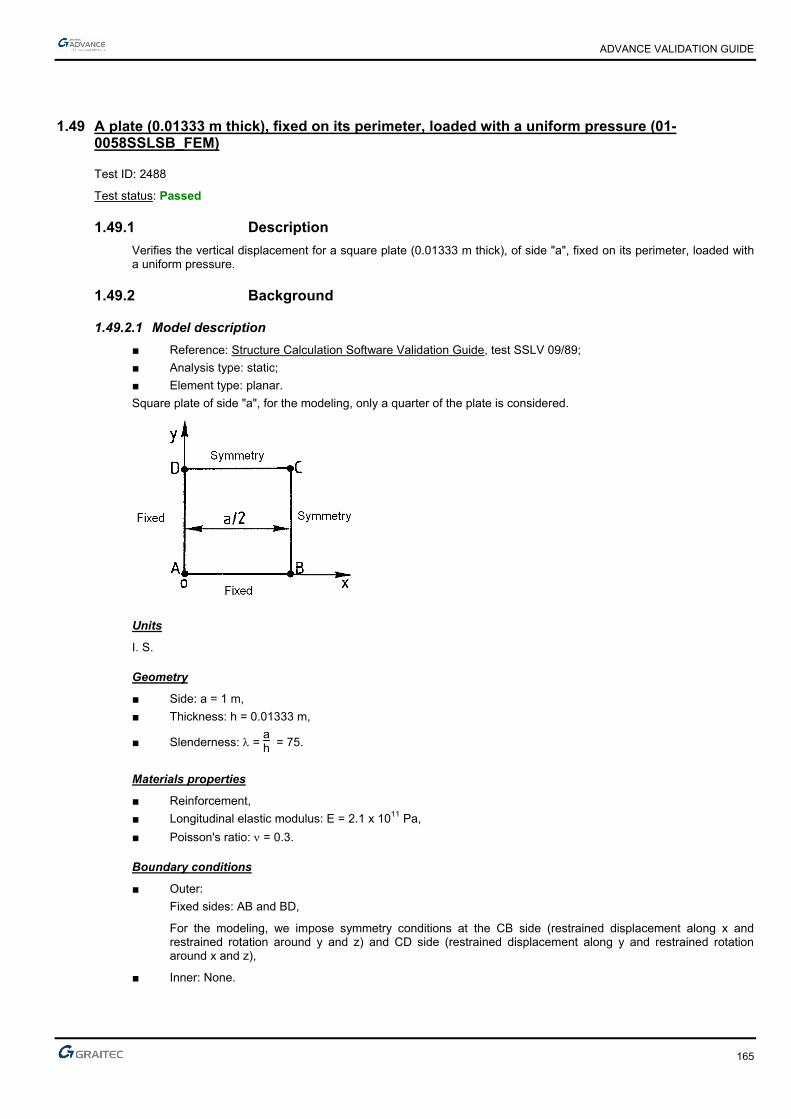
ADVANCE VALIDATION GUIDE
165
1.49 A plate (0.01333 m thick), fixed on its perimeter, loaded with a uniform pressure (01-0058SSLSB_FEM)
Test ID: 2488
Test status: Passed
1.49.1 Description
Verifies the vertical displacement for a square plate (0.01333 m thick), of side "a", fixed on its perimeter, loaded with a uniform pressure.
1.49.2 Background
1.49.2.1 Model description
■ Reference: Structure Calculation Software Validation Guide, test SSLV 09/89;
■ Analysis type: static;
■ Element type: planar.
Square plate of side "a", for the modeling, only a quarter of the plate is considered.
Units
I. S.
Geometry
■ Side: a = 1 m,
■ Thickness: h = 0.01333 m,
■ Slenderness: = ah = 75.
Materials properties
■ Reinforcement,
■ Longitudinal elastic modulus: E = 2.1 x 10¹¹ Pa,
■ Poisson's ratio: = 0.3.
Boundary conditions
■ Outer:
Fixed sides: AB and BD,
For the modeling, we impose symmetry conditions at the CB side (restrained displacement along x and restrained rotation around y and z) and CD side (restrained displacement along y and restrained rotation around x and z),
■ Inner: None.
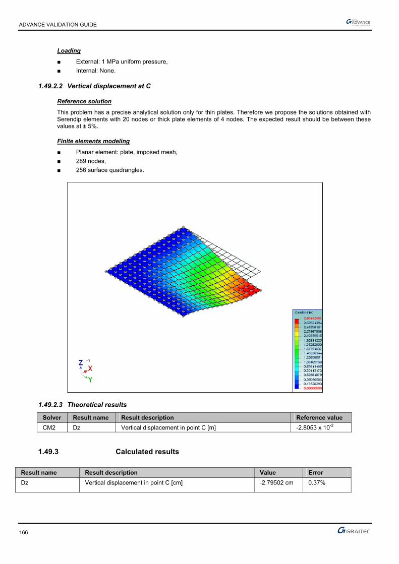
ADVANCE VALIDATION GUIDE
166
Loading
■ External: 1 MPa uniform pressure,
■ Internal: None.
1.49.2.2 Vertical displacement at C
Reference solution
This problem has a precise analytical solution only for thin plates. Therefore we propose the solutions obtained with Serendip elements with 20 nodes or thick plate elements of 4 nodes. The expected result should be between these values at ± 5%.
Finite elements modeling
■ Planar element: plate, imposed mesh,
■ 289 nodes,
■ 256 surface quadrangles.
1.49.2.3 Theoretical results
Solver Result name Result description Reference value
CM2 Dz Vertical displacement in point C [m] -2.8053 x 10⁻²
1.49.3 Calculated results
Result name Result description Value Error
Dz Vertical displacement in point C [cm] -2.79502 cm 0.37%
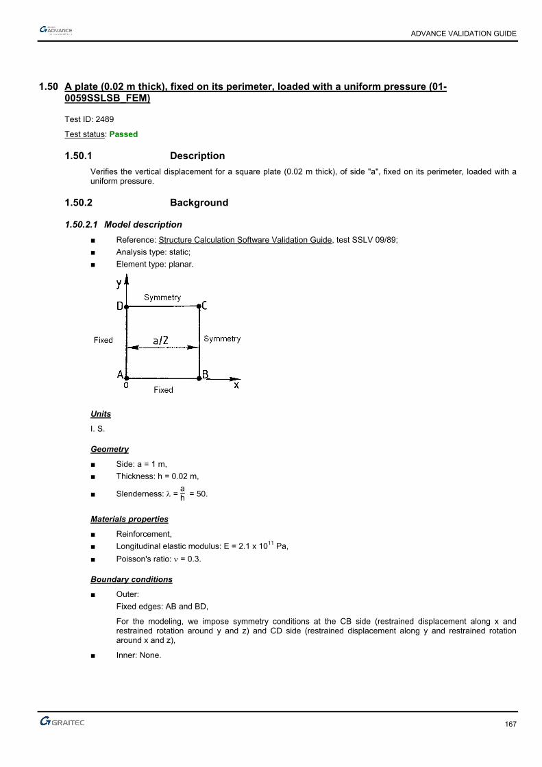
ADVANCE VALIDATION GUIDE
167
1.50 A plate (0.02 m thick), fixed on its perimeter, loaded with a uniform pressure (01-0059SSLSB_FEM)
Test ID: 2489
Test status: Passed
1.50.1 Description
Verifies the vertical displacement for a square plate (0.02 m thick), of side "a", fixed on its perimeter, loaded with a uniform pressure.
1.50.2 Background
1.50.2.1 Model description
■ Reference: Structure Calculation Software Validation Guide, test SSLV 09/89;
■ Analysis type: static;
■ Element type: planar.
Units
I. S.
Geometry
■ Side: a = 1 m,
■ Thickness: h = 0.02 m,
■ Slenderness: = ah = 50.
Materials properties
■ Reinforcement,
■ Longitudinal elastic modulus: E = 2.1 x 10¹¹ Pa,
■ Poisson's ratio: = 0.3.
Boundary conditions
■ Outer:
Fixed edges: AB and BD,
For the modeling, we impose symmetry conditions at the CB side (restrained displacement along x and restrained rotation around y and z) and CD side (restrained displacement along y and restrained rotation around x and z),
■ Inner: None.

ADVANCE VALIDATION GUIDE
168
Loading
■ External: 1 MPa uniform pressure,
■ Internal: None.
1.50.2.2 Vertical displacement at C
Reference solution
This problem has a precise analytical solution only for thin plates. Therefore we propose the solutions obtained with Serendip elements with 20 nodes or thick plate elements of 4 nodes. The expected result should be between these values at ± 5%.
Finite elements modeling
■ Planar element: plate, imposed mesh,
■ 289 nodes,
■ 256 surface quadrangles.
1.50.2.3 Theoretical results
Solver Result name Result description Reference value
CM2 Dz Vertical displacement in point C [m] -0.83480 x 10⁻²
1.50.3 Calculated results
Result name Result description Value Error
Dz Vertical displacement in point C [cm] -0.82559 cm 1.10%

ADVANCE VALIDATION GUIDE
169
1.51 A plate (0.01 m thick), fixed on its perimeter, loaded with a uniform pressure (01-0057SSLSB_FEM)
Test ID: 2487
Test status: Passed
1.51.1 Description
Verifies the vertical displacement for a square plate (0.01 m thick), of side "a", fixed on its perimeter, loaded with a uniform pressure.
1.51.2 Background
1.51.2.1 Model description
■ Reference: Structure Calculation Software Validation Guide, test SSLV 09/89;
■ Analysis type: static;
■ Element type: planar.
Units
I. S.
Geometry
■ Side: a = 1 m,
■ Thickness: h = 0.01 m,
■ Slenderness: = ah = 100.
Materials properties
■ Reinforcement,
■ Longitudinal elastic modulus: E = 2.1 x 10¹¹ Pa,
■ Poisson's ratio: = 0.3.
Boundary conditions
■ Outer:
Fixed sides: AB and BD,
For the modeling, we impose symmetry conditions at the CB side (restrained displacement along x and restrained rotation around y and z) and CD side (restrained displacement along y and restrained rotation around x and z),
■ Inner: None.

ADVANCE VALIDATION GUIDE
170
Loading
■ External: 1 MPa uniform pressure,
■ Internal: None.
1.51.2.2 Vertical displacement at C
Reference solution
This problem has a precise analytical solution only for thin plates. Therefore we propose the solutions obtained with Serendip elements with 20 nodes or thick plate elements of 4 nodes. The expected result should be between these values at 5%.
Finite elements modeling
■ Planar element: plate, imposed mesh,
■ 289 nodes,
■ 256 surface quadrangles.
1.51.2.3 Theoretical results
Solver Result name Result description Reference value
CM2 Dz Vertical displacement in point C [m] -6.639 x 10⁻²
1.51.3 Calculated results
Result name Result description Value Error
Dz Vertical displacement in point C [cm] -6.56563 cm 1.11%

ADVANCE VALIDATION GUIDE
171
1.52 Pinch cylindrical shell (01-0048SSLSB_FEM)
Test ID: 2478
Test status: Passed
1.52.1 Description
A cylinder of length L is pinched by 2 diametrically opposite forces (F). The vertical displacement is verified.
1.52.2 Background
■ Reference: Structure Calculation Software Validation Guide, test SSLS 20/89;
■ Analysis type: static, linear elastic;
■ Element type: planar.
1.52.2.1 Model description
A cylinder of length L is pinched by 2 diametrically opposite forces (F).
Pinch cylindrical shell
01-0048SSLSB_FEM
Units
I. S.
Geometry
■ Length: L = 10.35 m (total length),
■ Radius: R = 4.953 m,
■ Thickness: h = 0.094 m.

ADVANCE VALIDATION GUIDE
172
Materials properties
■ Longitudinal elastic modulus: E = 10.5 x 10⁶ Pa,
■ Poisson's ratio: = 0.3125.
Boundary conditions
■ Outer: For the modeling, we consider only half of the cylinder, so we impose symmetry conditions (nodes in the horizontal xz plane are restrained in translation along y and in rotation along x and z),
■ Inner: None.
Loading
■ External: 2 punctual loads F = 100 N,
■ Internal: None.
1.52.2.2 Vertical displacement at point A
Reference solution
The reference solution is determined by averaging the results of several calculation software with implemented finite elements method. 2% uncertainty about the reference solution.
Finite elements modeling
■ Planar element: shell, imposed mesh,
■ 777 nodes,
■ 720 surface quadrangles.
1.52.2.3 Theoretical result
Solver Result name Result description Reference value
CM2 DZ Vertical displacement in point A [m] -113.9 x 10⁻³
1.52.3 Calculated results
Result name Result description Value Error
DZ Vertical displacement in point A [mm] -113.3 mm 0.53%
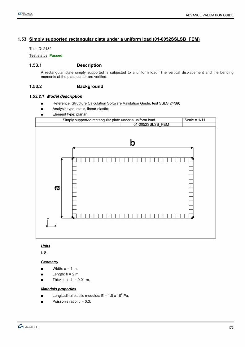
ADVANCE VALIDATION GUIDE
173
1.53 Simply supported rectangular plate under a uniform load (01-0052SSLSB_FEM)
Test ID: 2482
Test status: Passed
1.53.1 Description
A rectangular plate simply supported is subjected to a uniform load. The vertical displacement and the bending moments at the plate center are verified.
1.53.2 Background
1.53.2.1 Model description
■ Reference: Structure Calculation Software Validation Guide, test SSLS 24/89;
■ Analysis type: static, linear elastic;
■ Element type: planar.
Simply supported rectangular plate under a uniform load Scale = 1/11 01-0052SSLSB_FEM
Units
I. S.
Geometry
■ Width: a = 1 m,
■ Length: b = 2 m,
■ Thickness: h = 0.01 m,
Materials properties
■ Longitudinal elastic modulus: E = 1.0 x 10⁷ Pa,
■ Poisson's ratio: = 0.3.
ADVANCE VALIDATION GUIDE
174
Boundary conditions
■ Outer: Simple support on the plate perimeter (null displacement along z-axis),
■ Inner: None.
Loading
■ External: Normal pressure of plate p = pZ = -1.0 Pa,
■ Internal: None.
1.53.2.2 Vertical displacement and bending moment at the center of the plate
Reference solution
Love-Kirchhoff thin plates theory.
Finite elements modeling
■ Planar element: plate, imposed mesh,
■ 435 nodes,
■ 392 surface quadrangles.
1.53.2.3 Theoretical background
Solver Result name Result description Reference value
CM2 DZ Vertical displacement at plate center [m] -1.1060 x 10⁻²
CM2 Mxx MX bending moment at plate center [Nm] -0.1017
CM2 Myy MY bending moment at plate center [Nm] -0.0464
1.53.3 Calculated results
Result name Result description Value Error
DZ Vertical displacement at plate center [cm] -1.10238 cm 0.33%
Mxx Mx bending moment at plate center [Nm] -0.101737 N*m -0.04%
Myy My bending moment at plate center [Nm] -0.0462457 N*m 0.33%

ADVANCE VALIDATION GUIDE
175
1.54 Triangulated system with hinged bars (01-0056SSLLB_FEM)
Test ID: 2486
Test status: Passed
1.54.1 Description
A truss with hinged bars is placed on three punctual supports (subjected to imposed displacements) and is loaded with two punctual forces. A thermal load is applied to all the bars. The traction force and the vertical displacement are verified.
1.54.2 Background
1.54.2.1 Model description
■ Reference: Structure Calculation Software Validation Guide, test SSLL 12/89;
■ Analysis type: static (plane problem);
■ Element type: linear.
Units
I. S.
Geometry
■ = 30°,
■ Section A1 = 1.41 x 10⁻³ m2,
■ Section A2 = 2.82 x 10⁻³ m2.
Materials properties
■ Longitudinal elastic modulus: E =2.1 x 10¹¹ Pa,
■ Coefficient of linear expansion: = 10-5 °C-1.
Boundary conditions
■ Outer:
► Hinge at A (uA = vA = 0),
► Roller supports at B and C ( uB = v’C = 0),
■ Inner: None.

ADVANCE VALIDATION GUIDE
176
Loading
■ External:
► Support displacement: vA = -0.02 m ; vB = -0.03 m ; v’C = -0.015 m ,
► Punctual loads: FE = -150 KN ; FF = -100 KN,
► Expansion effect on all bars for a temperature variation of 150° in relation with the assembly temperature (specified geometry),
■ Internal: None.
1.54.2.2 Tension force in BD bar
Reference solution
Determining the hyperstatic unknown with the section cut method.
Finite elements modeling
■ Linear element: S beam, automatic mesh,
■ 11 nodes,
■ 17 S beams + 1 rigid S beam for the modeling of the simple support at C.
1.54.2.3 Vertical displacement at D
Reference solution
vD displacement was determined by several software with implemented finite elements method.
Finite elements modeling
■ Linear element: S beam, automatic mesh,
■ 11 nodes,
■ 17 S beams + 1 rigid S beam for the modeling of simple support at C.
Deformed shape
Triangulated system with hinged bars 01-0056SSLLB_FEM

ADVANCE VALIDATION GUIDE
177
1.54.2.4 Theoretical results
Solver Result name Result description Reference value
CM2 Fx FX traction force on BD bar [N] 43633
CM2 DZ Vertical displacement on point D [m] -0.01618
1.54.3 Calculated results
Result name Result description Value Error
Fx Fx traction force on BD bar [N] 42870.9 N -1.75%
DZ Vertical displacement on point D [m] -0.0162358 m -0.34%

ADVANCE VALIDATION GUIDE
178
1.55 A plate (0.01 m thick), fixed on its perimeter, loaded with a punctual force (01-0062SSLSB_FEM)
Test ID: 2492
Test status: Passed
1.55.1 Description
Verifies the vertical displacement for a square plate (0.01 m thick), of side "a", fixed on its perimeter, loaded with a punctual force in the center.
1.55.2 Background
■ Reference: Structure Calculation Software Validation Guide, test SSLV 09/89;
■ Analysis type: static;
■ Element type: planar.
1.55.2.1 Model description
Square plate of side "a".
0.01 m thick plate fixed on its perimeter Scale = 1/5
01-0062SSLSB_FEM
Units
I. S.
Geometry
■ Side: a = 1 m,
■ Thickness: h = 0.01 m,
■ Slenderness: = ah = 100.
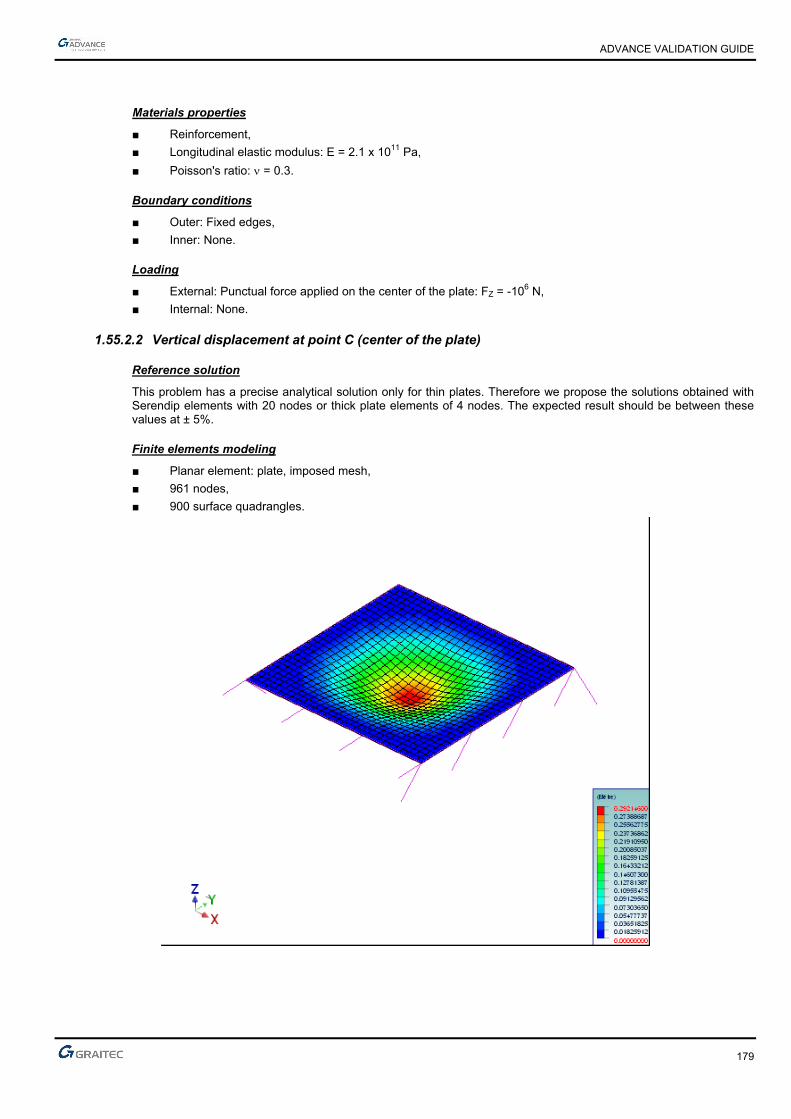
ADVANCE VALIDATION GUIDE
179
Materials properties
■ Reinforcement,
■ Longitudinal elastic modulus: E = 2.1 x 10¹¹ Pa,
■ Poisson's ratio: = 0.3.
Boundary conditions
■ Outer: Fixed edges,
■ Inner: None.
Loading
■ External: Punctual force applied on the center of the plate: FZ = -106 N,
■ Internal: None.
1.55.2.2 Vertical displacement at point C (center of the plate)
Reference solution
This problem has a precise analytical solution only for thin plates. Therefore we propose the solutions obtained with Serendip elements with 20 nodes or thick plate elements of 4 nodes. The expected result should be between these values at ± 5%.
Finite elements modeling
■ Planar element: plate, imposed mesh,
■ 961 nodes,
■ 900 surface quadrangles.
ADVANCE VALIDATION GUIDE
180
1.55.2.3 Theoretical results
Solver Result name Result description Reference value
CM2 DZ Vertical displacement in point C [m] -0.29579
1.55.3 Calculated results
Result name Result description Value Error
DZ Vertical displacement in point C [m] -0.292146 m 1.23%
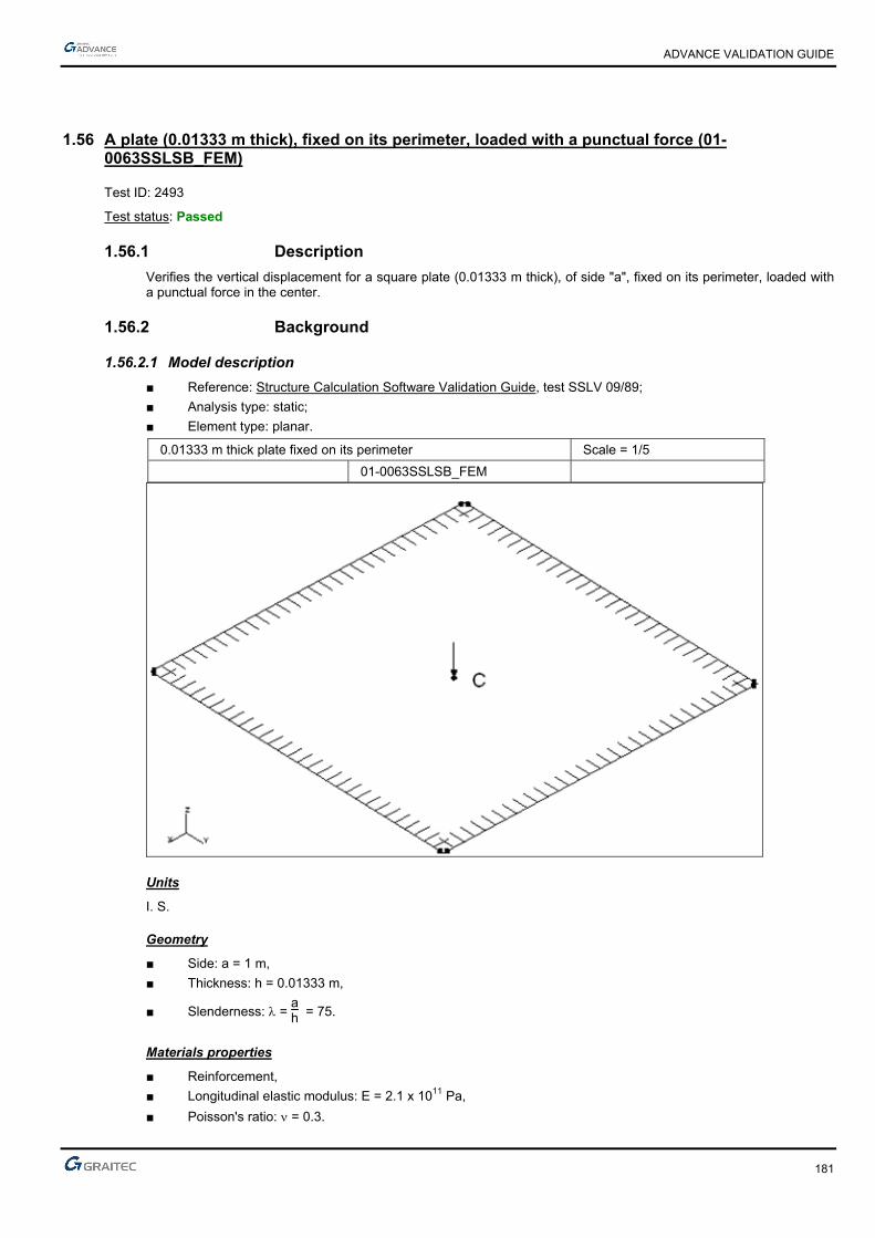
ADVANCE VALIDATION GUIDE
181
1.56 A plate (0.01333 m thick), fixed on its perimeter, loaded with a punctual force (01-0063SSLSB_FEM)
Test ID: 2493
Test status: Passed
1.56.1 Description
Verifies the vertical displacement for a square plate (0.01333 m thick), of side "a", fixed on its perimeter, loaded with a punctual force in the center.
1.56.2 Background
1.56.2.1 Model description
■ Reference: Structure Calculation Software Validation Guide, test SSLV 09/89;
■ Analysis type: static;
■ Element type: planar.
0.01333 m thick plate fixed on its perimeter Scale = 1/5
01-0063SSLSB_FEM
Units
I. S.
Geometry
■ Side: a = 1 m,
■ Thickness: h = 0.01333 m,
■ Slenderness: = ah = 75.
Materials properties
■ Reinforcement,
■ Longitudinal elastic modulus: E = 2.1 x 10¹¹ Pa,
■ Poisson's ratio: = 0.3.

ADVANCE VALIDATION GUIDE
182
Boundary conditions
■ Outer: Fixed sides,
■ Inner: None.
Loading
■ External: Punctual force applied on the center of the plate: FZ = -106 N,
■ Internal: None.
1.56.2.2 Vertical displacement at point C (the center of the plate)
Reference solution
This problem has a precise analytical solution only for thin plates. Therefore we propose the solutions obtained with Serendip elements with 20 nodes or thick plate elements of 4 nodes. The expected result should be between these values at ± 5%.
Finite elements modeling
■ Planar element: plate, imposed mesh,
■ 961 nodes,
■ 900 surface quadrangles.
1.56.2.3 Theoretical results
Solver Result name Result description Reference value
CM2 DZ Vertical displacement in point C [m] -0.12525
1.56.3 Calculated results
Result name Result description Value Error
DZ Vertical displacement in point C [m] -0.124583 m 0.53%

ADVANCE VALIDATION GUIDE
183
1.57 A plate (0.1 m thick), fixed on its perimeter, loaded with a punctual force (01-0066SSLSB_FEM)
Test ID: 2496
Test status: Passed
1.57.1 Description
Verifies the vertical displacement for a square plate (0.1 m thick), of side "a", fixed on its perimeter, loaded with a punctual force in the center.
1.57.2 Background
1.57.2.1 Model description
■ Reference: Structure Calculation Software Validation Guide, test SSLV 09/89;
■ Analysis type: static;
■ Element type: planar.
0.1 m thick plate fixed on its perimeter Scale = 1/5
01-0066SSLSB_FEM
Units
I. S.
Geometry
■ Side: a = 1 m,
■ Thickness: h = 0.1 m,
■ Slenderness: = 10.
Materials properties
■ Reinforcement,
■ Longitudinal elastic modulus: E = 2.1 x 10¹¹ Pa,
■ Poisson's ratio: = 0.3.
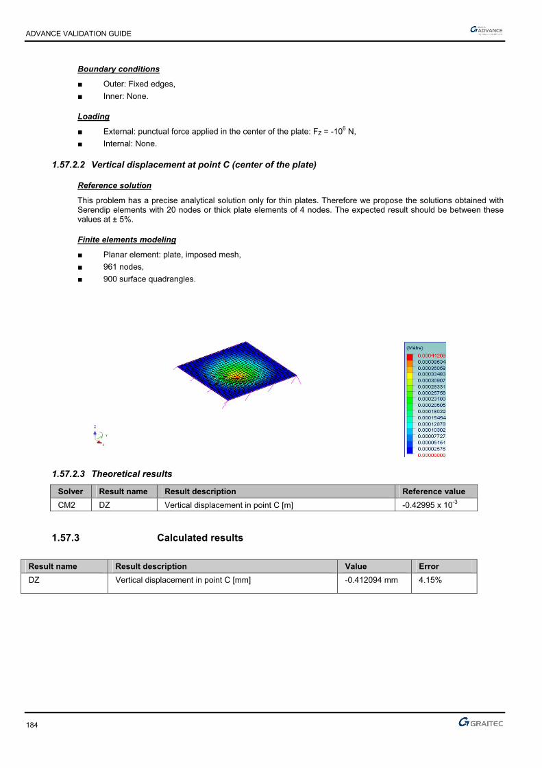
ADVANCE VALIDATION GUIDE
184
Boundary conditions
■ Outer: Fixed edges,
■ Inner: None.
Loading
■ External: punctual force applied in the center of the plate: FZ = -106 N,
■ Internal: None.
1.57.2.2 Vertical displacement at point C (center of the plate)
Reference solution
This problem has a precise analytical solution only for thin plates. Therefore we propose the solutions obtained with Serendip elements with 20 nodes or thick plate elements of 4 nodes. The expected result should be between these values at ± 5%.
Finite elements modeling
■ Planar element: plate, imposed mesh,
■ 961 nodes,
■ 900 surface quadrangles.
1.57.2.3 Theoretical results
Solver Result name Result description Reference value
CM2 DZ Vertical displacement in point C [m] -0.42995 x 10⁻³
1.57.3 Calculated results
Result name Result description Value Error
DZ Vertical displacement in point C [mm] -0.412094 mm 4.15%
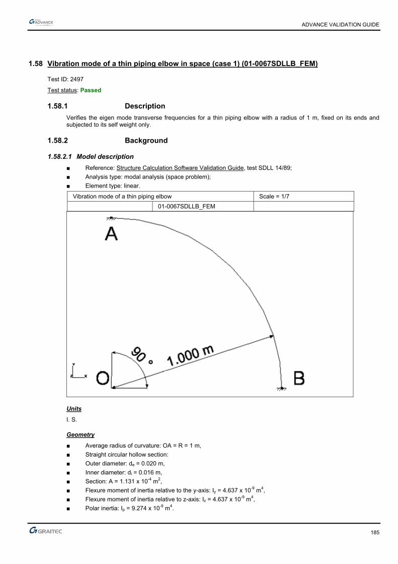
ADVANCE VALIDATION GUIDE
185
1.58 Vibration mode of a thin piping elbow in space (case 1) (01-0067SDLLB_FEM)
Test ID: 2497
Test status: Passed
1.58.1 Description
Verifies the eigen mode transverse frequencies for a thin piping elbow with a radius of 1 m, fixed on its ends and subjected to its self weight only.
1.58.2 Background
1.58.2.1 Model description
■ Reference: Structure Calculation Software Validation Guide, test SDLL 14/89;
■ Analysis type: modal analysis (space problem);
■ Element type: linear.
Vibration mode of a thin piping elbow Scale = 1/7
01-0067SDLLB_FEM
Units
I. S.
Geometry
■ Average radius of curvature: OA = R = 1 m,
■ Straight circular hollow section:
■ Outer diameter: de = 0.020 m,
■ Inner diameter: di = 0.016 m,
■ Section: A = 1.131 x 10⁻⁴ m2,
■ Flexure moment of inertia relative to the y-axis: Iy = 4.637 x 10⁻⁹ m4,
■ Flexure moment of inertia relative to z-axis: Iz = 4.637 x 10⁻⁹ m4,
■ Polar inertia: Ip = 9.274 x 10⁻⁹ m4.

ADVANCE VALIDATION GUIDE
186
■ Points coordinates (in m):
► O ( 0 ; 0 ; 0 )
► A ( 0 ; R ; 0 )
► B ( R ; 0 ; 0 )
Materials properties
■ Longitudinal elastic modulus: E = 2.1 x 10¹¹ Pa,
■ Poisson's ratio: = 0.3,
■ Density: = 7800 kg/m3.
Boundary conditions
■ Outer: Fixed at points A and B,
■ Inner: None.
Loading
■ External: None,
■ Internal: None.
1.58.2.2 Eigen modes frequencies
Reference solution
The Rayleigh method applied to a thin curved beam is used to determine parameters such as:
■ transverse bending:
fj = i
2
2 R2 GIpA
where i = 1,2.
Finite elements modeling
■ Linear element: beam,
■ 11 nodes,
■ 10 linear elements.
Eigen mode shapes

ADVANCE VALIDATION GUIDE
187
1.58.2.3 Theoretical results
Solver Result name Result description Reference value
CM2 Eigen mode Eigen mode Transverse 1 frequency [Hz] 44.23
CM2 Eigen mode Eigen mode Transverse 2 frequency [Hz] 125
1.58.3 Calculated results
Result name Result description Value Error
Eigen mode Transverse 1 frequency [Hz] 44.12 Hz -0.25%
Eigen mode Transverse 2 frequency [Hz] 120.09 Hz -3.93%
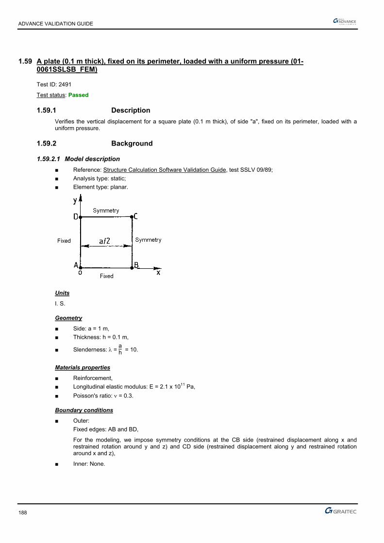
ADVANCE VALIDATION GUIDE
188
1.59 A plate (0.1 m thick), fixed on its perimeter, loaded with a uniform pressure (01-0061SSLSB_FEM)
Test ID: 2491
Test status: Passed
1.59.1 Description
Verifies the vertical displacement for a square plate (0.1 m thick), of side "a", fixed on its perimeter, loaded with a uniform pressure.
1.59.2 Background
1.59.2.1 Model description
■ Reference: Structure Calculation Software Validation Guide, test SSLV 09/89;
■ Analysis type: static;
■ Element type: planar.
Units
I. S.
Geometry
■ Side: a = 1 m,
■ Thickness: h = 0.1 m,
■ Slenderness: = ah = 10.
Materials properties
■ Reinforcement,
■ Longitudinal elastic modulus: E = 2.1 x 10¹¹ Pa,
■ Poisson's ratio: = 0.3.
Boundary conditions
■ Outer:
Fixed edges: AB and BD,
For the modeling, we impose symmetry conditions at the CB side (restrained displacement along x and restrained rotation around y and z) and CD side (restrained displacement along y and restrained rotation around x and z),
■ Inner: None.

ADVANCE VALIDATION GUIDE
189
Loading
■ External: 1 MPa uniform pressure,
■ Internal: None.
1.59.2.2 Vertical displacement at C
Reference solution
This problem has a precise analytical solution only for thin plates. Therefore we propose the solutions obtained with Serendip elements with 20 nodes or thick plate elements of 4 nodes. The expected result should be between these values at ± 5%.
Finite elements modeling
■ Planar element: plate, imposed mesh,
■ 289 nodes,
■ 256 surface quadrangles.
1.59.2.3 Theoretical results
Solver Result name Result description Reference value
CM2 Dz Vertical displacement in point C [m] -0.78661 x 10⁻⁴
1.59.3 Calculated results
Result name Result description Value Error
Dz Vertical displacement in point C [mm] -0.0781846 mm 0.61%
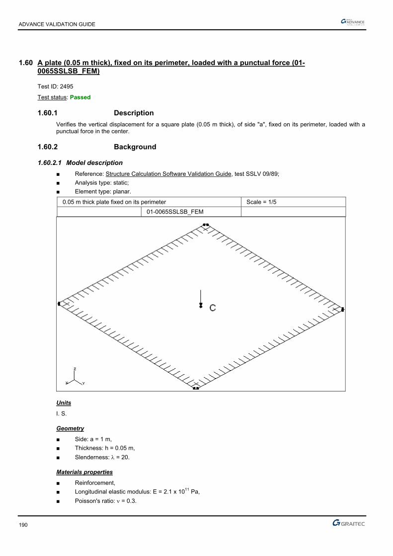
ADVANCE VALIDATION GUIDE
190
1.60 A plate (0.05 m thick), fixed on its perimeter, loaded with a punctual force (01-0065SSLSB_FEM)
Test ID: 2495
Test status: Passed
1.60.1 Description
Verifies the vertical displacement for a square plate (0.05 m thick), of side "a", fixed on its perimeter, loaded with a punctual force in the center.
1.60.2 Background
1.60.2.1 Model description
■ Reference: Structure Calculation Software Validation Guide, test SSLV 09/89;
■ Analysis type: static;
■ Element type: planar.
0.05 m thick plate fixed on its perimeter Scale = 1/5
01-0065SSLSB_FEM
Units
I. S.
Geometry
■ Side: a = 1 m,
■ Thickness: h = 0.05 m,
■ Slenderness: = 20.
Materials properties
■ Reinforcement,
■ Longitudinal elastic modulus: E = 2.1 x 10¹¹ Pa,
■ Poisson's ratio: = 0.3.

ADVANCE VALIDATION GUIDE
191
Boundary conditions
■ Outer: Fixed sides,
■ Inner: None.
Loading
■ External: Punctual force applied at the center of the plate: FZ = -106 N,
■ Internal: None.
1.60.2.2 Vertical displacement at point C center of the plate)
Reference solution
This problem has a precise analytical solution only for thin plates. Therefore we propose the solutions obtained with Serendip elements with 20 nodes or thick plate elements of 4 nodes. The expected result should be between these values at ± 5%.
Finite elements modeling
■ Planar element: plate, imposed mesh,
■ 961 nodes,
■ 900 surface quadrangles.
1.60.2.3 Theoretical results
Solver Result name Result description Reference value
CM2 DZ Vertical displacement in point C [m] -0.2595 x 10⁻²
1.60.3 Calculated results
Result name Result description Value Error
DZ Vertical displacement in point C [m] -0.00257232 m 0.86%

ADVANCE VALIDATION GUIDE
192
1.61 Reactions on supports and bending moments on a 2D portal frame (Rafters) (01-0077SSLPB_FEM)
Test ID: 2500
Test status: Passed
1.61.1 Description
Moments and actions on supports calculation on a 2D portal frame. The purpose of this test is to verify the results of Advance Design for the M. R. study of a 2D portal frame.
1.61.2 Background
1.61.2.1 Model description
■ Reference: Design and calculation of metal structures.
■ Analysis type: static linear;
■ Element type: linear.

ADVANCE VALIDATION GUIDE
193
1.61.2.2 Moments and actions on supports M.R. calculation on a 2D portal frame.
RDM results, for the linear load perpendicular on the rafters, are:
2
qLVV EA H
fh3f3k²h
f5h8
32
²qLHH EA
HhMM DB fhH8
²qLMC
1.61.2.3 Theoretical results
Comparison between theoretical results and the results obtained by Advance Design for a linear load perpendicular on the chords
Solver Result name Result description Reference value
CM2 Fz Vertical reaction V in A [DaN] -1000
CM2 Fz Vertical reaction V in E [DaN] -1000
CM2 Fx Horizontal reaction H in A [DaN] -332.9
CM2 Fx Horizontal reaction H in E [DaN] -332.9
CM2 My Moment in node B [DaNm] 2496.8
CM2 My Moment in node D [DaNm] -2496.8
CM2 My Moment in node C [DaNm] -1671
1.61.3 Calculated results
Result name Result description Value Error
Fz Vertical reaction V on node A [daN] -1000 daN 0.00%
Fz Vertical reaction V on node E [daN] -1000 daN 0.00%
Fx Horizontal reaction H on node A [daN] -332.665 daN 0.07%
Fx Horizontal reaction H on node E [daN] -332.665 daN 0.07%
My Moment in node B [daNm] 2494.99 daN*m -0.07%
My Moment in node D [daNm] -2494.99 daN*m 0.07%
My Moment in node C [daNm] -1673.35 daN*m -0.14%
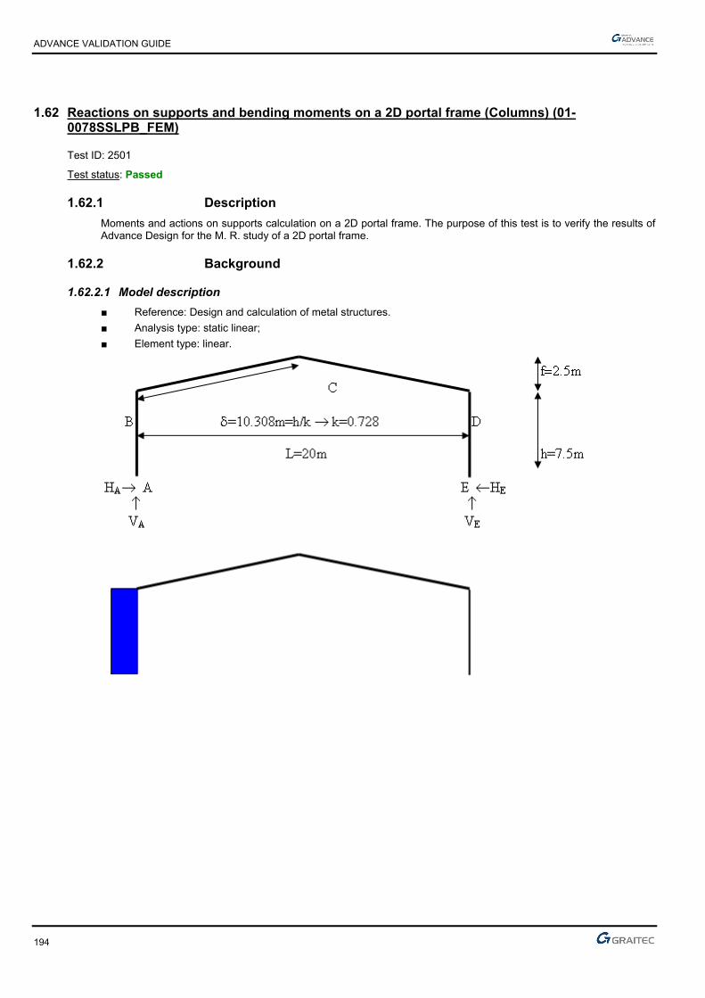
ADVANCE VALIDATION GUIDE
194
1.62 Reactions on supports and bending moments on a 2D portal frame (Columns) (01-0078SSLPB_FEM)
Test ID: 2501
Test status: Passed
1.62.1 Description
Moments and actions on supports calculation on a 2D portal frame. The purpose of this test is to verify the results of Advance Design for the M. R. study of a 2D portal frame.
1.62.2 Background
1.62.2.1 Model description
■ Reference: Design and calculation of metal structures.
■ Analysis type: static linear;
■ Element type: linear.
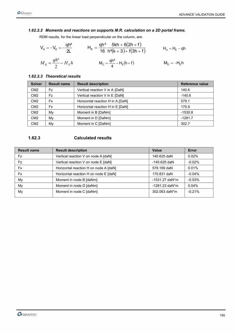
ADVANCE VALIDATION GUIDE
195
1.62.2.2 Moments and reactions on supports M.R. calculation on a 2D portal frame.
RDM results, for the linear load perpendicular on the column, are:
L2
²qhVV EA
fh3f3k²h
fh26kh5
16
²qhHE
qhHH EA
hHqh
M EB 2
² fhH
4
²qhM EC hHM ED
1.62.2.3 Theoretical results
Solver Result name Result description Reference value
CM2 Fz Vertical reaction V in A [DaN] 140.6
CM2 Fz Vertical reaction V in E [DaN] -140.6
CM2 Fx Horizontal reaction H in A [DaN] 579.1
CM2 Fx Horizontal reaction H in E [DaN] 170.9
CM2 My Moment in B [DaNm] -1530.8
CM2 My Moment in D [DaNm] -1281.7
CM2 My Moment in C [DaNm] 302.7
1.62.3 Calculated results
Result name Result description Value Error
Fz Vertical reaction V on node A [daN] 140.625 daN 0.02%
Fz Vertical reaction V on node E [daN] -140.625 daN -0.02%
Fx Horizontal reaction H on node A [daN] 579.169 daN 0.01%
Fx Horizontal reaction H on node E [daN] 170.831 daN -0.04%
My Moment in node B [daNm] -1531.27 daN*m -0.03%
My Moment in node D [daNm] -1281.23 daN*m 0.04%
My Moment in node C [daNm] 302.063 daN*m -0.21%
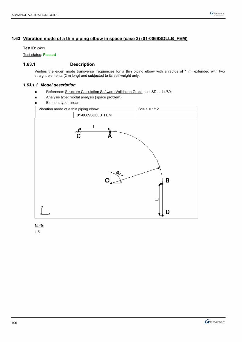
ADVANCE VALIDATION GUIDE
196
1.63 Vibration mode of a thin piping elbow in space (case 3) (01-0069SDLLB_FEM)
Test ID: 2499
Test status: Passed
1.63.1 Description
Verifies the eigen mode transverse frequencies for a thin piping elbow with a radius of 1 m, extended with two straight elements (2 m long) and subjected to its self weight only.
1.63.1.1 Model description
■ Reference: Structure Calculation Software Validation Guide, test SDLL 14/89;
■ Analysis type: modal analysis (space problem);
■ Element type: linear.
Vibration mode of a thin piping elbow Scale = 1/12
01-0069SDLLB_FEM
Units
I. S.

ADVANCE VALIDATION GUIDE
197
Geometry
■ Average radius of curvature: OA = R = 1 m,
■ L = 2 m,
■ Straight circular hollow section:
■ Outer diameter: de = 0.020 m,
■ Inner diameter: di = 0.016 m,
■ Section: A = 1.131 x 10⁻⁴ m2,
■ Flexure moment of inertia relative to the y-axis: Iy = 4.637 x 10⁻⁹ m4,
■ Flexure moment of inertia relative to z-axis: Iz = 4.637 x 10⁻⁹ m4,
■ Polar inertia: Ip = 9.274 x 10⁻⁹ m4.
■ Points coordinates (in m):
► O ( 0 ; 0 ; 0 )
► A ( 0 ; R ; 0 )
► B ( R ; 0 ; 0 )
► C ( -L ; R ; 0 )
► D ( R ; -L ; 0 )
Materials properties
■ Longitudinal elastic modulus: E = 2.1 x 10¹¹ Pa,
■ Poisson's ratio: = 0.3,
■ Density: = 7800 kg/m3.
Boundary conditions
■ Outer:
► Fixed at points C and D
► At A: translation restraint along y and z,
► At B: translation restraint along x and z,
■ Inner: None.
Loading
■ External: None,
■ Internal: None.

ADVANCE VALIDATION GUIDE
198
1.63.1.2 Eigen modes frequencies
Reference solution
The Rayleigh method applied to a thin curved beam is used to determine parameters such as:
■ transverse bending:
fj = i
2
2 R2 GIpA
where i = 1,2 with i = 1,2:
Finite elements modeling
■ Linear element: beam,
■ 41 nodes,
■ 40 linear elements.
Eigen mode shapes
1.63.1.3 Theoretical results
Reference
Solver Result name Result description Reference value
CM2 Eigen mode Eigen mode Transverse 1 frequency [Hz] 17.900
CM2 Eigen mode Eigen mode Transverse 2 frequency [Hz] 24.800
1.63.2 Calculated results
Result name Result description Value Error
Eigen mode Transverse 1 frequency [Hz] 17.65 Hz -1.40%
Eigen mode Transverse 2 frequency [Hz] 24.43 Hz -1.49%

ADVANCE VALIDATION GUIDE
199
1.64 A plate (0.05 m thick), fixed on its perimeter, loaded with a uniform pressure (01-0060SSLSB_FEM)
Test ID: 2490
Test status: Passed
1.64.1 Description
Verifies the vertical displacement for a square plate (0.05 m thick), of side "a", fixed on its perimeter, loaded with a uniform pressure.
1.64.2 Background
1.64.2.1 Model description
■ Reference: Structure Calculation Software Validation Guide, test SSLV 09/89;
■ Analysis type: static;
■ Element type: planar.
Units
I. S.
Geometry
■ Side: a = 1 m,
■ Thickness: h = 0.05 m,
■ Slenderness: = ah = 20.
Materials properties
■ Reinforcement,
■ Longitudinal elastic modulus: E = 2.1 x 10¹¹ Pa,
■ Poisson's ratio: = 0.3.
Boundary conditions
■ Outer:
Fixed edges: AB and BD,
For the modeling, we impose symmetry conditions at the CB side (restrained displacement along x and restrained rotation around y and z) and CD side (restrained displacement along y and restrained rotation around x and z),
■ Inner: None.

ADVANCE VALIDATION GUIDE
200
Loading
■ External: 1 MPa uniform pressure,
■ Internal: None.
1.64.2.2 Vertical displacement at C
Reference solution
This problem has a precise analytical solution only for thin plates. Therefore we propose the solutions obtained with Serendip elements with 20 nodes or thick plate elements of 4 nodes. The expected result should be between these values at ± 5%.
Finite elements modeling
■ Planar element: plate, imposed mesh,
■ 289 nodes,
■ 256 surface quadrangles.
1.64.2.3 Theoretical results
Solver Result name Result description Reference value
CM2 Dz Vertical displacement in point C [m] -0.55474 x 10⁻³
1.64.3 Calculated results
Result name Result description Value Error
Dz Vertical displacement in point C [cm] -0.0549874 cm 0.88%

ADVANCE VALIDATION GUIDE
201
1.65 A plate (0.02 m thick), fixed on its perimeter, loaded with a punctual force (01-0064SSLSB_FEM)
Test ID: 2494
Test status: Passed
1.65.1 Description
Verifies the vertical displacement for a square plate (0.02 m thick), of side "a", fixed on its perimeter, loaded with a punctual force in the center.
1.65.2 Background
1.65.2.1 Model description
■ Reference: Structure Calculation Software Validation Guide, test SSLV 09/89;
■ Analysis type: static;
■ Element type: planar.
0.02 m thick plate fixed on its perimeter Scale = 1/5
01-0064SSLSB_FEM
Units
I. S.
Geometry
■ Side: a = 1 m,
■ Thickness: h = 0.02 m,
■ Slenderness: = 50.
Materials properties
■ Reinforcement,
■ Longitudinal elastic modulus: E = 2.1 x 10¹¹ Pa,
■ Poisson's ratio: = 0.3.

ADVANCE VALIDATION GUIDE
202
Boundary conditions
■ Outer: Fixed edges,
■ Inner: None.
Loading
■ External: punctual force applied in the center of the plate: FZ = -106 N,
■ Internal: None.
1.65.2.2 Vertical displacement at point C (the center of the plate)
Reference solution
This problem has a precise analytical solution only for thin plates. Therefore we propose the solutions obtained with Serendip elements with 20 nodes or thick plate elements of 4 nodes. The expected result should be between these values at ± 5%.
Finite elements modeling
■ Planar element: plate, imposed mesh,
■ 961 nodes,
■ 900 surface quadrangles.
1.65.2.3 Theoretical results
Solver Result name Result description Reference value
CM2 DZ Vertical displacement in point C [m] -0.037454
1.65.3 Calculated results
Result name Result description Value Error
DZ Vertical displacement in point C [m] -0.0369818 m 1.26%
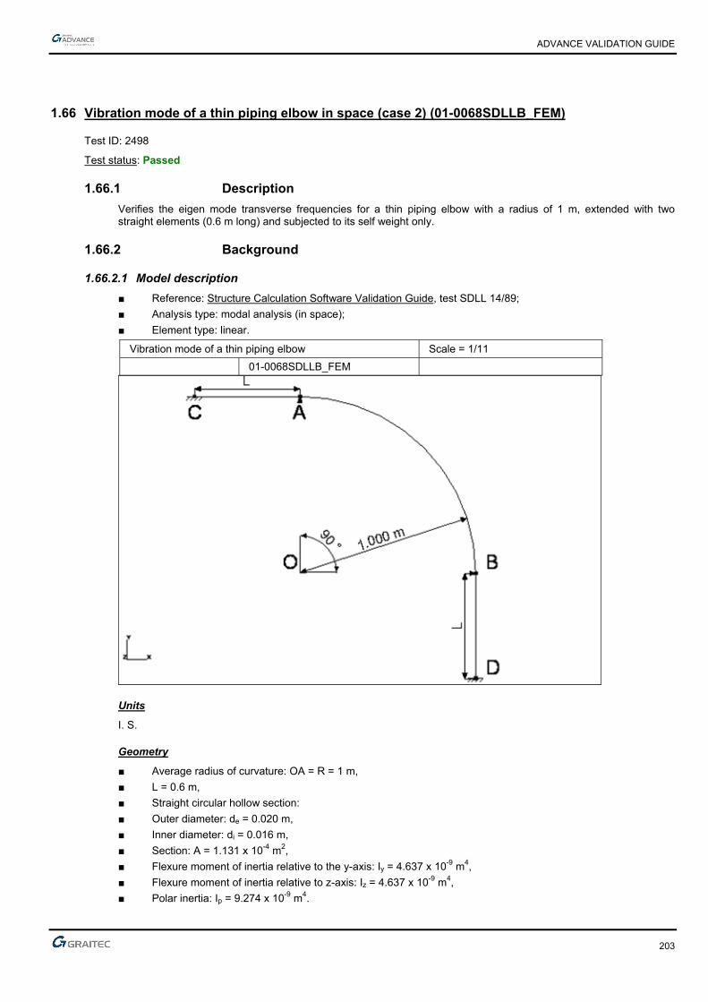
ADVANCE VALIDATION GUIDE
203
1.66 Vibration mode of a thin piping elbow in space (case 2) (01-0068SDLLB_FEM)
Test ID: 2498
Test status: Passed
1.66.1 Description
Verifies the eigen mode transverse frequencies for a thin piping elbow with a radius of 1 m, extended with two straight elements (0.6 m long) and subjected to its self weight only.
1.66.2 Background
1.66.2.1 Model description
■ Reference: Structure Calculation Software Validation Guide, test SDLL 14/89;
■ Analysis type: modal analysis (in space);
■ Element type: linear.
Vibration mode of a thin piping elbow Scale = 1/11
01-0068SDLLB_FEM
Units
I. S.
Geometry
■ Average radius of curvature: OA = R = 1 m,
■ L = 0.6 m,
■ Straight circular hollow section:
■ Outer diameter: de = 0.020 m,
■ Inner diameter: di = 0.016 m,
■ Section: A = 1.131 x 10⁻⁴ m2,
■ Flexure moment of inertia relative to the y-axis: Iy = 4.637 x 10⁻⁹ m4,
■ Flexure moment of inertia relative to z-axis: Iz = 4.637 x 10⁻⁹ m4,
■ Polar inertia: Ip = 9.274 x 10⁻⁹ m4.
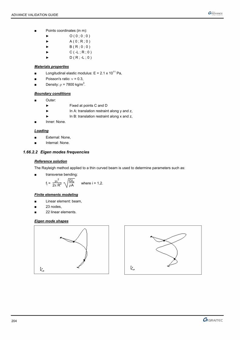
ADVANCE VALIDATION GUIDE
204
■ Points coordinates (in m):
► O ( 0 ; 0 ; 0 )
► A ( 0 ; R ; 0 )
► B ( R ; 0 ; 0 )
► C ( -L ; R ; 0 )
► D ( R ; -L ; 0 )
Materials properties
■ Longitudinal elastic modulus: E = 2.1 x 10¹¹ Pa,
■ Poisson's ratio: = 0.3,
■ Density: = 7800 kg/m3.
Boundary conditions
■ Outer:
► Fixed at points C and D
► In A: translation restraint along y and z,
► In B: translation restraint along x and z,
■ Inner: None.
Loading
■ External: None,
■ Internal: None.
1.66.2.2 Eigen modes frequencies
Reference solution
The Rayleigh method applied to a thin curved beam is used to determine parameters such as:
■ transverse bending:
fj = i
2
2 R2 GIpA
where i = 1,2.
Finite elements modeling
■ Linear element: beam,
■ 23 nodes,
■ 22 linear elements.
Eigen mode shapes
ADVANCE VALIDATION GUIDE
205
1.66.2.3 Theoretical results
Solver Result name Result description Reference value
CM2 Eigen mode Eigen mode Transverse 1 frequency [Hz] 33.4
CM2 Eigen mode Eigen mode Transverse 2 frequency [Hz] 100
1.66.3 Calculated results
Result name Result description Value Error
Eigen mode Transverse 1 frequency [Hz] 33.19 Hz -0.63%
Eigen mode Transverse 2 frequency [Hz] 94.62 Hz -5.38%

ADVANCE VALIDATION GUIDE
206
1.67 Slender beam of variable rectangular section (fixed-fixed) (01-0086SDLLB_FEM)
Test ID: 2504
Test status: Passed
1.67.1 Description
Verifies the eigen modes (flexion) for a slender beam with variable rectangular section (fixed-fixed).
1.67.2 BackgroundOverview
1.67.2.1 Model description
■ Reference: Structure Calculation Software Validation Guide, test SDLL 10/89;
■ Analysis type: modal analysis (plane problem);
■ Element type: linear.
Units
I. S.
Geometry
■ Length: L = 0.6 m,
■ Constant thickness: h = 0.01 m
■ Initial section:
► b0 = 0.03 m
► A0 = 3 x 10⁻⁴ m²
■ Section variation:
► with ( = 1)
► b = b0e-2x
► A = A0e-2x
Materials properties
■ E = 2 x 10¹¹ Pa
■ = 0.3
■ = 7800 kg/m3
Boundary conditions
■ Outer:
► Fixed at end x = 0,
► Fixed at end x = 0.6 m.
■ Inner: None.
Loading
■ External: None,
■ Internal: None.
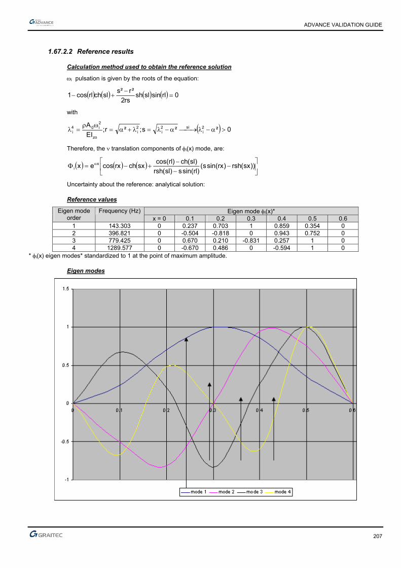
ADVANCE VALIDATION GUIDE
207
1.67.2.2 Reference results
Calculation method used to obtain the reference solution
i pulsation is given by the roots of the equation:
0rlsinslshrs2
²r²sslchrlcos1
with
0²²s;²r;EI
A 2i
si2i
2i
zo
2i04
i
Therefore, the translation components of i(x) mode, are:
))sx(rsh)rxsin(s()rlsin(s)sl(rsh
)sl(ch)rlcos(sxchrxcosex x
i
Uncertainty about the reference: analytical solution:
Reference values
Eigen mode i(x)* Eigen mode order
Frequency (Hz) x = 0 0.1 0.2 0.3 0.4 0.5 0.6
1 143.303 0 0.237 0.703 1 0.859 0.354 0 2 396.821 0 -0.504 -0.818 0 0.943 0.752 0 3 779.425 0 0.670 0.210 -0.831 0.257 1 0 4 1289.577 0 -0.670 0.486 0 -0.594 1 0
* i(x) eigen modes* standardized to 1 at the point of maximum amplitude.
Eigen modes

ADVANCE VALIDATION GUIDE
208
1.67.2.3 Theoretical results
Solver Result name Result description Reference value
CM2 Eigen mode Frequency of eigen mode 1 [Hz] 143.303
CM2 Eigen mode Frequency of eigen mode 2 [Hz] 396.821
CM2 Eigen mode Frequency of eigen mode 3 [Hz] 779.425
CM2 Eigen mode Frequency of eigen mode 4 [Hz] 1289.577
1.67.3 Calculated results
Result name Result description Value Error
Frequency of eigen mode 1 [Hz] 145.88 Hz 1.80%
Frequency of eigen mode 2 [Hz] 400.26 Hz 0.87%
Frequency of eigen mode 3 [Hz] 783.15 Hz 0.48%
Frequency of eigen mode 4 [Hz] 1293.42 Hz 0.30%
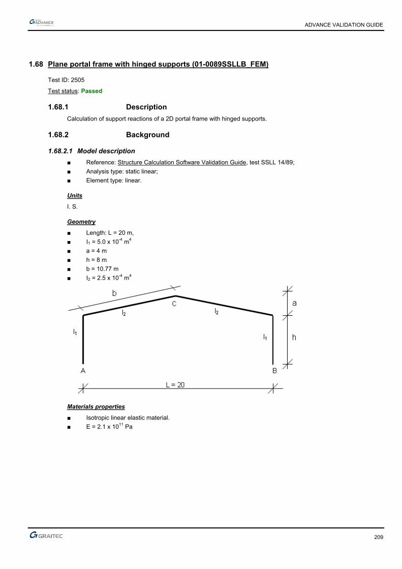
ADVANCE VALIDATION GUIDE
209
1.68 Plane portal frame with hinged supports (01-0089SSLLB_FEM)
Test ID: 2505
Test status: Passed
1.68.1 Description
Calculation of support reactions of a 2D portal frame with hinged supports.
1.68.2 Background
1.68.2.1 Model description
■ Reference: Structure Calculation Software Validation Guide, test SSLL 14/89;
■ Analysis type: static linear;
■ Element type: linear.
Units
I. S.
Geometry
■ Length: L = 20 m,
■ I1 = 5.0 x 10⁻⁴ m4
■ a = 4 m
■ h = 8 m
■ b = 10.77 m
■ I2 = 2.5 x 10⁻⁴ m4
Materials properties
■ Isotropic linear elastic material.
■ E = 2.1 x 10¹¹ Pa

ADVANCE VALIDATION GUIDE
210
Boundary conditions
Hinged base plates A and B (uA = vA = 0 ; uB = vB = 0).
Loading
■ p = -3 000 N/m
■ F1 = -20 000 N
■ F2 = -10 000 N
■ M = -100 000 Nm
1.68.2.2 Calculation method used to obtain the reference solution
■ K = (I2/b)(h/I1)
■ p = a/h
■ m = 1 + p
■ B = 2(K + 1) + m
■ C = 1 + 2m
■ N = B + mC
■ VA = 3pl/8 + F1/2 – M/l + F2h/l
■ HA = pl²(3 + 5m)/(32Nh) + (F1l/(4h))(C/N) + F2(1-(B + C)/(2N)) + (3M/h)((1 + m)/(2N))
1.68.2.3 Reference values
Point Magnitudes and units Value A V, vertical reaction (N) 31 500.0 A H, horizontal reaction (N) 20 239.4 C vc (m) -0.03072
1.68.2.4 Theoretical results
Solver Result name Result description Reference value
CM2 Fz Vertical reaction V in point A [N] -31500
CM2 Fx Horizontal reaction H in point A [N] -20239.4
CM2 DZ vc displacement in point C [m] -0.03072
1.68.3 Calculated results
Result name Result description Value Error
Fz Vertical reaction V in point A [N] -31500 N 0.00%
Fx Horizontal reaction H in point A [N] -20239.3 N 0.00%
DZ Displacement in point C [m] -0.0307191 m 0.00%
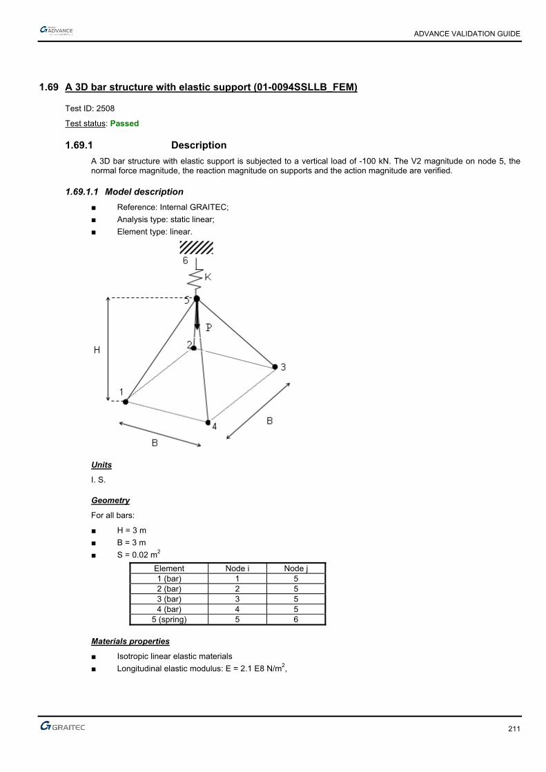
ADVANCE VALIDATION GUIDE
211
1.69 A 3D bar structure with elastic support (01-0094SSLLB_FEM)
Test ID: 2508
Test status: Passed
1.69.1 Description
A 3D bar structure with elastic support is subjected to a vertical load of -100 kN. The V2 magnitude on node 5, the normal force magnitude, the reaction magnitude on supports and the action magnitude are verified.
1.69.1.1 Model description
■ Reference: Internal GRAITEC;
■ Analysis type: static linear;
■ Element type: linear.
Units
I. S.
Geometry
For all bars:
■ H = 3 m
■ B = 3 m
■ S = 0.02 m2
Element Node i Node j 1 (bar) 1 5 2 (bar) 2 5 3 (bar) 3 5 4 (bar) 4 5
5 (spring) 5 6
Materials properties
■ Isotropic linear elastic materials
■ Longitudinal elastic modulus: E = 2.1 E8 N/m2,

ADVANCE VALIDATION GUIDE
212
Boundary conditions
■ Outer: At node 5: K = 50000 kN/m ;
■ Inner: None.
Loading
■ External: Vertical load at node: P = -100 kN,
■ Internal: None.
1.69.1.2 Theoretical results
System solution
2
22 B
HL . Also, U1 = V1 = U5 = U6 = V6 = 0
■ Stiffness matrix of bar 1
1L
2x= where
.12
1.1
2
1)(.).1()(
jiji uuuuL
xu
L
xxu
ADVANCE VALIDATION GUIDE
213
in the local coordinate system:
)(
)(
)(
)(
0000
0101
0000
0101
)(
)(
11
11
4
1
4
14
1
4
12
=
2
2
1
2
1
2
12
1
1
1
1
101
j
j
i
i
j
i
L Te
T
v
v
u
v
u
L
ESu
u
L
ESd
L
ES
dL
ESdxBBESdVBHBke
where
)v(
)u(
)v(
)u(
0000
0101
0000
0101
L
ESk
5
5
1
1
1
The elementary matrix ek expressed in the global coordinate system XY is the following: ( angle allowing
the transition from the global base to the local base):
22
22
22
22
e
eeeT
ee
sinsincossinsincos
sincoscossincoscos
sinsincossinsincos
sincoscossincoscos
L
ESK
cossin00
sincos00
00cossin
00sincos
Ravec RkRK
Knowing that L
Hsin and
2cos
L
B, then:
2
2
22
2
22
L2
HBcossin
L
Hsin
L2
Bcos
)(
)(
)(
)(
22
2222
22
2222
:)D
H(arctan =5,1 nodes 1element for
5
5
1
1
22
22
22
22
31
V
U
V
U
HHB
HHB
HBBHBB
HHB
HHB
HBBHBB
L
ESK
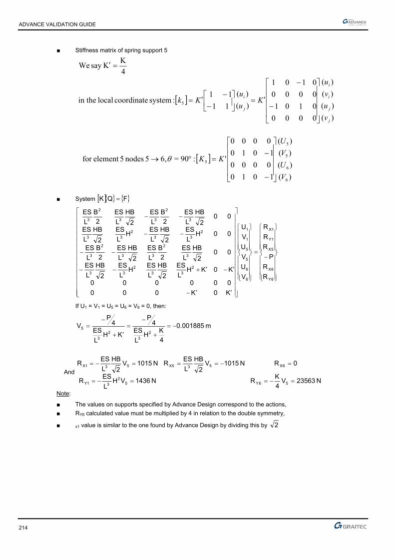
ADVANCE VALIDATION GUIDE
214
■ Stiffness matrix of spring support 5
)(
)(
)(
)(
0000
0101
0000
0101
)(
)(
11
11 :system coordinate local in the
4
KKsay We
5
j
j
i
i
j
i
v
u
v
u
Ku
uKk
)(
)(
)(
)(
1010
0000
1010
0000
':90=6,5 nodes 5element for
6
6
5
5
5
V
U
V
U
KK
■ System FQK
6Y
6X
5X
1Y
1X
6
6
5
5
1
1
2
33
2
33
3
2
33
2
3
2
33
2
33
3
2
33
2
3
R
R
P
R
R
R
V
U
V
U
V
U
K0K000
000000
K0KHL
ES
2
HB
L
ESH
L
ES
2
HB
L
ES
002
HB
L
ES
2
B
L
ES
2
HB
L
ES
2
B
L
ES
00HL
ES
2
HB
L
ESH
L
ES
2
HB
L
ES
002
HB
L
ES
2
B
L
ES
2
HB
L
ES
2
B
L
ES
If U1 = V1 = U5 = U6 = V6 = 0, then:
m 001885.0
4
KH
L
ES4
P
KHL
ES4
PV
2
3
2
3
5
And
N 23563V4
KRN 1436VH
L
ESR
0RN 1015V2
HB
L
ESRN 1015V
2
HB
L
ESR
56Y52
31Y
6X535X531X
Note:
■ The values on supports specified by Advance Design correspond to the actions,
■ RY6 calculated value must be multiplied by 4 in relation to the double symmetry,
■ x1 value is similar to the one found by Advance Design by dividing this by 2
ADVANCE VALIDATION GUIDE
215
Effort in bar 1:
1759
1759
11
11 and
200
200
002
002
5
1
5
1
5
5
1
1
5
5
1
1
N
N
u
u
L
ES
V
U
V
U
L
B
L
HL
H
L
BL
B
L
HL
H
L
B
v
u
v
u
5
1
5
1
5
5
1
1
5
5
1
1
11
11 and
cossin00
sincos00
00cossin
00sincos
N
N
u
u
L
ES
V
U
V
U
v
u
v
u
Reference values
Point Magnitude Units Value
5 V2 m -1.885 10-3 All bars Normal force N -1759
Supports 1, 3, 4 and 5 Fz action N -1436 Supports 1, 3, 4 and 5 Action Fx=Fy N 7182/1015
Support 6 Fz action N 23563 x 4=94253
Finite elements modeling
■ Linear element: beam, automatic mesh,
■ 5 nodes,
■ 4 linear elements.

ADVANCE VALIDATION GUIDE
216
Deformed shape
Normal forces diagram

ADVANCE VALIDATION GUIDE
217
1.69.1.3 Reference values
Solver Result name Result description Reference value
CM2 D V2 magnitude on node 5 [m] -1.885 10-3
CM2 Fx Normal force magnitude on bar 1 [N] -1759
CM2 Fx Normal force magnitude on bar 2 [N] -1759
CM2 Fx Normal force magnitude on bar 3 [N] -1759
CM2 Fx Normal force magnitude on bar 4 [N] -1759
CM2 Fz Fz reaction magnitude on support 1 [N] 1436
CM2 Fz Fz reaction magnitude on support 3 [N] 1436
CM2 Fz Fz reaction magnitude on support 4 [N] 1436
CM2 Fz Fz reaction magnitude on support 5 [N] 1436
CM2 Fx Action Fx magnitude on support 1 [N] -718
CM2 Fx Action Fx magnitude on support 3 [N] 718
CM2 Fx Action Fx magnitude on support 4 [N] 718
CM2 Fx Action Fx magnitude on support 5 [N] -718
CM2 Fy Action Fy magnitude on support 1 [N] -718
CM2 Fy Action Fy magnitude on support 3 [N] -718
CM2 Fy Action Fy magnitude on support 4 [N] 718
CM2 Fy Action Fy magnitude on support 5 [N] 718
CM2 Fz Fz reaction magnitude on support 6 [N] 23563 x 4=94253
1.69.2 Calculated results
Result name Result description Value Error
D Displacement on node 5 [mm] 1.88508 mm 0.00%
Fx Normal force magnitude on bar 1 [N] -1759.4 N -0.02%
Fx Normal force magnitude on bar 2 [N] -1759.4 N -0.02%
Fx Normal force magnitude on bar 3 [N] -1759.4 N -0.02%
Fx Normal force magnitude on bar 4 [N] -1759.4 N -0.02%
Fy Fz reaction magnitude on support 1 [N] 1436.55 N 0.04%
Fy Fz reaction magnitude on support 2 [N] 1436.55 N 0.04%
Fy Fz reaction magnitude on support 3 [N] 1436.55 N 0.04%
Fy Fz reaction magnitude on support 4 [N] 1436.55 N 0.04%
Fx Action Fx magnitude on support 1 [N] -718.274 N -0.04%
Fx Action Fx magnitude on support 2 [N] 718.274 N 0.04%
Fx Action Fx magnitude on support 3 [N] 718.274 N 0.04%
Fx Action Fx magnitude on support 4 [N] -718.274 N -0.04%
Fz Action Fy magnitude on support 1 [N] -718.274 N -0.04%
Fz Action Fy magnitude on support 2 [N] -718.274 N -0.04%
Fz Action Fy magnitude on support 3 [N] 718.274 N 0.04%
Fz Action Fy magnitude on support 4 [N] 718.274 N 0.04%
Fy Action Fy magnitude on support 6 [N] 94253.8 N 0.00%
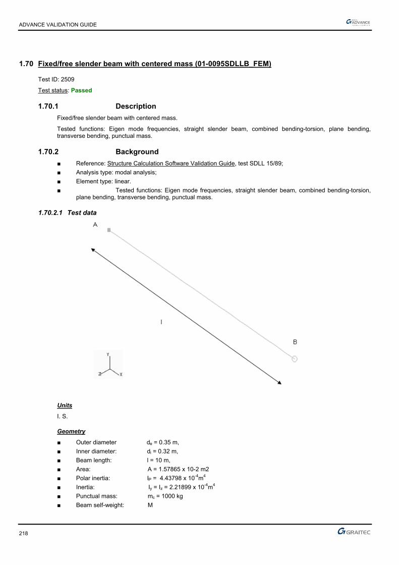
ADVANCE VALIDATION GUIDE
218
1.70 Fixed/free slender beam with centered mass (01-0095SDLLB_FEM)
Test ID: 2509
Test status: Passed
1.70.1 Description
Fixed/free slender beam with centered mass.
Tested functions: Eigen mode frequencies, straight slender beam, combined bending-torsion, plane bending, transverse bending, punctual mass.
1.70.2 Background
■ Reference: Structure Calculation Software Validation Guide, test SDLL 15/89;
■ Analysis type: modal analysis;
■ Element type: linear.
■ Tested functions: Eigen mode frequencies, straight slender beam, combined bending-torsion, plane bending, transverse bending, punctual mass.
1.70.2.1 Test data
Units
I. S.
Geometry
■ Outer diameter de = 0.35 m,
■ Inner diameter: di = 0.32 m,
■ Beam length: l = 10 m,
■ Area: A = 1.57865 x 10⁻² m2
■ Polar inertia: IP = 4.43798 x 10⁻⁴m4
■ Inertia: Iy = Iz = 2.21899 x 10⁻⁴m4
■ Punctual mass: mc = 1000 kg
■ Beam self-weight: M

ADVANCE VALIDATION GUIDE
219
Materials properties
■ Longitudinal elastic modulus: E = 2.1 x 10¹¹ Pa,
■ Density: = 7800 kg/m3
■ Poisson's ratio: =0.3 (this coefficient was not specified in the AFNOR test , the value 0.3 seems to be the more appropriate to obtain the correct frequency value of mode No. 8 with NE/NASTRAN)
Boundary conditions
■ Outer: Fixed at point A, x = 0,
■ Inner: none
Loading
None for the modal analysis
1.70.2.2 Reference results
Reference frequency
For the first mode, the Rayleigh method gives the approximation formula
)M24.0m(I
EI3x2/1f
c3
z1
Mode Shape Units Reference 1 Flexion Hz 1.65 2 Flexion Hz 1.65 3 Flexion Hz 16.07 4 Flexion Hz 16.07 5 Flexion Hz 50.02 6 Flexion Hz 50.02 7 Traction Hz 76.47 8 Torsion Hz 80.47 9 Flexion Hz 103.2 10 Flexion Hz 103.2
Comment: The mass matrix associated with the beam torsion on two nodes, is expressed as:
12/1
2/11
3
Il P
And to the extent that Advance Design uses a condensed mass matrix, the value of the torsion mass inertia
introduced in the model is set to: 3
Il p
Uncertainty about the reference frequencies
■ Analytical solution mode 1
■ Other modes: 1%
Finite elements modeling
■ Linear element AB: Beam
■ Beam meshing: 20 elements.
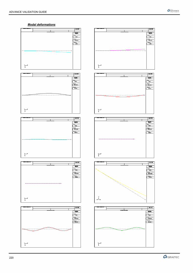
ADVANCE VALIDATION GUIDE
220
Modal deformations
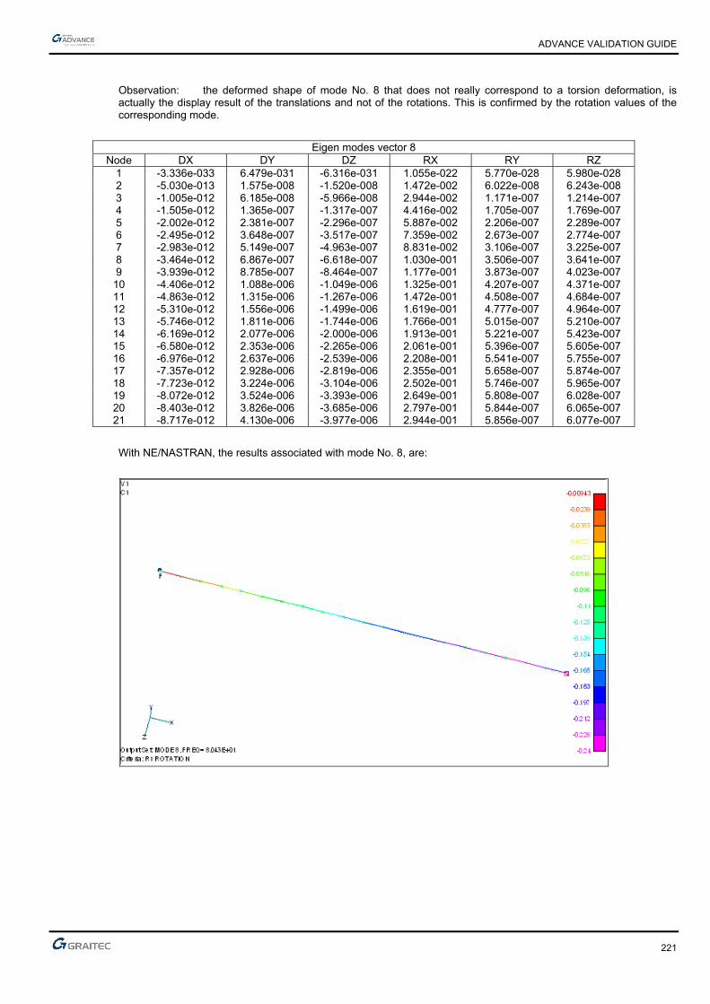
ADVANCE VALIDATION GUIDE
221
Observation: the deformed shape of mode No. 8 that does not really correspond to a torsion deformation, is actually the display result of the translations and not of the rotations. This is confirmed by the rotation values of the corresponding mode.
Eigen modes vector 8
Node DX DY DZ RX RY RZ 1 -3.336e-033 6.479e-031 -6.316e-031 1.055e-022 5.770e-028 5.980e-028 2 -5.030e-013 1.575e-008 -1.520e-008 1.472e-002 6.022e-008 6.243e-008 3 -1.005e-012 6.185e-008 -5.966e-008 2.944e-002 1.171e-007 1.214e-007 4 -1.505e-012 1.365e-007 -1.317e-007 4.416e-002 1.705e-007 1.769e-007 5 -2.002e-012 2.381e-007 -2.296e-007 5.887e-002 2.206e-007 2.289e-007 6 -2.495e-012 3.648e-007 -3.517e-007 7.359e-002 2.673e-007 2.774e-007 7 -2.983e-012 5.149e-007 -4.963e-007 8.831e-002 3.106e-007 3.225e-007 8 -3.464e-012 6.867e-007 -6.618e-007 1.030e-001 3.506e-007 3.641e-007 9 -3.939e-012 8.785e-007 -8.464e-007 1.177e-001 3.873e-007 4.023e-007 10 -4.406e-012 1.088e-006 -1.049e-006 1.325e-001 4.207e-007 4.371e-007 11 -4.863e-012 1.315e-006 -1.267e-006 1.472e-001 4.508e-007 4.684e-007 12 -5.310e-012 1.556e-006 -1.499e-006 1.619e-001 4.777e-007 4.964e-007 13 -5.746e-012 1.811e-006 -1.744e-006 1.766e-001 5.015e-007 5.210e-007 14 -6.169e-012 2.077e-006 -2.000e-006 1.913e-001 5.221e-007 5.423e-007 15 -6.580e-012 2.353e-006 -2.265e-006 2.061e-001 5.396e-007 5.605e-007 16 -6.976e-012 2.637e-006 -2.539e-006 2.208e-001 5.541e-007 5.755e-007 17 -7.357e-012 2.928e-006 -2.819e-006 2.355e-001 5.658e-007 5.874e-007 18 -7.723e-012 3.224e-006 -3.104e-006 2.502e-001 5.746e-007 5.965e-007 19 -8.072e-012 3.524e-006 -3.393e-006 2.649e-001 5.808e-007 6.028e-007 20 -8.403e-012 3.826e-006 -3.685e-006 2.797e-001 5.844e-007 6.065e-007 21 -8.717e-012 4.130e-006 -3.977e-006 2.944e-001 5.856e-007 6.077e-007
With NE/NASTRAN, the results associated with mode No. 8, are:
ADVANCE VALIDATION GUIDE
222
1.70.2.3 Theoretical results
Solver Result name Result description Reference value
CM2 Eigen mode 1 frequency [Hz] 1.65
CM2 Eigen mode 2 frequency [Hz] 1.65
CM2 Eigen mode 3 frequency [Hz] 16.07
CM2 Eigen mode 4 frequency [Hz] 16.07
CM2 Eigen mode 5 frequency [Hz] 50.02
CM2 Eigen mode 6 frequency [Hz] 50.02
CM2 Eigen mode 7 frequency [Hz] 76.47
CM2 Eigen mode 9 frequency [Hz] 103.20
CM2 Eigen mode 10 frequency [Hz] 103.20
Comment: The difference between the reference frequency of torsion mode (mode No. 8) and the one found by Advance Design may be explained by the fact that Advance Design is using a lumped mass matrix (see the corresponding description sheet).
1.70.3 Calculated results
Result name Result description Value Error
Eigen mode 1 frequency [Hz] 1.65 Hz 0.00%
Eigen mode 2 frequency [Hz] 1.65 Hz 0.00%
Eigen mode 3 frequency [Hz] 16.06 Hz -0.06%
Eigen mode 4 frequency [Hz] 16.06 Hz -0.06%
Eigen mode 5 frequency [Hz] 50 Hz -0.04%
Eigen mode 6 frequency [Hz] 50 Hz -0.04%
Eigen mode 7 frequency [Hz] 76.46 Hz -0.01%
Eigen mode 9 frequency [Hz] 103.14 Hz -0.06%
Eigen mode 10 frequency [Hz] 103.14 Hz -0.06%
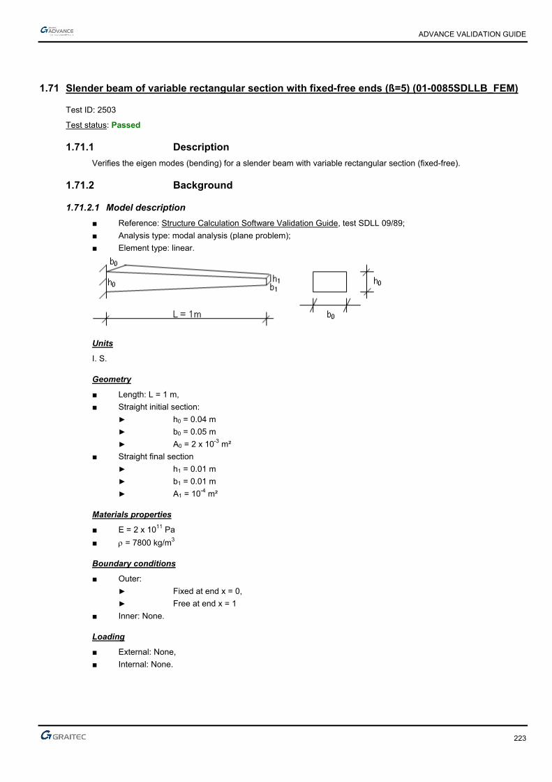
ADVANCE VALIDATION GUIDE
223
1.71 Slender beam of variable rectangular section with fixed-free ends (ß=5) (01-0085SDLLB_FEM)
Test ID: 2503
Test status: Passed
1.71.1 Description
Verifies the eigen modes (bending) for a slender beam with variable rectangular section (fixed-free).
1.71.2 Background
1.71.2.1 Model description
■ Reference: Structure Calculation Software Validation Guide, test SDLL 09/89;
■ Analysis type: modal analysis (plane problem);
■ Element type: linear.
Units
I. S.
Geometry
■ Length: L = 1 m,
■ Straight initial section:
► h0 = 0.04 m
► b0 = 0.05 m
► A0 = 2 x 10⁻³ m²
■ Straight final section
► h1 = 0.01 m
► b1 = 0.01 m
► A1 = 10-4 m²
Materials properties
■ E = 2 x 10¹¹ Pa
■ = 7800 kg/m3
Boundary conditions
■ Outer:
► Fixed at end x = 0,
► Free at end x = 1
■ Inner: None.
Loading
■ External: None,
■ Internal: None.
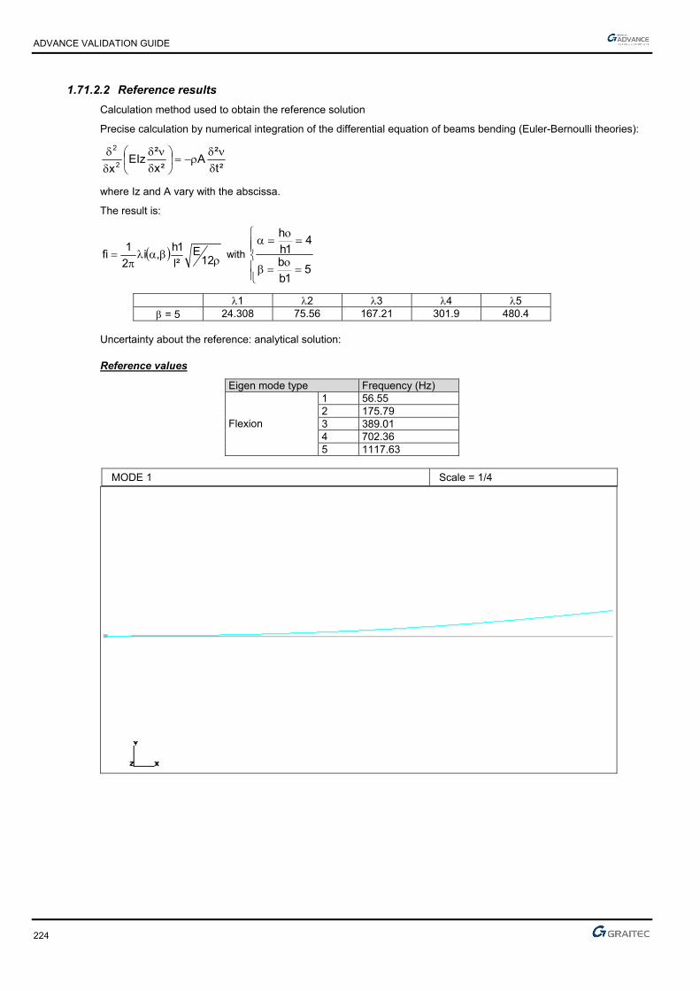
ADVANCE VALIDATION GUIDE
224
1.71.2.2 Reference results
Calculation method used to obtain the reference solution
Precise calculation by numerical integration of the differential equation of beams bending (Euler-Bernoulli theories):
²t
²A
²x
²EIz
x2
2
where Iz and A vary with the abscissa.
The result is:
12E
²l
1h,i
2
1fi with
51b
b
41h
h
1 2 3 4 5 = 5 24.308 75.56 167.21 301.9 480.4
Uncertainty about the reference: analytical solution:
Reference values
Eigen mode type Frequency (Hz) 1 56.55 2 175.79 3 389.01 4 702.36
Flexion
5 1117.63
MODE 1 Scale = 1/4

ADVANCE VALIDATION GUIDE
225
MODE 2 Scale = 1/4
MODE 3 Scale = 1/4

ADVANCE VALIDATION GUIDE
226
MODE 4 Scale = 1/4
MODE 5 Scale = 1/4
ADVANCE VALIDATION GUIDE
227
1.71.2.3 Theoretical results
Theoretical Frequency
Result name Result description Reference value
Eigen mode Frequency of eigen mode 1 [Hz] 56.55
Eigen mode Frequency of eigen mode 2 [Hz] 175.79
Eigen mode Frequency of eigen mode 3 [Hz] 389.01
Eigen mode Frequency of eigen mode 4 [Hz] 702.36
Eigen mode Frequency of eigen mode 5 [Hz] 1117.63
1.71.3 Calculated results
Result name Result description Value Error
Frequency of eigen mode 1 [Hz] 58.49 Hz 3.43%
Frequency of eigen mode 2 [Hz] 177.67 Hz 1.07%
Frequency of eigen mode 3 [Hz] 388.85 Hz -0.04%
Frequency of eigen mode 4 [Hz] 697.38 Hz -0.71%
Frequency of eigen mode 5 [Hz] 1106.31 Hz -1.01%

ADVANCE VALIDATION GUIDE
228
1.72 Cantilever beam in Eulerian buckling with thermal load (01-0092HFLLB_FEM)
Test ID: 2507
Test status: Passed
1.72.1 Description
Verifies the vertical displacement and the normal force on a cantilever beam in Eulerian buckling with thermal load.
1.72.2 Background
1.72.2.1 Model description
■ Reference: Euler theory;
■ Analysis type: Eulerian buckling;
■ Element type: linear.
Units
I. S.
Geometry
■ L= 10 m
■ S=0.01 m2
■ I = 0.0002 m4
Materials properties
■ Longitudinal elastic modulus: E = 2.0 x 10¹⁰ N/m2,
■ Poisson's ratio: = 0.1.
■ Coefficient of thermal expansion: = 0.00001
Boundary conditions
■ Outer: Fixed at end x = 0,
■ Inner: None.
Loading
■ External: Punctual load P = -100000 N at x = L,
■ Internal: T = -50°C (Contraction equivalent to the compression force)
( 5000001.0T0005.001.010.2
100000
ES
N100
)
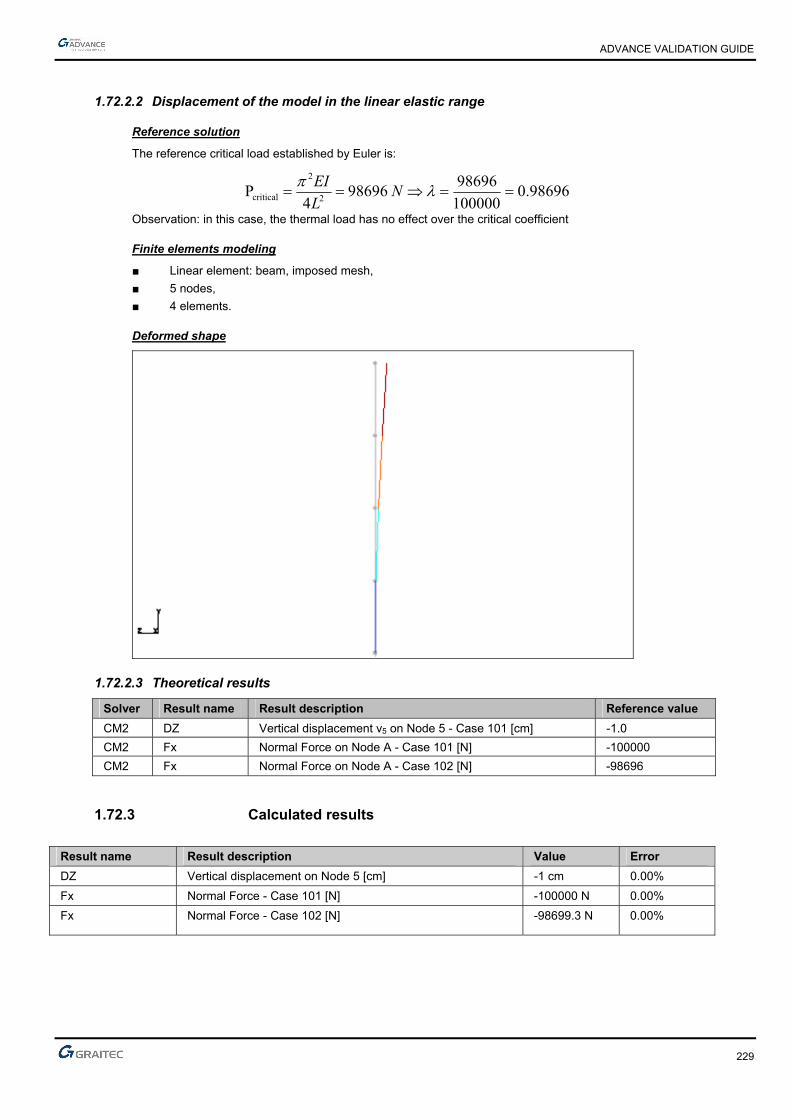
ADVANCE VALIDATION GUIDE
229
1.72.2.2 Displacement of the model in the linear elastic range
Reference solution
The reference critical load established by Euler is:
98696.0100000
98696 98696
4P
2
2
critical N
L
EI
Observation: in this case, the thermal load has no effect over the critical coefficient
Finite elements modeling
■ Linear element: beam, imposed mesh,
■ 5 nodes,
■ 4 elements.
Deformed shape
1.72.2.3 Theoretical results
Solver Result name Result description Reference value
CM2 DZ Vertical displacement v5 on Node 5 - Case 101 [cm] -1.0
CM2 Fx Normal Force on Node A - Case 101 [N] -100000
CM2 Fx Normal Force on Node A - Case 102 [N] -98696
1.72.3 Calculated results
Result name Result description Value Error
DZ Vertical displacement on Node 5 [cm] -1 cm 0.00%
Fx Normal Force - Case 101 [N] -100000 N 0.00%
Fx Normal Force - Case 102 [N] -98699.3 N 0.00%

ADVANCE VALIDATION GUIDE
230
1.73 Simple supported beam in free vibration (01-0098SDLLB_FEM)
Test ID: 2512
Test status: Passed
1.73.1 Description
Simple supported beam in free vibration.
Tested functions: Shear force, eigen frequencies.
1.73.2 Background
■ Reference: NAFEMS, FV5
■ Analysis type: modal analysis;
■ Tested functions: Shear force, eigen frequencies.
1.73.2.1 Problem data
Units
I. S.
Geometry
Full square section:
■ Dimensions: a x b = 2m x 2 m
■ Area: A = 4 m2
■ Inertia: IP = 2.25 m4
Iy = Iz = 1.333 m4

ADVANCE VALIDATION GUIDE
231
Materials properties
■ Longitudinal elastic modulus: E = 2 x 10¹¹ Pa,
■ Poisson's ratio: = 0.3.
■ Density: = 8000 kg/m3
Boundary conditions
■ Outer:
► x = y = z = Rx = 0 at A ;
► y = z =0 at B ;
■ Inner: None.
Loading
None for the modal analysis
1.73.2.2 Reference frequencies
Mode Shape Units Reference 1 Flexion Hz 42.649 2 Flexion Hz 42.649 3 Torsion Hz 77.542 4 Traction Hz 125.00 5 Flexion Hz 148.31 6 Flexion Hz 148.31 7 Torsion Hz 233.10 8 Flexion Hz 284.55 9 Flexion Hz 284.55
Comment: Due to the condensed (lumped) nature of the mass matrix of Advance Design, the frequencies values of 3 and 7 modes cannot be found by this software. The same modeling done with NE/NASTRAN gave respectively for mode 3 and 7: 77.2 and 224.1 Hz.
Finite elements modeling
■ Straight elements: linear element
■ Imposed mesh: 5 meshes

ADVANCE VALIDATION GUIDE
232
Modal deformations
1.73.2.3 Theoretical results
Solver Result name Result description Reference value
CM2 Frequency of eigen mode 1 [Hz] 42.649
CM2 Frequency of eigen mode 2 [Hz] 42.649
CM2 Frequency of eigen mode 3 [Hz] 77.542
CM2 Frequency of eigen mode 4 [Hz] 125.00
CM2 Frequency of eigen mode 5 [Hz] 148.31
CM2 Frequency of eigen mode 6 [Hz] 148.31
CM2 Frequency of eigen mode 7 [Hz] 233.10
Comment: The torsion modes No. 3 and 7 that are calculated with NASTRAN cannot be calculated with Advance Design CM2 solver and therefore the mode No. 3 of the Advance Design analysis corresponds to mode No. 4 of the reference. The same problem in the case of No. 7 - Advance Design, that corresponds to mode No. 8 of the reference.
1.73.3 Calculated results
Result name Result description Value Error
Frequency of eigen mode 1 [Hz] 43.11 Hz 1.08%
Frequency of eigen mode 2 [Hz] 43.11 Hz 1.08%
Frequency of eigen mode 3 [Hz] 124.49 Hz -0.41%
Frequency of eigen mode 4 [Hz] 149.38 Hz 0.72%
Frequency of eigen mode 5 [Hz] 149.38 Hz 0.72%
Frequency of eigen mode 6 [Hz] 269.55 Hz -5.27%
Frequency of eigen mode 7 [Hz] 269.55 Hz -5.27%
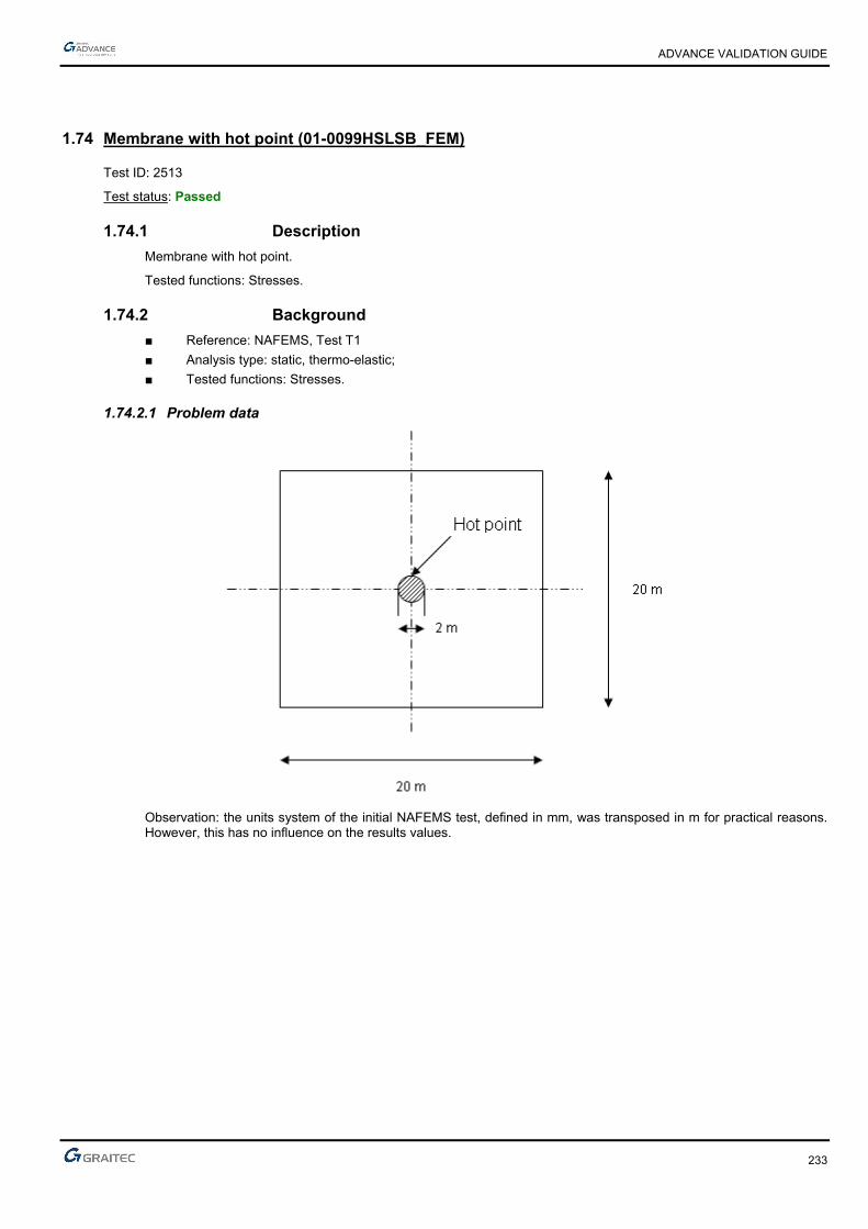
ADVANCE VALIDATION GUIDE
233
1.74 Membrane with hot point (01-0099HSLSB_FEM)
Test ID: 2513
Test status: Passed
1.74.1 Description
Membrane with hot point.
Tested functions: Stresses.
1.74.2 Background
■ Reference: NAFEMS, Test T1
■ Analysis type: static, thermo-elastic;
■ Tested functions: Stresses.
1.74.2.1 Problem data
Observation: the units system of the initial NAFEMS test, defined in mm, was transposed in m for practical reasons. However, this has no influence on the results values.

ADVANCE VALIDATION GUIDE
234
Units
I. S.
Geometry / meshing
A quarter of the structure is modeled by incorporating the terms of symmetries.
Thickness: 1 m
Materials properties
■ Longitudinal elastic modulus: E = 1 x 10¹¹ Pa,
■ Poisson's ratio: = 0.3,
■ Elongation coefficient = 0.00001.
Boundary conditions
■ Outer:
► For all nodes in y = 0, uy =0;
► For all nodes in x = 0, ux =0;
■ Inner: None.
Loading
■ External: None,
■ Internal: Hot point, thermal load T = 100°C;

ADVANCE VALIDATION GUIDE
235
1.74.3 yy stress at point A:
Reference solution:
Reference value: yy = 50 MPa in A
Finite elements modeling
■ Planar elements: membranes,
■ 28 planar elements,
■ 39 nodes.
1.74.3.1 Theoretical results
Solver Result name Result description Reference value
CM2 syy_mid yy in A [MPa] 50
Note: This value (50.87) is obtained with a vertical cross section through point A. The value represents yy at the left end of the diagram.
With CM2, it is essential to display the results with the “Smooth results on planar elements” option deactivated.
1.74.4 Calculated results
Result name Result description Value Error
syy_mid Sigma yy in A [MPa] 50.8666 MPa 1.73%

ADVANCE VALIDATION GUIDE
236
1.75 Double cross with hinged ends (01-0097SDLLB_FEM)
Test ID: 2511
Test status: Passed
1.75.1 Description
Double cross with hinged ends.
Tested functions: Eigen frequencies, crossed beams, in plane bending.
1.75.2 Background
■ Reference: NAFEMS, FV2 test
■ Analysis type: modal analysis;
■ Tested functions: Eigen frequencies, Crossed beams, In plane bending.
1.75.2.1 Problem data
Units
I. S.
Geometry
Full square section:
■ Arm length: L = 5 m
■ Dimensions: a x b = 0.125 x 0.125
■ Area: A = 1.563 10-2 m2
■ Inertia: IP = 3.433 x 10⁻⁵m4
Iy = Iz = 2.035 x 10⁻⁵m4
ADVANCE VALIDATION GUIDE
237
Materials properties
■ Longitudinal elastic modulus: E = 2 x 10¹¹ Pa,
■ Density: = 8000 kg/m3
Boundary conditions
■ Outer: A, B, C, D, E, F, G, H points restraint along x and y;
■ Inner: None.
Loading
None for the modal analysis
1.75.2.2 Reference frequencies
Mode Units Reference 1 Hz 11.336
2,3 Hz 17.709 4 to 8 Hz 17.709
9 Hz 45.345 10,11 Hz 57.390
12 to 16 Hz 57.390
Finite elements modeling
■ Linear elements type: Beam
■ Imposed mesh: 4 Elements / Arms

ADVANCE VALIDATION GUIDE
238
Modal deformations

ADVANCE VALIDATION GUIDE
239
1.75.2.3 Theoretical results
Solver Result name Result description Reference value
CM2 Frequency Frequency of Eigen Mode 1 [Hz] 11.336
CM2 Frequency Frequency of Eigen Mode 2 [Hz] 17.709
CM2 Frequency Frequency of Eigen Mode 3 [Hz] 17.709
CM2 Frequency Frequency of Eigen Mode 4 [Hz] 17.709
CM2 Frequency Frequency of Eigen Mode 5 [Hz] 17.709
CM2 Frequency Frequency of Eigen Mode 6 [Hz] 17.709
CM2 Frequency Frequency of Eigen Mode 7 [Hz] 17.709
CM2 Frequency Frequency of Eigen Mode 8 [Hz] 17.709
CM2 Frequency Frequency of Eigen Mode 9 [Hz] 45.345
CM2 Frequency Frequency of Eigen Mode 10 [Hz] 57.390
CM2 Frequency Frequency of Eigen Mode 11 [Hz] 57.390
CM2 Frequency Frequency of Eigen Mode 12 [Hz] 57.390
CM2 Frequency Frequency of Eigen Mode 13 [Hz] 57.390
CM2 Frequency Frequency of Eigen Mode 14 [Hz] 57.390
CM2 Frequency Frequency of Eigen Mode 15 [Hz] 57.390
CM2 Frequency Frequency of Eigen Mode 16 [Hz] 57.390
1.75.3 Calculated results
Result name Result description Value Error
Frequency of Eigen Mode 1 [Hz] 11.33 Hz -0.05%
Frequency of Eigen Mode 2 [Hz] 17.66 Hz -0.28%
Frequency of Eigen Mode 3 [Hz] 17.66 Hz -0.28%
Frequency of Eigen Mode 4 [Hz] 17.69 Hz -0.11%
Frequency of Eigen Mode 5 [Hz] 17.69 Hz -0.11%
Frequency of Eigen Mode 6 [Hz] 17.69 Hz -0.11%
Frequency of Eigen Mode 7 [Hz] 17.69 Hz -0.11%
Frequency of Eigen Mode 8 [Hz] 17.69 Hz -0.11%
Frequency of Eigen Mode 9 [Hz] 45.02 Hz -0.72%
Frequency of Eigen Mode 10 [Hz] 56.06 Hz -2.32%
Frequency of Eigen Mode 11 [Hz] 56.06 Hz -2.32%
Frequency of Eigen Mode 12 [Hz] 56.34 Hz -1.83%
Frequency of Eigen Mode 13 [Hz] 56.34 Hz -1.83%
Frequency of Eigen Mode 14 [Hz] 56.34 Hz -1.83%
Frequency of Eigen Mode 15 [Hz] 56.34 Hz -1.83%
Frequency of Eigen Mode 16 [Hz] 56.34 Hz -1.83%

ADVANCE VALIDATION GUIDE
240
1.76 Short beam on two hinged supports (01-0084SSLLB_FEM)
Test ID: 2502
Test status: Passed
1.76.1 Description
Verifies the deflection magnitude on a non-slender beam with two hinged supports.
1.76.2 Background
1.76.2.1 Model description
■ Reference: Structure Calculation Software Validation Guide, test SSLL 02/89
■ Analysis type: static linear (plane problem);
■ Element type: linear.
Units
I. S.
Geometry
■ Length: L = 1.44 m,
■ Area: A = 31 x 10-4 m²
■ Inertia: I = 2810 x 10-8 m4
■ Shearing coefficient: az = 2.42 = A/Ar
Materials properties
■ E = 2 x 10¹¹ Pa
■ = 0.3
Boundary conditions
■ Hinge at end x = 0,
■ Hinge at end x = 1.44 m.
Loading
Uniformly distributed force of p = -1. X 105 N/m on beam AB.

ADVANCE VALIDATION GUIDE
241
1.76.2.2 Reference results
Calculation method used to obtain the reference solution
The deflection on the middle of a non-slender beam considering the shear force deformations given by the Timoshenko function:
GA8
pl
EI
pl
384
5v
r
24
where 12
EG and
zr a
AA
where "Ar" is the reduced area and "az" the shear coefficient calculated on the transverse section.
Uncertainty about the reference: analytical solution:
Reference values
Point Magnitudes and units Value C V, deflection (m) -1.25926 x 10⁻³
1.76.2.3 Theoretical results
Solver Result name Result description Reference value
CM2 Dz Deflection magnitude in point C [m] -0.00125926
1.76.3 Calculated results
Result name Result description Value Error
Dz Deflection magnitude in node C [m] -0.00125926 m 0.00%

ADVANCE VALIDATION GUIDE
242
1.77 Double fixed beam in Eulerian buckling with a thermal load (01-0091HFLLB_FEM)
Test ID: 2506
Test status: Passed
1.77.1 Description
Verifies the normal force on the nodes of a double fixed beam in Eulerian buckling with a thermal load.
1.77.2 Background
1.77.2.1 Model description
■ Reference: Euler theory;
■ Analysis type: Eulerian buckling;
■ Element type: linear.
Units
I. S.
Geometry
L= 10 m
Cross Section Sx m² Sy m² Sz m² Ix m4 Iy m4 Iz m4 Vx m3 V1y m3 V1z m3 V2y m3 V2z m3
IPE200 0.002850 0.001400 0.001799 0.0000000646 0.0000014200 0.0000194300 0.00000000 0.00002850 0.00019400 0.00002850 0.00019400
Materials properties
■ Longitudinal elastic modulus: E = 2.1 x 10¹¹ N/m2,
■ Poisson's ratio: = 0.3.
■ Coefficient of thermal expansion: = 0.00001
Boundary conditions
■ Outer: Fixed at end x = 0,
■ Inner: None.
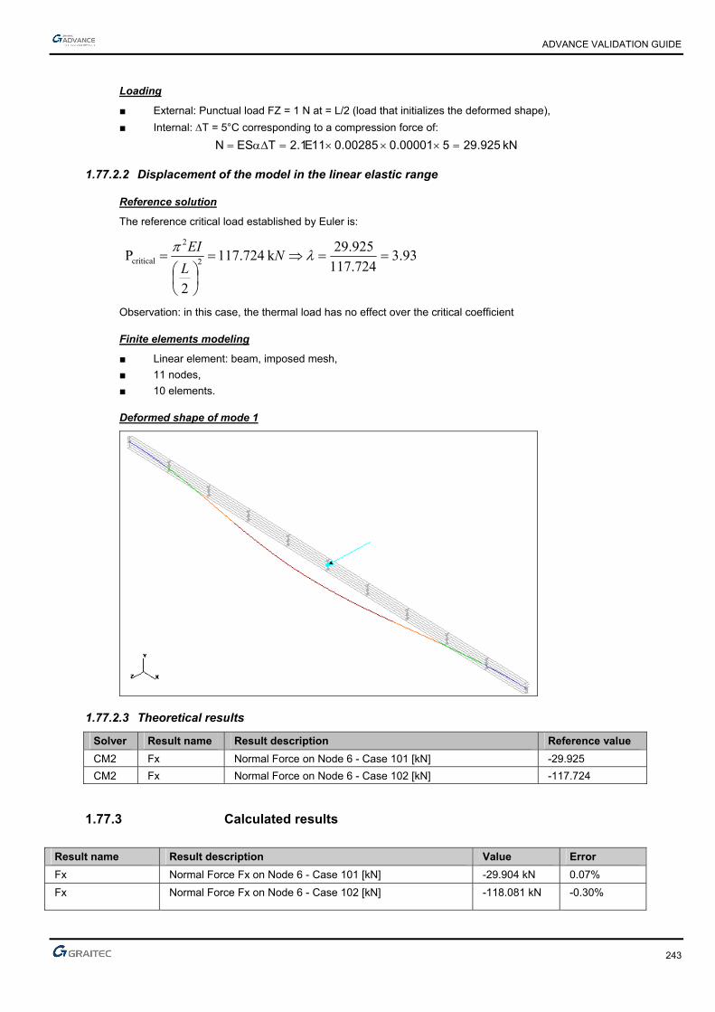
ADVANCE VALIDATION GUIDE
243
Loading
■ External: Punctual load FZ = 1 N at = L/2 (load that initializes the deformed shape),
■ Internal: T = 5°C corresponding to a compression force of:
kN 925.29500001.000285.011E1.2TESN
1.77.2.2 Displacement of the model in the linear elastic range
Reference solution
The reference critical load established by Euler is:
93.3724.117
925.29k 724.117
2
P 2
2
critical
N
L
EI
Observation: in this case, the thermal load has no effect over the critical coefficient
Finite elements modeling
■ Linear element: beam, imposed mesh,
■ 11 nodes,
■ 10 elements.
Deformed shape of mode 1
1.77.2.3 Theoretical results
Solver Result name Result description Reference value
CM2 Fx Normal Force on Node 6 - Case 101 [kN] -29.925
CM2 Fx Normal Force on Node 6 - Case 102 [kN] -117.724
1.77.3 Calculated results
Result name Result description Value Error
Fx Normal Force Fx on Node 6 - Case 101 [kN] -29.904 kN 0.07%
Fx Normal Force Fx on Node 6 - Case 102 [kN] -118.081 kN -0.30%

ADVANCE VALIDATION GUIDE
244
1.78 Fixed/free slender beam with eccentric mass or inertia (01-0096SDLLB_FEM)
Test ID: 2510
Test status: Passed
1.78.1 Description
Fixed/free slender beam with eccentric mass or inertia.
Tested functions: Eigen mode frequencies, straight slender beam, combined bending-torsion, plane bending, transverse bending, punctual mass.
1.78.2 Background
1.78.2.1 Model description
■ Reference: Structure Calculation Software Validation Guide, test SDLL 15/89;
■ Analysis type: modal analysis;
■ Element type: linear.
■ Tested functions: Eigen mode frequencies, straight slender beam, combined bending-torsion, plane bending, transverse bending, punctual mass..
1.78.2.2 Problem data
Units
I. S.
Geometry
■ Outer diameter: de= 0.35 m,
■ Inner diameter: di = 0.32 m,
■ Beam length: l = 10 m,
■ Distance BC: lBC = 1 m
■ Area: A =1.57865 x 10⁻² m2
■ Inertia: Iy = Iz = 2.21899 x 10⁻⁴m4
■ Polar inertia: Ip = 4.43798 x 10⁻⁴m4
■ Punctual mass: mc = 1000 kg

ADVANCE VALIDATION GUIDE
245
Materials properties
■ Longitudinal elasticity modulus of AB element: E = 2.1 x 10¹¹ Pa,
■ Density of the linear element AB: = 7800 kg/m3
■ Poisson's ratio =0.3(this coefficient was not specified in the AFNOR test , the value 0.3 seems to be the more appropriate to obtain the correct frequency value of modes No. 4 and 5 with NE/NASTRAN:
■ Elastic modulus of BC element: E = 1021 Pa
■ Density of the linear element BC: = 0 kg/m3
Boundary conditions
Fixed at point A, x = 0,
Loading
None for the modal analysis
1.78.2.3 Reference frequencies
Reference solutions
The different eigen frequencies are determined using a finite elements model of Euler beam (slender beam).
fz + t0 = flexion x,z + torsion
fy + tr = flexion x,y + traction
Mode Units Reference 1 (fz + t0) Hz 1.636 2 (fy + tr) Hz 1.642 3 (fy + tr) Hz 13.460 4 (fz + t0) Hz 13.590 5 (fz + t0) Hz 28.900 6 (fy + tr) Hz 31.960 7 (fz + t0) Hz 61.610 1 (fz + t0) Hz 63.930
Uncertainty about the reference solutions
The uncertainty about the reference solutions: 1%
Finite elements modeling
■ Linear element AB: Beam
■ Imposed mesh: 50 elements.
■ Linear element BC: Beam
■ Without meshing

ADVANCE VALIDATION GUIDE
246
Modal deformations

ADVANCE VALIDATION GUIDE
247
1.78.2.4 Theoretical results
Solver Result name Result description Reference value
CM2 Frequency Eigen mode 1 frequency (fz + t0) [Hz] 1.636
CM2 Frequency Eigen mode 2 frequency (fy + tr) [Hz] 1.642
CM2 Frequency Eigen mode 3 frequency (fy + tr) [Hz] 13.46
CM2 Frequency Eigen mode 4 frequency (fz + t0) [Hz] 13.59
CM2 Frequency Eigen mode 5 frequency (fz + t0) [Hz] 28.90
CM2 Frequency Eigen mode 6 frequency (fy + tr) [Hz] 31.96
CM2 Frequency Eigen mode 7 frequency (fz + t0) [Hz] 61.61
CM2 Frequency Eigen mode 8 frequency (fy + tr) [Hz] 63.93
Note:
fz + t0 = flexion x,z + torsion
fy + tr = flexion x,y + traction
Observation: because the mass matrix of Advance Design is condensed and not consistent, the torsion modes obtained are not taking into account the self rotation mass inertia of the beam.
1.78.3 Calculated results
Result name Result description Value Error
Eigen mode 1 frequency [Hz] 1.64 Hz 0.24%
Eigen mode 2 frequency [Hz] 1.64 Hz -0.12%
Eigen mode 3 frequency [Hz] 13.45 Hz -0.07%
Eigen mode 4 frequency [Hz] 13.65 Hz 0.44%
Eigen mode 5 frequency [Hz] 29.72 Hz 2.84%
Eigen mode 6 frequency [Hz] 31.96 Hz 0.00%
Eigen mode 7 frequency [Hz] 63.09 Hz 2.40%
Eigen mode 8 frequency [Hz] 63.93 Hz 0.00%

ADVANCE VALIDATION GUIDE
248
1.79 Beam on 3 supports with T/C (k = -10000 N/m) (01-0102SSNLB_FEM)
Test ID: 2516
Test status: Passed
1.79.1 Description
Verifies the rotation, the displacement and the moment on a beam consisting of two elements of the same length and identical characteristics with 3 T/C supports (k = -10000 N/m).
1.79.2 Background
1.79.2.1 Model description
■ Reference: internal GRAITEC test;
■ Analysis type: static non linear;
■ Element type: linear, T/C.
Units
I. S.
Geometry
■ L= 10 m
■ Section: IPE 200, Iz = 0.00001943 m4
Materials properties
■ Longitudinal elastic modulus: E = 2.1 x 10¹¹ N/m2,
■ Poisson's ratio: = 0.3.
Boundary conditions
■ Outer:
► Support at node 1 restrained along x and y (x = 0),
► Support at node 2 restrained along y (x = 10 m),
► T/C ky Rigidity = -10000 N/m (the – sign corresponds to an upwards restraint),
■ Inner: None.
Loading
■ External: Vertical punctual load P = -100 N at x = 5 m,
■ Internal: None.

ADVANCE VALIDATION GUIDE
249
1.79.2.2 References solutions
Displacements
rad 000034.0
Lk2EI3EI32
LkEI6PL
m 00058.0Lk2EI316
PL3v
rad 000106.0Lk2EI3EI16
LkEI3PL
rad 000129.0Lk2EI3EI32
LkEI2PL3
3yzz
3yz
2
3
3yz
3
3
3yzz
3yz
2
2
3yzz
3yz
2
1
Mz Moments
N.m 9.2202
MM
4
PL)m5x(M
N.m 15.58Lk2EI316
PLk3M
0M
1z2zz
3yz
4y
2z
1z
Finite elements modeling
■ Linear element: S beam, automatic mesh,
■ 3 nodes,
■ 2 linear elements + 1 T/C.
Deformed shape

ADVANCE VALIDATION GUIDE
250
Moment diagram
1.79.2.3 Theoretical results
Solver Result name Result description Reference value
CM2 RY Rotation Ry in node 1 [rad] -0.000129
CM2 RY Rotation Ry in node 2 [rad] 0.000106
CM2 DZ Displacement - node 3 [m] 0.00058
CM2 RY Rotation Ry in node 3 [rad] 0.000034
CM2 My M moment - node 1 [Nm] 0
CM2 My M moment - node 2 [Nm] -58.15
CM2 My M moment - middle span 1 [Nm] -220.9
1.79.3 Calculated results
Result name Result description Value Error
RY Rotation Ry in node 1 [rad] 0.000129488 Rad 0.38%
RY Rotation Ry in node 2 [rad] -0.000105646 Rad 0.33%
DZ Displacement - node 3 [m] 0.000581169 m 0.20%
RY Rotation Ry in node 3 [rad] -3.44295e-005 Rad -1.26%
My M moment - node 1 [Nm] 1.77636e-015 N*m 0.00%
My M moment - node 2 [Nm] 58.1169 N*m -0.06%
My M moment - middle span 1 [Nm] -220.942 N*m -0.02%

ADVANCE VALIDATION GUIDE
251
1.80 Linear system of truss beams (01-0103SSLLB_FEM)
Test ID: 2517
Test status: Passed
1.80.1 Description
Verifies the displacement and the normal force for a bar system containing 4 elements of the same length and 2 diagonals.
1.80.2 Background
1.80.2.1 Model description
■ Reference: internal GRAITEC test;
■ Analysis type: static linear;
■ Element type: linear, bar.
Units
I. S.
Geometry
■ L= 5 m
■ Section S = 0.005 m2
Materials properties
Longitudinal elastic modulus: E = 2.1 x 10¹¹ N/m2.
Boundary conditions
■ Outer:
► Support at node 1 restrained along x and y,
► Support at node 2 restrained along x and y,
■ Inner: None.

ADVANCE VALIDATION GUIDE
252
Loading
■ External: Horizontal punctual load P = 50000 N at node 3,
■ Internal: None.
1.80.2.2 References solutions
Displacements
m 000108.0ES11
PL5v
m 000541.0ES11
PL25u
m 000129.0ES11
PL6v
m 000649.0ES11
PL30u
4
4
3
3
N normal forces
N 32141P11
25N N 22727P
11
5N
N 38569P11
26N N 27272P
11
6N
N 22727P11
5N 0N
4243
1323
1412
Finite elements modeling
■ Linear element: bar, without meshing,
■ 4 nodes,
■ 6 linear elements.
Deformed shape

ADVANCE VALIDATION GUIDE
253
Normal forces
1.80.2.3 Theoretical results
Solver Result name Result description Reference value
CM2 DX u3 displacement on Node 3 [m] 0.000649
CM2 DZ v3 displacement on Node 3 [m] -0.000129
CM2 DX u4 displacement on Node 4 [m] 0.000541
CM2 DZ v4 displacement on Node 4 [m] 0.000108
CM2 Fx N12 normal force on Element 1 [N] 0
CM2 Fx N23 normal force on Element 2 [N] -27272
CM2 Fx N43 normal force on Element 3 [N] 22727
CM2 Fx N14 normal force on Element 4 [N] 22727
CM2 Fx N13 normal effort on Element 5 [N] 38569
CM2 Fx N42 normal force on Element 6 [N] -32141
1.80.3 Calculated results
Result name Result description Value Error
DX u3 displacement on Node 3 [m] 0.000649287 m 0.04%
DZ v3 displacement on Node 3 [m] -0.000129871 m -0.68%
DX u4 displacement on Node 4 [m] 0.000541063 m 0.01%
DZ v4 displacement on Node 4 [m] 0.000108224 m 0.21%
Fx N12 normal force on Element 1 [N] 0 N 0.00%
Fx N23 normal force on Element 2 [N] -27272.9 N 0.00%
Fx N43 normal force on Element 3 [N] 22727.1 N 0.00%
Fx N14 normal force on Element 4 [N] 22727.1 N 0.00%
Fx N13 normal effort on Element 5 [N] 38569.8 N 0.00%
Fx N42 normal force on Element 6 [N] -32140.9 N 0.00%

ADVANCE VALIDATION GUIDE
254
1.81 Linear element in combined bending/tension - without compressed reinforcements - Partially tensioned section (02-0158SSLLB_B91)
Test ID: 2520
Test status: Passed
1.81.1 Description
Verifies the reinforcement results for a concrete beam with 8 isostatic spans subjects to uniform loads and compression normal forces.
1.81.1.1 Model description
■ Reference: J. Perchat (CHEC) reinforced concrete course
■ Analysis type: static linear;
■ Element type: planar.
Units
■ Forces: kN
■ Moment: kN.m
■ Stresses: MPa
■ Reinforcement density: cm²
Geometry
■ Beam dimensions: 0.2 x 0.5 ht
■ Length: l = 48 m in 8 spans of 6m,
Materials properties
■ Longitudinal elastic modulus: E = 20000 MPa,
■ Poisson's ratio: = 0.
Boundary conditions
■ Outer:
► Hinged at end x = 0,
► Vertical support at the same level with all other supports
■ Inner: Hinged at each beam end (isostatic)
Loading
■ External:
► Case 1 (DL): uniform linear load g= -5kN/m (on all spans except 8)
Fx = 10 kN at x = 42m: Ng = -10 kN for spans from 6 to 7
Fx = 140 kN at x = 32m: Ng = -150 kN for span 5
Fx = -50 kN at x = 24m: Ng = -100 kN for span 4
Fx = 50 kN at x = 18m: Ng = -50 kN for span 3
Fx = 50 kN at x = 12m: Ng = -100 kN for span 2
Fx = -70 kN at x = 6m: Ng = -30 kN for span 1
► Case 10 (DL): uniform linear load g =
-5 kN/m (span 8)
Fx = 10 kN at x = 48m: Ng = -10 kN
Fx = -10 kN at x = 42m
ADVANCE VALIDATION GUIDE
255
► Case 2 to 8 (LL): uniform linear load q = -9 kN/m (on spans 1, 3 to 7)
uniform linear load q = -15 kN/m (on span 2)
Fx = 30 kN at x = 6m (case 2 span 1)
Fx = -50 kN at x = 6m (case 3 span 2)
Fx = 50 kN at x = 12m (case 3 span 2)
Fx = -40 kN at x = 12m (case 4 span 3)
Fx = 40 kN at x = 18m (case 4 span 3)
Fx = -100 kN at x = 18m (case 5 span 4)
Fx = 100 kN at x = 24m (case 5 span 4)
Fx = -150 kN at x = 24m (case 6 span 5)
Fx = 150 kN at x = 30m (case 6 span 5)
Fx = -8 kN at x = 30m (case 7 span 6)
Fx = 8 kN at x = 36m (case 7 span 6)
Fx = -8 kN at x = 36m (case 8 span 7
Fx = 8 kN at x = 42m (case 8 span 7)
► Case 9 (ACC): uniform linear load a = -25 kN/m (on 8th span)
Fx = 8 kN at x = 36m (case 9 span 8)
Fx = -8 kN at x = 42m (case 9 span 8)
Comb BAELUS: 1.35xDL+1.5xLL with duration of more than 24h (comb 101, 104 to 107)
Comb BAEULI: 1.35xDL+1.5xLL with duration between 1h and 24h (comb 102)
Comb BAELUC: 1.35xDL + 1.5xLL with duration of less than 1h (comb 103)
Comb BAELS: 1xDL + 1*LL (comb 108 to 114)
Comb BAELA: 1xDL + 1xACC with duration of less than 1h (comb 115)
■ Internal: None.
Reinforced concrete calculation hypothesis:
All concrete covers are set to 5 cm
BAEL 91 calculation (according to 99 revised version)
Span Concrete Reinforcement Application Concrete Cracking 1 B20 HA fe500 D>24h No Non
prejudicial 2 B35 Adx fe235 1h<D<24h No Non
prejudicial 3 B50 HA fe 400 D<1h Yes Non
prejudicial 4 B25 HA fe500 D>24h Yes Prejudicial 5 B25 HA fe500 D>24h No Very
prejudicial 6 B30 Adx fe235 D>24h Yes Prejudicial 7 B40 HA fe500 D>24h Yes 160 MPa 8 B45 HA fe500 D<1h Yes Non
prejudicial

ADVANCE VALIDATION GUIDE
256
1.81.1.2 Reinforcement calculation
Reference solution
Span 1 Span 2 Span 3 Span 4 Span 5 Span 6 Span 7 Span 8
fc28 20 35 50 25 25 30 40 45
ft28 1.8 2.7 3.6 2.1 2.1 2.4 3 3.3
fe 500 235 400 500 500 235 500 500
teta 1 0.9 0.85 1 1 1 1 0.85
gamb 1.5 1.5 1.5 1.5 1.5 1.5 1.5 1.15
gams 1.15 1.15 1.15 1.15 1.15 1.15 1.15 1
h 1.6 1 1.6 1.6 1.6 1 1.6 1.6
fbu 11.33 22.04 33.33 14.17 14.17 17.00 22.67 39.13
fed 434.78 204.35 347.83 434.78 434.78 204.35 434.78 500.00
sigpreju 250.00 156.67 264.00 250.00 250.00 156.67 160.00 252.76
sigtpreju 200.00 125.33 211.20 200.00 200.00 125.33 160.00 202.21
g 5.00 5.00 5.00 5.00 5.00 5.00 5.00 5.00
q 9.00 15.00 9.00 9.00 9.00 9.00 9.00 25.00
pu 20.25 29.25 20.25 20.25 20.25 20.25 20.25 30.00
pser 14.00 20.00 14.00 14.00 14.00 14.00 14.00
G -30.00 -100.00 -50.00 -100.00 -150.00 -10.00 -10.00 -10.00
Q -30.00 -50.00 -40.00 -100.00 -100.00 -8.00 -8.00 -8.00
l 6.00 6.00 6.00 6.00 6.00 6.00 6.00 6.00
Mu 91.13 131.63 91.13 91.13 91.13 91.13 91.13 135.00
Nu -85.50 -210.00 -127.50 -285.00 -352.50 -25.50 -25.50 -18.00
Mser 63.00 90.00 63.00 63.00 63.00 63.00 63.00
Nser -60.00 -150.00 -90.00 -200.00 -250.00 -18.00 -18.00
Vu 60.75 87.75 60.75 60.75 60.75 60.75 60.75 90.00
Main reinforcement calculation according to ULS
Mu/A 74.03 89.63 65.63 34.13 20.63 86.03 86.03 131.40
ubu 0.161 0.100 0.049 0.059 0.036 0.125 0.094 0.083
a 0.221 0.133 0.062 0.077 0.046 0.167 0.123 0.108
z 0.410 0.426 0.439 0.436 0.442 0.420 0.428 0.430
Au 6.12 20.57 7.97 8.35 9.18 11.27 5.21 6.46
Main reinforcement calculation with prejudicial cracking according to SLS
Mser/A 51.000 60.000 45.000 23.000 13.000 59.400 59.400 0.000
a 0.4186 0.6678 0.6303 0.4737 0.4737 0.6328 0.6923 0.6157
Mrb 87.53 220.78 302.44 121.16 121.16 182.01 258.82 267.55
A 1.0000 1.0000 1.0000 1.0000 1.0000 1.0000 1.0000 1.0000
B -3.0000 -3.0000 -3.0000 -3.0000 -3.0000 -3.0000 -3.0000 -3.0000
C -0.4533 -0.8511 -0.3788 -0.2044 -0.1156 -0.8426 -0.8250 0.0000
D 0.4533 0.8511 0.3788 0.2044 0.1156 0.8426 0.8250 0.0000
alpha1 0.238 0.432 0.428
z 0.414 0.385 0.386
Aserp 10.22 10.99 10.75

ADVANCE VALIDATION GUIDE
257
Span 1 Span 2 Span 3 Span 4 Span 5 Span 6 Span 7 Span 8
Main reinforcement calculation with very prejudicial cracking according to SLS
Mser/A 51.00 60.00 45.00 23.00 13.00 59.40 59.40 0.00
a 0.47 0.72 0.68 0.53 0.53 0.68 0.69 0.67
Mrb 96.93 231.67 319.66 132.43 132.43 192.27 258.82 283.60
A 1.0000 1.0000 1.0000 1.0000 1.0000 1.0000 1.0000 1.0000
B -3.0000 -3.0000 -3.0000 -3.0000 -3.0000 -3.0000 -3.0000 -3.0000
C -0.5667 -1.0638 -0.4735 -0.2556 -0.1444 -1.0532 -0.8250 0.0000
D 0.5667 1.0638 0.4735 0.2556 0.1444 1.0532 0.8250 0.0000
alpha1 0.203
z 0.420
Asertp 14.049
Transverse reinforcement calculation
tu 0.68 0.98 0.68 0.68 0.68 0.68 0.68 1.00
k 0.57 0.40 0.00 -0.14 -0.41 0.00 0.00 0.00
At/st 1.87 7.08 4.31 3.90 4.77 7.34 3.45 4.44
Recapitulation
Aflex 6.12 20.57 7.97 10.22 14.05 11.27 10.75 6.46
e0 -0.95 -1.67 -1.43 -3.17 -3.97 -0.29 -0.29 -0.13
Aminfsimp 0.75 2.38 1.86 0.87 0.87 2.11 1.24 1.37
Aminfcomp 0.83 2.54 2.01 0.90 0.90 2.80 1.65 0.30
At 1.87 7.08 4.31 3.90 4.77 7.34 3.45 4.44
Atmin 1.60 3.40 2.00 1.60 1.60 3.40 1.60 1.60
Finite elements modeling
■ Linear elements: beams with imposed mesh
■ 29 nodes,
■ 28 linear elements.

ADVANCE VALIDATION GUIDE
258
1.81.1.3 Theoretical results
Solver Result name Result description Reference value
CM2 Az Inf. main reinf. T1 [cm2] 6.12
CM2 Amin Min. main reinf. T1 [cm2] 0.75
CM2 Atz Trans. reinf. T1 [cm2] 1.87
CM2 Az Inf. main reinf. T2 [cm2] 20.57
CM2 Amin Min. main reinf. T2 [cm2] 2.38
CM2 Atz Trans. reinf. T2 [cm2] 7.08
CM2 Az Inf. main reinf. T3 [cm2] 7.97
CM2 Amin Min. main reinf. T3 [cm2] 1.86
CM2 Atz Trans. reinf. T3 [cm2] 4.31
CM2 Az Inf. main reinf. T4 [cm2] 10.22
CM2 Amin Min. main reinf. T4 [cm2] 0.87
CM2 Atz Trans. reinf. T4 [cm2] 3.90
CM2 Az Inf. main reinf. T5 [cm2] 14.05
CM2 Amin Min. main reinf. T5 [cm2] 4.20
CM2 Atz Trans. reinf. T5 [cm2] 4.77
CM2 Az Inf. main reinf. T6 [cm2] 11.27
CM2 Amin Min. main reinf. T6 [cm2] 2.11
CM2 Atz Trans. reinf. T6 [cm2] 7.34
CM2 Az Inf. main reinf. T7 [cm2] 10.75
CM2 Amin Min. main. reinf. T7 [cm2] 1.24
CM2 Atz Trans. reinf. T7 [cm2] 3.45
CM2 Az Inf. main reinf. T8 [cm2] 6.46
CM2 Amin Min. main reinf. T8 [cm2] 1.37
CM2 Atz Trans. reinf. T8 [cm2] 4.44
The "Mu limit" method must be applied in order to achieve the same results.

ADVANCE VALIDATION GUIDE
259
1.81.2 Calculated results
Result name Result description Value Error
Az Inf. main reinf. T1 [cm²] -6.11718 cm² 0.05%
Amin Min. main reinf. T1 [cm²] 0.7452 cm² -0.64%
Atz Trans. reinf. T1 [cm²] 1.8699 cm² -0.01%
Az Inf. main reinf. T2 [cm²] -20.5688 cm² 0.01%
Amin Min. main reinf. T2 [cm²] 2.3783 cm² -0.07%
Atz Trans. reinf. T2 [cm²] 7.07943 cm² -0.01%
Az Inf. main reinf. T3 [cm²] -7.96552 cm² 0.06%
Amin Min. main reinf. T3 [cm²] 1.863 cm² 0.16%
Atz Trans. reinf. T3 [cm²] 4.3125 cm² 0.06%
Az Inf. main reinf. T4 [cm²] -10.2301 cm² -0.10%
Amin Min. main reinf. T4 [cm²] 0.8694 cm² -0.07%
Atz Trans. reinf. T4 [cm²] 3.9008 cm² 0.02%
Az Inf. main reinf. T5 [cm²] -14.0512 cm² -0.01%
Amin Min. main reinf. T5 [cm²] 4.2 cm² 0.00%
Atz Trans. reinf. T5 [cm²] 4.7702 cm² 0.00%
Az Inf. main reinf. T6 [cm²] -11.2742 cm² -0.04%
Amin Min. main reinf. T6 [cm²] 2.11404 cm² 0.19%
Atz Trans. reinf. T6 [cm²] 7.34043 cm² 0.01%
Az Inf. main reinf. T7 [cm²] -10.7634 cm² -0.12%
Amin Min. main. reinf. T7 [cm²] 1.242 cm² 0.16%
Atz Trans. reinf. T7 [cm²] 3.45 cm² 0.00%
Az Inf. main reinf. T8 [cm²] -6.47718 cm² -0.27%
Amin Min. main reinf. T8 [cm²] 1.3662 cm² -0.28%
Atz Trans. reinf. T8 [cm²] 4.44444 cm² 0.10%

ADVANCE VALIDATION GUIDE
260
1.82 Linear element in simple bending - without compressed reinforcement (02-0162SSLLB_B91)
Test ID: 2521
Test status: Passed
1.82.1 Description
Verifies the reinforcement results for a concrete beam with 8 isostatic spans subjected to uniform loads.
1.82.1.1 Model description
■ Reference: J. Perchat (CHEC) reinforced concrete course
■ Analysis type: static linear;
■ Element type: planar.
Units
■ Forces: kN
■ Moment: kN.m
■ Stresses: MPa
■ Reinforcement density: cm2
Geometry
■ Beam dimensions: 0.2 x 0.5 ht
■ Length: l = 42 m in 7 spans of 6m,
Materials properties
■ Longitudinal elastic modulus: E = 20000 MPa,
■ Poisson's ratio: = 0.
Boundary conditions
■ Outer:
► Hinged at end x = 0,
► Vertical support at the same level with all other supports
■ Inner: Hinge z at each beam end (isostatic)
Loading
■ External:
► Case 1 (DL): uniform linear load g = -5 kN/m (on all spans except 8)
► Case 2 to 8 (LL): uniform linear load q = -9 kN/m (on spans 1, 3 to 7)
uniform linear load q = -15 kN/m (on span 2)
► Case 9 (ACC): uniform linear load a = -25 kN/m (on 8th span)
► Case 10 (DL): uniform linear load g = -5 kN/m (on 8th span)
Comb BAELUS: 1.35xDL+1.5xLL with duration of more than 24h (comb 101, 104 to 107)
Comb BAEULI: 1.35xDL+1.5xLL with duration between 1h and 24h (comb 102)
Comb BAELUC: 1.35xDL + 1.5xLL with duration of less than 1h (comb 103)
Comb BAELS: 1xDL + 1*LL (comb 108 to 114)
Comb BAELUA: 1xDL + 1xACC (comb 115)
■ Internal: None.
ADVANCE VALIDATION GUIDE
261
Reinforced concrete calculation hypothesis:
■ All concrete covers are set to 5 cm
■ BAEL 91 calculation with the revised version 99
Span Concrete Reinforcement Application Concrete Cracking 1 B20 HA fe500 D>24h No Non
prejudicial 2 B35 Adx fe235 1h<D<24h No Non
prejudicial 3 B50 HA fe 400 D<1h Yes Non
prejudicial 4 B25 HA fe500 D>24h Yes Prejudicial 5 B60 HA fe500 D>24h No Very
prejudicial 6 B30 Adx fe235 D>24h Yes Prejudicial 7 B40 HA fe500 D>24h Yes 160 MPa 8 B45 HA fe500 D<1h Yes Non
prejudicial
1.82.1.2 Reinforcement calculation
Reference solution
Span 1 Span 2 Span 3 Span 4 Span 5 Span 6 Span 7 Span 8 fc28 20 35 50 25 60 30 40 45 ft28 1.8 2.7 3.6 2.1 4.2 2.4 3 3.3 fe 500 235 400 500 500 235 500 500
teta 1 0.9 0.85 1 1 1 1 0.85 gamb 1.5 1.5 1.5 1.5 1.5 1.5 1.5 1.15 gams 1.15 1.15 1.15 1.15 1.15 1.15 1.15 1
h 1.6 1 1.6 1.6 1.6 1 1.6 1.6
fbu 11.33 22.04 33.33 14.17 34.00 17.00 22.67 39.13 fed 434.78 204.35 347.83 434.78 434.78 204.35 434.78 500.00
sigpreju 250.00 156.67 264.00 250.00 285.15 156.67 160.00 252.76 sigtpreju 200.00 125.33 211.20 200.00 228.12 125.33 160.00 202.21
g 5.00 5.00 5.00 5.00 5.00 5.00 5.00 5.00 q 9.00 15.00 9.00 9.00 9.00 9.00 9.00 25.00
pu 20.25 29.25 20.25 20.25 20.25 20.25 20.25 30.00 pser 14.00 20.00 14.00 14.00 14.00 14.00 14.00
l 6.00 6.00 6.00 6.00 6.00 6.00 6.00 6.00 Mu 91.13 131.63 91.13 91.13 91.13 91.13 91.13 135.00
Mser 63.00 90.00 63.00 63.00 63.00 63.00 63.00 Vu 60.75 87.75 60.75 60.75 60.75 60.75 60.75 90.00
Longitudinal reinforcement calculation according to ELU ubu 0.199 0.147 0.068 0.159 0.066 0.132 0.099 0.085 a 0.279 0.200 0.087 0.217 0.086 0.178 0.131 0.111 z 0.400 0.414 0.434 0.411 0.435 0.418 0.426 0.430
Au 5.24 15.56 6.03 5.10 4.82 10.67 4.91 6.28 Main reinforcement calculation with prejudicial cracking according to SLS
A 1.000 1.000 1.000 1.000 1.000 1.000 1.000 1.000 B -3.000 -3.000 -3.000 -3.000 -3.000 -3.000 -3.000 -3.000 C -0.56000 -0.89362 -0.87500 D 0.56000 0.89362 0.87500
alpha1 0.367 0.442 0.438 z 0.395 0.384 0.384
Aserp 6.38 10.48 10.25 Main reinforcement calculation with very prejudicial cracking according to SLS
A 1.00 1.00 1.00 1.00 1.00 1.00 1.00 1.00 B -3.00 -3.00 -3.00 -3.00 -3.00 -3.00 -3.00 -3.00 C -0.70 -1.60 -0.66 -0.70 -0.61371 -1.12 -0.88 0.00 D 0.70 1.60 0.66 0.70 0.61371 1.12 0.88 0.00
alpha1 0.381 z 0.393
Asertp 7.030

ADVANCE VALIDATION GUIDE
262
Span 1 Span 2 Span 3 Span 4 Span 5 Span 6 Span 7 Span 8 Transversal reinforcement calculation
tu 0.68 0.98 0.68 0.68 0.68 0.68 0.68 1.00 k 1.00 1.00 0.00 0.00 0.00 0.00 0.00 0.00
At/st 0.69 1.79 4.31 3.45 3.45 7.34 3.45 4.44 Recapitulation
Aflex 5.24 15.56 6.03 6.38 7.03 10.67 10.25 6.28 Aminflex 0.75 2.38 1.86 0.87 1.74 2.11 1.24 1.37
At 0.69 1.79 4.31 3.45 3.45 7.34 3.45 4.44 Atmin 1.60 3.40 2.00 1.60 1.60 3.40 1.60 1.60
Finite elements modeling
■ Linear elements: beams with imposed mesh
■ 29 nodes,
■ 28 linear elements.
1.82.1.3 Theoretical results
Reference
Solver Result name Result description Reference value
CM2 Az Inf. main reinf. T1 [cm2] 5.24
CM2 Amin Min. main reinf. T1 [cm2] 0.75
CM2 Atz Trans. reinf. T1 [cm2] 0.69
CM2 Az Inf. main reinf. T2 [cm2] 15.56
CM2 Amin Min. main reinf. T2 [cm2] 2.38
CM2 Atz Trans. reinf. T2 [cm2] 1.79
CM2 Az Inf. main reinf. T3 [cm2] 6.03
CM2 Amin Min. main reinf. T3 [cm2] 1.86
CM2 Atz Trans. reinf. T3 [cm2] 4.31
CM2 Az Inf. main reinf. T4 [cm2] 6.38
CM2 Amin Min. main reinf. T4 [cm2] 0.87
CM2 Atz Trans. reinf. T4 [cm2] 3.45
CM2 Az Inf. main reinf. T5 [cm2] 7.03
CM2 Amin Min. main reinf. T5 [cm2] 1.74
CM2 Atz Trans. reinf. T5 [cm2] 3.45
CM2 Az Inf. main reinf. T6 [cm2] 10.67
CM2 Amin Min. main reinf. T6 [cm2] 2.11
CM2 Atz Trans. reinf. T6 [cm2] 7.34
CM2 Az Inf. main reinf. T7 [cm2] 10.25
CM2 Amin Min. main. reinf. T7 [cm2] 1.24
CM2 Atz Trans. reinf. T7 [cm2] 3.45
CM2 Az Inf. main reinf. T8 [cm2] 6.28
CM2 Amin Min. main reinf. T8 [cm2] 1.37
CM2 Atz Trans. reinf. T8 [cm2] 4.44
The "Mu limit" method must be applied to attain the same results.

ADVANCE VALIDATION GUIDE
263
1.82.2 Calculated results
Result name Result description Value Error
Az Inf. main reinf. T1 [cm²] -5.24348 cm² -0.07%
Amin Min. main reinf. T1 [cm²] 0.7452 cm² -0.64%
Atz Trans. reinf. T1 [cm²] 0.69 cm² 0.00%
Az Inf. main reinf. T2 [cm²] -15.5613 cm² -0.01%
Amin Min. main reinf. T2 [cm²] 2.3783 cm² -0.07%
Atz Trans. reinf. T2 [cm²] 1.79433 cm² 0.24%
Az Inf. main reinf. T3 [cm²] -6.03286 cm² -0.05%
Amin Min. main reinf. T3 [cm²] 1.863 cm² 0.16%
Atz Trans. reinf. T3 [cm²] 4.3125 cm² 0.06%
Az Inf. main reinf. T4 [cm²] -6.38336 cm² -0.05%
Amin Min. main reinf. T4 [cm²] 0.8694 cm² -0.07%
Atz Trans. reinf. T4 [cm²] 3.45 cm² 0.00%
Az Inf. main reinf. T5 [cm²] -7.03527 cm² -0.07%
Amin Min. main reinf. T5 [cm²] 1.7388 cm² -0.07%
Atz Trans. reinf. T5 [cm²] 3.45 cm² 0.00%
Az Inf. main reinf. T6 [cm²] -10.6698 cm² 0.00%
Amin Min. main reinf. T6 [cm²] 2.11404 cm² 0.19%
Atz Trans. reinf. T6 [cm²] 7.34043 cm² 0.01%
Az Inf. main reinf. T7 [cm²] -10.2733 cm² -0.23%
Amin Min. main. reinf. T7 [cm²] 1.242 cm² 0.16%
Atz Trans. reinf. T7 [cm²] 3.45 cm² 0.00%
Az Inf. main reinf. T8 [cm²] -6.29338 cm² -0.21%
Amin Min. main reinf. T8 [cm²] 1.3662 cm² -0.28%
Atz Trans. reinf. T8 [cm²] 4.44444 cm² 0.10%

ADVANCE VALIDATION GUIDE
264
1.83 Beam on 3 supports with T/C (k -> infinite) (01-0101SSNLB_FEM)
Test ID: 2515
Test status: Passed
1.83.1 Description
Verifies the rotation, the displacement and the moment on a beam consisting of two elements of the same length and identical characteristics with 3 T/C supports (k -> infinite).
1.83.2 Background
1.83.2.1 Model description
■ Reference: internal GRAITEC test;
■ Analysis type: static non linear;
■ Element type: linear, T/C.
Units
I. S.
Geometry
■ L= 10 m
■ Section: IPE 200, Iz = 0.00001943 m4
Materials properties
■ Longitudinal elastic modulus: E = 2.1 x 10¹¹ N/m2,
■ Poisson's ratio: = 0.3.
Boundary conditions
■ Outer:
► Support at node 1 restrained along x and y (x = 0),
► Support at node 2 restrained along y (x = 10 m),
► T/C stiffness ky (1.1030N/m),
■ Inner: None.
Loading
■ External: Vertical punctual load P = -100 N at x = 5 m,
■ Internal: None.
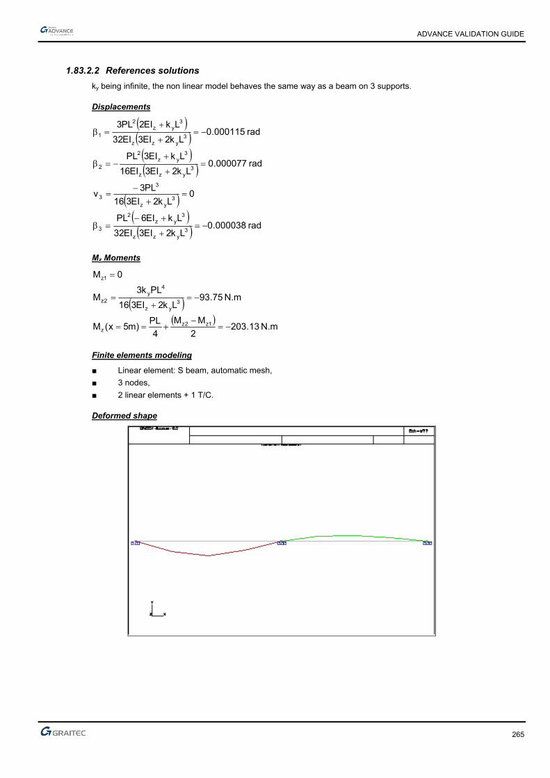
ADVANCE VALIDATION GUIDE
265
1.83.2.2 References solutions
ky being infinite, the non linear model behaves the same way as a beam on 3 supports.
Displacements
rad 000038.0
Lk2EI3EI32
LkEI6PL
0Lk2EI316
PL3v
rad 000077.0Lk2EI3EI16
LkEI3PL
rad 000115.0Lk2EI3EI32
LkEI2PL3
3yzz
3yz
2
3
3yz
3
3
3yzz
3yz
2
2
3yzz
3yz
2
1
Mz Moments
N.m 13.2032
MM
4
PL)m5x(M
N.m 75.93Lk2EI316
PLk3M
0M
1z2zz
3yz
4y
2z
1z
Finite elements modeling
■ Linear element: S beam, automatic mesh,
■ 3 nodes,
■ 2 linear elements + 1 T/C.
Deformed shape
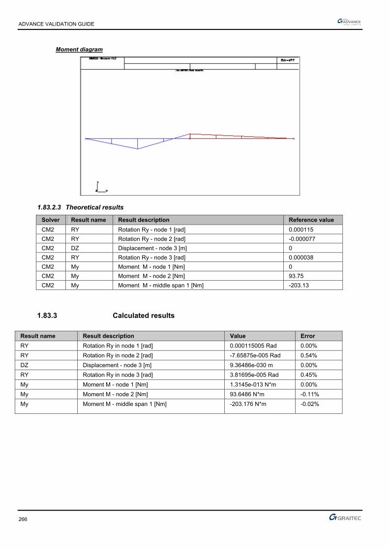
ADVANCE VALIDATION GUIDE
266
Moment diagram
1.83.2.3 Theoretical results
Solver Result name Result description Reference value
CM2 RY Rotation Ry - node 1 [rad] 0.000115
CM2 RY Rotation Ry - node 2 [rad] -0.000077
CM2 DZ Displacement - node 3 [m] 0
CM2 RY Rotation Ry - node 3 [rad] 0.000038
CM2 My Moment M - node 1 [Nm] 0
CM2 My Moment M - node 2 [Nm] 93.75
CM2 My Moment M - middle span 1 [Nm] -203.13
1.83.3 Calculated results
Result name Result description Value Error
RY Rotation Ry in node 1 [rad] 0.000115005 Rad 0.00%
RY Rotation Ry in node 2 [rad] -7.65875e-005 Rad 0.54%
DZ Displacement - node 3 [m] 9.36486e-030 m 0.00%
RY Rotation Ry in node 3 [rad] 3.81695e-005 Rad 0.45%
My Moment M - node 1 [Nm] 1.3145e-013 N*m 0.00%
My Moment M - node 2 [Nm] 93.6486 N*m -0.11%
My Moment M - middle span 1 [Nm] -203.176 N*m -0.02%
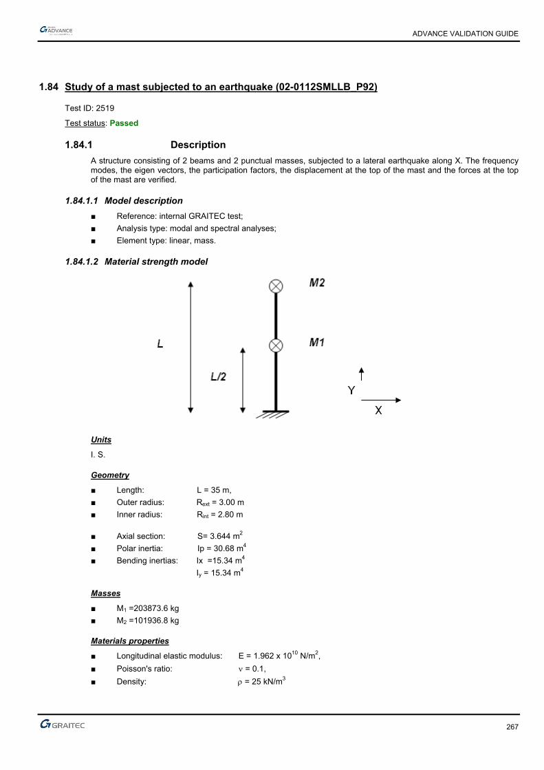
ADVANCE VALIDATION GUIDE
267
1.84 Study of a mast subjected to an earthquake (02-0112SMLLB_P92)
Test ID: 2519
Test status: Passed
1.84.1 Description
A structure consisting of 2 beams and 2 punctual masses, subjected to a lateral earthquake along X. The frequency modes, the eigen vectors, the participation factors, the displacement at the top of the mast and the forces at the top of the mast are verified.
1.84.1.1 Model description
■ Reference: internal GRAITEC test;
■ Analysis type: modal and spectral analyses;
■ Element type: linear, mass.
1.84.1.2 Material strength model
Units
I. S.
Geometry
■ Length: L = 35 m,
■ Outer radius: Rext = 3.00 m
■ Inner radius: Rint = 2.80 m
■ Axial section: S= 3.644 m2
■ Polar inertia: Ip = 30.68 m4
■ Bending inertias: Ix =15.34 m4
Iy = 15.34 m4
Masses
■ M1 =203873.6 kg
■ M2 =101936.8 kg
Materials properties
■ Longitudinal elastic modulus: E = 1.962 x 10¹⁰ N/m2,
■ Poisson's ratio: = 0.1,
■ Density: = 25 kN/m3
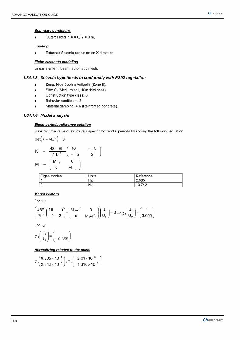
ADVANCE VALIDATION GUIDE
268
Boundary conditions
■ Outer: Fixed in X = 0, Y = 0 m,
Loading
■ External: Seismic excitation on X direction
Finite elements modeling
Linear element: beam, automatic mesh,
1.84.1.3 Seismic hypothesis in conformity with PS92 regulation
■ Zone: Nice Sophia Antipolis (Zone II).
■ Site: S1 (Medium soil, 10m thickness).
■ Construction type class: B
■ Behavior coefficient: 3
■ Material damping: 4% (Reinforced concrete).
1.84.1.4 Modal analysis
Eigen periods reference solution
Substract the value of structure’s specific horizontal periods by solving the following equation:
0MKdet 2
2
1
3
M0
0MM
25
516
L7
EI48K
Eigen modes Units Reference 1 Hz 2.085 2 Hz 10.742
Modal vectors
For 1:
055.3
1
U
U0
U
U
M0
0M
25
516
L7
EI48
2
11
2
1
12
2
211
3
For 2:
655.0
1
U
U
2
12
Normalizing relative to the mass
3
4
110842.2
10305.9 ;
3
3
210316.1
1001.2
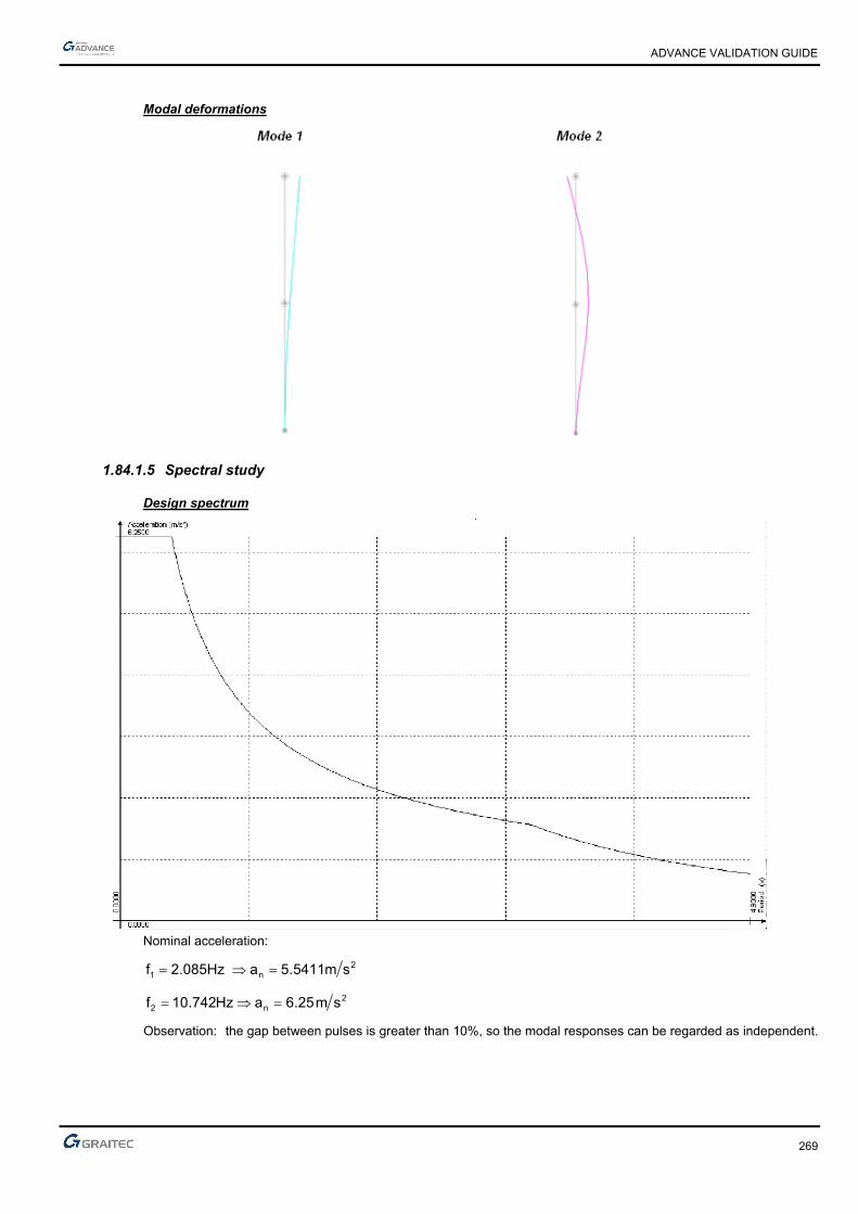
ADVANCE VALIDATION GUIDE
269
Modal deformations
1.84.1.5 Spectral study
Design spectrum
Nominal acceleration:
2n1 sm5411.5a 2.085Hzf
2n2 sm25.6aHz742.01f
Observation: the gap between pulses is greater than 10%, so the modal responses can be regarded as independent.

ADVANCE VALIDATION GUIDE
270
Reference participation factors
Mii
séismedudirectionladedirecteurVecteur:
Eigen modes Reference 1 479.427 2 275.609
Pseudo-acceleration
iiii a in (m/s2)
4.0%5
: Damping correction factor.
: Structure damping.
8.2556
2.70261
2.4783-
3.78521
Reference modal displacement
024.814E
021.576E1
045.446E-
048.318E2
Equivalent static forces
058.415E
055.510EF1
052.526E-
057.717EF2
Displacement at the top of the mast
221 04E446.502E81.4U
Units Reference m 4.814 E-02
Shear force at the top of the mast
3
05E526.205E415.8T
22
1
3: Being the behavior coefficient of forces
Units Reference N 2.929 E+05
Moment at the base
Units Reference N.m 1.578 E+07

ADVANCE VALIDATION GUIDE
271
1.84.1.6 Theoretical results
Reference
Solver Result name Result description Reference value
CM2 Frequency Frequency Mode 1 [Hz] 2.085
CM2 Frequency Frequency Mode 2 [Hz] 10.742
CM2 D Displacement at the top of the mast [cm] 4.814
CM2 Fz Forces at the top of the mast [N] 2.929E+05
1.84.2 Calculated results
Result name Result description Value Error
Frequency Mode 1 [Hz] 2.08 Hz -0.24%
Frequency Mode 2 [Hz] 10.74 Hz -0.02%
D Displacement at the top of the mast [cm] 4.81159 cm -0.05%
Fz Forces at the top of the mast [N] 292677 N -0.08%

ADVANCE VALIDATION GUIDE
272
1.85 Design of a concrete floor with an opening (03-0208SSLLG_BAEL91)
Test ID: 2524
Test status: Passed
1.85.1 Description
Verifies the displacements, bending moments and reinforcement results for a 2D concrete slab with supports and punctual loads.
1.85.2 Background
1.85.2.1 Model description
■ Calculation model: 2D concrete slab.
► Slab thickness: 20 cm
► Slab length: 20m
► Slab width: 10m
► The supports (punctual and linear) are considered as hinged.
► Supports positioning (see scheme below)
► 1,50m*2,50m opening => see positioning on the following scheme
■ Materials:
► Concrete B25
► Young module: E= 36000 MPa
■ Load case:
► Permanent loads: 100 kg/m2
► Permanent loads: 200 kg/ml around the opening
► Punctual loads of 2T in permanent loads (see the following definition)
► Usage overloads: 250 kg/m2
■ Mesh density: 0.5 m
Slab geometry
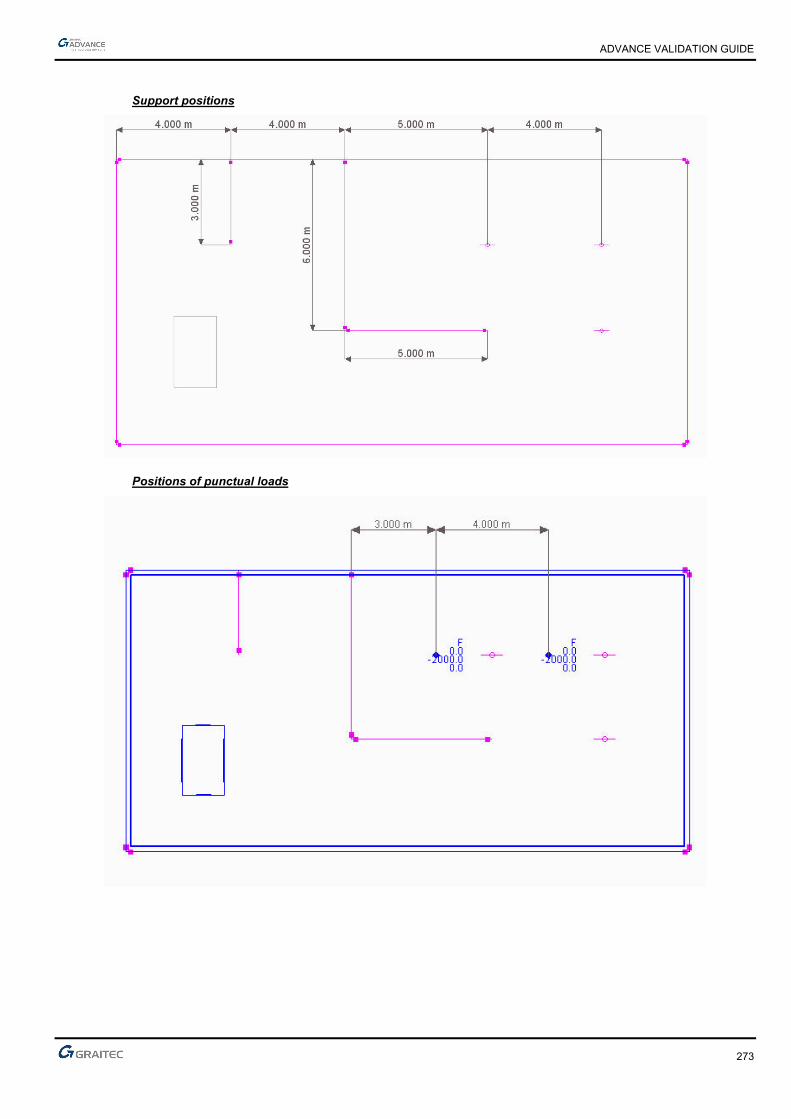
ADVANCE VALIDATION GUIDE
273
Support positions
Positions of punctual loads
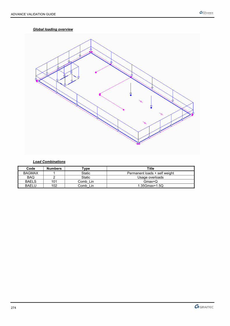
ADVANCE VALIDATION GUIDE
274
Global loading overview
Load Combinations
Code Numbers Type Title BAGMAX 1 Static Permanent loads + self weight
BAQ 2 Static Usage overloads BAELS 101 Comb_Lin Gmax+Q BAELU 102 Comb_Lin 1.35Gmax+1.5Q
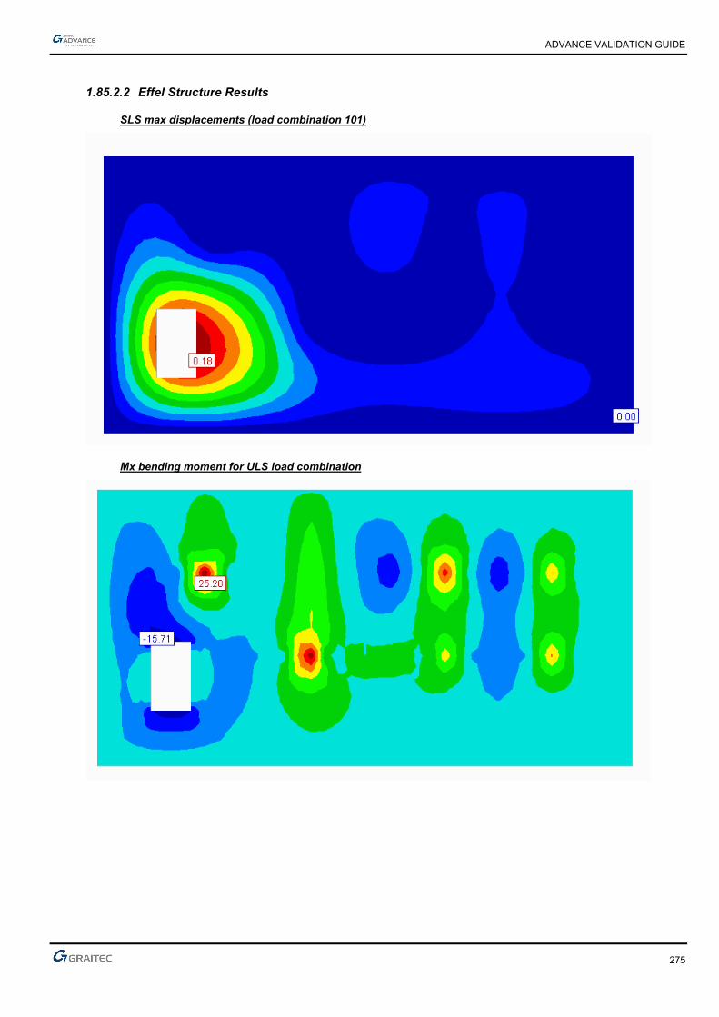
ADVANCE VALIDATION GUIDE
275
1.85.2.2 Effel Structure Results
SLS max displacements (load combination 101)
Mx bending moment for ULS load combination

ADVANCE VALIDATION GUIDE
276
My bending moment for ULS load combination
Mxy bending moment for ULS load combination
1.85.2.3 Effel RC Expert Results
Main hypothesis
■ Top and bottom concrete covers: 3 cm
■ Slightly dangerous cracking
■ Concrete B25 => Fc28= 25 MPa
■ Reinforcement calculation according to Wood method.
■ Calculation starting from non averaged forces.
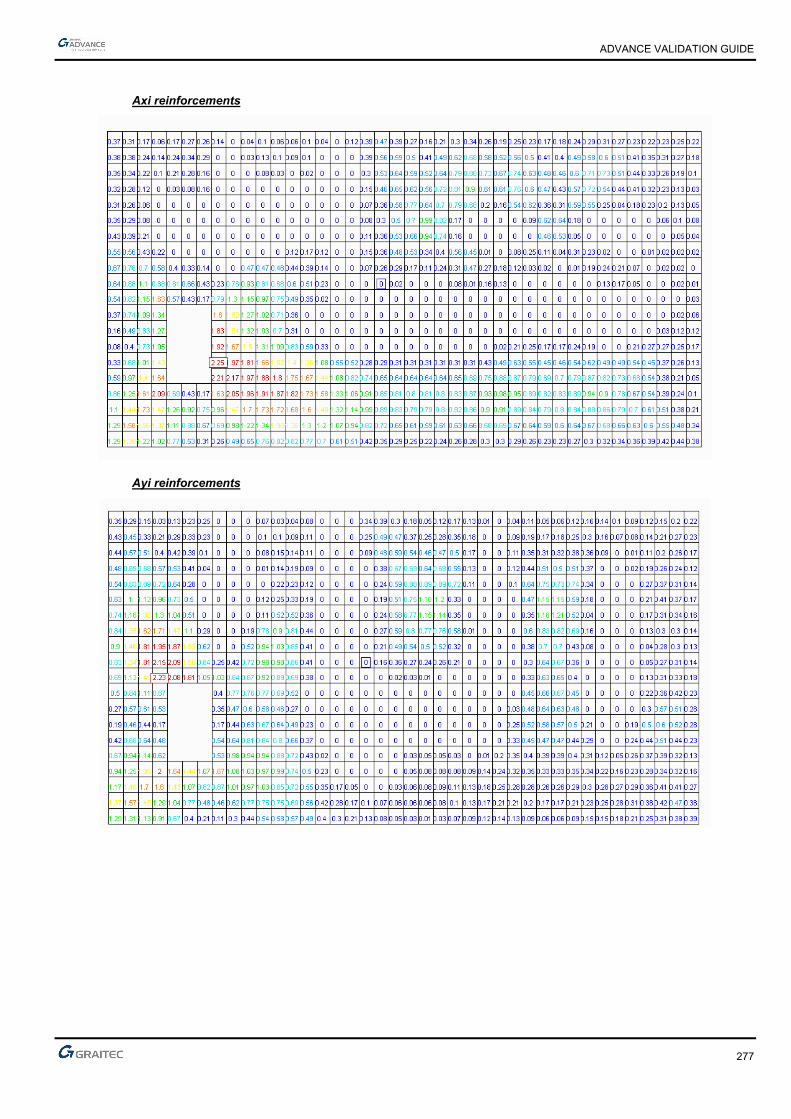
ADVANCE VALIDATION GUIDE
277
Axi reinforcements
Ayi reinforcements
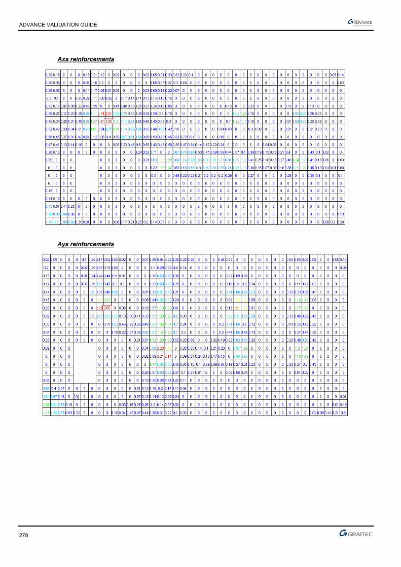
ADVANCE VALIDATION GUIDE
278
Axs reinforcements
Ays reinforcements
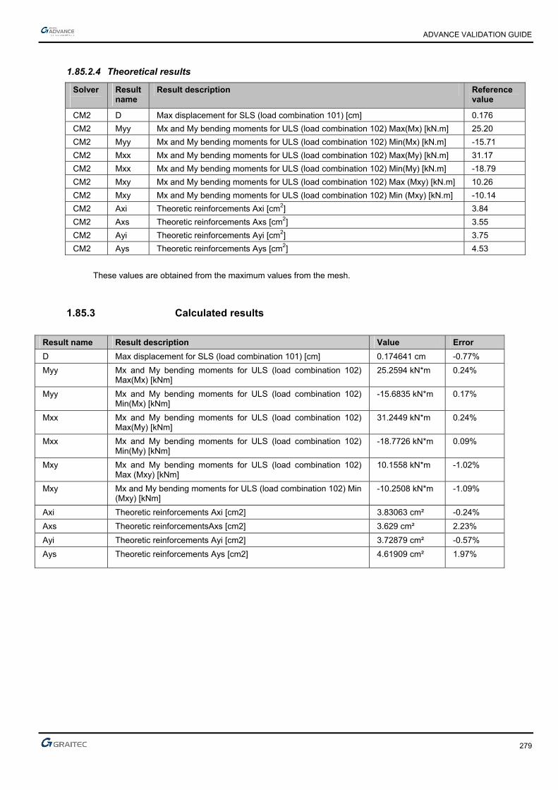
ADVANCE VALIDATION GUIDE
279
1.85.2.4 Theoretical results
Solver
Result name
Result description Reference value
CM2 D Max displacement for SLS (load combination 101) [cm] 0.176
CM2 Myy Mx and My bending moments for ULS (load combination 102) Max(Mx) [kN.m] 25.20
CM2 Myy Mx and My bending moments for ULS (load combination 102) Min(Mx) [kN.m] -15.71
CM2 Mxx Mx and My bending moments for ULS (load combination 102) Max(My) [kN.m] 31.17
CM2 Mxx Mx and My bending moments for ULS (load combination 102) Min(My) [kN.m] -18.79
CM2 Mxy Mx and My bending moments for ULS (load combination 102) Max (Mxy) [kN.m] 10.26
CM2 Mxy Mx and My bending moments for ULS (load combination 102) Min (Mxy) [kN.m] -10.14
CM2 Axi Theoretic reinforcements Axi [cm2] 3.84
CM2 Axs Theoretic reinforcements Axs [cm2] 3.55
CM2 Ayi Theoretic reinforcements Ayi [cm2] 3.75
CM2 Ays Theoretic reinforcements Ays [cm2] 4.53
These values are obtained from the maximum values from the mesh.
1.85.3 Calculated results
Result name Result description Value Error
D Max displacement for SLS (load combination 101) [cm] 0.174641 cm -0.77%
Myy Mx and My bending moments for ULS (load combination 102) Max(Mx) [kNm]
25.2594 kN*m 0.24%
Myy Mx and My bending moments for ULS (load combination 102) Min(Mx) [kNm]
-15.6835 kN*m 0.17%
Mxx Mx and My bending moments for ULS (load combination 102) Max(My) [kNm]
31.2449 kN*m 0.24%
Mxx Mx and My bending moments for ULS (load combination 102) Min(My) [kNm]
-18.7726 kN*m 0.09%
Mxy Mx and My bending moments for ULS (load combination 102) Max (Mxy) [kNm]
10.1558 kN*m -1.02%
Mxy Mx and My bending moments for ULS (load combination 102) Min (Mxy) [kNm]
-10.2508 kN*m -1.09%
Axi Theoretic reinforcements Axi [cm2] 3.83063 cm² -0.24%
Axs Theoretic reinforcementsAxs [cm2] 3.629 cm² 2.23%
Ayi Theoretic reinforcements Ayi [cm2] 3.72879 cm² -0.57%
Ays Theoretic reinforcements Ays [cm2] 4.61909 cm² 1.97%
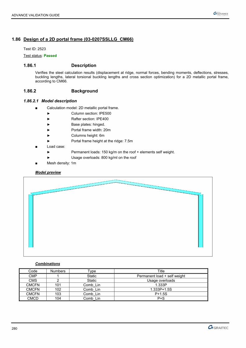
ADVANCE VALIDATION GUIDE
280
1.86 Design of a 2D portal frame (03-0207SSLLG_CM66)
Test ID: 2523
Test status: Passed
1.86.1 Description
Verifies the steel calculation results (displacement at ridge, normal forces, bending moments, deflections, stresses, buckling lengths, lateral torsional buckling lengths and cross section optimization) for a 2D metallic portal frame, according to CM66.
1.86.2 Background
1.86.2.1 Model description
■ Calculation model: 2D metallic portal frame.
► Column section: IPE500
► Rafter section: IPE400
► Base plates: hinged.
► Portal frame width: 20m
► Columns height: 6m
► Portal frame height at the ridge: 7.5m
■ Load case:
► Permanent loads: 150 kg/m on the roof + elements self weight.
► Usage overloads: 800 kg/ml on the roof
■ Mesh density: 1m
Model preview
Combinations
Code Numbers Type Title CMP 1 Static Permanent load + self weight CMS 2 Static Usage overloads
CMCFN 101 Comb_Lin 1.333P CMCFN 102 Comb_Lin 1.333P+1.5S CMCFN 103 Comb_Lin P+1.5S CMCD 104 Comb_Lin P+S

ADVANCE VALIDATION GUIDE
281
1.86.2.2 Effel Structure Results
Ridge displacements (combination 104)
Diagram of normal force envelope

ADVANCE VALIDATION GUIDE
282
Envelope of bending moments diagram
1.86.2.3 Effel Expert CM results
Main hypotheses
For columns
■ Deflections: 1/150
Envelopes deflections calculation.
■ Buckling: XY plane: Automatic calculation of the structure on fixed nodes
XZ plane: Automatic calculation of the structure on fixed nodes
Ka-Kb Method
■ Lateral-torsional buckling: Ldi automatic calculation: no restraints
Lds imposed value: 2 m
For the rafters
■ Deflections: 1/200
Envelopes deflections calculation.
■ Buckling: XY plane: Automatic calculation of the structure on fixed nodes
XZ plane: Automatic calculation of the structure on fixed nodes
Ka-Kb Method
■ Lateral-torsional buckling: Ldi automatic calculation: No restraints
Lds imposed value: 1.5m
Optimization criteria
■ Work ratio optimization between 90 and 100%
■ Labels optimization (on Advance Design templates)
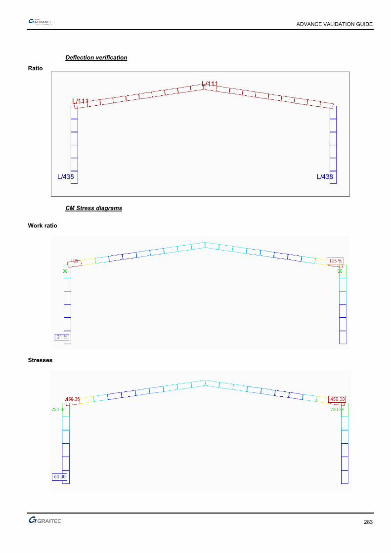
ADVANCE VALIDATION GUIDE
283
Deflection verification
Ratio
CM Stress diagrams
Work ratio
Stresses

ADVANCE VALIDATION GUIDE
284
Buckling lengths
Lfy
Lfz
Lateral-torsional buckling lengths
Ldi

ADVANCE VALIDATION GUIDE
285
Lds
Optimization

ADVANCE VALIDATION GUIDE
286
1.86.2.4 Theoretical results
Solver Result name Result description Reference value
CM2 D Displacement at the ridge [cm] 9.36
CM2 Fx Envelope normal forces on Columns (min) [T] -15.77
CM2 Fx Envelope normal forces on Rafters (max) [T] -1.02
CM2 My Envelope bending moments on Columns (min) [T.m] -42.41
CM2 My Envelope bending moments on Rafters (max) [T.m] 42.41
CM2 Deflection CM deflections on Columns [%] L / 438 (34%)
CM2 Deflection CM deflections on Rafters [%] L / 111 (180%)
CM2 Stress CM stresses on Columns [MPa] 230.34
CM2 Stress CM stresses on Rafters [MPa] 458.38
CM2 Lfy Buckling lengths on Columns - Lfy [m] 5.84
CM2 Lfz Buckling lengths on Columns - Lfz [m] 6
CM2 Lfy Buckling lengths on Rafters - Lfy [m] 7.08
CM2 Lfz Buckling lengths on Rafters - Lfz [m] 10.11
Warning, the local axes in Effel Structure have different orientation in Advance Design.
Solver Result name Result description Reference value
CM2 Ldi Lateral-torsional buckling lengths on Columns Ldi [m] 6
CM2 Lds Lateral-torsional buckling lengths on Columns Lds [m] 2
CM2 Ldi Lateral-torsional buckling lengths on Rafters Ldi [m] 10.11
CM2 Lds Lateral-torsional buckling lengths on Rafters Lds [m] 1.5
Solver Result name Result description Rate (%) Final section
CM2 Work ratio IPE500 columns - section optimization 98 IPE500
CM2 Work ratio IPE400 rafters - section optimization 195 IPE550

ADVANCE VALIDATION GUIDE
287
1.86.3 Calculated results
Result name Result description Value Error
D Displacement at the ridge [cm] 9.36473 cm 0.05%
Fx Envelope normal forces on Columns (min) [T] -15.7798 T -0.06%
Fx Envelope normal forces on Rafters (max) [T] -1.0161 T 0.38%
My Envelope bending moments on Columns (min) [Tm] 42.4226 T*m 0.03%
My Envelope bending moments on Rafters (max) [Tm] 42.4226 T*m 0.03%
Deflection CM deflections on Columns [adm] 438.077 Adim. 0.02%
Deflection CM deflections on Rafters [adm] 111.325 Adim. 0.29%
Stress CM stresses on Columns [adm] 230.331 MPa 0.00%
Stress CM stresses on Rafters [adm] 458.367 MPa 0.00%
Lfy Buckling lengths on Columns - Lfy [m] 6 m 0.00%
Lfz Buckling lengths on Columns - Lfz [m] 5.84401 m 0.07%
Lfy Buckling lengths on Rafters - Lfy [m] 10.1119 m 0.02%
Lfz Buckling lengths on Rafters - Lfz [m] 7.07904 m -0.01%
Ldi Lateral-torsional buckling lengths on Columns Ldi [m] 6 m 0.00%
Lds Lateral-torsional buckling lengths on Columns Lds [m] 2 m 0.00%
Ldi Lateral-torsional buckling lengths on Rafters Ldi [m] 10.1119 m 0.02%
Lds Lateral-torsional buckling lengths on Rafters Lds [m] 1.5 m 0.00%
Work ratio IPE500 columns - section optimization [adm] 0.980131 Adim. 0.01%
Work ratio IPE400 rafters - section optimization [adm] 1.9505 Adim. 0.03%

ADVANCE VALIDATION GUIDE
288
1.87 Beam on 3 supports with T/C (k = 0) (01-0100SSNLB_FEM)
Test ID: 2514
Test status: Passed
1.87.1 Description
Verifies the rotation, the displacement and the moment on a beam consisting of two elements of the same length and identical characteristics with 3 T/C supports (k = 0).
1.87.2 Background
1.87.2.1 Model description
■ Reference: internal GRAITEC test;
■ Analysis type: static non linear;
■ Element type: linear, T/C.
Units
I. S.
Geometry
■ L= 10 m
■ Section: IPE 200, Iz = 0.00001943 m4
Materials properties
■ Longitudinal elastic modulus: E = 2.1 x 10¹¹ N/m2,
■ Poisson's ratio: = 0.3.
Boundary conditions
■ Outer:
► Support at node 1 restrained along x and y (x = 0),
► Support at node 2 restrained along y (x = 10 m),
► T/C stiffness ky = 0,
■ Inner: None.
Loading
■ External: Vertical punctual load P = -100 N at x = 5 m,
■ Internal: None.

ADVANCE VALIDATION GUIDE
289
1.87.2.2 References solutions
ky being null, the non linear model behaves the same way as the structure without support 3.
Displacements
rad 000153.0
Lk2EI3EI32
LkEI6PL
m 00153.0Lk2EI316
PL3v
rad 000153.0Lk2EI3EI16
LkEI3PL
rad 000153.0Lk2EI3EI32
LkEI2PL3
3yzz
3yz
2
3
3yz
3
3
3yzz
3yz
2
2
3yzz
3yz
2
1
Mz Moments
N.m 2502
MM
4
PL)m5x(M
0Lk2EI316
PLk3M
0M
1z2zz
3yz
4y
2z
1z
Finite elements modeling
■ Linear element: S beam, automatic mesh,
■ 3 nodes,
■ 2 linear elements + 1 T/C.
Deformed shape

ADVANCE VALIDATION GUIDE
290
Moment diagrams
1.87.2.3 Theoretical results
Solver Result name Result description Reference value
CM2 RY Rotation Ry in node 1 [rad] 0.000153
CM2 RY Rotation Ry in node 2 [rad] -0.000153
CM2 DZ Displacement V in node 3 [m] 0.00153
CM2 RY Rotation Ry in node 3 [rad] 0.000153
CM2 My Moment M in node 1 [Nm] 0
CM2 My Moment M - middle span 1 [Nm] -250
1.87.3 Calculated results
Result name Result description Value Error
RY Rotation Ry in node 1 [rad] 0.000153175 Rad 0.11%
RY Rotation Ry in node 2 [rad] -0.000153175 Rad -0.11%
DZ Displacement V in node 3 [m] 0.00153175 m 0.11%
RY Rotation Ry in node 3 [rad] -0.000153175 Rad -0.11%
My Moment M in node 1 [Nm] 5.05771e-014 N*m 0.00%
My Moment M - middle span 1 [Nm] -250 N*m 0.00%
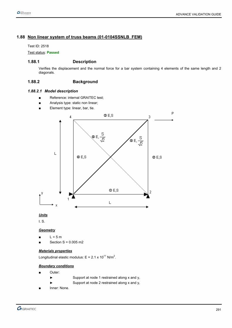
ADVANCE VALIDATION GUIDE
291
1.88 Non linear system of truss beams (01-0104SSNLB_FEM)
Test ID: 2518
Test status: Passed
1.88.1 Description
Verifies the displacement and the normal force for a bar system containing 4 elements of the same length and 2 diagonals.
1.88.2 Background
1.88.2.1 Model description
■ Reference: internal GRAITEC test;
■ Analysis type: static non linear;
■ Element type: linear, bar, tie.
Units
I. S.
Geometry
■ L= 5 m
■ Section S = 0.005 m2
Materials properties
Longitudinal elastic modulus: E = 2.1 x 10¹¹ N/m2.
Boundary conditions
■ Outer:
► Support at node 1 restrained along x and y,
► Support at node 2 restrained along x and y,
■ Inner: None.

ADVANCE VALIDATION GUIDE
292
Loading
■ External: Horizontal punctual load P = 50000 N at node 3,
■ Internal: None.
1.88.2.2 References solutions
In non linear analysis without large displacement, the introduction of ties for the diagonal bars removes bar 5 (test No. 0103SSLLB_FEM allows finding an compression force in this bar at the linear calculation).
Displacements
0v
m 000238.0ES
PLv
m 001195.0ES11
PL5uu
4
3
43
N normal forces
0N 0N
N 70711P2N N 50000PN
0N 0N
4243
1323
1412
Finite elements modeling
■ Linear element: bar, without meshing,
■ 4 nodes,
■ 6 linear elements.
Deformed shape

ADVANCE VALIDATION GUIDE
293
Normal forces

ADVANCE VALIDATION GUIDE
294
1.88.2.3 Theoretical results
Solver Result name Result description Reference value
CM2 DX u3 displacement on Node 3 [m] 0.001195
CM2 DZ v3 displacement on Node 3 [m] -0.000238
CM2 DX u4 displacement on Node 4 [m] 0.001195
CM2 DZ v4 displacement on Node 4 [m] 0
CM2 Fx N12 normal force on Element 1 [N] 0
CM2 Fx N23 normal force on Element 2 [N] -50000
CM2 Fx N34 normal force on Element 3 [N] 0
CM2 Fx N14 normal force on Element 4 [N] 0
CM2 Fx N13 normal effort on Element 5 [N] 70711
CM2 Fx N24 normal force on Element 6 [N] 0
1.88.3 Calculated results
Result name Result description Value Error
DX u3 displacement on Node 3 [m] 0.00119035 m -0.39%
DZ v3 displacement on Node 3 [m] -0.000238095 m -0.04%
DX u4 displacement on Node 4 [m] 0.00119035 m -0.39%
DZ v4 displacement on Node 4 [m] 9.94686e-316 m 0.00%
Fx N12 normal force on Element 1 [N] 0 N 0.00%
Fx N23 normal force on Element 2 [N] -50000 N 0.00%
Fx N34 normal force on Element 3 [N] 0 N 0.00%
Fx N14 normal force on Element 4 [N] 2.08884e-307 N 0.00%
Fx N13 normal effort on Element 5 [N] 70710.7 N 0.00%
Fx N24 normal force on Element 6 [N] 0 N 0.00%
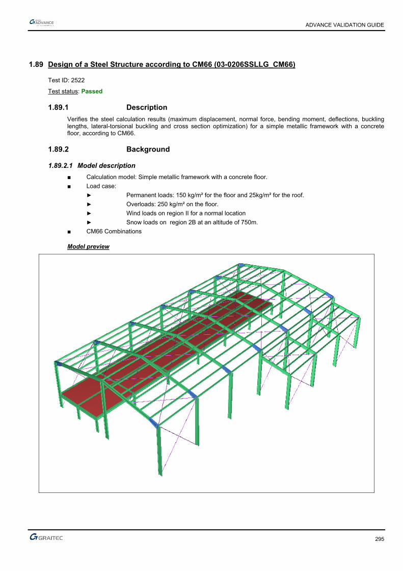
ADVANCE VALIDATION GUIDE
295
1.89 Design of a Steel Structure according to CM66 (03-0206SSLLG_CM66)
Test ID: 2522
Test status: Passed
1.89.1 Description
Verifies the steel calculation results (maximum displacement, normal force, bending moment, deflections, buckling lengths, lateral-torsional buckling and cross section optimization) for a simple metallic framework with a concrete floor, according to CM66.
1.89.2 Background
1.89.2.1 Model description
■ Calculation model: Simple metallic framework with a concrete floor.
■ Load case:
► Permanent loads: 150 kg/m² for the floor and 25kg/m² for the roof.
► Overloads: 250 kg/m² on the floor.
► Wind loads on region II for a normal location
► Snow loads on region 2B at an altitude of 750m.
■ CM66 Combinations
Model preview

ADVANCE VALIDATION GUIDE
296
Structure’s load case
Code No. Type Title CMP 1 Static SW + Dead loads CMS 2 Static Overloads for usage CMV 3 Static Wind overloads along +X in overpressure CMV 4 Static Wind overloads along +X in depression CMV 5 Static Wind overloads along -X in overpressure CMV 6 Static Wind overloads along -X in depression CMV 7 Static Wind overloads along +Z in overpressure CMV 8 Static Wind overloads along +Z in depression CMV 9 Static Wind overloads along -Z in overpressure CMV 10 Static Wind overloads along -Z in depression CMN 11 Static Normal snow overloads
1.89.2.2 Effel Structure results
Displacement Envelope (“CMCD" load combinations)
Envelope of linear element forces D DX DY DZ
Env. Case No. Max.
location (cm) (cm) (cm) (cm) Max(D) 213 148 CENTER 12.115 0.037 12.035 -1.393 Min(D) 188 1.1 START 0.000 0.000 0.000 0.000
Max(DX) 204 72.1 START 3.138 3.099 0.434 0.244 Min(DX) 204 313 END 2.872 -1.872 -0.129 -2.174 Max(DY) 213 148 CENTER 12.115 0.037 12.035 -1.393 Min(DY) 213 61.5 END 9.986 -0.118 -9.985 0.046 Max(DZ) 201 371 CENTER 4.149 -0.006 -0.188 4.145 Min(DZ) 203 370 CENTER 4.124 -0.006 -0.240 -4.118
Envelope of forces on linear elements (“CMCFN” load combinations)
Envelope of linear element forces Fx Fy Fz Mx My Mz
Env. Case No. MaxSite (T) (T) (T) (T*m) (T*m) (T*m)
Max (Fx) 120 4.1 START 19.423 -4.108 -1.384 -0.003 1.505 7.551 Min (Fx) 138 98 START -41.618 -0.962 -0.192 0.000 0.000 0.000 Max(Fy) 120 57 END -13.473 16.349 -0.016 -0.003 0.002 55.744 Min(Fy) 120 60 START -15.994 -16.112 -0.006 -3E-004 6E-006 53.096 Max(Fz) 177 371 START -3.486 -0.118 2.655 0.000 0.000 0.000 Min(Fz) 187 370 START -3.666 -0.147 -2.658 0.000 0.000 0.000 Max(Mx) 120 111 END 3.933 4.840 0.278 0.028 -4E-005 11.531 Min(Mx) 120 21 END -22.324 13.785 -0.191 -0.028 -0.004 42.562 Max(My) 177 371 CENTER -3.099 -0.118 -0.323 0.000 4.403 -0.500 Min(My) 179 370 CENTER -3.283 -0.155 0.321 0.000 -4.373 -0.660 Max (Mz) 120 57 END -13.473 16.349 -0.016 -0.003 0.002 55.744 Min (Mz) 120 59.2 END -19.455 -8.969 -0.702 -0.003 -0.001 -57.105 Envelope of linear element stresses (“CMCFN” load combinations)
Envelope of linear element stresses sxxMax sxyMax sxzMax sFxx sMxxMax
Env. Case No. MaxSite (MPa) (MPa) (MPa) (MPa) (MPa)
Max(sxxMax) 120 59.2 END 273.860 -14.696 -1.024 -16.453 290.312 Min(sxxMax) 120 292 START -150.743 0.000 0.000 -150.743 0.000 Max(sxyMax) 120 57 START 262.954 37.139 -0.030 -15.609 278.562 Min(sxyMax) 120 60 END 241.643 -36.595 -0.011 -18.536 260.179 Max(sxzMax) 185 371 START -2.949 -0.183 3.876 -2.949 0.000 Min(sxzMax) 179 370 START -3.104 -0.255 -3.882 -3.104 0.000 Max(sFxx) 120 293 END 161.095 9E-005 -0.002 161.095 0.000 Min(sFxx) 120 292 START -150.743 0.000 0.000 -150.743 0.000
Max(sMxxMax) 120 59.2 END 273.860 -14.696 -1.024 -16.453 290.312 Min(sMxxMax) 1 1.1 START -4.511 3.155 -0.646 -4.511 0.000

ADVANCE VALIDATION GUIDE
297
1.89.2.3 CM66 Effel Expertise results
Hypotheses
For columns
■ Deflections: 1/150
Envelopes deflections calculation.
■ Buckling XY plane: Automatic calculation of the structure on displaceable nodes
XZ plane: Automatic calculation of the structure on fixed nodes
■ Lateral-torsional buckling: Ldi automatic calculation: hinged restraint
Lds automatic calculation: hinged restraint
For rafters
■ Deflections: 1/200
Envelopes deflections calculation.
■ Buckling: XY plane: Automatic calculation of the structure on displaceable nodes
XZ plane: Automatic calculation of the structure on fixed nodes
■ Lateral-torsional buckling: Ldi automatic calculation: no restraint
Lds automatic calculation: hinged restraint
For columns
■ Deflections: 1/150
Envelopes deflections calculation.
■ Buckling: XY plane: Automatic calculation of the structure on displaceable nodes
XZ plane: Automatic calculation of the structure on displaceable nodes
■ Lateral-torsional buckling: Ldi automatic calculation: hinged restraint
Lds automatic calculation: hinged restraint
Optimization parameters
■ Work ratio optimization between 90 and 100%
■ All the sections from the library are available.
■ Labels optimization.
The results of the optimization given below correspond to an iteration of the finite elements calculation.

ADVANCE VALIDATION GUIDE
298
Deflection verification
Ratio
Max values on the element
■ Columns: L / 168
■ Rafter: L / 96
■ Column: L / 924
CM Stress diagrams

ADVANCE VALIDATION GUIDE
299
Work ratio
Stresses
Max values on the element
■ Columns: 375.16 MPa
■ Rafter: 339.79 MPa
■ Column: 180.98 MPa
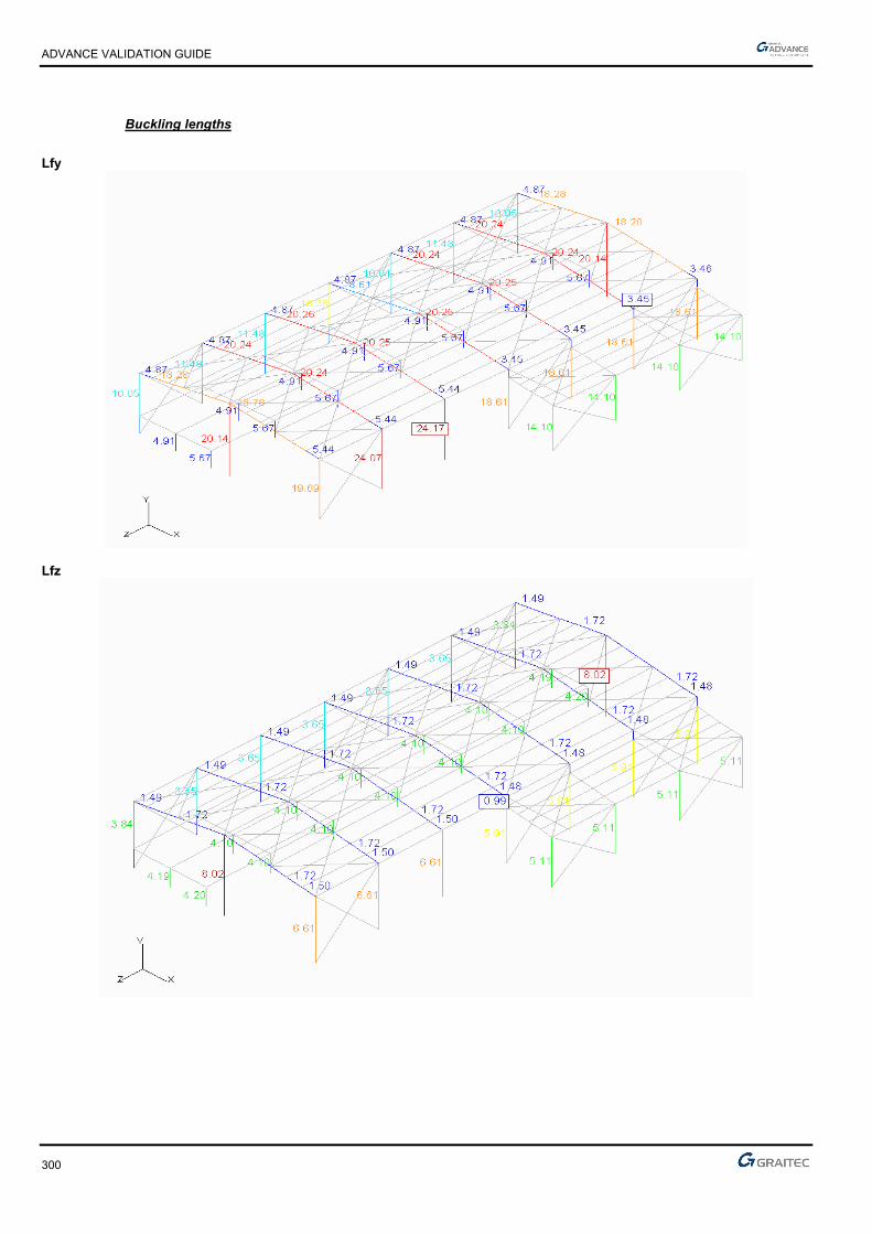
ADVANCE VALIDATION GUIDE
300
Buckling lengths
Lfy
Lfz

ADVANCE VALIDATION GUIDE
301
Lateral-torsional buckling lengths
Ldi
Lds

ADVANCE VALIDATION GUIDE
302
Optimization
1.89.2.4 Theoretical results
Solver Result name Result description Reference value
CM2 D Maximum displacement (CMCD) [cm] 12.115
CM2 Fx Envelope normal force (CMCFN) Min (Fx) [T] -41.618
CM2 Fx Envelope normal force (CMCFN) Max (Fx) [T] 19.423
CM2 My Envelope bending moment (CMCFN) Min (Mz) [Tm] -57.105
CM2 My Envelope bending moment (CMCFN) Max (Mz) [Tm] 55.744
Warning, the Mz bending moment of Effel Structure corresponds to the My bending moment of Advance Design.
Solver Result name Result description Reference value
CM2 Deflection CM deflections on Columns [adm] L / 168 (89%)
CM2 Deflection CM deflections on Rafters [adm] L / 96 (208%)
CM2 Deflection CM deflections on Columns [adm] L / 924 (16%)
CM2 Stress CM stresses on Columns [MPa] 374.67
CM2 Stress CM stresses on Rafters [MPa] 339.74
CM2 Stress CM stresses on Columns [MPa] 180.98
CM2 Lfy Buckling lengths on Columns Lfy [m] 8.02
CM2 Lfz Buckling lengths on Columns Lfz [m] 24.07
CM2 Lfy Buckling lengths on Rafters Lfy [m] 1.72
CM2 Lfz Buckling lengths on Rafters Lfz [m] 20.25
CM2C Lfy Buckling lengths on Columns Lfy [m] 4.20
CM2 Lfz Buckling lengths on Columns Lfz [m] 5.67
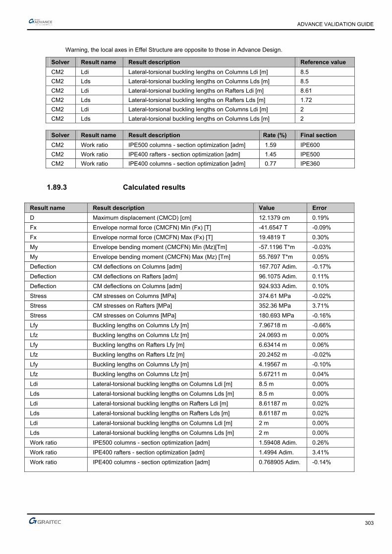
ADVANCE VALIDATION GUIDE
303
Warning, the local axes in Effel Structure are opposite to those in Advance Design.
Solver Result name Result description Reference value
CM2 Ldi Lateral-torsional buckling lengths on Columns Ldi [m] 8.5
CM2 Lds Lateral-torsional buckling lengths on Columns Lds [m] 8.5
CM2 Ldi Lateral-torsional buckling lengths on Rafters Ldi [m] 8.61
CM2 Lds Lateral-torsional buckling lengths on Rafters Lds [m] 1.72
CM2 Ldi Lateral-torsional buckling lengths on Columns Ldi [m] 2
CM2 Lds Lateral-torsional buckling lengths on Columns Lds [m] 2
Solver Result name Result description Rate (%) Final section
CM2 Work ratio IPE500 columns - section optimization [adm] 1.59 IPE600
CM2 Work ratio IPE400 rafters - section optimization [adm] 1.45 IPE500
CM2 Work ratio IPE400 columns - section optimization [adm] 0.77 IPE360
1.89.3 Calculated results
Result name Result description Value Error
D Maximum displacement (CMCD) [cm] 12.1379 cm 0.19%
Fx Envelope normal force (CMCFN) Min (Fx) [T] -41.6547 T -0.09%
Fx Envelope normal force (CMCFN) Max (Fx) [T] 19.4819 T 0.30%
My Envelope bending moment (CMCFN) Min (Mz)[Tm] -57.1196 T*m -0.03%
My Envelope bending moment (CMCFN) Max (Mz) [Tm] 55.7697 T*m 0.05%
Deflection CM deflections on Columns [adm] 167.707 Adim. -0.17%
Deflection CM deflections on Rafters [adm] 96.1075 Adim. 0.11%
Deflection CM deflections on Columns [adm] 924.933 Adim. 0.10%
Stress CM stresses on Columns [MPa] 374.61 MPa -0.02%
Stress CM stresses on Rafters [MPa] 352.36 MPa 3.71%
Stress CM stresses on Columns [MPa] 180.693 MPa -0.16%
Lfy Buckling lengths on Columns Lfy [m] 7.96718 m -0.66%
Lfz Buckling lengths on Columns Lfz [m] 24.0693 m 0.00%
Lfy Buckling lengths on Rafters Lfy [m] 6.63414 m 0.06%
Lfz Buckling lengths on Rafters Lfz [m] 20.2452 m -0.02%
Lfy Buckling lengths on Columns Lfy [m] 4.19567 m -0.10%
Lfz Buckling lengths on Columns Lfz [m] 5.67211 m 0.04%
Ldi Lateral-torsional buckling lengths on Columns Ldi [m] 8.5 m 0.00%
Lds Lateral-torsional buckling lengths on Columns Lds [m] 8.5 m 0.00%
Ldi Lateral-torsional buckling lengths on Rafters Ldi [m] 8.61187 m 0.02%
Lds Lateral-torsional buckling lengths on Rafters Lds [m] 8.61187 m 0.02%
Ldi Lateral-torsional buckling lengths on Columns Ldi [m] 2 m 0.00%
Lds Lateral-torsional buckling lengths on Columns Lds [m] 2 m 0.00%
Work ratio IPE500 columns - section optimization [adm] 1.59408 Adim. 0.26%
Work ratio IPE400 rafters - section optimization [adm] 1.4994 Adim. 3.41%
Work ratio IPE400 columns - section optimization [adm] 0.768905 Adim. -0.14%

ADVANCE VALIDATION GUIDE
304
1.90 Slender beam with variable section (fixed-free) (01-0004SDLLB_FEM)
Test ID: 2436
Test status: Passed
1.90.1 Description
Verifies the first eigen mode frequencies for a slender beam with variable section, subjected to its own weight.
1.90.2 Background
1.90.2.1 Model description
■ Reference: Structure Calculation Software Validation Guide, test SDLL 09/89;
■ Analysis type: modal analysis;
■ Element type: linear.
Slender beam with variable section (fixed-free) Scale =1/4
01-0004SDLLB_FEM
Units
I. S.
Geometry
■ Beam length: l = 1 m,
■ Initial section (in A):
► Height: h1 = 0.04 m,
► Width: b1 = 0.04 m,
► Section: A1 = 1.6 x 10⁻³ m2,
► Flexure moment of inertia relative to z-axis: Iz1 = 2.1333 x 10⁻⁷ m4,

ADVANCE VALIDATION GUIDE
305
■ Final section (in B):
► Height: h2 = 0.01 m,
► Width: b2 = 0.01 m,
► Section: A2 = 10-4 m2,
► Flexure moment of inertia relative to z-axis: Iz2 = 8.3333 x 10⁻¹⁰ m4.
Materials properties
■ Longitudinal elastic modulus: E = 2 x 10¹¹ Pa,
■ Density: 7800 kg/m3.
Boundary conditions
■ Outer: Fixed in A,
■ Inner: None.
Loading
■ External: None,
■ Internal: None.
1.90.2.2 Eigen mode frequencies
Reference solutions
Precise calculation by numerical integration of the differential equation of beams bending (Euler-Bernoulli theories):
2
x2 (EIz 2vx2 ) = -A
2vx2 where Iz and A vary with the abscissa.
The result is: fi = 12 i
h2
l2 E
12
1 2 3 4 5
23.289 73.9 165.23 299.7 478.1
Finite elements modeling
■ Linear element: variable beam, imposed mesh,
■ 31 nodes,
■ 30 linear elements.
Eigen mode shapes
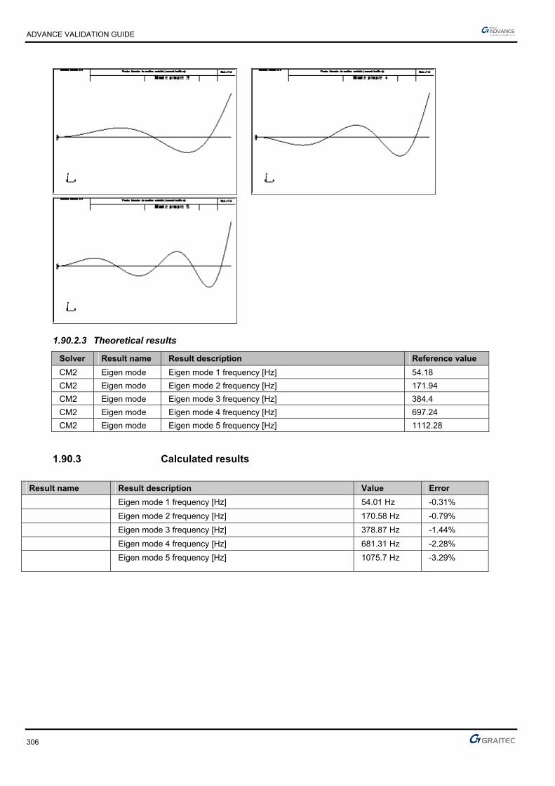
ADVANCE VALIDATION GUIDE
306
1.90.2.3 Theoretical results
Solver Result name Result description Reference value
CM2 Eigen mode Eigen mode 1 frequency [Hz] 54.18
CM2 Eigen mode Eigen mode 2 frequency [Hz] 171.94
CM2 Eigen mode Eigen mode 3 frequency [Hz] 384.4
CM2 Eigen mode Eigen mode 4 frequency [Hz] 697.24
CM2 Eigen mode Eigen mode 5 frequency [Hz] 1112.28
1.90.3 Calculated results
Result name Result description Value Error
Eigen mode 1 frequency [Hz] 54.01 Hz -0.31%
Eigen mode 2 frequency [Hz] 170.58 Hz -0.79%
Eigen mode 3 frequency [Hz] 378.87 Hz -1.44%
Eigen mode 4 frequency [Hz] 681.31 Hz -2.28%
Eigen mode 5 frequency [Hz] 1075.7 Hz -3.29%
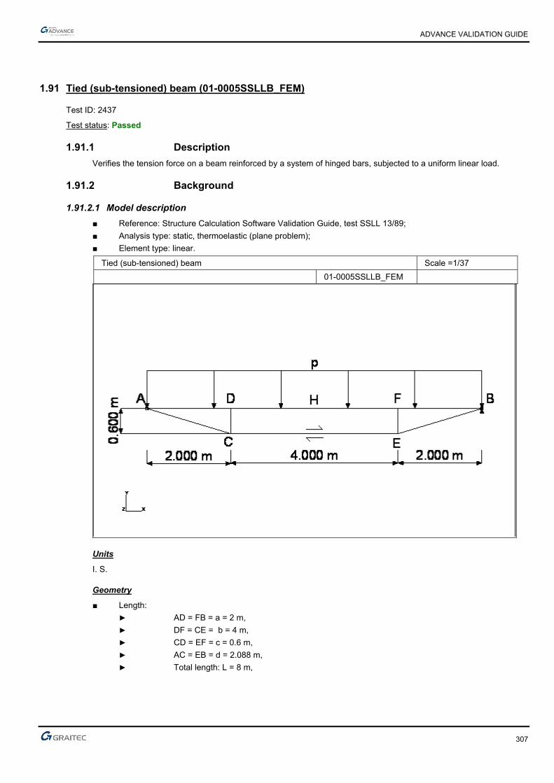
ADVANCE VALIDATION GUIDE
307
1.91 Tied (sub-tensioned) beam (01-0005SSLLB_FEM)
Test ID: 2437
Test status: Passed
1.91.1 Description
Verifies the tension force on a beam reinforced by a system of hinged bars, subjected to a uniform linear load.
1.91.2 Background
1.91.2.1 Model description
■ Reference: Structure Calculation Software Validation Guide, test SSLL 13/89;
■ Analysis type: static, thermoelastic (plane problem);
■ Element type: linear.
Tied (sub-tensioned) beam Scale =1/37
01-0005SSLLB_FEM
Units
I. S.
Geometry
■ Length:
► AD = FB = a = 2 m,
► DF = CE = b = 4 m,
► CD = EF = c = 0.6 m,
► AC = EB = d = 2.088 m,
► Total length: L = 8 m,

ADVANCE VALIDATION GUIDE
308
■ AD, DF, FB Beams:
► Section: A = 0.01516 m2,
► Shear area: Ar = A / 2.5,
► Inertia moment: I = 2.174 x 10⁻⁴ m4,
■ CE Bar:
► Section: A1 = 4.5 x 10⁻³ m2,
■ AC, EB bar:
► Section: A2 = 4.5 x 10⁻³ m2,
■ CD, EF bars:
► Section: A3 = 3.48 x 10⁻³ m2.
Materials properties
■ Isotropic linear elastic material,
■ Longitudinal elastic modulus: E = 2.1 x 10¹¹ Pa,
■ Shearing module: G = 0.4x E.
Boundary conditions
■ Outer: Hinged in A, support connection in B (blocked vertical translation),
■ Inner: Hinged at bar ends: AC, CD, EF, EB.
Loading
■ External: Uniform linear load p = -50000 N/ml,
■ Internal: Shortening of the CE tie of = 6.52 x 10⁻³ m (dilatation coefficient: CE = 1 x 10⁻⁵ /°C and temperature variation T = -163°C).
1.91.2.2 Compression force in CE bar
Reference solution
The solution is established by considering the deformation effects due to the shear force and normal force:
= 1 - 43 x
aL
k = AAr
= 2.5
t = IA
= (L/c)2 x (1+ (A/A1) x (b/L) + 2 x (A/A2) x (d/a)2 x (d/L) + 2 x (A/A3) (c/a)2 x (c/L)
= k x [(2Et2) / (GaL)]
= + +
0 = 1 – (a/L)2 x (2 – a/L)
0 = 6k x (E/G) x (t/L)2 x (1 + b/L)
0 = 0 + 0
NCE = - (1/12) x (pL2/c) x (0 /) + (EI/(Lc2)) x (/) = 584584 N
Finite elements modeling
Linear element: without meshing,
■ AD, DF, FB: S beam (considering the shear force deformations),
■ AC, CD, EF, EB: bar,
■ CE: beam,
■ 6 nodes.

ADVANCE VALIDATION GUIDE
309
Force diagrams
Tied (sub-tensioned) beam Scale =1/31
Compression force in CE bar
1.91.2.3 Bending moment at point H
Reference solution
MH = - (1/8) x pL2 x [1- (2/3) x (0/)] – (EI/(Lc)) x (/p) = 49249.5 N
Finite elements modeling
Linear element: without meshing,
■ AD, DF, FB: S beam (considering the shear force deformations),
■ AC, CD, EF, EB: bar,
■ CE: beam,
■ 6 nodes.
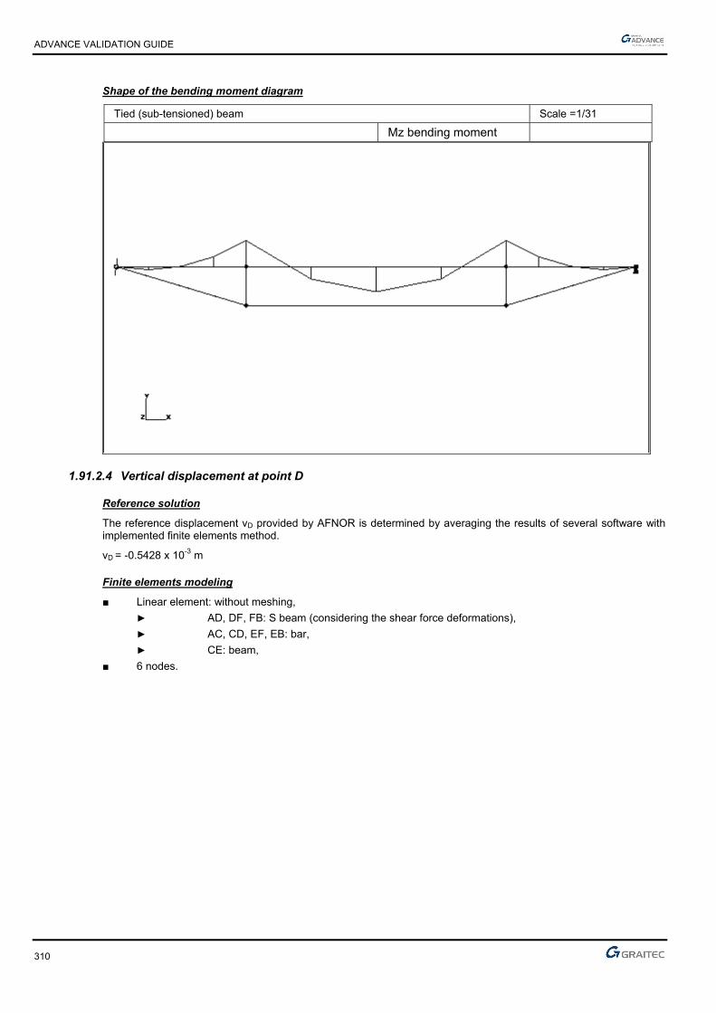
ADVANCE VALIDATION GUIDE
310
Shape of the bending moment diagram
Tied (sub-tensioned) beam Scale =1/31
Mz bending moment
1.91.2.4 Vertical displacement at point D
Reference solution
The reference displacement vD provided by AFNOR is determined by averaging the results of several software with implemented finite elements method.
vD = -0.5428 x 10⁻³ m
Finite elements modeling
■ Linear element: without meshing,
► AD, DF, FB: S beam (considering the shear force deformations),
► AC, CD, EF, EB: bar,
► CE: beam,
■ 6 nodes.
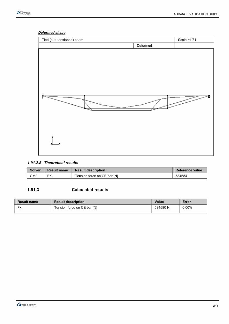
ADVANCE VALIDATION GUIDE
311
Deformed shape
Tied (sub-tensioned) beam Scale =1/31
Deformed
1.91.2.5 Theoretical results
Solver Result name Result description Reference value
CM2 FX Tension force on CE bar [N] 584584
1.91.3 Calculated results
Result name Result description Value Error
Fx Tension force on CE bar [N] 584580 N 0.00%
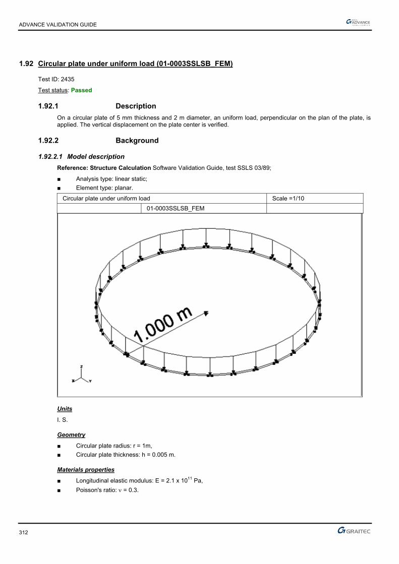
ADVANCE VALIDATION GUIDE
312
1.92 Circular plate under uniform load (01-0003SSLSB_FEM)
Test ID: 2435
Test status: Passed
1.92.1 Description
On a circular plate of 5 mm thickness and 2 m diameter, an uniform load, perpendicular on the plan of the plate, is applied. The vertical displacement on the plate center is verified.
1.92.2 Background
1.92.2.1 Model description
Reference: Structure Calculation Software Validation Guide, test SSLS 03/89;
■ Analysis type: linear static;
■ Element type: planar.
Circular plate under uniform load Scale =1/10
01-0003SSLSB_FEM
Units
I. S.
Geometry
■ Circular plate radius: r = 1m,
■ Circular plate thickness: h = 0.005 m.
Materials properties
■ Longitudinal elastic modulus: E = 2.1 x 10¹¹ Pa,
■ Poisson's ratio: = 0.3.

ADVANCE VALIDATION GUIDE
313
Boundary conditions
■ Outer: Plate fixed on the side (in all points of its perimeter),
For the modeling, we consider only a quarter of the plate and we impose symmetry conditions on some nodes (see the following model; yz plane symmetry condition):translation restrained nodes along x and rotation restrained nodes along y and z: translation restrained nodes along x and rotation restrained nodes along y and z:
■ Inner: None.
Loading
■ External: Uniform loads perpendicular on the plate: pZ = -1000 Pa,
■ Internal: None.
1.92.2.2 Vertical displacement of the model at the center of the plate
Reference solution
Circular plates form:
u = pr4
64D = -1000 x 14
64 x 2404 = - 6.50 x 10⁻³ m
with the plate radius coefficient: D = Eh3
12(1-2) =
2.1 x 1011 x 0.0053
12(1-0.32)
D = 2404
Finite elements modeling
■ Planar element: plate, imposed mesh,
■ 70 nodes,
■ 58 planar elements.
Circular plate under uniform load Scale =1.5
Meshing 01-0003SSLSB_FEM

ADVANCE VALIDATION GUIDE
314
Deformed shape
Circular plate under uniform load Scale =1.5
Deformed 01-0003SSLSB_FEM
1.92.2.3 Theoretical results
Solver Result name Result description Reference value
CM2 DZ Vertical displacement on the plate center [mm] -6.50
1.92.3 Calculated results
Result name Result description Value Error
DZ Vertical displacement on the plate center [mm] -6.47032 mm 0.46%
ADVANCE VALIDATION GUIDE
315
1.93 Verifying the displacement results on linear elements for vertical seism (TTAD #11756)
Test ID: 3442
Test status: Passed
1.93.1 Description
Verifies the displacements results on an inclined steel bar for vertical seism according to Eurocodes 8 localization and generates the corresponding report.
The steel bar has a rigid support and IPE100 cross section and is subjected to self weight and seism load on Z direction (vertical).
1.94 Verifying constraints for triangular mesh on planar elements (TTAD #11447)
Test ID: 3460
Test status: Passed
1.94.1 Description
Performs the finite elements calculation, verifies the stresses for triangular mesh on a planar element and generates a report for planar elements stresses in neutral fiber.
The planar element is 20 cm thick, C20/25 material with a linear rigid support. A linear load of 30.00 kN is applied on FX direction.
1.95 Verifying forces results on concrete linear elements (TTAD #11647)
Test ID: 3551
Test status: Passed
1.95.1 Description
Verifies forces results on concrete beams consisting of a linear element and on beams consisting of two linear elements. Generates the linear elements forces by load case report.
1.96 Verifying diagrams after changing the view from standard (top, left,...) to user view (TTAD #11854)
Test ID: 3539
Test status: Passed
1.96.1 Description
Verifies the results diagrams display after changing the view from standard (top, left,...) to user view.
1.97 Verifying forces for triangular meshing on planar element (TTAD #11723)
Test ID: 3463
Test status: Passed
1.97.1 Description
Performs the finite elements calculation, verifies the forces for triangular meshing on a planar element and generates a report for planar elements forces by load case.
The planar element is a square shell (5 m) with a thickness of 20 cm, C20/25 material with a linear rigid support. A linear load of -10.00 kN is applied on FZ direction.
ADVANCE VALIDATION GUIDE
316
ADVANCE VALIDATION GUIDE
317
1.98 Verifying stresses in beam with "extend into wall" property (TTAD #11680)
Test ID: 3491
Test status: Passed
1.98.1 Description
Verifies the results on two concrete beams which have the "Extend into the wall" option enabled. One of the beams is connected to 2 walls on both sides and one with a wall and a pole. Generates the linear elements forces by elements report.
1.99 Generating planar efforts before and after selecting a saved view (TTAD #11849)
Test ID: 3454
Test status: Passed
1.99.1 Description
Generates efforts for all planar elements before and after selecting the third saved view.
1.100 Verifying results on punctual supports (TTAD #11489)
Test ID: 3693
Test status: Passed
1.100.1 Description
Performs the finite elements calculation and generates the punctual supports report, containing the following tables: "Displacements of point supports by load case", "Displacements of point supports by element", "Point support actions by load case", "Point support actions by element" and "Sum of actions on supports and nodes restraints".
The structure consists of concrete, steel and timber linear elements with punctual supports.
1.101 Verifying the level mass center (TTAD #11573, TTAD #12315)
Test ID: 3609
Test status: Passed
1.101.1 Description
Performs the finite elements calculation on a model with two planar concrete elements with a linear support. Verifies the level mass center and generates the "Excited total masses" and "Level modal mass and rigidity centers" reports.
The model consists of two planar concrete elements with a linear fixed support. The loads applied on the model: self weight, a planar live load of -1 kN and seism loads according to French standards of Eurocodes 8.
1.102 Verifying diagrams for Mf Torsors on divided walls (TTAD #11557)
Test ID: 3610
Test status: Passed
1.102.1 Description
Performs the finite elements calculation and verifies the results diagrams for Mf torsors on a high wall divided in 6 walls (by height).
The loads applied on the model: self weight, two live load cases and seism loads according to Eurocodes 8.
ADVANCE VALIDATION GUIDE
318
1.103 Verifying Sxx results on beams (TTAD #11599)
Test ID: 3595
Test status: Passed
1.103.1 Description
Performs the finite elements calculation on a complex model with concrete, steel and timber elements. Verifies the Sxx results on beams. Generates the maximum stresses report.
The structure has 40 timber linear elements, 24 concrete linear elements, 143 steel elements. The loads applied on the structure: dead loads, live loads, snow loads, wind loads and temperature loads (according to Eurocodes).
1.104 Generating results for Torsors NZ/Group (TTAD #11633)
Test ID: 3594
Test status: Passed
1.104.1 Description
Performs the finite elements calculation on a complex concrete structure with four levels. Generates results for Torsors NZ/Group. Verifies the legend results.
The structure has 88 linear elements, 30 planar elements, 48 windwalls, etc.
1.105 Verifying nonlinear analysis results for frames with semi-rigid joints and rigid joints (TTAD #11495)
Test ID: 3795
Test status: Passed
1.105.1 Description
Verifies the nonlinear analysis results for two frames with one level. One of the frames has semi-rigid joints and the other has rigid joints.
1.106 Generating a report with torsors per level (TTAD #11421)
Test ID: 3774
Test status: Passed
1.106.1 Description
Generates a report with the torsors per level results.
1.107 Verifying tension/compression supports on nonlinear analysis (TTAD #11518)
Test ID: 4198
Test status: Passed
1.107.1 Description
Verifies the behavior of supports with several rigidities fields defined.
Performs the finite elements calculation and generates the "Displacements of linear elements by element" report.
The model consists of a vertical linear element (concrete B20, R20*30 cross section) with a rigid punctual support at the base and a T/C punctual support at the top. A value of 15000.00 kN/m is defined for the KTX and KTZ stiffeners of the T/C support. Two loads of 500.00 kN are applied.

ADVANCE VALIDATION GUIDE
319
1.108 Verifying tension/compression supports on nonlinear analysis (TTAD #11518)
Test ID: 4197
Test status: Passed
1.108.1 Description
Verifies the supports behavior when the rigidity has a high value.
Performs the finite elements calculation and generates the "Displacements of linear elements by element" report.
The model consists of a vertical linear element (concrete B20, R20*30 cross section) with a rigid punctual support at the base and a T/C punctual support at the top. A large value of the KTX stiffener of the T/C support is defined. Two loads of 500.00 kN are applied.
1.109 Verifying the display of the forces results on planar supports (TTAD #11728)
Test ID: 4375
Test status: Passed
1.109.1 Description
Performs the finite elements calculation and verifies the display of the forces results on a planar support. The model consists of a concrete vertical element with a planar support.

ADVANCE VALIDATION GUIDE
320
1.110 Verifying results of a steel beam subjected to dynamic temporal loadings (TTAD #14586)
Test ID: 5853
Test status: Passed
1.110.1 Description
Verifies a double-end fixed steel beam subjected to harmonic concentrated loadings.
2 Hz and 3 Hz excitation frequencies are studied.
1.110.2 Background
The harmonic response of a steel beam fixed at both ends is studied. The beam contains 8 elements having the same length and identical characteristics. Harmonic concentrated loadings (a vertical load and a bending moment) are applied in the middle of the beam. Two excitation frequencies are studied: 2.0 and 3.0 Hz.
1.110.2.1 Model description
■ Reference: NE/Nastran V8;
■ Analysis type: modal analysis;
■ Element type: linear.
Units
I. S.
Geometry
Below are described the beam cross section characteristics:
■ Beam length: L = 16 m,
■ Square shaped cross section: b = 0.05 m,
■ Section area: A = 0.06 m2,
■ Flexion inertia moment about the y (or z) axis: I = 0.0001 m4.
Materials properties
■ Longitudinal elastic modulus: E = 2.1 x 10¹¹ N/m2,
■ Poisson coefficient: = 0.3,
■ Density: = 7850 kg/m3.
Boundary conditions
■ Outer:
► Fixed support at start point (x = 0),
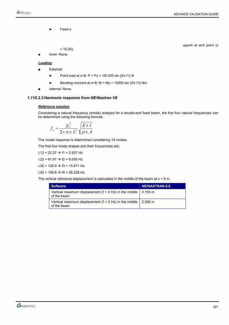
ADVANCE VALIDATION GUIDE
321
► Fixed s upport at end point (x = 16.00).
■ Inner: None.
Loading
■ External:
► Point load at x=8: P = Fz = -50 000 sin (2π f t) N
► Bending moment at x=8: M = My = 10000 sin (2π f t) Nm
■ Internal: None.
1.110.2.2 Harmonic response from NE/Nastran V8
Reference solution
Considering a natural frequency (modal) analysis for a double-end fixed beam, the first four natural frequencies can be determined using the following formula:
A
IE
Lf nn
2
2
2
The modal response is determined considering 14 modes.
The first four mode shapes and their frequencies are:
12 = 22.37 f1 = 2.937 Hz
22 = 61.67 f2 = 8.095 Hz
32 = 120.9 f3 = 15.871 Hz
42 = 199.8 f4 = 26.228 Hz
The vertical reference displacement is calculated in the middle of the beam at x = 8 m.
Software NE/NASTRAN 8.0
Vertical maximum displacement (f = 2 Hz) in the middle of the beam
0.155 m
Vertical maximum displacement (f = 3 Hz) in the middle of the beam
2.266 m

ADVANCE VALIDATION GUIDE
322
Response in the middle of the beam with f = 2 Hz
Response in the middle of the beam with f = 3 Hz
Finite elements modeling
■ Linear element: beam, imposed mesh
■ 9 nodes,
■ 8 linear elements.
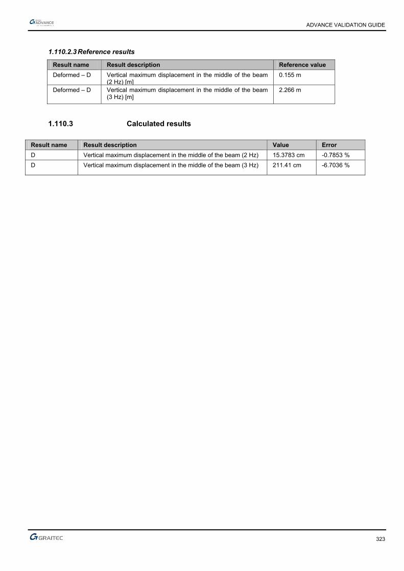
ADVANCE VALIDATION GUIDE
323
1.110.2.3 Reference results
Result name Result description Reference value
Deformed – D Vertical maximum displacement in the middle of the beam (2 Hz) [m]
0.155 m
Deformed – D Vertical maximum displacement in the middle of the beam (3 Hz) [m]
2.266 m
1.110.3 Calculated results
Result name Result description Value Error
D Vertical maximum displacement in the middle of the beam (2 Hz) 15.3783 cm -0.7853 %
D Vertical maximum displacement in the middle of the beam (3 Hz) 211.41 cm -6.7036 %
1.111 Verifying the main axes results on a planar element (TTAD #11725)
Test ID: 4310
Test status: Passed
1.111.1 Description
Verifies the main axes results on a planar element.
Performs the finite elements calculation for a concrete wall (20 cm thick) with a linear support. Displays the forces results on the planar element main axes.
1.112 Verifying torsors on a single story coupled walls subjected to horizontal forces
Test ID: 4804
Test status: Passed
1.112.1 Description
Verifies torsors on a single story coupled walls subjected to horizontal forces
1.113 Calculating torsors using different mesh sizes for a concrete wall subjected to a horizontal force (TTAD #13175)
Test ID: 5088
Test status: Passed
1.113.1 Description
Calculates torsors using different mesh sizes for a concrete wall subjected to a horizontal force.
1.114 Verifying the internal forces results for a simple supported steel beam
Test ID: 4533
Test status: Passed
1.114.1 Description
Performs the finite elements calculation for a horizontal element (S235 material and IPE180 cross section) with two hinge rigid supports at each end. One of the supports has translation restraints on X, Y and Z, the other support has restraints on Y and Z.
Verifies the internal forces My, Fz.
Validated according to:
Example: 3.1 - Simple beam bending without the stability loss
Publication: Steel structures members - Examples according to Eurocodes
By: F. Wald a kol.

325
1.115 Verifying forces on a linear elastic support which is defined in a user workplane (TTAD #11929)
Test ID: 4553
Test status: Passed
1.115.1 Description
Verifies forces on a linear elastic support, which is defined in a user workplane, and generates a report with forces for linear support in global and local workplane.


2 CAD, rendering and visualization
ADVANCE VALIDATION GUIDE
328
2.1 Verifying hide/show elements command (TTAD #11753)
Test ID: 3443
Test status: Passed
2.1.1 Description
Verifies the hide/show elements command for the whole structure using the right-click option.
2.2 Verifying the dimensions and position of annotations on selection when new analysis is made.(TTAD #12807)
Test ID: 6201
Test status: Passed
2.2.1 Description
Verifies the dimensions and position of annotations on selection when new analysis is made. It takes a printscreen of the loaded saved view.
2.3 Verifying the saved view of elements with annotations. (TTAD #13033)
Test ID: 6209
Test status: Passed
2.3.1 Description
Verifies the saved view of elements with annotations. It makes saved views and takes printscreens of them after switching between them.
2.4 Verifying the visualisation of supports with rotational or moving DoFs.(TTAD #13891)
Test ID: 6213
Test status: Passed
2.4.1 Description
Verifies the visualisation of supports with rotational or moving DoFs by taking a printscreen.
2.5 Verifying the annotations of a wind generated load. (TTAD #13190)
Test ID: 6210
Test status: Passed
2.5.1 Description
Verifies annotations of a wind generated load. It generates wind on the current 2 slope building( the remarks are filled) then hides all the elements, makes visible only the load with identifier 1 and takes a printscreen.

ADVANCE VALIDATION GUIDE
329
2.6 System stability during section cut results verification (TTAD #11752)
Test ID: 3457
Test status: Passed
2.6.1 Description
Performs the finite elements calculation and verifies the section cut results on a concrete planar element with an opening.
2.7 Generating combinations (TTAD #11721)
Test ID: 3468
Test status: Passed
2.7.1 Description
Generates combinations for three types of loads: live loads, dead loads and snow (with an altitude > 1000 m and base effect); generates the combinations description report.
2.8 Verifying the grid text position (TTAD #11704)
Test ID: 3464
Test status: Passed
2.8.1 Description
Verifies the grid text position from different views.
2.9 Verifying descriptive actors after creating analysis (TTAD #11589)
Test ID: 3579
Test status: Passed
2.9.1 Description
Generates the finite elements calculation on a complex concrete structure (C35/45 material). Verifies the descriptive actors after creating the analysis.
The structure consists of 42 linear elements, 303 planar elements, 202 supports, etc. 370 planar loads are applied: live loads, dead loads and temperature.
2.10 Verifying the coordinates system symbol (TTAD #11611)
Test ID: 3550
Test status: Passed
2.10.1 Description
Verifies the coordinates system symbol display from different views.

ADVANCE VALIDATION GUIDE
330
2.11 Creating a circle (TTAD #11525)
Test ID: 3607
Test status: Passed
2.11.1 Description
Creates a circle.
2.12 Creating a camera (TTAD #11526)
Test ID: 3608
Test status: Passed
2.12.1 Description
Verifies the camera creation and visibility.
2.13 Verifying the representation of elements with HEA cross section (TTAD #11328)
Test ID: 3701
Test status: Passed
2.13.1 Description
Verifies the representation of elements with HEA340 cross section.
2.14 Verifying the snap points behavior during modeling (TTAD #11458)
Test ID: 3644
Test status: Passed
2.14.1 Description
Verifies the snap points behavior when the "Allowed deformation" function is enabled (stretch points) and when it is disabled (grip points).
2.15 Verifying the local axes of a section cut (TTAD #11681)
Test ID: 3637
Test status: Passed
2.15.1 Description
Changes the local axes of a section cut in the descriptive model and verifies if the local axes are kept in analysis model.

ADVANCE VALIDATION GUIDE
331
2.16 Verifying the descriptive model display after post processing results in analysis mode (TTAD #11475)
Test ID: 3733
Test status: Passed
2.16.1 Description
Performs the finite elements calculation and displays the forces results on linear elements. Returns to the model mode to verify the descriptive model display.
2.17 Modeling using the tracking snap mode (TTAD #10979)
Test ID: 3745
Test status: Passed
2.17.1 Description
Enables the "tracking" snap mode to model structure elements.
2.18 Verifying holes in horizontal planar elements after changing the level height (TTAD #11490)
Test ID: 3740
Test status: Passed
2.18.1 Description
Verifies holes in horizontal planar elements after changing the level height.
2.19 Verifying the display of elements with compound cross sections (TTAD #11486)
Test ID: 3742
Test status: Passed
2.19.1 Description
Creates an element with compound cross section (CS1 IPE400 IPE240) and verifies the cross section display.
2.20 Moving a linear element along with the support (TTAD #12110)
Test ID: 4302
Test status: Passed
2.20.1 Description
Moves a linear element along with the element support, after selecting both elements.
ADVANCE VALIDATION GUIDE
332
2.21 Turning on/off the "ghost" rendering mode (TTAD #11999)
Test ID: 4304
Test status: Passed
2.21.1 Description
Verifies the on/off function for the "ghost" rendering mode when the workplane display is disabled.
2.22 Verifying the "ghost" display after changing the display colors (TTAD #12064)
Test ID: 4349
Test status: Passed
2.22.1 Description
Verifies the "ghost" display on selected elements after changing the element display color.
2.23 Verifying the grid text position (TTAD #11657)
Test ID: 3465
Test status: Passed
2.23.1 Description
Verifies the grid text position from different views.
2.24 Verifying the "ghost display on selection" function for saved views (TTAD #12054)
Test ID: 4347
Test status: Passed
2.24.1 Description
Verifies the display of saved views which contain elements with the "ghost on selection" function enabled.
2.25 Verifying the steel connections modeling (TTAD #11698)
Test ID: 4440
Test status: Passed
2.25.1 Description
Verifies the modeling of steel connections.
2.26 Verifying the fixed load scale function (TTAD #12183).
Test ID: 4429
Test status: Passed
2.26.1 Description
Verifies the "fixed load scale" function.

ADVANCE VALIDATION GUIDE
333
2.27 Verifying the saved view of elements by cross-section. (TTAD #13197)
Test ID: 6180
Test status: Passed
2.27.1 Description
Verifies the saved view of elements by cross-section. It takes a printscreen of the loaded saved view.
2.28 Verifying the annotations dimensions when new analysis is made.(TTAD #14825)
Test ID: 6199
Test status: Passed
2.28.1 Description
Verifies the annotations dimensions when new analysis is made. It takes a printscreen of the loaded saved view.
2.29 Verifying the default view.(TTAD #13248)
Test ID: 6198
Test status: Passed
2.29.1 Description
Verifies the default view to be the top view. It takes a printscreen of the loaded saved view.
2.30 Verifying the dividing of planar elements which contain openings (TTAD #12229)
Test ID: 4483
Test status: Passed
2.30.1 Description
Verifies the dividing of planar elements which contain openings.
2.31 Verifying the program behavior when trying to create lintel (TTAD #12062)
Test ID: 4507
Test status: Passed
2.31.1 Description
Verifies the program behavior when trying to create lintel on a planar element with an inappropriate opening.
2.32 Verifying the program behavior when launching the analysis on a model with overlapped loads (TTAD #11837)
Test ID: 4511
Test status: Passed
2.32.1 Description
Verifies the program behavior when launching the analysis on a model that had overlapped loads.

ADVANCE VALIDATION GUIDE
334
2.33 Verifying the display of punctual loads after changing the load case number (TTAD #11958)
Test ID: 4508
Test status: Passed
2.33.1 Description
Creates a punctual load and verifies the display of the load after placing it in another load case using the load case number from the properties window.
2.34 Verifying the display of a beam with haunches (TTAD #12299)
Test ID: 4513
Test status: Passed
2.34.1 Description
Verifies the display of a beam with haunches, in the "Linear contour" rendering mode.
2.35 Creating base plate connections for non-vertical columns (TTAD #12170)
Test ID: 4534
Test status: Passed
2.35.1 Description
Creates a base plate connection on a non-vertical column.
2.36 Verifying drawing of joints in y-z plan (TTAD #12453)
Test ID: 4551
Test status: Passed
2.36.1 Description
Verifying drawing of joints in y-z plan (TTAD #12453)
2.37 Verifying rotation for steel beam with joint (TTAD #12592)
Test ID: 4560
Test status: Passed
2.37.1 Description
Verifying rotation for steel beam with joint at one end (TTAD #12592)
2.38 Verifying annotation on selection (TTAD #12700)
Test ID: 4575
Test status: Passed
2.38.1 Description
Verifying annotation on selection (TTAD #12700)

3 Climatic generator
ADVANCE VALIDATION GUIDE
336
3.1 EC1: Generating snow loads on 2 closed building with gutters. (TTAD #12808)
Test ID: 4849
Test status: Passed
3.1.1 Description
Generates snow loads on 2 closed building with gutters, according to the Eurocodes 1 - French standard (NF EN 1991-1-3/NA).
3.2 EC1: wind load generation on a high building with horizontal roof using UK annex (DEV2013#4.1) (TTAD #12608)
Test ID: 5560
Test status: Passed
3.2.1 Description
Generates wind loads on the windwalls of a concrete structure, according to the BS EN 1991-1-4:2005 standard.
The structure is 63m high, has 4 columns and 4 beams (R20*30 cross section and C20/25 material), rigid supports and horizontal roof.
3.3 EC1: Generating snow loads on a 4 slopes shed with gutters (TTAD #12528)
Test ID: 4569
Test status: Passed
3.3.1 Description
Generates snow loads on a 4 slopes shed with gutters on each slope and middle parapets, according to the Eurocodes 1 - French standard (NF EN 1991-1-3/NA).
3.4 EC1: Generating snow loads on a single slope with lateral parapets (TTAD #12606)
Test ID: 4570
Test status: Passed
3.4.1 Description
Generates snow loads on a single slope with lateral parapets, according to the Eurocodes 1 - French standard (NF EN 1991-1-3/NA).
3.5 EC1: Generating snow loads on a 4 slopes shed with gutters (TTAD #12528)
Test ID: 4568
Test status: Passed
3.5.1 Description
Generates snow loads on a 4 slopes shed with gutters on each slope and lateral parapets, according to the Eurocodes 1 - French standard (NF EN 1991-1-3/NA).

ADVANCE VALIDATION GUIDE
337
3.6 EC1: generating wind loads on a square based lattice structure with compound profiles and automatic calculation of "n" (NF EN 1991-1-4/NA) (TTAD #12744)
Test ID: 4580
Test status: Passed
3.6.1 Description
Generates the wind loads on a square based lattice structure with compound profiles, using automatic calculation of "n" - eigen mode frequency. The wind loads are generated according to Eurocodes 1 - French standards (NF EN 1991-1-4/NA).
3.7 EC1: Generating snow loads on a 4 slopes with gutters building. (TTAD #12719)
Test ID: 4847
Test status: Passed
3.7.1 Description
Generates snow loads on a model from CTCIM which contains 4 slopes with gutters, according to the Eurocodes 1 - French standard (NF EN 1991-1-3/NA). It verifies snow fall from higher to lower close building.
3.8 EC1: Generating snow loads on two side by side buildings with gutters (TTAD #12806)
Test ID: 4848
Test status: Passed
3.8.1 Description
Generates snow loads on two side by side buildings with gutters, according to the Eurocodes 1 - French standard (NF EN 1991-1-3/NA).
3.9 EC1: Generating snow loads on a 4 slopes with gutters building (TTAD #12716)
Test ID: 4846
Test status: Passed
3.9.1 Description
Generates snow loads on a model from CTCIM which contains 4 slopes with gutters and lateral parapets, according to the Eurocodes 1 - French standard (NF EN 1991-1-3/NA). It also verifies snow fall from higher to lower close building.
3.10 EC1: Generating snow loads on 2 closed building with gutters. (TTAD #12841)
Test ID: 4851
Test status: Passed
3.10.1 Description
Generates snow loads on 2 closed building with gutters. The lower building is longer and has a 4 slope shed and the higher building has a 2 slope roof. The snow loads are generated according to the Eurocodes 1 - French standard (NF EN 1991-1-3/NA).
ADVANCE VALIDATION GUIDE
338
3.11 EC1: Generating wind loads on a square based structure according to UK standards (BS EN 1991-1-4:2005) (TTAD #12608)
Test ID: 4845
Test status: Passed
3.11.1 Description
Generates the wind loads on a square based structure. The wind loads are generated according to Eurocodes 1 - UK standards (BS EN 1991-1-4:2005).
3.12 EC1: Generating snow loads on a 2 slope building with gutters and parapets. (TTAD #12878)
Test ID: 4852
Test status: Passed
3.12.1 Description
Generates snow loads on a 2 slope building with gutters and lateral parapets on all sides, according to the Eurocodes 1 - French standard (NF EN 1991-1-3/NA).
3.13 EC1: Generating snow loads on 2 closed building with gutters. (TTAD #12835)
Test ID: 4850
Test status: Passed
3.13.1 Description
Generates snow loads on 2 closed building with gutters. The lower building is longer. The wind loads are generated according to Eurocodes 1 - French standards (NF EN 1991-1-3/NA).
3.14 EC1: generating snow loads on a 3 slopes 3D portal frame with parapets (NF EN 1991-1-3/NA) (TTAD #11111)
Test ID: 4546
Test status: Passed
3.14.1 Description
Generates snow loads on a 3 slopes 3D portal frame with parapets, according to the Eurocodes 1 - French standard (NF EN 1991-1-3/NA). The third slope is an extension of the roof with a different angle.
3.15 EC1: generating wind loads on a 2 slopes 3D portal frame (NF EN 1991-1-4/NA) (VT : 3.3 - Wind - Example C)
Test ID: 4523
Test status: Passed
3.15.1 Description
Generates wind loads on a 2 slopes 3D portal frame, according to the Eurocodes 1 - French standard (NF EN 1991-1-4/NA).
ADVANCE VALIDATION GUIDE
339
3.16 EC1: generating wind loads on a 2 slopes 3D portal frame (NF EN 1991-1-4/NA) (VT : 3.1 - Wind - Example A)
Test ID: 4520
Test status: Passed
3.16.1 Description
Generates wind loads on a 2 slopes 3D portal frame, according to the Eurocodes 1 - French standard (NF EN 1991-1-4/NA).
3.17 EC1: wind loads on a triangular based lattice structure with compound profiles and user defined "n" (NF EN 1991-1-4/NA) (TTAD #12276)
Test ID: 4526
Test status: Passed
3.17.1 Description
Generates wind loads on a triangular based lattice structure with compound profiles using user defined "n" - eigen mode frequency - (NF EN 1991-1-4/NA) (TTAD #12276).
3.18 EC1: generating wind loads on a 3D portal frame with one slope roof (NF EN 1991-1-4/NA) (VT : 3.2 - Wind - Example B)
Test ID: 4521
Test status: Passed
3.18.1 Description
Generates wind loads on a 3D portal frame with one slope roof, according to the Eurocodes 1 - French standard (NF EN 1991-1-4/NA).
3.19 EC1: generating wind loads on a triangular based lattice structure with compound profiles and automatic calculation of "n" (NF EN 1991-1-4/NA) (TTAD #12276)
Test ID: 4525
Test status: Passed
3.19.1 Description
Generates the wind loads on a triangular based lattice structure with compound profiles, using automatic calculation of "n" - eigen mode frequency (NF EN 1991-1-4/NA). The wind loads are generated according to Eurocodes 1 - French standards.
3.20 EC1: generating snow loads on a 2 slopes 3D portal frame (NF EN 1991-1-3/NA) (VT : 3.4 - Snow - Example A)
Test ID: 4518
Test status: Passed
3.20.1 Description
Generates snow loads on a 2 slopes 3D portal frame, according to the Eurocodes 1 - French standard (NF EN 1991-1-3/NA)

ADVANCE VALIDATION GUIDE
340
3.21 EC1: Verifying the wind loads generated on a building with protruding roof (TTAD #12071, #12278)
Test ID: 4510
Test status: Passed
3.21.1 Description
Generates wind loads on the windwalls of a concrete structure with protruding roof, according to the Eurocodes 1 - French standard. Verifies the wind loads from both directions and generates the "Description of climatic loads" report.
The structure has concrete columns and beams (R2*3 cross section and B20 material) and rigid supports.
3.22 EC1: Verifying the geometry of wind loads on an irregular shed. (TTAD #12233)
Test ID: 4478
Test status: Passed
3.22.1 Description
Verifies the geometry of wind loads on an irregular shed. The wind loads are generated according to Eurocodes 1 - French standard.
3.23 EC1: Generating snow loads on a 4 slopes shed with parapets. (TTAD #14578)
Test ID: 6193
Test status: Passed
3.23.1 Description
Generates snow loads on a 4 slopes shed with parapets on Y+/- sides, according to the Eurocodes 1 - French standard (NF EN 1991-1-3/NA).
3.24 EC1: Generating 2D snow loads on a 2 slope portal with one lateral parapet. (TTAD #14530)
Test ID: 6195
Test status: Passed
3.24.1 Description
Generates 2D snow loads on a 2 slope portal with one lateral parapet, according to the Eurocodes 1 - French standard (NF EN 1991-1-3/NA).
3.25 EC1: Generating wind loads on a 2 almost horizontal slope building. (TTAD #13663)
Test ID: 6196
Test status: Passed
3.25.1 Description
Generates wind loads on a 2 almost horizontal slope building, according to the Eurocodes 1 - French standard (NF EN 1991-1-4/NA).

ADVANCE VALIDATION GUIDE
341
3.26 EC1: Generating 2D wind loads on a 2 slope portal. (TTAD #14531)
Test ID: 6194
Test status: Passed
3.26.1 Description
Generates 2D wind loads on a 2 slope portal, according to the Eurocodes 1 - French standard (NF EN 1991-1-4/NA).
3.27 EC1: Generating wind loads on a 4 slopes shed with parapets. (TTAD #14179)
Test ID: 6184
Test status: Passed
3.27.1 Description
Generates wind loads on a 4 slopes shed with parapets on all sides, according to the Eurocodes 1 - French standard (NF EN 1991-1-4/NA).
3.28 EC1: Generating snow loads on 2 side by side single roof compounds with different height (TTAD 13158)
Test ID: 6188
Test status: Passed
3.28.1 Description
Generates snow loads on on 2 side by side single roof compounds, according to the Eurocodes 1 - French standard (NF EN 1991-1-3/NA). One compound is higher than the other and the slopes have opposite sign. The model is reversed in comparison with the one from 6187 and has only the exceptional snow fall is checked.
3.29 EC1: Generating snow loads on 2 side by side single roof compounds with different height (TTAD 13159)
Test ID: 6187
Test status: Passed
3.29.1 Description
Generates snow loads on on 2 side by side single roof compounds, according to the Eurocodes 1 - French standard (NF EN 1991-1-3/NA). One compound is higher than the other and the slopes have opposite sign. Exceptional snow falls and accumulations are checked.
3.30 EC1: snow load generation on double compound with gutters and parapets on all sides.(TTAD #13717)
Test ID: 6186
Test status: Passed
3.30.1 Description
Generates snow loads on a metal based double compound with gutters and parapets on all sides, according to the Eurocodes 1 France. One compound is a double-roof volume and the second is a single-roof volume with the same slope as the one it is next to.

ADVANCE VALIDATION GUIDE
342
3.31 EC1: snow load generation on building with 2 slopes > 60 degrees according to Czech national annex. (TTAD #14235)
Test ID: 6185
Test status: Passed
3.31.1 Description
Generates snow load on building with 2 slopes > 60 degrees, according to the Eurocodes 1 - Czech standard.
3.32 EC1: Generating snow loads on 2 side by side single roof compounds (TTAD #13286)
Test ID: 6177
Test status: Passed
3.32.1 Description
Generates snow loads on on 2 side by side single roof compounds, according to the Eurocodes 1 - French standard (NF EN 1991-1-3/NA). It verifies the normal and accidental snow loads on Y+/- wind directions.
3.33 EC1: Generating wind loads on a 2 slope building with parapets. (TTAD #13669)
Test ID: 6168
Test status: Passed
3.33.1 Description
Generates wind loads on a 2 slope building with lateral parapets on all sides, according to the Eurocodes 1 - French standard (NF EN 1991-1-4/NA).
3.34 EC1: Generating wind loads on a 2 slope building with increased height. (TTAD #13759)
Test ID: 6172
Test status: Passed
3.34.1 Description
Generates wind loads on a 2 slope building with increased height to 26m, according to the Eurocodes 1 - French standard (NF EN 1991-1-4/NA).
3.35 EC1: Generating snow loads on a 2 slope building with custom pressure values. (TTAD #14004)
Test ID: 6176
Test status: Passed
3.35.1 Description
Generates snow loads on a 2 slope building, according to the Eurocodes 1 - French standard (NF EN 1991-1-3/NA). It verifies the accidental accumulation from exceptional drifted snow when other region is selected.

ADVANCE VALIDATION GUIDE
343
3.36 EC1: wind load generation on portal with CsCd set to auto according to Romanian national annex. (TTAD #13930w)
Test ID: 6182
Test status: Passed
3.36.1 Description
Generates wind loads on a 3 compound building according to the Eurocodes 1 Romanian standard (CR 1-1-4/2012) using auto CsCd values and CsCd min to 0.7. 2 compounds are double sloped and one is single sloped.
3.37 EC1: snow load generation on a 3 compound building according to Romanian national annex. (TTAD #13930s)
Test ID: 6183
Test status: Passed
3.37.1 Description
Generates snow load generation on a 3 compound building according to the Eurocodes 1 Romanian standard (CR 1-1-3/2012). 2 compounds are double sloped and one is single sloped. It also verifies parapet and valley accumulations.
3.38 EC1: Generating snow loads on a 2 slope building with gutters and lateral parapets. (TTAD #14005)
Test ID: 6181
Test status: Passed
3.38.1 Description
Generates snow loads on a 2 slope building with gutters and lateral parapets, according to the Eurocodes 1 - French standard (NF EN 1991-1-3/NA).
3.39 EC1: Generating snow loads on a 2 slope building with parapets. (TTAD #13671)
Test ID: 6167
Test status: Passed
3.39.1 Description
Generates snow loads on a 2 slope building with lateral parapets on all sides, according to the Eurocodes 1 - French standard (NF EN 1991-1-3/NA).
3.40 EC1: snow load generation on compound with a double-roof volume close to a single-roof volume (TTAD #13559)
Test ID: 6166
Test status: Passed
3.40.1 Description
Generates snow loads on a metal based compound with a double-roof volume close to a single-roof volume according to the Eurocodes 1 France.
ADVANCE VALIDATION GUIDE
344
3.41 EC1: wind load generation on multibay canopies (TTAD #11668)
Test ID: 6164
Test status: Passed
3.41.1 Description
Generates wind loads on multibay canopies, according to the Eurocodes 1 France.
3.42 EC1: wind load generation on portal with CsCd set to auto (TTAD #12823)
Test ID: 6165
Test status: Passed
3.42.1 Description
Generates wind loads on a 3 slope building according to the Eurocodes 1 France standard using auto CsCd values and CsCd min to 0.7.
3.43 EC1: generating wind loads on a 35m high structure according to Eurocodes 1 - French standard with CsCd min set to 0.7 and Delta to 0.15. (TTAD #11196)
Test ID: 6170
Test status: Passed
3.43.1 Description
Generates wind loads on the roof a 35m high structure, according to Eurocodes 1 - French standard (NF EN 1991-1-4/NA) with CsCd min set to 0.7 and Delta to 0.15.
The structure has concrete beams and columns (R20*30 cross section and C20/25 material) with fixed rigid supports.
3.44 EC1: generating wind loads on a canopy according to Eurocodes 1 - French standard. (TTAD #13855)
Test ID: 6171
Test status: Passed
3.44.1 Description
Generates wind loads on a canopy, according to the Eurocodes 1 - French standard (NF EN 1991-1-4/NA) only for selected wind directions.
3.45 EC1: Generating wind loads on a single-roof volume compound with parapets. (TTAD #13672)
Test ID: 6169
Test status: Passed
3.45.1 Description
Generates wind loads on a single-roof volume compound with lateral parapets on all sides, according to the Eurocodes 1 - French standard (NF EN 1991-1-4/NA).
ADVANCE VALIDATION GUIDE
345
3.46 EC1: Generating snow loads on a shed with parapets. (TTAD #12494)
Test ID: 6175
Test status: Passed
3.46.1 Description
Generates snow loads on a model which contains 4 slopes with lateral parapets on X+/- direction, according to the Eurocodes 1 - French standard (NF EN 1991-1-3/NA). It verifies also the valley accumulation.
3.47 EC1: Generating snow loads on a shed with gutters building. (TTAD #13856)
Test ID: 6174
Test status: Passed
3.47.1 Description
Generates snow loads on a model from CTCIM which contains 4 slopes with gutters, according to the Eurocodes 1 - French standard (NF EN 1991-1-3/NA). It verifies also the valley accumulation.
3.48 EC1: generating snow loads on a 3 slopes 3D portal frame.(TTAD #13169)
Test ID: 6178
Test status: Passed
3.48.1 Description
Generates snow loads on a 3 slopes 3D portal frame, according to the Eurocodes 1 - French standard (NF EN 1991-1-3/NA).
3.49 EC1: Generating snow loads on 2 side by side single roof compounds with parapets (TTAD #13992)
Test ID: 6179
Test status: Passed
3.49.1 Description
Generates snow loads on on 2 side by side single roof compounds with parapets, according to the Eurocodes 1 - French standard (NF EN 1991-1-3/NA). One compound is much higher than the other and has the slope < 15 degrees causing the drifted snow to dissipate.
3.50 EC1: generating Cf and Cp,net wind loads on an isolated roof with double slope (DEV2013#4.3)
Test ID: 5594
Test status: Passed
3.50.1 Description
Generates wind loads on a concrete structure, according to the Eurocodes 1 French standard. The obstruction is different for each direction: X+ 1; X- 0.9; Y+ 0.8 and Y- 0.
The structure has concrete columns and beams (R20*30 cross section and C20/25 material) and an isolated roof with double slope.

ADVANCE VALIDATION GUIDE
346
3.51 EC1: wind load generation on a high building with double slope roof using different parameters defined per directions (DEV2013#4.2)
Test ID: 5561
Test status: Passed
3.51.1 Description
Generates wind loads on the windwalls of a concrete structure, according to the Eurocodes 1 FR standard using different parameters defined per directions.
The structure is 22m high, has 4 columns and 7 beams (R20*30 cross section and C20/25 material), rigid supports and a double slope roof.
3.52 EC1: generating Cf and Cp,net wind loads on an multibay canopy roof (DEV2013#4.3)
Test ID: 5595
Test status: Passed
3.52.1 Description
Generates wind loads on a concrete structure, according to the Eurocodes 1 French standard.
The structure has concrete columns and beams (R20*30 cross section and C20/25 material) and a multibay canopy roof.
3.53 EC1: generating Cf and Cp,net wind loads on an isolated roof with one slope (DEV2013#4.3)
Test ID: 5593
Test status: Passed
3.53.1 Description
Generates wind loads on a concrete structure, according to the Eurocodes 1 French standard. The obstruction is different for each direction: X+ 1; X- 0; Y+ 0.8 and Y- 1.
The structure has concrete columns and beams (R20*30 cross section and C20/25 material) and an isolated roof with one slope.
3.54 EC1: wind load generation on a high building with a horizontal roof using different CsCd values for each direction (DEV2013#4.4)
Test ID: 5596
Test status: Passed
3.54.1 Description
Generates wind loads on the windwalls of a concrete structure, according to the Eurocodes 1 France standard using different CsCd values for each direction : X+ auto; X- imposed to 0.9; Y+ auto and Y- no.
The structure is 35m high, has 4 columns and 4 beams (R20*30 cross section and C20/25 material), rigid supports and a horizontal roof.

ADVANCE VALIDATION GUIDE
347
3.55 EC1: generating wind loads on a 2 slopes 3D portal frame using the Romanian national annex (TTAD #11687)
Test ID: 4055
Test status: Passed
3.55.1 Description
Generates wind loads on the windwalls of a 2 slopes 3D portal frame, according to Eurocodes 1 Romanian standards.
The structure consists of concrete (C20/25) beams and columns with rigid fixed supports.
3.56 EC1: generating snow loads on a 2 slopes 3D portal frame using the Romanian national annex (TTAD #11569)
Test ID: 4087
Test status: Passed
3.56.1 Description
Generates snow loads on the windwalls of a 2 slopes 3D portal frame, according to Eurocodes 1 Romanian standards.
The structure consists of concrete (C20/25) beams and columns with rigid fixed supports, with rectangular cross section (R20*30).
3.57 EC1: generating wind loads on a 2 slopes 3D portal frame (TTAD #11531)
Test ID: 4090
Test status: Passed
3.57.1 Description
Generates wind loads on the windwalls of a 2 slopes 3D portal frame, according to Eurocodes 1 French standards - Martinique wind speed.
The structure consists of concrete (C20/25) beams and columns with rigid fixed supports, with rectangular cross section (R20*30).
3.58 EC1: generating snow loads on a 2 slopes 3D portal frame using the Romanian national annex (TTAD #11570)
Test ID: 4086
Test status: Passed
3.58.1 Description
Generates snow loads on the windwalls of a 2 slopes 3D portal frame, according to Eurocodes 1 Romanian standards.
The structure consists of concrete (C20/25) beams and columns with rigid fixed supports, with rectangular cross section (R20*30).

ADVANCE VALIDATION GUIDE
348
3.59 EC1: generating wind loads on a 2 slopes 3D portal frame (TTAD #11699)
Test ID: 4085
Test status: Passed
3.59.1 Description
Generates wind loads on a 2 slopes 3D portal frame according to Eurocodes 1 French standards, using the "Case 1" formula for calculating the turbulence factor.
The structure consists of steel elements with hinge rigid supports.
3.60 Generating the description of climatic loads report according to EC1 Romanian standards (TTAD #11688)
Test ID: 4104
Test status: Passed
3.60.1 Description
Generates the "Description of climatic loads" report according to EC1 Romanian standards.
The model consists of a steel portal frame with rigid fixed supports. Haunches are defined at both ends of the beams. Dead loads and SR EN 1991-1-4/NB wind loads are generated.
3.61 EC1: generating snow loads on a 2 slopes 3D portal frame with roof thickness greater than the parapet height (TTAD #11943)
Test ID: 3706
Test status: Passed
3.61.1 Description
Generates snow loads on a 2 slopes 3D portal frame with roof thickness greater than the parapet height, according to Eurocodes 1 French standard.
The structure has concrete beams and columns (R20*30 cross section and C20/25 material) with fixed rigid supports.
3.62 EC1: verifying the snow loads generated on a monopitch frame (TTAD #11302)
Test ID: 3713
Test status: Passed
3.62.1 Description
Generates wind loads on the windwalls of a monopitch frame, according to the Eurocodes 1 French standard.
The structure has concrete beams and columns (R20*30 cross section and B20 material) with rigid fixed supports.
ADVANCE VALIDATION GUIDE
349
3.63 EC1: generating wind loads on a 2 slopes 3D portal frame with 2 fully opened windwalls (TTAD #11937)
Test ID: 3705
Test status: Passed
3.63.1 Description
Generates wind loads on a 2 slopes 3D portal frame with 2 fully opened windwalls, according to the Eurocodes 1 French standards.
The structure has concrete beams and columns (R20*30 cross section and C20/25 material) with rigid fixed supports.
3.64 EC1: generating snow loads on two close roofs with different heights according to Czech standards (CSN EN 1991-1-3) (DEV2012 #3.18)
Test ID: 3623
Test status: Passed
3.64.1 Description
Generates snow loads on two close roofs with different heights, according to Eurocodes 1 Czech standards.
The structure has concrete beams and columns (R20*30 cross section and C20/25 material) with fixed rigid supports.
3.65 EC1: generating wind loads on double slope 3D portal frame according to Czech standards (CSN EN 1991-1-4) (DEV2012 #3.18)
Test ID: 3621
Test status: Passed
3.65.1 Description
Generates wind loads on the windwalls of a double slope 3D portal frame, according to the Eurocodes 1 Czech standard (CSN EN 1991-1-4).
The structure has concrete columns and beams (R20*30 cross section and C20/25 material).
3.66 EC1: generating snow loads on a 3D portal frame with a roof which has a small span (< 5m) and a parapet (TTAD #11735)
Test ID: 3606
Test status: Passed
3.66.1 Description
Generates snow loads on the windwalls of a 3D portal frame with a roof which has a small span (< 5m) and a parapet, according to Eurocodes 1.
The structure has concrete beams and columns (R20*30 cross section and C20/25 material) with fixed rigid supports.
ADVANCE VALIDATION GUIDE
350
3.67 EC1: generating snow loads on a 2 slopes 3D portal frame with gutter (TTAD #11113)
Test ID: 3603
Test status: Passed
3.67.1 Description
Generates snow loads on the windwalls of a 2 slopes 3D portal frame with gutter, according to Eurocodes 1. The structure consists of concrete (C20/25) beams and columns with rigid fixed supports.
3.68 EC1: generating snow loads on a 3D portal frame with horizontal roof and gutter (TTAD #11113)
Test ID: 3604
Test status: Passed
3.68.1 Description
Generates snow loads on the windwalls of a 3D portal frame with horizontal roof and gutter, according to Eurocodes 1.
The structure has concrete beams and columns (R20*30 cross section and C20/25 material) with fixed rigid supports.
3.69 EC1: generating snow loads on duopitch multispan roofs according to German standards (DIN EN 1991-1-3/NA) (DEV2012 #3.13)
Test ID: 3613
Test status: Passed
3.69.1 Description
Generates snow loads on the windwalls of duopitch multispan roofs structure, according to Eurocodes 1 German standards.
The structure has concrete beams and columns (R20*30 cross section and C20/25 material) with fixed rigid supports.
3.70 EC1: generating wind loads on a 55m high structure according to German standards (DIN EN 1991-1-4/NA) (DEV2012 #3.12)
Test ID: 3618
Test status: Passed
3.70.1 Description
Generates wind loads on the windwalls of a 55m high structure, according to Eurocodes 1 German standards.
The structure has concrete beams and columns (R20*30 cross section and C20/25 material) with fixed rigid supports.

ADVANCE VALIDATION GUIDE
351
3.71 EC1: generating snow loads on two side by side roofs with different heights, according to German standards (DIN EN 1991-1-3/NA) (DEV2012 #3.13)
Test ID: 3615
Test status: Passed
3.71.1 Description
Generates snow loads on two side by side roofs with different heights, according to Eurocodes 1 German standards.
The structure has concrete beams and columns (R20*30 cross section and C20/25 material) with fixed rigid supports.
3.72 EC1: snow on a 3D portal frame with horizontal roof and parapet with height reduction (TTAD #11191)
Test ID: 3605
Test status: Passed
3.72.1 Description
Generates snow loads on the windwalls of a 3D portal frame with horizontal roof and 2 parapets, according to Eurocodes 1. The height of one parapet is reduced.
The structure has concrete beams and columns (R20*30 cross section and C20/25 material) with fixed rigid supports.
3.73 EC1: generating snow loads on monopitch multispan roofs according to German standards (DIN EN 1991-1-3/NA) (DEV2012 #3.13)
Test ID: 3614
Test status: Passed
3.73.1 Description
Generates snow loads on the windwalls of a monopitch multispan roofs structure, according to Eurocodes 1 German standards.
The structure has concrete beams and columns (R20*30 cross section and C20/25 material) with fixed rigid supports.
3.74 EC1: generating wind loads on an isolated roof with two slopes (TTAD #11695)
Test ID: 3529
Test status: Passed
3.74.1 Description
Generates wind loads on a concrete structure, according to the Eurocodes 1 French standard.
The structure has concrete columns and beams (R20*30 cross section and C20/25 material) and an isolated roof with two slopes.
ADVANCE VALIDATION GUIDE
352
3.75 EC1: generating wind loads on double slope 3D portal frame with a fully opened face (DEV2012 #1.6)
Test ID: 3535
Test status: Passed
3.75.1 Description
Generates wind loads on the windwalls of a concrete structure, according to the Eurocodes 1 French standard.
The structure has concrete columns and beams (R20*30 cross section and C20/25 material), a double slope roof and a fully opened face.
3.76 EC1: generating wind loads on duopitch multispan roofs with pitch < 5 degrees (TTAD #11852)
Test ID: 3530
Test status: Passed
3.76.1 Description
Generates wind loads on the windwalls of a steel structure, according to the Eurocodes 1 French standard.
The structure has steel columns and beams (I cross section and S275 material), rigid hinge supports and multispan roofs with pitch < 5 degrees.
3.77 EC1 NF: generating wind loads on a 3D portal frame with 2 slopes roof (TTAD #11932)
Test ID: 3004
Test status: Passed
3.77.1 Description
Generates the wind loads on a concrete structure according to the French Eurocodes 1 standard.
The structure has a roof with two slopes, concrete columns and beams (R20*30 cross section and C20/25 material). The columns have rigid supports.
3.78 EC1: wind load generation on simple 3D portal frame with 4 slopes roof (TTAD #11604)
Test ID: 3104
Test status: Passed
3.78.1 Description
Generates wind loads on the windwalls of a concrete structure with 4 slopes roof, according to the Eurocodes 1 standard.
The structure has 6 concrete columns (R20*30 cross section and C20/25 material) with rigid supports and C20/25 concrete walls.

ADVANCE VALIDATION GUIDE
353
3.79 EC1: Generating 2D wind and snow loads on a 2 opposite slopes portal with Z down axis. (TTAD #15094)
Test ID: 6206
Test status: Passed
3.79.1 Description
Generates 2D wind and snow loads on a 2 opposite slopes portal, according to the Eurocodes 1 - French standard (NF EN 1991-1-4/NA / 1991-1-3/NA), with Z down axis.
3.80 EC1: Generating wind loads on a 3 compound building. (TTAD #13190)
Test ID: 6211
Test status: Passed
3.80.1 Description
Generates wind loads on a 3 compound building, according to the Eurocodes 1 - French standard (NF EN 1991-1-4/NA).
3.81 EC1: Generating 2D wind loads on a double slope roof with an opening. (TTAD #15328)
Test ID: 6216
Test status: Passed
3.81.1 Description
Generates 2D wind loads on a double slope roof with an opening, according to the Eurocodes 1 - French standard (NF EN 1991-1-4/NA).
3.82 EC1: Generating wind loads on a double slope with 5 degrees. (TTAD #15307)
Test ID: 6217
Test status: Passed
3.82.1 Description
Generates wind loads on a double slope with 5 degrees, according to the Eurocodes 1 - French standard (NF EN 1991-1-4/NA).
3.83 EC1: Generating wind loads on a 2 horizontal slopes building one higher that the other. (TTAD #13320)
Test ID: 6212
Test status: Passed
3.83.1 Description
Generates wind loads on a 2 horizontal slopes building one higher that the other, according to the Eurocodes 1 - French standard (NF EN 1991-1-4/NA).

ADVANCE VALIDATION GUIDE
354
3.84 EC1: Generating snow loads on a custom multiple slope building. (TTAD #14285)
Test ID: 6197
Test status: Passed
3.84.1 Description
Generates wind loads on a 2 almost horizontal slope building, according to the Eurocodes 1 - French standard (NF EN 1991-1-4/NA).
3.85 EC1: Generating 2D wind loads on a 2 slope isolated roof. (TTAD #14985)
Test ID: 6204
Test status: Passed
3.85.1 Description
Generates 2D wind loads on a 2 slope isolated roof, according to the Eurocodes 1 - French standard (NF EN 1991-1-4/NA). The depth for one slope is set to 20m and for the other to 40m.
3.86 EC1: Generating 2D wind and snow loads on a 4 slope shed next to a higher one slope compound. (TTAD #15047)
Test ID: 6205
Test status: Passed
3.86.1 Description
Generates 2D wind and snow loads on a 4 slope shed next to a higher one slope compound, according to the Eurocodes 1 - French standard (NF EN 1991-1-4/NA / 1991-1-3/NA).
3.87 EC1: Generating 2D snow loads on a one horizontal slope portal. (TTAD #14975)
Test ID: 6203
Test status: Passed
3.87.1 Description
Verifies the generation of 2D snow loads on a one horizontal slope portal.
3.88 EC1: Generating 2D wind loads on a multiple roof portal. (TTAD #15140)
Test ID: 6208
Test status: Passed
3.88.1 Description
Generates 2D wind loads on a one slope compound next to a higher double slope compound, according to the Eurocodes 1 - French standard (NF EN 1991-1-4/NA).
3.89 EC1: wind load generation on a signboard
Test ID: 3107
Test status: Passed
3.89.1 Description
Generates wind loads on the windwall of a concrete signboard, according to the Eurocodes 1 standard.
The signboard has concrete elements (R20*30 cross section and C20/25 material) and rigid supports.
3.90 EC1: wind load generation on a building with multispan roofs
Test ID: 3106
Test status: Passed
3.90.1 Description
Generates wind loads on the windwalls of a concrete structure with multispan roofs, according to the Eurocodes 1 standard.
The structure has concrete columns and beams (R20*30 cross section and C20/25 material) and rigid supports.
3.91 EC1: wind load generation on a high building with horizontal roof
Test ID: 3101
Test status: Passed
3.91.1 Description
Generates wind loads on the windwalls of a concrete structure, according to the Eurocodes 1 standard.
The structure is 63m high, has 4 columns and 4 beams (R20*30 cross section and C20/25 material), rigid supports and horizontal roof.
3.92 EC1: wind load generation on a simple 3D portal frame with 2 slopes roof (TTAD #11602)
Test ID: 3103
Test status: Passed
3.92.1 Description
Generates wind loads on the windwalls of a concrete structure with 2 slopes roof, according to the Eurocodes 1 standard.
The structure has concrete columns and beams (R20*30 cross section and C20/25 material) and rigid supports.
3.93 EC1: wind load generation on a simple 3D structure with horizontal roof
Test ID: 3099
Test status: Passed
3.93.1 Description
Generates wind loads on the windwalls of a concrete structure, according to the Eurocodes 1 standard.
The structure has concrete columns and beams (R20*30 cross section and C20/25 material) and horizontal roof.


4 Combinations

ADVANCE VALIDATION GUIDE
358
4.1 Generating combinations (TTAD #11673)
Test ID: 3471
Test status: Passed
4.1.1 Description
Generates concomitance between three types of loads applied on a structure (live loads, dead loads and seismic loads - EN 1998-1), using the quadratic combination function. Generates the combinations description report and the point support actions by element report.
4.2 Generating load combinations with unfavorable and favorable/unfavorable predominant action (TTAD #11357)
Test ID: 3751
Test status: Passed
4.2.1 Description
Generates load combinations with unfavorable and favorable/unfavorable predominant action. Predominant action is a case family with 2 static load cases.
4.3 Defining concomitance rules for two case families (TTAD #11355)
Test ID: 3749
Test status: Passed
4.3.1 Description
Generates live loads and dead loads on a steel structure. Defines the concomitance rules between the two load case families and generates the concomitance matrix.
4.4 Generating combinations for NEWEC8.cbn (TTAD #11431)
Test ID: 3746
Test status: Passed
4.4.1 Description
Generates combinations for NEWEC8.cbn.
4.5 Generating the concomitance matrix after adding a new dead load case (TTAD #11361)
Test ID: 3766
Test status: Passed
4.5.1 Description
Creates a new dead load case, after two case families were created, and generates the concomitance matrix. A report with the combinations description is generated.

ADVANCE VALIDATION GUIDE
359
4.6 Generating load combinations after changing the load case number (TTAD #11359)
Test ID: 3756
Test status: Passed
4.6.1 Description
Generates load combinations with concomitance matrix after changing the load case number. A report with the combinations description is generated.
4.7 Performing the combinations concomitance standard test no.7 (DEV2012 #1.7)
Test ID: 4405
Test status: Passed
4.7.1 Description
Creates loads:
1 - G (Favorable or Unfavorable)
2 - Q (Base or Acco)
3 - G (Favorable or Unfavorable)
4 - Q (Acco)
5 - Acc (Base)
Generates combinations. Generates the combinations report.
4.8 Performing the combinations concomitance standard test no.8 (DEV2012 #1.7)
Test ID: 4407
Test status: Passed
4.8.1 Description
Generates loads:
1 - G (Favorable or Unfavorable)
2 - Q Group(Base or Acco)
2 - Q
3 - Q
4 - Q
5 - Q (Base or Acco)
6 - Snow (Base or Acco)
Generates combinations. Generates the combinations report.
Un-group 2-Q Group to independent 2-Q, 3-Q, 4-Q loads.
Generates combinations. Generates the combinations report.

ADVANCE VALIDATION GUIDE
360
4.9 Performing the combinations concomitance standard test no.2 (DEV2012 #1.7)
Test ID: 4384
Test status: Passed
4.9.1 Description
Generates loads:
1 - G (Favorable or Unfavorable)
2 - Q (Base or Acco)
3 - G (Favorable or Unfavorable)
3 - Q (Base)
Generates combinations. Generates the combinations report.
4.10 Performing the combinations concomitance standard test no.1 (DEV2010#1.7)
Test ID: 4382
Test status: Passed
4.10.1 Description
Generates loads:
1 - G (Favorable or Unfavorable)
2 - Q (Base or Acco)
3 - Q (Acco)
Generates combinations. Generates the combinations report.
4.11 Performing the combinations concomitance standard test no. 5 (DEV2012 #1.7)
Test ID: 4394
Test status: Passed
4.11.1 Description
Generates loads:
1 - G (Favorable or Unfavorable)
2 - Q (Base or Acco)
3 - E (Base) - only one seismic load !
4 - Q (Base or Acco)
Set value "0" (exclusive) between seismic and all Q loads (seism only combination).
Generates combinations. Generates the combinations report.

ADVANCE VALIDATION GUIDE
361
4.12 Performing the combinations concomitance standard test no.6 (DEV2012 #1.7)
Test ID: 4397
Test status: Passed
4.12.1 Description
Generates loads:
1 - G (Favorable or Unfavorable)
2 - Q (Base or Acco)
3 - E (Base) - only one seismic load
Generates combinations. Generates the combinations report.
4.13 Performing the combinations concomitance standard test no.4 (DEV2012 #1.7)
Test ID: 4391
Test status: Passed
4.13.1 Description
Generates loads:
1 - G (Favorable or Unfavorable)
2 - Q (Base)
3 - G (Favorable or Unfavorable)
4 - Q (Base)
Generates combinations. Generates the combinations report.
4.14 Performing the combinations concomitance standard test no.9 (DEV2012 #1.7)
Test ID: 4408
Test status: Passed
4.14.1 Description
Generates loads:
1 - G (Favorable or Unfavorable)
2 - Q (Base or Acco)
3 - E Group (Base)
3 - EX
4 - EY
5 - EZ
Un-group 3 - E Group to independent loads : 3 - EX 4 - EY 5 - EZ
Generates combinations. Generates the combinations report.
ADVANCE VALIDATION GUIDE
362
4.15 Performing the combinations concomitance standard test no.10 (DEV2012 #1.7)
Test ID: 4409
Test status: Passed
4.15.1 Description
Generates loads:
1 - G (Favorable or Unfavorable)
2 - Q (Base or Acco)
3 - E Group (Base)
3 - EX
4 - EY
5 - EZ
Defines the seismic group type as "Quadratic".
Generates the corresponding combinations and the combinations report.
Resets the combination set. Defines the seismic group type as "Newmark".
Generates the corresponding combinations and the combinations report.
4.16 Generating a set of combinations with different Q "Base" types (TTAD #11806)
Test ID: 4357
Test status: Passed
4.16.1 Description
Generates a set of combinations with different Q "Base" types
1 - G
2 - Q - Base
3 - G
4 - Q -Base or acco
Generates the first set of combinations and the first combinations report.
1 - G
2 - Q - Base
3 - G
4 - Q -Base
Generates the second set of combinations and the second combinations report.

363
4.17 Performing the combinations concomitance standard test no.3 (DEV2012 #1.7)
Test ID: 4386
Test status: Passed
4.17.1 Description
Generates loads:
1 - G (Favorable or Unfavorable)
2 - Q (Base or Acco)
3 - G (Favorable or Unfavorable)
4 - Q (Base or Acco)
Generates combinations. Generates the combinations report.
4.18 Generating a set of combinations with Q group of loads (TTAD #11960)
Test ID: 4353
Test status: Passed
4.18.1 Description
Generates a set of combinations with Q group of loads.
4.19 Generating the concomitance matrix after switching back the effect for live load (TTAD #11806)
Test ID: 4219
Test status: Passed
4.19.1 Description
Generates the concomitance matrix and the combinations description reports after switching back the effect for live load.
4.20 Generating a set of combinations with seismic group of loads (TTAD #11889)
Test ID: 4350
Test status: Passed
4.20.1 Description
Generates a set of combinations with seismic group of loads.
4.21 Verifying combinations for CZ localization (TTAD #12542)
Test ID: 4550
Test status: Passed
4.21.1 Description
Verifies simplified combinations for CZ localization.


5 Concrete Design
ADVANCE VALIDATION GUIDE
366
5.1 EC2: Verifying the transverse reinforcement area for a beam subjected to linear loads
Test ID: 4555
Test status: Passed
5.1.1 Description
Verifies the transverse reinforcement area for a beam subjected to linear loads. The verification is made according to EC2 norm with French Annex.
5.2 EC2: Verifying the longitudinal reinforcement area of a beam under a linear load - bilinear stress-strain diagram
Test ID: 4541
Test status: Passed
5.2.1 Description
Verifies the longitudinal reinforcement area of a simply supported beam under a linear load - bilinear stress-strain diagram.
Verification is done according to Eurocodes 2 norm with French Annex.
5.3 Modifying the "Design experts" properties for concrete linear elements (TTAD #12498)
Test ID: 4542
Test status: Passed
5.3.1 Description
Defines the "Design experts" properties for a concrete (EC2) linear element in analysis model and verifies properties from descriptive model.
5.4 EC2: Verifying the longitudinal reinforcement area of a beam under a linear load - horizontal level behavior law
Test ID: 4557
Test status: Passed
5.4.1 Description
Verifies the longitudinal reinforcement area of a beam under self-weight and linear loads - horizontal level behavior law. The verification is made according to EC2 norm with French Annex.
5.5 EC2: Verifying the longitudinal reinforcement area of a beam under a linear load - inclined stress strain behavior law
Test ID: 4522
Test status: Passed
5.5.1 Description
Verifies the longitudinal reinforcement area of a beam under a linear load - inclined stress strain behavior law.
Verification is done according to Eurocodes 2 norm with French Annex.

ADVANCE VALIDATION GUIDE
367
5.6 EC2: Verifying the longitudinal reinforcement area for a beam subjected to point loads
Test ID: 4527
Test status: Passed
5.6.1 Description
Verifies the longitudinal reinforcement area for a beam subjected to point loads (applied at the middle of the beam).
The verification is performed according to EC2 norm with French Annex.
5.7 EC2: Verifying the longitudinal reinforcement area of a beam under a linear load
Test ID: 4519
Test status: Passed
5.7.1 Description
Verifies the longitudinal reinforcement area of a beam under a linear load (horizontal level behavior law).
Verification is done with Eurocodes 2 norm French Annex.
5.8 EC2: Verifying the minimum reinforcement area for a simply supported beam
Test ID: 4517
Test status: Passed
5.8.1 Description
Verifies the minimum reinforcement area for a simply supported concrete beam subjected to self weight. The verification is made with Eurocodes 2 - French annex.
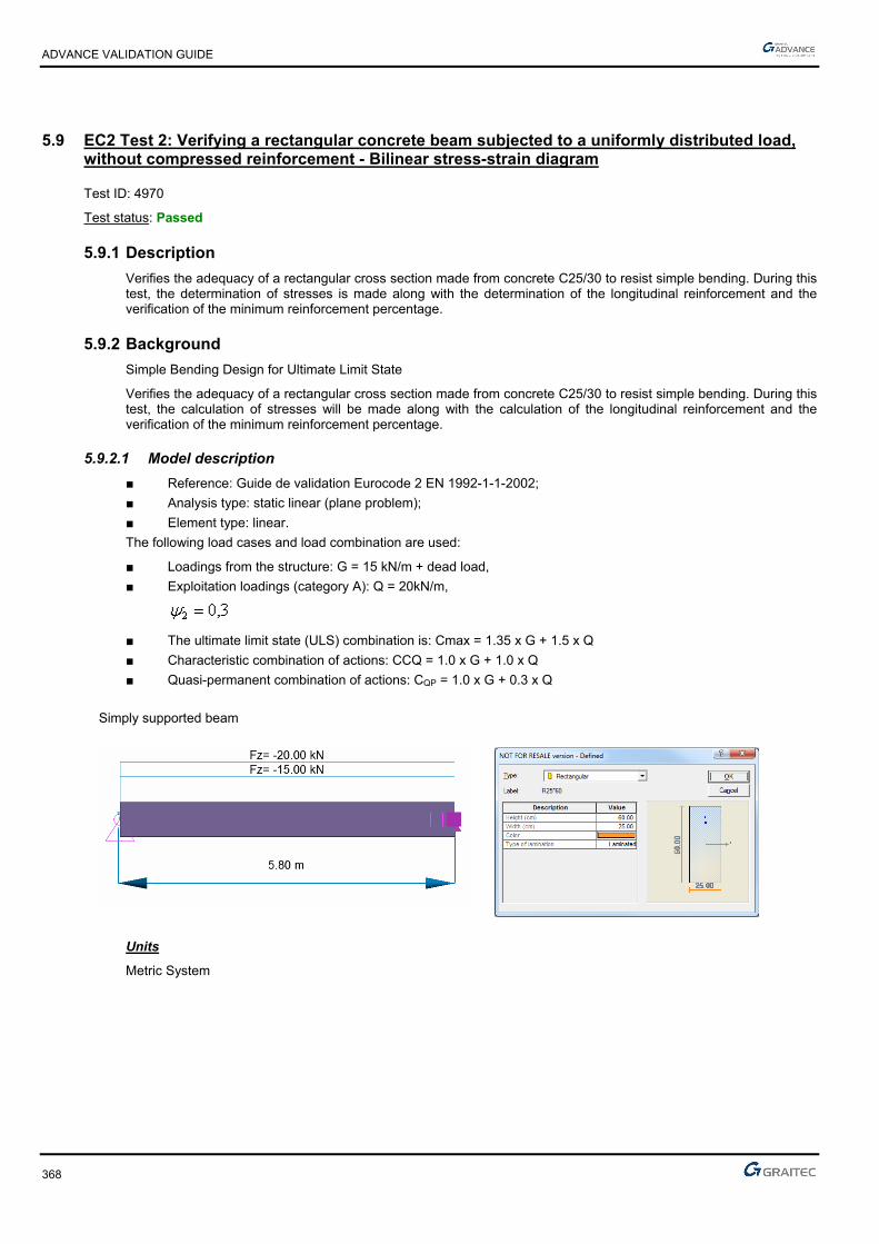
ADVANCE VALIDATION GUIDE
368
5.9 EC2 Test 2: Verifying a rectangular concrete beam subjected to a uniformly distributed load, without compressed reinforcement - Bilinear stress-strain diagram
Test ID: 4970
Test status: Passed
5.9.1 Description
Verifies the adequacy of a rectangular cross section made from concrete C25/30 to resist simple bending. During this test, the determination of stresses is made along with the determination of the longitudinal reinforcement and the verification of the minimum reinforcement percentage.
5.9.2 Background
Simple Bending Design for Ultimate Limit State
Verifies the adequacy of a rectangular cross section made from concrete C25/30 to resist simple bending. During this test, the calculation of stresses will be made along with the calculation of the longitudinal reinforcement and the verification of the minimum reinforcement percentage.
5.9.2.1 Model description
■ Reference: Guide de validation Eurocode 2 EN 1992-1-1-2002;
■ Analysis type: static linear (plane problem);
■ Element type: linear.
The following load cases and load combination are used:
■ Loadings from the structure: G = 15 kN/m + dead load,
■ Exploitation loadings (category A): Q = 20kN/m,
■ The ultimate limit state (ULS) combination is: Cmax = 1.35 x G + 1.5 x Q
■ Characteristic combination of actions: CCQ = 1.0 x G + 1.0 x Q
■ Quasi-permanent combination of actions: CQP = 1.0 x G + 0.3 x Q
Simply supported beam
Units
Metric System
ADVANCE VALIDATION GUIDE
369
Geometry
Beam cross section characteristics:
■ Height: h = 0.60 m,
■ Width: b = 0.25 m,
■ Length: L = 5.80 m,
■ Section area: A = 0.15 m2 ,
■ Concrete cover: c=4.5cm
■ Effective height: d=h-(0.6*h+ebz)=0.519m; d’=ebz=0.045m
Materials properties
Rectangular solid concrete C25/30 and S500A reinforcement steel is used. The following characteristics are used in relation to this material:
■ Exposure class XD1
■ Concrete density: 25kN/m3
■ Stress-strain law for reinforcement: Bilinear stress-strain diagram
■ Cracking calculation required
■ Concrete C25/30: MPa,,
ff
c
ckcd 6716
51
25
γ
According to: EC2 Part 1,1 EN 1992-1-1-2002 Chapter 3.1.6(1); 4.4.2.4(1); Table 2.1.N
■ MPa.*.f*.f //ckctm 56225300300 3232
According to: EC2 Part 1,1 EN 1992-1-1-2002 Chapter 3.1.3(2); Table 3.1
■ Steel S500 : MPa,,
ff
s
ykyd 78434
151
500
γ
According to: EC2 Part 1,1 EN 1992-1-1-2002 Chapter 3.2
■ MPa*f
*E..
ckcm 31476
10
82522000
10
822000
3030
According to: EC2 Part 1,1 EN 1992-1-1-2002 Chapter 3.1.3(2); Table 3.1
Boundary conditions
The boundary conditions are described below:
■ Outer:
► Support at start point (x = 0) restrained in translation along X, Y and Z,
► Support at end point (x = 5.80) restrained in translation along Y, Z and restrained in rotation along X.
■ Inner: None.
ADVANCE VALIDATION GUIDE
370
Loading
The beam is subjected to the following load combinations:
■ Permanent loads:
G’=0.25*0.6*2.5=3.75kN/ml
■ Load combinations:
The ultimate limit state (ULS) combination is:
Cmax = 1.35 x G + 1.5 x Q=1.35*(15+3.75)+1.5*20=55.31kN/ml
Characteristic combination of actions:
CCQ = 1.0 x G + 1.0 x Q=15+3.75+20=38.75kN/ml
Quasi-permanent combination of actions:
CQP = 1.0 x G + 0.3 x Q=15+3.75+0.3*20=24.75kN/ml
■ Load calculations:
mkNMEd .59,2328
²80,5*31,55
mkNMEcq .94,1628
²80,5*75,38
mkNMEqp .07,1048
²80,5*75,24

ADVANCE VALIDATION GUIDE
371
5.9.2.2 Reference results in calculating the equivalent coefficient
To determine the equivalence coefficient, we must first estimate the creep coefficient, related to elastic deformation at 28 days and 50% humidity:
)t(*)f(*)t,( cmRH 00 ββ
According to: EC2 Part 1,1 EN 1992-1-1-2002; Annex B; Chapter B.1(1); B.2
9252825
816816β .
.
f
.)f(
cmcm
According to: EC2 Part 1,1 EN 1992-1-1-2002; Annex B; Chapter B.1(1); B.4
48802810
1
10
1β
2002000
0 ..t.
)t(..
at t0=28 days
According to: EC2 Part 1,1 EN 1992-1-1-2002; Annex B; Chapter B.1(1); B.5
The value of the φRH coefficient depends of the concrete quality:
213
0
αα10
1001
1 **h*.
RH
RH
According to: EC2 Part 1,1 EN 1992-1-1-2002; Annex B; Chapter B.1(1); B.3a
1αα 21 if MPafCM 35
If not:
70
135
α.
cmf
and
20
235
α.
cmf
According to: EC2 Part 1,1 EN 1992-1-1-2002; Annex B; Chapter B.1(1); B.8c
In this case: 1αα338 21 MpaMpaff ckcm
8914717610
100
501
1471766002502
6002502230 .
.*.mm.
)(*
**
u
Ac*h RH
According to: EC2 Part 1,1 EN 1992-1-1-2002; Annex B; Chapter B.1(1); B.6
70248809252891ββ 00 ..*.*.)t(*)f(*)t,( cmRH
The coefficient of equivalence is determined by the following formula:
Ecar
Eqp
cm
se
M
M*)t,(
EE
01
α
Defined earlier:
m.kN,²,*,
MEcar 941628
8057538
m.kN,²,*,
MEqp 071048
8057524
This gives:
32.17
94.162
07.104*70.21
31476200000
e
ADVANCE VALIDATION GUIDE
372
5.9.2.3 Reference results in calculating the concrete beam reduced moment limit
Due to exposure class XD1, we will verify the section having non-compressed steel reinforcement, determining the reduced moment limit, using the formula defined by Jeans Roux in his book “Practice of EC2”:
This value can be determined by the next formula if MPafck 50 valid for a constitutive law to horizontal plateau:
)*..(f*)*..(
f*)(K
ck
ckeluc γ207690159γ701694
αμ
24 αα10α eee *c*ba*K
The values of the coefficients "a", "b" and "c" are defined in the following table:
Diagram for inclined tier Diagram for horizontal plateau
a 8,189*3,75 ckf 108*2,71 ckf
b 5,874*6,5 ckf 4,847*2,5 ckf
c 13*04,0 ckf 5,12*03,0 ckf
This gives us:
■ 188810825*2,71 a
■ 4.7174,84725*2,5 b
■ 75.115,1225*03,0 c
■ 079.1²27.17*75.1127.17*4.717188810 4 eK
Then:
■ 43,194,162
58,232
■ 2504.0)*20.7690.159(*)*70.169.4(
).(
ck
ckeluc f
fK
Reference reinforcement calculation at SLU:
The calculation of the reinforcement is detailed below:
■ Effective height: d=0.9*h=0.53m
■ Calculation of reduced moment:
207,067,16*²519,0*25,0
233,0
*²*
cdw
Edcu fdb
M
■ Calculation of the lever arm zc:
mdz uc 458,0)294,0*4,01(*519,0)*4,01(*
■ Calculation of the reinforcement area:

ADVANCE VALIDATION GUIDE
373
Reference reinforcement calculation at SLS:
We will also conduct a SLS design to ensure that we do not get an upper section of longitudinal reinforcement.
We must determine the position of the neutral axis by calculating (position corresponding to the state of maximum
stress on the concrete and reinforcement).
■ 3940400153217
153217
σσα
σαα1 ,
*.
*.
*
*
sce
ce
rbcqser MkNmM 163, there in no compressed steel reinforcement. This confirms what we previously
found by determining the critical moment limit depending on the coefficient of equivalence and .
Then we calculate the reinforcement resulted from the SLS efforts (assuming the maximum constrain is reached on steel and concrete):
■ Neutral axes position : 394,01
■ Lever arm : mdzc 451.03
394.01*519.0
31* 1
■ Reinforcement section : ²03.9400*451.0
163.0
*,1 cmz
MA
sc
Ecqsers
This shows that the tensile reinforcement obtained in SLS are not dimensioning compared to SLU.
Reference solution for minimal reinforcement area
The minimum percentage for a rectangular beam in pure bending is:
■
d*b*.
d*b*f
f*.
MaxA
w
wyk
eff,ct
min,s
00130
260
According to: EC2 Part 1,1 EN 1992-1-1-2002 Chapter 9.2.1.1(1); Note 2
Where:
MPa.ff ctmeff,ct 562 from cracking conditions
Therefore:
►
²cm.
²m*..*.*.
²m*..*.*.
*.maxA min,s 731
10701519025000130
107315190250500
562260
4
4
Finite elements modeling
■ Linear element: S beam,
■ 7 nodes,
■ 1 linear element.
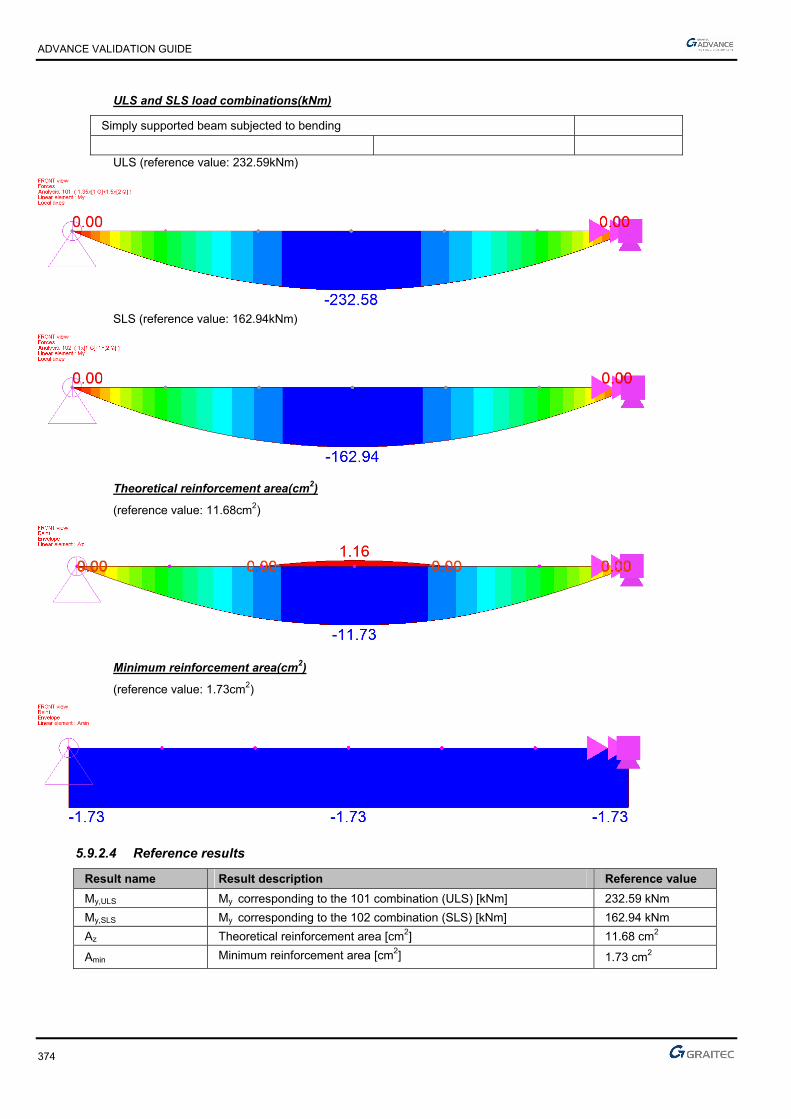
ADVANCE VALIDATION GUIDE
374
ULS and SLS load combinations(kNm)
Simply supported beam subjected to bending
ULS (reference value: 232.59kNm)
SLS (reference value: 162.94kNm)
Theoretical reinforcement area(cm2)
(reference value: 11.68cm2)
Minimum reinforcement area(cm2)
(reference value: 1.73cm2)
5.9.2.4 Reference results
Result name Result description Reference value
My,ULS My corresponding to the 101 combination (ULS) [kNm] 232.59 kNm
My,SLS My corresponding to the 102 combination (SLS) [kNm] 162.94 kNm
Az Theoretical reinforcement area [cm2] 11.68 cm2
Amin Minimum reinforcement area [cm2] 1.73 cm2
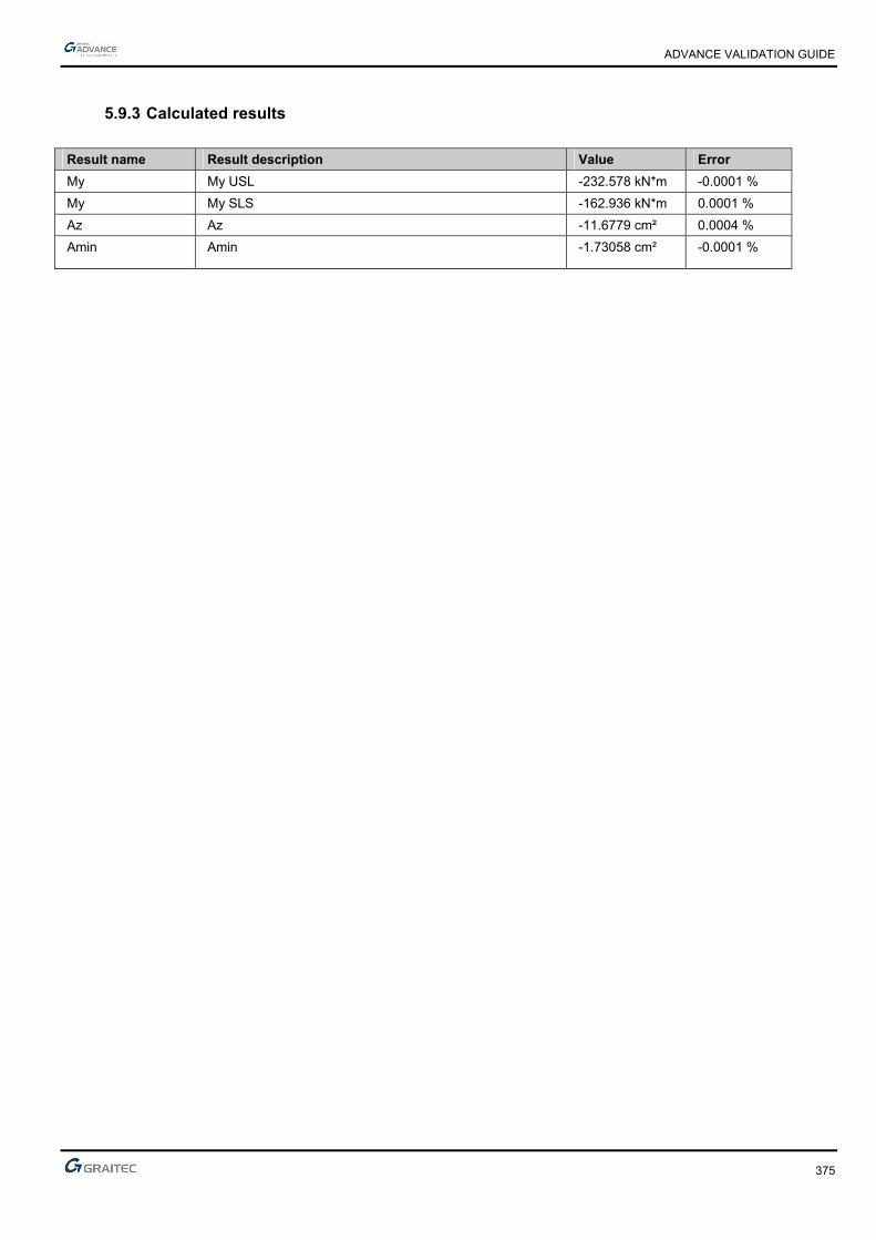
ADVANCE VALIDATION GUIDE
375
5.9.3 Calculated results
Result name Result description Value Error
My My USL -232.578 kN*m -0.0001 %
My My SLS -162.936 kN*m 0.0001 %
Az Az -11.6779 cm² 0.0004 %
Amin Amin -1.73058 cm² -0.0001 %

ADVANCE VALIDATION GUIDE
376
5.10 EC2 Test 4 I: Verifying a rectangular concrete beam subjected to Pivot A efforts – Inclined stress-strain diagram
Test ID: 4977
Test status: Passed
5.10.1 Description
Verifies the adequacy of a rectangular cross section made from concrete C25/30 to resist simple bending. During this test, the determination of stresses is made along with the determination of the longitudinal reinforcement and the verification of the minimum reinforcement percentage.
The purpose of this test is to verify the software results for Pivot A efforts. For these tests, the constitutive law for reinforcement steel, on the inclined stress-strain diagram is applied.
The objective is to verify:
- The stresses results
- The longitudinal reinforcement corresponding to Class A reinforcement steel ductility
- The minimum reinforcement percentage
5.10.2 Background
This test performs the verification of the value (hence the position of the neutral axis) to determine the Pivot efforts (A or B) to be considered for the calculations.
The distinction between the Pivot A and Pivot B efforts is from the following diagram:
ddd
x
cuud
cuu
cuud
cuu .. x 2
2
2
2
The limit for depends of the ductility class:
■ For a Class A steel: 13460α5022ε .. uud
■ For a Class B steel: 0720α45ε .uud
■ For a Class C steel: 0490α5067ε .. uud
The purpose of this test is to verify the software results for Pivot A efforts. For these tests, it will be used the constitutive law for reinforcement steel, on the inclined stress-strain diagram.
MPaAS susu 454.38,95271,432500
MPaBS susu 466.27,72771,432500
MPaCS susu 493.52,89571,432500
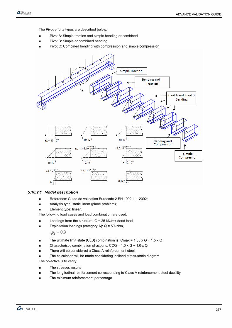
ADVANCE VALIDATION GUIDE
377
The Pivot efforts types are described below:
■ Pivot A: Simple traction and simple bending or combined
■ Pivot B: Simple or combined bending
■ Pivot C: Combined bending with compression and simple compression
5.10.2.1 Model description
■ Reference: Guide de validation Eurocode 2 EN 1992-1-1-2002;
■ Analysis type: static linear (plane problem);
■ Element type: linear.
The following load cases and load combination are used:
■ Loadings from the structure: G = 25 kN/m+ dead load,
■ Exploitation loadings (category A): Q = 50kN/m,
■ The ultimate limit state (ULS) combination is: Cmax = 1.35 x G + 1.5 x Q
■ Characteristic combination of actions: CCQ = 1.0 x G + 1.0 x Q
■ There will be considered a Class A reinforcement steel
■ The calculation will be made considering inclined stress-strain diagram
The objective is to verify:
■ The stresses results
■ The longitudinal reinforcement corresponding to Class A reinforcement steel ductility
■ The minimum reinforcement percentage

ADVANCE VALIDATION GUIDE
378
Simply supported beam
Units
Metric System
Geometry
Below are described the beam cross section characteristics:
■ Height: h = 0.90 m,
■ Width: b = 0.50 m,
■ Length: L = 5.80 m,
■ Section area: A = 0.45 m2 ,
■ Concrete cover: c = 4.00 cm
■ Effective height: d = h - (0.6 * h + ebz)=0.806 m; d’ = ebz = 0.040 m
Materials properties
Rectangular solid concrete C25/30 and S500B reinforcement steel is used. The following characteristics are used in relation to this material:
■ Exposure class XC1
■ Concrete density: 25kN/m3
■ There will be considered a Class A reinforcement steel ductility
■ The calculation will be made considering inclined stress-strain diagram
■ Cracking calculation required
■ Concrete C25/30: MPa,,
ff
c
ckcd 6716
51
25
γ
According to: EC2 Part 1,1 EN 1992-1-1-2002 Chapter 3.1.6(1); 4.4.2.4(1); Table 2.1.N
■ MPa.*.f*.f //ckctm 56225300300 3232
According to: EC2 Part 1,1 EN 1992-1-1-2002 Chapter 3.1.3(2); Table 3.1
■ Steel S500 : MPa,,
ff
s
ykyd 78434
151
500
γ
According to: EC2 Part 1,1 EN 1992-1-1-2002 Chapter 3.2
Boundary conditions
The boundary conditions are described below:
■ Outer:
► Support at start point (x=0) restrained in translation along X, Y and Z,
► Support at end point (x = 5.8) restrained in translation along Y and Z, and restrained rotation along X.
■ Inner: None.

ADVANCE VALIDATION GUIDE
379
Loading
The beam is subjected to the following load combinations:
Dead load:
G’=0.9*0.5*2.5=11.25 kN/ml
Load combinations:
■ The ultimate limit state (ULS) combination is:
Cmax = 1.35 x G + 1.5 x Q=1.35*(25+11.25)+1.5*50=123.94 kN/ml
■ Characteristic combination of actions:
CCQ = 1.0 x G + 1.0 x Q=25+11.25+50=86.25kN/ml
■ Load calculations:
kNmMEd 16.5218
²80.5*94.123
kNmMEcq 68.3628
²80.5*25.86
5.10.2.2 Reference results in calculating the concrete beam reduced moment limit
For a S500B reinforcement steel, we have 372.0lu (since we consider no limit on the compression concrete to
SLS).
Reference reinforcement calculation:
The calculation of the reinforcement is detailed below:
■ Effective height: d=h-(0.6*h+ebz)=0.806 m
■ Calculation of reduced moment:
096,067,16*²806.0*50,0
10*52116.0
*²* 2
3
MPamm
Nm
fdb
M
cdw
Edcu
■ The α value:
■ The condition: 13460αα .ucu is satisfied, therefore the Pivot A effort conditions are true
There will be a design in simple bending, by considering an extension on the reinforced steel tension equal to
5022ε .ud
, which gives the following available stress:
■ MPa.,,AS su 454022503895271432σ500

ADVANCE VALIDATION GUIDE
380
The calculation of the concrete shortening:
27.3
127.01
127.0*50.22
1*
cu
cusucu
It is therefore quite correct to consider a design stress of concrete equal to cdf .
mdz cuc 765.0)127.0*4.01(*806.0)*4,01(*
²00.15454*765.0
52116.0
*cm
fz
MA
ydc
Edu
Reference solution for minimal reinforcement area
The minimum percentage for a rectangular beam in pure bending is:
db
dbf
f
MaxA
w
wyk
effct
s
**0013.0
***26.0 ,
min,
According to: EC2 Part 1,1 EN 1992-1-1-2002 Chapter 9.2.1.1(1); Note 2
Where:
MPaff ctmeffct 56.2, from cracking conditions
Therefore:
²38.5²10*24.5806.0*50.0*0013.0
²10*38.5806.0*50.0*500
56.2*26.0
max4
4
min, cmm
mAs
Finite elements modeling
■ Linear element: S beam,
■ 7 nodes,
■ 1 linear element.

ADVANCE VALIDATION GUIDE
381
ULS and SLS load combinations (kNm)
Simply supported beam subjected to bending
ULS (reference value: 521.16kNm)
SLS (reference value: 362.68kNm)
Theoretical reinforcement area (cm2)
For Class A reinforcement steel ductility (reference value: A=15.00cm2)
Minimum reinforcement area(cm2)
(reference value: 5.38cm2)

ADVANCE VALIDATION GUIDE
382
5.10.2.3 Reference results
Result name Result description Reference value
My,ULS My corresponding to the 101 combination (ULS) [kNm] 521.16 kNm
My,SLS My corresponding to the 102 combination (SLS) [kNm] 362.68 kNm
Az Theoretical reinforcement area (Class A) [cm2] 15.00 cm2
Amin Minimum reinforcement area [cm2] 5.38 cm2
5.10.3 Calculated results
Result name Result description Value Error
My My USL -521.125 kN*m 0.0000 %
My My SLS -362.657 kN*m -0.0001 %
Az Az Class A -14.9973 cm² -0.0001 %
Az Az Class B -14.9973 cm² 0.7491 %
Amin Amin -5.37514 cm² 0.0000 %
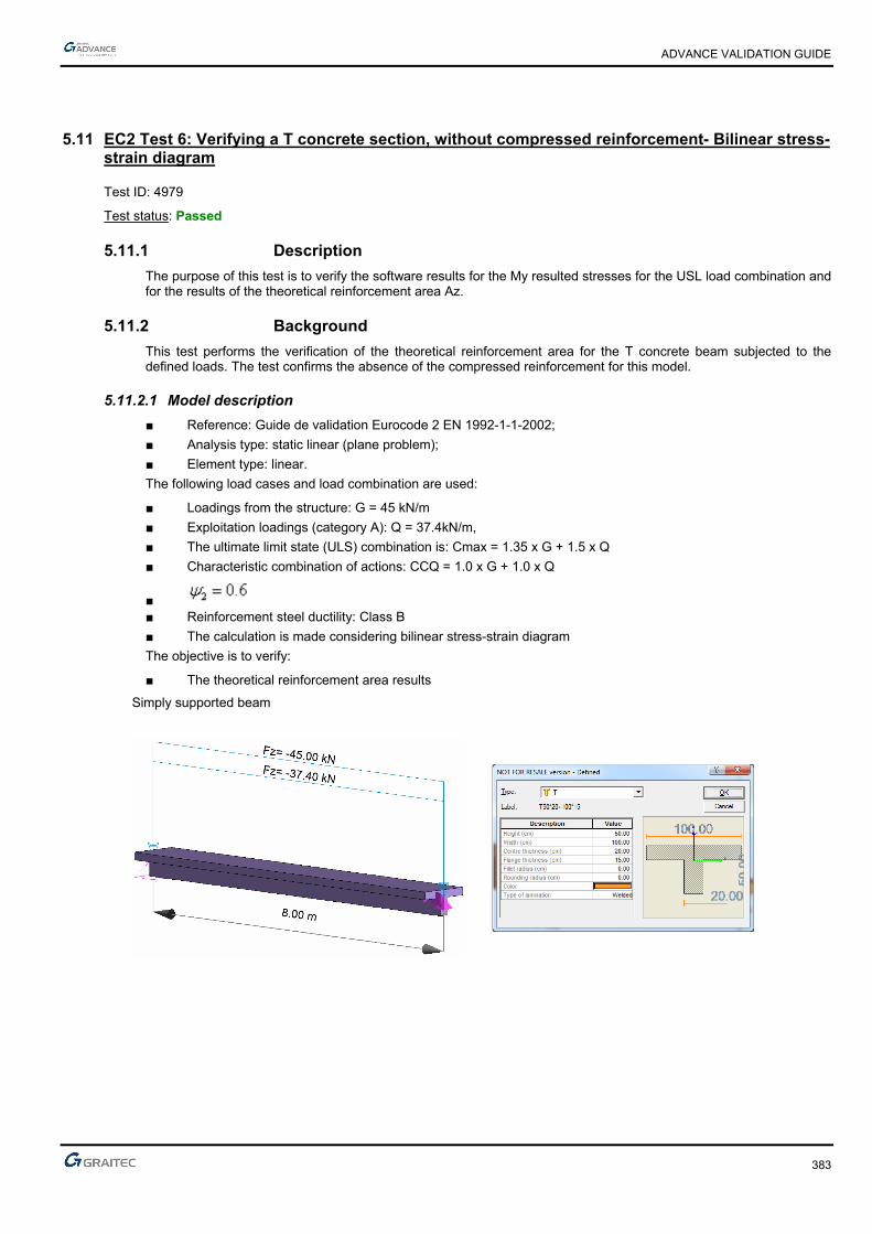
ADVANCE VALIDATION GUIDE
383
5.11 EC2 Test 6: Verifying a T concrete section, without compressed reinforcement- Bilinear stress-strain diagram
Test ID: 4979
Test status: Passed
5.11.1 Description
The purpose of this test is to verify the software results for the My resulted stresses for the USL load combination and for the results of the theoretical reinforcement area Az.
5.11.2 Background
This test performs the verification of the theoretical reinforcement area for the T concrete beam subjected to the defined loads. The test confirms the absence of the compressed reinforcement for this model.
5.11.2.1 Model description
■ Reference: Guide de validation Eurocode 2 EN 1992-1-1-2002;
■ Analysis type: static linear (plane problem);
■ Element type: linear.
The following load cases and load combination are used:
■ Loadings from the structure: G = 45 kN/m
■ Exploitation loadings (category A): Q = 37.4kN/m,
■ The ultimate limit state (ULS) combination is: Cmax = 1.35 x G + 1.5 x Q
■ Characteristic combination of actions: CCQ = 1.0 x G + 1.0 x Q
■ ■ Reinforcement steel ductility: Class B
■ The calculation is made considering bilinear stress-strain diagram
The objective is to verify:
■ The theoretical reinforcement area results
Simply supported beam

ADVANCE VALIDATION GUIDE
384
Units
Metric System
Geometry
Beam cross section characteristics:
■ Beam length: 8m
■ Concrete cover: c=3.50 cm
■ Effective height: d=h-(0.6*h+ebz)=0.435 m; d’=ebz=0.035m
Materials properties
Rectangular solid concrete C25/30 and S500B reinforcement steel is used. The following characteristics are used in relation to this material:
■ Exposure class XC1
■ Concrete density: 25kN/m3
■ Reinforcement steel ductility: Class B
■ The calculation is made considering bilinear stress-strain diagram
■ Concrete C25/30: MPaf
fc
ckcd 67.10
5,1
25
According to: EC2 Part 1,1 EN 1992-1-1-2002 Chapter 3.1.6(1); 4.4.2.4(1); Table 2.1.N
■ MPaff ckctm 56.225*30.0*30.0 3/23/2
According to: EC2 Part 1,1 EN 1992-1-1-2002 Chapter 3.1.3(2); Table 3.1
■ Steel S500B : MPaf
fs
ykyd 78.434
15,1
500
According to: EC2 Part 1,1 EN 1992-1-1-2002 Chapter 3.2
Boundary conditions
The boundary conditions are described below:
■ Outer:
► Support at start point (x=0) restrained in translation along X, Y and Z,
► Support at end point (x = 8) restrained in translation along Y and Z, and restrained rotation along X.
■ Inner: None.

ADVANCE VALIDATION GUIDE
385
Loading
The beam is subjected to the following load combinations:
■ Load combinations:
The ultimate limit state (ULS) combination is:
Cmax = 1.35 x G + 1.5 x Q=1.35*45+1.5*37.4=116.85kN/ml
Characteristic combination of actions:
CCQ = 1.0 x G + 1.0 x Q=45+34.7=79.7kN/ml
■ Load calculations:
kNmMEd 8.9348
²8*85.116
5.11.2.2 Reference results in calculating the concrete beam moment
At first it will be determined the moment resistance of the concrete section only:
kNmfh
dhbM cdf
feffbtu 967.16*2
15.0435.0*15.0*00.1*
2**
Comparing Mbtu with MEd:
Therefore, the concrete section is not entirely compressed;
Therefore, the calculations considering the T section are required.
5.11.2.3 Reference reinforcement calculation:
Theoretical section 2:
The moment corresponding to this section is:
kNm
hdfhbbM f
cdfweffEd
720
2
15.0435.0*67.16*15.0*)20.01(
2***)(2
According to this value, the steel section is:
²00.468.347*
2
15.0435.0
720.0
*2
22 cm
fh
d
MA
ydf
Ed
Theoretical section 1:
The theoretical section 1 corresponds to a calculation for a rectangular shape beam section.
kNmMMM EdEdEd 21572093521
341.067.16*²435.0*20.0
215.0
*²*1
cdw
Edcu Fdb
M
kNmMkNmM Edbtu 8.934900
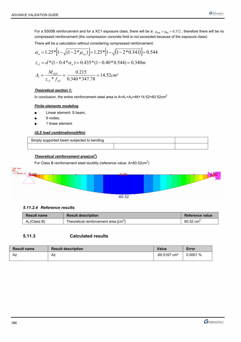
ADVANCE VALIDATION GUIDE
386
For a S500B reinforcement and for a XC1 exposure class, there will be a: 3720μμ .lucu , therefore there will be no
compressed reinforcement (the compression concrete limit is not exceeded because of the exposure class)
There will be a calculation without considering compressed reinforcement:
544.0341.0*211*25.1)*21(1*25.1 cuu
mdz uc 340.0)544.0*40.01(*435.0)*4.01(*1
²52.1478.347*340.0
215.0
*1
11 cm
fz
MA
ydc
Ed
Theoretical section 1:
In conclusion, the entire reinforcement steel area is A=A1+A2=46+14.52=60.52cm2
Finite elements modeling
■ Linear element: S beam,
■ 9 nodes,
■ 1 linear element.
ULS load combinations(kNm)
Simply supported beam subjected to bending
Theoretical reinforcement area(cm2)
For Class B reinforcement steel ductility (reference value: A=60.52cm2)
5.11.2.4 Reference results
Result name Result description Reference value
Az (Class B) Theoretical reinforcement area [cm2] 60.52 cm2
5.11.3 Calculated results
Result name Result description Value Error
Az Az -60.5167 cm² 0.0001 %
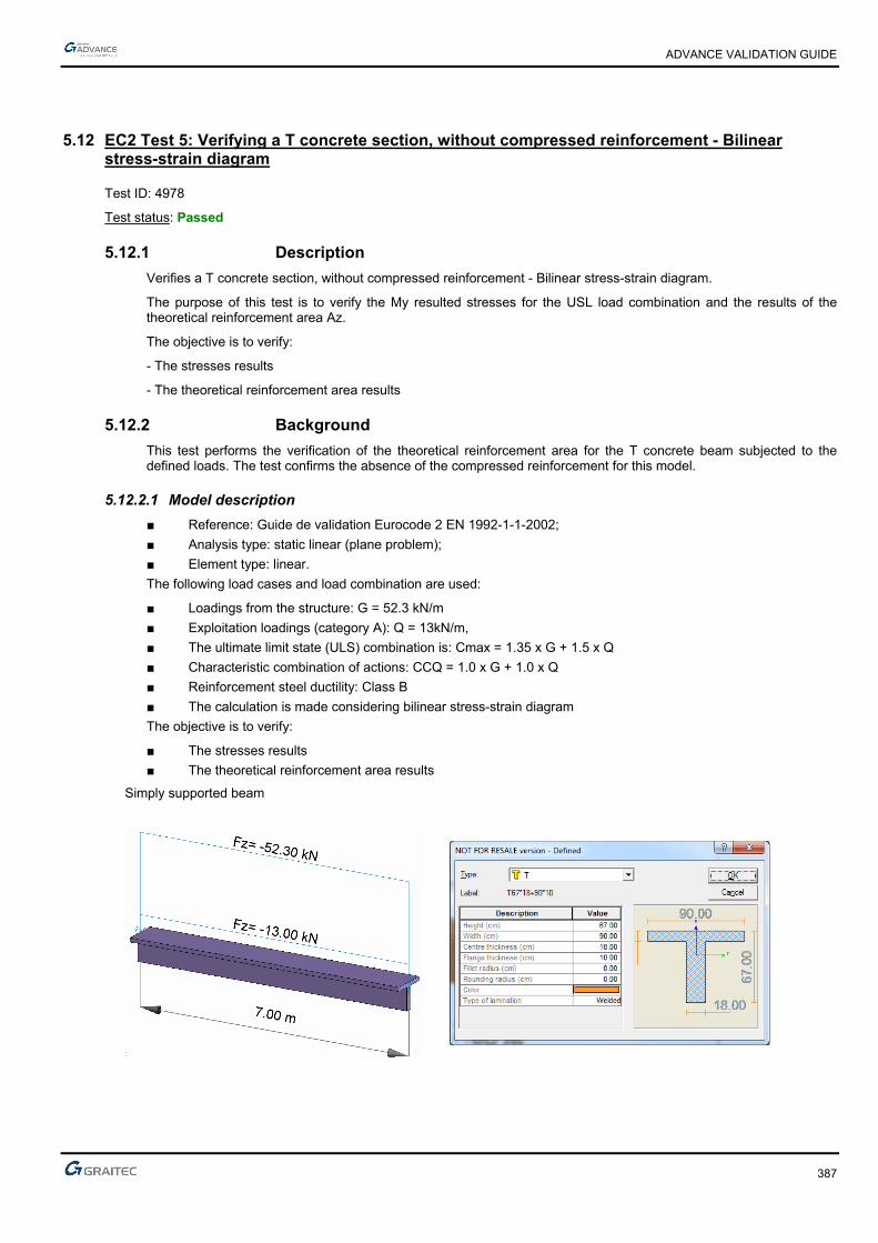
ADVANCE VALIDATION GUIDE
387
5.12 EC2 Test 5: Verifying a T concrete section, without compressed reinforcement - Bilinear stress-strain diagram
Test ID: 4978
Test status: Passed
5.12.1 Description
Verifies a T concrete section, without compressed reinforcement - Bilinear stress-strain diagram.
The purpose of this test is to verify the My resulted stresses for the USL load combination and the results of the theoretical reinforcement area Az.
The objective is to verify:
- The stresses results
- The theoretical reinforcement area results
5.12.2 Background
This test performs the verification of the theoretical reinforcement area for the T concrete beam subjected to the defined loads. The test confirms the absence of the compressed reinforcement for this model.
5.12.2.1 Model description
■ Reference: Guide de validation Eurocode 2 EN 1992-1-1-2002;
■ Analysis type: static linear (plane problem);
■ Element type: linear.
The following load cases and load combination are used:
■ Loadings from the structure: G = 52.3 kN/m
■ Exploitation loadings (category A): Q = 13kN/m,
■ The ultimate limit state (ULS) combination is: Cmax = 1.35 x G + 1.5 x Q
■ Characteristic combination of actions: CCQ = 1.0 x G + 1.0 x Q
■ Reinforcement steel ductility: Class B
■ The calculation is made considering bilinear stress-strain diagram
The objective is to verify:
■ The stresses results
■ The theoretical reinforcement area results
Simply supported beam

ADVANCE VALIDATION GUIDE
388
Units
Metric System
Geometry
Beam cross section characteristics:
■ Beam length: 7m
■ Concrete cover: c=3.50 cm
■ Effective height: d=h-(0.6*h+ebz)=0.595 m; d’=ebz=0.035m
Materials properties
Rectangular solid concrete C16/20 and S400B reinforcement steel is used. The following characteristics are used in relation to this material:
■ Exposure class XC1
■ Concrete density: 16kN/m3
■ Reinforcement steel ductility: Class A
■ The calculation is made considering bilinear stress-strain diagram
■ Concrete C16/20: MPaf
fc
ckcd 67.10
5,1
16
According to: EC2 Part 1,1 EN 1992-1-1-2002 Chapter 3.1.6(1); 4.4.2.4(1); Table 2.1.N
■ MPa.*.f*.f //ckctm 90116300300 3232
According to: EC2 Part 1,1 EN 1992-1-1-2002 Chapter 3.1.3(2); Table 3.1
■ Steel S400B : MPaf
fs
ykyd 8.347
15,1
400
According to: EC2 Part 1,1 EN 1992-1-1-2002 Chapter 3.2
Boundary conditions
The boundary conditions are described below:
■ Outer:
► Support at start point (x=0) restrained in translation along X, Y and Z,
► Support at end point (x = 7) restrained in translation along Y and Z, and restrained rotation along X.
■ Inner: None.

ADVANCE VALIDATION GUIDE
389
Loading
The beam is subjected to the following load combinations:
■ Load combinations:
The ultimate limit state (ULS) combination is:
Cmax = 1.35 x G + 1.5 x Q=1.35*352.3+1.5*13=90.105kN/ml
Characteristic combination of actions:
CCQ = 1.0 x G + 1.0 x Q=52.3+13=65.3kN/ml
Load calculations:
kNmMEd 89.5518
²7*105.70
kNmMEcq 96.3998
²7*3.65
5.12.2.2 Reference results in calculating the concrete beam moment
At first, it will be determined the moment resistance of the concrete section only:
kNm,*,
,*,*,f*h
d*h*bM cdf
feffbtu 52367102
100595010090
2
Comparing Mbtu with MEd:
Therefore the concrete section is not entirely compressed;
Therefore, calculations considering the T section are required.
5.12.2.3 Reference reinforcement calculation:
Theoretical section 2:
■ The moment corresponding to this section is:
MNm
hdfhbbM f
cdfweffEd
418.0
2
1.00595*67.10*1.0*)18.09.0(
2***)(2
■ According to this value, the steel section is:
²08.228.347*
2
1.0595.0
418.0
*2
22 cm
fh
d
MA
ydf
Ed
kNmMkNmM Edbtu 89.551523
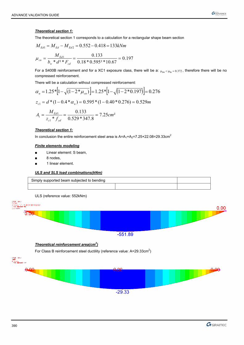
ADVANCE VALIDATION GUIDE
390
Theoretical section 1:
The theoretical section 1 corresponds to a calculation for a rectangular shape beam section
kNmMMM EdEdEd 133418.0552.021
197.067.10*²595.0*18.0
133.0
*²*1
cdw
Edcu Fdb
M
For a S400B reinforcement and for a XC1 exposure class, there will be a: 3720μμ .lucu , therefore there will be no
compressed reinforcement.
There will be a calculation without compressed reinforcement:
276.0197.0*211*25.1)*21(1*25.1 cuu
mdz uc 529.0)276.0*40.01(*595.0)*4.01(*1
²25.78.347*529.0
133.0
*1
11 cm
fz
MA
ydc
Ed
Theoretical section 1:
In conclusion the entire reinforcement steel area is A=A1+A2=7.25+22.08=29.33cm2
Finite elements modeling
■ Linear element: S beam,
■ 8 nodes,
■ 1 linear element.
ULS and SLS load combinations(kNm)
Simply supported beam subjected to bending
ULS (reference value: 552kNm)
Theoretical reinforcement area(cm2)
For Class B reinforcement steel ductility (reference value: A=29.33cm2)

ADVANCE VALIDATION GUIDE
391
5.12.2.4 Reference results
Result name Result description Reference value
My,ULS My corresponding to the 101 combination (ULS) [kNm] 552 kNm
Az (Class B) Theoretical reinforcement area [cm2] 29.33 cm2
5.12.3 Calculated results
Result name Result description Value Error
My My USL -551.893 kN*m -0.0000 %
Az Az -29.3334 cm² 0.0002 %

ADVANCE VALIDATION GUIDE
392
5.13 EC2 Test 8: Verifying a rectangular concrete beam without compressed reinforcement – Inclined stress-strain diagram
Test ID: 4981
Test status: Passed
5.13.1 Description
Verifies the adequacy of a rectangular cross section made from concrete C30/37 to resist simple bending. During this test, the determination of stresses is made along with the determination of the longitudinal reinforcement and the verification of the minimum reinforcement percentage.
The purpose of the test is to verify the results using a constitutive law for reinforcement steel, on the inclined stress-strain diagram.
The objective is to verify:
- The stresses results
- The longitudinal reinforcement corresponding to Class A reinforcement steel ductility
- The minimum reinforcement percentage
5.13.2 Background
Verifies the adequacy of a rectangular cross section made from concrete C30/37 to resist simple bending. During this test, the calculation of stresses is made along with the calculation of the longitudinal reinforcement and the verification of the minimum reinforcement percentage.
The purpose of this test is to verify the software results for using a constitutive law for reinforcement steel, on the inclined stress-strain diagram.
5.13.2.1 Model description
■ Reference: Guide de validation Eurocode 2 EN 1992-1-1-2002;
■ Analysis type: static linear (plane problem);
■ Element type: linear.
The following load cases and load combination are used:
■ Loadings from the structure: G = 25 kN/m (including the dead load)
■ Exploitation loadings (category A): Q = 30kN/m,
■ ■ The ultimate limit state (ULS) combination is: Cmax = 1.35 x G + 1.5 x Q
■ Characteristic combination of actions: CCQ = 1.0 x G + 1.0 x Q
■ Quasi-permanent combination of actions: CQP = 1.0 x G + 0.6 x Q
■ Reinforcement steel: Class A
■ The calculation is performed considering inclined stress-strain diagram
■ Cracking calculation required
The objective is to verify:
■ The stresses results
■ The longitudinal reinforcement corresponding to doth Class A reinforcement steel ductility
■ The minimum reinforcement percentage

ADVANCE VALIDATION GUIDE
393
Simply supported beam
Units
Metric System
Geometry
Beam cross section characteristics:
■ Height: h = 0.65 m,
■ Width: b = 0.28 m,
■ Length: L = 6.40 m,
■ Section area: A = 0.182 m2 ,
■ Concrete cover: c=4.50 cm
■ Effective height: d=h-(0.6*h+ebz)=0.806 m; d’=ebz=0.045m
Materials properties
Rectangular solid concrete C30/37 and S500A reinforcement steel is used. The following characteristics are used in relation to this material:
■ Exposure class XD3
■ Concrete density: 25kN/m3
■ Reinforcement steel ductility: Class A
■ The calculation is performed considering inclined stress-strain diagram
■ Cracking calculation required
■ Concrete C25/30: MPaf
fc
ckcd 20
5,1
30
According to: EC2 Part 1,1 EN 1992-1-1-2002 Chapter 3.1.6(1); 4.4.2.4(1); Table 2.1.N
■ MPaff ckctm 90.230*30.0*30.0 3/23/2
According to: EC2 Part 1,1 EN 1992-1-1-2002 Chapter 3.1.3(2); Table 3.1
■ MPa*f
*E..
ckcm 32837
10
83022000
10
822000
3030
■ Steel S500 : MPa,,
ff
s
ykyd 78434
151
500
γ
According to: EC2 Part 1,1 EN 1992-1-1-2002 Chapter 3.2

ADVANCE VALIDATION GUIDE
394
Boundary conditions
The boundary conditions are described below:
■ Outer:
► Support at start point (x=0) restrained in translation along X, Y and Z,
► Support at end point (x = 6.40) restrained in translation along Y and Z, and restrained rotation along X.
■ Inner: None.
Loading
The beam is subjected to the following load combinations:
■ Load combinations:
The ultimate limit state (ULS) combination is:
Cmax = 1.35 x G + 1.5 x Q=1.35*(25)+1.5*30=78.75kN/ml
Characteristic combination of actions:
CCQ = 1.0 x G + 1.0 x Q=25+30=55kN/ml
Quasi-permanent combination of actions:
CQP = 1.0 x G + 0.6 x Q=25+0.6*30=43kNm
■ Load calculations:
kNmMEd 20.4038
²40.6*75.78
kNmMEcq 60.2818
²40.6*55
kNmMEqp 16.2208
²40.6*43

ADVANCE VALIDATION GUIDE
395
5.13.2.2 Reference results in calculating the equivalent coefficient
To determine the equivalence coefficient, we must first estimate the creep coefficient, related to elastic deformation at 28 days and 50% humidity:
)(*)(*),( 00 tft cmRH
According to: EC2 Part 1,1 EN 1992-1-1-2002; Annex B; Chapter B.1(1); B.2
According to: EC2 Part 1,1 EN 1992-1-1-2002; Annex B; Chapter B.1(1); B.4
at t0=28 days
According to: EC2 Part 1,1 EN 1992-1-1-2002; Annex B; Chapter B.1(1); B.5
The value of the φRH coefficient depends of the concrete quality:
213
0
αα10
1001
1 **h*.
RH
RH
According to: EC2 Part 1,1 EN 1992-1-1-2002; Annex B; Chapter B.1(1); B.3a
1αα 21 if MPafCM 35
If not:
70
135
α.
cmf
and
20
235
α.
cmf
According to: EC2 Part 1,1 EN 1992-1-1-2002; Annex B; Chapter B.1(1); B.8c
In this case, MpaMpaff ckcm 388
944038
3535α
7070
1 .f
..
cm
984038
3535α
2020
2 .f
..
cm
7819840719510
100
501
171956502802
6502802230 ..*
.*.mm.
)(*
**
u
Ac*h RH
According to: EC2 Part 1,1 EN 1992-1-1-2002; Annex B; Chapter B.1(1); B.6
3724880732781ββ 00 ..*.*.)t(*)f(*)t,( cmRH
The coefficient of equivalence is determined using the following formula:
4017
60281
162203721
32837200000
1
α
0
.
.
.*.
M
M*)t,(
EE
Ecar
Eqp
cm
se

ADVANCE VALIDATION GUIDE
396
5.13.2.3 Reference results in calculating the concrete beam reduced moment limit
Due to exposure class XD3, we will verify the section having non-compressed steel reinforcement, determining the reduced moment limit, using the formula defined by Jeans Roux in his book “Practice of EC2”:
This value can be determined by the next formula if MPafck 50 and valid for a constitutive law considering
inclined stress-strain diagram:
)*62.7969.165(*)*66.162.4(*)(
ck
ckeluc f
fK
24 ***10 eee cbaK
The values of the coefficients "a", "b" and "c" are defined in the following table:
Diagram for inclined stress-strain diagram Diagram for bilinear stress-strain diagram
a 8,189*3,75 ckf 108*2,71 ckf
b 5,874*6,5 ckf 4,847*2,5 ckf
c 13*04,0 ckf 5,12*03,0 ckf
This gives us:
22069818925375 ..*.a
570658743025 ..*,b
8111330040 .*,c
087.1²60.17*80.1160.17*5.7062.206910 4 eK
Then:
425,12.307
76.437
272.0)*62.7969.165(*)*66.162.4(
).(
ck
ckeluc f
fK
Calculation of reduced moment:
225,020*²566.0*50,0
10*403.0
*²* 2
3
MPamm
Nm
fdb
M
cdw
Edcu
272.0225.0 luccu therefore, there is no compressed reinforcement
Reference reinforcement calculation at SLS:
The calculation of the reinforcement is detailed below:
■ Effective height: d = 0.566m
■ Calculation of reduced moment:
225.0cu
■ Calculation of the lever arm zc:
mdz uc 493,0)323,0*4,01(*566,0)*4,01(*

ADVANCE VALIDATION GUIDE
397
■ Calculation of the reinforcement area:
²68,11²10*68,1178,434*458,0
233,0
*4 cmm
fz
MA
ydc
Edu
■ Calculation of the stresses from the tensioned reinforcement:
Reinforcement steel elongation:
35.75.3*323,0
323,01*
12
cu
u
usu
‰
Tensioned reinforcement efforts:
MPaMPasusu 45471.43900735.0*38,95271,432*38,95271,432
■ Reinforcement section calculation:
²60.18²10*60.1871.439*493.0
403.0
*4 cmm
fz
MA
ydc
Edu
Reference solution for minimal reinforcement area
The minimum percentage for a rectangular beam in pure bending is:
d*b*.
d*b*f
f*.
MaxA
w
wyk
eff,ct
min,s
00130
260
According to: EC2 Part 1,1 EN 1992-1-1-2002 Chapter 9.2.1.1(1); Note 2
Where:
MPa.ff ctmeff,ct 902 from cracking conditions
Therefore:
²39.2²10*06.2566.0*28.0*0013.0
²10*39.2566.0*28.0*500
90.2*26.0
max4
4
min, cmm
mAs
Finite elements modeling
■ Linear element: S beam,
■ 7 nodes,
■ 1 linear element.
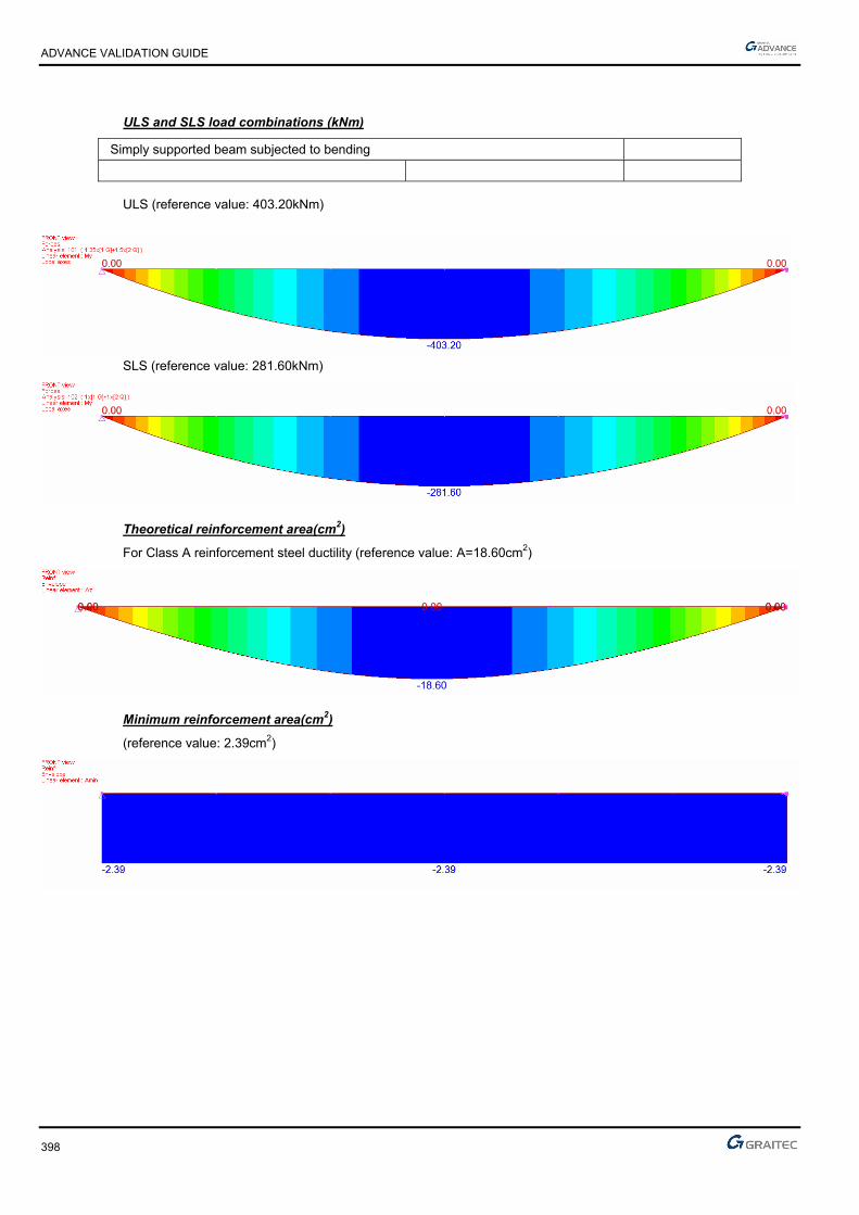
ADVANCE VALIDATION GUIDE
398
ULS and SLS load combinations (kNm)
Simply supported beam subjected to bending
ULS (reference value: 403.20kNm)
SLS (reference value: 281.60kNm)
Theoretical reinforcement area(cm2)
For Class A reinforcement steel ductility (reference value: A=18.60cm2)
Minimum reinforcement area(cm2)
(reference value: 2.39cm2)

ADVANCE VALIDATION GUIDE
399
5.13.2.4 Reference results
Result name Result description Reference value
My,ULS My corresponding to the 101 combination (ULS) [kNm] 403.20 kNm
My,SLS My corresponding to the 102 combination (SLS) [kNm] 281.60 kNm
Az (Class A) Theoretical reinforcement area [cm2] 18.60 cm2
Amin Minimum reinforcement area [cm2] 2.39 cm2
5.13.3 Calculated results
Result name Result description Value Error
My My USL -403.2 kN*m 0.0000 %
My My SLS -281.6 kN*m 0.0000 %
Az Az -18.6006 cm² -0.0001 %
Amin Amin -2.38697 cm² 0.0001 %
ADVANCE VALIDATION GUIDE
400
5.14 EC2 Test 9: Verifying a rectangular concrete beam with compressed reinforcement – Inclined stress-strain diagram
Test ID: 4982
Test status: Passed
5.14.1 Description
Verifies the adequacy of a rectangular cross section made from concrete C25/30 to resist simple bending. During this test, the determination of stresses is made along with the determination of the longitudinal reinforcement and the verification of the minimum reinforcement percentage.
For these tests, the constitutive law for reinforcement steel, on the inclined stress-strain diagram is applied.
This test performs the verification of the theoretical reinforcement area for a rectangular concrete beam subjected to the defined loads. The test confirms the presence of the compressed reinforcement for this model.
5.14.2 Background
Verifies the adequacy of a rectangular cross section made from concrete C25/30 to resist simple bending. During this test, the calculation of stresses, the calculation of the longitudinal reinforcement and the verification of the minimum reinforcement percentage are performed.
For these tests, the constitutive law for reinforcement steel, on the inclined stress-strain diagram is applied.
This test performs the verification of the theoretical reinforcement area for a rectangular concrete beam subjected to the defined loads. The test confirms the presence of the compressed reinforcement for this model.
5.14.2.1 Model description
■ Reference: Guide de validation Eurocode 2 EN 1992-1-1-2002;
■ Analysis type: static linear (plane problem);
■ Element type: linear.
The following load cases and load combination are used:
■ Linear loadings :
Loadings from the structure: G = 55 kN/m+ dead load,
Live loads: Q=60kN/m
■ Point loads:
Loadings from the structure: G = 35kN;
Live loads: Q=25kN
■ 8,02
■ The ultimate limit state (ULS) combination is: Cmax = 1.35 x G + 1.5 x Q
■ Characteristic combination of actions: CCQ = 1.0 x G + 1.0 x Q
■ Quasi-permanent combination of actions: CQP = 1.0 x G + 0.6 x Q
■ Reinforcement steel ductility: Class A
■ The calculation is performed considering inclined stress-strain diagram
The objective is to verify:
■ The stresses results
■ The longitudinal reinforcement
■ The minimum reinforcement percentage

ADVANCE VALIDATION GUIDE
401
Simply supported beam
Units
Metric System
Geometry
Below are described the beam cross section characteristics:
■ Height: h = 0.80 m,
■ Width: b = 0.40 m,
■ Length: L = 6.30 m,
■ Section area: A = 0.32 m2 ,
■ Concrete cover: c=4.50 cm
■ Effective height: d=h-(0.6*h+ebz)=0.707 m; d’=ebz=0.045m
Materials properties
Rectangular solid concrete C25/30 and S500A reinforcement steel is used. The following characteristics are used in relation to this material:
■ Exposure class XD1
■ Concrete density: 25kN/m3
■ Reinforcement steel ductility: Class A
■ The calculation is performed considering inclined stress-strain diagram
■ Cracking calculation required
■ Concrete C25/30:
MPa,,
ff
c
ckcd 6716
51
25
γ
According to: EC2 Part 1,1 EN 1992-1-1-2002 Chapter 3.1.6(1); 4.4.2.4(1); Table 2.1.N
According to: EC2 Part 1,1 EN 1992-1-1-2002 Chapter 3.1.3(2); Table 3.1
MPaf
E ckcm 31476
10
82522000
10
822000
3.03.0
■ Steel S500 :
According to: EC2 Part 1,1 EN 1992-1-1-2002 Chapter 3.2
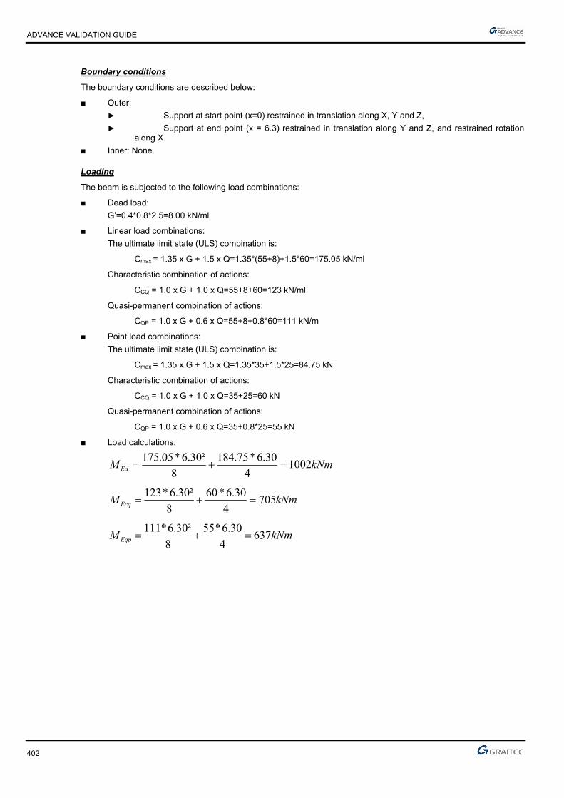
ADVANCE VALIDATION GUIDE
402
Boundary conditions
The boundary conditions are described below:
■ Outer:
► Support at start point (x=0) restrained in translation along X, Y and Z,
► Support at end point (x = 6.3) restrained in translation along Y and Z, and restrained rotation along X.
■ Inner: None.
Loading
The beam is subjected to the following load combinations:
■ Dead load:
G’=0.4*0.8*2.5=8.00 kN/ml
■ Linear load combinations:
The ultimate limit state (ULS) combination is:
Cmax = 1.35 x G + 1.5 x Q=1.35*(55+8)+1.5*60=175.05 kN/ml
Characteristic combination of actions:
CCQ = 1.0 x G + 1.0 x Q=55+8+60=123 kN/ml
Quasi-permanent combination of actions:
CQP = 1.0 x G + 0.6 x Q=55+8+0.8*60=111 kN/m
■ Point load combinations:
The ultimate limit state (ULS) combination is:
Cmax = 1.35 x G + 1.5 x Q=1.35*35+1.5*25=84.75 kN
Characteristic combination of actions:
CCQ = 1.0 x G + 1.0 x Q=35+25=60 kN
Quasi-permanent combination of actions:
CQP = 1.0 x G + 0.6 x Q=35+0.8*25=55 kN
■ Load calculations:
kNmMEd 10024
30.6*75.184
8
²30.6*05.175
kNmMEcq 7054
30.6*60
8
²30.6*123
kNmMEqp 6374
30.6*55
8
²30.6*111

ADVANCE VALIDATION GUIDE
403
5.14.2.2 Reference results in calculating the equivalent coefficient
To determine the equivalence coefficient, we must first estimate the creep coefficient, related to elastic deformation at 28 days and 50% humidity:
)(*)(*),( 00 tft cmRH
According to: EC2 Part 1,1 EN 1992-1-1-2002; Annex B; Chapter B.1(1); B.2
925.2825
8.168.16)(
cm
cmf
f
According to: EC2 Part 1,1 EN 1992-1-1-2002; Annex B; Chapter B.1(1); B.4
at t0 = 28 days
According to: EC2 Part 1,1 EN 1992-1-1-2002; Annex B; Chapter B.1(1); B.5
The value of the φRH coefficient depends of the concrete quality:
2130
***1.0100
11
h
RH
RH
According to: EC2 Part 1,1 EN 1992-1-1-2002; Annex B; Chapter B.1(1); B.3a
121 if MPafCM 35
If not:
7.0
1
35
cmf and
2.0
2
35
cmf
According to: EC2 Part 1,1 EN 1992-1-1-2002; Annex B; Chapter B.1(1); B.8c
In this case,
MpaMpaff ckcm 338
121
78.167.266*1.0
100
501
167.266)800400(*2
800*400*2*230
RHmm
u
Ach
According to: EC2 Part 1,1 EN 1992-1-1-2002; Annex B; Chapter B.1(1); B.6
54.2488.0*92.2*78.1)(*)(*),( 00 tft cmRH
The coefficient of equivalence is determined by the following formula:
94.20
705
637*54..21
31476200000
*),(1 0
Ecar
Eqp
cm
se
M
Mt
EE

ADVANCE VALIDATION GUIDE
404
5.14.2.3 Reference results in calculating the concrete beam reduced moment limit
Due to exposure class XD3, we will verify the section having non-compressed steel reinforcement, determining the reduced moment limit, using the formula defined by Jeans Roux in his book “Practice of EC2”:
This value can be determined by the next formula if MPafck 50 valid for a constitutive law to horizontal plateau:
)*62.7969.165(*)*66.162.4(*)(
ck
ckeluc f
fK
24 ***10 eee cbaK
Where:
7.16928,18925*3,75 a
5.7345,87425*6,5 b
121325*04,0 c
181.1²94.20*1294.20*5.7347.1692*10 4 eK
Then:
422,1705
1002
271.0)*62.7969.165(*)*66.162.4(
*)(
ck
ckeluc f
fK
Calculation of reduced moment:
301.067.16*²707.0*40.0
002.1
*²*
cdw
Edcu fdb
M
271.0301.0 luccu therefore the compressed reinforcement is present in the beam section
Reference reinforcement calculation at SLU:
The calculation will be divided for theoretical sections:
Calculation of the tension steel section (Section A1):
The calculation of tensioned steel section must be conducted with the corresponding moment of lu :
NmfdbM cdwluEd6
1 10*902.067.16*²707.0*40.0*271.0*²**
■ The α value:
404.0)271.0*21(1*25.1)*21(1*25.1 lulu
■ Calculation of the lever arm zc:
mdz lulu 593.0)404.0*4.01(*707.0)*4.01(*
■ Tensioned reinforcement elongation calculation:
17.55.3*404.0
404.01*
12
cu
u
usu
‰
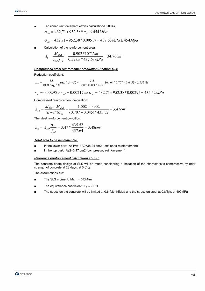
ADVANCE VALIDATION GUIDE
405
■ Tensioned reinforcement efforts calculation(S500A):
MPasusu 454*38,95271,432
MpaMPasu 45463.43700517.0*38,95271,432
■ Calculation of the reinforcement area:
²76.3463.437*593.0
10*902.0
.
61
1 cmMPam
Nm
fz
MA
ydlu
Ed
Compressed steel reinforcement reduction (Section As2):
Reduction coefficient:
9572045070704040707040401000
53α
α1000
53ε ...*.
.*.*
.)'dd*(
d**
,lu
lusc ‰
MPascydsc 52.43500295.0*38.95271.43200217.000295.0
Compressed reinforcement calculation:
²47.352.435*)045.0707.0(
902.0002.1
)'(1
2 cmdd
MMA
sc
EdEds
The steel reinforcement condition:
²48.364.437
52.435*47.3.22 cm
fAA
yd
scs
Total area to be implemented:
■ In the lower part: As1=A1+A2=38.24 cm2 (tensioned reinforcement)
■ In the top part: As2=3.47 cm2 (compressed reinforcement)
Reference reinforcement calculation at SLS:
The concrete beam design at SLS will be made considering a limitation of the characteristic compressive cylinder strength of concrete at 28 days, at 0.6*fck
The assumptions are:
■ The SLS moment: kNmMEcq 705
■ The equivalence coefficient: 9420α .e
■ The stress on the concrete will be limited at 0.6*fck=15Mpa and the stress on steel at 0.8*fyk, or 400MPa
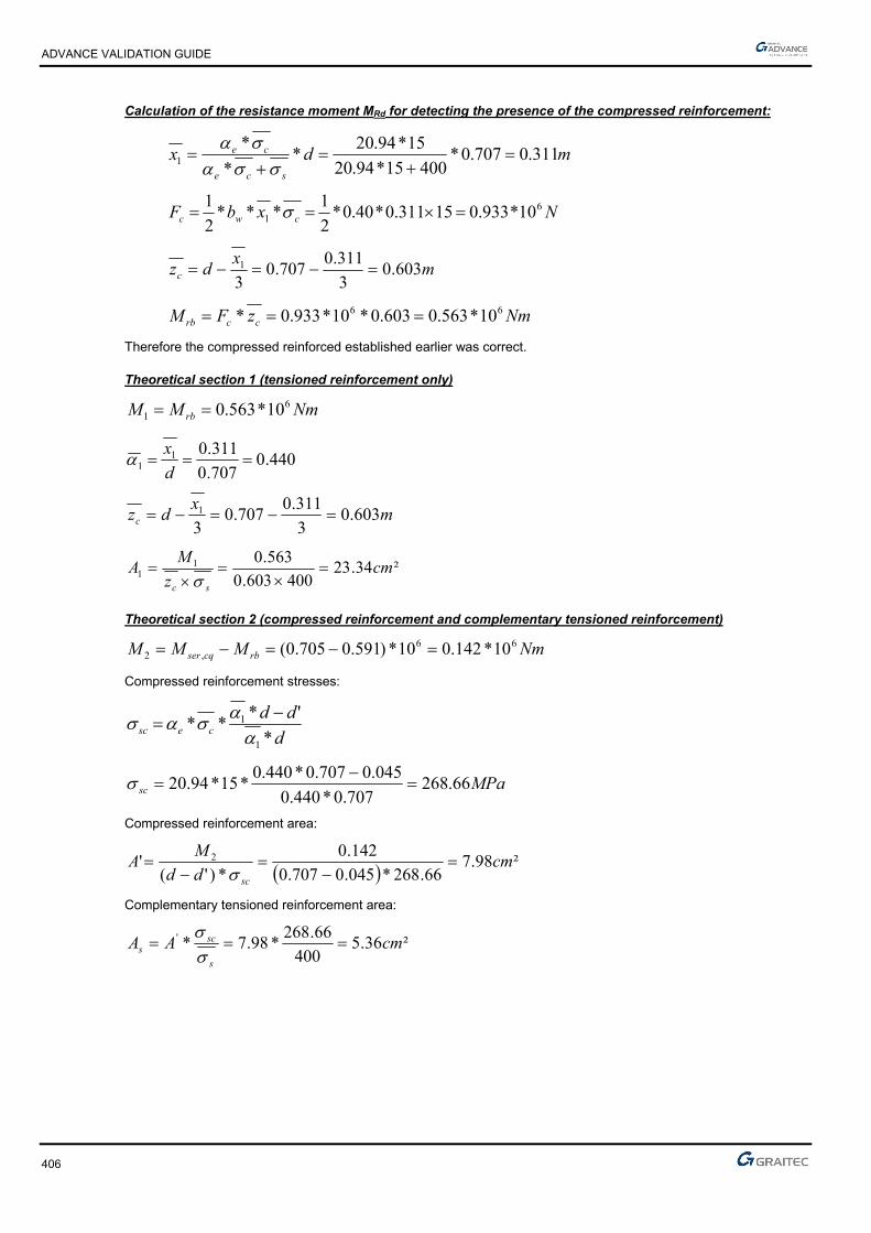
ADVANCE VALIDATION GUIDE
406
Calculation of the resistance moment MRd for detecting the presence of the compressed reinforcement:
mdxsce
ce 311.0707.0*40015*94.20
15*94.20*
*
*1
NxbF cwc6
1 10*933.015311.0*40.0*2
1***
2
1
mx
dzc 603.03
311.0707.0
31
NmzFM ccrb66 10*563.0603.0*10*933.0*
Therefore the compressed reinforced established earlier was correct.
Theoretical section 1 (tensioned reinforcement only)
NmMM rb6
1 10*563.0
440.0707.0
311.011
d
x
mx
dzc 603.03
311.0707.0
31
²34.23400603.0
563.011 cm
z
MA
sc
Theoretical section 2 (compressed reinforcement and complementary tensioned reinforcement)
NmMMM rbcqser66
,2 10*142.010*)591.0705.0(
Compressed reinforcement stresses:
d
ddcesc *
'***
1
1
MPasc 66.268707.0*440.0
045.0707.0*440.0*15*94.20
Compressed reinforcement area:
²98.766.268*045.0707.0
142.0
*)'(' 2 cm
dd
MA
sc
Complementary tensioned reinforcement area:
²36.5400
66.268*98.7*' cmAA
s
scs

ADVANCE VALIDATION GUIDE
407
Section area:
Tensioned reinforcement: 23.34+5.36=28.7 cm2
Compressed reinforcement: 7.98 cm2
Considering an envelope calculation of ULS and SLS, it will be obtained:
Tensioned reinforcement ULS: A=38.24cm2
Compressed reinforcement SLS: A=7.98cm2
To optimize the reinforcement area, it is preferable a third iteration by recalculating with SLS as a baseline amount of tensioned reinforcement (after ULS: Au=38.24cm2)
Reference reinforcement third calculation at SLS:
For this third iteration, the calculation will begin considering the section of the tensile reinforcement found when calculating for ULS: Au=38.24cm2
From this value, it will be calculated the stress obtained in the tensioned reinforcement:
MPaA
As
ELU
ELSs 21.300400*
24.38
70.28*
Calculating the moment resistance Mrb for detecting the presence of compressed steel reinforcement:
mdxsce
ce 361.0707.0*21.30015*94.20
15*94.20*
*
*1
NxbF cwc6
1 10*083.115361.0*40.0*2
1***
2
1
mx
dzc 587.03
361.0707.0
31
NmzFM ccrb66 10*636.0587.0*10*083.1*
Therefore the compressed reinforced established earlier was correct.
Theoretical section 1 (tensioned reinforcement only)
NmMM rb6
1 10*636.0
511.0707.0
361.011
d
x
mx
dzc 587.03
361.0707.0
31
²09.36400*578.0
36.0
*1
1 cmz
MA
sc
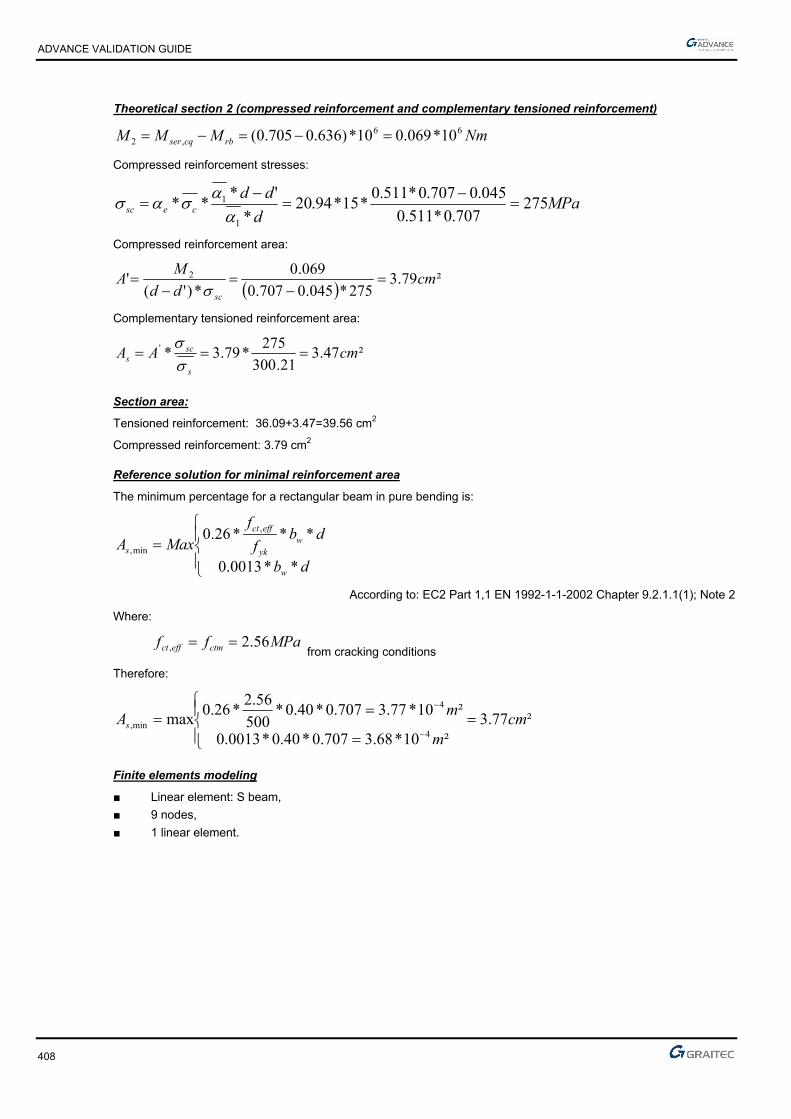
ADVANCE VALIDATION GUIDE
408
Theoretical section 2 (compressed reinforcement and complementary tensioned reinforcement)
NmMMM rbcqser66
,2 10*069.010*)636.0705.0(
Compressed reinforcement stresses:
MPad
ddcesc 275
707.0*511.0
045.0707.0*511.0*15*94.20
*
'***
1
1
Compressed reinforcement area:
²79.3275*045.0707.0
069.0
*)'(' 2 cm
dd
MA
sc
Complementary tensioned reinforcement area:
²47.321.300
275*79.3*' cmAA
s
scs
Section area:
Tensioned reinforcement: 36.09+3.47=39.56 cm2
Compressed reinforcement: 3.79 cm2
Reference solution for minimal reinforcement area
The minimum percentage for a rectangular beam in pure bending is:
db
dbf
f
MaxA
w
wyk
effct
s
**0013.0
***26.0 ,
min,
According to: EC2 Part 1,1 EN 1992-1-1-2002 Chapter 9.2.1.1(1); Note 2
Where:
MPaff ctmeffct 56.2, from cracking conditions
Therefore:
²77.3²10*68.3707.0*40.0*0013.0
²10*77.3707.0*40.0*500
56.2*26.0
max4
4
min, cmm
mAs
Finite elements modeling
■ Linear element: S beam,
■ 9 nodes,
■ 1 linear element.
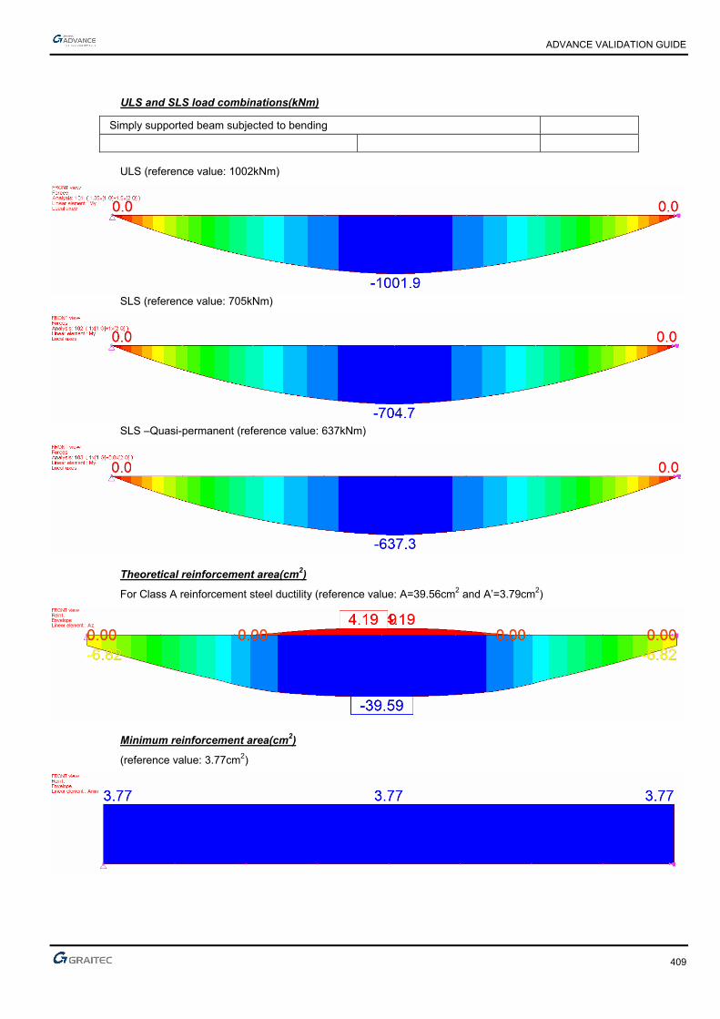
ADVANCE VALIDATION GUIDE
409
ULS and SLS load combinations(kNm)
Simply supported beam subjected to bending
ULS (reference value: 1002kNm)
SLS (reference value: 705kNm)
SLS –Quasi-permanent (reference value: 637kNm)
Theoretical reinforcement area(cm2)
For Class A reinforcement steel ductility (reference value: A=39.56cm2 and A’=3.79cm2)
Minimum reinforcement area(cm2)
(reference value: 3.77cm2)

ADVANCE VALIDATION GUIDE
410
5.14.2.4 Reference results
Result name Result description Reference value
My,ULS My corresponding to the 101 combination (ULS) [kNm] 1001 kNm
My,SLS,cq My corresponding to the 102 combination (SLS) [kNm] 705 kNm
My,SLS,qp My corresponding to the 102 combination (SLS) [kNm] 637 cm2
Az (Class A) Theoretical reinforcement area [cm2] 39.56 cm2
Amin Minimum reinforcement area [cm2] 3.77 cm2
5.14.3 Calculated results
Result name Result description Value Error
My My USL -1001.92 kN*m -0.0001 %
My My SLS cq -704.714 kN*m 0.0000 %
My My SLS qp -637.304 kN*m 0.0001 %
Az Az -39.5904 cm² -0.0001 %
Amin Amin 3.77193 cm² 0.0001 %

ADVANCE VALIDATION GUIDE
411
5.15 EC2 Test 3: Verifying a rectangular concrete beam subjected to uniformly distributed load, with compressed reinforcement- Bilinear stress-strain diagram
Test ID: 4976
Test status: Passed
5.15.1 Description
Verifies the adequacy of a rectangular cross section made from concrete C25/30 to resist simple bending. During this test, the determination of stresses is made along with the determination of the longitudinal reinforcement and the verification of the minimum reinforcement percentage.
The objective is to verify:
- The stresses results
- The longitudinal reinforcement
- The verification of the minimum reinforcement percentage
5.15.2 Background
Simple Bending Design for Ultimate Limit State
Verifies the adequacy of a rectangular cross section made from concrete C25/30 to resist simple bending. During this test, the calculation of stresses is made along with the calculation of the longitudinal reinforcement and the verification of the minimum reinforcement percentage.
5.15.2.1 Model description
■ Reference: Guide de validation Eurocode 2 EN 1992-1-1-2002;
■ Analysis type: static linear (plane problem);
■ Element type: linear.
The following load cases and load combinations are used:
■ Loadings from the structure: G = 70 kN/m,
■ Exploitation loadings (category A): Q = 80kN/m,
■ ■ The ultimate limit state (ULS) combination is: Cmax = 1.35 x G + 1.5 x Q
■ Characteristic combination of actions: CCQ = 1.0 x G + 1.0 x Q
■ Quasi-permanent combination of actions: CQP = 1.0 x G + 0.3 x Q
The objective is to verify:
■ The stresses results
■ The longitudinal reinforcement
■ The verification of the minimum reinforcement percentage
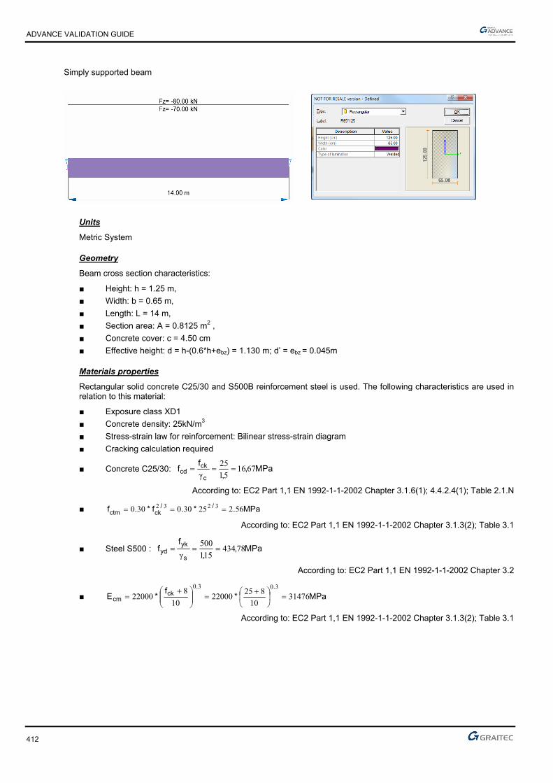
ADVANCE VALIDATION GUIDE
412
Simply supported beam
Units
Metric System
Geometry
Beam cross section characteristics:
■ Height: h = 1.25 m,
■ Width: b = 0.65 m,
■ Length: L = 14 m,
■ Section area: A = 0.8125 m2 ,
■ Concrete cover: c = 4.50 cm
■ Effective height: d = h-(0.6*h+ebz) = 1.130 m; d’ = ebz = 0.045m
Materials properties
Rectangular solid concrete C25/30 and S500B reinforcement steel is used. The following characteristics are used in relation to this material:
■ Exposure class XD1
■ Concrete density: 25kN/m3
■ Stress-strain law for reinforcement: Bilinear stress-strain diagram
■ Cracking calculation required
■ Concrete C25/30: MPa,,
ff
c
ckcd 6716
51
25
γ
According to: EC2 Part 1,1 EN 1992-1-1-2002 Chapter 3.1.6(1); 4.4.2.4(1); Table 2.1.N
■ MPa.*.f*.f //ckctm 56225300300 3232
According to: EC2 Part 1,1 EN 1992-1-1-2002 Chapter 3.1.3(2); Table 3.1
■ Steel S500 : MPa,,
ff
s
ykyd 78434
151
500
γ
According to: EC2 Part 1,1 EN 1992-1-1-2002 Chapter 3.2
■ MPa*f
*E..
ckcm 31476
10
82522000
10
822000
3030
According to: EC2 Part 1,1 EN 1992-1-1-2002 Chapter 3.1.3(2); Table 3.1
ADVANCE VALIDATION GUIDE
413
Boundary conditions
The boundary conditions are described below:
■ Outer:
► Support at start point (x=0) restrained in translation along X, Y and Z,
► Support at end point (x = 14) restrained in translation along Z.
■ Inner: None.
Loading
The beam is subjected to the following load combinations:
■ Load combinations:
The ultimate limit state (ULS) combination is:
Cmax = 1.35 x G + 1.5 x Q=1.35*70+1.5*80=214.5*103 N/ml
Characteristic combination of actions:
CCQ = 1.0 x G + 1.0 x Q=70+80=150*103 N/ml
Quasi-permanent combination of actions:
CQP = 1.0 x G + 0.3 x Q=70+0.3*80=94*103 N/ml
■ Load calculations:
Nm*.²*.
MEd6102555
8
145214
Nm*.²*
MEcq6106753
8
14150150
Nm*.²*
MEqp6103032
8
1494
ADVANCE VALIDATION GUIDE
414
5.15.2.2 Reference results in calculating the equivalent coefficient
To determine the equivalence coefficient, we must first estimate the creep coefficient, related to elastic deformation at 28 days and 50% humidity:
■ )t(*)f(*)t,( cmRH 00 ββ
According to: EC2 Part 1,1 EN 1992-1-1-2002; Annex B; Chapter B.1(1); B.2
■ 9252825
816816β .
.
f
.)f(
cmcm
According to: EC2 Part 1,1 EN 1992-1-1-2002; Annex B; Chapter B.1(1); B.4
■ 48802810
1
10
1β
2002000
0 ..t.
)t(..
at t0=28 days
According to: EC2 Part 1,1 EN 1992-1-1-2002; Annex B; Chapter B.1(1); B.5
The value of the φRH coefficient depends of the concrete quality:
■ 213
0
αα10
1001
1 **h*.
RH
RH
According to: EC2 Part 1,1 EN 1992-1-1-2002; Annex B; Chapter B.1(1); B.3a
■ 121 if MPafcm 35
■ If not:
70
135
α.
cmf
and
20
235
α.
cmf
According to: EC2 Part 1,1 EN 1992-1-1-2002; Annex B; Chapter B.1(1); B.8c
■ In our case we have: 1338 21 MpaMpaff ckcm
■ 6616342710
100
501
16342712506502
12506502230 .
.*.mm.
)(*
**
u
Ac*h RH
According to: EC2 Part 1,1 EN 1992-1-1-2002; Annex B; Chapter B.1(1); B.6
■ 375248809252661ββ 00 ..*.*.)t(*)f(*)t,( cmRH
The coefficient of equivalence is determined by the following formula:
■
Ecar
Eqp
cm
se
M
M*)t,(
EE
01
α
Defined earlier:
NmMEcar310*3675
NmMEqp310*2303
This gives:
8215
103975
1023037021
31476200000
α
3
3
.
*
**.
e
ADVANCE VALIDATION GUIDE
415
5.15.2.3 Reference results in calculating the concrete beam reduced moment limit
For the calculation of steel ULS, we consider the moment reduced limit of 372.0lu for a steel grade 500Mpa.
Therefore, make sure to enable the option "limit )500/372.0( S " in Advance Design.
Reference reinforcement calculation at SLU:
The calculation of the reinforcement is detailed below:
■ Effective height: d=0.9*h=1.125 m
■ Calculation of reduced moment:
383,067,16*²125.1*65,0
10*25.5255
*²* 2
3
MPamm
Nm
fdb
M
cdw
Edcu
372.0383.0 lucu therefore the compressed reinforced must be resized and then the concrete section
must be adjusted.
Calculation of the tension steel section (Section A1):
The calculation of tensioned steel section must be conducted with the corresponding moment of :
NmfdbM cdwluEd6
1 10*10.567.16*²125.1*65.0*372.0*²**
■ The α value: 61803720211251μ211251α .).*(*.)*(*. lulu
■ Calculation of the lever arm zc: m.).*.(*.)*.(*dz lulu 851061804011301α401
■ Calculation of the reinforcement area:
²35.13778.434*851.0
10*10.5
.
61
1 cmMPam
Nm
fz
MA
ydlu
Ed

ADVANCE VALIDATION GUIDE
416
Compressed steel reinforcement reduction (Section As2):
Reduction coefficient:
00327.0045.0130.1*618.0130.1*618.0*1000
5.3)'*(
**1000
5,3 dd
d lulu
sc
MPaf ydscydsc 78.43400217.000327.0
Compressed reinforcement calculation:
²32.278.434)045.0130.1(
15.5255.5
)'(1
2 cmdd
MMA
sc
EdEds
The steel reinforcement condition:
²32.2.22 cmf
AAyd
scs
Total area to be implemented:
In the lower part: As1=A1+A2=142.42 cm2
In the top part: As2=2.32 cm2
Reference reinforcement calculation at SLS:
The concrete beam design at SLS will be made considering a limitation of the characteristic compressive cylinder strength of concrete at 28 days, at 0.6*fck
The assumptions are:
■ The SLS moment: Nm*.²*
MEcq6106753
8
14150150
■ The equivalence coefficient: 8215α .e
■ The stress on the concrete will be limited at 0.6*fck=15Mpa and the stress on steel at 0.8*fyk, or 400MPa
Calculation of the resistance moment MRd for detecting the presence of the compressed reinforcement:
m..*.
*.d.
*
*x
sce
ce 41901251400158215
158215
σσα
σα1
N*..*.**x*b*F cwc6
1 100421541906502
1σ
2
1
m..
.x
dzc 98503
41901251
31
Nm*..**.z*FM ccrb66 10012985010042
Therefore the compressed reinforced established earlier was correct.

ADVANCE VALIDATION GUIDE
417
Theoretical section 1 (tensioned reinforcement only)
NmMM rb6
1 10*01.2
372.0125.1
419.011
d
x
mx
dzc 985.03
419.0125.1
31
²01.51400985.0
01.211 cm
z
MA
sc
Theoretical section 2 (compressed reinforcement and complementary tensioned reinforcement)
NmMMM rbcqser66
,2 10*665.110*)01.2675.3(
Compressed reinforcement stresses:
d
ddcesc *
'***
1
1
MPasc 78.211125.1*372.0
045.0125.1*372.0*15*82.15
Compressed reinforcement area:
²92.7178.211*045.0125.1
645.1
*)'(' 2 cm
dd
MA
sc
Complementary tensioned reinforcement area:
²08.38400
78.211*92.71*' cmAA
s
scs
Section area:
Tensioned reinforcement: 51.01+38.08=89.09 cm2
Compressed reinforcement: 71.92 cm2
Considering an envelope calculation of ULS and SLS, it will be obtained:
Tensioned reinforcement ULS: A=141.42cm2
Compressed reinforcement SLS: A=71.92cm2
To optimize the reinforcement area, it is preferable a third iteration by recalculating with SLS as a baseline amount of tensioned reinforcement (after ULS: Au=141.44cm2)

ADVANCE VALIDATION GUIDE
418
Reference reinforcement additional iteration for calculation at SLS:
For this iteration the calculation will be started from the section of the tensioned reinforcement found when calculating the SLS: Au=141.44cm2.
For this particular value, it will be calculated the resistance obtained for tensioned reinforcement:
MPaA
As
ELU
ELSs 252400
42.141
18.89
This is a SLS calculation, considering this limitation:
Calculating the moment resistance MRb for detecting the presence of compressed steel reinforcement:
mdxsce
ce 55.0130.1*25215*82.15
15*82.15*
*
*1
NxbF cwc6
1 10*67.215*55.0*65.0*2
1***
2
1
mx
dzc 94.03
55.0125.1
31
Nmx
dxbzFM cwccrb61
1 10*52.23
55.0125.1*15*55.0*65.0*
2
1
3****
2
1*
According to the calculation above Mser,cq is grater then Mrb the compressed steel reinforcement is set.
Theoretical section 1 (tensioned reinforcement only)
NmMM rb6
1 10*52.2
488.0125.1
55.011 d
x
mx
dzc 94.03
548.0125.1
31
²38.10625294.0
52.211 cmz
MA
sc
Theoretical section 2 (compressed reinforcement and complementary tensioned reinforcement)
NmMMM rbcqser66
,2 10*155.110*)52.2675.3(
Compressed reinforcement stresses:
d
ddcesc *
'***
1
1
MPasc 73.217125.1*485.0
045.0125.1*485.0*15*82.15
ADVANCE VALIDATION GUIDE
419
Compressed reinforcement area:
²12.4973.217*045.0125.1
155.1
*)'(' 2 cm
dd
MA
sc
Complementary tensioned reinforcement area:
²44.42252
73.217*12.49*' cmAA
s
scs
Section area:
Tensioned reinforcement: 106.38+42.44=148.82 cm2
Compressed reinforcement: 49.12 cm2
Reference solution for minimal reinforcement area
The minimum percentage for a rectangular beam in pure bending is:
db
dbf
f
MaxA
w
wyk
effct
s
**0013.0
***26.0 ,
min,
According to: EC2 Part 1,1 EN 1992-1-1-2002 Chapter 9.2.1.1(1); Note 2
Where:
MPaff ctmeffct 56.2, from cracking conditions
Therefore:
²73.9²10*51.9125.1*65.0*0013.0
²10*73.9125.1*65.0*500
56.2*26.0
max4
4
min, cmm
mAs
Finite elements modeling
■ Linear element: S beam,
■ 15 nodes,
■ 1 linear element.

ADVANCE VALIDATION GUIDE
420
ULS and SLS load combinations(kNm)
Simply supported beam subjected to bending
ULS (reference value: 5255kNm)
SLS –Characteristic (reference value: 3675kNm)
SLS –Quasi-permanent (reference value: 2303kNm)
Theoretical reinforcement area(cm2)
(reference value: A’=148.82cm2 A=49.12cm2)
Minimum reinforcement area(cm2)
(reference value: 9.73cm2)

ADVANCE VALIDATION GUIDE
421
5.15.2.4 Reference results
Result name Result description Reference value
My,ULS My corresponding to the 101 combination (ULS) [kNm] 5255 kNm
My,SLS,c My corresponding to the 102 combination (SLS) [kNm] 3675 kNm
My,SLS,q My corresponding to the 103 combination (SLS) [kNm] 2303 kNm
Az (A’) Tensioned theoretical reinforcement area [cm2] 148.82 cm2
Amin Minimum reinforcement area [cm2] 9.73 cm2
5.15.3 Calculated results
Result name Result description Value Error
My My USL -5255.25 kN*m 0.0000 %
My My SLS cq -3675 kN*m 0.0000 %
My My SLS pq -2303 kN*m 0.0000 %
Az Az -147.617 cm² -0.0003 %
Amin Amin 9.79662 cm² 0.0000 %
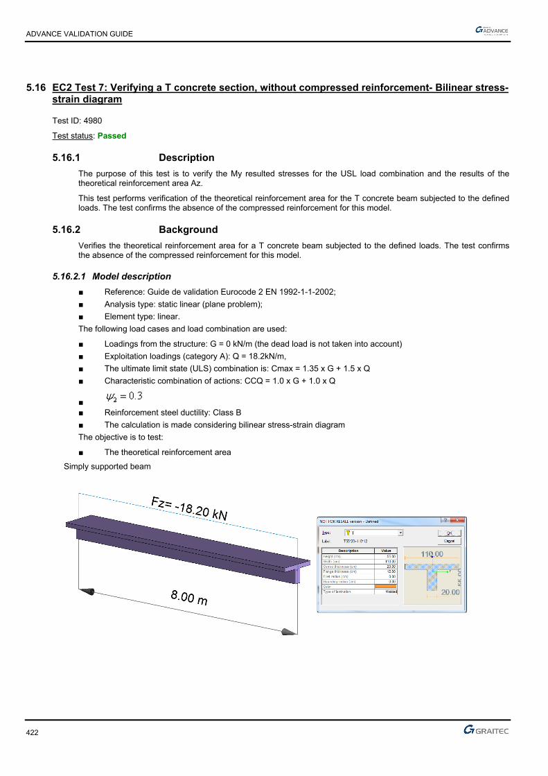
ADVANCE VALIDATION GUIDE
422
5.16 EC2 Test 7: Verifying a T concrete section, without compressed reinforcement- Bilinear stress-strain diagram
Test ID: 4980
Test status: Passed
5.16.1 Description
The purpose of this test is to verify the My resulted stresses for the USL load combination and the results of the theoretical reinforcement area Az.
This test performs verification of the theoretical reinforcement area for the T concrete beam subjected to the defined loads. The test confirms the absence of the compressed reinforcement for this model.
5.16.2 Background
Verifies the theoretical reinforcement area for a T concrete beam subjected to the defined loads. The test confirms the absence of the compressed reinforcement for this model.
5.16.2.1 Model description
■ Reference: Guide de validation Eurocode 2 EN 1992-1-1-2002;
■ Analysis type: static linear (plane problem);
■ Element type: linear.
The following load cases and load combination are used:
■ Loadings from the structure: G = 0 kN/m (the dead load is not taken into account)
■ Exploitation loadings (category A): Q = 18.2kN/m,
■ The ultimate limit state (ULS) combination is: Cmax = 1.35 x G + 1.5 x Q
■ Characteristic combination of actions: CCQ = 1.0 x G + 1.0 x Q
■ ■ Reinforcement steel ductility: Class B
■ The calculation is made considering bilinear stress-strain diagram
The objective is to test:
■ The theoretical reinforcement area
Simply supported beam

ADVANCE VALIDATION GUIDE
423
Units
Metric System
Geometry
Beam cross section characteristics:
■ Beam length: 8m
■ Concrete cover: c=3.50 cm
■ Effective height: d=h-(0.6*h+ebz)=0.482 m; d’=ebz=0.035m
Materials properties
Rectangular solid concrete C25/30 and S400B reinforcement steel is used. The following characteristics are used in relation to this material:
■ Exposure class XC1
■ Concrete density: 25kN/m3
■ Reinforcement steel ductility: Class B
■ The calculation is made considering bilinear stress-strain diagram
■ Concrete C25/30: MPaf
fc
ckcd 67.10
5,1
25
According to: EC2 Part 1,1 EN 1992-1-1-2002 Chapter 3.1.6(1); 4.4.2.4(1); Table 2.1.N
■ MPaff ckctm 56.225*30.0*30.0 3/23/2
According to: EC2 Part 1,1 EN 1992-1-1-2002 Chapter 3.1.3(2); Table 3.1
■ Steel S400B : MPaf
fs
ykyd 83.347
15,1
400
According to: EC2 Part 1,1 EN 1992-1-1-2002 Chapter 3.2
Boundary conditions
The boundary conditions are described below:
■ Outer:
► Support at start point (x = 0) restrained in translation along X, Y and Z,
► Support at end point (x = 8) restrained in translation along Y and Z, and restrained rotation along X.
■ Inner: None.

ADVANCE VALIDATION GUIDE
424
Loading
The beam is subjected to the following load combinations:
■ Load combinations:
The ultimate limit state (ULS) combination is:
Cmax = 1.35 x G + 1.5 x Q=1.35*0+1.5*18.2=27.3kN/ml
Characteristic combination of actions:
CCQ = 1.0 x G + 1.0 x Q=0+18.2=18.2kN/ml
■ Load calculations:
kNmMEd 40.2188
²8*3.27
kNmMEcq 60.1458
²8*20.18
5.16.2.2 Reference results in calculating the concrete beam moment
At first it will be determined the moment resistance of the concrete section only:
kNmfh
dhbM cdf
feffbtu 92867.16*2
12.0482.0*12.0*10.1*
2**
Comparing Mbtu with MEd:
Therefore, the concrete section is not entirely compressed; This requires a calculation considering a rectangular section of b=110cm and d=48.2cm.
Reference longitudinal reinforcement calculation:
051.067.16*²482.0*10.1
218.0
*²*1
cdw
Edcu Fdb
M
066.0051.0*211*25.1)*21(1*25.1 cuu
mdz uc 469.0)066.0*40.01(*482.0)*4.01(*
²38.1383.347*469.0
218.0
*cm
fz
MA
ydc
Ed
Finite elements modeling
■ Linear element: S beam,
■ 9 nodes,
■ 1 linear element.
kNmMkNmM btuEd 92840.218

ADVANCE VALIDATION GUIDE
425
ULS load combinations(kNm)
Simply supported beam subjected to bending
Theoretical reinforcement area(cm2)
For Class B reinforcement steel ductility (reference value: A=13.38cm2)
5.16.2.3 Reference results
Result name Result description Reference value
Az (Class B) Theoretical reinforcement area [cm2] 13.38 cm2
5.16.3 Calculated results
Result name Result description Value Error
Az Az -13.3793 cm² 0.0002 %
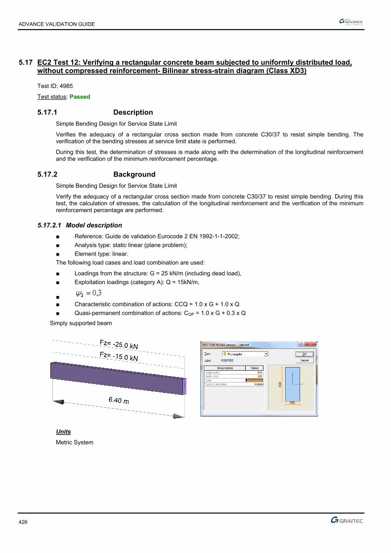
ADVANCE VALIDATION GUIDE
426
5.17 EC2 Test 12: Verifying a rectangular concrete beam subjected to uniformly distributed load, without compressed reinforcement- Bilinear stress-strain diagram (Class XD3)
Test ID: 4985
Test status: Passed
5.17.1 Description
Simple Bending Design for Service State Limit
Verifies the adequacy of a rectangular cross section made from concrete C30/37 to resist simple bending. The verification of the bending stresses at service limit state is performed.
During this test, the determination of stresses is made along with the determination of the longitudinal reinforcement and the verification of the minimum reinforcement percentage.
5.17.2 Background
Simple Bending Design for Service State Limit
Verify the adequacy of a rectangular cross section made from concrete C30/37 to resist simple bending. During this test, the calculation of stresses, the calculation of the longitudinal reinforcement and the verification of the minimum reinforcement percentage are performed.
5.17.2.1 Model description
■ Reference: Guide de validation Eurocode 2 EN 1992-1-1-2002;
■ Analysis type: static linear (plane problem);
■ Element type: linear.
The following load cases and load combination are used:
■ Loadings from the structure: G = 25 kN/m (including dead load),
■ Exploitation loadings (category A): Q = 15kN/m,
■ ■ Characteristic combination of actions: CCQ = 1.0 x G + 1.0 x Q
■ Quasi-permanent combination of actions: CQP = 1.0 x G + 0.3 x Q
Simply supported beam
Units
Metric System
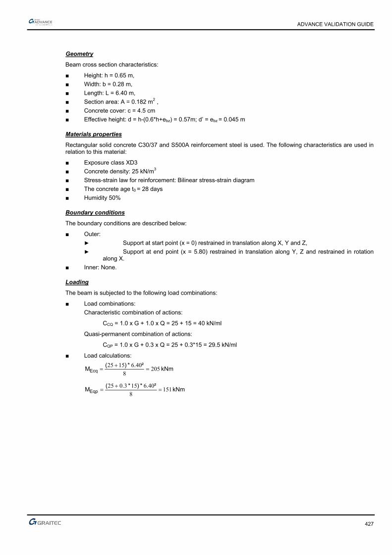
ADVANCE VALIDATION GUIDE
427
Geometry
Beam cross section characteristics:
■ Height: h = 0.65 m,
■ Width: b = 0.28 m,
■ Length: L = 6.40 m,
■ Section area: A = 0.182 m2 ,
■ Concrete cover: c = 4.5 cm
■ Effective height: d = h-(0.6*h+ebz) = 0.57m; d’ = ebz = 0.045 m
Materials properties
Rectangular solid concrete C30/37 and S500A reinforcement steel is used. The following characteristics are used in relation to this material:
■ Exposure class XD3
■ Concrete density: 25 kN/m3
■ Stress-strain law for reinforcement: Bilinear stress-strain diagram
■ The concrete age t0 = 28 days
■ Humidity 50%
Boundary conditions
The boundary conditions are described below:
■ Outer:
► Support at start point (x = 0) restrained in translation along X, Y and Z,
► Support at end point (x = 5.80) restrained in translation along Y, Z and restrained in rotation along X.
■ Inner: None.
Loading
The beam is subjected to the following load combinations:
■ Load combinations:
Characteristic combination of actions:
CCQ = 1.0 x G + 1.0 x Q = 25 + 15 = 40 kN/ml
Quasi-permanent combination of actions:
CQP = 1.0 x G + 0.3 x Q = 25 + 0.3*15 = 29.5 kN/ml
■ Load calculations:
kNm².*)(
MEcq 2058
4061525
kNm².*)*.(
MEqp 1518
406153025

ADVANCE VALIDATION GUIDE
428
5.17.2.2 Reference results in calculating the concrete final value of creep coefficient
)()(),( 00 tft cmRH
Where:
MPaf
fcm
cm 725.2830
8.168.16)(
488.0281.0
1
1.0
1)(
20.020.00
0
t
t
t0 : concrete age t0=28days
21
03
***1.0100
11
h
RH
RH
121 if Mpafcm 35
If not 70
135
α.
cmf
and
20
235
α.
cmf
In this case therefore
944.038
35357.07.0
1
cmf
984.038
35352.02.0
2
cmf
In this case:
Humidity RH = 50 %
mmu
Ach 70.195
650280*2
650*280*220
37.2488.0*73.2*78.1)(*)(*),(78.1984.0*70.195*1.0
100
501
1 003
tft cmRHRH

ADVANCE VALIDATION GUIDE
429
Calculating the equivalence coefficient:
The coefficient of equivalence is determined by the following formula:
Ecar
Eqp
cm
se
M
Mt
EE
*),(1 0
Where:
MPaf
E ckcm 32837
10
830*22
10
8*22
3.03.0
MPaEs 200000
75.2205
151*37.21*),(1 0
Ecar
Eqp
M
Mt
76.16
205
151*37.21
32837200000
*),(1 0
Ecar
Eqp
cm
se
M
Mt
EE
Material characteristics:
The maximum compression on the concrete is: Mpafckbc 1830*6,0*6,0
For the maximum stress on the steel taut, we consider the constraint limit Mpaf yks 400*8,0
Neutral axis position calculation:
The position of the neutral axis must be determined by calculating 1 (position corresponding to the state of
maximum stress on the concrete and reinforcement):
430.040018*76.16
15*76.16
*
*1
sce
ce
Moment resistance calculation:
Knowing the 1α value, it can be determined the moment resistance of the concrete section, using the following
formulas:
243057004300α11 ..*.d*x m
MNm..
.**.*.*.x
d**x*b*M cwrb 29703
2430570018243028050
3σ
2
1 11
Where:
Utile height : d = h – (0.06h + ebz) = 0.57 m
The moment resistance Mrb = 297 KNm
Because kNmMkNmM rbEcq 297205 the supposition of having no compressed reinforcement is correct.

ADVANCE VALIDATION GUIDE
430
Calculation of reinforcement area with max constraint on steel and concrete
The reinforcement area is calculated using the SLS load combination
Neutral axis position: 4300α1 ,
Lever arm: m..
*.*dzc 48503
43001570
3
α1 1
Reinforcement section: ²cm.*.
.
*z
MA
sc
serser,s 5610
4004850
2050
σ1
Reference solution for minimal reinforcement area
The minimum percentage for a rectangular beam in pure bending is:
d*b*.
d*b*f
f*.
MaxA
w
wyk
eff,ct
min,s
00130
260
According to: EC2 Part 1,1 EN 1992-1-1-2002 Chapter 9.2.1.1(1); Note 2
Where:
MPa.ff ctmeff,ct 8962 from cracking conditions
Therefore:
²cm.
²m*..*.*.
²m*..*.*.
.maxA min,s 402
1007257028000130
10402570280500
8962260
4
4
Finite elements modeling
■ Linear element: S beam,
■ 7 nodes,
■ 1 linear element.

ADVANCE VALIDATION GUIDE
431
ULS and SLS load combinations (kNm)
Simply supported beam subjected to bending
SLS (reference value: 205kNm)
Theoretical reinforcement area (cm2)
(reference value: 10.50cm2)
Minimum reinforcement area (cm2)
(reference value: 2.40cm2)
5.17.2.3 Reference results
Result name Result description Reference value
My,SLS My corresponding to the 102 combination (SLS) [kNm] 205 kNm
Az Theoretical reinforcement area [cm2] 10.50 cm2
Amin Minimum reinforcement area [cm2] 2.39 cm2
5.17.3 Calculated results
Result name Result description Value Error
My My SLS -204.8 kN*m 0.0000 %
Az Az -10.3489 cm² -0.0001 %
Amin Amin -2.38697 cm² 0.0001 %
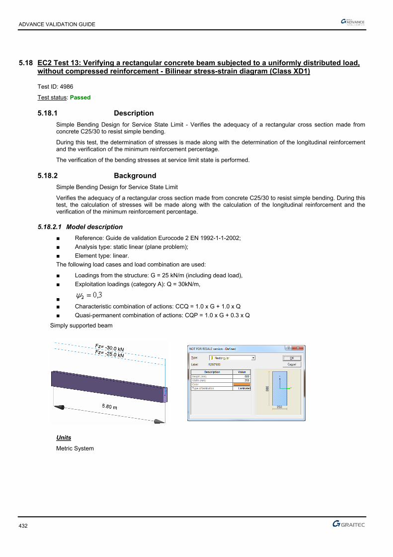
ADVANCE VALIDATION GUIDE
432
5.18 EC2 Test 13: Verifying a rectangular concrete beam subjected to a uniformly distributed load, without compressed reinforcement - Bilinear stress-strain diagram (Class XD1)
Test ID: 4986
Test status: Passed
5.18.1 Description
Simple Bending Design for Service State Limit - Verifies the adequacy of a rectangular cross section made from concrete C25/30 to resist simple bending.
During this test, the determination of stresses is made along with the determination of the longitudinal reinforcement and the verification of the minimum reinforcement percentage.
The verification of the bending stresses at service limit state is performed.
5.18.2 Background
Simple Bending Design for Service State Limit
Verifies the adequacy of a rectangular cross section made from concrete C25/30 to resist simple bending. During this test, the calculation of stresses will be made along with the calculation of the longitudinal reinforcement and the verification of the minimum reinforcement percentage.
5.18.2.1 Model description
■ Reference: Guide de validation Eurocode 2 EN 1992-1-1-2002;
■ Analysis type: static linear (plane problem);
■ Element type: linear.
The following load cases and load combination are used:
■ Loadings from the structure: G = 25 kN/m (including dead load),
■ Exploitation loadings (category A): Q = 30kN/m,
■ ■ Characteristic combination of actions: CCQ = 1.0 x G + 1.0 x Q
■ Quasi-permanent combination of actions: CQP = 1.0 x G + 0.3 x Q
Simply supported beam
Units
Metric System

ADVANCE VALIDATION GUIDE
433
Geometry
Below are described the beam cross section characteristics:
■ Height: h = 0.60 m,
■ Width: b = 0.25 m,
■ Length: L = 5.80 m,
■ Section area: A = 0.150 m2 ,
■ Concrete cover: c=4.5cm
■ Effective height: d=h-(0.6*h+ebz)=0.519m; d’=ebz=0.045m
Materials properties
Rectangular solid concrete C25/30 and S500A reinforcement steel is used. The following characteristics are used in relation to this material:
■ Exposure class XD1
■ Concrete density: 25kN/m3
■ Stress-strain law for reinforcement: Bilinear stress-strain diagram
■ The concrete age t0=28 days
■ Humidity RH=50%
Boundary conditions
The boundary conditions are described below:
■ Outer:
► Support at start point (x = 0) restrained in translation along X, Y and Z,
► Support at end point (x = 5.80) restrained in translation along Y, Z and restrained in rotation along X.
■ Inner: None.
Loading
The beam is subjected to the following load combinations:
■ Load combinations:
Characteristic combination of actions:
CCQ = 1.0 x G + 1.0 x Q = 25 + 30 = 55 kN/ml
Quasi-permanent combination of actions:
CQP = 1.0 x G + 0.3 x Q = 25 + 0.3*30 = 34 kN/ml
■ Load calculations:
kNmMEcq 28.2318
²80.5*)3025(
kNmMEqp 97.1428
²80.5*)30*3.025(

ADVANCE VALIDATION GUIDE
434
5.18.2.2 Reference results in calculating the concrete final value of creep coefficient
)()(),( 00 tft cmRH
Where:
MPaf
fcm
cm 92.2825
8.168.16)(
488.0281.0
1
1.0
1)(
20.020.00
0
t
t
t0 : concrete age t0 = 28 days
21
03
***1.0100
11
h
RH
RH
121 if Mpafcm 35
If not
7.0
1
35
cmf
and
2.0
2
35
cmf
In this case, therefore:
121
In this case:
Humidity RH = 50 %
mmu
Ach 176
600250*2
600*250*220
70.2488.0*92.2*89.1)(*)(*),(89.1176*1.0
100
501
1 003
tft cmRHRH
Calculating the equivalence coefficient:
The coefficient of equivalence is determined by the following formula:
Ecar
Eqp
cm
se
M
Mt
EE
*),(1 0
Where:
MPaf
E ckcm 31476
10
825*22
10
8*22
3.03.0
MPaEs 200000
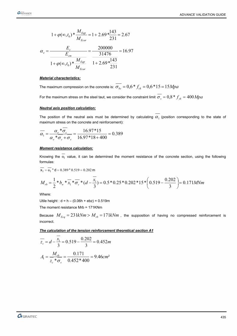
ADVANCE VALIDATION GUIDE
435
67.2231
143*69.21*),(1 0
Ecar
Eqp
M
Mt
97.16
231
143*69.21
31476200000
*),(1 0
Ecar
Eqp
cm
se
M
Mt
EE
Material characteristics:
The maximum compression on the concrete is: Mpafckbc 1515*6,0*6,0
For the maximum stress on the steel taut, we consider the constraint limit Mpaf yks 400*8,0
Neutral axis position calculation:
The position of the neutral axis must be determined by calculating 1 (position corresponding to the state of
maximum stress on the concrete and reinforcement):
389.040018*97.16
15*97.16
*
*1
sce
ce
Moment resistance calculation:
Knowing the 1α value, it can be determined the moment resistance of the concrete section, using the following
formulas:
202051903890α11 ..*.d*x m
MNmx
dxbM cwrb 171.03
202.0519.0*15*202.0*25.0*5.0)
3(****
2
1 11
Where:
Utile height : d = h – (0.06h + ebz) = 0.519m
The moment resistance Mrb = 171KNm
Because kNmMkNmM rbEcq 171231 , the supposition of having no compressed reinforcement is
incorrect.
The calculation of the tension reinforcement theoretical section A1
mx
dzc 452.03
202.0519.0
31
²46.9400*452.0
171.0
*1 cmz
MA
sc
rb
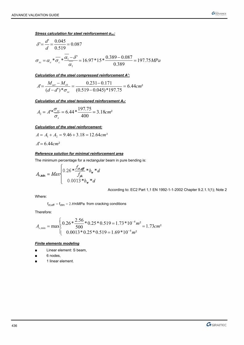
ADVANCE VALIDATION GUIDE
436
Stress calculation for steel reinforcement σsc:
087.0
519.0
045.0'' d
d
MPacesc 75.197389.0
087.0389.0*15*97.16
'**
1
1
Calculation of the steel compressed reinforcement A’:
²44.675.197*)045.0519.0(
171.0231.0
*)'(' cm
dd
MMA
sc
rbser
Calculation of the steel tensioned reinforcement A2:
²18.3400
75.197*44.6'*2 cmAA
s
sc
Calculation of the steel reinforcement:
²64.1218.346.921 cmAAA
²44.6' cmA
Reference solution for minimal reinforcement area
The minimum percentage for a rectangular beam in pure bending is:
According to: EC2 Part 1,1 EN 1992-1-1-2002 Chapter 9.2.1.1(1); Note 2
Where:
MPa.ff ctmeff,ct 8962 from cracking conditions
Therefore:
²73.1²10*69.1519.0*25.0*0013.0
²10*73.1519.0*25.0*500
56.2*26.0
max4
4
min, cmm
mAs
Finite elements modeling
■ Linear element: S beam,
■ 6 nodes,
■ 1 linear element.
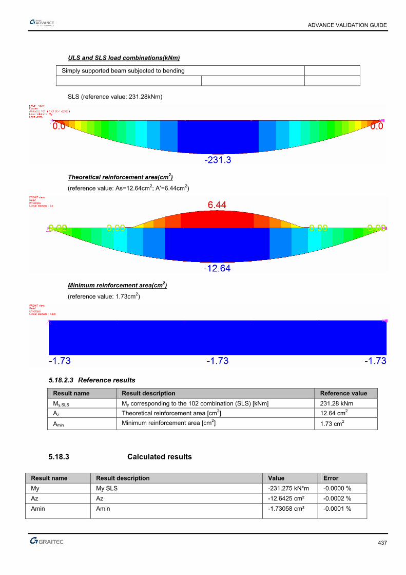
ADVANCE VALIDATION GUIDE
437
ULS and SLS load combinations(kNm)
Simply supported beam subjected to bending
SLS (reference value: 231.28kNm)
Theoretical reinforcement area(cm2)
(reference value: As=12.64cm2; A’=6.44cm2)
Minimum reinforcement area(cm2)
(reference value: 1.73cm2)
5.18.2.3 Reference results
Result name Result description Reference value
My,SLS My corresponding to the 102 combination (SLS) [kNm] 231.28 kNm
Az Theoretical reinforcement area [cm2] 12.64 cm2
Amin Minimum reinforcement area [cm2] 1.73 cm2
5.18.3 Calculated results
Result name Result description Value Error
My My SLS -231.275 kN*m -0.0000 %
Az Az -12.6425 cm² -0.0002 %
Amin Amin -1.73058 cm² -0.0001 %

ADVANCE VALIDATION GUIDE
438
5.19 EC2 Test 16: Verifying a T concrete section, without compressed reinforcement- Bilinear stress-strain diagram
Test ID: 4999
Test status: Passed
5.19.1 Description
Simple Bending Design for Service State Limit
The purpose of this test is to verify the My resulted stresses for the SLS load combination and the results of the theoretical reinforcement area Az and of the minimum reinforcement percentage. This test performs verification for the theoretical reinforcement area for the T concrete beam subjected to the defined loads. The test confirms the absence of the compressed reinforcement for this model.
5.19.2 Background
This test performs the verification of the theoretical reinforcement area for the T concrete beam subjected to the defined loads. The test confirms the absence of the compressed reinforcement for this model.
5.19.2.1 Model description
■ Reference: Guide de validation Eurocode 2 EN 1992-1-1-2002;
■ Analysis type: static linear (plane problem);
■ Element type: linear.
The following load cases and load combination are used:
■ Loadings from the structure: G = 40 kN/m (including the dead load)
■ Exploitation loadings (category A): Q = 10kN/m,
■ Characteristic combination of actions: CCQ = 1.0 x G + 1.0 x Q
■ Quasi-permanent combination of actions: CQP = 1.0 x G + 0.3 x Q
■ Reinforcement steel ductility: Class A
■ The calculation is performed considering bilinear stress-strain diagram
The objective is to verify:
■ The stresses results
■ The theoretical reinforcement area
■ The minimum reinforcement percentage
Simply supported beam
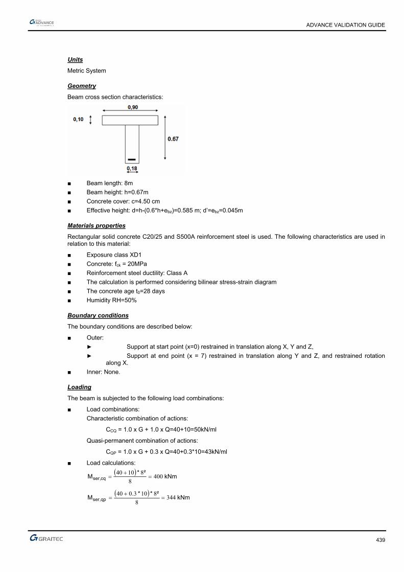
ADVANCE VALIDATION GUIDE
439
Units
Metric System
Geometry
Beam cross section characteristics:
■ Beam length: 8m
■ Beam height: h=0.67m
■ Concrete cover: c=4.50 cm
■ Effective height: d=h-(0.6*h+ebz)=0.585 m; d’=ebz=0.045m
Materials properties
Rectangular solid concrete C20/25 and S500A reinforcement steel is used. The following characteristics are used in relation to this material:
■ Exposure class XD1
■ Concrete: fck = 20MPa
■ Reinforcement steel ductility: Class A
■ The calculation is performed considering bilinear stress-strain diagram
■ The concrete age t0=28 days
■ Humidity RH=50%
Boundary conditions
The boundary conditions are described below:
■ Outer:
► Support at start point (x=0) restrained in translation along X, Y and Z,
► Support at end point (x = 7) restrained in translation along Y and Z, and restrained rotation along X.
■ Inner: None.
Loading
The beam is subjected to the following load combinations:
■ Load combinations:
Characteristic combination of actions:
CCQ = 1.0 x G + 1.0 x Q=40+10=50kN/ml
Quasi-permanent combination of actions:
CQP = 1.0 x G + 0.3 x Q=40+0.3*10=43kN/ml
■ Load calculations:
kNm
²*M cq,ser 400
8
81040
kNm
²**.M qp,ser 344
8
8103040
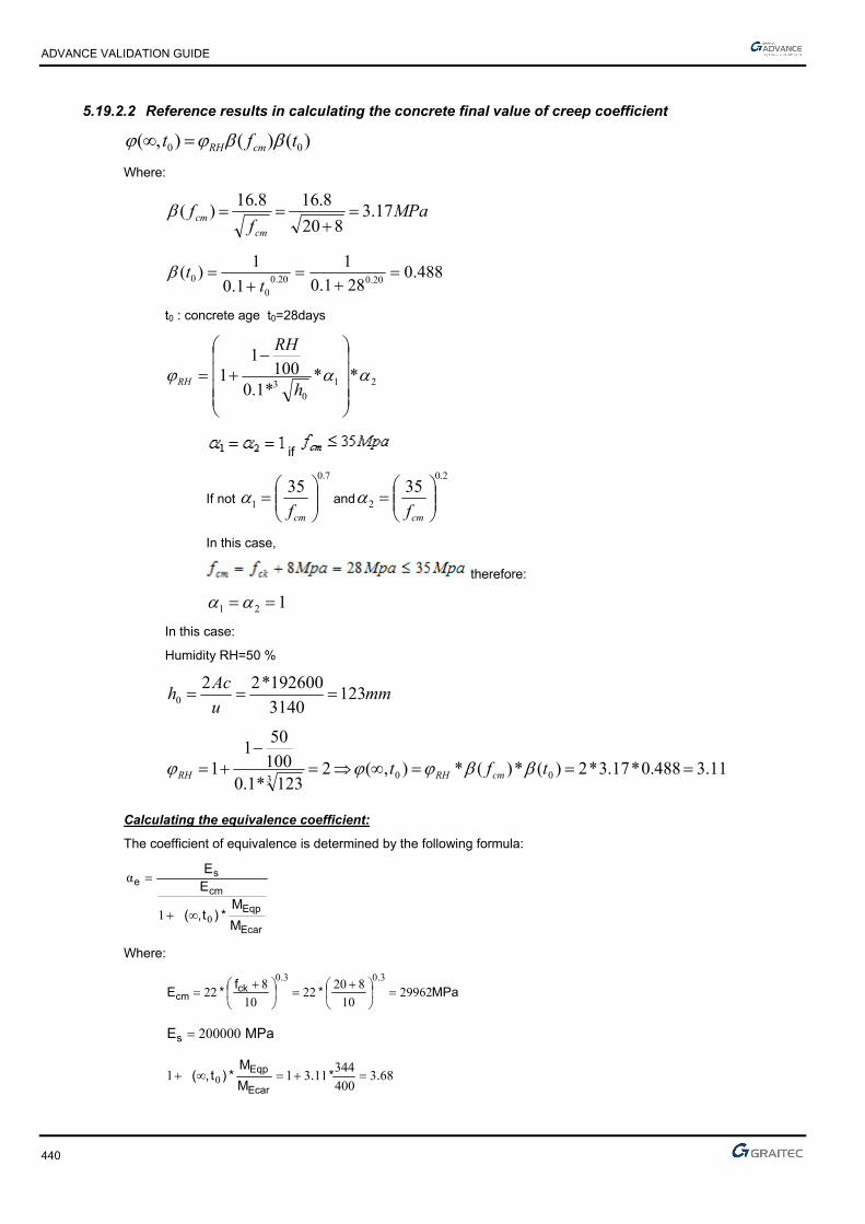
ADVANCE VALIDATION GUIDE
440
5.19.2.2 Reference results in calculating the concrete final value of creep coefficient
)()(),( 00 tft cmRH
Where:
MPaf
fcm
cm 17.3820
8.168.16)(
488.0281.0
1
1.0
1)(
20.020.00
0
t
t
t0 : concrete age t0=28days
21
03
***1.0100
11
h
RH
RH
if
If not
7.0
1
35
cmf and
2.0
2
35
cmf
In this case,
therefore:
121
In this case:
Humidity RH=50 %
mmu
Ach 123
3140
192600*220
11.3488.0*17.3*2)(*)(*),(2123*1.0
100
501
1 003
tft cmRHRH
Calculating the equivalence coefficient:
The coefficient of equivalence is determined by the following formula:
Ecar
Eqp
cm
se
M
M*)t,(
EE
01
α
Where:
MPa*f
*E..
ckcm 29962
10
82022
10
822
3030
MPaEs 200000
683400
34411311 0 .*.
M
M*)t,(
Ecar
Eqp
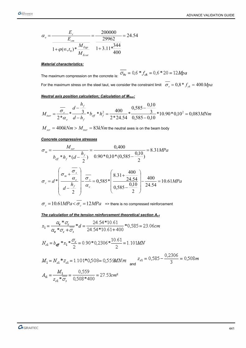
ADVANCE VALIDATION GUIDE
441
54.24
400
344*11.31
29962200000
*),(1 0
Ecar
Eqp
cm
se
M
Mt
EE
Material characteristics:
The maximum compression on the concrete is:
For the maximum stress on the steel taut, we consider the constraint limit
Mpaf yks 400*8,0
Neutral axis position calculation; Calculation of Mtser:
MNmhbhd
hd
M fefff
f
e
stser 083,010,0*90.10*
10,0585,03
10,0585,0
*54.24*2
400**3*
*222
kNmMkNmM tserser 83400 the neutral axes is on the beam body
Concrete compressive stresses
MPah
dhb
M
ffeff
serm 31.8
)2
10,0585,0(*10,0*90.0
400,0
)2
(**
MPah
d
de
s
f
e
sm
c 61.1054.24
400
2
10,0585,0
54.24
40031.8
*585,0
2
*
MPaMPa cc 1261.10 => there is no compressed reinforcement
The calculation of the tension reinforcement theoretical section As1
and

ADVANCE VALIDATION GUIDE
442
Calculation of the steel compressed reinforcement As2:
mhxx f 1306,010,02306,012
MPax
xcc 01.6
2306,0
1306,0*61.1*
1
22
MNxbbN cweffc 282,0
2
01.6*1306,0*)18,090.0(
2*)( 2
22
MNmzNM cc 125,0441,0*282,0* 222
with mzc 441,03
1306,010,0585,02
²06.7400*441,0
125,0
*2
22 cm
z
MA
sc
s
Notions of serviceability moment M0 :
Theoretical steel reinforcement section :
²83.18435,0
400,0*46.20*
0
0 cmM
MAA serss
Reference solution for minimal reinforcement area
The minimum percentage for a rectangular beam in pure bending is:
db
dbf
f
MaxA
w
wyk
effct
s
**0013.0
***26.0 ,
min,
According to: EC2 Part 1,1 EN 1992-1-1-2002 Chapter 9.2.1.1(1); Note 2
Where:
MPaff ctmeffct 21.2, from cracking conditions
Therefore:
²37.1²10*37.1585.0*18.0*0013.0
²10*21.1585.0*18.0*500
21.2*26.0
max4
4
min, cmm
mAs
Finite elements modeling
■ Linear element: S beam,
■ 9 nodes,
■ 1 linear element.

ADVANCE VALIDATION GUIDE
443
SLS load combinations(kNm)
Simply supported beam subjected to bending
SLS (reference value: 400kNm)
Theoretical reinforcement area(cm2)
(reference value: As=18.83cm2)
Minimum reinforcement area(cm2)
(reference value: 1.37cm2)
5.19.2.3 Reference results
Result name Result description Reference value
My,SLS My corresponding to the 102 combination (SLS) [kNm] 400 kNm
Az Theoretical reinforcement area [cm2] 18.83 cm2
Amin Minimum reinforcement area [cm2] 1.37 cm2
5.19.3 Calculated results
Result name Result description Value Error
My My SLS -400 kN*m 0.0000 %
Az Az -18.8948 cm² 0.0001 %
Amin Amin -1.36843 cm² -0.0001 %

ADVANCE VALIDATION GUIDE
444
5.20 EC2 Test 17: Verifying a rectangular concrete beam subjected to a uniformly distributed load, without compressed reinforcement - Inclined stress-strain diagram (Class XD1)
Test ID: 5000
Test status: Passed
5.20.1 Description
Simple Bending Design for Serviceability State Limit
Verifies the adequacy of a rectangular cross section made from concrete C20/25 to resist simple bending. During this test, the determination of stresses is made along with the determination of compressing stresses in concrete section and compressing stresses in the steel reinforcement section.
5.20.2 Background
Simple Bending Design for Serviceability State Limit
Verifies the adequacy of a rectangular cross section made from concrete C20/25 to resist simple bending. During this test, the calculation of stresses is made along with the calculation of compressing stresses in concrete section σc and compressing stresses in the steel reinforcement section σs.
5.20.2.1 Model description
■ Reference: Guide de validation Eurocode 2 EN 1992-1-1-2002;
■ Analysis type: static linear (plane problem);
■ Element type: linear.
The following load cases and load combination are used:
■ Loadings from the structure: G = 9.375 kN/m (including the dead load),
■ Mfq = Mcar = Mqp = 75 kNm
■ Structural class: S4
■ Characteristic combination of actions: CCQ = 1.0 x G
■ Reinforcement steel ductility: Class B
The objective is to verify:
■ The stresses results
■ The compressing stresses in concrete section σc
■ The compressing stresses in the steel reinforcement section σs.
Simply supported beam
Units
Metric System

ADVANCE VALIDATION GUIDE
445
Geometry
Below are described the beam cross section characteristics:
■ Height: h = 0.50 m,
■ Width: b = 0.20 m,
■ Length: L = 8.00 m,
■ Section area: A = 0.10 m2 ,
■ Concrete cover: c=4.5cm
■ Effective height: d=44cm;
Materials properties
Rectangular solid concrete C20/25 is used. The following characteristics are used in relation to this material:
■ Exposure class XD1
■ Stress-strain law for reinforcement: Inclined stress-strain diagram
■ The concrete age t0=28 days
■ Humidity RH=50%
■ Characteristic compressive cylinder strength of concrete at 28 days: Mpafck 20
■ Characteristic yield strength of reinforcement: Mpaf yk 400
■ ²42,9 cmAst for 3 HA20
Boundary conditions
The boundary conditions are described below:
■ Outer:
► Support at start point (x=0) restrained in translation along X, Y and Z,
► Support at end point (x = 8) restrained in translation along Y and Z
■ Inner: None.
Loading
The beam is subjected to the following load combinations:
■ Characteristic combination of actions:
CCQ = 1.0 x G =9.375kN/ml
■ Load calculations:
Mfq = Mcar = Mqp = 75 kNm

ADVANCE VALIDATION GUIDE
446
5.20.2.2 Reference results in calculating the concrete final value of creep coefficient
)()(),( 00 tft cmRH
Where:
MPaf
fcm
cm 17.3820
8.168.16)(
488.0281.0
1
1.0
1)(
20.020.00
0
t
t
t0 : concrete age t0=28days
21
03
***1.0100
11
h
RH
RH
121 if Mpafcm 35
If not,
7.0
1
35
cmf and
2.0
2
35
cmf
In this case,
Therefore 121
In this case:
Humidity RH=50 %
mmu
Ach 86.142
500200*2
500*200*220
03.3488.0*17.3*96.1)(*)(*),(96.186.142*1.0
100
501
1 003
tft cmRHRH
The coefficient of equivalence is determined by the following formula:
Ecar
Eqp
cm
se
M
Mt
EE
*),(1 0

ADVANCE VALIDATION GUIDE
447
Where:
MPaf
E ckcm 29962
10
820*22
10
8*22
3.03.0
MPaEs 200000
03.41*03.31*),(1 0 Ecar
Eqp
M
Mt
90.26
1*03.31
29962200000
*),(1 0
Ecar
Eqp
cm
se
M
Mt
EE
Material characteristics:
The maximum compression on the concrete is: Mpa*,f, ckbc 15256060σ
For the maximum stress on the steel taut, we consider the constraint limit Mpaf*, yks 32080σ
Checking inertia cracked or not:
Before computing the constraints, check whether the section is cracked or not. For this, we determine the cracking moment which corresponds to a tensile stress on the concrete equal to
ctmf :
v
IfM ctm
cr
*
Where:
433
00208,012
50,0*20,0
12
*m
hbI
mh
v 25,02
The average stress in concrete is:
Mpaff ckctm 21,220*30.0*30.0 3
2
3
2
The critical moment of cracking is therefore:
MNmv
IfM ctm
cr 018,025,0
00208,0*21,2*
The servility limit state moment is 0.075MNm therefore the cracking inertia is present.

ADVANCE VALIDATION GUIDE
448
Neutral axis position calculation:
Neutral axis equation: 0)'(**)(**²**2
1111 dxAxdAxb escestw
w
stscewstscestsce
b
AdAdbAAAAx
)*'*(***2)²(*)(* 2
1
By simplifying the previous equation, by considering 0scA , it will be obtained:
w
stewsteste
b
AdbAAx
)****2²*)(* 2
1
cmx 04,2320
)42,9/44(*90,26*20*2²42,9*²90.2642,9*90.261
Calculating the second moment:
443
1
31 001929,0)²230,044,0(*90.26*10*42,9
3
230,0*20,0)²(**
3
*mxdA
xbI est
w
Stresses calculation:
MpaMpaxI
Mc
serc 1294,8230,0*
001929,0
075,0* 1
MpaMpax
xdscest 32057.219
230,0
230,044,0*94,8*90.26**
1
1
Finite elements modeling
■ Linear element: S beam,
■ 9 nodes,
■ 1 linear element.

ADVANCE VALIDATION GUIDE
449
SLS load combinations (kNm) and stresses (MPa)
Simply supported beam subjected to bending
SLS (reference value: Mscq=75kNm)
Compressing stresses in concrete section σc
(reference value: σc =8.94MPa )
Compressing stresses in the steel reinforcement section σs
(reference value: σs=218.57MPa)
5.20.2.3 Reference results
Result name Result description Reference value
My,SLS My corresponding to the 103 combination (SLS) [kNm] 75 kNm
σc Compressing stresses in concrete section σc (MPa) 8.94 MPa
σs Compressing stresses in the steel reinforcement section σs (MPa) 219.67 MPa
5.20.3 Calculated results
Result name Result description Value Error
My My SLS -75 kN*m -0.0000 %
Sc CQ Sc CQ 8.99322 MPa 0.0359 %
Ss CQ Ss CQ -219.639 MPa 0.0006 %

ADVANCE VALIDATION GUIDE
450
5.21 EC2 Test 20: Verifying the crack openings for a rectangular concrete beam subjected to a uniformly distributed load, without compressed reinforcement - Bilinear stress-strain diagram (Class XD1)
Test ID: 5034
Test status: Passed
5.21.1 Description
Simple Bending Design for Serviceability State Limit
Verifies the adequacy of a rectangular cross section made from concrete C25/30 to resist simple bending. During this test, the determination of stresses is made along with the determination of compressing stresses in concrete section and compressing stresses in the steel reinforcement section; the maximum spacing of cracks and the crack openings are verified.
5.21.2 Background
Simple Bending Design for Serviceability State Limit
Verifies the adequacy of a rectangular cross section made from concrete C25/30 to resist simple bending. During this test, the calculation of stresses will be made along with the calculation of compressing stresses in concrete section σc and compressing stresses in the steel reinforcement section σs; maximum spacing of cracks and the crack openings.
5.21.2.1 Model description
■ Reference: Guide de validation Eurocode 2 EN 1992-1-1-2002;
■ Analysis type: static linear (plane problem);
■ Element type: linear.
The following load cases and load combination are used:
■ Loadings from the structure: G = 30 kN/m (including the dead load)
■ Exploitation loadings (category A): Q = 37.5 kN/m,
■ Structural class: S4
■ Reinforcement steel ductility: Class B
The objective is to verify:
■ The stresses results
■ The compressing stresses in concrete section σc
■ The compressing stresses in the steel reinforcement section σs.
■ The maximum spacing of cracks
■ The crack opening
Simply supported beam

ADVANCE VALIDATION GUIDE
451
Units
Metric System
Geometry
Beam cross section characteristics:
■ Height: h = 0.80 m,
■ Width: b = 0.40 m,
■ Length: L = 8.00 m,
■ Section area: A = 0.32 m2 ,
■ Concrete cover: c=4.5cm
■ Effective height: d=71cm;
Materials properties
Rectangular solid concrete C25/30 is used. The following characteristics are used in relation to this material:
■ Exposure class XD1
■ Stress-strain law for reinforcement: Bilinear stress-strain diagram
■ The concrete age t0=28 days
■ Humidity RH=50%
■ Characteristic compressive cylinder strength of concrete at 28 days: Mpafck 25
■ Characteristic yield strength of reinforcement: Mpafyk 500
■ ²cm.Ast 1630 for 3 beds of 5HA16
Boundary conditions
The boundary conditions are described below:
■ Outer:
► Support at start point (x=0) restrained in translation along X, Y and Z,
► Support at end point (x = 8) restrained in translation along Y and Z
■ Inner: None.
Loading
The beam is subjected to the following load combinations:
■ Load calculations:
► M0Ed = 774 kNm
► Mcar = 540 kNm
► Mfq = 390 kNm
► Mqp = 330 kNm
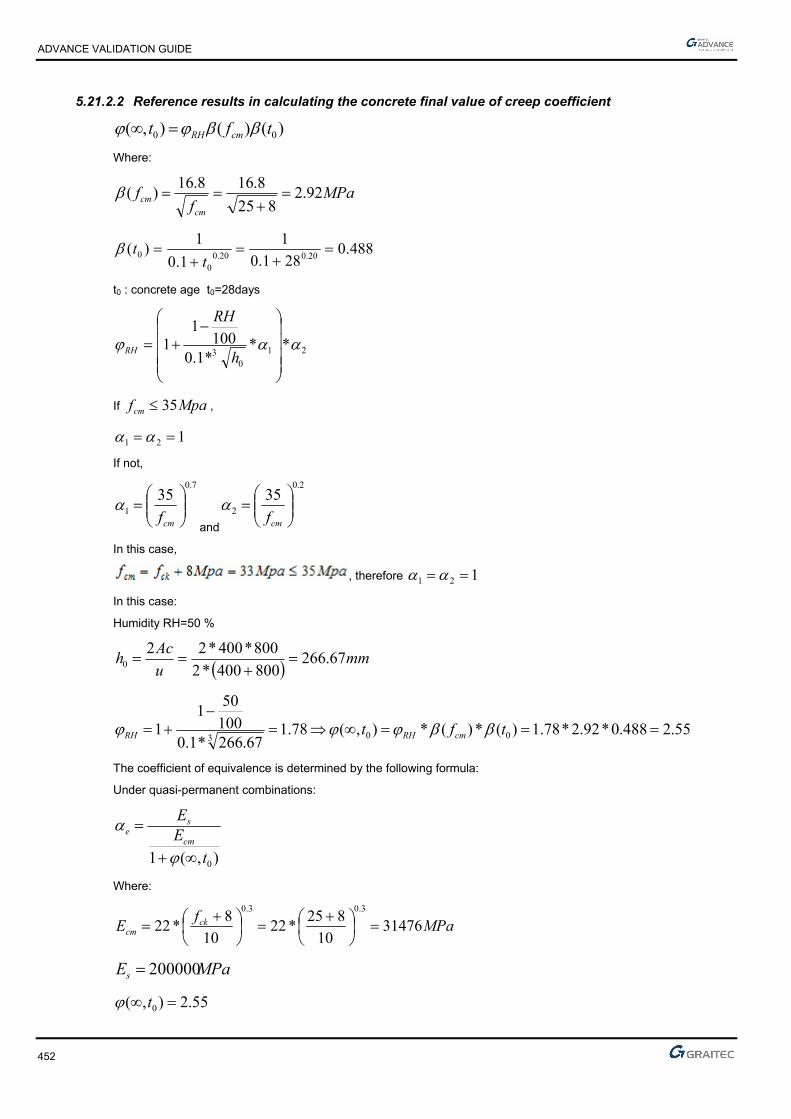
ADVANCE VALIDATION GUIDE
452
5.21.2.2 Reference results in calculating the concrete final value of creep coefficient
)()(),( 00 tft cmRH
Where:
MPaf
fcm
cm 92.2825
8.168.16)(
488.0281.0
1
1.0
1)(
20.020.00
0
t
t
t0 : concrete age t0=28days
21
03
***1.0100
11
h
RH
RH
If Mpafcm 35 ,
121
If not,
7.0
1
35
cmf
and
2.0
2
35
cmf
In this case,
, therefore 121
In this case:
Humidity RH=50 %
mmu
Ach 67.266
800400*2
800*400*220
55.2488.0*92.2*78.1)(*)(*),(78.167.266*1.0
100
501
1 003
tft cmRHRH
The coefficient of equivalence is determined by the following formula:
Under quasi-permanent combinations:
),(1 0t
EE
cm
se
Where:
MPaf
E ckcm 31476
10
825*22
10
8*22
3.03.0
MPaEs 200000
55.2),( 0 t

ADVANCE VALIDATION GUIDE
453
56.22
55.21
31476200000
),(1 0
t
EE
cm
se
Material characteristics:
The maximum compression on the concrete is: Mpafckbc 1525*6,06,0
For the maximum stress on the steel taut, we consider the constraint limit Mpaf yks 400*8,0
Neutral axis position calculation:
Neutral axis equation: 0αα2
1111 )'dx(**A)xd(**A²x*b* escestw
w
stscewstscestsce
b
)A*dA'*d(**b*)²AA(*)AA(*x
α2αα 2
1
By simplifying the previous equation, by considering 0scA , it will be obtained:
cm.**.**².*²..*.
b
)A*d**b*²A*A*x stewsteste
3540
16307156224021630562216305622
α2αα 2
1
Calculating the second moment:
443
11
31
01450350071056221016303
350040
αα3
m.)²..(*.**,.*.
)²'dx(**A)²xd(**Ax*b
I escestw
Stresses calculation:
MpaxI
Mserc 96.7350,0*
0145,0
330,0* 1
MpaMpax
xdscest 4007.184
350,0
350,071,0*96.7*56.22**
1
1

ADVANCE VALIDATION GUIDE
454
Maximum spacing of cracks:
Bottom reinforcement 3HA20+3HA16=15.46cm2
2, 06.015.0*4.0
4.02
8.0
15.03
)350.08.0(255.0)71.08.0(*5.2
min*40.0
2
3
)()(*5.2
min* m
h
xhdh
bA effc
According to: EC2 Part 1,1 EN 1992-1-1-2002 Chapter 7.3.4.(2); Figure 7.1
0500.006.0
10*16.30 4
,,
effc
seffp A
A
mmnn
nneq 16
**
**
2211
222
211
According to: EC2 Part 1,1 EN 1992-1-1-2002 Chapter 7.3.4.(3)
effpr
kkcks
,
213max,
***425.0*
Where:
c=0.051m
113.251
25*4.3
25*4.3
3/23/2
3
c
k
Therefore:
mmkk
ckseffp
r 162050.0
)10*16(*5.0*8.0*425.0051.0*113.2
***425.0*
3
,
213max,
Calculation of average strain:
41.631187
200000
cm
se E
E
44
,,
,
10*54.5*6,010*88.7200000
)050.0*41.61(*050.0
56.2*4.071.184).1(**
s
s
s
effpeeffp
effctts
cmsm EE
fk
According to: EC2 Part 1,1 EN 1992-1-1-2002 Chapter 7.3.4.(2)
Calculation of crack widths:
mmsw cmsmrk 128.0)1088.7(*162.0)(* 4max,
According to: EC2 Part 1,1 EN 1992-1-1-2002 Chapter 7.3.4.(1)
For an exposure class XD1, using the French national annex, we retained an opening crack of 0.20mm max.
This criterion is satisfied.

ADVANCE VALIDATION GUIDE
455
Finite elements modeling
■ Linear element: S beam,
■ 11 nodes,
■ 1 linear element.
SLS load combinations (kNm) and stresses (MPa)
Simply supported beam subjected to bending
ULS (reference value: MEd=774kNm)
SLS characteristic (reference value: Mser-cq=540kNm)
SLS quasi-permanent (reference value: Mser-qp=330kNm)
Compressing stresses in concrete section σc-qp
(reference value: σc-qp =7.96MPa )
Compressing stresses in the steel reinforcement section σs-qp
(reference value: σs-qp=185MPa)

ADVANCE VALIDATION GUIDE
456
Maximum cracking space Sr,max
(reference value: Sr,max=162mm)
Maximum crack opening Wk
(reference value: Wk=0.128mm)
5.21.2.3 Reference results
Result name Result description Reference value
MEd My corresponding to 102 combination (ULS) [kNm] 774 kNm
Mser-cq My corresponding to104 combination (SLS) [kNm] 540 kNm
Mser-qp My corresponding to 108 combination (SLS) [kNm] 330 kNm
σc Compressing stresses in concrete section σc [MPa] 7.96 MPa
σs Compressing stresses in the steel reinforcement section σs [MPa] 185 Mpa
Sr,max Maximum cracking space Sr,max [cm] 16.2 cm
Wk Maximum crack opening Wk [cm] 0.0128 cm
5.21.3 Calculated results
Result name Result description Value Error
My My ULS -774 kN*m 0.0000 %
My My SLS cq -540 kN*m 0.0000 %
My My SLS qp -330 kN*m 0.0000 %
Sc QP Sc QP 7.76924 MPa 0.0000 %
Ss QP Ss QP -181.698 MPa 0.0001 %
Sr,max Sr,max 16.1577 cm -0.0003 %
wk Wk -0.0125137 cm 0.0000 %
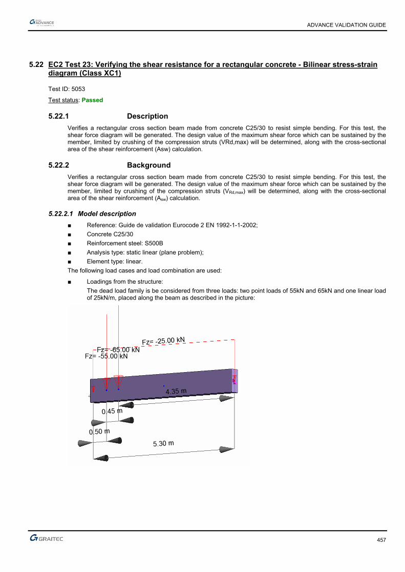
ADVANCE VALIDATION GUIDE
457
5.22 EC2 Test 23: Verifying the shear resistance for a rectangular concrete - Bilinear stress-strain diagram (Class XC1)
Test ID: 5053
Test status: Passed
5.22.1 Description
Verifies a rectangular cross section beam made from concrete C25/30 to resist simple bending. For this test, the shear force diagram will be generated. The design value of the maximum shear force which can be sustained by the member, limited by crushing of the compression struts (VRd,max) will be determined, along with the cross-sectional area of the shear reinforcement (Asw) calculation.
5.22.2 Background
Verifies a rectangular cross section beam made from concrete C25/30 to resist simple bending. For this test, the shear force diagram will be generated. The design value of the maximum shear force which can be sustained by the member, limited by crushing of the compression struts (VRd,max) will be determined, along with the cross-sectional area of the shear reinforcement (Asw) calculation.
5.22.2.1 Model description
■ Reference: Guide de validation Eurocode 2 EN 1992-1-1-2002;
■ Concrete C25/30
■ Reinforcement steel: S500B
■ Analysis type: static linear (plane problem);
■ Element type: linear.
The following load cases and load combination are used:
■ Loadings from the structure:
The dead load family is be considered from three loads: two point loads of 55kN and 65kN and one linear load of 25kN/m, placed along the beam as described in the picture:

ADVANCE VALIDATION GUIDE
458
■ Exploitation loadings:
The live load will consist of three loads: two point loads of 40kN and 35kN and one linear load of 20kN/m, placed along the beam as described in the picture:
■ Structural class: S1
■ Reinforcement steel ductility: Class B
■ The reinforcement will be displayed like in the picture below:
The objective is to verify:
■ The shear stresses results
■ The cross-sectional area of the shear reinforcement, Asw
■ The theoretical reinforcement value
Units
Metric System
Geometry
Below are described the beam cross section characteristics:
■ Height: h = 0.70 m,
■ Width: b = 0.30 m,
■ Length: L = 5.30 m,
■ Concrete cover: c=3.5cm
■ Effective height: d=h-(0.06*h+ebz)=0.623m; d’=ehz=0.0335m
■ Stirrup slope: = 90°
■ Stirrup slope: 45˚

ADVANCE VALIDATION GUIDE
459
Boundary conditions
The boundary conditions are described below:
■ Outer:
► Support at start point (x = 0) restrained in translation along X, Y and Z,
► Support at end point (x = 5.30) restrained in translation along Y, Z and rotation along X
■ Inner: None.
Loading
The maximum shear stresses from the concrete beam:
Using the software structure calculation the following values were obtained:
x = 0m => KNVEd 406
x = 0.50m (for the first point load) => KN.VEd 76373 and KN.VEd 51239
x = 0.95m (for the second point load) => KN.VEd 82210 and KN.VEd 5770
x = 2.06m the shear force is null => KNVEd 0
Note: In Advance Design, the shear reduction is not taken into account. These are the values corresponding to an unreduced shear that will be used for further calculations.
ADVANCE VALIDATION GUIDE
460
5.22.2.2 Reference results in calculating the maximum design shear resistance
21max, cot1
cotcot*****
wucdcwRd bzfV
According to: EC2 Part 1,1 EN 1992-1-1-2002 Chapter 6.2.3.(3)
Where:
1cw coefficient taking account of the state of the stress in the compression chord and
2501*6,01
ckfv
When the transverse frames are vertical, the above formula simplifies to:
cot
***1max,
tg
bzfvV wucdRd
In this case:
45 and 90
1v strength reduction factor for concrete cracked in shear
54.0250
251*6.0
2501*6,01
ckfv
mdzu 561.0623.0*9.0*9.0
MNVRd 757.02
30.0*561.0*67.16*54.0max,
MNVMNV RdEd 757.0406.0 max,
Calculation of transversal reinforcement:
Is determined by considering the transverse reinforcement steels vertical ( = 90°) and connecting rods inclined at 45 °, at different points of the beam.
Before the first point load:
mlcmtg
fz
tgV
s
A
ywdu
Edsw /²65,16
15,1
500*561,0
45*406,0
*
*.
Between the first and the second point load:
mlcmtg
s
Asw /²82,9
15,1
500*561,0
45*23951,0
It also calculates the required reinforcement area to the right side of the beam:
mlcmtg
s
Asw /²48,8
15,1
500*561,0
45*20674,0
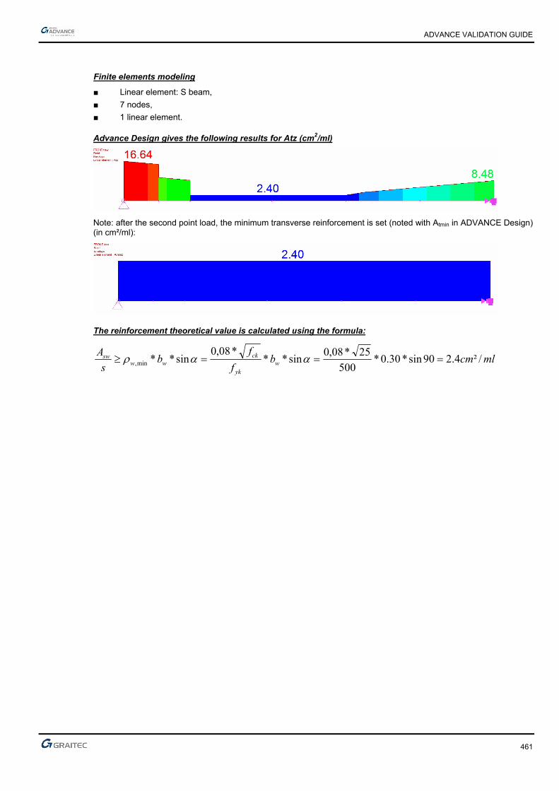
ADVANCE VALIDATION GUIDE
461
Finite elements modeling
■ Linear element: S beam,
■ 7 nodes,
■ 1 linear element.
Advance Design gives the following results for Atz (cm2/ml)
Note: after the second point load, the minimum transverse reinforcement is set (noted with Atmin in ADVANCE Design) (in cm²/ml):
The reinforcement theoretical value is calculated using the formula:
mlcmbf
fb
s
Aw
yk
ckww
sw /²4.290sin*30.0*500
25*08,0sin**
*08,0sin**min,
ADVANCE VALIDATION GUIDE
462
5.22.2.3 Reference results
Result name Result description Reference value
Fz Fz corresponding to 101 combination (ULS) x=0m [kN] 405.63 kN
Fz Fz corresponding to 101 combination (ULS) x=0.5m [kN] 373.76 kN
Fz Fz corresponding to 101 combination (ULS) x=0.501m [kN] 239.51 kN
Fz Fz corresponding to 101 combination (ULS) x=0.95m [kN] 210.82 kN
Fz Fz corresponding to 101 combination (ULS) x=0.9501m [kN] 70.57 kN
Atz Transversal reinforcement area x=0m [cm2/ml] 16,65 cm2/ml
Atz Transversal reinforcement area x=0.501m [cm2/ml] 9.82 cm2/ml
Atz Transversal reinforcement area x=5.3m [cm2/ml] 8.84 cm2/ml
At,min,z Theoretical reinforcement area [cm2/ml] 2.40 cm2/ml
5.22.3 Calculated results
Result name Result description Value Error
Fz Fz,0 -405.633 kN -0.0001 %
Fz Fz,1 -373.758 kN -0.0001 %
Fz Fz,1' -239.445 kN 0.0002 %
Fz Fz,2 -210.821 kN 0.0001 %
Fz Fz,2' -70.5644 kN -0.0001 %
Atz Atz,0 16.6391 cm² 0.0002 %
Atz Atz,1 9.82205 cm² 0.0000 %
Atz Atz,r 8.48058 cm² -0.0000 %
Atminz At,min,z 2.4 cm² 0.0000 %
ADVANCE VALIDATION GUIDE
463
5.23 EC2 Test 10: Verifying a T concrete section, without compressed reinforcement - Inclined stress-strain diagram
Test ID: 4984
Test status: Passed
5.23.1 Description
Simple Bending Design for Ultimate Limit State - The purpose of this test is to verify the My resulted stresses for the ULS load combination, the results of the theoretical reinforcement area, "Az" and the minimum reinforcement percentage, "Amin".
This test performs the verification of the theoretical reinforcement area for the T concrete beam subjected to the defined loads. The test confirms the absence of the compressed reinforcement for this model.
5.23.2 Background
Verifies the theoretical reinforcement area for the T concrete beam subjected to the defined loads. The test confirms the absence of the compressed reinforcement for this model.
5.23.2.1 Model description
■ Reference: Guide de validation Eurocode 2 EN 1992-1-1-2002;
■ Analysis type: static linear (plane problem);
■ Element type: linear.
The following load cases and load combination are used:
■ Loadings from the structure: G = 500 kN/m
■ Exploitation loadings (category A): Q = 300kN/m,
■ The ultimate limit state (ULS) combination is: Cmax = 1.35 x G + 1.5 x Q
■ Characteristic combination of actions: CCQ = 1.0 x G + 1.0 x Q
■ Quasi-permanent combination of actions: CQP = 1.0 x G + 0.3 x Q
■ 30ψ2 ,
■ Reinforcement steel ductility: Class B
■ The calculation is performed considering inclined stress-strain diagram
The objective is to verify:
■ The stresses results
■ The theoretical reinforcement area
■ The reinforcement minimum percentage area
Simply supported beam

ADVANCE VALIDATION GUIDE
464
Units
Metric System
Geometry
Below are described the beam cross section characteristics:
■ Beam length: 6m
■ Concrete cover: c=4.00 cm
■ Effective height: d=h-(0.6*h+ebz)=0.900 m; d’=ebz=0.04m
Materials properties
Rectangular solid concrete C30/37 and S500B reinforcement steel is used. The following characteristics are used in relation to this material:
■ Exposure class XC2
■ Reinforcement steel ductility: Class B
■ The calculation is made considering the inclined stress-strain diagram
■ Concrete C16/20:
MPa,
ff
c
ckcd 20
51
30
γ
According to: EC2 Part 1,1 EN 1992-1-1-2002 Chapter 3.1.6(1); 4.4.2.4(1); Table 2.1.N
MPa.*.f*.f //ckctm 90230300300 3232
According to: EC2 Part 1,1 EN 1992-1-1-2002 Chapter 3.1.3(2); Table 3.1
■ Steel S400B :
MPa.,
ff
s
ykyd 78434
151
500
γ
According to: EC2 Part 1,1 EN 1992-1-1-2002 Chapter 3.2
Boundary conditions
The boundary conditions are described below:
■ Outer:
► Support at start point (x = 0) restrained in translation along X, Y and Z,
► Support at end point (x = 7) restrained in translation along Y and Z, and restrained rotation along X.
■ Inner: None.

ADVANCE VALIDATION GUIDE
465
Loading
The beam is subjected to the following load combinations:
Load combinations:
The ultimate limit state (ULS) combination is:
Cmax = 1.35 x G + 1.5 x Q=1.35*500+1.5*300=1125 kN/m
Characteristic combination of actions:
CCQ = 1.0 x G + 1.0 x Q=500+300=800 kN/m
Quasi-permanent combination of actions
CQP = 1.0 x G + 0.3 x Q=500+0.3*300=590 kN/m
Load calculations:
kNm.²*
MEd 550628
61125
kNm²*
MEcq 36008
6800
kNm²*
MEqp 26558
6590
5.23.2.2 Reference results in calculating the concrete beam moment
At first it will be determined the moment resistance of the concrete section only:
kNm*.*,
,*,*.f*h
d*h*bM cdf
feffbtu310480420
2
20090200401
2
Comparing Mbtu with MEd:
Therefore the concrete section is not entirely compressed;
There are required calculations considering the T section.
Reference reinforcement calculation:
For those calculations, the beam section will be divided in two theoretical section:
Section 1: For the calculation of the concrete only
Section 2: For the calculation of the compressed reinforcement
Theoretical section 2:
The moment corresponding to this section is:
kNm*.
..**.*)..(
hd*f*h*)bb(M f
cdfweffEd
3
2
1023
2
20090020200400401
2
Stress from the compressed steel reinforcement considering a steel grade S500B:
MPa*,, susu 466ε2772771432σ
In order to determine the suε , the neutral axis position must be determined:
kNm*.*)..(MMM EdEdEd33
21 1086311020030635
28702090400
8631μ 1 .
*².*.
.
F*²d*b
M
cdw
Edcu
kNm*.MkNm*.M Edbtu33 1006255104804
ADVANCE VALIDATION GUIDE
466
43502870211251μ211251α ..**.)*(*. cuu
Depending of uα , the neutral axis position can be established:
5545034350
43501ε
α
α1ε 2 ..*
.
.* cu
u
usu
‰
Then we calculate the stress in the tensioned steel reinforcement:
MPaMPa,.,,su 466024360045502772771432σ
According to those above, the theoretical reinforcement can be calculated:
²cm.
.*.
.
.
F*h
d
MA
ydf
Ed 7491
024362
20090
2003
2
22
Theoretical section 1:
The theoretical section 1 corresponds to a calculation for a rectangular shape beam section
kNm*.*)..(MMM EdEdEd33
21 1086311020030635
3720μ28702090400
8631μ 1 ..
*².*.
.
F*²d*b
Mlu
cdw
Edcu
For a S500B reinforcement and for a XC2 exposure class, there will be a: 3720μ2870μ .. lucu , therefore there will be
no compressed reinforcement.
There will be a calculation without compressed reinforcement:
43502870211251μ211251α ..**.)*(*. cuu
m.).*.(*.)*.(*dz uc 74304350400190α4011
²cm..*.
.
f*z
MA
ydc
Ed 4657024367430
8631
1
11
Theoretical section 1:
In conclusion the entire reinforcement steel area is A=A1+A2=91.74+57.46=149.20cm2
Reference solution for minimal reinforcement area
The minimum percentage for a rectangular beam in pure bending is:
d*b*.
d*b*f
f*.
MaxA
w
wyk
eff,ct
min,s
00130
260
According to: EC2 Part 1,1 EN 1992-1-1-2002 Chapter 9.2.1.1(1); Note 2
Where:
MPa.ff ctmeff,ct 902 from cracking conditions
Therefore:
²cm.
²m*..*.*.
²m*..*.*.
*.maxA min,s 425
1068490040000130
10425900400500
902260
4
4
Finite elements modeling
■ Linear element: S beam,
■ 7 nodes,
■ 1 linear element.

ADVANCE VALIDATION GUIDE
467
ULS and SLS load combinations (kNm)
Simply supported beam subjected to bending
ULS (reference value: 5062.5kNm)
Theoretical reinforcement area(cm2)
For Class B reinforcement steel ductility (reference value: A=149.20cm2)
Minimum reinforcement area(cm2)
(reference value: 5.42cm2)
5.23.2.3 Reference results
Result name Result description Reference value
My,ULS My corresponding to the 101 combination (ULS) [kNm] 5062.5 kNm
Az (Class B) Theoretical reinforcement area [cm2] 149.20 cm2
Amin Minimum reinforcement area [cm2] 5.42 cm2
5.23.3 Calculated results
Result name Result description Value Error
My My USL -5062.5 kN*m 0.0000 %
Az Az -149.031 cm² 0.0001 %
Amin Amin -5.42219 cm² 0.0000 %

ADVANCE VALIDATION GUIDE
468
5.24 EC2 Test 15: Verifying a T concrete section, without compressed reinforcement- Bilinear stress-strain diagram
Test ID: 4998
Test status: Passed
5.24.1 Description
Simple Bending Design for Service Limit State
The purpose of this test is to verify the My resulted stresses for the SLS load combination and the results of the theoretical reinforcement area Az and of the minimum reinforcement percentage.
5.24.2 Background
This test performs the verification of the theoretical reinforcement area for a T concrete beam subjected to the defined loads. The test confirms the absence of the compressed reinforcement for this model.
5.24.2.1 Model description
■ Reference: Guide de validation Eurocode 2 EN 1992-1-1-2002;
■ Analysis type: static linear (plane problem);
■ Element type: linear.
The following load cases and load combination are used:
■ Loadings from the structure: G = 20 kN/m (including the dead load)
■ Exploitation loadings (category A): Q = 10kN/m,
■ Characteristic combination of actions: CCQ = 1.0 x G + 1.0 x Q
■ Quasi-permanent combination of actions: CQP = 1.0 x G + 0.3 x Q
■ Reinforcement steel ductility: Class A
■ The calculation is performed considering bilinear stress-strain diagram
The objective is to verify:
■ The stresses results
■ The theoretical reinforcement area
■ The minimum reinforcement percentage
Simply supported beam
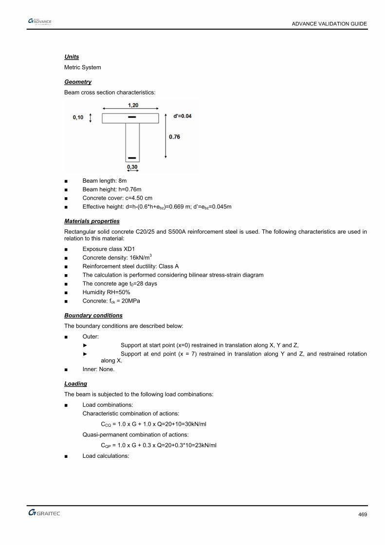
ADVANCE VALIDATION GUIDE
469
Units
Metric System
Geometry
Beam cross section characteristics:
■ Beam length: 8m
■ Beam height: h=0.76m
■ Concrete cover: c=4.50 cm
■ Effective height: d=h-(0.6*h+ebz)=0.669 m; d’=ebz=0.045m
Materials properties
Rectangular solid concrete C20/25 and S500A reinforcement steel is used. The following characteristics are used in relation to this material:
■ Exposure class XD1
■ Concrete density: 16kN/m3
■ Reinforcement steel ductility: Class A
■ The calculation is performed considering bilinear stress-strain diagram
■ The concrete age t0=28 days
■ Humidity RH=50%
■ Concrete: fck = 20MPa
Boundary conditions
The boundary conditions are described below:
■ Outer:
► Support at start point (x=0) restrained in translation along X, Y and Z,
► Support at end point (x = 7) restrained in translation along Y and Z, and restrained rotation along X.
■ Inner: None.
Loading
The beam is subjected to the following load combinations:
■ Load combinations:
Characteristic combination of actions:
CCQ = 1.0 x G + 1.0 x Q=20+10=30kN/ml
Quasi-permanent combination of actions:
CQP = 1.0 x G + 0.3 x Q=20+0.3*10=23kN/ml
■ Load calculations:

ADVANCE VALIDATION GUIDE
470
kNmM cqser 240
8
²8*1020,
kNmM qpser 184
8
²8*10*3.020,
5.24.2.2 Reference results in calculating the concrete final value of the creep coefficient
)()(),( 00 tft cmRH
Where:
MPaf
fcm
cm 17.3820
8.168.16)(
488.0281.0
1
1.0
1)( 20.020.0
0
0
t
t
t0 : concrete age t0=28days
21
03
***1.0100
11
h
RH
RH
121 if Mpafcm 35
If not
7.0
1
35
cmf and
2.0
2
35
cmf
In this case MpaMpaMpaff ckcm 35288 therefore
121
In this case:
Humidity RH=50 %
mmu
Ach 24.162
3920
318000*220
97.2488.0*17.3*92.1)(*)(*),(92.124.162*1.0
100
501
1 003
tft cmRHRH
Calculating the equivalence coefficient:
The coefficient of equivalence is determined by the following formula:
Ecar
Eqp
cm
se
M
Mt
EE
*),(1 0

ADVANCE VALIDATION GUIDE
471
Where:
MPaf
E ckcm 29962
10
820*22
10
8*22
3.03.0
MPaEs 200000
28.3240
184*97.21*),(1 0
Ecar
Eqp
M
Mt
89.21
240
184*97.21
2962200000
*),(1 0
Ecar
Eqp
cm
se
M
Mt
EE
Material characteristics:
The maximum compression on the concrete is: Mpafckbc 1220*6,0*6,0
For the maximum stress on the steel taut, we consider the constraint limit Mpaf yks 400*8,0
Neutral axis position calculation; Calculation of Mtser:
MNmhbhd
hd
M fefff
f
e
stser 122,010,0*20,1*
10,0669,03
10,0669,0
*77.43
400**3*
*222
kNmMkNmM tserser 122240 the neutral axes is on the beam body
Concrete compressive stresses
MPah
dhb
M
ffeff
serm 23,3
)2
10,0669,0(*10,0*20,1
240,0
)2
(**
MPah
d
de
s
f
e
sm
c 96,489.21
400
2
10,0669,0
89.21
40023,3
*669,0
2
*
MPaMPa cc 1296.4 => there is no compressed reinforcement

ADVANCE VALIDATION GUIDE
472
The calculation of the tension reinforcement theoretical section As1
cmdxsce
ce 30.14669,0*40096,4*89.21
96,4*89.21
*
*1
MNxbN ceffc 426,0
2
96,4*1430,0*20,1
2** 11
m.MN,,*,z*NM cc 265062204260111 and m,,
,zc 62203
1430066901
²65,10400*622,0
265,0
*1
11 cmz
MA
sc
s
Calculation of the steel compressed reinforcement As2:
m,,,hxx f 043001001430012
MPa,,
,*,
x
x*cc 491
14300
04300964σσ
1
22
MN,,
*,*),,(x*)bb(N cweffc 0290
2
4910430030201
2
σ 222
MNm,,*,z*NM cc 016055500290222
with m,,
,,zc 55503
0430010066902
²cm,*,
,
*z
MA
scs 720
4005550
0160
σ2
22
Notions of serviceability moment M0 :
²cm...AAA sss 9397206510210
m.MN,,,MMM 249001602650210
Theoretical steel reinforcement section :
²cm,,
,*,
M
M*AA sers
s 5892490
2400939
0
0
Reference solution for minimal reinforcement area
The minimum percentage for a rectangular beam in pure bending is:
d*b*.
d*b*f
f*.
MaxA
w
wyk
eff,ct
min,s
00130
260
According to: EC2 Part 1,1 EN 1992-1-1-2002 Chapter 9.2.1.1(1); Note 2
Where:
MPa.ff ctmeff,ct 212 from cracking conditions
Therefore:
²cm.
²m*..*.*.
²m*..*.*.
*.maxA min,s 612
10612669030000130
103126690300500
212260
4
4

ADVANCE VALIDATION GUIDE
473
Finite elements modeling
■ Linear element: S beam,
■ 9 nodes,
■ 1 linear element.
SLS load combinations(kNm)
Simply supported beam subjected to bending
SLS (reference value: 240kNm)
Theoretical reinforcement area (cm2)
(reference value: As=9.58cm2)
Minimum reinforcement area (cm2)
(reference value: 2.57cm2)

ADVANCE VALIDATION GUIDE
474
5.24.2.3 Reference results
Result name Result description Reference value
My,SLS My corresponding to the 102 combination (SLS) [kNm] 240 kNm
Az Theoretical reinforcement area [cm2] 9.58 cm2
Amin Minimum reinforcement area [cm2] 2.57 cm2
5.24.3 Calculated results
Result name Result description Value Error
My My SLS -240 kN*m 0.0000 %
Az Az -9.64217 cm² -0.6490 %
Amin Amin -2.574 cm² -0.0000 %

ADVANCE VALIDATION GUIDE
475
5.25 EC2 Test 19: Verifying the crack openings for a rectangular concrete beam subjected to a uniformly distributed load, without compressed reinforcement - Bilinear stress-strain diagram (Class XD1)
Test ID: 5033
Test status: Passed
5.25.1 Description
Simple Bending Design for Serviceability State Limit
Verifies the adequacy of a rectangular cross section made from concrete C25/30 to resist simple bending. During this test, the determination of stresses is made along with the determination of compressing stresses in concrete section and compressing stresses in the steel reinforcement section; the maximum spacing of cracks and the crack openings are verified.
5.25.2 Background
Simple Bending Design for Serviceability State Limit
Verifies the adequacy of a rectangular cross section made from concrete C25/30 to resist simple bending. During this test, the calculation of stresses will be made along with the calculation of compressing stresses in concrete section σc and compressing stresses in the steel reinforcement section σs; maximum spacing of cracks and the crack openings.
5.25.2.1 Model description
■ Reference: Guide de validation Eurocode 2 EN 1992-1-1-2002;
■ Analysis type: static linear (plane problem);
■ Element type: linear.
The following load cases and load combination are used:
■ Loadings from the structure: G = 15 kN/m + dead load,
■ Exploitation loadings (category A): Q = 20 kN/m,
■ Structural class: S4
■ Reinforcement steel ductility: Class B
The objective is to verify:
■ The stresses results
■ The compressing stresses in concrete section σc
■ The compressing stresses in the steel reinforcement section σs.
■ The maximum spacing of cracks
■ The crack opening
Simply supported beam
ADVANCE VALIDATION GUIDE
476
Units
Metric System
Geometry
Beam cross section characteristics:
■ Height: h = 0.60 m,
■ Width: b = 0.20 m,
■ Length: L = 5.80 m,
■ Section area: A = 0.12 m2 ,
■ Concrete cover: c=4.5cm
■ Effective height: d=53cm;
Materials properties
Rectangular solid concrete C25/30 is used. The following characteristics are used in relation to this material:
■ Exposure class XD1
■ Stress-strain law for reinforcement: Bilinear stress-strain diagram
■ The concrete age t0=28 days
■ Humidity RH=50%
■ Characteristic compressive cylinder strength of concrete at 28 days: Mpafck 25
■ Characteristic yield strength of reinforcement: Mpafyk 500
■ ²cm.Ast 4615 for 3 HA20+3 HA16
Boundary conditions
The boundary conditions are described below:
■ Outer:
► Support at start point (x = 0) restrained in translation along X, Y and Z,
► Support at end point (x = 8) restrained in translation along Y and Z
■ Inner: None.
Loading
The beam is subjected to the following load combinations:
■ Load calculations:
► M0Ed = 228 kNm
► Mcar = 160 kNm
► Mfq = 118 kNm
► Mqp = 101 kNm

ADVANCE VALIDATION GUIDE
477
5.25.2.2 Reference results in calculating the concrete final value of creep coefficient
)()(),( 00 tft cmRH
Where:
MPaf
fcm
cm 92.2825
8.168.16)(
488.0281.0
1
1.0
1)(
20.020.00
0
t
t
t0 : concrete age t0=28days
21
03
***1.0100
11
h
RH
RH
121 if Mpafcm 35
If not
7.0
1
35
cmf
and
2.0
2
35
cmf
In this case,
, therefore:
In this case:
Humidity RH=50 %
mmu
Ach 150
600200*2
600*200*220
77.2488.0*92.2*94.1)(*)(*),(94.1150*1.0
100
501
1 003
tft cmRHRH
The coefficient of equivalence is determined by the following formula:
Ecar
Eqp
cm
se
M
Mt
EE
*),(1 0
ADVANCE VALIDATION GUIDE
478
Where:
MPaf
E ckcm 31476
10
825*22
10
8*22
3.03.0
MPaEs 200000
75.2160
101*77.21*),(1 0
Ecar
Eqp
M
Mt
75.2
160
101*77.21
31476200000
*),(1 0
Ecar
Eqp
cm
se
M
Mt
EE
Material characteristics:
The maximum compression on the concrete is: Mpafckbc 1525*6,06,0
For the maximum stress on the steel taut, we consider the constraint limit Mpaf yks 320*8,0
Neutral axis position calculation:
Neutral axis equation: 0αα2
1111 )'dx(**A)xd(**A²x*b* escestw
w
stscewstscestsce
b
)A*dA'*d(**b*)²AA(*)AA(*x
α2αα 2
1
By simplifying the previous equation, by considering 0scA , it will be obtained:
cm..**.**².*²..*.
b
)A*d**b*²A*A*x stewsteste
672620
46155347172024615471746154717
α2αα 2
1
Calculating the second moment:
443
11
31
003140267053047171046153
267020
αα3
m.)²..(*.**,.*.
)²'dx(**A)²xd(**Ax*b
I escestw
Stresses calculation:
MpaxI
Mserc 59.8267,0*
00314,0
101,0* 1
MpaMpax
xdscest 40082.147
267,0
267,053,0*59.8*47.17**
1
1

ADVANCE VALIDATION GUIDE
479
Maximum spacing of cracks:
Bottom reinforcement 3HA20+3HA16=15.46cm2
2, 0222.0111.0*2.0
3.02
6.0
111.03
)267.06.0(175.0)53.06.0(*5.2
min*20.0
2
3
)()(*5.2
min* m
h
xhdh
bA effc
According to: EC2 Part 1,1 EN 1992-1-1-2002 Chapter 7.3.4.(2); Figure 7.1
070.00222.0
10*46.15 4
,,
effc
seffp A
A
mmnn
nneq 22.18
**
**
2211
222
211
According to: EC2 Part 1,1 EN 1992-1-1-2002 Chapter 7.3.4.(3)
effpr
kkcks
,
213max,
***425.0*
Where:
c=0.051m
114.251
25*4.3
25*4.3
3/23/2
3
c
k
Therefore:
mmkk
ckseffp
r 15207.0
)10*22.18(*5.0*8.0*425.0051.0*114.2
***425.0*
3
,
213max,
Calculation of average strain:
35.631476
200000
cm
se E
E
44
,,
,
10*43.4*6,010*33.6200000
)07.0*35.61(*07.0
56.2*4.082.147).1(**
s
s
s
effpeeffp
effctts
cmsm EE
fk
According to: EC2 Part 1,1 EN 1992-1-1-2002 Chapter 7.3.4.(2)
Calculation of crack widths:
mmsw cmsmrk 096.0)1033.6(*152)(* 4max,
According to: EC2 Part 1,1 EN 1992-1-1-2002 Chapter 7.3.4.(1)
For an exposure class XD1, using the French national annex, we retained an opening crack of 0.20mm max. This criterion is satisfied.

ADVANCE VALIDATION GUIDE
480
Finite elements modeling
■ Linear element: S beam,
■ 11 nodes,
■ 1 linear element.
SLS load combinations (kNm) and stresses (MPa)
Simply supported beam subjected to bending
SLS (reference value: Mscq=160kNm)
Compressing stresses in concrete section σc
(reference value: σc =8.59MPa )
Compressing stresses in the steel reinforcement section σs
(reference value: σs=148MPa)
Maximum cracking space Sr,max
(reference value: Sr,max=152mm)
Maximum crack opening Wk
(reference value: Wk=0.096mm)

ADVANCE VALIDATION GUIDE
481
5.25.2.3 Reference results
Result name Result description Reference value
Mser-cq My corresponding to the 104 combination (SLS) [kNm] 160 kNm
σc Compressing stresses in concrete section σc [MPa] 8.50 MPa
σs Compressing stresses in the steel reinforcement section σs [MPa] 148 MPa
Sr,max Maximum cracking space Sr,max [cm] 15.2 cm
Wk Maximum crack opening Wk [cm] 0.0096 cm
5.25.3 Calculated results
Result name Result description Value Error
My My SLS cq -159.546 kN*m -0.0001 %
Sc QP Sc QP 8.50328 MPa -0.0000 %
Ss QP Ss QP -147.055 MPa 0.0003 %
Sr,max Sr,max 15.3633 cm 0.9139 %
wk Wk -0.00966483 cm -0.9138 %

ADVANCE VALIDATION GUIDE
482
5.26 EC2 Test 11: Verifying a rectangular concrete beam subjected to a uniformly distributed load, without compressed reinforcement- Bilinear stress-strain diagram (Class XD1)
Test ID: 4983
Test status: Passed
5.26.1 Description
Simple Bending Design for Service State Limit
Verifies the adequacy of a rectangular cross section made from concrete C25/30 to resist simple bending. During this test, the calculation of stresses is made along with the calculation of the longitudinal reinforcement and the verification of the minimum reinforcement percentage.
5.26.2 Background
Simple Bending Design for Service State Limit
Verifies the adequacy of a rectangular cross section made from concrete C25/30 to resist simple bending. During this test, the calculation of stresses is made along with the calculation of the longitudinal reinforcement and the verification of the minimum reinforcement percentage.
5.26.2.1 Model description
■ Reference: Guide de validation Eurocode 2 EN 1992-1-1-2002;
■ Analysis type: static linear (plane problem);
■ Element type: linear.
The following load cases and load combination are used:
■ Loadings from the structure: G = 15 kN/m + dead load,
■ Exploitation loadings (category A): Q = 20kN/m,
■ ■ Characteristic combination of actions: CCQ = 1.0 x G + 1.0 x Q
■ Quasi-permanent combination of actions: CQP = 1.0 x G + 0.3 x Q
Simply supported beam
Units
Metric System

ADVANCE VALIDATION GUIDE
483
Geometry
Below are described the beam cross section characteristics:
■ Height: h = 0.60 m,
■ Width: b = 0.25 m,
■ Length: L = 5.80 m,
■ Section area: A = 0.15 m2 ,
■ Concrete cover: c=4.5cm
■ Effective height: d=h-(0.6*h+ebz)=0.519m; d’=ebz=0.045m
Materials properties
Rectangular solid concrete C25/30 and S500A reinforcement steel is used. The following characteristics are used in relation to this material:
■ Exposure class XD1
■ Concrete density: 25kN/m3
■ Stress-strain law for reinforcement: Bilinear stress-strain diagram
■ The concrete age t0 =28 days
■ Cracking calculation required
■ Concrete C25/30:
MPa,,
ff
c
ckcd 6716
51
25
γ
According to: EC2 Part 1,1 EN 1992-1-1-2002 Chapter 3.1.6(1); 4.4.2.4(1); Table 2.1.N
MPa.*.f*.f //ckctm 56225300300 3232
According to: EC2 Part 1,1 EN 1992-1-1-2002 Chapter 3.1.3(2); Table 3.1
■ Steel S500 :
MPa,,
ff
s
ykyd 78434
151
500
γ
According to: EC2 Part 1,1 EN 1992-1-1-2002 Chapter 3.2
MPaf
E ckcm 31476
10
825*22000
10
8*22000
3.03.0
According to: EC2 Part 1,1 EN 1992-1-1-2002 Chapter 3.1.3(2); Table 3.1
Boundary conditions
The boundary conditions are described below:
■ Outer:
► Support at start point (x = 0) restrained in translation along X, Y and Z,
► Support at end point (x = 5.80) restrained in translation along Y, Z and restrained in rotation along X.
■ Inner: None.

ADVANCE VALIDATION GUIDE
484
Loading
The beam is subjected to the following load combinations:
■ Permanent loads:
G’=0.25*0.6*2.5=3.75kN/ml
■ Load combinations:
Characteristic combination of actions:
CCQ = 1.0 x G + 1.0 x Q=15+3.75+20=38.75kN/ml
Quasi-permanent combination of actions:
CQP = 1.0 x G + 0.3 x Q=15+3.75+0.3*20=24.75kN/ml
■ Load calculations:
kNmMEcq 94,1628
²80,5*75,38
kNmMEqp 7.1048
²80,5*75.24
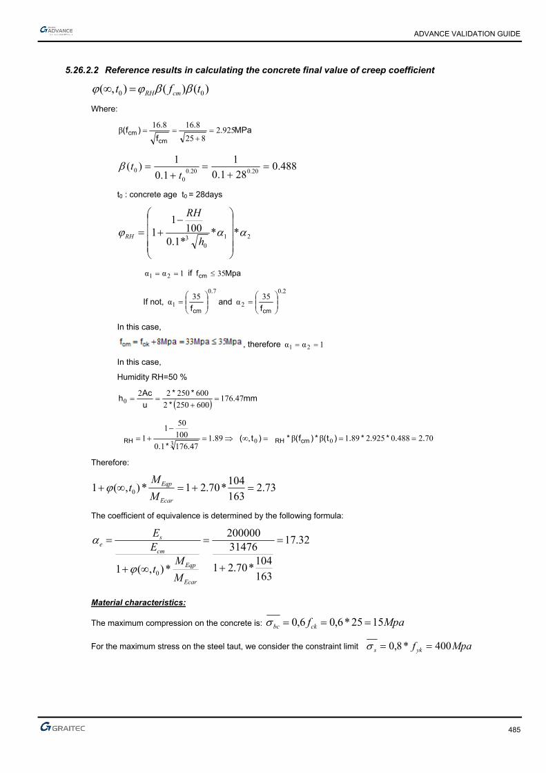
ADVANCE VALIDATION GUIDE
485
5.26.2.2 Reference results in calculating the concrete final value of creep coefficient
)()(),( 00 tft cmRH
Where:
MPa..
f
.)f(
cmcm 9252
825
816816β
488.0281.0
1
1.0
1)(
20.020.00
0
t
t
t0 : concrete age t0 = 28days
21
03
***1.0100
11
h
RH
RH
1αα 21 if Mpafcm 35
If not, 70
135
α.
cmf
and
20
235
α.
cmf
In this case,
, therefore 1αα 21
In this case,
Humidity RH=50 %
mm.*
**
u
Ach 47176
6002502
600250220
70248809252891ββ8914717610
100
501
1 003..*.*.)t(*)f(*)t,(.
.*.cmRHRH
Therefore:
73.2163
104*70.21*),(1 0
Ecar
Eqp
M
Mt
The coefficient of equivalence is determined by the following formula:
32.17
163
104*70.21
31476200000
*),(1 0
Ecar
Eqp
cm
se
M
Mt
EE
Material characteristics:
The maximum compression on the concrete is: Mpafckbc 1525*6,06,0
For the maximum stress on the steel taut, we consider the constraint limit Mpaf yks 400*8,0

ADVANCE VALIDATION GUIDE
486
Neutral axis position calculation:
The position of the neutral axis must be determined by calculating 1 (position corresponding to the state of
maximum stress on the concrete and reinforcement):
394.040015*32.17
15*32.17
*
*1
sce
ce
Moment resistance calculation:
Knowing the 1 value, it can be determined the moment resistance of the concrete section, using the following
formulas:
204051903940α11 ..*.d*x m
MNm..
.**.*.*.)x
d(**x*b*M cwrb 17303
2040519015204025050
3σ
2
1 11
Where:
Utile height : d = h – (0.06h + ebz) = 0.519m
The moment resistance Mrb = 173KNm
Because kNmMkNmM rbEcq 17394.162 the supposition of having no compressed reinforcement is
correct.
Calculation of reinforcement area with max constraint on steel and concrete
The reinforcement area is calculated using the SLS load combination
Neutral axis position: 394,01
Lever arm: m..
*.*dzc 45103
394015190
3
α1 1
Reinforcement section: ²03.9400*451.0
163.0
*,1 cmz
MA
sc
sersers
Reference solution for minimal reinforcement area
The minimum percentage for a rectangular beam in pure bending is:
db
dbf
f
MaxA
w
wyk
effct
s
**0013.0
***26.0 ,
min,
According to: EC2 Part 1,1 EN 1992-1-1-2002 Chapter 9.2.1.1(1); Note 2
Where:
MPaff ctmeffct 56.2, from cracking conditions
Therefore:
²73.1²10*69.1519.0*25.0*0013.0
²10*73.1519.0*25.0*500
56.226.0
max4
4
min, cmm
mAs

ADVANCE VALIDATION GUIDE
487
Finite elements modeling
■ Linear element: S beam,
■ 11 nodes,
■ 1 linear element.
ULS and SLS load combinations (kNm)
Simply supported beam subjected to bending
SLS (reference value: 162.94kNm)
Theoretical reinforcement area(cm2)
(reference value: 9.03cm2)
Minimum reinforcement area(cm2)
(reference value: 1.73cm2)

ADVANCE VALIDATION GUIDE
488
5.26.2.3 Reference results
Result name Result description Reference value
My,SLS My corresponding to the 102 combination (SLS) [kNm] 162.94 kNm
Az Theoretical reinforcement area [cm2] 9.03 cm2
Amin Minimum reinforcement area [cm2] 1.73 cm2
5.26.3 Calculated results
Result name Result description Value Error
My My USL -162.936 kN*m 0.0001 %
Az Az -9.02822 cm² -0.0000 %
Amin Amin -1.73058 cm² -0.0001 %

ADVANCE VALIDATION GUIDE
489
5.27 EC2 Test 14: Verifying a rectangular concrete beam subjected to a uniformly distributed load, with compressed reinforcement- Bilinear stress-strain diagram (Class XD1)
Test ID: 4987
Test status: Passed
5.27.1 Description
Simple Bending Design for Service State Limit - Verifies the adequacy of a rectangular cross section made from concrete C25/30 to resist simple bending.
During this test, the determination of stresses is made along with the determination of the longitudinal reinforcement and the verification of the minimum reinforcement percentage.
The verification of the bending stresses at service limit state is performed.
5.27.2 Background
Simple Bending Design for Service State Limit
Verifies the adequacy of a rectangular cross section made from concrete C25/30 to resist simple bending. During this test, the calculation of stresses is made along with the calculation of the longitudinal reinforcement and the verification of the minimum reinforcement percentage.
5.27.2.1 Model description
■ Reference: Guide de validation Eurocode 2 EN 1992-1-1-2002;
■ Analysis type: static linear (plane problem);
■ Element type: linear.
The following load cases and load combination are used:
■ Linear loads:
Loadings from the structure: G = 50 kN/m + dead load,
Exploitation loadings (category A): Q = 60kN/m,
■ Punctual loads
G=30kN
Q=25kN
3,02
Characteristic combination of actions: CCQ = 1.0 x G + 1.0 x Q
Quasi-permanent combination of actions: CQP = 1.0 x G + 0.3 x Q
Simply supported beam
ADVANCE VALIDATION GUIDE
490
Units
Metric System
Geometry
Below are described the beam cross section characteristics:
■ Height: h = 0.80 m,
■ Width: b = 0.40 m,
■ Length: L = 6.30 m,
■ Section area: A = 0.320 m2 ,
■ Concrete cover: c=4.5cm
■ Effective height: d=h-(0.6*h+ebz)=0.707m; d’=ebz=0.045m
Materials properties
Rectangular solid concrete C25/30 and S500A reinforcement steel is used. The following characteristics are used in relation to this material:
■ Exposure class XD1
■ Concrete density: 25kN/m3
■ Stress-strain law for reinforcement: Bilinear stress-strain diagram
■ The concrete age t0=28 days
■ Humidity RH=50%
Boundary conditions
The boundary conditions are described below:
■ Outer:
► Support at start point (x=0) restrained in translation along X, Y and Z,
► Support at end point (x = 5.80) restrained in translation along Y, Z and restrained in rotation along X.
■ Inner: None.
Loading
The beam is subjected to the following load combinations:
■ Dead load:
0.40*0.80*25 = 8kN/ml
■ Load combinations:
Characteristic combination of actions:
CCQ = 1.0 x G + 1.0 x Q=8+50+60=118kN/ml
Quasi-permanent combination of actions:
CQP = 1.0 x G + 0.3 x Q=8+50+0.3*60=76kN/ml
■ Load calculations:
mkNM cqser .05.672
8
²3.6*60508
4
3.6*2530,
mkNM qpser .11.436
8
²3.660*3.0508
4
3.6*25*3.030,

ADVANCE VALIDATION GUIDE
491
5.27.2.2 Reference results in calculating the concrete final value of creep coefficient
)()(),( 00 tft cmRH
Where:
MPaf
fcm
cm 92.2825
8.168.16)(
488.0281.0
1
1.0
1)(
20.020.00
0
t
t
t0 : concrete age t0=28days
21
03
***1.0100
11
h
RH
RH
121 if Mpafcm 35
If not
7.0
1
35
cmf and
2.0
2
35
cmf
In this case therefore
121
In this case:
Humidity RH=50 %
mmu
Ach 267
800400*2
800*400*220
54.2488.0*92.2*78.1)(*)(*),(78.1267*1.0
100
501
1 003
tft cmRHRH
Calculating the equivalence coefficient:
The coefficient of equivalence is determined by the following formula:
Ecar
Eqp
cm
se
M
Mt
EE
*),(1 0
Where:
MPaf
E ckcm 31476
10
825*22
10
8*22
3.03.0
MPaEs 200000

ADVANCE VALIDATION GUIDE
492
65.2672
435*54.21*),(1 0
Ecar
Eqp
M
Mt
82.16
672
435*54.21
31476200000
*),(1 0
Ecar
Eqp
cm
se
M
Mt
EE
Material characteristics:
The maximum compression on the concrete is: Mpafckbc 1515*6,0*6,0
For the maximum stress on the steel taut, we consider the constraint limit Mpaf yks 400*8,0
Neutral axis position calculation:
The position of the neutral axis must be determined by calculating (position corresponding to the state of maximum stress on the concrete and reinforcement):
387.040018*82.16
15*82.16
*
*1
sce
ce
Moment resistance calculation:
Knowing the 1α value, it can be determined the moment resistance of the concrete section, using the following
formulas:
273.0707.0*387.0*11 dx m
MNmx
dxbM cwrb 505.03
273.0707.0*15*273.0*4.0*5.0)
3(****
2
1 11
Where:
Utile height : d = h – (0.06h + ebz) = 0.707m
The moment resistance Mrb = 505KNm
Because kNmMkNmM rbEcq 505672 , the supposition of having no compressed reinforcement is
incorrect.
The calculation of the tension reinforcement theoretical section A1
mx
dzc 616.03
273.0707.0
31
²51.20400*616.0
505.0
*1 cmz
MA
sc
rb

ADVANCE VALIDATION GUIDE
493
Stress calculation for steel reinforcement σsc:
064.0707.0
045.0'' d
d
MPacesc 78.210387.0
067.0387.0*15*82.16
'**
1
1
Calculation of the steel compressed reinforcement A’:
²96.1178.210*)045.0707.0(
505.0672.0
*)'(' cm
dd
MMA
sc
rbser
Calculation of the steel tensioned reinforcement A2:
²30.6400
78.210*96.11'*2 cmAA
s
sc
Calculation of the steel reinforcement :
²81.2630.651.2021 cmAAA
Reference solution for minimal reinforcement area
The minimum percentage for a rectangular beam in pure bending is:
db
dbf
f
MaxA
w
wyk
effct
s
**0013.0
***26.0 ,
min,
According to: EC2 Part 1,1 EN 1992-1-1-2002 Chapter 9.2.1.1(1); Note 2
Where:
MPaff ctmeffct 56.2, from cracking conditions
Therefore:
²76.3²10*68.3707.0*40.0*0013.0
²10*76.3707.0*40.0*500
56.2*26.0
max4
4
min, cmm
mAs
Finite elements modeling
■ Linear element: S beam,
■ 7 nodes,
■ 1 linear element.

ADVANCE VALIDATION GUIDE
494
ULS and SLS load combinations (kNm)
Simply supported beam subjected to bending
SLS (reference value: 672kNm)
Theoretical reinforcement area (cm2)
(reference value: As=26.81cm2; A’=11.96cm2)
Minimum reinforcement area (cm2)
(reference value: 3.76cm2)
5.27.2.3 Reference results
Result name Result description Reference value
My,SLS My corresponding to the 102 combination (SLS) [kNm] 672 kNm
Az Theoretical reinforcement area [cm2] 26.81 cm2
Amin Minimum reinforcement area [cm2] 3.77 cm2
5.27.3 Calculated results
Result name Result description Value Error
My My SLS -672.032 kN*m -0.0001 %
Az Az -26.8086 cm² -0.0001 %
Amin Amin -3.77193 cm² -0.0001 %

ADVANCE VALIDATION GUIDE
495
5.28 EC2 Test 18: Verifying a rectangular concrete beam subjected to a uniformly distributed load, with compressed reinforcement - Bilinear stress-strain diagram (Class XD1)
Test ID: 5011
Test status: Passed
5.28.1 Description
Simple Bending Design for Serviceability State Limit - Verifies the adequacy of a rectangular cross section made from concrete C25/30 to resist simple bending.
During this test, the determination of stresses is made along with the determination of compressing stresses in concrete section and compressing stresses in the steel reinforcement section.
5.28.2 Background
Simple Bending Design for Serviceability State Limit
Verifies the adequacy of a rectangular cross section made from concrete C25/30 to resist simple bending. During this test, the calculation of stresses is made along with the calculation of compressing stresses in concrete section σc and compressing stresses in the steel reinforcement section σs.
5.28.2.1 Model description
■ Reference: Guide de validation Eurocode 2 EN 1992-1-1-2002;
■ Analysis type: static linear (plane problem);
■ Element type: linear.
The following load cases and load combination are used:
■ Loadings from the structure: G = 37.5 kN/m (including the dead load),
■ Exploitation loadings (category A): Q = 37.5 kN/m,
■ Structural class: S4
■ Reinforcement steel ductility: Class A
■ For the stress calculation the French annexes was used
The objective is to verify:
■ The stresses results
■ The compressing stresses in concrete section σc
■ The compressing stresses in the steel reinforcement section σs.
Simply supported beam
Units
Metric System

ADVANCE VALIDATION GUIDE
496
Geometry
Below are described the beam cross section characteristics:
■ Height: h = 0.80 m,
■ Width: b = 0.35 m,
■ Length: L = 8.00 m,
■ Section area: A = 0.28 m2 ,
■ Concrete cover: c=4 cm
■ Effective height: d=72cm;
Materials properties
Rectangular solid concrete C25/30 is used. The following characteristics are used in relation to this material:
■ Exposure class XD1
■ Stress-strain law for reinforcement: Bilinear stress-strain diagram
■ The concrete age t0=28 days
■ Humidity RH=50%
■ Characteristic compressive cylinder strength of concrete at 28 days: Mpafck 25
■ Characteristic yield strength of reinforcement: Mpafyk 500
■ ²cm.Ast 7037 for 3 HA20
■ ²cm.Asc 286 for 2 HA10
Boundary conditions
The boundary conditions are described below:
■ Outer:
► Support at start point (x=0) restrained in translation along X, Y and Z,
► Support at end point (x = 8) restrained in translation along Y and Z
■ Inner: None.
Loading
The beam is subjected to the following load combinations:
■ Load combinations:
► Characteristic combination of actions:
CCQ = 1.0*G+1.0*Q =75 kN/ml
■ Load calculations:
► M0Ed = 855 kNm
► Mcar = 600 kNm
► Mqp = 390 kNm

ADVANCE VALIDATION GUIDE
497
5.28.2.2 Reference results in calculating the concrete final value of creep coefficient
)()(),( 00 tft cmRH
Where:
MPaf
fcm
cm 92.2825
8.168.16)(
488.0281.0
1
1.0
1)(
20.020.00
0
t
t
t0 : concrete age t0=28days
21
03
***1.0100
11
h
RH
RH
if
If not,
7.0
1
35
cmf and
2.0
2
35
cmf
In this case,
, therefore 121
In this case,
Humidity RH=50 %
mmu
Ach 48.243
800350*2
800*350*220
56.2488.0*92.2*80.1)(*)(*),(80.148.243*1.0
100
501
1 003
tft cmRHRH
The coefficient of equivalence is determined by the following formula:
Ecar
Eqp
cm
se
M
Mt
EE
*),(1 0

ADVANCE VALIDATION GUIDE
498
Where:
MPaf
E ckcm 31476
10
825*22
10
8*22
3.03.0
MPaEs 200000
664.2600
390*56.21*),(1 0
Ecar
Eqp
M
Mt
90.16
664.2
31476200000
*),(1 0
Ecar
Eqp
cm
se
M
Mt
EE
Material characteristics:
The maximum compression on the concrete is: Mpafckbc 1525*6,06,0
For the maximum stress on the steel taut, we consider the constraint limit Mpaf yks 320*8,0
Neutral axis position calculation:
Neutral axis equation: 0αα2
1111 )'dx(**A)xd(**A²x*b* escestw
cm,).*.*(*.**)²..(*².)..(*.
b
)A'*dA*d(**b*)²AA(*²)AA(*x scstewscstescste
413435
286470377290163522867037901628670379016
α2αα1
Calculating the second moment:
443
11
31
0147201472097445349016286453472901670373
413435
αα3
m.cm)².(*.*,)²,(.*,,*
)²'dx(**A)²xd(**Ax*b
I escestw
Stresses calculation:
MpaMpaxI
Mc
serc 12143441,0*
01472,0
600,0* 1
MpaMpax
xdscest 400259
3441,0
3441,072,0*14*90.16**
1
1
Finite elements modeling
■ Linear element: S beam,
■ 9 nodes,
■ 1 linear element.
ADVANCE VALIDATION GUIDE
499
SLS load combinations (kNm) and stresses (MPa)
Simply supported beam subjected to bending
SLS (reference value: Mscq=600kNm)
Compressing stresses in concrete section σc
(reference value: σc =14MPa )
Compressing stresses in the steel reinforcement section σs
(reference value: σs=260.15MPa)
5.28.2.3 Reference results
Result name Result description Reference value
My,SLS My corresponding to the 104 combination (SLS) [kNm] 600 kNm
σc Compressing stresses in concrete section σc (MPa) 14 MPa
σs Compressing stresses in the steel reinforcement section σs (MPa) 260.15 MPa
5.28.3 Calculated results
Result name Result description Value Error
My My SLS -600 kN*m 0.0000 %
Sc CQ Sc CQ 14.122 MPa 0.0142 %
Ss CQ Ss CQ -260.116 MPa 0.0014 %
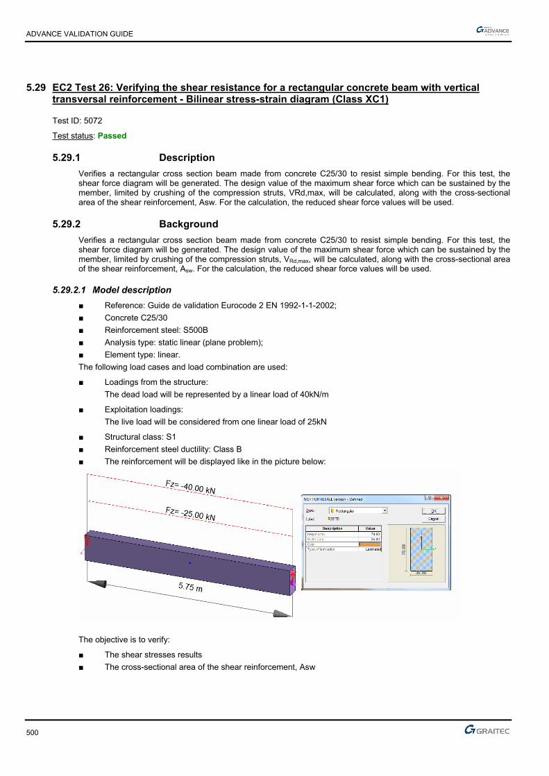
ADVANCE VALIDATION GUIDE
500
5.29 EC2 Test 26: Verifying the shear resistance for a rectangular concrete beam with vertical transversal reinforcement - Bilinear stress-strain diagram (Class XC1)
Test ID: 5072
Test status: Passed
5.29.1 Description
Verifies a rectangular cross section beam made from concrete C25/30 to resist simple bending. For this test, the shear force diagram will be generated. The design value of the maximum shear force which can be sustained by the member, limited by crushing of the compression struts, VRd,max, will be calculated, along with the cross-sectional area of the shear reinforcement, Asw. For the calculation, the reduced shear force values will be used.
5.29.2 Background
Verifies a rectangular cross section beam made from concrete C25/30 to resist simple bending. For this test, the shear force diagram will be generated. The design value of the maximum shear force which can be sustained by the member, limited by crushing of the compression struts, VRd,max, will be calculated, along with the cross-sectional area of the shear reinforcement, Asw. For the calculation, the reduced shear force values will be used.
5.29.2.1 Model description
■ Reference: Guide de validation Eurocode 2 EN 1992-1-1-2002;
■ Concrete C25/30
■ Reinforcement steel: S500B
■ Analysis type: static linear (plane problem);
■ Element type: linear.
The following load cases and load combination are used:
■ Loadings from the structure:
The dead load will be represented by a linear load of 40kN/m
■ Exploitation loadings:
The live load will be considered from one linear load of 25kN
■ Structural class: S1
■ Reinforcement steel ductility: Class B
■ The reinforcement will be displayed like in the picture below:
The objective is to verify:
■ The shear stresses results
■ The cross-sectional area of the shear reinforcement, Asw
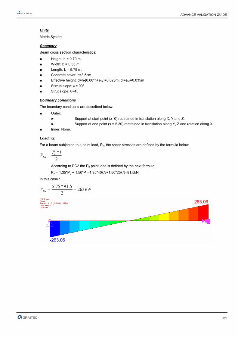
ADVANCE VALIDATION GUIDE
501
Units
Metric System
Geometry
Beam cross section characteristics:
■ Height: h = 0.70 m,
■ Width: b = 0.35 m,
■ Length: L = 5.75 m,
■ Concrete cover: c=3.5cm
■ Effective height: d=h-(0.06*h+ebz)=0.623m; d’=ehz=0.035m
■ Stirrup slope: = 90°
■ Strut slope: θ=45˚
Boundary conditions
The boundary conditions are described below:
■ Outer:
► Support at start point (x=0) restrained in translation along X, Y and Z,
► Support at end point (x = 5.30) restrained in translation along Y, Z and rotation along X
■ Inner: None.
Loading:
For a beam subjected to a point load, Pu, the shear stresses are defined by the formula below:
2
* lPV uEd
According to EC2 the Pu point load is defined by the next formula:
Pu = 1,35*Pg + 1,50*Pq=1.35*40kN+1.50*25kN=91.5kN
In this case :
KNVEd 2632
5.91*75.5
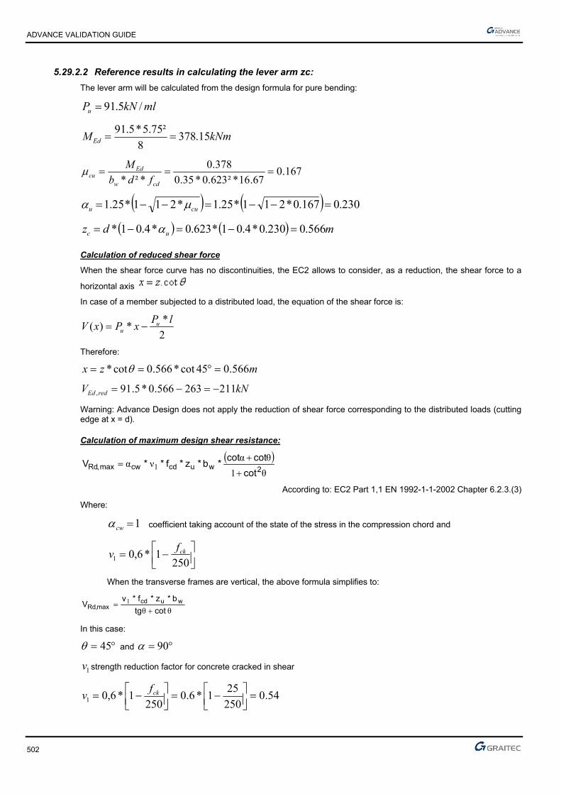
ADVANCE VALIDATION GUIDE
502
5.29.2.2 Reference results in calculating the lever arm zc:
The lever arm will be calculated from the design formula for pure bending:
mlkNPu /5.91
kNmMEd 15.3788
²75.5*5.91
167.067.16*²623.0*35.0
378.0
*²*
cdw
Edcu fdb
M
230.0167.0*211*25.1*211*25.1 cuu
mdz uc 566.0230.0*4.01*623.0*4.01*
Calculation of reduced shear force
When the shear force curve has no discontinuities, the EC2 allows to consider, as a reduction, the shear force to a
horizontal axis
In case of a member subjected to a distributed load, the equation of the shear force is:
2
**)(
lPxPxV u
u
Therefore:
mzx 566.045cot*566.0cot*
kNV redEd 211263566.0*5.91,
Warning: Advance Design does not apply the reduction of shear force corresponding to the distributed loads (cutting edge at x = d).
Calculation of maximum design shear resistance:
θ1
θανα 1 2wucdcwmax,Rd
cot
cotcot*b*z*f**V
According to: EC2 Part 1,1 EN 1992-1-1-2002 Chapter 6.2.3.(3)
Where:
1cw coefficient taking account of the state of the stress in the compression chord and
2501*6,01
ckfv
When the transverse frames are vertical, the above formula simplifies to:
θθ1
cottg
b*z*f*vV wucd
max,Rd
In this case:
45 and 90
1v strength reduction factor for concrete cracked in shear
54.0250
251*6.0
2501*6,01
ckfv

ADVANCE VALIDATION GUIDE
503
mdzu 56.0623.0*9.0*9.0
kNMNVRd 891891.02
35.0*566.0*67.16*54.0max,
kNVkNV RdEd 891236 max,
Calculation of transversal reinforcement:
Given the vertical transversal reinforcement ( = 90°), the following formula is used:
mlcmtg
fz
tgV
s
A
ywdu
Edsw /²67,8
15,1
500*566,0
45*211,0
*
*.
Finite elements modeling
■ Linear element: S beam,
■ 3 nodes,
■ 1 linear element.
Advance Design gives the following results for Atz (cm2/ml)
5.29.2.3 Reference results
Result name Result description Reference value
Fz Fz corresponding to the 101 combination (ULS) [kNm] 263 kN
At,z Theoretical reinforcement area [cm2/ml] 8.67 cm2/ml
5.29.3 Calculated results
Result name Result description Value Error
Fz Fz -263.062 kN -0.0002 %
Atz Atz 8.68636 cm² 0.0000 %

ADVANCE VALIDATION GUIDE
504
5.30 EC2 Test 27: Verifying the shear resistance for a rectangular concrete beam with vertical transversal reinforcement - Bilinear stress-strain diagram (Class XC1)
Test ID: 5076
Test status: Passed
5.30.1 Description
Verifies a rectangular cross section beam made from concrete C25/30 to resist simple bending. For this test, the shear force diagram is generated. The design value of the maximum shear force which can be sustained by the member, limited by crushing of the compression struts, VRd,max., will be calculated, along with the cross-sectional area of the shear reinforcement, Asw, and the theoretical reinforcement. For the calculation, the reduced shear force values will be used.
5.30.2 Background
Description: Verifies a rectangular cross section beam made from concrete C25/30 to resist simple bending. For this test, the shear force diagram is generated. The design value of the maximum shear force which can be sustained by the member, limited by crushing of the compression struts, VRd,max. will be calculated, along with the cross-sectional area of the shear reinforcement, Asw, and the theoretical reinforcement.
5.30.2.1 Model description
■ Reference: Guide de validation Eurocode 2 EN 1992-1-1-2002;
■ Concrete C25/30
■ Reinforcement steel: S500B
■ Analysis type: static linear (plane problem);
■ Element type: linear.
The following load cases and load combination are used:
■ Loadings from the structure:
The dead load will be represented by a linear load of 40kN/m
■ Exploitation loadings:
The live load will be considered from one linear load of 25kN
■ Structural class: S1
■ Reinforcement steel ductility: Class B
■ The reinforcement will be displayed like in the picture below:
The objective is to verify:
■ The shear stresses results
■ The theoretical reinforcement value

ADVANCE VALIDATION GUIDE
505
Units
Metric System
Geometry
Beam cross section characteristics:
■ Height: h = 0.70 m,
■ Width: b = 0.35 m,
■ Length: L = 5.75 m,
■ Concrete cover: c=3.5cm
■ Effective height: d=h-(0.06*h+ebz)=0.623m; d’=ehz=0.035m
■ Stirrup slope: = 90°
■ Strut slope: θ=45˚
Boundary conditions
The boundary conditions are described below:
■ Outer:
► Support at start point (x=0) restrained in translation along X, Y and Z,
► Support at end point (x = 5.30) restrained in translation along Y, Z and rotation along X
■ Inner: None.
Loading:
For a beam subjected to a point load, Pu, the shear stresses are defined by the formula below:
2
* lPV uEd
According to EC2 the Pu point load is defined by the next formula:
Pu = 1,35*Pg + 1,50*Pq=1.35*40kN+1.50*25kN=91.5kN
In this case :
KNVEd 2632
5.91*75.5

ADVANCE VALIDATION GUIDE
506
5.30.2.2 Reference results in calculating the lever arm zc:
The lever arm is calculated using the design formula for pure bending:
mlkNPu /5.91
kNmMEd 15.3788
²75.5*5.91
167.067.16*²623.0*35.0
378.0
*²*
cdw
Edcu fdb
M
230.0167.0*211*25.1*211*25.1 cuu
mdz uc 566.0230.0*4.01*623.0*4.01*
Calculation of reduced shear force
When the shear force curve has no discontinuities, the EC2 allows to consider, as a reduction, the shear force to a
horizontal axis cot.zx .
In the case of a member subjected to a distributed load, the equation of the shear force is:
2
**)(
lPxPxV u
u
Therefore:
mzx 566.045cot*566.0cot*
kNV redEd 211263566.0*5.91,
Warning: Advance Design does not apply the reduction of shear force corresponding to the distributed loads (cutting edge at x = d).
Calculation of maximum design shear resistance:
θ1
θανα 1 2wucdcwmax,Rd
cot
cotcot*b*z*f**V
According to: EC2 Part 1,1 EN 1992-1-1-2002 Chapter 6.2.3.(3)
Where:
1cw coefficient taking account of the state of the stress in the compression chord and
2501*6,01
ckfv
When the transverse frames are vertical, the above formula simplifies to:
cot
***1max,
tg
bzfvV wucdRd
In this case:
45 and 90
1v strength reduction factor for concrete cracked in shear
54.0250
251*6.0
2501*6,01
ckfv

ADVANCE VALIDATION GUIDE
507
mdzu 56.0623.0*9.0*9.0
kNMNVRd 891891.02
35.0*566.0*67.16*54.0max,
kNVkNV RdEd 891236 max,
Calculation of transversal reinforcement:
Given the vertical transversal reinforcement ( = 90°), the transverse reinforcement is calculated using the following formula:
mlcmtg
fz
tgV
s
A
ywdu
Edsw /²67,8
15,1
500*566,0
45*211,0
*
*.
Calculation of theoretical reinforcement value:
The French national annex indicates the formula:
sin**min, wwsw bs
A
With:
4min, 1015.7
500
20*08,0*08,0 yk
ckw f
f
mlcmbs
Aww
sw /²43.190sin*2.0*10*15.7sin** 4min,
Finite elements modeling
■ Linear element: S beam,
■ 3 nodes,
■ 1 linear element.
Advance Design gives the following results for At,min,z (cm2/ml)

ADVANCE VALIDATION GUIDE
508
5.30.2.3 Reference results
Result name Result description Reference value
Fz Fz corresponding to the 101 combination (ULS) [kNm] 263 kN
At,min,z Theoretical reinforcement area [cm2/ml] 1.43 cm2/ml
5.30.3 Calculated results
Result name Result description Value Error
Fz Fz -168.937 kN -0.0003 %
Atminz Atmin,z 1.43108 cm² 0.0002 %

ADVANCE VALIDATION GUIDE
509
5.31 EC2 Test29: Verifying the shear resistance for a T concrete beam with inclined transversal reinforcement - Inclined stress-strain diagram (Class XC1)
Test ID: 5092
Test status: Passed
5.31.1 Description
Verifies a T cross section beam made from concrete C35/40 to resist simple bending. For this test, the shear force diagram and the moment diagram will be generated. The design value of the maximum shear force which can be sustained by the member, limited by crushing of the compression struts, VRd,max., will be determined, along with the cross-sectional area of the shear reinforcement, Asw, calculation. The test will not use the reduced shear force value.
The beam model was provided by Bouygues.
5.31.2 Background
Verifies a T cross section beam made from concrete C35/40 to resist simple bending. For this test, the shear force diagram and the moment diagram will be generated. The design value of the maximum shear force which can be sustained by the member, limited by crushing of the compression struts, VRd,max, will be determined, along with the cross-sectional area of the shear reinforcement, Asw. The test will not use the reduced shear force value.
The beam model was provided by Bouygues.
5.31.2.1 Model description
■ Reference: Guide de validation Eurocode 2 EN 1992-1-1-2002;
■ Concrete: C35/40
■ Reinforcement steel: S500B
■ Analysis type: static linear (plane problem);
■ Element type: linear.
The following load cases and load combination are used:
■ Loadings from the structure:
The dead load will be represented by two linear loads of 22.63kN/m and 47.38kN/m
■ Exploitation loadings:
The live load will be considered from one linear load of 80.00kN/m
■ Structural class: S3
■ Reinforcement steel ductility: Class B
■ Exposure class: XC1
■ Characteristic compressive cylinder strength of concrete at 28 days:
■ Partial factor for concrete:

ADVANCE VALIDATION GUIDE
510
■ Relative humidity: RH=50%
■ Concrete age: t0=28days
■ Design value of concrete compressive strength: fcd=23 MPa
■ Secant modulus of elasticity of concrete: Ecm=34000 MPa
■ Concrete density:
■ Mean value of axial tensile strength of concrete: fctm=3.2 MPa
■ Final value of creep coefficient:
■ Characteristic yield strength of reinforcement:
■ Steel ductility: Class B
■ K coefficient: k=1.08
■ Design yield strength of reinforcement:
■ Design value of modulus of elasticity of reinforcing steel: Es=200000MPa
■ Steel density:
■ Characteristic strain of reinforcement or prestressing steel at maximum load:
■ Strain of reinforcement or prestressing steel at maximum load:
■ Slenderness ratio: 80.0
The objective is to verify:
■ The of shear stresses results
■ The longitudinal reinforcement corresponding to a 5cm concrete cover
■ The transverse reinforcement corresponding to a 2.7cm concrete cover
Units
Metric System
Geometry
Below are described the beam cross section characteristics:
■ Length: L = 10.00 m,
■ Stirrup slope: = 90°
■ Strut slope: θ=29.74˚
Boundary conditions
The boundary conditions are described below:
■ Outer:
► Support at start point (x=0) restrained in translation along X, Y and Z,
► Support at end point (x = 10.00) restrained in translation along Y, Z and rotation along X
■ Inner: None.

ADVANCE VALIDATION GUIDE
511
Loading:
Note: In Advance Design, the shear reduction is not taken into account. These are the values corresponding to an unreduced shear that will be used for further calculations.
5.31.2.2 Reference results in calculating the longitudinal reinforcement
For a 5 cm concrete cover and dinit=1.125m, the reference value will be 108.3 cm2:
For a 2.7 cm concrete cover and dinit=1.148m, the reference value will be 105.7 cm2:
5.31.2.3 Reference results in calculating the transversal reinforcement
ywdu
Edsw
fz
tgV
s
A
*
*.
Where:
mdzu 0125.1125.1*9.0*9.0
74.2975.1cot
90
mlcmtg
fz
tgV
s
A
ywdu
Edsw /²50.19
15,1
500*0125.1
74.29*502.1
*
*.
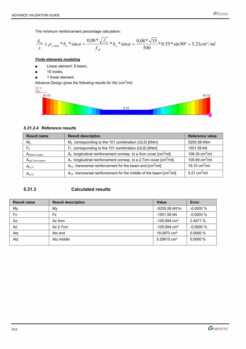
ADVANCE VALIDATION GUIDE
512
The minimum reinforcement percentage calculation:
mlcmbf
fb
s
Aw
yk
ckww
sw /²21.590sin*55.0*500
35*08,0sin**
*08,0sin**min,
Finite elements modeling
■ Linear element: S beam,
■ 15 nodes,
■ 1 linear element.
Advance Design gives the following results for Atz (cm2/ml)
5.31.2.4 Reference results
Result name Result description Reference value
My My corresponding to the 101 combination (ULS) [kNm] 5255.58 kNm
Fz Fz corresponding to the 101 combination (ULS) [kNm] 1501.59 kN
Az(5cm cover) Az longitudinal reinforcement corresp. to a 5cm cover [cm2/ml] 108.30 cm2/ml
Az(2.7cm cover) Az longitudinal reinforcement corresp. to a 2.7cm cover [cm2/ml] 105.69 cm2/ml
At,z,1 At,z transversal reinforcement for the beam end [cm2/ml] 19.10 cm2/ml
At,z,2 At,z transversal reinforcement for the middle of the beam [cm2/ml] 5.21 cm2/ml
5.31.3 Calculated results
Result name Result description Value Error
My My -5255.58 kN*m -0.0000 %
Fz Fz -1501.59 kN -0.0003 %
Az Az 5cm -105.694 cm² 2.4071 %
Az Az 2.7cm -105.694 cm² -0.0000 %
Atz Atz end 19.0973 cm² 0.0000 %
Atz Atz middle 5.20615 cm² 0.0000 %

ADVANCE VALIDATION GUIDE
513
5.32 EC2 Test30: Verifying the shear resistance for a T concrete beam with inclined transversal reinforcement - Bilinear stress-strain diagram (Class XC1)
Test ID: 5098
Test status: Passed
5.32.1 Description
Verifies a T cross section beam made from concrete C30/37 to resist simple bending. For this test, the shear force diagram and the moment diagram will be generated. The design value of the maximum shear force which can be sustained by the member, limited by crushing of the compression struts, VRd,max, will be determined, along with the cross-sectional area of the shear reinforcement, Asw. The test will not use the reduced shear force value.
The beam model was provided by Bouygues.
5.32.2 Background
Verifies a T cross section beam made from concrete C30/37 to resist simple bending. For this test, the shear force diagram and the moment diagram will be generated. The design value of the maximum shear force which can be sustained by the member, limited by crushing of the compression struts, VRd,max, will be determined, along with the cross-sectional area of the shear reinforcement, Asw. The test will not use the reduced shear force value.
The beam model was provided by Bouygues.
5.32.2.1 Model description
■ Reference: Guide de validation Eurocode 2 EN 1992-1-1-2002;
■ Concrete: C35/40
■ Reinforcement steel: S500B
■ Analysis type: static linear (plane problem);
■ Element type: linear.
The following load cases and load combination are used:
■ Loadings from the structure:
The dead load will be represented by two linear loads of 23.50kN/m and 43.50kN/m
■ Exploitation loadings:
The live load will be considered from one linear load of 25.00kN/m
■ Structural class: S3
■ Reinforcement steel ductility: Class B
■ Exposure class: XC1
■ Characteristic compressive cylinder strength of concrete at 28 days:
■ Partial factor for concrete:

ADVANCE VALIDATION GUIDE
514
■ Relative humidity: RH=50%
■ Concrete age: t0=28days
■ Design value of concrete compressive strength: fcd=20 MPa
■ Secant modulus of elasticity of concrete: Ecm=33000 MPa
■ Concrete density:
■ Mean value of axial tensile strength of concrete: fctm=2.9 MPa
■ Final value of creep coefficient:
■ Characteristic yield strength of reinforcement:
■ Steel ductility: Class B
■ K coefficient: k=1.08
■ Design yield strength of reinforcement:
■ Design value of modulus of elasticity of reinforcing steel: Es=200000MPa
■ Steel density:
■ Characteristic strain of reinforcement or prestressing steel at maximum load:
■ Strain of reinforcement or prestressing steel at maximum load:
■ Slenderness ratio:
The objective is to verify:
■ The shear stresses results
■ The longitudinal reinforcement corresponding to a 6.4cm concrete cover
■ The transverse reinforcement corresponding to a 4.3cm concrete cover
Units
Metric System
Geometry
Below are described the beam cross section characteristics:
■ Length: L = 8.10 m,
■ Stirrup slope: = 90°
■ Strut slope: θ=22.00˚
Boundary conditions
The boundary conditions are described below:
■ Outer:
► Support at start point (x = 0) restrained in translation along X, Y and Z,
► Support at end point (x = 10.00) restrained in translation along Y, Z and rotation along X
■ Inner: None.

ADVANCE VALIDATION GUIDE
515
Loading:
Note: In Advance Design, the shear reduction is not taken into account. These are the values corresponding to an unreduced shear that will be used for further calculations.
5.32.2.2 Reference results in calculating the longitudinal reinforcement
For a 6.4 cm concrete cover and dinit=0.50m, the reference value will be 57.1 cm2:
For a 4.3 cm concrete cover and dinit=0.521, the reference value will be 54.3 cm2:
5.32.2.3 Reference results in calculating the transversal reinforcement
ywdu
Edsw
fz
tgV
s
A
*
*.
Where:
mdzu 469.0521.0*9.0*9.0
225.2cot
90
mlcmtg
fz
tgV
s
A
ywdu
Edsw /²67.11
15,1
500*469.0
22*589.0
*
*.
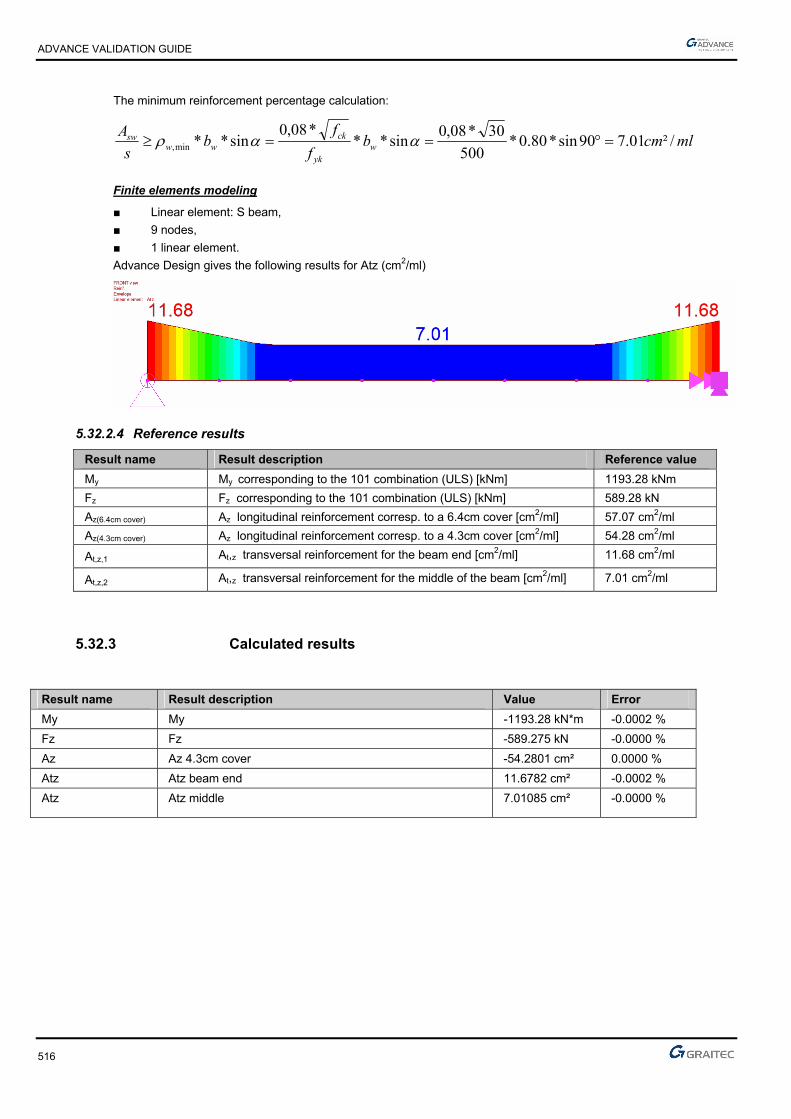
ADVANCE VALIDATION GUIDE
516
The minimum reinforcement percentage calculation:
mlcmbf
fb
s
Aw
yk
ckww
sw /²01.790sin*80.0*500
30*08,0sin**
*08,0sin**min,
Finite elements modeling
■ Linear element: S beam,
■ 9 nodes,
■ 1 linear element.
Advance Design gives the following results for Atz (cm2/ml)
5.32.2.4 Reference results
Result name Result description Reference value
My My corresponding to the 101 combination (ULS) [kNm] 1193.28 kNm
Fz Fz corresponding to the 101 combination (ULS) [kNm] 589.28 kN
Az(6.4cm cover) Az longitudinal reinforcement corresp. to a 6.4cm cover [cm2/ml] 57.07 cm2/ml
Az(4.3cm cover) Az longitudinal reinforcement corresp. to a 4.3cm cover [cm2/ml] 54.28 cm2/ml
At,z,1 At,z transversal reinforcement for the beam end [cm2/ml] 11.68 cm2/ml
At,z,2 At,z transversal reinforcement for the middle of the beam [cm2/ml] 7.01 cm2/ml
5.32.3 Calculated results
Result name Result description Value Error
My My -1193.28 kN*m -0.0002 %
Fz Fz -589.275 kN -0.0000 %
Az Az 4.3cm cover -54.2801 cm² 0.0000 %
Atz Atz beam end 11.6782 cm² -0.0002 %
Atz Atz middle 7.01085 cm² -0.0000 %

ADVANCE VALIDATION GUIDE
517
5.33 EC2 Test 25: Verifying the shear resistance for a rectangular concrete beam with inclined transversal reinforcement - Bilinear stress-strain diagram (Class XC1)
Test ID: 5065
Test status: Passed
5.33.1 Description
Verifies the shear resistance for a rectangular concrete beam C20/25 with inclined transversal reinforcement - Bilinear stress-strain diagram (Class XC1).
For this test, the shear force diagram will be generated. The design value of the maximum shear force which can be sustained by the member, limited by crushing of the compression struts (VRd,max) is calculated, along with the cross-sectional area of the shear reinforcement (Asw).
5.33.2 Background
Verifies a rectangular cross section beam made from concrete C20/25 to resist simple bending. For this test, the shear force diagram will be generated. The design value of the maximum shear force which can be sustained by the member, limited by crushing of the compression struts (VRd,max) is calculated, along with the cross-sectional area of the shear reinforcement (Asw).
5.33.2.1 Model description
■ Reference: Guide de validation Eurocode 2 EN 1992-1-1-2002;
■ Concrete C20/25
■ Reinforcement steel: S500B
■ Analysis type: static linear (plane problem);
■ Element type: linear.
The following load cases and load combination are used:
■ Loadings from the structure:
The dead load will be represented by a punctual load of 105kN
■ Exploitation loadings:
The live load will be considered from one point load of 95kN
■ Structural class: S1
■ Reinforcement steel ductility: Class B
■ The reinforcement will be displayed like in the picture below:

ADVANCE VALIDATION GUIDE
518
The objective is to verify:
■ The shear stresses results
■ The cross-sectional area of the shear reinforcement, Asw
Units
Metric System
Geometry
Below are described the beam cross section characteristics:
■ Height: h = 0.50 m,
■ Width: b = 0.20 m,
■ Length: L = 3.00 m,
■ Concrete cover: c=3.5cm
■ Effective height: d=h-(0.06*h+ebz)=0.435m; d’=ehz=0.035m
■ Stirrup slope: = 45°
■ Strut slope: θ=30˚
Boundary conditions
The boundary conditions are described below:
■ Outer:
► Support at start point (x=0) restrained in translation along X, Y and Z,
► Support at end point (x = 5.30) restrained in translation along Y, Z and rotation along X
■ Inner: None.
Loading:
For a beam subjected to a point load, Pu, the shear stresses are defined by the formula below:
l
aPV uEd 1
According to EC2 the Pu point load is defined by the next formula:
Pu = 1,35*Pg + 1,50*Pq=1.35*105kN=1.50*95kN=284.25kN
In this case (a=1m; l=3m):
KNVEd 5,1893
11*25,284
Note: In Advance Design, the shear reduction is not taken into account. These are the values corresponding to an unreduced shear that will be used for further calculations.

ADVANCE VALIDATION GUIDE
519
5.33.2.2 Reference results in calculating the maximum design shear resistance
According to: EC2 Part 1,1 EN 1992-1-1-2002 Chapter 6.2.3.(3)
Where:
1cw coefficient taking account of the state of the stress in the compression chord and
2501*6,01
ckfv
In this case,
30 and 45
1v strength reduction factor for concrete cracked in shear
55.0250
201*6.0
2501*6,01
ckfv
mdzu 392.0435.0*9.0*9.0
3940
301
3420039203313540 .
cot
0cot5cot*.*.*.*.V
2max,Rd
MNVMNV RdEd 394.01895.0 max,
Calculation of transverse reinforcement:
The transverse reinforcement is calculated using the following formula:
mlcmfz
V
s
A
ywdu
Edsw /²76.545sin*)45cot30(cot*78.434*392.0
18950.0
sin*)cot(cot**
Beyond the point load, the shear force is constant and equal to Rb, therefore,
it also calculates the required reinforcement area to the right side of the beam:
mlcms
Asw /²88.245sin*)45cot30(cot*78.434*392.0
09475.0
Finite elements modeling
■ Linear element: S beam,
■ 3 nodes,
■ 1 linear element.
Advance Design gives the following results for Atz (cm2/ml)

ADVANCE VALIDATION GUIDE
520
5.33.2.3 Reference results
Result name Result description Reference value
Fz,1 Fz corresponding to the 101 combination (ULS) x=1.0m [kN] 189.5 kN
Fz,2 Fz corresponding to the 101 combination (ULS) x=1.01m [kN] 94.75 kN
At,z,1 Theoretical reinforcement area at x=1.0m [cm2/ml] 5.76 cm2/ml
At,z,2 Theoretical reinforcement area at x=1.01m [cm2/ml] 2.88 cm2/ml
5.33.3 Calculated results
Result name Result description Value Error
Fz Fz,1 -189.5 kN -0.0000 %
Fz Fz,2 94.75 kN 0.0000 %
Atz Atz,1 5.76277 cm² 0.0001 %
Atz Atz,2 2.88139 cm² -0.0001 %

ADVANCE VALIDATION GUIDE
521
5.34 EC2 Test 46 I: Verifying a square concrete beam subjected to a normal force of traction - Inclined stress-strain diagram (Class X0)
Test ID: 5232
Test status: Passed
5.34.1 Description
Verifies a square cross section beam made of concrete C20/25 subjected to a normal force of traction - Inclined stress-strain diagram (Class X0).
Tie sizing
Inclined stress-strain diagram
Determines the armature of a pulling reinforced concrete, subjected to a normal force of traction.
The load combinations will produce the following efforts:
NEd=1.35*233.3+1.5+56.67=400kN
The boundary conditions are described below:
- Support at start point (x=0) fixed connection
- Support at end point (x = 5.00) translation along the Z axis is blocked
5.34.2 Background
Tie sizing
Bilinear stress-strain diagram / Inclined stress-strain diagram
Verifies the armature of a pulling reinforced concrete, C20/25, subjected to a normal force of traction.
5.34.2.1 Model description
■ Reference: Guide de validation Eurocode 2 EN 1992-1-1-2002;
■ Analysis type: static linear (plane workspace);
■ Element type: linear.
The following load cases and load combination are used:
■ Loadings from the structure: Fx,G = 233.33 kN
The dead load is neglected
■ Exploitation loadings (category A): Fx,Q = 56.67kN
■ The ultimate limit state (ULS) combination is: Cmax = 1.35 x G + 1.5 x Q
Units
Metric System

ADVANCE VALIDATION GUIDE
522
Geometry
Below are described the beam cross section characteristics:
■ Height: h = 0.15 m,
■ Width: b = 0.15 m,
■ Length: L = 5.00 m,
■ Section area: A = 0.0225 m2 ,
■ Concrete cover: c=3cm
■ Reinforcement S400, Class: B, ss=400MPa
■ Fck=20MPa
■ The load combinations will produce the following efforts:
NEd=1.35*233.3+1.5+56.67=400kN
Boundary conditions
The boundary conditions are described below:
■ Outer:
► Support at start point (x=0) fixed connection,
► Support at end point (x = 5.00) translation along the Z axis is blocked
■ Inner: None.
5.34.2.2 Reference results in calculating the concrete beam
There will be two successive calculations, considering a bilinear stress-strain diagram constitutive law and then a inclined stress-strain diagram constitutive law.
Calculations according a bilinear stress-strain diagram
²50,11²10*50,11
15.1
400400.0 4
,, cmm
NA
Us
EdUs
It will be used a 4HA20=A=12.57cm2
Calculations according a inclined stress-strain diagram
MPaClassBS Us 373400 ,
²70,10²10*72,10373
400.0 4
,, cmm
NA
Us
EdUs
It can be seen that the gain is not negligible (about 7%).
Checking the condition of non-fragility:
yk
ctmcs f
fAA *
MPaff ckctm 21,220*30.0*30.0 3/23/2
²0225.015.0*15.0 mAc
²24.1400
21.2*0225.0* cm
f
fAA
yk
ctmcs

ADVANCE VALIDATION GUIDE
523
Finite elements modeling
■ Linear element: S beam,
■ 6 nodes,
■ 1 linear element.
ULS load combinations (kNm)
In case of using the bilinear stress-strain diagram, the reinforcement will result: (Az=11.50cm2=2*5.75 cm2)
In case of using the inclined stress-strain diagram, the reinforcement will result: (Az=10.70cm2=2*5.35 cm2)
5.34.2.3 Reference results
Result name Result description Reference value
Az,1 Longitudinal reinforcement obtained using the bilinear stress-strain diagram [cm2]
5.75 cm2
Az,2 Longitudinal reinforcement obtained using the inclined stress-strain diagram [cm2]
5.37 cm2
5.34.3 Calculated results
Result name Result description Value Error
Az Az-ii -5.36526 cm² 0.0001 %

ADVANCE VALIDATION GUIDE
524
5.35 EC2 Test 1: Verifying a rectangular cross section beam made from concrete C25/30 to resist simple bending - Bilinear stress-strain diagram
Test ID: 4969
Test status: Passed
5.35.1 Description
Verifies the adequacy of a rectangular cross section made from concrete C25/30 to resist simple bending.
During this test, the determination of stresses will be made along with the determination of the longitudinal reinforcement and the verification of the minimum reinforcement percentage.
5.35.2 Background
Simple Bending Design for Ultimate Limit State
Verifies the adequacy of a rectangular cross section made from concrete C25/30 to resist simple bending. During this test, the calculation of stresses is made along with the calculation of the longitudinal reinforcement and the verification of the minimum reinforcement percentage.
5.35.2.1 Model description
■ Reference: Guide de validation Eurocode 2 EN 1992-1-1-2002;
■ Analysis type: static linear (plane problem);
■ Element type: linear.
The following load cases and load combination are used:
■ Loadings from the structure: G = 15 kN/m + dead load,
■ Exploitation loadings (category A): Q = 20kN/m,
■ ■ The ultimate limit state (ULS) combination is: Cmax = 1.35 x G + 1.5 x Q
■ Characteristic combination of actions: CCQ = 1.0 x G + 1.0 x Q
■ Quasi-permanent combination of actions: CQP = 1.0 x G + 0.3 x Q
Simply supported beam
Units
Metric System
Geometry
Beam cross section characteristics:
■ Height: h = 0.60 m,
■ Width: b = 0.25 m,
■ Length: L = 5.80 m,
■ Section area: A = 0.15 m2 ,
■ Concrete cover: c=4cm
■ Effective height: d=h-(0.6*h+ebz)=0.524m; d’=ebz=0.04m

ADVANCE VALIDATION GUIDE
525
Materials properties
Rectangular solid concrete C25/30 and S500A reinforcement steel is used. The following characteristics are used in relation to this material:
■ Exposure class XC1
■ Concrete density: 25kN/m3
■ Stress-strain law for reinforcement: Bilinear stress-strain diagram
■ Cracking calculation required
■ Concrete C25/30: MPa,,
ff
c
ckcd 6716
51
25
γ
According to: EC2 Part 1,1 EN 1992-1-1-2002 Chapter 3.1.6(1); 4.4.2.4(1); Table 2.1.N
■ MPa.*.f*.f //ckctm 56225300300 3232
According to: EC2 Part 1,1 EN 1992-1-1-2002 Chapter 3.1.3(2); Table 3.1
■ Steel S500 : MPa,,
ff
s
ykyd 78434
151
500
γ
According to: EC2 Part 1,1 EN 1992-1-1-2002 Chapter 3.2
■ MPa*f
*E..
ckcm 31476
10
82522000
10
822000
3030
According to: EC2 Part 1,1 EN 1992-1-1-2002 Chapter 3.1.3(2); Table 3.1
Boundary conditions
The boundary conditions are described below:
■ Outer:
► Support at start point (x=0) restrained in translation along X, Y and Z,
► Support at end point (x = 5.83) restrained in translation along Y, Z and restrained in rotation along X.
■ Inner: None.
Loading
The beam is subjected to the following load combinations:
■ Permanent loads:
G’=0.25*0.6*2.5=3.75kN/ml
■ Load combinations:
The ultimate limit state (ULS) combination is:
Cmax = 1.35 x G + 1.5 x Q=1.35*(15+3.75)+1.5*20=55.31kN/ml
Characteristic combination of actions:
CCQ = 1.0 x G + 1.0 x Q=15+3.75+20=38.75kN/ml
Quasi-permanent combination of actions:
CQP = 1.0 x G + 0.3 x Q=15+3.75+0.3*20=24.75kN/ml
■ Load calculations:
mkNMEd .59,2328
²80,5*31,55
mkNMEcq .94,1628
²80,5*75,38

ADVANCE VALIDATION GUIDE
526
5.35.2.2 Reference results in calculating the concrete beam reduced moment limit
Due to exposure class XC1, and 500Mpa steel resistance, we will consider a moment limit:
Calculating the reduced moment we will consider ULS moment:
■
■ because there is no compressed reinforcement
Reference reinforcement calculation:
The calculation of the reinforcement is detailed below:
■ Effective height: d=h-(0.6*h+ebz)=0.524m
■ Calculation of reduced moment:
203,067,16*²524,0*25,0
233,0
*²*
cdw
Edcu fdb
M
285.0203.0 lucu
■ Calculation of the lever arm zc:
mdz uc 464,0)287,0*4,01(*524,0)4,01(*
■ Calculation of the reinforcement area:
²55,11²10*55,1178,434*464,0
233,0
*4 cmm
fz
MA
ydc
Edu
Reference solution for minimal reinforcement area
The minimum percentage for a rectangular beam in pure bending is:
d*b*.
d*b*f
f*.
MaxA
w
wyk
eff,ct
min,s
00130
260
According to: EC2 Part 1,1 EN 1992-1-1-2002 Chapter 9.2.1.1(1); Note 2
Where:
MPa.ff ctmeff,ct 562 from cracking conditions
Therefore:
²cm.
²m...*.*.
²m...*.*.
.MaxA min,s 761
10701524025000130
107615240250500
562260
4
4
Finite elements modeling
■ Linear element: S beam,
■ 7 nodes,
■ 1 linear element.
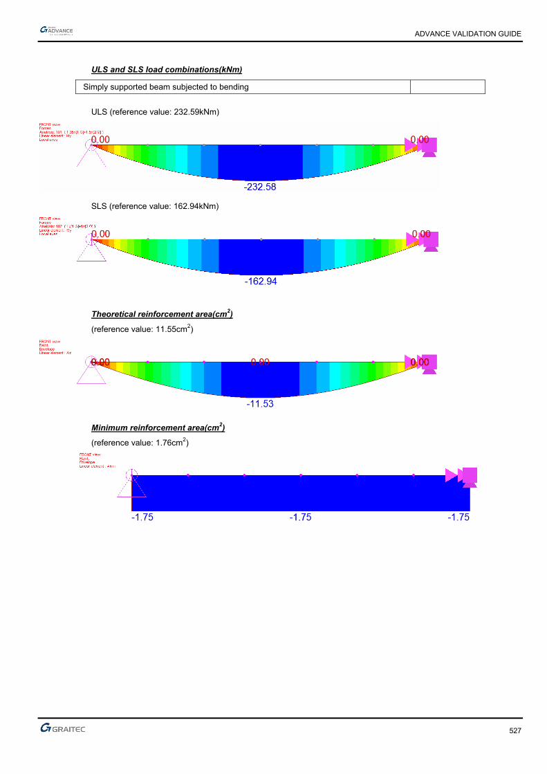
ADVANCE VALIDATION GUIDE
527
ULS and SLS load combinations(kNm)
Simply supported beam subjected to bending
ULS (reference value: 232.59kNm)
SLS (reference value: 162.94kNm)
Theoretical reinforcement area(cm2)
(reference value: 11.55cm2)
Minimum reinforcement area(cm2)
(reference value: 1.76cm2)
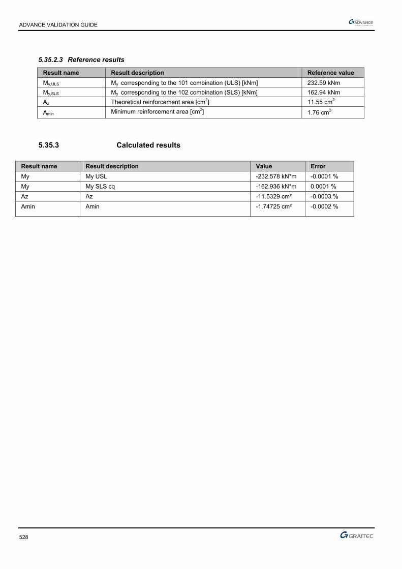
ADVANCE VALIDATION GUIDE
528
5.35.2.3 Reference results
Result name Result description Reference value
My,ULS My corresponding to the 101 combination (ULS) [kNm] 232.59 kNm
My,SLS My corresponding to the 102 combination (SLS) [kNm] 162.94 kNm
Az Theoretical reinforcement area [cm2] 11.55 cm2
Amin Minimum reinforcement area [cm2] 1.76 cm2
5.35.3 Calculated results
Result name Result description Value Error
My My USL -232.578 kN*m -0.0001 %
My My SLS cq -162.936 kN*m 0.0001 %
Az Az -11.5329 cm² -0.0003 %
Amin Amin -1.74725 cm² -0.0002 %

ADVANCE VALIDATION GUIDE
529
5.36 EC2 Test33: Verifying a square concrete column subjected to compression by nominal rigidity method- Bilinear stress-strain diagram (Class XC1)
Test ID: 5109
Test status: Passed
5.36.1 Description
Verifies a square concrete column subjected to compression by nominal rigidity method- Bilinear stress-strain diagram (Class XC1).
The column is made of concrete C30/37. The verification of the axial force, applied on top, at ultimate limit state is performed.
Nominal rigidity method.
The purpose of this test is to determine the second order effects by applying the method of nominal rigidity, and then calculate the frames by considering a section symmetrically reinforced.
The column is considered connected to the ground by a fixed connection (all the translations and rotations are blocked) and to the top part, the translations along X and Y axis are also blocked.
This test is based on the example from "Applications of Eurocode 2" (J. & JA Calgaro Cortade).
5.36.2 Background
Nominal rigidity method.
Verify the adequacy of a square cross section made from concrete C30/37.
The purpose of this test is to determine the second order effects by applying the method of nominal rigidity, and then calculate the frames by considering a section symmetrically reinforced.
5.36.2.1 Model description
■ Reference: Guide de validation Eurocode 2 EN 1992-1-1-2002;
■ Analysis type: static linear (plane problem);
■ Element type: linear.
The following load cases and load combination are used:
■ Loadings from the structure:
► 1260kN axial force
► The self-weight is neglected
■ Concrete cover 5cm
■ Concrete C30/37
■ Steel reinforcement S500B
■ Concrete age 28 days
■ Relative humidity 50%
■ Buckling length: L0=0.7*4.47=3.32mm
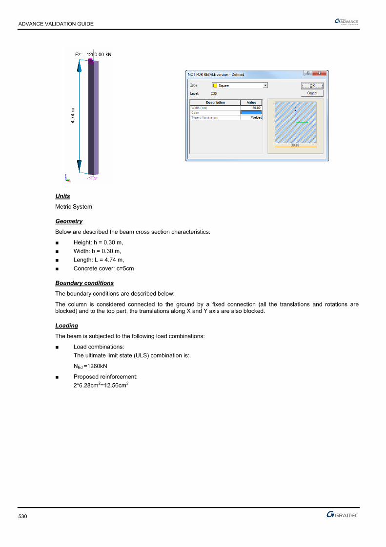
ADVANCE VALIDATION GUIDE
530
Units
Metric System
Geometry
Below are described the beam cross section characteristics:
■ Height: h = 0.30 m,
■ Width: b = 0.30 m,
■ Length: L = 4.74 m,
■ Concrete cover: c=5cm
Boundary conditions
The boundary conditions are described below:
The column is considered connected to the ground by a fixed connection (all the translations and rotations are blocked) and to the top part, the translations along X and Y axis are also blocked.
Loading
The beam is subjected to the following load combinations:
■ Load combinations:
The ultimate limit state (ULS) combination is:
NEd =1260kN
■ Proposed reinforcement:
2*6.28cm2=12.56cm2
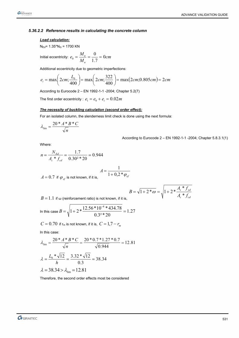
ADVANCE VALIDATION GUIDE
531
5.36.2.2 Reference results in calculating the concrete column
Load calculation:
NEd= 1.35*NG = 1700 KN
Initial eccentricity: cmM
Me
u
u 07.1
00
Additional eccentricity due to geometric imperfections:
cmcmcmcmL
cmei 2805.0;2max400
322;2max
400;2max 0
According to Eurocode 2 – EN 1992-1-1 -2004; Chapter 5.2(7)
The first order eccentricity : meee i 02.001
The necessity of buckling calculation (second order effect):
For an isolated column, the slenderness limit check is done using the next formula:
n
CBA ***20lim
According to Eurocode 2 – EN 1992-1-1 -2004; Chapter 5.8.3.1(1)
Where:
944.020*²30.0
7.1
*
cdc
Ed
fA
Nn
7.0A if ef is not known, if it is, ef
A*2,01
1
1.1B if ω (reinforcement ratio) is not known, if it is, cdc
yds
fA
fAB
*
**21*21
In this case 27.120*²3.0
78.434*10*56.12*21
4
B
70.0C if rm is not known, if it is, mrC 7,1
In this case:
81.12944.0
7.0*27.1*7.0*20***20lim
n
CBA
34.383.0
12*32.312*0 h
L
81.1234.38 lim
Therefore, the second order effects most be considered
ADVANCE VALIDATION GUIDE
532
Effective creep coefficient calculation:
The creep coefficient is calculated using the next formula:
Ed
EQPef M
Mt ., 0
According to Eurocode 2 – EN 1992-1-1 -2004; Chapter 5.8.4(2)
Where:
0,t creep coefficient
EQPM serviceability firs order moment under quasi-permanent load combination
EdM ULS first order moment (including the geometric imperfections)
The ratio of the moment is in this case:
74.07.1
26.1
*
*
1
1
0
0 ed
eqp
ed
eqp
Ed
Eqp
N
N
eN
eN
M
M
),( 0tis the final value of the creep:
)(*)(*),( 00 tft cmRH
With:
t0 is the concrete age
2130
***1.0100
11
h
RH
RH
121 if MPafcm 35
if not
7.0
1
35
cmf
and
2.0
2
35
cmf
RH relative humidity: RH=50%
h0= mean radius of the element in mm
mmu
Ach 150
300300*2
300*300*2*20
u=column section perimeter
MPaMPafcm 3538944.0
38
357.0
1
and
984.038
352.0
2

ADVANCE VALIDATION GUIDE
533
86.1984.0*944.0*150*1.0
100
501
1***1.0100
11
32130
h
RH
RH
48.2488.0*73.2*86.1)(*)(*),( 00 tft cmRH
835.174.0*48.2*),(0
00
Ed
Eqpef M
Mt
835.2835.111 ef
Calculation of nominal rigidity:
The nominal rigidity of a post or frame member, it is estimated from the following formula:
sssccdc IEKIEKEI ****
According to Eurocode 2 – EN 1992-1-1 -2004; Chapter 5.8.7.2 (1)
ec
kkK
1
* 21
835.21 ef
22.120
30
201 ckfk
170
*2
nk
944.020*²3.0
7.1
*
cdc
Ed
fA
Nn
34.38
20.0213.0170
34.38*944.0
170
*22 k
nk
086.0835.2
20.022.1
121
ec
kkK
CE
cmcd
EE
MPaf
E ckcm 32837
10
825*22
10
8*22
3.03.0
MPaE
ECE
cmcd 27364
2.1
32837
433
000675.012
3.0*3.0
12
*m
hbIc
Ks=1

ADVANCE VALIDATION GUIDE
534
Es = 200 Gpa
45242
10*256.12
05.025.0*
2
10*56.12*2
2
'*
2*2 m
ddAI theos
²1.410*256.1*200000*1000675.0*27364*086.0 5 MNmEI
MNL
EIN
fB 67.3
²32.3
10.4*²
²
*²
234.18
²²
0
c
MNm
N
NMM
Ed
BEdEd 070.0
17.1
67.3234.1
1*034.01
1*0
The calculation made with flexural:
MNNEd 7.1and
MNmMEd 070.0,
Therefore, a 2*6.64cm2 reinforcement area is obtained.
The calculated reinforcement is very close to the initial assumption (2*6.28cm2)
It is not necessary to continue the calculations; it retains a section of 2*6.64cm2
It sets up 4HA20 (2*6.28=12.57cm2)
Finite elements modeling
■ Linear element: S beam,
■ 7 nodes,
■ 1 linear element.

ADVANCE VALIDATION GUIDE
535
Theoretical reinforcement area(cm2)
(reference value: 6.54cm2)
Theoretical value (cm2)
(reference value: 13.08 cm2)
5.36.2.3 Reference results
Result name Result description Reference value
Az Reinforcement area [cm2] 6.54 cm2
5.36.3 Calculated results
Result name Result description Value Error
Az Az -6.53808 cm² 0.0001 %

ADVANCE VALIDATION GUIDE
536
5.37 EC2 Test34: Verifying a rectangular concrete column subjected to compression on the top – Method based on nominal stiffness - Bilinear stress-strain diagram (Class XC1)
Test ID: 5114
Test status: Passed
5.37.1 Description
Verifies the adequacy of a rectangular cross section column made of concrete C30/37. The verification of the axial stresses applied on top, at ultimate limit state is performed.
Method based on nominal stiffness - The purpose of this test is to determine the second order effects by applying the method of nominal stiffness, and then calculate the frames by considering a section symmetrically reinforced.
The column is considered connected to the ground by a fixed connection and free at the top part.
5.37.2 Background
Method based on nominal stiffness
Verifies the adequacy of a rectangular cross section made of concrete C30/37.
The purpose of this test is to determine the second order effects by applying the method of nominal stiffness, and then calculate the frames by considering a section symmetrically reinforced.
5.37.2.1 Model description
■ Reference: Guide de validation Eurocode 2 EN 1992-1-1-2002;
■ Analysis type: static linear (plane problem);
■ Element type: linear.
The following load cases and load combination are used:
■ Loadings from the structure:
► 300kN axial force
► The self-weight is neglected
■ Exploitation loadings:
► 500kN axial force
■ 3,02
■ The ultimate limit state (ULS) combination is: Cmax = 1.35 x G + 1.5 x Q
■ Characteristic combination of actions: CCQ = 1.0 x G + 1.0 x Q
■ Concrete cover 5cm
■ Transversal reinforcement spacing a=30cm
■ Concrete C30/37
■ Steel reinforcement S500B
■ The column is considered isolated and braced

ADVANCE VALIDATION GUIDE
537
Units
Metric System
Geometry
Below are described the beam cross section characteristics:
■ Height: h = 0.40 m,
■ Width: b = 0.60 m,
■ Length: L = 4.00 m,
■ Concrete cover: c = 5 cm along the long section edge and 3cm along the short section edge
Boundary conditions
The boundary conditions are described below:
The column is considered connected to the ground by a fixed connection and free to the top part.
Loading
The beam is subjected to the following load combinations:
■ Load combinations:
The ultimate limit state (ULS) combination is:
NEd =1.35*0.30+1.5*0.50=1.155MN
NQP=1.35*0.30+0.30*0.50=0.450MN
■
ADVANCE VALIDATION GUIDE
538
5.37.2.2 Reference results in calculating the concrete column
Geometric characteristics of the column:
The column has a fixed connection on the bottom end and is free on the top end, therefore, the buckling length is considered to be:
mll 84*2*20
According to Eurocode 2 – EN 1992-1-1 -2004; Chapter 5.8.3.2(1); Figure 5.7 b)
Calculating the slenderness of the column:
28.6940.0
8*32*32 0 a
l
Effective creep coefficient calculation:
The creep coefficient is calculated using the next formula:
Ed
EQPef M
Mt ., 0
According to Eurocode 2 – EN 1992-1-1 -2004; Chapter 5.8.4(2)
Where:
0,t creep coefficient
EQPM serviceability first order moment under quasi-permanent load combination
EdM ULS first order moment (including the geometric imperfections)
The ratio between moments becomes:
39.0155.1
450.0
*
*
1
1
0
0 ed
eqp
ed
eqp
Ed
Eqp
N
N
eN
eN
M
M
The creep coefficient 0,t is defined as:
)(*)(*),( 00 tft cmRH
MPaf
fcm
cm 73.2830
8.168.16)(
488.0281.0
1
1.0
1)(
20.020.00
0
t
t (for t0= 28 days concrete age).
213
0
***1.0100
11
h
RH
RH
RH = relative humidity; RH=50%
Where 121 if MPafcm 35 if not
7.0
1
35
cmf and
2.0
2
35
cmf
ADVANCE VALIDATION GUIDE
539
mmu
Ach 240
600400*2
600*400*2*20
MPaMPafcm 3538 ,
Therefore:
944.038
35357.07.0
1
cmf and 984.0
38
35352.02.0
2
cmf
73.1984.0*944.0*240*1.0
100
501
1***1.0100
11
3213
0
h
RH
RH
30.2488.0*73.2*73.1)(*)(*),( 00 tft cmRH
The effective creep coefficient calculation:
90.039.0*30.2*, 0 Ed
EQPef M
Mt
According to Eurocode 2 – EN 1992-1-1 -2004; Chapter 5.8.4(2)
The necessity of buckling calculation (second order effect):
For an isolated column, the slenderness limit check is done using the next formula:
n
CBA ***20lim
According to Eurocode 2 – EN 1992-1-1 -2004; Chapter 5.8.3.1(1)
Where:
241.020*60.0*40.0
155.1
*
cdc
Ed
fA
Nn
85.090.0*2.01
1
*2,01
1
ef
A
1.1*21 B because the reinforcement ratio in not yet known
70.07,1 mrC because the ratio of the first order moment is not known
66.26112.0
7.0*1.1*85.0*20lim
66.2628.69 lim
Therefore, the second order effects must be considered.

ADVANCE VALIDATION GUIDE
540
5.37.2.3 The eccentricity calculation and the corrected loads on ULS:
Initial eccentricity:
No initial eccentricity because the post is subjected only in simple compression.
Additional eccentricity:
ml
ei 02.0400
8
4000
First order eccentricity- stresses correction:
mmmm
mmmmmm
hmm
e 203.13
20max
30
40020
max30
20max0
According to Eurocode 2 – EN 1992-1-1 -2004; Chapter 6.1.(4)
The corrected solicitations which are taken into account when calculating the column under combined bending effort and compression are:
NEd= 1.155MN
MEd= 1.155*0.02=0.0231MNm
Reinforcement calculation in the first order situation:
When using the nominal stiffness method, a starting section frame is needed. For this it will be used a concrete section considering only the first order effects.
Advance Design iterates as many time as necessary.
The needed frames will be determined assuming a compound bending with compressive stress. All the results above were obtained in the center of gravity for the concrete section alone. The stresses must be reduced in the centroid of the tensioned steel.
First order moment in the centroid of the tensioned reinforcement is:
MNmh
dNMM Gua 196.02
40.035.0*155.10231.0)
2(*0
Verification if the section is partially compressed:
496,0)35,0
40,0*4,01(*
35,0
40,0*8,0)*4,01(**8,0
d
h
d
hBC
133.020*²35.0*60.0
196.0
*²*
cdw
uacu fdb
M
BCcu 496.0133.0 therefore the section is partially compressed.
ADVANCE VALIDATION GUIDE
541
Calculations of steel reinforcement in pure bending:
133.0cu
179,0)133,0*21(1*25,1 u
mdz uc 325,0)179,0*4,01(*35,0)*4,01(*
²87.1378,434*325,0
196,0
*cm
fz
MA
ydc
ua
Calculations of steel reinforcement in combined bending:
For the combined bending:
24 69.1278.434
155.110*87.13' cm
fN
AAyd
The minimum reinforcement percentage:
2min, 80.4*002.0²66.2
78.434
155.1*10.0*10,0cmAcm
f
NA c
yd
Eds
The reinforcement will be 4HA12 + 2HA10 representing 6.09cm2.
The second order effects calculation:
The second order effect will be determined by applying the method of nominal stiffness:
Calculation of nominal stiffness:
It is estimated nominal stiffness of a post or frame member from the following formula:
sssccdc IEKIEKEI ****
With:
2.1cm
cd
EE
MPaMPaff ckcm 388
MPaf
E cmcm 32837
10
38*22000
10*22000
3.03.0
MPaE
E cmcd 27364
2.1
32837
2.1
410.2,312
40.0*60.0
12
* 333
mhb
Ic
(concrete only inertia)
MPaEs 200000
sI : Inertia of the steel rebars
00254.040.0*60.0
10.09,6 4
c
s
A
A

ADVANCE VALIDATION GUIDE
542
01.0002.0 c
s
A
A
Mpaf
k ck 22.120
30
201
241.020*60.0*40.0
155.1
.
cdc
Ed
fA
Nn
20.0098.0170
28.69*241.0
170*2
nk
410.37,105.02
40.0*
2
10.09,6*2
2*
2*2 5
242
mchA
I ss
1sK and 063.090.01
098.0*22.1
1
* 21
ef
c
kkK
Therefore:
²2566.810*37,1*200000*110*2,3*27364*063.0 53 MNmEI
Stresses correction:
The total moment, including second order effects, is defined as a value plus the time of the first order:
11*0
Ed
BEdEd
N
NMM
MNmM Ed 0231.00 (moment of first order (ULS) taking into account geometric imperfections)
(normal force acting at ULS).
0
²
c
and 80 c the moment is constant (no horizontal force at the top of post).
234.18
²
MNl
EINB 27327.1
²8
2566.8*²*² 2
0
The second order efforts are:
MNNEd 155.12
mMNMEd .3015.02
The reinforcement calculations considering the second order effect:
The reinforcement calculations for the combined flexural, under the second order effect, are done using the Graitec EC2 tools. The obtained section is null, therefore the minimum reinforcement area defined above is sufficient for the defined efforts.
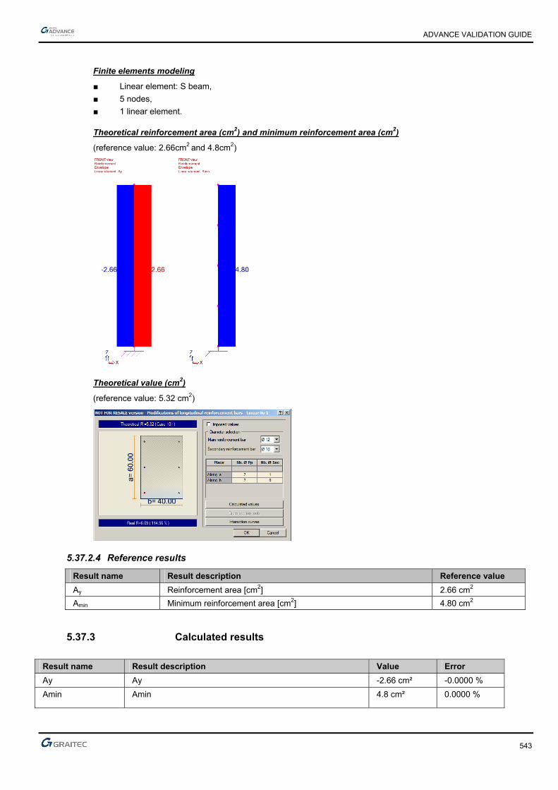
ADVANCE VALIDATION GUIDE
543
Finite elements modeling
■ Linear element: S beam,
■ 5 nodes,
■ 1 linear element.
Theoretical reinforcement area (cm2) and minimum reinforcement area (cm2)
(reference value: 2.66cm2 and 4.8cm2)
Theoretical value (cm2)
(reference value: 5.32 cm2)
5.37.2.4 Reference results
Result name Result description Reference value
Ay Reinforcement area [cm2] 2.66 cm2
Amin Minimum reinforcement area [cm2] 4.80 cm2
5.37.3 Calculated results
Result name Result description Value Error
Ay Ay -2.66 cm² -0.0000 %
Amin Amin 4.8 cm² 0.0000 %

ADVANCE VALIDATION GUIDE
544
5.38 EC2 Test32: Verifying a square concrete column subjected to compression and rotation moment to the top – Method based on nominal curvature- Bilinear stress-strain diagram (Class XC1)
Test ID: 5102
Test status: Passed
5.38.1 Description
Verifies a square concrete column subjected to compression and rotation moment to the top – Method based on nominal curvature- Bilinear stress-strain diagram (Class XC1).
The column made of concrete C25/30. The verification of the axial stresses and rotation moment, applied on top, at ultimate limit state is performed.
The purpose of this test is to determine the second order effects by applying the method of nominal curvature, and then calculate the frames by considering a section symmetrically reinforced.
5.38.2 Background
Method based on nominal curvature
Verifies the adequacy of a square cross section made from concrete C25/30.
5.38.2.1 Model description
■ Reference: Guide de validation Eurocode 2 EN 1992-1-1-2002;
■ Analysis type: static linear (plane problem);
■ Element type: linear.
The following load cases and load combination are used:
■ Loadings from the structure:
► 15t axial force
► 1.5tm rotation moment applied to the column top
► The self-weight is neglected
■ Exploitation loadings:
► 6.5t axial force
► 0.7tm rotation moment applied to the column top
► 3,02
► The ultimate limit state (ULS) combination is: Cmax = 1.35 x G + 1.5 x Q
► Characteristic combination of actions: CCQ = 1.0 x G + 1.0 x Q
► Concrete cover 5cm
► Transversal reinforcement spacing a=30cm
► Concrete C25/30
► Steel reinforcement S500B
► The column is considered isolated and braced
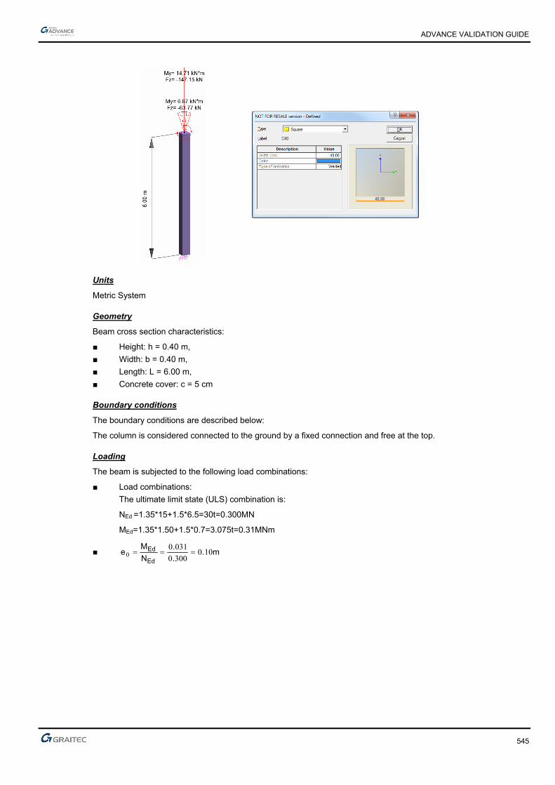
ADVANCE VALIDATION GUIDE
545
Units
Metric System
Geometry
Beam cross section characteristics:
■ Height: h = 0.40 m,
■ Width: b = 0.40 m,
■ Length: L = 6.00 m,
■ Concrete cover: c = 5 cm
Boundary conditions
The boundary conditions are described below:
The column is considered connected to the ground by a fixed connection and free at the top.
Loading
The beam is subjected to the following load combinations:
■ Load combinations:
The ultimate limit state (ULS) combination is:
NEd =1.35*15+1.5*6.5=30t=0.300MN
MEd=1.35*1.50+1.5*0.7=3.075t=0.31MNm
■ m..
.
N
Me
Ed
Ed 1003000
03100

ADVANCE VALIDATION GUIDE
546
5.38.2.2 Reference results in calculating the concrete column
Geometric characteristics of the column:
The column has a fixed connection on the bottom end and is free on the top end, therefore, the buckling length is considered to be:
mll 12*20
According to Eurocode 2 – EN 1992-1-1 -2004; Chapter 5.8.3.2(1); Figure 5.7 b)
Calculating the slenderness of the column:
10440.0
12*32*32 0 a
l
Effective creep coefficient calculation:
The creep coefficient is calculated using the next formula:
Ed
EQPef M
Mt ., 0
According to Eurocode 2 – EN 1992-1-1 -2004; Chapter 5.8.4(2)
Where:
0,t creep coefficient
EQPM serviceability firs order moment under quasi-permanent load combination
EdM ULS first order moment (including the geometric imperfections)
First order eccentricity evaluation:
ieee 01
mei 03.0
The first order moment provided by the quasi-permanent loads:
meN
Meee i
Eqp
Eqpi 13.030.0
65.0*30.015
70.0*30.050.1
0
001
tNEqp 95.1670.0*30.050.11
MNmtmeNM EqpEqp 022.020.213.0*95.16* 111
The first order ULS moment is defined latter in this example:
The creep coefficient 0,t is defined as follows:
)(*)(*),( 00 tft cmRH
92.2825
8.168.16)(
cm
cmf
f
488.0281.0
1
1.0
1)(
20.020.00
0
t
t (for t0= 28 days concrete age).
ADVANCE VALIDATION GUIDE
547
30*1.0
1001
1h
RH
RH
85.1200*1.0
100
501
1200400400*2
400*400*2*230
RHmm
u
Ach
64.2488.0*92.2*85.1)(*)(*),( 00 tft cmRH
The effective creep coefficient calculation:
49.1039.0
022.0*64.2*, 0
Ed
EQPef M
Mt
According to Eurocode 2 – EN 1992-1-1 -2004; Chapter 5.8.4(2)
The necessity of buckling calculation (second order effect):
For an isolated column, the slenderness limit verification is done using the next formula:
n
CBA ***20lim
According to Eurocode 2 – EN 1992-1-1 -2004; Chapter 5.8.3.1(1)
Where:
112.067.16*²40.0
300.0
*
cdc
Ed
fA
Nn
77.049.1*2.01
1
*2,01
1
ef
A
1.1*21 B because the reinforcement ratio in not yet known
70.07,1 mrC because the ratio of the first order moment is unknown
43.35112.0
7.0*1.1*77.0*20lim
43.35104 lim
Therefore, the second order effects most be considered.
The second order effects; The buckling calculation:
The stresses for the ULS load combination are:
NEd= 1.35*15 + 1.50*6.50= 30 t = 0,300MN
MEd= 1.35*1.50 + 1.50*0.7= 3.075 t = 0,031MNm
Therefore, it must be determined:
■ The eccentricity of the first order ULS moment, due to the stresses applied
■ The additional eccentricity considered for the geometrical imperfections

ADVANCE VALIDATION GUIDE
548
Initial eccentricity:
mN
Me
Ed
Ed 10.0300.0
031.00
Additional eccentricity:
ml
ei 03.0400
12
4000
The first order eccentricity: stresses correction:
The forces correction, used for the combined flexural calculations:
MNNEd 300.0
meee i 13.001
MNmNeM EdEd 039.0300.0*)03.010.0(*1
0*eNM Ed
mmmm
mmmmmm
hmm
e 203.13
20max
30
40020
max30
20max0
According to Eurocode 2 – EN 1992-1-1 -2004; Chapter 6.1.(4)
Reinforcement calculation in the first order situation:
To play the nominal rigidity method a starting section frame is needed. For this it will be used a concrete section considering only the first order effects.
Advance Design iterates as many time as necessary.
The needed frames will be determined assuming a compound bending with compressive stress. All the results above were obtained in the center of gravity for the concrete section alone. The stresses must be reduced in the centroid of the tensioned steel.
MNmh
dNMM Gua 084.02
40.035.0*300.0039.0)
2(*0
Verification if the section is partially compressed:
496,0)35,0
40,0*4,01(*
35,0
40,0*8,0)*4,01(**8,0
d
h
d
hBC
103.067.16*²35.0*40.0
084.0
*²*
cdw
uacu fdb
M
BCcu 496.0103.0 therefore the section is partially compressed.
ADVANCE VALIDATION GUIDE
549
Calculations of steel reinforcement in pure bending:
Calculations of steel reinforcement in combined bending:
For the combined bending:
24 06.178.434
300.010*84.5' cm
fN
AAyd
The minimum reinforcement percentage:
2min, 02.3*002.0²69.0
78.434
300.0*10.0*10,0cmAcm
f
NA c
yd
Eds
The reinforcement will be 4HA10 representing a 3.14cm2 section
The second order effects calculation:
The second order effect will be determined by applying the method of nominal curvature:
Calculation of nominal curvature:
Considering a symmetrical reinforcement 4HA10 (3.14cm ²), the curvature can be determined by the following formula:
0
1**
1
rKK
r r
According to Eurocode 2 – EN 1992-1-1 -2004; Chapter 5.8.8.3 (1)
With:
1
0
0138.035.0*45.0
200000
78.434
*45,0*45,0
1 md
E
f
drs
yd
yd
rK : is a correction factor depending on axial load,=> 1
balu
ur nn
nnK
112.067.16*²40.0
300.0
*
cdc
Ed
fA
Nn
0512.067.16*²40.0
78.434*10.14,3
*
* 4
cdc
yds
fA
fA
0512.10512.011 un
4,0baln
ADVANCE VALIDATION GUIDE
550
1144.140.00512.1
112.00512.1
rr KK
K : is a factor for taking account of creep=> 1*1 efK
218.0150
104
200
2535.0
15020035,0
ckf
11675.049.1*218.01*1 KK ef
Therefore the curvature becomes:
1
0
0138.01
**1 m
rKK
r r
Calculation moment:
20 MMM EdEd
Where:
EdM 0 : first order moment including the geometrical imperfections.
2M : second order moment
The second order moment must be calculated from the curvature:
22 *eNM Ed
mc
l
re 199.0
10
²12*0138.0*
1 20
2
MNmeNM Ed 0597.0199.0*300.0* 22
MNmMMM EdEd 099.00597.0039.020
The frame must be sized corresponding the demands of the second order effects:
MNNEd 300.0
MNmMEd 099.0
Reinforcement calculation corresponding to the second order:
The input parameters in the diagram are:
093.067.16*²40.0*40.0
099.0
** 2
cd
Ed
fhb
M
112.067.16*40.0*40.0
300.0
**
cd
Ed
fhb
Nv

ADVANCE VALIDATION GUIDE
551
150ω . ; => ²cm..
.*².*.
f
f*h*b*A
yd
cds 209
78434
6716400150ω; which means 4.60cm2 per side.
Buckling checking
The verification will be made considering the reinforcement found previously (9.20cm2)
The curvature evaluation:
The frames have an influence on the rK parameter only:
1
0
0138.01 mr
1
balu
ur nn
nnK
112.0n
15.067.16*²40.0
78.434*10*20,9
*
* 4
cdc
yds
fA
fA
15.115.011 un
4,0baln
11384.140.015.1
112.015.1
rr KK
1K : coefficient that takes account of the creep => 1*1 efK
The curvature becomes:
1
0
0138.01
**1 m
rKK
r r
It was obtained the same curvature and therefore the same second order moment, which validates the section reinforcement found.
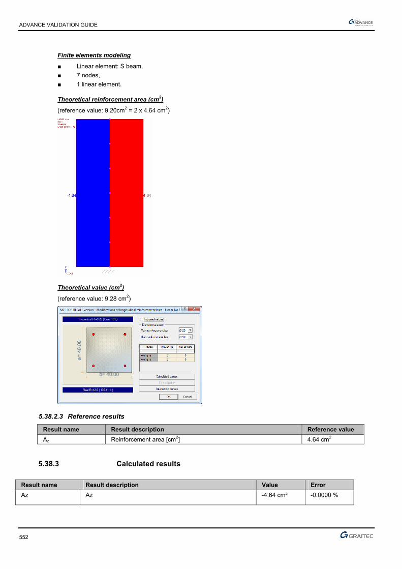
ADVANCE VALIDATION GUIDE
552
Finite elements modeling
■ Linear element: S beam,
■ 7 nodes,
■ 1 linear element.
Theoretical reinforcement area (cm2)
(reference value: 9.20cm2 = 2 x 4.64 cm2)
Theoretical value (cm2)
(reference value: 9.28 cm2)
5.38.2.3 Reference results
Result name Result description Reference value
Az Reinforcement area [cm2] 4.64 cm2
5.38.3 Calculated results
Result name Result description Value Error
Az Az -4.64 cm² -0.0000 %

ADVANCE VALIDATION GUIDE
553
5.39 EC2 Test 24: Verifying the shear resistance for a rectangular concrete beam with vertical transversal reinforcement - Bilinear stress-strain diagram (Class XC1)
Test ID: 5058
Test status: Passed
5.39.1 Description
Verifies a rectangular cross section beam made from concrete C20/25 to resist simple bending. For this test, the shear force diagram will be generated. The design value of the maximum shear force which can be sustained by the member, limited by crushing of the compression struts (VRd,max) will be determined, along with the cross-sectional area of the shear reinforcement (Asw) calculation.
5.39.2 Background
Verifies a rectangular cross section beam made from concrete C20/25 to resist simple bending. For this test, the shear force diagram will be generated. The design value of the maximum shear force which can be sustained by the member, limited by crushing of the compression struts (VRd,max) will be determined, along with the cross-sectional area of the shear reinforcement (Asw) calculation.
5.39.2.1 Model description
■ Reference: Guide de validation Eurocode 2 EN 1992-1-1-2002;
■ Concrete C20/25
■ Reinforcement steel: S500B
■ Analysis type: static linear (plane problem);
■ Element type: linear.
The following load cases and load combination are used:
■ Loadings from the structure:
The dead load will be represented by a punctual load of 105kN
■ Exploitation loadings:
The live load will be considered from one point load of 95kN
■ Structural class: S1
■ Reinforcement steel ductility: Class B
■ The reinforcement will be displayed like in the picture below:
The objective is to verify:
■ The shear stresses results
■ The cross-sectional area of the shear reinforcement, Asw

ADVANCE VALIDATION GUIDE
554
Units
Metric System
Geometry
Beam cross section characteristics:
■ Height: h = 0.50 m,
■ Width: b = 0.20 m,
■ Length: L = 3.00 m,
■ Concrete cover: c=3.5cm
■ Effective height: d=h-(0.06*h+ebz)=0.435m; d’=ehz=0.035m
■ Stirrup slope: = 90°
■ Strut slope: θ=30˚
Boundary conditions
The boundary conditions are described below:
■ Outer:
► Support at start point (x = 0) restrained in translation along X, Y and Z,
► Support at end point (x = 5.30) restrained in translation along Y, Z and rotation along X
■ Inner: None.
Loading:
For a beam subjected to a point load, Pu, the shear stresses are defined by the formula below:
l
aPV uEd 1
According to EC2 the Pu point load is defined by the next formula:
Pu = 1,35*Pg + 1,50*Pq=1.35*105kN=1.50*95kN=284.25kN
In this case, (a = 1 m; l = 3 m):
KNVEd 5,1893
11*25,284
Note: In Advance Design, the shear reduction is not taken into account. These are the values corresponding to an unreduced shear that will be used for further calculations.
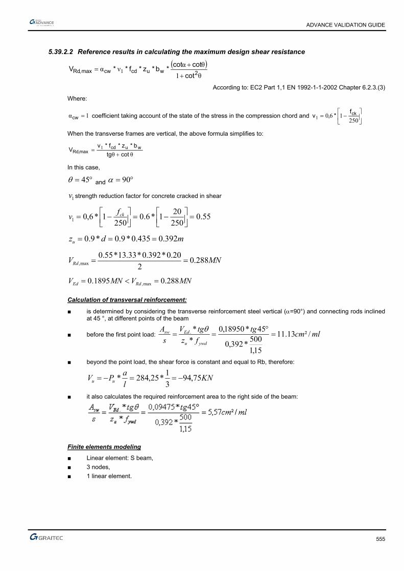
ADVANCE VALIDATION GUIDE
555
5.39.2.2 Reference results in calculating the maximum design shear resistance
θ1
θανα 1 2wucdcwmax,Rd
cot
cotcot*b*z*f**V
According to: EC2 Part 1,1 EN 1992-1-1-2002 Chapter 6.2.3.(3)
Where:
1α cw coefficient taking account of the state of the stress in the compression chord and
2501601
ckf*,v
When the transverse frames are vertical, the above formula simplifies to:
θθ1
cottg
b*z*f*vV wucd
max,Rd
In this case,
45 and 90
1v strength reduction factor for concrete cracked in shear
55.0250
201*6.0
2501*6,01
ckfv
mdzu 392.0435.0*9.0*9.0
MNVRd 288.02
20.0*392.0*33.13*55.0max,
MNVMNV RdEd 288.01895.0 max,
Calculation of transversal reinforcement:
■ is determined by considering the transverse reinforcement steel vertical (=90°) and connecting rods inclined at 45 °, at different points of the beam
■ before the first point load: mlcmtg
fz
tgV
s
A
ywdu
Edsw /²13.11
15,1
500*392,0
45*18950,0
*
*.
■ beyond the point load, the shear force is constant and equal to Rb, therefore:
KNl
aPV uu 75,94
3
1*25,284*
■ it also calculates the required reinforcement area to the right side of the beam:
Finite elements modeling
■ Linear element: S beam,
■ 3 nodes,
■ 1 linear element.

ADVANCE VALIDATION GUIDE
556
Advance Design gives the following results for Atz (cm2/ml)
5.39.2.3 Reference results
Result name Result description Reference value
Fz,1 Fz corresponding to the 101 combination (ULS) x=1m [kNm] 189.5 kN
Fz,2 Fz corresponding to the 101 combination (ULS) x=1.01m [kNm] 94.75 kN
At,z,1 Theoretical reinforcement area x=1m [cm2/ml] 11.13 cm2/ml
At,z,2 Theoretical reinforcement area x=1.01m [cm2/ml] 5.57 cm2/ml
5.39.3 Calculated results
Result name Result description Value Error
Fz Fz,1 -189.5 kN -0.0000 %
Fz Fz,2 94.75 kN 0.0000 %
Atz Atz,1 11.1328 cm² 0.0002 %
Atz Atz,2 5.56641 cm² 0.0000 %
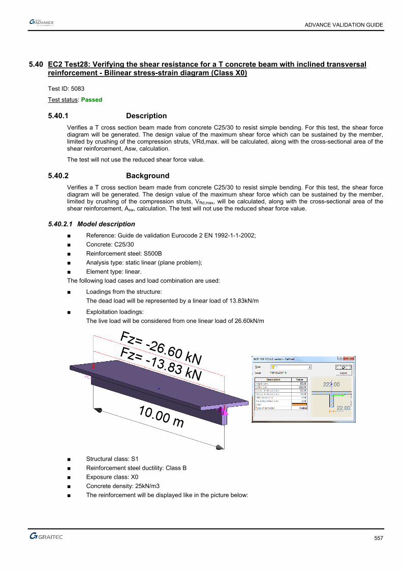
ADVANCE VALIDATION GUIDE
557
5.40 EC2 Test28: Verifying the shear resistance for a T concrete beam with inclined transversal reinforcement - Bilinear stress-strain diagram (Class X0)
Test ID: 5083
Test status: Passed
5.40.1 Description
Verifies a T cross section beam made from concrete C25/30 to resist simple bending. For this test, the shear force diagram will be generated. The design value of the maximum shear force which can be sustained by the member, limited by crushing of the compression struts, VRd,max. will be calculated, along with the cross-sectional area of the shear reinforcement, Asw, calculation.
The test will not use the reduced shear force value.
5.40.2 Background
Verifies a T cross section beam made from concrete C25/30 to resist simple bending. For this test, the shear force diagram will be generated. The design value of the maximum shear force which can be sustained by the member, limited by crushing of the compression struts, VRd,max, will be calculated, along with the cross-sectional area of the shear reinforcement, Asw, calculation. The test will not use the reduced shear force value.
5.40.2.1 Model description
■ Reference: Guide de validation Eurocode 2 EN 1992-1-1-2002;
■ Concrete: C25/30
■ Reinforcement steel: S500B
■ Analysis type: static linear (plane problem);
■ Element type: linear.
The following load cases and load combination are used:
■ Loadings from the structure:
The dead load will be represented by a linear load of 13.83kN/m
■ Exploitation loadings:
The live load will be considered from one linear load of 26.60kN/m
■ Structural class: S1
■ Reinforcement steel ductility: Class B
■ Exposure class: X0
■ Concrete density: 25kN/m3
■ The reinforcement will be displayed like in the picture below:

ADVANCE VALIDATION GUIDE
558
The objective is to:
■ Verify the shear stresses results
■ Verify the transverse reinforcement
■ Verify the transverse reinforcement distribution by the Caqout method
■ Identify the steel sewing
Units
Metric System
Geometry
Below are described the beam cross section characteristics:
■ Length: L = 10.00 m,
■ Concrete cover: c=3.5cm
■ Effective height: d=h-(0.06*h+ebz)=0.764m; d’=ehz=0.035m
■ Stirrup slope: = 90°
■ Strut slope: θ=30˚
Boundary conditions
The boundary conditions are described below:
■ Outer:
► Support at start point (x=0) restrained in translation along X, Y and Z,
► Support at end point (x = 10.00) restrained in translation along Y, Z and rotation along X
■ Inner: None.

ADVANCE VALIDATION GUIDE
559
Loading:
For a beam under a uniformly distributed load Pu, the shear force is defined by the following equation:
2
**)(
lPxPxV u
u
For the beam end, (x=0) the shear force will be:
kNlP
V uEd 9,292
2
10*57,58
2
*
In the following calculations, the negative sign of the shear will be neglected, as this has no effect in the calculations.
Note: In Advance Design, the shear reduction is not taken into account. These are the values corresponding to an unreduced shear that will be used for further calculations.
5.40.2.2 Reference results in calculating the maximum design shear resistance
cot
***1max,
tg
bzfvV wucdRd
According to: EC2 Part 1,1 EN 1992-1-1-2002 Chapter 6.2.3.(3)
In this case:
30 and 90
1v strength reduction factor for concrete cracked in shear
54.0250
251*6.0
2501*6,01
ckfv
mdzu 688.0764.0*9.0*9.0
MNtg
VRd 590.030cot30
22.0*688.0*67.16*54.0max,
MNVMNV RdEd 590.0293.0 max,
Calculation of transverse reinforcement:
The transverse reinforcement is calculated using the following formula:
mlcmtg
fz
tgV
s
A
ywdu
Edsw /²66.5
15,1
500*688.0
30*293.0
*
*.

ADVANCE VALIDATION GUIDE
560
Finite elements modeling
■ Linear element: S beam,
■ 11 nodes,
■ 1 linear element.
Advance Design gives the following results for Atz (cm2/ml)
5.40.2.3 Reference results
Result name Result description Reference value
Fz Fz corresponding to the 101 combination (ULS) [kNm] 292.9 kN
At,z Theoretical reinforcement area [cm2/ml] 5.66 cm2/ml
5.40.3 Calculated results
Result name Result description Value Error
Fz Fz -292.852 kN -0.0002 %
Atz Atz 5.65562 cm² 0.0000 %
ADVANCE VALIDATION GUIDE
561
5.41 EC2 Test31: Verifying a square concrete column subjected to compression and rotation moment to the top - Bilinear stress-strain diagram (Class XC1)
Test ID: 5101
Test status: Passed
5.41.1 Description
Nominal rigidity method.
Verifies the adequacy of a rectangular cross section column made from concrete C25/30.
The purpose of this test is to determine the second order effects by applying the method of nominal rigidity, and then calculate the frames by considering a section symmetrically reinforced. Verifies the column to resist simple bending. The verification of the axial stresses and rotation moment, applied on top, at ultimate limit state is performed.
The column is considered connected to the ground by a fixed connection and free to the top part.
5.41.2 Background
Nominal rigidity method.
Verifies the adequacy of a rectangular cross section made from concrete C25/30.
The purpose of this test is to determine the second order effects by applying the method of nominal rigidity, and then calculate the frames by considering a section symmetrically reinforced.
5.41.2.1 Model description
■ Reference: Guide de validation Eurocode 2 EN 1992-1-1-2002;
■ Analysis type: static linear (plane problem);
■ Element type: linear.
The following load cases and load combination are used:
■ Loadings from the structure:
► 15t axial force
► 1.5tm rotation moment applied to the column top
► The self-weight is neglected
■ Exploitation loadings:
► 6.5t axial force
► 0.7tm rotation moment applied to the column top
■ 3,02
■ The ultimate limit state (ULS) combination is: Cmax = 1.35 x G + 1.5 x Q
■ Characteristic combination of actions: CCQ = 1.0 x G + 1.0 x Q
■ Concrete cover 5cm
■ Transversal reinforcement spacing a=30cm
■ Concrete C25/30
■ Steel reinforcement S500B
■ The column is considered isolated and braced

ADVANCE VALIDATION GUIDE
562
Units
Metric System
Geometry
Below are described the beam cross section characteristics:
■ Height: h = 0.40 m,
■ Width: b = 0.40 m,
■ Length: L = 6.00 m,
■ Concrete cover: c=5cm
Boundary conditions
The boundary conditions are described below:
The column is considered connected to the ground by a fixed connection and free to the top part.
Loading
The beam is subjected to the following load combinations:
■ Load combinations:
The ultimate limit state (ULS) combination is:
NEd =1.35*15+150*6.5=30t=0.300MN
MEd=1.35*1.50+1.5*0.7=3.075t=0.31MNm
■ m..
.
N
Me
Ed
Ed 1003000
03100
ADVANCE VALIDATION GUIDE
563
5.41.2.2 Reference results in calculating the concrete column
Geometric characteristics of the column:
The column has a fixed connection on the bottom end and is free on the top end, therefore, the buckling length is considered to be:
mll 12*20
According to Eurocode 2 – EN 1992-1-1 -2004; Chapter 5.8.3.2(1); Figure 5.7 b)
Calculating the slenderness of the column:
10440.0
12*32*32 0 a
l
Effective creep coefficient calculation:
The creep coefficient is calculated using the next formula:
Ed
EQPef M
Mt ., 0
According to Eurocode 2 – EN 1992-1-1 -2004; Chapter 5.8.4(2)
Where:
0,t creep coefficient
serviceability first order moment under quasi-permanent load combination
ULS first order moment (including the geometric imperfections)
First order eccentricity evaluation:
ieee 01
mei 03.0
The first order moment provided by the quasi-permanent loads:
meN
Meee i
Eqp
Eqpi 13.030.0
65.0*30.015
70.0*30.050.1
0
001
tNEqp 95.1670.0*30.050.11
MNmtmeNM EqpEqp 022.020.213.0*95.16* 111
The first order ULS moment is defined latter in this example:
)(*)(*),( 00 tft cmRH
92.2825
8.168.16)(
cm
cmf
f
488.0281.0
1
1.0
1)(
20.020.00
0
t
t (for t0= 28 days concrete age).
ADVANCE VALIDATION GUIDE
564
30*1.0
1001
1h
RH
RH
85.1200*1.0
100
501
1200400400*2
400*400*2*230
RHmm
u
Ach
64.2488.0*92.2*85.1)(*)(*),( 00 tft cmRH
The effective creep coefficient calculation:
49.1039.0
022.0*64.2*, 0
Ed
EQPef M
Mt
According to Eurocode 2 – EN 1992-1-1 -2004; Chapter 5.8.4(2)
The second order effects; The buckling calculation:
For an isolated column, the slenderness limit check is done using the next formula:
n
CBA ***20lim
According to Eurocode 2 – EN 1992-1-1 -2004; Chapter 5.8.3.1(1)
Where:
112.067.16*²40.0
300.0
*
cdc
Ed
fA
Nn
77.049.1*2.01
1
*2,01
1
ef
A
1.1*21 B because the reinforcement ratio in not yet known
70.07,1 mrC because the ratio of the first order moment is not known
43.35112.0
7.0*1.1*77.0*20lim
43.35104 lim
Therefore, the second order effects most be considered.
The second order effects; The buckling calculation:
The stresses for the ULS load combination are:
NEd= 1.35*15 + 1.50*6.50= 30 t = 0,300MN
MEd= 1.35*1.50 + 1.50*0.7= 3.075 t = 0,031MNm
Therefore it must be determined:
■ The eccentricity of the first order ULS moment, due to the stresses applied
■ The additional eccentricity considered for the geometrical imperfections

ADVANCE VALIDATION GUIDE
565
Initial eccentricity:
mN
Me
Ed
Ed 10.0300.0
031.00
Additional eccentricity:
ml
ei 03.0400
12
4000
The first order eccentricity: stresses correction:
The forces correction, used for the combined flexural calculations:
MNNEd 300.0
meee i 13.001
MNmNeM EdEd 039.0300.0*)03.010.0(*1
0*eNM Ed
According to Eurocode 2 – EN 1992-1-1 -2004; Chapter 6.1.(4)
Reinforcement calculation in the first order situation:
To play the nominal rigidity method a starting section frame is needed. For this it will be used a concrete section considering only the first order effects.
Advance Design iterates as many time as necessary.
The needed frames will be determined assuming a compound bending with compressive stress. All the results above were obtained in the center of gravity for the concrete section alone. The stresses must be reduced in the centroid of the tensioned steel.
MNmh
dNMM Gua 084.02
40.035.0*300.0039.0)
2(*0
Verification if the section is partially compressed:
496,0)35,0
40,0*4,01(*
35,0
40,0*8,0)*4,01(**8,0
d
h
d
hBC
103.067.16*²35.0*40.0
084.0
*²*
cdw
uacu fdb
M
BCcu 496.0103.0 therefore the section is partially compressed.

ADVANCE VALIDATION GUIDE
566
Calculations of steel reinforcement in pure bending:
103.0cu
136,0)103,0*21(1*25,1 u
mdz uc 331,0)136,0*4,01(*35,0)*4,01(*
Calculations of steel reinforcement in combined bending:
For the combined bending:
24 06.178.434
300.010*84.5' cm
fN
AAyd
The minimum reinforcement percentage:
2min, 02.3*002.0²69.0
78.434
300.0*10.0*10,0cmAcm
f
NA c
yd
Eds
The reinforcement will be 4HA10 representing a 3.14cm2 section
The second order effects calculation:
The second order effect will be determined by applying the method of nominal rigidity:
Calculation of nominal rigidity:
The nominal rigidity of a post or frame member, it is estimated from the following formula:
sssccdc IEKIEKEI ****
According to Eurocode 2 – EN 1992-1-1 -2004; Chapter 5.8.7.2 (1)
With:
2.1cm
cd
EE
MpaMpaff ckcm 338
Mpaf
E cmcm 31476
10
33*22000
10*22000
3.03.0
MpaE
E cmcd 26230
2.1
31476
2.1
410.133,212
40.0
12
* 343
mhb
Ic
(cross section inertia)
MpaEs 200000
sI : Inertia
002.040.040.0
10.14,3 4
c
s
A
A

ADVANCE VALIDATION GUIDE
567
01.0002.0 c
s
A
A
Mpaf
k ck 12.120
25
201
112.067.16*²40.0
300.0
*
cdc
Ed
fA
Nn
20.0069.0170
104*112.0
170*2
nk
410*06,705.02
40.0*
2
10*14,3*2
2*
2*2 6
242
mchA
I ss
1sK and
031.049.11
069.0*12.1
1
* 21
ef
c
kkK
Therefore:
²15.310*06,7*200000*110*133,2*26230*031.0 63 MNmEI
Corrected stresses:
The total moment, including the second order effects is defined as a value and is added to the first order moment value:
11*0
Ed
BEdEd
N
NMM
According to Eurocode 2 – EN 1992-1-1 -2004; Chapter 5.8.7.3 (1)
MNmM Ed 039.00 (time of first order (ULS) taking into account the geometric imperfections, relative to the
center of gravity of concrete).
MNNEd 300.0 (normal force acting at ULS).
And:
0
²
c
with 80 c because the moment is constant (no horizontal force at the top of post).
According to Eurocode 2 – EN 1992-1-1 -2004; Chapter 5.8.7.3 (2)
234.18
²
MNl
EINB 216.0
²12
15.3*²*² 2
0

ADVANCE VALIDATION GUIDE
568
Therefore the second order moment is:
MNmMEd 133.01
300.0
216.0234.1
1*039.0
There is a second order moment that is negative because it was critical that the normal force, NB, is less than the applied normal force => instability.
A section corresponding to a ratio of 5 ‰ will be considered and the corresponding equivalent stiffness is recalculated.
sssccdc IEKIEKEI ****
With:
MpaEcd 26230 ;
410.133,2 3mIc
MpaEs 200000
sI : Inertia
²8²40,0*005,0*005,0005,0 cmAA cs
It sets up : 4HA16 => ²04,8005,0 cmAs
01.0002.0 c
s
A
A
45242
10*81,105.02
40.0*
2
10*04,8*2
2*
2*2 mc
hAI ss
1sK and
031.049.11
069.0*12.1
1
* 21
ef
c
kkK
Therefore:
²35.510.81,1*200000*110.133,2*26230*031.0 53 MNmEI
The second order effects must be recalculated:
11*0
Ed
BEdEd
N
NMM
234.1
MNl
EINB 367.0
²12
35.5*²*² 2
0
MNmMEd 254.01
300.0
367.0234.1
1*039.0

ADVANCE VALIDATION GUIDE
569
There is thus a second order moment of 0.254MNm.
This moment is expressed relative to the center of gravity.
Reinforcement calculation for combined bending
The necessary frames for the second order stresses can now be determined.
A column frames can be calculated from the diagram below:
The input parameters in the diagram are:
238.067.16*²40.0*40.0
254.0
** 2
cd
Ed
fhb
M
112.067.16*40.0*40.0
300.0
**
cd
Ed
fhb
Nv
485.0 is obtained, which gives: ²75.2978.434
67.16*²40.0*485.0***cm
f
fhbA
yd
cds
Therefore set up a section 14.87cm ² per side must be set, or 3HA32 per side (by excess)
Buckling checking
The column in place will be verified without buckling. The new reinforcement area must be considered for the previous calculations: 6HA32 provides As=48.25cm2
The normal rigidity evaluation:
It is estimated nominal rigidity of a post or frame member from the following formula:
sssccdc IEKIEKEI ....
With:
sI : Inertia
03.040.0*40.0
10*25,48 4
c
s
A
A

ADVANCE VALIDATION GUIDE
570
44242
10.086,105.02
40.0*
2
10*25,48*2
2*
2*2 mc
hAI ss
12.11 k
069.02 k
1sK and
031.049.11
069.0*12.1
1
* 21
ef
c
kkK
The following conditions are not implemented in Advance Design:
If:
01.0c
s
A
A
efcK *5,01
3,0
Then:
²45.2310*086,1*20000010*133,2*26230*031.0 43 MNmEI
Corrected stresses
The total moment, including second order effects, is defined as a value plus the moment of the first order:
11*0
Ed
BEdEd
N
NMM
MNmM Ed 039.00
MNNEd 300.0 (normal force acting at ULS)
234.1
MNl
EINB 607.1
²12
45.23*²*² 2
0
It was therefore a moment of second order which is:
MNmMEd 05.01
300.0
607.1234.1
1*039.0
Reinforcement calculation:
047.067.16*²40.0*40.0
05.0
**05.0 2
cd
EdEd fhb
MMNmM
112.067.16*40.0*40.0
300.0
**300.0
cd
EdEd fhb
NvMNN

ADVANCE VALIDATION GUIDE
571
The minimum reinforcement percentage conditions are not satisfied therefore there will be one more iteration.
Additional iteration:
The additional iteration will be made for a section corresponding to 1%; As=0.009*0.40=14.4cm2, which is 7.2cm2 per side. A 3HA16 reinforcement will be chosen by either side (6HA16 for the entire column), which will give As=12.03cm2.
Nominal rigidity evaluation:
sssccdc IEKIEKEI .... .
sI : Inertia
00754.040.0*40.0
10*06,12 4
c
s
A
A
if
01.0002.0 c
s
A
A
45242
10.71,205.02
40.0*
2
10*06,12*2
2*
2*2 mc
hAI ss
1sK and
031.049.11
069.0*12.1
1
* 21
ef
c
kkK
Therefore:
²15.710*71,2*200000*110*133,2*26230*031.0 53 MNmEI

ADVANCE VALIDATION GUIDE
572
Second order loads calculation:
11*0
Ed
BEdEd
N
NMM
MNmM Ed 039.00
MNNEd 300.0 (normal force acting at ULS).
234.1
MNl
EINB 49.0
²12
15.7*²*² 2
0
MNmMEd 115.01
300.0
49.0234.1
1*039.0
Reinforcement calculation:
Frames are calculated again from the interaction diagram:
108.067.16*²40.0*40.0
115.0
** 2
cd
Ed
fhb
M
112.067.16*40.0*40.0
300.0
**
cd
Ed
fhb
Nv
18.0 is obtained, which gives: ²04.1178.434
67.16*²40.0*18.0***cm
f
fhbA
yd
cds
Therefore set up a section 5.52cm ² per side must be set; this will be the final column reinforcement
Finite elements modeling
■ Linear element: S beam,
■ 7 nodes,
■ 1 linear element.

ADVANCE VALIDATION GUIDE
573
Theoretical reinforcement area(cm2)
(reference value: 11.04cm2)
Theoretical value (cm2)
(reference value: 11.16 cm2 = 2 x 5.58 cm2)

ADVANCE VALIDATION GUIDE
574
5.41.2.3 Reference results
Result name Result description Reference value
Az Reinforcement area [cm2] 5.58 cm2
5.41.3 Calculated results
Result name Result description Value Error
Az Az -5.58 cm² -0.0000 %
ADVANCE VALIDATION GUIDE
575
5.42 EC2 Test 37: Verifying a square concrete column using the simplified method – Professional rules - Bilinear stress-strain diagram (Class XC1)
Test ID: 5126
Test status: Passed
5.42.1 Description
Verifies the adequacy of a square concrete column made of concrete C25/30, using the simplified method – Professional rules - Bilinear stress-strain diagram (Class XC1).
Simplified Method
The column is considered connected to the ground by a fixed connection (all the translations and rotations are blocked) and to the top part the translations along X and Y axis are blocked and the rotation along Z axis is also blocked.
5.42.2 Background
Simplified Method
Verifies the adequacy of a square cross section made from concrete C25/30.
5.42.2.1 Model description
■ Reference: Guide de validation Eurocode 2 EN 1992-1-1-2002;
■ Analysis type: static linear (plane problem);
■ Element type: linear.
The following load cases and load combination are used:
■ Loadings from the structure:
► 800kN axial force
► The self-weight is neglected
■ Exploitation loadings:
► 800kN axial force
■ Concrete cover 5cm
■ Concrete C25/30
■ Steel reinforcement S500B
■ Relative humidity RH=50%
■ Buckling length L0=0.70*4=2.80m

ADVANCE VALIDATION GUIDE
576
Units
Metric System
Geometry
Below are described the beam cross section characteristics:
■ Height: h = 0.40 m,
■ Width: b = 0.400 m,
■ Length: L = 4.00 m,
■ Concrete cover: c=5cm
Boundary conditions
The boundary conditions are described below:
The column is considered connected to the ground by a fixed connection (all the translations and rotations are blocked) and to the top part the translations along X and Y axis are blocked and the rotation along Z axis is also blocked.
Loading
The beam is subjected to the following load combinations:
■ Load combinations:
kNNED 2280800*5.1800*35.1
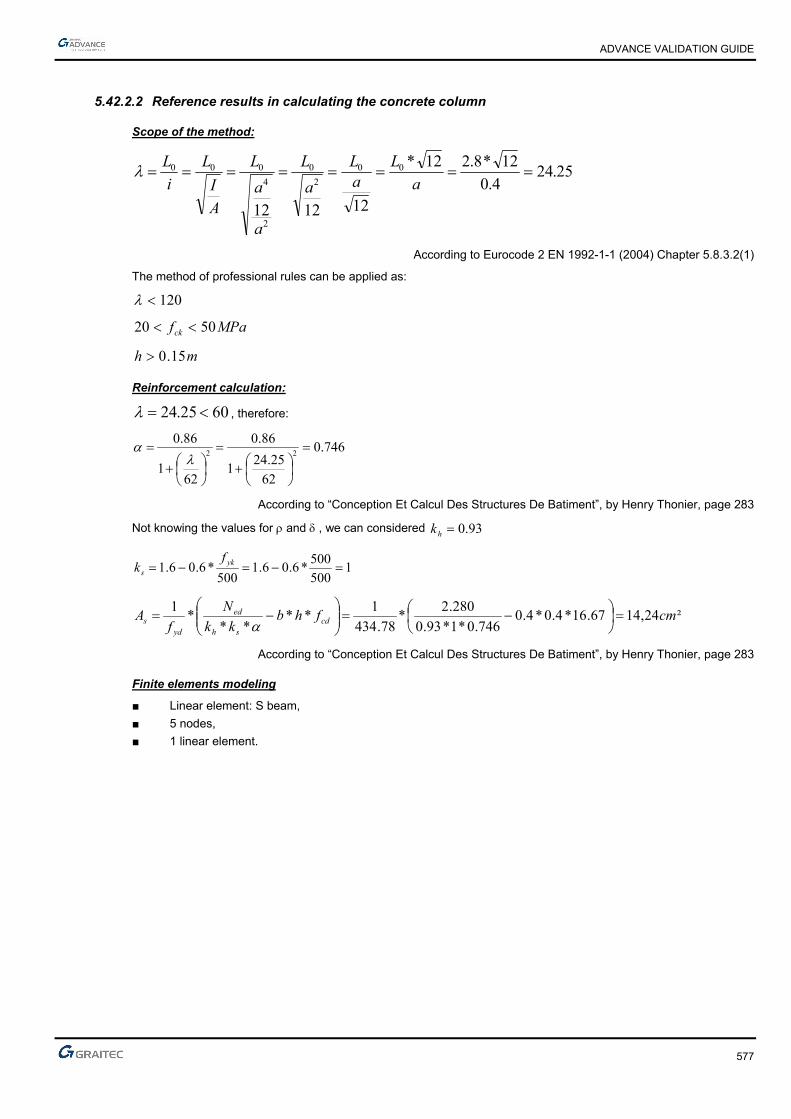
ADVANCE VALIDATION GUIDE
577
5.42.2.2 Reference results in calculating the concrete column
Scope of the method:
25.244.0
12*8.212*
121212
00
2
0
2
4
000 a
LaL
a
L
a
a
L
A
I
L
i
L
According to Eurocode 2 EN 1992-1-1 (2004) Chapter 5.8.3.2(1)
The method of professional rules can be applied as:
120
MPafck 5020
mh 15.0
Reinforcement calculation:
6025.24 , therefore:
746.0
62
25.241
86.0
621
86.022
According to “Conception Et Calcul Des Structures De Batiment”, by Henry Thonier, page 283
Not knowing the values for and , we can considered 93.0hk
1500
500*6.06.1
500*6.06.1 yk
s
fk
²24,1467.16*4.0*4.0746.0*1*93.0
280.2*
78.434
1**
***
1cmfhb
kk
N
fA cd
sh
ed
yds
According to “Conception Et Calcul Des Structures De Batiment”, by Henry Thonier, page 283
Finite elements modeling
■ Linear element: S beam,
■ 5 nodes,
■ 1 linear element.
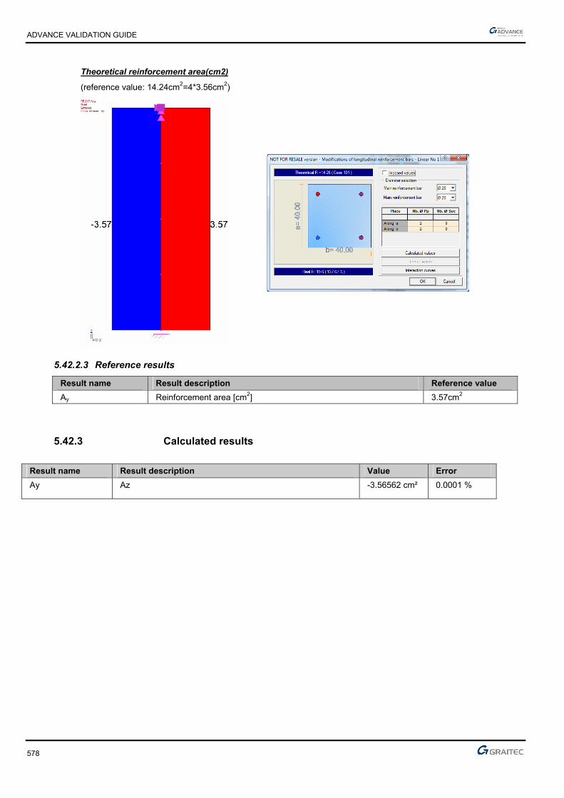
ADVANCE VALIDATION GUIDE
578
Theoretical reinforcement area(cm2)
(reference value: 14.24cm2=4*3.56cm2)
5.42.2.3 Reference results
Result name Result description Reference value
Ay Reinforcement area [cm2] 3.57cm2
5.42.3 Calculated results
Result name Result description Value Error
Ay Az -3.56562 cm² 0.0001 %

ADVANCE VALIDATION GUIDE
579
5.43 EC2 Test 38: Verifying a rectangular concrete column using the simplified method – Professional rules - Bilinear stress-strain diagram (Class XC1)
Test ID: 5127
Test status: Passed
5.43.1 Description
Verifies a rectangular cross section concrete C25/30 column using the simplified method –Professional rules - Bilinear stress-strain diagram (Class XC1).
The column is considered connected to the ground by an articulated connection (all the translations are blocked). At the top part, the translations along X and Y axis are blocked and the rotation along the Z axis is also blocked.
5.43.2 Background
Simplified Method
Verifies the adequacy of a rectangular cross section made from concrete C25/30.
5.43.2.1 Model description
■ Reference: Guide de validation Eurocode 2 EN 1992-1-1-2002;
■ Analysis type: static linear (plane problem);
■ Element type: linear.
The following load cases and load combination are used:
■ Loadings from the structure:
► 800kN axial force
► The self-weight is neglected
■ Concrete cover 5cm
■ Concrete C25/30
■ Steel reinforcement S500B
■ Relative humidity RH=50%
■ Buckling length L0=6.50m
Units
Metric System
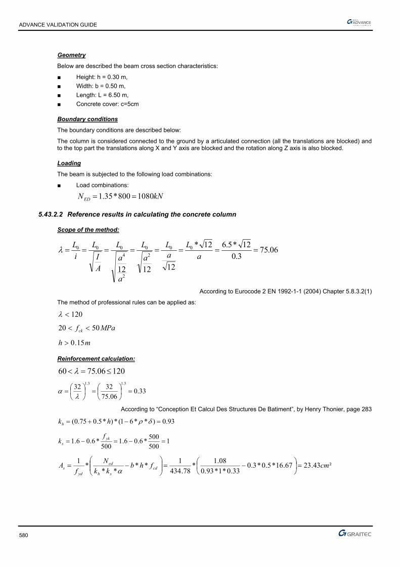
ADVANCE VALIDATION GUIDE
580
Geometry
Below are described the beam cross section characteristics:
■ Height: h = 0.30 m,
■ Width: b = 0.50 m,
■ Length: L = 6.50 m,
■ Concrete cover: c=5cm
Boundary conditions
The boundary conditions are described below:
The column is considered connected to the ground by a articulated connection (all the translations are blocked) and to the top part the translations along X and Y axis are blocked and the rotation along Z axis is also blocked.
Loading
The beam is subjected to the following load combinations:
■ Load combinations:
kNNED 1080800*35.1
5.43.2.2 Reference results in calculating the concrete column
Scope of the method:
06.753.0
12*5.612*
121212
00
2
0
2
4
000 a
LaL
a
L
a
a
L
A
I
L
i
L
According to Eurocode 2 EN 1992-1-1 (2004) Chapter 5.8.3.2(1)
The method of professional rules can be applied as:
120
MPafck 5020
mh 15.0
Reinforcement calculation:
12006.7560
33.006.75
32323.13.1
According to “Conception Et Calcul Des Structures De Batiment”, by Henry Thonier, page 283
93.0)**61(*)*5.075.0( hkh
1500
500*6.06.1
500*6.06.1 yk
s
fk
²43.2367.16*5.0*3.033.0*1*93.0
08.1*
78.434
1**
***
1cmfhb
kk
N
fA cd
sh
ed
yds
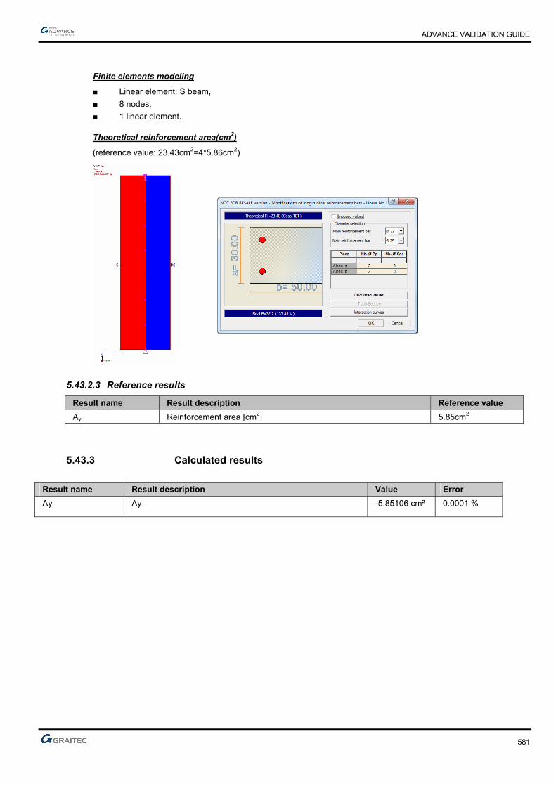
ADVANCE VALIDATION GUIDE
581
Finite elements modeling
■ Linear element: S beam,
■ 8 nodes,
■ 1 linear element.
Theoretical reinforcement area(cm2)
(reference value: 23.43cm2=4*5.86cm2)
5.43.2.3 Reference results
Result name Result description Reference value
Ay Reinforcement area [cm2] 5.85cm2
5.43.3 Calculated results
Result name Result description Value Error
Ay Ay -5.85106 cm² 0.0001 %
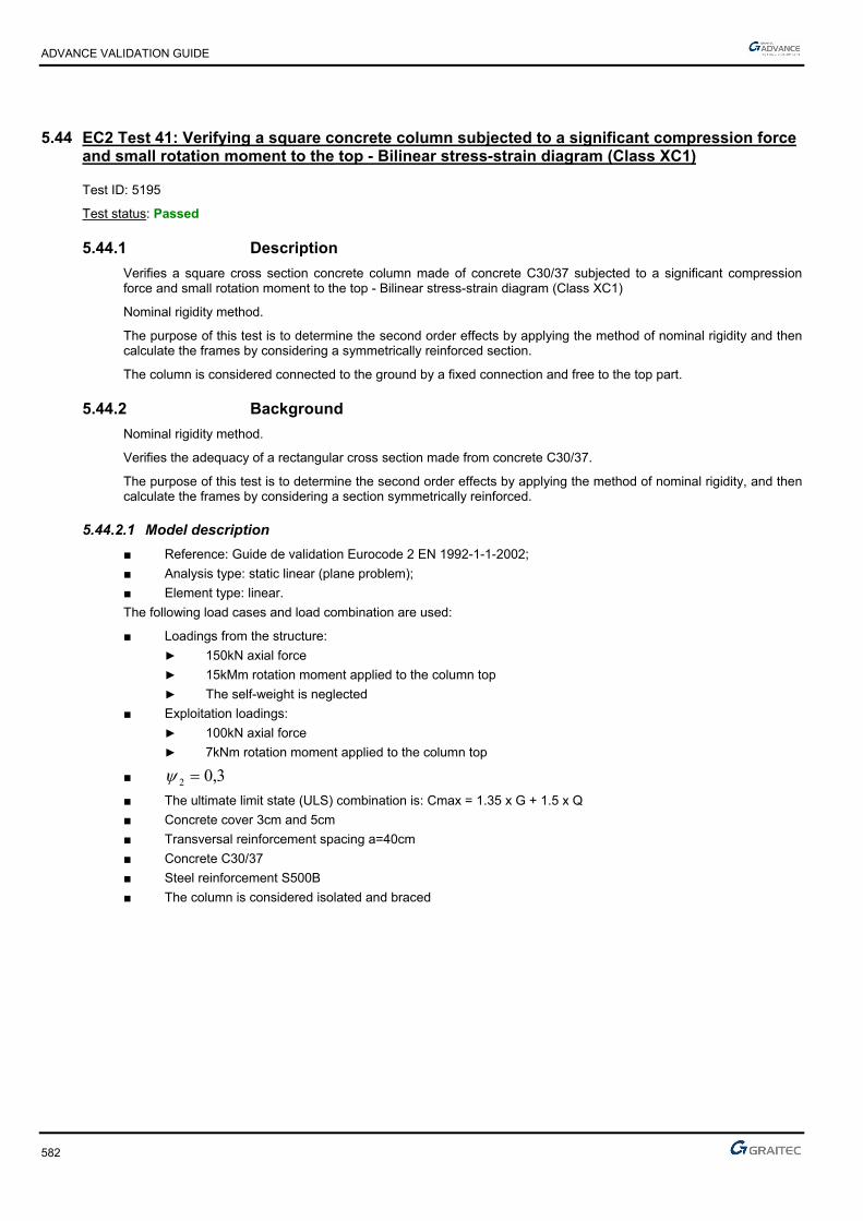
ADVANCE VALIDATION GUIDE
582
5.44 EC2 Test 41: Verifying a square concrete column subjected to a significant compression force and small rotation moment to the top - Bilinear stress-strain diagram (Class XC1)
Test ID: 5195
Test status: Passed
5.44.1 Description
Verifies a square cross section concrete column made of concrete C30/37 subjected to a significant compression force and small rotation moment to the top - Bilinear stress-strain diagram (Class XC1)
Nominal rigidity method.
The purpose of this test is to determine the second order effects by applying the method of nominal rigidity and then calculate the frames by considering a symmetrically reinforced section.
The column is considered connected to the ground by a fixed connection and free to the top part.
5.44.2 Background
Nominal rigidity method.
Verifies the adequacy of a rectangular cross section made from concrete C30/37.
The purpose of this test is to determine the second order effects by applying the method of nominal rigidity, and then calculate the frames by considering a section symmetrically reinforced.
5.44.2.1 Model description
■ Reference: Guide de validation Eurocode 2 EN 1992-1-1-2002;
■ Analysis type: static linear (plane problem);
■ Element type: linear.
The following load cases and load combination are used:
■ Loadings from the structure:
► 150kN axial force
► 15kMm rotation moment applied to the column top
► The self-weight is neglected
■ Exploitation loadings:
► 100kN axial force
► 7kNm rotation moment applied to the column top
■ 3,02
■ The ultimate limit state (ULS) combination is: Cmax = 1.35 x G + 1.5 x Q
■ Concrete cover 3cm and 5cm
■ Transversal reinforcement spacing a=40cm
■ Concrete C30/37
■ Steel reinforcement S500B
■ The column is considered isolated and braced

ADVANCE VALIDATION GUIDE
583
Units
Metric System
Geometry
Beam cross section characteristics:
■ Height: h = 0.50 m,
■ Width: b = 0.50 m,
■ Length: L = 5.80 m,
■ Concrete cover: c = 5cm
Boundary conditions
The boundary conditions are described below:
The column is considered connected to the ground by a fixed connection and free to the top part.
Loading
The beam is subjected to the following load combinations:
■ Load combinations:
The ultimate limit state (ULS) combination is:
NEd = 1.35*150+1.50*100 = 352.50kN = 0.035MN
MEd = 1.35*15+1.50*7 = 30.75kNm = 0.03075MNm
■ m..
.
N
Me
Ed
Ed 08703530
0370500

ADVANCE VALIDATION GUIDE
584
5.44.2.2 Reference results in calculating the concrete column
Geometric characteristics of the column:
The column has a fixed connection on the bottom end and is free on the top end, therefore, the buckling length is considered to be:
mll 60.11*20
According to Eurocode 2 – EN 1992-1-1 -2004; Chapter 5.8.3.2(1); Figure 5.7 b)
Calculating the slenderness of the column:
37.8050.0
60.11*32*32 0 a
l
Effective creep coefficient calculation:
The creep coefficient is calculated using the next formula:
Ed
EQPef M
Mt ., 0
According to Eurocode 2 – EN 1992-1-1 -2004; Chapter 5.8.4(2)
Where:
0,t creep coefficient
EQPM serviceability firs order moment under quasi-permanent load combination
EdM ULS first order moment (including the geometric imperfections)
First order eccentricity evaluation:
ieee 01
mei 03.0
The first order moment provided by the quasi-permanent loads:
meN
Meee i
Eqp
Eqpi 125.030.0
100*30.0150
7*30.015
0
001
kNNEqp 180100*30.01501
MNmkNmeNM EqpEqp 0225.050.22125.0*180* 111
The first order ULS moment is defined latter in this example:
MNmMEd 041.01
The creep coefficient 0,t is defined as follows:
)(*)(*),( 00 tft cmRH
72.2830
8.168.16)(
cm
cmf
f
488.0281.0
1
1.0
1)(
20.020.00
0
t
t (for t0= 28 days concrete age).

ADVANCE VALIDATION GUIDE
585
213
0
***1.0100
11
h
RH
RH
MPafcm 35 therefore: 944.038
35357.07.0
1
cmf and 984.0
38
35352.02.0
2
cmf
72.1984.0*944.0*250*1.0
100
501
1250500500*2
500*500*2*230
RHmm
u
Ach
28.2488.0*72.2*72.1)(*)(*),( 00 tft cmRH
The effective creep coefficient calculation:
25.1041.0
0225.0*28.2*, 0
Ed
EQPef M
Mt
According to Eurocode 2 – EN 1992-1-1 -2004; Chapter 5.8.4(2)
The second order effects; The buckling calculation:
For an isolated column, the slenderness limit verification is done using the next formula:
n
CBA ***20lim
According to Eurocode 2 – EN 1992-1-1 -2004; Chapter 5.8.3.1(1)
Where:
071.020*²50.0
353.0
*
cdc
Ed
fA
Nn
80.025.1*2.01
1
*2,01
1
ef
A
1.1*21 B because the reinforcement ratio in not yet known
70.07,1 mrC because the ratio of the first order moment is not known
24.46071.0
7.0*1.1*80.0*20lim
24.4637.80 lim
Therefore, the second order effects must be taken into account.
Calculation of the eccentricities and solicitations corrected for ULS:
The stresses for the ULS load combination are:
■ NEd= 1.35*150 + 1.50*100= 352.5kN = 0,3525 MN
■ MEd= 1.35*15 + 1.50*7= 352.5kN= 0.03075MNm
Therefore, we must calculate:
■ The eccentricity of the first order ULS moment, due to the stresses applied
■ The additional eccentricity considered for the geometrical imperfections

ADVANCE VALIDATION GUIDE
586
Initial eccentricity:
mN
Me
Ed
Ed 087.0353.0
03075.00
Additional eccentricity:
ml
ei 03.0400
6.11
4000
The first order eccentricity: stresses correction:
The forces correction, used for the combined flexural calculations:
MNNEd 353.0
meee i 117.001
MNmNeM EdEd 041.0353.0*117.0*1
0*eNM Ed
mmmm
mmmmmm
hmm
e 207.16
20max
30
50020
max30
20max0
According to Eurocode 2 – EN 1992-1-1 -2004; Chapter 6.1.(4)
Reinforcement calculation in the first order situation:
To apply the nominal rigidity method, we need an initial reinforcement area to start from. For this, the concrete section will be sized considering only the first order effect.
The Advance Design calculation is different: it is iterating as many time as necessary starting from the minimum percentage area.
The reinforcement will be determined using a compound bending with compressive stress. The determined solicitations were calculated from the center of gravity of the concrete section alone. Those stresses must be reduced to the centroid of tensioned steel:
MNmh
dNMM Gua 112.02
50.045.0*353.0041.0)
2(*0
Verification about the partially compressed section:
494,0)45,0
50,0*4,01(*
45,0
50,0*8,0)*4,01(**8,0
d
h
d
hBC
055.020*²45.0*50.0
112.0
*²*
cdw
uacu fdb
M
494.0055.0 BCcu therefore the section is partially compressed

ADVANCE VALIDATION GUIDE
587
The calculation for the tensioned steel in pure bending:
055.0cu
071,0)055,0*21(1*25,1 u
mdz uc 437,0)071,0*4,01(*45,0)*4,01(*
²89,578,434*437,0
112,0
*cm
fz
MA
ydc
ua
The calculation for the compressed steel in bending:
For the compound bending:
24 23.278.434
353.010*89.5 cm
F
NAA
yd
The minimum column percentage reinforcement must be considered:
²81.078.434
353.0*10.0*10,0min, cm
F
NA
yd
Eds
Therefore, a 5cm2 reinforcement area will be considered.

ADVANCE VALIDATION GUIDE
588
5.44.2.3 Calculation of the second order effects:
Estimation of the nominal rigidity:
It is estimated the nominal rigidity of a post or frame member from the following formula:
sssccdc IEKIEKEI ****
Where:
2.1cm
cd
EE
MpaMpaff ckcm 388
Mpaf
E cmcm 57.32836
10
38*22000
10*22000
3.03.0
MpaE
E cmcd 27364
2.1
32837
2.1
4343
10.208,512
50.0
12
*m
hbIc
inertia of the concrete section only
MpaEs 200000
sI : Inertia
002.050.0*50.0
10.5 4
c
s
A
A
01.0002.0 c
s
A
A
22.120
30
201 ckfk
071.020*²50.0
353.0
*
cdc
Ed
fA
Nn
20.00336.0170
37.80*071.0
170*2
nk
45242
10.205.02
50.0*
2
10*5*2
2*
2*2 mc
hAI ss
1sK and 018.025.11
0336.0*22.1
1
* 21
ef
c
kkK
Therefore:
²56.610*2*200000*110*208,5*27364*018.0 53 MNmEI

ADVANCE VALIDATION GUIDE
589
Stress correction:
The total moment, including second order effects, is defined as a value plus the moment of the first order:
11*0
Ed
BEdEd
N
NMM
MNmM Ed 041.00 (moment of first order (ULS) taking into account geometric imperfections)
MNNEd 353.0 (normal force acting at ULS).
In addition:
0
²
c
and 80 c because the moment is constant (no horizontal force at the top of post).
234.18
²
MNl
EINB 48.0
²60.11
56.6*²*² 2
0
It was therefore a moment of 2nd order which is:
MNmMEd 182.01
353.0
48.0234.1
1*041.0
There is thus a second order moment of 0.182MNm

ADVANCE VALIDATION GUIDE
590
Calculation of the flexural combined reinforcement
The theoretical reinforcement will be determined by the following diagram:
MNmMEd 182.0
MNNEd 353.0
The input parameters of the diagram are:
073.020*50.0*50.0
182.0
** 22
cd
Ed
fhb
M
071.020*5.0*5.0
353.0
**
cd
Ed
fhb
N
Therefore:
11.0
The reinforcement area will be:
22
65.1278.434
20*50.0*11.0***cm
f
fhbA
yd
cds
This means a total of 12.65cm2
The initial calculations must be repeated by increasing the section; a 6cm2 reinforcement section will be considered.
Additional iteration:
One more iteration by considering an initial section of 6.5cm ²

ADVANCE VALIDATION GUIDE
591
Estimation of the nominal rigidity:
sssccdc IEKIEKEI ****
Where:
2.1cm
cd
EE
MpaMpaff ckcm 388
Mpaf
E cmcm 57.32836
10
38*22000
10*22000
3.03.0
MpaE
E cmcd 27364
2.1
32837
2.1
4343
10.208,512
50.0
12
*m
hbIc
considering only the concrete section only
MpaEs 200000
sI : Inertia
0026.050.0*50.0
10*5.6 4
c
s
A
A
01.0002.0 c
s
A
A
22.120
30
201 ckfk
071.020*²50.0
353.0
*
cdc
Ed
fA
Nn
20.00336.0170
37.80*071.0
170*2
nk
45242
106.205.02
50.0
2
10*5.6*2
2*
2*2 mc
hAI ss
1sK and 018.0
25.11
0336.0*22.1
1
* 21
ef
c
kkK
Therefore:
²78.710*6.2*200000*110*208,5*27364*018.0 53 MNmEI
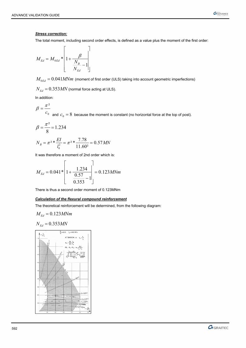
ADVANCE VALIDATION GUIDE
592
Stress correction:
The total moment, including second order effects, is defined as a value plus the moment of the first order:
11*0
Ed
BEdEd
N
NMM
MNmM Ed 041.00 (moment of first order (ULS) taking into account geometric imperfections)
MNNEd 353.0 (normal force acting at ULS).
In addition:
0
²
c
and 80 c because the moment is constant (no horizontal force at the top of post).
234.18
²
MNl
EINB 57.0
²60.11
78.7*²*² 2
0
It was therefore a moment of 2nd order which is:
MNmMEd 123.01
353.0
57.0234.1
1*041.0
There is thus a second order moment of 0.123MNm
Calculation of the flexural compound reinforcement
The theoretical reinforcement will be determined, from the following diagram:
MNmMEd 123.0
MNNEd 353.0

ADVANCE VALIDATION GUIDE
593
The input parameters of the diagram are:
049.020*50.0*50.0
123.0
** 22 cd
Ed
fhb
M
071.020*5.0*5.0
353.0**
cd
Ed
fhbN
Therefore:
05.0
The reinforcement area will be:
22
75.578.434
20*50.0*05.0***cm
f
fhbA
yd
cds
This means a total of 5.75cm2
Finite elements modeling
■ Linear element: S beam,
■ 7 nodes,
■ 1 linear element.
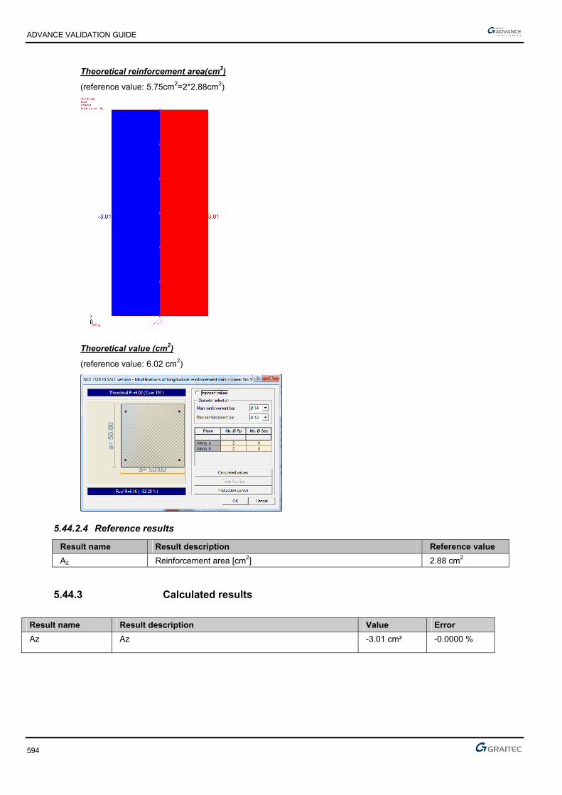
ADVANCE VALIDATION GUIDE
594
Theoretical reinforcement area(cm2)
(reference value: 5.75cm2=2*2.88cm2)
Theoretical value (cm2)
(reference value: 6.02 cm2)
5.44.2.4 Reference results
Result name Result description Reference value
Az Reinforcement area [cm2] 2.88 cm2
5.44.3 Calculated results
Result name Result description Value Error
Az Az -3.01 cm² -0.0000 %

ADVANCE VALIDATION GUIDE
595
5.45 EC2 Test 42: Verifying a square concrete column subjected to a significant rotation moment and small compression force to the top with Nominal Curvature Method - Bilinear stress-strain diagram (Class XC1)
Test ID: 5205
Test status: Passed
5.45.1 Description
Verifies a square cross section column made of concrete C30/37 subjected to a significant rotation moment and small compression force to the top with Nominal Curvature Method - Bilinear stress-strain diagram (Class XC1).
The verification of the axial stresses and rotation moment, applied on top, at ultimate limit state is performed.
Nominal curvature method.
The purpose of this test is to determine the second order effects by applying the method of nominal rigidity, and then calculate the frames by considering a section symmetrically reinforced.
The column is considered connected to the ground by a fixed connection and free to the top part.
5.45.2 Background
Nominal curvature method.
Verifies the adequacy of a square cross section made from concrete C30/37.
The purpose of this test is to determine the second order effects by applying the method of nominal rigidity, and then calculate the frames by considering a section symmetrically reinforced.
5.45.2.1 Model description
■ Reference: Guide de validation Eurocode 2 EN 1992-1-1-2002;
■ Analysis type: static linear (plane problem);
■ Element type: linear.
The following load cases and load combination are used:
■ Loadings from the structure:
► 15kN axial force
► 150kMm rotation moment applied to the column top
► The self-weight is neglected
■ Exploitation loadings:
► 7kN axial force
► 100kNm rotation moment applied to the column top
■ 3,02
■ The ultimate limit state (ULS) combination is: Cmax = 1.35 x G + 1.5 x Q
■ Concrete cover 3cm and 5cm
■ Transversal reinforcement spacing a=40cm
■ Concrete C30/37
■ Steel reinforcement S500B
■ The column is considered isolated and braced
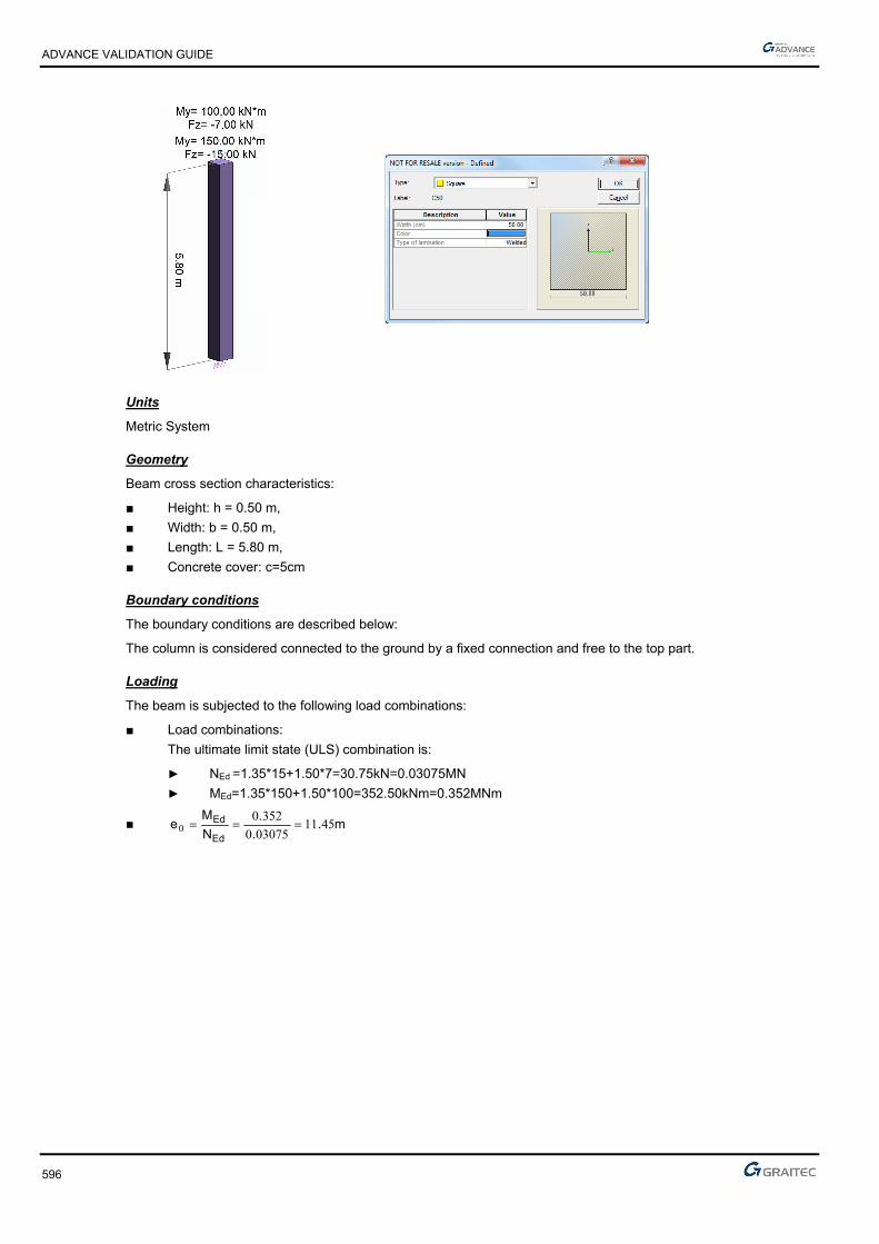
ADVANCE VALIDATION GUIDE
596
Units
Metric System
Geometry
Beam cross section characteristics:
■ Height: h = 0.50 m,
■ Width: b = 0.50 m,
■ Length: L = 5.80 m,
■ Concrete cover: c=5cm
Boundary conditions
The boundary conditions are described below:
The column is considered connected to the ground by a fixed connection and free to the top part.
Loading
The beam is subjected to the following load combinations:
■ Load combinations:
The ultimate limit state (ULS) combination is:
► NEd =1.35*15+1.50*7=30.75kN=0.03075MN
► MEd=1.35*150+1.50*100=352.50kNm=0.352MNm
■ m..
.
N
Me
Ed
Ed 4511030750
35200

ADVANCE VALIDATION GUIDE
597
5.45.2.2 Reference results in calculating the concrete column
Geometric characteristics of the column:
The column has a fixed connection on the bottom end and is free on the top end, therefore, the buckling length is considered to be:
mll 60.11*20
According to Eurocode 2 – EN 1992-1-1 -2004; Chapter 5.8.3.2(1); Figure 5.7 b)
Calculating the slenderness of the column:
37.8050.0
60.11*32*32 0 a
l
Effective creep coefficient calculation:
The creep coefficient is calculated using the next formula:
Ed
EQPef M
Mt ., 0
According to Eurocode 2 – EN 1992-1-1 -2004; Chapter 5.8.4(2)
Where:
0,t creep coefficient
EQPM serviceability firs order moment under quasi-permanent load combination
EdM ULS first order moment (including the geometric imperfections)
First order eccentricity evaluation:
ieee 01
mei 03.0
The first order moment provided by the quasi-permanent loads:
meN
Meee i
Eqp
Eqpi 56.1030.0
7*30.015
100*30.0150
0
001
kNNEqp 10.177*30.0151
MNmkNmeNM EqpEqp 181.058.18056.10*10.17* 111
The first order ULS moment is defined latter in this example:
MNmMEd 3523.01
The creep coefficient 0,t is defined as follows:
)(*)(*),( 00 tft cmRH
72.2830
8.168.16)(
cm
cmf
f
488.0281.0
1
1.0
1)(
20.020.00
0
t
t (for t0= 28 days concrete age).
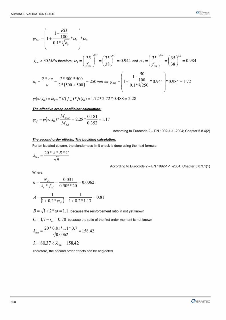
ADVANCE VALIDATION GUIDE
598
213
0
***1.0100
11
h
RH
RH
MPafcm 35 therefore: 944.038
35357.07.0
1
cmf and 984.0
38
35352.02.0
2
cmf
72.1984.0*944.0*250*1.0
100
501
1250500500*2
500*500*2*230
RHmm
u
Ach
28.2488.0*72.2*72.1)(*)(*),( 00 tft cmRH
The effective creep coefficient calculation:
17.1352.0
181.0*28.2*, 0
Ed
EQPef M
Mt
According to Eurocode 2 – EN 1992-1-1 -2004; Chapter 5.8.4(2)
The second order effects; The buckling calculation:
For an isolated column, the slenderness limit check is done using the next formula:
n
CBA ***20lim
According to Eurocode 2 – EN 1992-1-1 -2004; Chapter 5.8.3.1(1)
Where:
0062.020*²50.0
031.0
*
cdc
Ed
fA
Nn
81.017.1*2.01
1
*2,01
1
ef
A
1.1*21 B because the reinforcement ratio in not yet known
70.07,1 mrC because the ratio of the first order moment is not known
42.1580062.0
7.0*1.1*81.0*20lim
42.15837.80 lim
Therefore, the second order effects can be neglected.
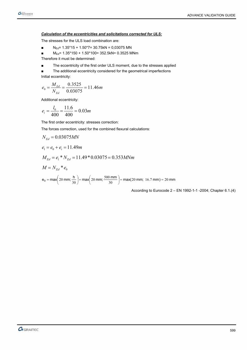
ADVANCE VALIDATION GUIDE
599
Calculation of the eccentricities and solicitations corrected for ULS:
The stresses for the ULS load combination are:
■ NEd= 1.35*15 + 1.50*7= 30.75kN = 0,03075 MN
■ MEd= 1.35*150 + 1.50*100= 352.5kN= 0.3525 MNm
Therefore it must be determined:
■ The eccentricity of the first order ULS moment, due to the stresses applied
■ The additional eccentricity considered for the geometrical imperfections
Initial eccentricity:
mN
Me
Ed
Ed 46.1103075.0
3525.00
Additional eccentricity:
ml
ei 03.0400
6.11
4000
The first order eccentricity: stresses correction:
The forces correction, used for the combined flexural calculations:
MNNEd 03075.0
meee i 49.1101
MNmNeM EdEd 353.003075.0*49.11*1
0*eNM Ed
mm)mm.;mmmax(mm
;mmmaxh
;mmmaxe 207162030
50020
30200
According to Eurocode 2 – EN 1992-1-1 -2004; Chapter 6.1.(4)

ADVANCE VALIDATION GUIDE
600
Reinforcement calculation in the first order situation:
The theoretical reinforcement will be determined by the following diagram:
The input parameters of the diagram are:
141.020*50.0*50.0
353.0
** 22 cd
Ed
fhb
M
00615.020*5.0*5.0
03075.0**
cd
Ed
fhbN
Therefore:
35.0
The reinforcement area will be:
22
25.4078.434
20*50.0*cmAs
which means 20.13cm2 per face.
The total area will be 40.25cm2.

ADVANCE VALIDATION GUIDE
601
The nominal curvature methods (second order effect):
The curvature calculation:
Considering a reinforcement of 40.25cm² (considered symmetric), one can determine the curvature from the following formula:
0
1**
1
rKK
r r
According to Eurocode 2 – EN 1992-1-1(2004): Chapter 5.8.8.3(1)
1
0
0107.045.0*45,0
1000
78.434
)*45,0()*45,0(
1 md
E
f
drs
yd
yd
Kr is the correction coefficient depending of the normal force:
1
balu
ur nn
nnK
According to Eurocode 2 – EN 1992-1-1(2004): Chapter 5.8.8.3(3)
00615.020*²50.0
03075.0
*
cdc
Ed
fA
Nn
350.020*²50.0
78.434*10*25.40
*
* 4
cdc
yds
fA
fA
350.1350.011 un
4,0baln
41.140.0350.1
00615.0350.1
rK
Condition: 1rK , therefore it will be considered: 1rK
K creep coefficient: 1*1 efK
According to Eurocode 2 – EN 1992-1-1(2004): Chapter 5.8.8.3(4)
therefore
Calculation moment:
The moment of calculation is estimated from the formula:
20 MMM EdEd
Where:
EdM 0 is moment of the first order including geometric imperfections.

ADVANCE VALIDATION GUIDE
602
2M is nominal moment of second order.
The 2nd order moment is calculated from the curvature:
22 *eNM Ed
mc
l
re 144.0
10
²60.11*0107.0*
1 20
2
MNmeNM Ed 00443.0144.0*03075.0* 22
MNmMMM EdEd 357.000443.0353.020
The reinforcement must be sized considering the demands of the second degree effects, as follows:
MNNEd 03075.0
MNmMEd 357.0
Reinforcement calculation according the second order effects:
The interaction diagram will be used.
The input parameters in the diagram are:
35.0 will be obtained, which gives: ²25.40078.434
20*²50.0*35.0***cm
f
fhbA
yd
cds
Meaning a 20.13 cm2 per side (which confirms the initial section)
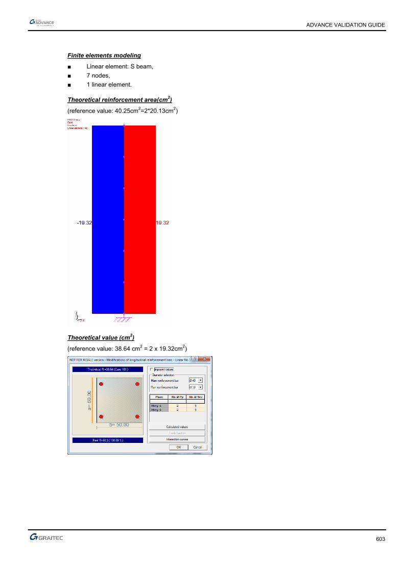
ADVANCE VALIDATION GUIDE
603
Finite elements modeling
■ Linear element: S beam,
■ 7 nodes,
■ 1 linear element.
Theoretical reinforcement area(cm2)
(reference value: 40.25cm2=2*20.13cm2)
Theoretical value (cm2)
(reference value: 38.64 cm2 = 2 x 19.32cm2)
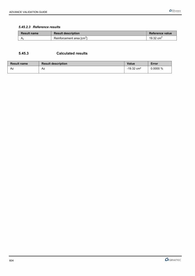
ADVANCE VALIDATION GUIDE
604
5.45.2.3 Reference results
Result name Result description Reference value
Az Reinforcement area [cm2] 19.32 cm2
5.45.3 Calculated results
Result name Result description Value Error
Az Az -19.32 cm² 0.0000 %

ADVANCE VALIDATION GUIDE
605
5.46 EC2 Test36: Verifying a rectangular concrete column using the method based on nominal curvature- Bilinear stress-strain diagram (Class XC1)
Test ID: 5125
Test status: Passed
5.46.1 Description
Verifying a rectangular concrete column using the method based on nominal curvature - Bilinear stress-strain diagram (Class XC1)
Verifies the adequacy of a rectangular cross section column made from concrete C30/37.
Method based on nominal curvature
The purpose of this test is to determine the second order effects by applying the method of nominal curvature, and then calculate the frames by considering a section symmetrically reinforced.
The column is considered connected to the ground by an articulated connection (all the translations are blocked and all the rotations are permitted) and to the top part the translations along X and Y axis are blocked and the rotation along Z axis is also blocked.
This example is provided by the “Calcul des Structures en beton” book, by Jean-Marie Paille, edition Eyrolles.
5.46.2 Background
Method based on nominal curvature
Verifies the adequacy of a rectangular cross section made from concrete C30/37.
The purpose of this test is to determine the second order effects by applying the method of nominal curvature, and then calculate the frames by considering a section symmetrically reinforced.
5.46.2.1 Model description
■ Reference: Guide de validation Eurocode 2 EN 1992-1-1-2002;
■ Analysis type: static linear (plane problem);
■ Element type: linear.
The following load cases and load combination are used:
■ Loadings from the structure:
► 400kN axial force
► The self-weight is neglected
■ Exploitation loadings:
► 300kN axial force
► The quasi permanent coefficient 3,02
■ Wind loads:
► 250kN axial force
► The wind loads are applied horizontally on the middle of the column to the wider face (against the positive sense of the Y local axis)
► The quasi permanent coefficients 10 and 02
■ Concrete cover 5cm
■ Concrete C30/37
■ Steel reinforcement S500B
■ Relative humidity RH=50%
■ Concrete age t0=30days
■ The reinforcement is set to 8HA16 (16.08cm2)

ADVANCE VALIDATION GUIDE
606
Units
Metric System
Geometry
Below are described the beam cross section characteristics:
■ Height: h = 0.35 m,
■ Width: b = 0.60 m,
■ Length: L = 5.00 m,
■ Concrete cover: c = 5 cm
Boundary conditions
The boundary conditions are described below:
The column is considered connected to the ground by a articulated connection (all the translations are blocked and all the rotations are permitted) and to the top part the translations along X and Y axis are blocked and the rotation along Z axis is also blocked.
Loading
The beam is subjected to the following load combinations:
■ Load combinations:
MNNED 99.03.0*5.14.0*35.1
cmN
Me
u
u 00
cm;cmmaxl
;cmmaxei 2400
5002
4002 0
First order eccentricity: m.cmeee i 020201

ADVANCE VALIDATION GUIDE
607
5.46.2.2 Reference results in calculating the concrete column
Geometric characteristics of the column:
The column has a fixed connection on the bottom end and is free on the top end, therefore, the buckling length is considered to be:
mll 50
According to Eurocode 2 – EN 1992-1-1 -2004; Chapter 5.8.3.2(1); Figure 5.7 b)
Calculating the slenderness of the column:
5.4935.0
5*32*32 0 a
l
Effective creep coefficient calculation:
The creep coefficient is determined by the next formula:
Ed
EQPef M
Mt ., 0
According to Eurocode 2 – EN 1992-1-1 -2004; Chapter 5.8.4(2)
Where:
0,t creep coefficient
EQPM serviceability firs order moment under quasi-permanent load combination
The EQPM value is calculated using the
WQGMEQP *03.0
MNmeNM qpEqp 0098.002.0*)3.0*3.04.0(* 10
EdM ULS first order moment (including the geometric imperfections)
The EDM 0 value is calculated using the WQGMoED *5.1*5.135.1
MNmL
HeNM WedEqp 48855.04
5*25.0*5.102.0*99.0
4**5.1* 10
The moment report becomes:
02.048855.0
0098.0
0
0 Ed
Eqp
M
M
The creep coefficient 0,t is:
)(*)(*),( 00 tft cmRH
MPaf
fcm
cm 73.2830
8.168.16)(
482.0301.0
1
1.0
1)(
20.020.00
0
t
t (for t0= 30 days concrete age).

ADVANCE VALIDATION GUIDE
608
213
0
***1.0100
11
h
RH
RH
RH = relative humidity; RH = 50%
Where 121 if MPafcm 35 if not
7.0
1
35
cmf and
2.0
2
35
cmf
mmu
Ach 221
600350*2
600*350*2*20
MPaMPafcm 3538 therefore 944.038
35357.07.0
1
cmf and
984.038
35352.02.0
2
cmf
752.1984.0*944.0*221*1.0
100
501
1***1.0100
11
3213
0
h
RH
RH
30.2482.0*73.2*752.1)(*)(*),( 00 tft cmRH
The effective creep coefficient calculation:
046.002.0*30.2*, 0 Ed
EQPef M
Mt
According to Eurocode 2 – EN 1992-1-1 -2004; Chapter 5.8.4(2)
046.1046.011 ef
The necessity of buckling calculation (second order effect):
The M2 moment is calculated from the curvature formula: 22 * eNM Ed
c
l
re
20
2 *1
l0 is the buckling length: l0=l=5m
“c” is a factor depending on the curvature distribution. Because the cross section is constant, c = 10.
0
1**
1
rKK
r r
According to Eurocode 2 – EN 1992-1-1(2004): Chapter 5.8.8.3(1)
).45,0(
1
0 dryd
and
1000
1739.2
200000
78.434
s
ydyd E
f

ADVANCE VALIDATION GUIDE
609
1
0
0161.0)30.0*45,0(
1000
1739.2
)*45,0(
1 mdr
yd
Kr is the correction coefficient depending of the normal force:
1
balu
ur nn
nnK
According to Eurocode 2 – EN 1992-1-1(2004): Chapter 5.8.8.3(3)
236.020*35.0*6.0
99.0
*
cdc
Ed
fA
Nn
1un
166.020*35.0*6.0
78.434*10*08.16 4
cdc
yds
fA
fA
166.1166.0.11 un
4,0baln
214.14.0166.1
236.0166.1
balu
ur nn
nnK
Condition: 1rK , therefore it will be considered: 1rK
K creep coefficient: 1*1 efK
According to Eurocode 2 – EN 1992-1-1(2004): Chapter 5.8.8.3(4)
15020035,0
ckf
5.4935.0
125120 h
l
17.0150
5.49
200
3035.0
15020035,0
ckf
008.1046.0*17.01*1 efK
Therefore:
0162.00161.0*008.1*11
**1
0
r
KKr r
mc
l
re 04057.0
10
²5*0162.0*
1 20
2
MNmeNM Ed 04017.004057.0*990.0* 22
MNmMMM EdEd 5287.004017.048855.020
The frames must be sized considering the demands of the second degree effects, as follows:
MNNEd 990.0

ADVANCE VALIDATION GUIDE
610
MNmM Ed 5287.0
Reinforcement calculation according the second order effects:
The calculations are made using the following values:
MNNEd 990.0
MNmM Ed 5287.0
The calculations resulted in 38.02cm2 tensioned reinforcement and a 20cm2 compressed reinforcement, meaning a total of 58.02cm2 reinforcement area.
Buckling checking:
The calculation is performed considering the reinforcement found previously (58.02cm2):
Curvature calculation:
The reinforcement area has an influence only over the Kr parameter:
1
0
0161.01 mr
1
balu
ur nn
nnK
112.0n
60.020*35.0*60.0
78.434*10*02,58
*
* 4
cdc
yds
fA
fA
60.160.011 un
4,0baln
1124.140.060.1
112.060.1
rr KK
1K the creep coefficient 1.1 efK
Therefore the curvature becomes:
1
0
0161.01
**1 m
rKK
r r
Considering this result, the same curvature is obtained, which means that the second order moment is the same. The reinforcement section is correctly chosen.
Finite elements modeling
■ Linear element: S beam,
■ 5 nodes,
■ 1 linear element.

ADVANCE VALIDATION GUIDE
611
Theoretical reinforcement area (cm2)
(reference value: 38.01cm2)
Theoretical value (cm2)
(reference value: 76.02 cm2)
5.46.2.3 Reference results
Result name Result description Reference value
Ay Reinforcement area [cm2] 38.02cm2
5.46.3 Calculated results
Result name Result description Value Error
Ay Ay -38.01 cm² -0.0000 %

ADVANCE VALIDATION GUIDE
612
5.47 EC2 Test 40: Verifying a square concrete column subjected to a small compression force and significant rotation moment to the top - Bilinear stress-strain diagram (Class XC1)
Test ID: 5153
Test status: Passed
5.47.1 Description
Verifies a square cross section column made of concrete C30/37 subjected to a small compression force and significant rotation moment to the top - Bilinear stress-strain diagram (Class XC1)
Nominal rigidity method - The purpose of this test is to determine the second order effects by applying the method of nominal rigidity, and then calculate the frames by considering a symmetrically reinforced section.
The column is considered connected to the ground by a fixed connection and free to the top part.
5.47.2 Background
Nominal rigidity method.
Verifies the adequacy of a rectangular cross section made from concrete C30/37.
The purpose of this test is to determine the second order effects by applying the method of nominal rigidity, and then calculate the frames by considering a section symmetrically reinforced.
5.47.2.1 Model description
■ Reference: Guide de validation Eurocode 2 EN 1992-1-1-2002;
■ Analysis type: static linear (plane problem);
■ Element type: linear.
The following load cases and load combination are used:
■ Loadings from the structure:
► 15kN axial force
► 150kMm rotation moment applied to the column top
► The self-weight is neglected
■ Exploitation loadings:
► 7kN axial force
► 100kNm rotation moment applied to the column top
■ ■ The ultimate limit state (ULS) combination is: Cmax = 1.35 x G + 1.5 x Q
■ Characteristic combination of actions: CCQ = 1.0 x G + 1.0 x Q
■ Concrete cover 5cm
■ Transversal reinforcement spacing a = 40cm
■ Concrete C30/37
■ Steel reinforcement S500B
■ The column is considered isolated and braced

ADVANCE VALIDATION GUIDE
613
Units
Metric System
Geometry
Below are described the beam cross section characteristics:
■ Height: h = 0.50 m,
■ Width: b = 0.50 m,
■ Length: L = 5.80 m,
■ Concrete cover: c = 5cm
Boundary conditions
The boundary conditions are described below:
The column is considered connected to the ground by a fixed connection and free to the top part.
Loading
The beam is subjected to the following load combinations:
■ Load combinations:
The ultimate limit state (ULS) combination is:
NEd =1.35*15+150*7=30.75kN=0.03075MN
MEd=1.35*150+1.50*100=352.50kNm=0.352MNm
■ m..
.
N
Me
Ed
Ed 4511030750
35200
ADVANCE VALIDATION GUIDE
614
5.47.2.2 Reference results in calculating the concrete column
Geometric characteristics of the column:
The column has a fixed connection on the bottom end and is free on the top end, therefore, the buckling length is considered to be:
mll 60.11*20
According to Eurocode 2 – EN 1992-1-1 -2004; Chapter 5.8.3.2(1); Figure 5.7 b)
Calculating the slenderness of the column:
37.8050.0
60.11*32*32 0 a
l
Effective creep coefficient calculation:
The creep coefficient is calculated using the next formula:
Ed
EQPef M
Mt ., 0
According to Eurocode 2 – EN 1992-1-1 -2004; Chapter 5.8.4(2)
Where:
0,t creep coefficient
EQPM serviceability firs order moment under quasi-permanent load combination
EdM ULS first order moment (including the geometric imperfections)
First order eccentricity evaluation:
ieee 01
mei 03.0
The first order moment provided by the quasi-permanent loads:
kNNEqp 10.177*30.0151
MNmkNmeNM EqpEqp 181.058.18056.10*10.17* 111
The first order ULS moment is defined latter in this example:
The creep coefficient 0,t is defined as follows:
)(*)(*),( 00 tft cmRH
72.2830
8.168.16)(
cm
cmf
f
488.0281.0
1
1.0
1)(
20.020.00
0
t
t (for t0= 28 days concrete age).

ADVANCE VALIDATION GUIDE
615
213
0
***1.0100
11
h
RH
RH
MPafcm 35 therefore:
944.038
35357.07.0
1
cmf
and
984.038
35352.02.0
2
cmf
72.1984.0*944.0*250*1.0
100
501
1250500500*2
500*500*2*230
RHmm
u
Ach
28.2488.0*72.2*72.1)(*)(*),( 00 tft cmRH
The effective creep coefficient calculation:
17.1352.0
181.0*28.2*, 0
Ed
EQPef M
Mt
According to Eurocode 2 – EN 1992-1-1 -2004; Chapter 5.8.4(2)
The second order effects; The buckling calculation:
For an isolated column, the slenderness limit check is done using the next formula:
n
CBA ***20lim
According to Eurocode 2 – EN 1992-1-1 -2004; Chapter 5.8.3.1(1)
Where:
0062.020*²50.0
031.0
*
cdc
Ed
fA
Nn
81.017.1*2.01
1
*2,01
1
ef
A
1.1*21 B because the reinforcement ratio in not yet known
70.07,1 mrC because the ratio of the first order moment is not known
42.1580062.0
7.0*1.1*81.0*20lim
42.15837.80 lim
Therefore, the second order effects can be neglected.
Calculation of the eccentricities and solicitations corrected for ULS:
The stresses for the ULS load combination are:
NEd= 1.35*15 + 1.50*7= 30.75kN = 0,03075 MN
MEd= 1.35*150 + 1.50*100= 352.5kN= 0.3525MNm
ADVANCE VALIDATION GUIDE
616
Therefore, we must calculate:
■ The eccentricity of the first order ULS moment, due to the stresses applied
■ The additional eccentricity considered for the geometrical imperfections
Initial eccentricity:
mN
Me
Ed
Ed 46.1103075.0
3525.00
Additional eccentricity:
ml
ei 03.0400
6.11
4000
The first order eccentricity: stresses correction:
The forces correction, used for the combined flexural calculations:
MNNEd 03075.0
meee i 49.1101
MNmNeM EdEd 353.003075.0*49.11*1
0*eNM Ed
mmmm
mmmmmm
hmm
e 207.16
20max
30
50020
max30
20max0
According to Eurocode 2 – EN 1992-1-1 -2004; Chapter 6.1.(4)

ADVANCE VALIDATION GUIDE
617
Reinforcement calculation in the first order situation:
The theoretical reinforcement will be determined by the following diagram
The input parameters of the diagram are:
141.020*50.0*50.0
353.0
** 22
cd
Ed
fhb
M
00615.020*5.0*5.0
03075.0
**
cd
Ed
fhb
N
Therefore:
35.0
The reinforcement area will be:
22
25.4078.434
20*50.0*cmAs
which means 20.13cm2 per face.
The total area will be 40.25cm2.
Finite elements modeling
■ Linear element: S beam,
■ 7 nodes,
■ 1 linear element.
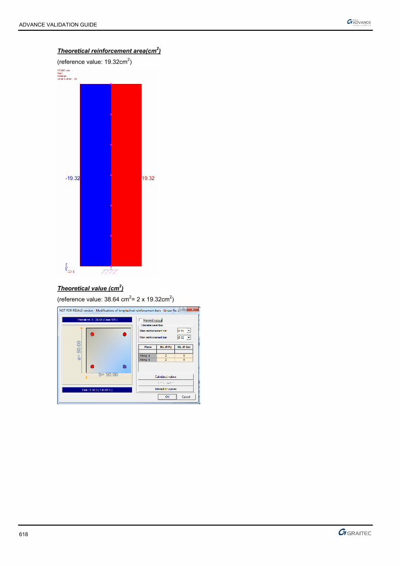
ADVANCE VALIDATION GUIDE
618
Theoretical reinforcement area(cm2)
(reference value: 19.32cm2)
Theoretical value (cm2)
(reference value: 38.64 cm2= 2 x 19.32cm2)
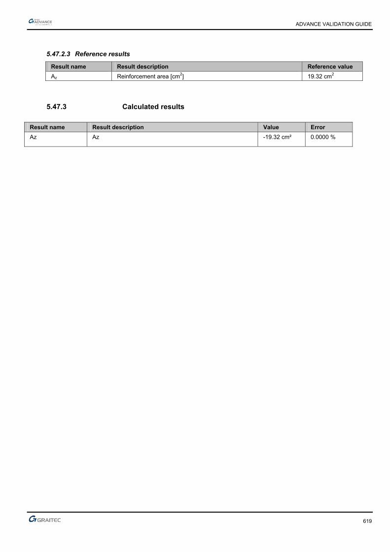
ADVANCE VALIDATION GUIDE
619
5.47.2.3 Reference results
Result name Result description Reference value
Az Reinforcement area [cm2] 19.32 cm2
5.47.3 Calculated results
Result name Result description Value Error
Az Az -19.32 cm² 0.0000 %
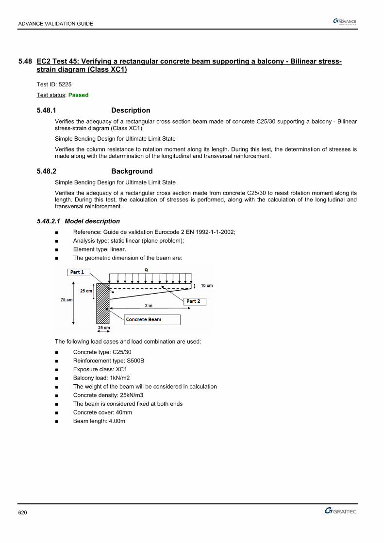
ADVANCE VALIDATION GUIDE
620
5.48 EC2 Test 45: Verifying a rectangular concrete beam supporting a balcony - Bilinear stress-strain diagram (Class XC1)
Test ID: 5225
Test status: Passed
5.48.1 Description
Verifies the adequacy of a rectangular cross section beam made of concrete C25/30 supporting a balcony - Bilinear stress-strain diagram (Class XC1).
Simple Bending Design for Ultimate Limit State
Verifies the column resistance to rotation moment along its length. During this test, the determination of stresses is made along with the determination of the longitudinal and transversal reinforcement.
5.48.2 Background
Simple Bending Design for Ultimate Limit State
Verifies the adequacy of a rectangular cross section made from concrete C25/30 to resist rotation moment along its length. During this test, the calculation of stresses is performed, along with the calculation of the longitudinal and transversal reinforcement.
5.48.2.1 Model description
■ Reference: Guide de validation Eurocode 2 EN 1992-1-1-2002;
■ Analysis type: static linear (plane problem);
■ Element type: linear.
■ The geometric dimension of the beam are:
The following load cases and load combination are used:
■ Concrete type: C25/30
■ Reinforcement type: S500B
■ Exposure class: XC1
■ Balcony load: 1kN/m2
■ The weight of the beam will be considered in calculation
■ Concrete density: 25kN/m3
■ The beam is considered fixed at both ends
■ Concrete cover: 40mm
■ Beam length: 4.00m

ADVANCE VALIDATION GUIDE
621
Units
Metric System
Geometry
Beam cross section characteristics:
■ Height: h = 0.75 m,
■ Width: b = 0.25 m,
■ Length: L = 4.00 m,
■ Section area: A = 0.1875 m2 ,
■ Concrete cover: c=4cm
Boundary conditions
The boundary conditions are described below:
■ Outer:
► Support at start point (x=0) fixed connection,
► Support at end point (x = 4.00) fixed connection
■ Inner: None.
5.48.2.2 Reference results in calculating the concrete beam
The ULS load calculation:
The first step of the calculation is to determine charges transmitted to the beam:
■ Vertical loads applied to the beam (kN/ml) from the load distribution over the balcony
■ Rotation moment applied to the beam (kN/ml) from the load distribution over the balcony
Each action (self-weight and distributed load) is determined by summing the resulting vertical loads along the eaves and the torsional moment by multiplying the resultant by the corresponding lever arm.
CAUTION, different lever arm must be considered from the center of the beam (by adding therefore the half-width).
The results are displayed in the table below:

ADVANCE VALIDATION GUIDE
622
Load calculation:
From previously calculated results, the following stresses can be determined:
■ Shear: EdV
■ Bending moment: EdM
■ Torque: EdT
Shear and bending moment:
One can determine the load at ULS taken over by the beam:
mKNPu /14.212*5,144.13*35,1
For a beam fixed on both ends, the following values will be obtained:
Maximum shear (ULS):
MNKNlP
V uEd 042,03,42
2
4*14,21
2
*
Bending moment at the supports:
MNmKNmlP
M uEd 028,02,28
12
²4*14,21
12
²*
Maximum Moment at middle of span:
MNmKNmlP
M uEd 014,01,14
24
²4*14,21
24
²*
Torsion moment:
For a beam subjected to a torque constant:
mMNmmKNmmtu /015,0/97,1425,2*5,159,8*35,1
MNml
mT tuEd 03,02
4*015,0
2*

ADVANCE VALIDATION GUIDE
623
5.48.2.3 Bending rebar
Span reinforcement (at bottom fiber)
007,067.16*²70.0*25,0
014,0cu
0088,0007,0*211*25,1 u
mzc 697,00088,0*4,01*70.0
²46.0²10*62.478,434*697,0
014,0 4 cmmAu
Minimum reinforcement percentage verification:
db
dbf
f
MaxA
w
wyk
effct
s
**0013.0
***26.0 ,
min,
Cracking matrix required (calculation hypothesis): Mpaff ctmeffct 56.2,
²27.2
²27.270.0*25.0*0013.0**0013.0
²27.270.0*25.0*500
56.2*26.0***26.0 ,
min, cm
cmdb
cmdbf
f
MaxA
w
wyk
effct
s
Therefore, it retains 2.27 cm ².
Reinforcement on supports (at top fiber)
014,067.16*²70.0*25,0
028,0cu
018,0014,0*211*25,1 u
mzc 695,0018,0*4,01*70.0
²93.0²10*27.978,434*695,0
028,0 4 cmmAu
It also retains 2.27 cm ² (minimum percentage).
Shear reinforcement
MNVEd 042,0
The transmission to the support is not direct; it is considered a connecting rod inclined by 45˚, therefore 1cot
Concrete rod verification:
²cot1
cotcot****max,
cdwRd fvzbV
According to: EC2 Part 1,1 EN 1992-1-1-2004 Chapter 6.2.3(4)
mzz c 695.0 (from the design in simple bending of support)
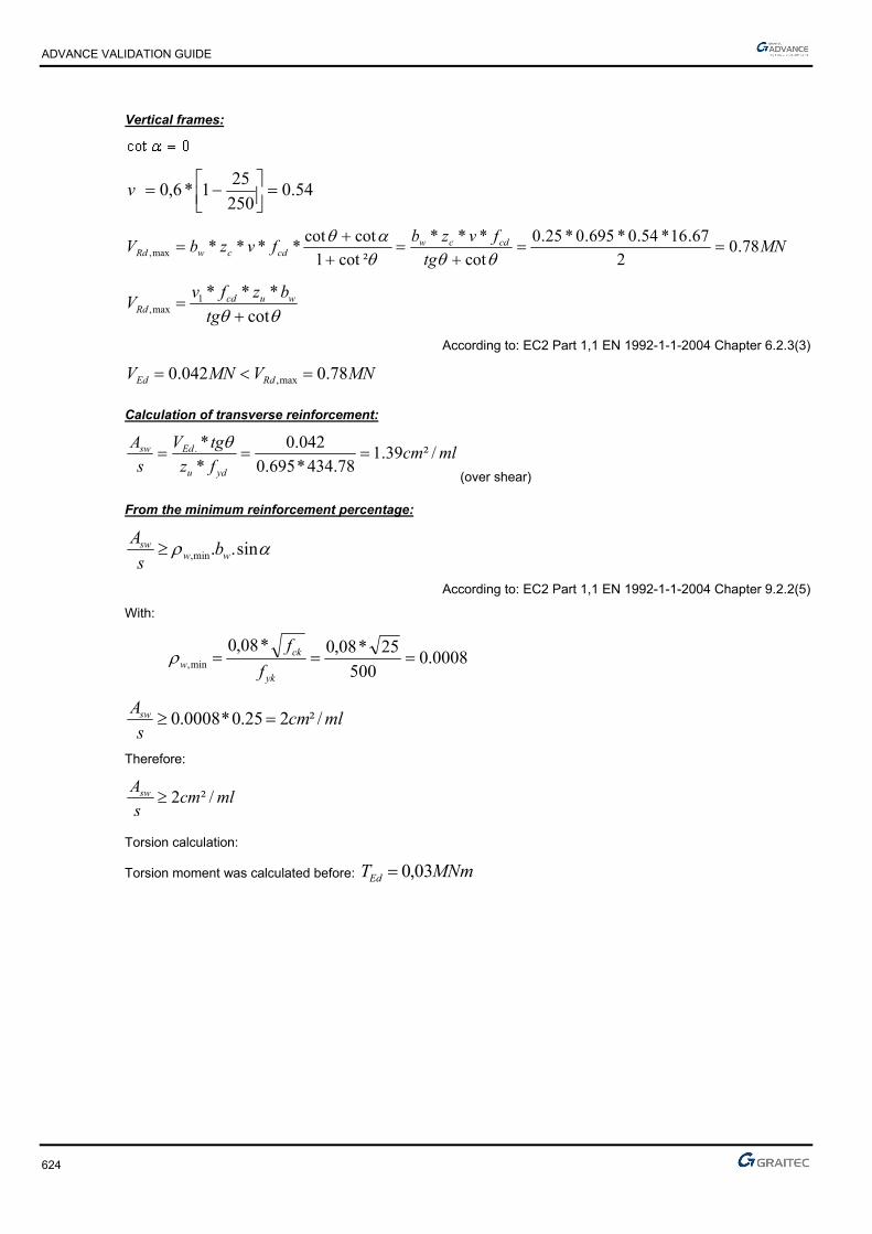
ADVANCE VALIDATION GUIDE
624
Vertical frames:
54.0250
251*6,0
v
MNtg
fvzbfvzbV cdcwcdcwRd 78.0
2
67.16*54.0*695.0*25.0
cot
***
²cot1
cotcot****max,
cot
***1max,
tg
bzfvV wucdRd
According to: EC2 Part 1,1 EN 1992-1-1-2004 Chapter 6.2.3(3)
MNVMNV RdEd 78.0042.0 max,
Calculation of transverse reinforcement:
mlcmfz
tgV
s
A
ydu
Edsw /²39.178.434*695.0
042.0
*
*.
(over shear)
From the minimum reinforcement percentage:
sin..min, wwsw bs
A
According to: EC2 Part 1,1 EN 1992-1-1-2004 Chapter 9.2.2(5)
With:
0008.0500
25*08,0*08,0min,
yk
ckw f
f
mlcms
Asw /²225.0*0008.0
Therefore:
mlcms
Asw /²2
Torsion calculation:
Torsion moment was calculated before: MNmTEd 03,0

ADVANCE VALIDATION GUIDE
625
Torsional shear stress:
kief
Edit At
T
**2 ,,
According to: EC2 Part 1,1 EN 1992-1-1-2004 Chapter 6.3.2(1)
cmcmu
Acmc
t ief 375.9375.9)7525(2
)75*25(8*2
max,
²1025.0²1025)375.975(*)375.925( mcmAk
Mpa..*.*
.
A*t*
T
ki,ef
Edi,t 561
102500937502
030
2τ
Concrete verification:
Calculate the maximum allowable stress in the rods:
cos*sin******2 ,max, iefkcdcwRd tAfvT
According to: EC2 Part 1,1 EN 1992-1-1-2004 Chapter 6.3.2(4)
54.0250
1*6,0
ckfv
MNTRd 085.070.0*70.0*09375.0*1025.0*67.16*54.0*2max,
Because of the combined share/moment effect, we must calculate:
0,1max,max,
Rd
Ed
Rd
Ed
V
V
T
T
According to: EC2 Part 1,1 EN 1992-1-1-2004 Chapter 6.3.2(4)
0,1399.078.0
042.0
085.0
03.0
Torsion longitudinal reinforcement
cot***2
*
ydk
kEdl fA
uTA
According to: EC2 Part 1,1 EN 1992-1-1-2004 Chapter 6.3.2(3)
mcmthtbu efefk 625.15.162)]375.975()375.925[(*2)]()[(*2
²47.578.434*1025.0*2
625.1*03.0cmAl
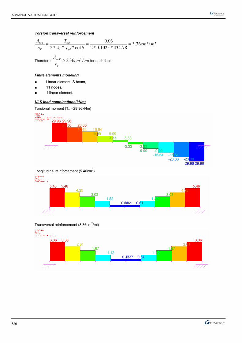
ADVANCE VALIDATION GUIDE
626
Torsion transversal reinforcement
mlcmfA
T
s
A
ydk
Ed
T
swT /²36.378.434*1025.0*2
03.0
cot***2
Therefore mlcms
A
T
swT /²36,3 for each face.
Finite elements modeling
■ Linear element: S beam,
■ 11 nodes,
■ 1 linear element.
ULS load combinations(kNm)
Torsional moment (Ted=29.96kNm)
Longitudinal reinforcement (5.46cm2)
Transversal reinforcement (3.36cm2/ml)

ADVANCE VALIDATION GUIDE
627
5.48.2.4 Reference results
Result name Result description Reference value
Mx Torsional moment [kNm] 29.96 cm2
Al Longitudinal reinforcement [cm2] 5.46 cm2
Ator,y Transversal reinforcement [cm2/ml] 3.36 cm2/ml
5.48.3 Calculated results
Result name Result description Value Error
Mx Mx 29.9565 kN*m 0.0000 %
Al Al 5.4595 cm² 0.0000 %
Ator,y / face Ator,y/face 3.35969 cm² 0.0001 %

ADVANCE VALIDATION GUIDE
628
5.49 EC2 Test 46 II: Verifying a square concrete beam subjected to a normal force of traction - Bilinear stress-strain diagram (Class X0)
Test ID: 5231
Test status: Passed
5.49.1 Description
Verifies a square cross section beam made of concrete C20/25 subjected to a normal force of traction - Bilinear stress-strain diagram (Class X0).
Tie sizing
Bilinear stress-strain diagram
Determines the armature of a pulling reinforced concrete, subjected to a normal force of traction.
The load combinations will produce the following rotation efforts:
NEd=1.35*233.3+1.5+56.67=400kNm
The boundary conditions are described below:
- Support at start point (x=0) fixed connection
- Support at end point (x = 5.00) translation along the Z axis is blocked
5.49.2 Background
Tie sizing
Bilinear stress-strain diagram / Inclined stress-strain diagram
Determine the armature of a pulling reinforced concrete, C20/25, subjected to a normal force of traction.
5.49.2.1 Model description
■ Reference: Guide de validation Eurocode 2 EN 1992-1-1-2002;
■ Analysis type: static linear (plane problem);
■ Element type: linear.
The following load cases and load combination are used:
■ Loadings from the structure: Fx,G = 233.33 kN
The dead load is neglected
■ Exploitation loadings (category A): Fx,Q = 56.67kN
■ The ultimate limit state (ULS) combination is: Cmax = 1.35 x G + 1.5 x Q
Units
Metric System

ADVANCE VALIDATION GUIDE
629
Geometry
Below are described the beam cross section characteristics:
■ Height: h = 0.15 m,
■ Width: b = 0.15 m,
■ Length: L = 5.00 m,
■ Section area: A = 0.00225 m2 ,
■ Concrete cover: c=3cm
■ Reinforcement S400, Class: B
■ Fck=20MPa
■ The load combinations will produce the following rotation efforts:
NEd=1.35*233.3+1.5+56.67=400kNm
Boundary conditions
The boundary conditions are described below:
■ Outer:
► Support at start point (x = 0) fixed connection,
► Support at end point (x = 5.00) translation along the Z axis is blocked
■ Inner: None.
5.49.2.2 Reference results in calculating the concrete beam
There will be two successive calculations, considering a bilinear stress-strain diagram constitutive law and then a inclined stress-strain diagram constitutive law.
Calculations according a bilinear stress-strain diagram
²50,11²10*50,11
15.1
400400.0 4
,, cmm
NA
Us
EdUs
It will be used a 4HA20=A=12.57cm2
Calculations according a inclined stress-strain diagram
MPaClassBS Us 373400 ,
²70,10²10*72,10373
400.0 4
,, cmm
NA
Us
EdUs
It can be seen that the gain is not negligible (about 7%).
Checking the condition of non-fragility:
yk
ctmcs f
fAA *
MPaff ckctm 21,220*30.0*30.0 3/23/2
²0225.015.0*15.0 mAc
²24.1400
21.2*0225.0* cm
f
fAA
yk
ctmcs
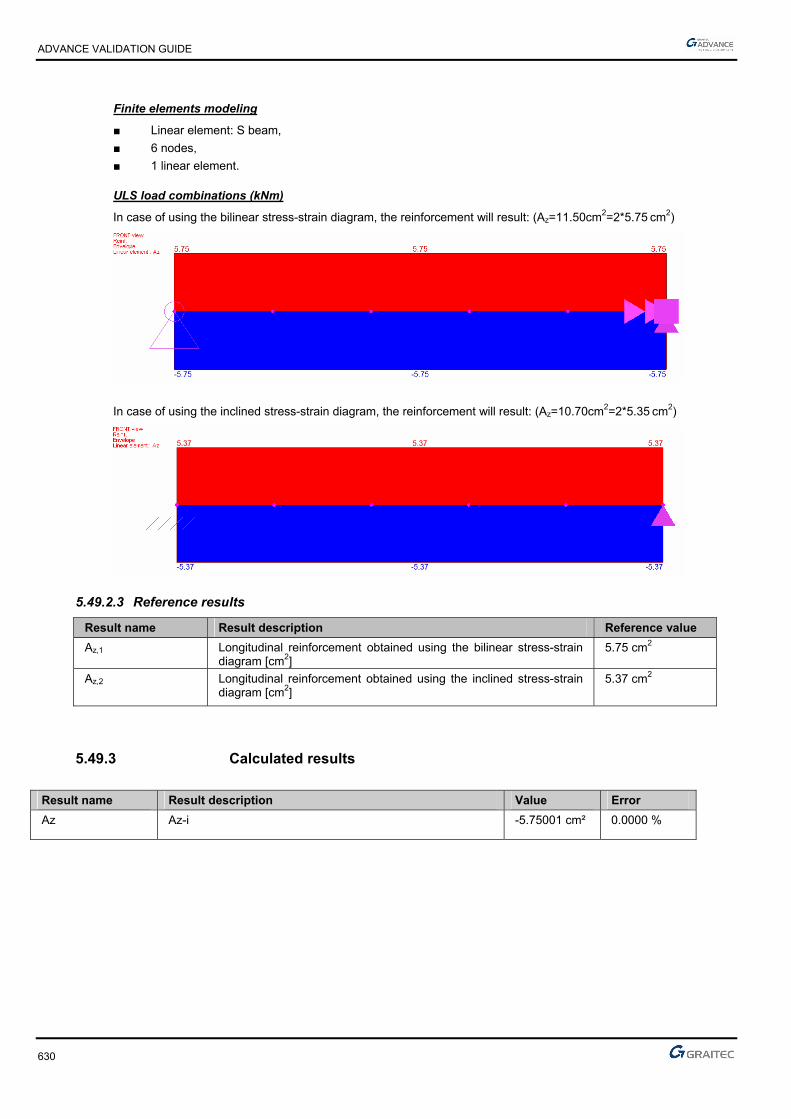
ADVANCE VALIDATION GUIDE
630
Finite elements modeling
■ Linear element: S beam,
■ 6 nodes,
■ 1 linear element.
ULS load combinations (kNm)
In case of using the bilinear stress-strain diagram, the reinforcement will result: (Az=11.50cm2=2*5.75 cm2)
In case of using the inclined stress-strain diagram, the reinforcement will result: (Az=10.70cm2=2*5.35 cm2)
5.49.2.3 Reference results
Result name Result description Reference value
Az,1 Longitudinal reinforcement obtained using the bilinear stress-strain diagram [cm2]
5.75 cm2
Az,2 Longitudinal reinforcement obtained using the inclined stress-strain diagram [cm2]
5.37 cm2
5.49.3 Calculated results
Result name Result description Value Error
Az Az-i -5.75001 cm² 0.0000 %

ADVANCE VALIDATION GUIDE
631
5.50 EC2 Test 44: Verifying a rectangular concrete beam subjected to eccentric loading - Bilinear stress-strain diagram (Class X0)
Test ID: 5213
Test status: Passed
5.50.1 Description
Verifies a rectangular cross section beam made of concrete C30/37 subjected to eccentric loading - Bilinear stress-strain diagram (Class X0).
The verification of the bending stresses at ultimate limit state is performed.
Simple Bending Design for Ultimate Limit State
During this test, the determination of stresses is made along with the determination of the longitudinal and transversal reinforcement.
- Support at start point (x = 0) fixed connection
- Support at end point (x = 5.00) fixed connection
5.50.2 Background
Simple Bending Design for Ultimate Limit State
Verifies the adequacy of a rectangular cross section made from concrete C30/37 to resist eccentric loading. During this test, the calculation of stresses is made along with the calculation of the longitudinal and transversal reinforcement.
5.50.2.1 Model description
■ Reference: Guide de validation Eurocode 2 EN 1992-1-1-2002;
■ Analysis type: static linear (plane problem);
■ Element type: linear.
The following load cases and load combination are used:
■ Loadings from the structure: G = 12 kN/m
The dead load is neglected
■ Exploitation loadings (category A): Q = 3kN/m,
■ The ultimate limit state (ULS) combination is: Cmax = 1.35 x G + 1.5 x Q
Units
Metric System
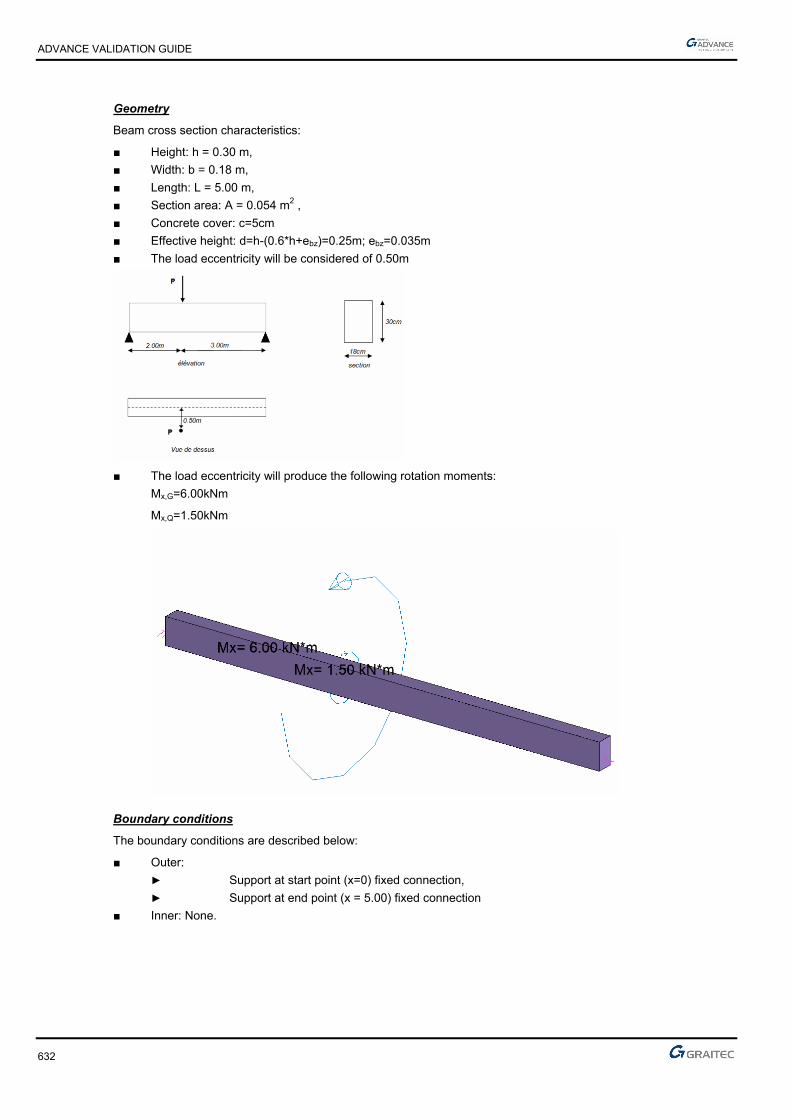
ADVANCE VALIDATION GUIDE
632
Geometry
Beam cross section characteristics:
■ Height: h = 0.30 m,
■ Width: b = 0.18 m,
■ Length: L = 5.00 m,
■ Section area: A = 0.054 m2 ,
■ Concrete cover: c=5cm
■ Effective height: d=h-(0.6*h+ebz)=0.25m; ebz=0.035m
■ The load eccentricity will be considered of 0.50m
■ The load eccentricity will produce the following rotation moments:
Mx,G=6.00kNm
Mx,Q=1.50kNm
Boundary conditions
The boundary conditions are described below:
■ Outer:
► Support at start point (x=0) fixed connection,
► Support at end point (x = 5.00) fixed connection
■ Inner: None.

ADVANCE VALIDATION GUIDE
633
Reference results in calculating the concrete beam
The moment is defined by the following formulas:
PPba
bePTA 10
3
5
3**5,0**
PPba
aePTB 5
1
5
2**5,0**
Note: the diagram of bending moment is the same as the shear force multiplied by the eccentricity.
The ULS load calculation:
kNPu 70.203*5.112*35.1
Before the point of application of torque, the torque is:
KNmPT uEd 21.67,20*10
3*
10
3
After the point of application of torque, the torque is:
KNmP
T uEd 14.4
5
7.20
5
Result ADVANCE Design 2012 - Moment: (in kNm)
Reference value: 6.21 kNm and -4.14kNm

ADVANCE VALIDATION GUIDE
634
5.50.2.2 Calculation in pure bending
Bending moment at ULS:
KNPu 7,203*5,112*35,1
MNmKNmP
M uEd 0248,084,24
5
7,20*6
5
*6
Simple bending design:
110,020*²25.0*18,0
0248,0cu
146,0110,0*211*25,1 u
mzc 235,0146,0*4,01*25.0
²43,2²10*43,278,434*235,0
0248,0 4 cmmAu
5.50.2.3 Torsion reinforcement
Torsion longitudinal reinforcement - Before application of the moment
cot***2
*
ydk
kEdl fA
uTA
According to: EC2 Part 1,1 EN 1992-1-1-2004 Chapter 6.3.2(3)
))()((*2 efefk thtbu
)(*)( efefk thtbA
with:
mu
Actef 07.005625.0;07.0max
3.018.0*2
30.0*18.0;035.0*2max;*2max
mcmuk 68.068))730()718((*2
²0253.0²253)730(*)718( mcmAk
²92.178.434*0253.0*2
68.0*0062.0cmAl
Torsion longitudinal reinforcement - After application of the moment
²28.178.434*0253.0*2
68.0*00414.0cmAl
Torsion transversal reinforcement - Before application of the moment
mlcmfA
T
s
A
ydk
Ed
T
swT /²82.278.434*0253.0*2
0062.0
cot***2

ADVANCE VALIDATION GUIDE
635
Torsion transversal reinforcement - After application of the moment
mlcmfA
T
s
A
ydk
Ed
T
swT /²88.178.434*0253.0*2
00414.0
cot***2
Concrete verification:
Calculation of the maximum allowable stress under torsional moment:
cos*sin******2 ,max, iefkcdcwRd tAfvT
According to: EC2 Part 1,1 EN 1992-1-1-2004 Chapter 6.3.2(4)
528.0250
1*6,0
ckfv
MNTRd 018.070.0*70.0*07.0*0253.0*20*528.0*2max,
Calculation of the maximum allowable stress under shear:
²cot1
cotcot****max,
cdwRd fvzbV
According to: EC2 Part 1,1 EN 1992-1-1-2004 Chapter 6.2.3(3)
mzz c 235.0 (from the design in simple bending)
Vertical reinforcement: 1cot
528.0250
301*6,0
v
MNfvzbV cdcwRd 223.02
1*20*528.0*235.0*18.0
²cot1
cotcot****max,
Because of the combined shear/moment effect, it must be calculated:
0,1max,max,
Rd
Ed
Rd
Ed
V
V
T
T
According to: EC2 Part 1,1 EN 1992-1-1-2004 Chapter 6.3.2(4)
0,1400.0223.0
0124.0
018.0
0062.0
Finite elements modeling
■ Linear element: S beam,
■ 6 nodes,
■ 1 linear element.

ADVANCE VALIDATION GUIDE
636
ULS load combinations(kNm)
Longitudinal reinforcement (Al=1.92cm2 and Al=1.28cm2)
Transversal reinforcement (2.82cm2/ml and 1.88cm2/ml)
5.50.2.4 Reference results
Result name Result description Reference value
Al,1 Longitudinal reinforcement for the first part [cm2] 1.92 cm2
Al,2 Longitudinal reinforcement for the second part [cm2] 1.28 cm2
Ator,y,1 Transversal reinforcement for the first part [cm2/ml] 2.82 cm2/ml
Ator,y,2 Transversal reinforcement for the second part [cm2/ml] 1.88 cm2/ml
5.50.3 Calculated results
Result name Result description Value Error
Al Al,1 1.91945 cm² 0.0002 %
Al Al,2 1.27964 cm² -0.0003 %
Ator,y / face Ator,y,1 2.82273 cm² -0.0001 %
Ator,y / face Ator,y,2 1.88182 cm² -0.0001 %

ADVANCE VALIDATION GUIDE
637
5.51 EC2 Test35: Verifying a rectangular concrete column subjected to compression to top – Based on nominal rigidity method - Bilinear stress-strain diagram (Class XC1)
Test ID: 5123
Test status: Passed
5.51.1 Description
Verifies the adequacy of a rectangular concrete column made of concrete C30/37 subjected to compression to top – Based on nominal rigidity method- Bilinear stress-strain diagram (Class XC1).
Based on nominal rigidity method
The purpose of this test is to determine the second order effects by applying the nominal rigidity method, and then calculate the frames by considering a section symmetrically reinforced.
The column is considered connected to the ground by a fixed connection and free to the top part.
5.51.2 Background
Based on nominal rigidity method
Verify the adequacy of a rectangular cross section made from concrete C30/37.
The purpose of this test is to determine the second order effects by applying the nominal rigidity method, and then calculate the frames by considering a section symmetrically reinforced.
5.51.2.1 Model description
■ Reference: Guide de validation Eurocode 2 EN 1992-1-1-2002;
■ Analysis type: static linear (plane problem);
■ Element type: linear.
The following load cases and load combination are used:
■ Loadings from the structure:
► 0.45 MN axial force
► 0.10 MNm rotation moment applied to the column top
► The self-weight is neglected
■ Exploitation loadings:
► 0.50 MN axial force
► 0.06 MNm rotation moment applied to the column top
■ 3,02
■ The ultimate limit state (ULS) combination is: Cmax = 1.35 x G + 1.5 x Q
■ Characteristic combination of actions: CCQ = 1.0 x G + 0.3 x Q
■ Concrete cover 5cm
■ Concrete C30/37
■ Steel reinforcement S500B
■ The column is considered isolated and braced

ADVANCE VALIDATION GUIDE
638
Units
Metric System
Geometry
Below are described the beam cross section characteristics:
■ Height: h = 0.45 m,
■ Width: b = 0.60 m,
■ Length: L = 4.50 m,
■ Concrete cover: c = 5cm along the long section edge and 3cm along the short section edge
Boundary conditions
The boundary conditions are described below:
The column is considered connected to the ground by a fixed connection and free to the top part.
Loading
The beam is subjected to the following load combinations:
■ Load combinations:
The ultimate limit state (ULS) combination is:
NEd =1.35*0.45+1.5*0.50=1.3575MN
MED=1.35*0.10+0.30*0.06=0.225MNm
■ me 166.03575.1
225.00

ADVANCE VALIDATION GUIDE
639
5.51.2.2 Reference results in calculating the concrete column
Geometric characteristics of the column:
The column has a fixed connection on the bottom end and is free on the top end, therefore, the buckling length is considered to be:
mll 950.4*2*20
According to Eurocode 2 – EN 1992-1-1 -2004; Chapter 5.8.3.2(1); Figure 5.7 b)
Calculating the slenderness of the column:
28.6945.0
9*32*32 0 a
l
Effective creep coefficient calculation:
The creep coefficient is calculated using the next formula:
Ed
EQPef M
Mt ., 0
According to Eurocode 2 – EN 1992-1-1 -2004; Chapter 5.8.4(2)
Where:
0,t creep coefficient
EQPM serviceability firs order moment under quasi-permanent load combination
EdM ULS first order moment (including the geometric imperfections)
MNmM Eqp 118.006.0*3.010.00
MNmM Ed 225.00
The moment report becomes:
524.0225.0
118.0
0
0 Ed
Eqp
M
M
The creep coefficient 0,t
is defined as follows:
)(*)(*),( 00 tft cmRH
MPaf
fcm
cm 73.2830
8.168.16)(
488.0281.0
1
1.0
1)(
20.020.00
0
t
t (for t0= 28 days concrete age).
213
0
***1.0100
11
h
RH
RH
RH =relative humidity; RH=50%

ADVANCE VALIDATION GUIDE
640
Where 121 if MPafcm 35 if not
7.0
1
35
cmf and
2.0
2
35
cmf
mmu
Ach 274
700450*2
700*450*2*20
MPaMPafcm 3538 ,
Therefore:
944.038
35357.07.0
1
cmf and 984.0
38
35352.02.0
2
cmf
70.1984.0*944.0*274*1.0
100
501
1***1.0100
11
3213
0
h
RH
RH
26.2488.0*73.2*70.1)(*)(*),( 00 tft cmRH
The effective creep coefficient calculation:
18.1524.0*26.2*, 0 Ed
EQPef M
Mt
According to Eurocode 2 – EN 1992-1-1 -2004; Chapter 5.8.4(2)
18.218.111 ef
The necessity of buckling calculation (second order effect):
For an isolated column, the slenderness limit check is done using the next formula:
n
CBA ***20lim
According to Eurocode 2 – EN 1992-1-1 -2004; Chapter 5.8.3.1(1)
Where:
215.020*70.0*45.0
3575.1
*
cdc
Ed
fA
Nn
81.018.1*2.01
1
*2,01
1
ef
A
because the reinforcement ratio in not yet known
because the ratio of the first order moment is not known
90.26215.0
7.0*1.1*85.0*20lim
90.2628.69 lim
Therefore, the second order effects most be considered

ADVANCE VALIDATION GUIDE
641
5.51.2.3 The eccentricity calculation and the corrected loads on ULS:
Initial eccentricity:
me 166.03575.1
225.00
Additional eccentricity:
First order eccentricity- stresses correction:
MNNEd 3575.1
cmmeee i 85.181885.001
MNmMEd 256.0
Reinforcement calculation in the first order situation:
To play the nominal rigidity method a starting section frame is needed. For this it will be used a concrete section considering only the first order effects.
Advance Design iterates as many time as necessary.
The needed frames will be determined assuming a compound bending with compressive stress. All the results above were obtained in the center of gravity for the concrete section alone. The stresses must be reduced in the centroid of the tensioned steel.
MNmh
dNMM Gua 494.02
45.040.0*3575.1256.0)
2(*0
Verification if the section is partially compressed:
495,0)40,0
45,0*4,01(*
40,0
45,0*8,0)*4,01(**8,0
d
h
d
hBC
220.020*²40.0*70.0
495.0
*²*
cdw
uacu fdb
M
BCcu 495.0220.0 therefore the section is partially compressed.

ADVANCE VALIDATION GUIDE
642
Calculations of steel reinforcement in pure bending:
220.0cu
315,0)220,0*21(1*25,1 u
mdz uc 350,0)315,0*4,01(*40,0)*4,01(*
²46.3278,434*350,0
495,0
*cm
fz
MA
ydc
ua
Calculations of steel reinforcement in combined bending:
For the combined bending:
24 24.178.434
3575.110*46.32' cm
f
NAA
yd
The minimum reinforcement percentage:
2min, 3.6*002.0²12.3
78.434
3575.1*10.0*10,0cmAcm
f
NA c
yd
Eds
The reinforcement will be 8HA10 representing a 6.28cm2 section
The second order effects calculation:
The second order effect will be determined by applying the method of nominal rigidity:
Calculation of nominal rigidity:
It is estimated nominal rigidity of a post or frame member from the following formula:
sssccdc IEKIEKEI ****
With:
2.1cm
cd
EE
MPaMPaff ckcm 388
MPaf
E cmcm 32837
10
38*22000
10*22000
3.03.0
MPaE
E cmcd 27364
2.1
32837
2.1
410*316.512
45.0*70.0
12
* 333
mhb
Ic (concrete only inertia)
MPaEs 200000
sI : Inertia
002.040.0*70.0
10*28,6 4
c
s
A
A

ADVANCE VALIDATION GUIDE
643
01.0002.0 c
s
A
A
Mpaf
k ck 22.120
30
201
215.020*70.0*45.0
3575.1
.
cdc
Ed
fA
Nn
20.0088.0170
28.69*215.0
170*2
nk
45242
10.92,105.02
45.0*
2
10.28,6*2
2*
2*2 mc
hAI ss
1sK and 049.018.11
088.0*22.1
1
* 21
ef
c
kkK
Therefore:
²97.1010*92.1*200000*110*316.5*27364*049.0 53 MNmEI
Stresses correction:
The total moment, including second order effects, is defined as a value plus the time of the first order:
11*0
Ed
BEdEd
N
NMM
MNmM Ed 0256.00 (moment of first order (ULS) taking into account geometric imperfections
MNNEd 3575.1 (normal force acting at ULS).
0
²
c
and 80 c the moment is constant (no horizontal force at the top of post).
234.18
²
MNl
EINB 32.1
²9
82.10*²*² 2
0
The second order moment is:
MNmMEd 18.111
3575.1
32.1234.1
1*256.02
An additional iteration must be made by increasing the ratio of reinforcement.
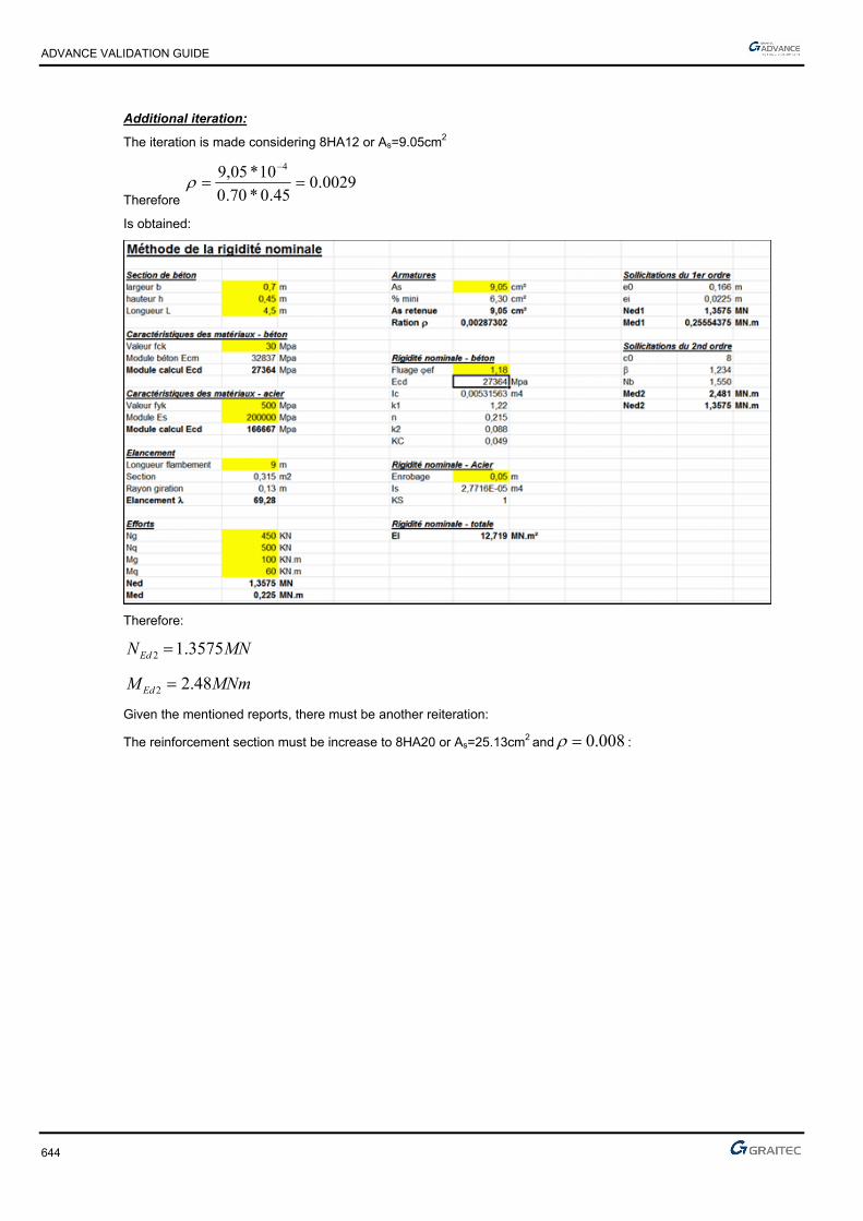
ADVANCE VALIDATION GUIDE
644
Additional iteration:
The iteration is made considering 8HA12 or As=9.05cm2
Therefore 0029.0
45.0*70.0
10*05,9 4
Is obtained:
Therefore:
MNNEd 3575.12
MNmMEd 48.22
Given the mentioned reports, there must be another reiteration:
The reinforcement section must be increase to 8HA20 or As=25.13cm2 and 008.0 :
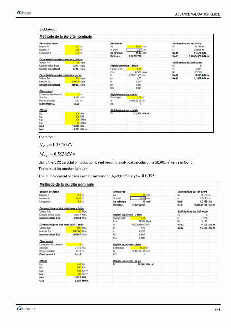
ADVANCE VALIDATION GUIDE
645
Is obtained:
Therefore:
MNNEd 3575.12
MNmMEd 563.02
Using the EC2 calculation tools, combined bending analytical calculation, a 28.80cm2 value is found.
There must be another iteration:
The reinforcement section must be increase to As=30cm2 and 0095.0 :

ADVANCE VALIDATION GUIDE
646
Therefore:
MNNEd 3575.12
MNmMEd 499.02
Using the EC2 calculation tools, combined bending analytical calculation, a 22.22cm2 value is found.
The theoretical reinforcement section of 30cm2 will be adopted.
Finite elements modeling
■ Linear element: S beam,
■ 6 nodes,
■ 1 linear element.
Theoretical reinforcement area(cm2)
(reference value: 16cm2 )
Theoretical value (cm2)
(reference value: 31.99cm2 = 2 x 15.99cm2)
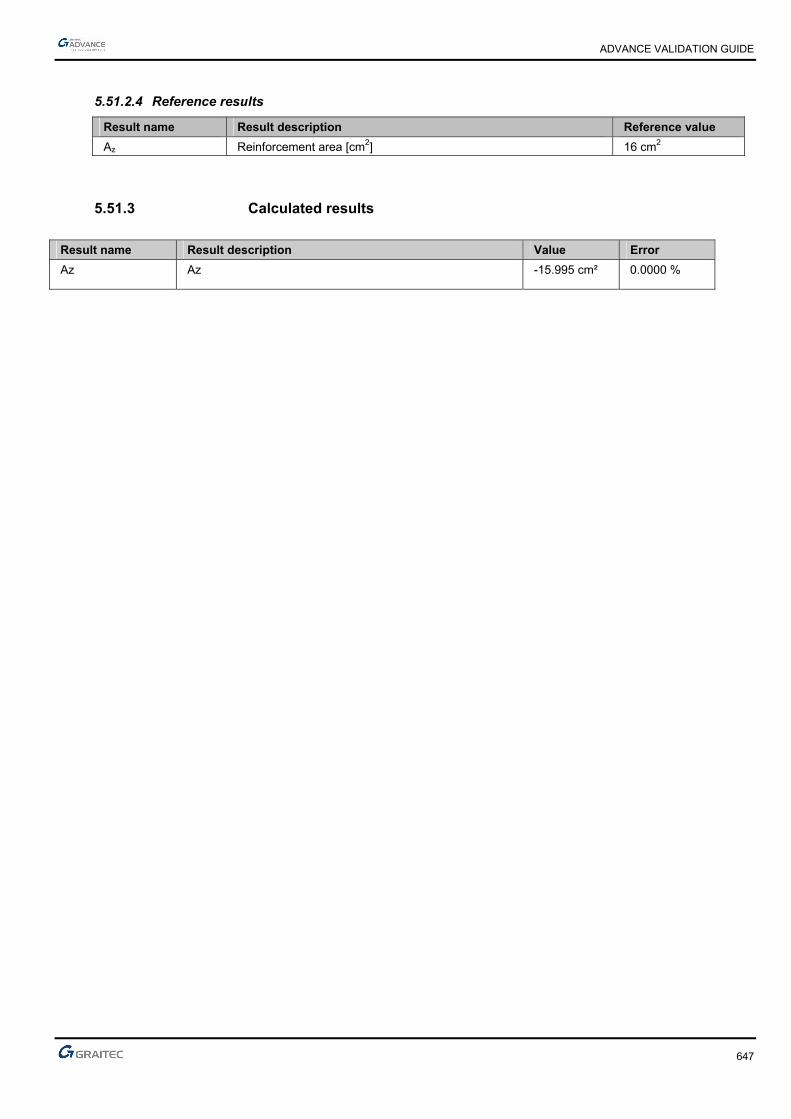
ADVANCE VALIDATION GUIDE
647
5.51.2.4 Reference results
Result name Result description Reference value
Az Reinforcement area [cm2] 16 cm2
5.51.3 Calculated results
Result name Result description Value Error
Az Az -15.995 cm² 0.0000 %
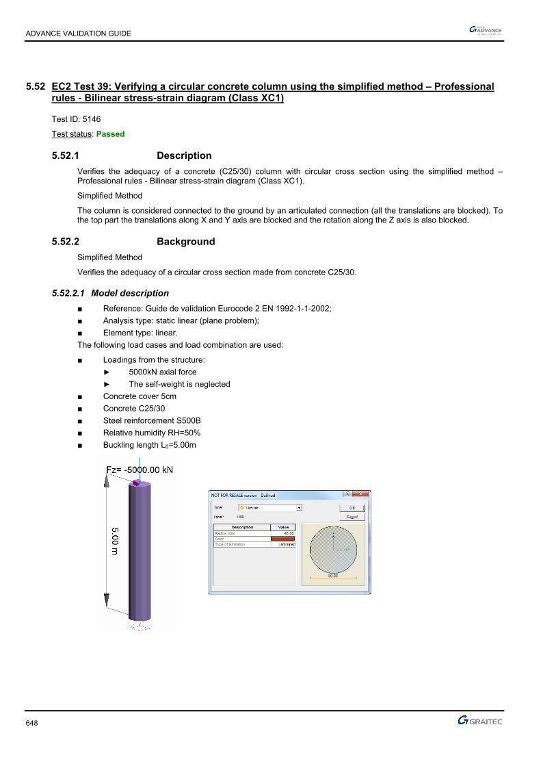
ADVANCE VALIDATION GUIDE
648
5.52 EC2 Test 39: Verifying a circular concrete column using the simplified method – Professional rules - Bilinear stress-strain diagram (Class XC1)
Test ID: 5146
Test status: Passed
5.52.1 Description
Verifies the adequacy of a concrete (C25/30) column with circular cross section using the simplified method – Professional rules - Bilinear stress-strain diagram (Class XC1).
Simplified Method
The column is considered connected to the ground by an articulated connection (all the translations are blocked). To the top part the translations along X and Y axis are blocked and the rotation along the Z axis is also blocked.
5.52.2 Background
Simplified Method
Verifies the adequacy of a circular cross section made from concrete C25/30.
5.52.2.1 Model description
■ Reference: Guide de validation Eurocode 2 EN 1992-1-1-2002;
■ Analysis type: static linear (plane problem);
■ Element type: linear.
The following load cases and load combination are used:
■ Loadings from the structure:
► 5000kN axial force
► The self-weight is neglected
■ Concrete cover 5cm
■ Concrete C25/30
■ Steel reinforcement S500B
■ Relative humidity RH=50%
■ Buckling length L0=5.00m

ADVANCE VALIDATION GUIDE
649
Units
Metric System
Geometry
Below are described the beam cross section characteristics:
■ Radius: r = 0.40 m,
■ Length: L = 5.00 m,
■ Concrete cover: c=5cm
Boundary conditions
The boundary conditions are described below:
The column is considered connected to the ground by a articulated connection (all the translations are blocked) and to the top part the translations along X and Y axis are blocked and the rotation along Z axis is also blocked.
Loading
The beam is subjected to the following load combinations:
■ Load combinations:
kNNED 67505000*35.1
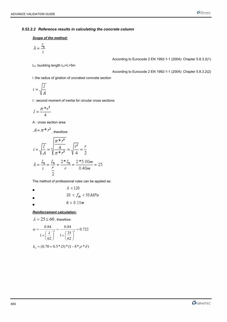
ADVANCE VALIDATION GUIDE
650
5.52.2.2 Reference results in calculating the concrete column
Scope of the method:
According to Eurocode 2 EN 1992-1-1 (2004): Chapter 5.8.3.2(1)
L0 :buckling length L0=L=5m
According to Eurocode 2 EN 1992-1-1 (2004): Chapter 5.8.3.2(2)
i :the radius of giration of uncraked concrete section
I : second moment of inertia for circular cross sections
A : cross section area
, therefore:
The method of professional rules can be applied as:
■
■
■
Reinforcement calculation:
6025 , therefore:
722.0
62
251
84.0
621
84.022
)**81(*)*5.070.0( Dkh
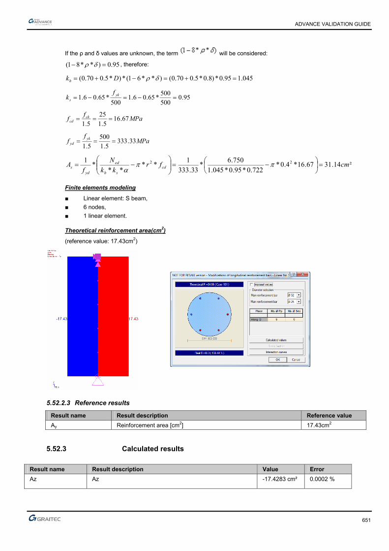
ADVANCE VALIDATION GUIDE
651
If the ρ and δ values are unknown, the term will be considered:
95.0)**81( , therefore:
045.195.0*)8.0*5.070.0()**61(*)*5.070.0( Dkh
95.0500
500*65.06.1
500*65.06.1 yk
s
fk
MPaf
f ckcd 67.16
5.1
25
5.1
MPaf
f ykyd 33.333
5.1
500
5.1
²14.3167.16*4.0*722.0*95.0*045.1
750.6*
33.333
1**
***
1 22 cmfrkk
N
fA cd
sh
ed
yds
Finite elements modeling
■ Linear element: S beam,
■ 6 nodes,
■ 1 linear element.
Theoretical reinforcement area(cm2)
(reference value: 17.43cm2)
5.52.2.3 Reference results
Result name Result description Reference value
Ay Reinforcement area [cm2] 17.43cm2
5.52.3 Calculated results
Result name Result description Value Error
Az Az -17.4283 cm² 0.0002 %

ADVANCE VALIDATION GUIDE
652
5.53 EC2 Test 43: Verifying a square concrete column subjected to a small rotation moment and significant compression force to the top with Nominal Curvature Method - Bilinear stress-strain diagram (Class XC1)
Test ID: 5211
Test status: Passed
5.53.1 Description
Verifies the adequacy of a square cross section column made of concrete C30/37 subjected to a small rotation moment and significant compression force to the top with Nominal Curvature Method - Bilinear stress-strain diagram (Class XC1).
The verification of the axial stresses and rotation moment, applied on top, at ultimate limit state is performed.
Nominal curvature method.
The purpose of this test is to determine the second order effects by applying the method of nominal rigidity, and then calculate the frames by considering a section symmetrically reinforced.
The column is considered connected to the ground by a fixed connection and free to the top part.
5.53.2 Background
Nominal curvature method.
Verify the adequacy of a rectangular cross section made from concrete C30/37.
The purpose of this test is to determine the second order effects by applying the method of nominal rigidity, and then calculate the frames by considering a section symmetrically reinforced.
5.53.2.1 Model description
■ Reference: Guide de validation Eurocode 2 EN 1992-1-1-2002;
■ Analysis type: static linear (plane problem);
■ Element type: linear.
The following load cases and load combination are used:
■ Loadings from the structure:
► 150 kN axial force
► 15 kMm rotation moment applied to the column top
► the self-weight is neglected
■ Exploitation loadings:
► 100 kN axial force
► 7 kNm rotation moment applied to the column top
■ ■ The ultimate limit state (ULS) combination is: Cmax = 1.35 x G + 1.5 x Q
■ Concrete cover 3cm and 5cm
■ Transversal reinforcement spacing a=40cm
■ Concrete C30/37
■ Steel reinforcement S500B
■ The column is considered isolated and braced

ADVANCE VALIDATION GUIDE
653
Units
Metric System
Geometry
Below are described the beam cross section characteristics:
■ Height: h = 0.50 m,
■ Width: b = 0.50 m,
■ Length: L = 5.80 m,
■ Concrete cover: c = 5 cm
Boundary conditions
The boundary conditions are described below:
The column is considered connected to the ground by a fixed connection and free to the top part.
Loading
The beam is subjected to the following load combinations:
■ Load combinations:
The ultimate limit state (ULS) combination is:
NEd =1.35*150+1.50*100=352.50kN=0.353MN
MEd=1.35*15+1.50*7=30.75kNm=0.03075MNm
■

ADVANCE VALIDATION GUIDE
654
5.53.2.2 Reference results in calculating the concrete column
Geometric characteristics of the column:
The column has a fixed connection on the bottom end and is free on the top end, therefore, the buckling length is considered to be:
mll 60.11*20
According to Eurocode 2 – EN 1992-1-1 -2004; Chapter 5.8.3.2(1); Figure 5.7 b)
Calculating the slenderness of the column:
37.8050.0
60.11*32*32 0 a
l
Effective creep coefficient calculation:
The creep coefficient is calculated using the next formula:
Ed
EQPef M
Mt ., 0
According to Eurocode 2 – EN 1992-1-1 -2004; Chapter 5.8.4(2)
Where:
0,t creep coefficient
EQPM serviceability firs order moment under quasi-permanent load combination
EdM ULS first order moment (including the geometric imperfections)
First order eccentricity evaluation:
ieee 01
mei 03.0
The first order moment provided by the quasi-permanent loads:
meN
Meee i
Eqp
Eqpi 125.030.0
100*30.0150
7*30.015
0
001
kNNEqp 180100*30.01501
MNmkNmeNM EqpEqp 0225.050.22125.0*180* 111
The first order ULS moment is defined latter in this example:
MNmMEd 041.01
The creep coefficient 0,t
is defined as follows:
)(*)(*),( 00 tft cmRH
72.2830
8.168.16)(
cm
cmf
f
488.0281.0
1
1.0
1)(
20.020.00
0
t
t (for t0= 28 days concrete age).
ADVANCE VALIDATION GUIDE
655
213
0
***1.0100
11
h
RH
RH
MPafcm 35 therefore: 944.038
35357.07.0
1
cmf and 984.0
38
35352.02.0
2
cmf
72.1984.0*944.0*250*1.0
100
501
1250500500*2
500*500*2*230
RHmm
u
Ach
28.2488.0*72.2*72.1)(*)(*),( 00 tft cmRH
The effective creep coefficient calculation:
25.1041.0
0225.0*28.2*, 0
Ed
EQPef M
Mt
The second order effects; The buckling calculation:
For an isolated column, the slenderness limit check is done using the next formula:
n
CBA ***20lim
According to Eurocode 2 – EN 1992-1-1 -2004; Chapter 5.8.3.1(1)
Where:
071.020*²50.0
353.0
*
cdc
Ed
fA
Nn
80.025.1*2.01
1
*2,01
1
ef
A
1.1*21 B because the reinforcement ratio in not yet known
70.07,1 mrC because the ratio of the first order moment is not known
24.46071.0
7.0*1.1*80.0*20lim
24.4637.80 lim
Therefore, the second order effects cannot be neglected.
Calculation of the eccentricities and solicitations corrected for ULS :
The stresses for the ULS load combination are:
NEd= 1.35*150 + 1.50*100= 352.5kN = 0,3525 MN
MEd= 1.35*15 + 1.50*7= 352.5kN= 0.03075MNm
Therefore it must be determined:
■ The eccentricity of the first order ULS moment, due to the stresses applied
■ The additional eccentricity considered for the geometrical imperfections

ADVANCE VALIDATION GUIDE
656
Initial eccentricity:
mN
Me
Ed
Ed 087.0353.0
03075.00
Additional eccentricity:
ml
ei 03.0400
6.11
4000
The first order eccentricity: stresses correction:
The forces correction, used for the combined flexural calculations:
MNNEd 353.0
meee i 117.001
MNmNeM EdEd 041.0353.0*117.0*1
0*eNM Ed
mmmm
mmmmmm
hmm
e 207.16
20max
30
50020
max30
20max0
According to Eurocode 2 – EN 1992-1-1 -2004; Chapter 6.1.(4)
Reinforcement calculation in the first order situation:
To apply the nominal rigidity method, we need an initial reinforcement area to start from. For this, the concrete section will be sized considering only the first order effect.
The Advance Design calculation is different: it is iterating as many time as necessary starting from the minimum percentage area.
The reinforcement is determined using a compound bending with compressive stress. The determined solicitations were calculated from the center of gravity of the concrete section alone. Those stresses must be reduced to the centroid of tensioned steel:
MNmh
dNMM Gua 112.02
50.045.0*353.0041.0)
2(*0

ADVANCE VALIDATION GUIDE
657
Verification about the partially compressed section:
494,0)45,0
50,0*4,01(*
45,0
50,0*8,0)*4,01(**8,0
d
h
d
hBC
055.020*²45.0*50.0
112.0
*²*
cdw
uacu fdb
M
494.0055.0 BCcu therefore the section is partially compressed
The calculation for the tensioned steel in pure bending:
055.0cu
071,0)055,0*21(1*25,1 u
mdz uc 437,0)071,0*4,01(*45,0)*4,01(*
²89,578,434*437,0
112,0
*cm
fz
MA
ydc
ua
The calculation for the compressed steel in bending:
For the compound bending:
The minimum column percentage reinforcement must be considered:
Therefore a 5cm2 reinforcement area will be considered
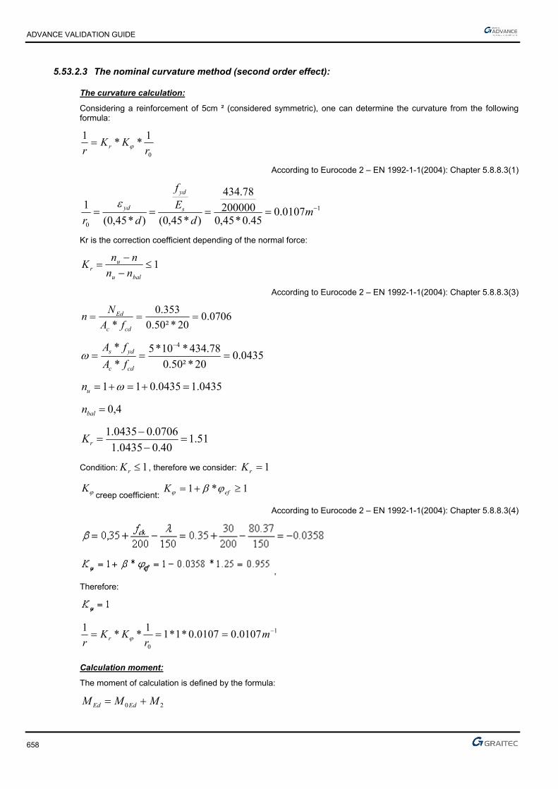
ADVANCE VALIDATION GUIDE
658
5.53.2.3 The nominal curvature method (second order effect):
The curvature calculation:
Considering a reinforcement of 5cm ² (considered symmetric), one can determine the curvature from the following formula:
0
1**
1
rKK
r r
According to Eurocode 2 – EN 1992-1-1(2004): Chapter 5.8.8.3(1)
1
0
0107.045.0*45,0
200000
78.434
)*45,0()*45,0(
1 md
E
f
drs
yd
yd
Kr is the correction coefficient depending of the normal force:
1
balu
ur nn
nnK
According to Eurocode 2 – EN 1992-1-1(2004): Chapter 5.8.8.3(3)
0706.020*²50.0
353.0
*
cdc
Ed
fA
Nn
0435.020*²50.0
78.434*10*5
*
* 4
cdc
yds
fA
fA
0435.10435.011 un
4,0baln
51.140.00435.1
0706.00435.1
rK
Condition: 1rK , therefore we consider: 1rK
K creep coefficient: 1*1 efK
According to Eurocode 2 – EN 1992-1-1(2004): Chapter 5.8.8.3(4)
,
Therefore:
1
0
0107.00107.0*1*11
**1 m
rKK
r r
Calculation moment:
The moment of calculation is defined by the formula:
20 MMM EdEd

ADVANCE VALIDATION GUIDE
659
Where:
EdM 0 is moment of the first order including geometric imperfections.
2M is nominal moment of second order.
The 2nd order moment is calculated from the curvature:
22 *eNM Ed
mc
l
re 144.0
10
²60.11*0107.0*
1 20
2
MNmeNM Ed 051.0144.0*353.0* 22
MNmMMM EdEd 09.0051.0041.020
The reinforcement must be sized considering the demands of the second degree effects, as follows:
Reinforcement calculation according the second order effects:
The interaction diagram will be used.
The input parameters in the diagram are:

ADVANCE VALIDATION GUIDE
660
According to the diagram, it will be obtained a minimal percentage reinforcement:
2min, 5*002.0²81.0
78.434
353.0*10.0*10,0cmAcm
f
NA c
yd
Eds
Finite elements modeling
■ Linear element: S beam,
■ 7 nodes,
■ 1 linear element.
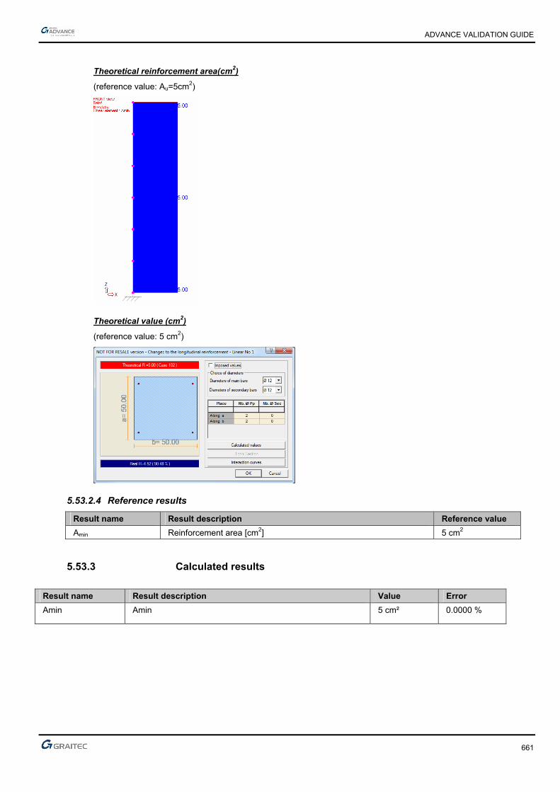
ADVANCE VALIDATION GUIDE
661
Theoretical reinforcement area(cm2)
(reference value: Au=5cm2)
Theoretical value (cm2)
(reference value: 5 cm2)
5.53.2.4 Reference results
Result name Result description Reference value
Amin Reinforcement area [cm2] 5 cm2
5.53.3 Calculated results
Result name Result description Value Error
Amin Amin 5 cm² 0.0000 %

ADVANCE VALIDATION GUIDE
662
5.54 Verifying the capacity design results according to Eurocode EC2 and EC8 French standards. (DEV2013 #8.3)
Test ID: 5602
Test status: Passed
5.54.1 Description
Verifies the capacity design results according to Eurocode EC2 and EC8 French standards.

ADVANCE VALIDATION GUIDE
663
5.55 EC2 Test 47: Verifying a rectangular concrete beam subjected to tension load - Bilinear stress-strain diagram (Class XD2)
Test ID: 5964
Test status: Passed
5.55.1 Description
Verifies a rectangular cross section beam made from concrete C25/30 to resist simple tension. Verification of the bending stresses at ultimate limit state and serviceability limit state is performed.
Verification is done according to EN 1992-1-1 French annex.
5.55.2 Background
Simple Bending Design for Ultimate and Service State Limit
Verifies the adequacy of a rectangular cross section made from concrete C25/30 to resist simple tension. During this test, the calculation of stresses is made along with the calculation of the longitudinal reinforcement and the verification of the minimum reinforcement percentage.
5.55.2.1 Model description
■ Reference: Guide de validation Eurocode 2 EN 1992-1-1-2002;
■ Analysis type: static linear (plane problem);
■ Element type: linear.
The following load cases and load combination are used:
■ Loadings from the structure: G = 135 kN/m (including dead load),
■ Exploitation loadings (category A): Q = 150kN/m,
■ ■ Characteristic combination of actions: CCQ = 1.0 x G + 1.0 x Q
■ Quasi-permanent combination of actions: CQP = 1.0 x G + 0.3 x Q
Units
Metric System
Geometry
Below are described the beam cross section characteristics:
■ Height: h = 0.20 m,
■ Width: b = 0.20 m,
■ Length: L = 5.00 m,
■ Section area: A = 0.04 m2 ,
■ Concrete cover: c=5.00cm

ADVANCE VALIDATION GUIDE
664
Materials properties
Rectangular solid concrete C25/30 and S500, class A reinforcement steel is used. The following characteristics are used in relation to this material:
■ Exposure class XD2
■ Concrete density: 25kN/m3
■ Stress-strain law for reinforcement: Bilinear stress-strain diagram
■ The concrete age t0=28 days
■ Humidity RH=50%
Boundary conditions
The boundary conditions are described below:
■ Outer:
► Support at start point (x=0) , fixed connection,
► Support at end point (x = 5.80) restrained in translation along Z.
■ Inner: None.
Loading
The beam is subjected to the following load combinations:
Load combinations:
■ Ultimate Limit State:
kN*.*.Q*.G*.NEd 4071505113535151351
■ Characteristic combination of actions:
KNQGN cq,ser 285150135
■ Quasi-permanent combination of actions:
KN*.Q*.GN qp,ser 1801503013530
ADVANCE VALIDATION GUIDE
665
5.55.2.2 Reference results in calculating the longitudinal reinforcement and the crack width
Calculating for ultimate limit state:
²37.9²10*37.9
15.1
500407.0 4
,, cmm
NA
Us
EdUs
Calculating for serviceability limit state:
S
sersers
NA
,
Mpaf yks 400500*8,0*8,0
²13.7²10*13.7400
285.0 4, cmmA sers
Final reinforcement
Is retained the steel section between the maximum theoretical calculation at ULS and calculating the SLS or
Ath = 9.37 cm ².
Therefore, 4HA20 = A = 12.57 cm ².
Constraint checking to the ELS:
MPaMPaA
Nss
sers
sers 40080.226
001257.0
285.0
,
Crack opening verification:
It will be checked the openings of cracks by considering 4HA20.
Calculating the maximum spacing between the cracks
The maximum spacing of cracks is given by the formula:
effpr
kkcks
,
213max,
***425.0*
According to: EC2 Part 1,1 EN 1992-1-1-2004 Chapter 7.3.4(3)
The effective depth “d” must be estimated by considering the real reinforcement of the beam:
cmd 4.132
26.0520
020.0100.0
2
20.0165.0)134.020.0(*5.2
min*20.0
2
)(*5.2min*,
hdh
bA effc
According to: EC2 Part 1,1 EN 1992-1-1-2004 Chapter 7.3.4(2); Figure: 7.1
²040.0, mA effc this value was multiplied by two because the section is fully stretched
031.0040.0
10*57.12 4
,,
effc
seffp A
A
According to: EC2 Part 1,1 EN 1992-1-1-2004 Chapter 7.3.4(2)

ADVANCE VALIDATION GUIDE
666
mmnn
nneq 20
**
**
2211
222
211
According to: EC2 Part 1,1 EN 1992-1-1-2004 Chapter 7.3.4(2)
effpr
kkcks
,
213max,
***425.0*
Concrete cover of 5cm and HA6 reinforcement, therefore c=5+0.6=5.6cm
801 .k HA bars
12 k pure tension sizing
99156
2543
2543
3232
3 .*.c
*.k//
mmkk
ckseffp
r 331031.0
20*1*8.0*425.056*99.1
***425.0*
,
213max,
Calculation of average deformations
35.631476
200000
cm
se E
E
According to: EC2 Part 1,1 EN 1992-1-1-2004 Chapter 7.3.4(2)
Steel stresses in SLSqp:
MpaA
N
sers
qpsers 2.143
001257.0
180.0
,
44 10304σ
6010175
200000
031035610310
56240143ρα1
ρσ
εε
*.E
*,*.
).*.(*.
.*.
E
)*(*f
*k
s
s
s
eff,peeff,p
eff,ctts
cmsm
According to: EC2 Part 1,1 EN 1992-1-1-2004 Chapter 7.3.4(2)
Calculation of crack widths:
mmsw cmsmrk 171.0)10*17.5(*331)(* 4max,
According to: EC2 Part 1,1 EN 1992-1-1-2004 Chapter 7.3.4(1)
For an exposure class XD2, applying the French national annex, it retained a maximum opening of 0.20mm crack.
This criterion is satisfied.

ADVANCE VALIDATION GUIDE
667
Checking the condition of non-fragility:
In case one control for cracking is required:
yk
ctmcs f
fAA .
Because h<0.3m
Mpaff ckctm 56,225*30.0*30.0 3/23/2
According to: EC2 Part 1,1 EN 1992-1-1-2002 Chapter 3.1.3(2);Table 3.1
²04.020.0*20.0 mAc
²05.2500
56.2*04.0* cm
f
fAA
yk
ctmcs
Finite elements modeling
■ Linear element: S beam,
■ 6 nodes,
■ 1 linear element.

ADVANCE VALIDATION GUIDE
668
Longitudinal reinforcement for ULS and SLS load combinations (kNm)
ULS (reference value: Az=9.36 cm2=2*4.68 cm2)
SLS (reference value: Az=7.12 cm2=2*3.56 cm2)
Stresses in the steel reinforcement
(reference value: s= 226.80Mpa)
Maximum spacing of cracks Sr, max (m)
(reference value: Sr,max= 0.331m)
Crack width wk (mm)
(reference value: wk= 0.171mm)

ADVANCE VALIDATION GUIDE
669
5.55.2.3 Reference results
Result name Result description Reference value
Az,ULS Theoretical reinforcement area for the ULS load combination [cm2] 4.68 cm2
s Stresses in steel reinforcement [MPa] 226.77 MPa
Sr, max Maximum spacing of cracks [m] 33.1 cm
wk Crack width [mm] 0.017 cm
5.55.3 Calculated results
Result name Result description Value Error
Az Az,USL -4.68337 cm² -0.0001 %
Ss CQ SigmaS -226.766 MPa 0.0016 %
Sr,max Sr,max 32.7639 cm -0.7155 %
wk wk -0.0170451 cm -0.2650 %

ADVANCE VALIDATION GUIDE
670
5.56 EC2 Test 4 II: Verifying a rectangular concrete beam subjected to Pivot B efforts – Inclined stress-strain diagram
Test ID: 5893
Test status: Passed
5.56.1 Description
Verifies the adequacy of a rectangular cross section made from concrete C25/30 to resist simple bending. During this test, the determination of stresses is made along with the determination of the longitudinal reinforcement.
The purpose of this test is to verify the software results for Pivot B efforts. For these tests, the constitutive law for reinforcement steel, on the inclined stress-strain diagram is applied.
The objective is to verify the longitudinal reinforcement corresponding to Class B reinforcement steel ductility.
5.56.2 Background
This test performs the verification of the value (hence the position of the neutral axis) to determine the Pivot efforts (A or B) to be considered for the calculations.
The distinction between the Pivot A and Pivot B efforts is from the following diagram:
ddd
x
cuud
cuu
cuud
cuu .. x 2
2
2
2
The limit for depends of the ductility class:
■ For a Class A steel: 13460α5022ε .. uud
■ For a Class B steel: 0720α45ε .uud
■ For a Class C steel: 0490α5067ε .. uud
The purpose of this test is to verify the software results for Pivot A efforts. For these tests, it will be used the constitutive law for reinforcement steel, on the inclined stress-strain diagram.
MPaAS susu 454.38,95271,432500
MPaBS susu 466.27,72771,432500
MPaCS susu 493.52,89571,432500
The Pivot efforts types are described below:
■ Pivot A: Simple traction and simple bending or combined
■ Pivot B: Simple or combined bending
■ Pivot C: Combined bending with compression and simple compression

ADVANCE VALIDATION GUIDE
671
5.56.2.1 Model description
■ Reference: Guide de validation Eurocode 2 EN 1992-1-1-2002;
■ Analysis type: static linear (plane problem);
■ Element type: linear.
The following load cases and load combination are used:
■ Loadings from the structure: G = 25 kN/m+ dead load,
■ Exploitation loadings (category A): Q = 50kN/m,
■ The ultimate limit state (ULS) combination is: Cmax = 1.35 x G + 1.5 x Q
■ Characteristic combination of actions: CCQ = 1.0 x G + 1.0 x Q
■ There will be considered a Class B reinforcement steel
■ The calculation will be made considering inclined stress-strain diagram
The objective is to verify:
■ The stresses results
■ The longitudinal reinforcement corresponding to Class B reinforcement steel ductility
■ The minimum reinforcement percentage

ADVANCE VALIDATION GUIDE
672
Simply supported beam
Units
Metric System
Geometry
Below are described the beam cross section characteristics:
■ Height: h = 0.90 m,
■ Width: b = 0.50 m,
■ Length: L = 5.80 m,
■ Section area: A = 0.45 m2 ,
■ Concrete cover: c = 4.00 cm
■ Effective height: d = h - (0.6 * h + ebz)=0.806 m; d’ = ebz = 0.040 m
Materials properties
Rectangular solid concrete C25/30 and S500B reinforcement steel is used. The following characteristics are used in relation to this material:
■ Exposure class XC1
■ Concrete density: 25kN/m3
■ There will be considered a Class B reinforcement steel ductility
■ The calculation will be made considering inclined stress-strain diagram
■ Cracking calculation required
■ Concrete C25/30: MPa,,
ff
c
ckcd 6716
51
25
γ
According to: EC2 Part 1,1 EN 1992-1-1-2002 Chapter 3.1.6(1); 4.4.2.4(1); Table 2.1.N
■ MPa.*.f*.f //ckctm 56225300300 3232
According to: EC2 Part 1,1 EN 1992-1-1-2002 Chapter 3.1.3(2); Table 3.1
■ Steel S500 : MPa,,
ff
s
ykyd 78434
151
500
γ
According to: EC2 Part 1,1 EN 1992-1-1-2002 Chapter 3.2
Boundary conditions
The boundary conditions are described below:
■ Outer:
► Support at start point (x=0) restrained in translation along X, Y and Z,
► Support at end point (x = 5.8) restrained in translation along Y and Z, and restrained rotation along X.
■ Inner: None.
ADVANCE VALIDATION GUIDE
673
Loading
The beam is subjected to the following load combinations:
Dead load:
G’=0.9*0.5*2.5=11.25 kN/ml
Load combinations:
■ The ultimate limit state (ULS) combination is:
Cmax = 1.35 x G + 1.5 x Q=1.35*(25+11.25)+1.5*50=123.94 kN/ml
■ Characteristic combination of actions:
CCQ = 1.0 x G + 1.0 x Q=25+11.25+50=86.25kN/ml
■ Load calculations:
kNmMEd 16.5218
²80.5*94.123
kNmMEcq 68.3628
²80.5*25.86
5.56.2.2 Reference results in calculating the concrete beam reduced moment limit
For S500B reinforcement steel, we have 372.0lu (since we consider no limit on the compression concrete to
SLS).
Reference solution for reinforcement from Class B steel ductility
If the Class B reinforcement steel is chosen, the calculations must be done considering the Pivot B efforts.
The calculation of the reinforcement is detailed below:
■ Effective height: d=h-(0.6*h+ebz)=0.806 m
■ Calculation of reduced moment:
096,067,16*²806.0*50,0
10*52116.0
*²* 2
3
MPamm
Nm
fdb
M
cdw
Edcu
■ The α value:
A design in simple bending is performed and it will be considered a design stress of concrete equal to cdf .
mdz cuc 765.0)127.0*4.01(*806.0)*4,01(*
■ Tensioned reinforcement steel elongation :
1.245.3*
127,0
127,01*
12cu
u
usu
■ Reinforcement steel stresses :
MPasusu 466*27,72771,432
MPaMpasu 46625.4500241,0*27,72771,432
²13.1525.450*765.0
52116.0
*cm
fz
MA
ydc
Edu
Finite elements modeling
■ Linear element: S beam,
■ 7 nodes,
■ 1 linear element.

ADVANCE VALIDATION GUIDE
674
ULS and SLS load combinations (kNm)
Simply supported beam subjected to bending
ULS (reference value: 521.16kNm)
SLS (reference value: 362.68kNm)
Theoretical reinforcement area (cm2)
For Class B reinforcement steel ductility (reference value: A=15.13cm2)
5.56.2.3 Reference results
Result name Result description Reference value
My,ULS My corresponding to 101 combination (ULS) [kNm] 521.16 kNm
My,SLS My corresponding to 102 combination (SLS) [kNm] 362.68 kNm
Az Theoretical reinforcement area (Class B) [cm2] 15.13 cm2
5.56.3 Calculated results
Result name Result description Value Error
My My corresponding to 101 combination (ULS) -521.125 kN*m 0.0000 %
My My corresponding to 102 combination (SLS) -362.657 kN*m -0.0001 %
Az Theoretical reinforcement area (Class B) -15.1105 cm² -0.0002 %
ADVANCE VALIDATION GUIDE
675
5.57 Testing the punching verification and punching reinforcement results on loaded analysis model (TTAD #14332)
Test ID: 6189
Test status: Passed
5.57.1 Description
Tests the punching verification and punching reinforcement results on loaded analysis mode and generates the corresponding report.
5.58 Verifying the peak smoothing influence over mesh, the punching verification and punching reinforcement results when Z down axis is selected. (TTAD #14963)
Test ID: 6200
Test status: Passed
5.58.1 Description
Verifies the peak smoothing influence over mesh, the punching verification and punching reinforcement results when Z down axis is selected.
The model consists in a c25/30 concrete planar element and four concrete columns (with R20/30, IPE400, D40, L60*20 cross-sections) and is subjected to self weight and 1 live load of -100 KN.
5.59 EC2: column design with “Nominal Stiffness method” square section (TTAD #11625)
Test ID: 3001
Test status: Passed
5.59.1 Description
Verifies and generates the corresponding report for the longitudinal reinforcement bars of a column. The column is designed with "Nominal stiffness method", with a square cross section (C40).
5.60 Verifying the longitudinal reinforcement for a horizontal concrete bar with rectangular cross section
Test ID: 4179
Test status: Passed
5.60.1 Description
Performs the finite elements calculation and the reinforced concrete calculation according to the Eurocodes 2 - French DAN. Verifies the longitudinal reinforcement and generates the corresponding report: "Longitudinal reinforcement linear elements".
The model consists of a concrete linear element with rectangular cross section (R18*60) with rigid hinge supports at both ends and two linear vertical loads: -15.40 kN and -9.00 kN.
ADVANCE VALIDATION GUIDE
676
5.61 Verifying the minimum transverse reinforcement area results for articulated beams (TTAD #11342)
Test ID: 3639
Test status: Passed
5.61.1 Description
Verifies the minimum transverse reinforcement area for two articulated horizontal beams.
Performs the finite elements calculation and the reinforced concrete calculation and generates the "Transverse reinforcement linear elements" report.
Each beam has rectangular cross section (R30*70), B25 material and two hinge rigid supports at both ends.
On each beam there are applied:
- Dead loads: a linear load of -25.00 kN and two punctual loads of -55.00 kN and -65.00 kN
- Live loads: a linear load of -20.00 kN and two punctual loads of -40.00 kN and -35.00 kN.
5.62 Verifying the minimum transverse reinforcement area results for an articulated beam (TTAD #11342)
Test ID: 3638
Test status: Passed
5.62.1 Description
Verifies the minimum transverse reinforcement area for an articulated horizontal beam.
Performs the finite elements calculation and the reinforced concrete calculation and generates the "Transverse reinforcement linear elements" report.
The beam has a rectangular cross section (R20*50), B25 material and two hinge rigid supports at both ends.
5.63 EC2 : calculation of a square column in traction (TTAD #11892)
Test ID: 3509
Test status: Passed
5.63.1 Description
The test is performed on a single column in tension, according to Eurocodes 2.
The column has a section of 20 cm square and a rigid support. A permanent load (traction of 100 kN) and a live load (40 kN) are applied.
Performs the finite elements calculation and the reinforced concrete calculation. Generates the longitudinal reinforcement report.
ADVANCE VALIDATION GUIDE
677
5.64 Verifying Aty and Atz for a fixed concrete beam (TTAD #11812)
Test ID: 3528
Test status: Passed
5.64.1 Description
Performs the finite elements calculation and the reinforced concrete calculation of a model with a horizontal concrete beam.
The beam has a R20*50 cross section and two hinge rigid supports.
Verifies Aty and Atz for the fixed concrete beam.
5.65 Verifying the reinforced concrete results on a structure with 375 load cases combinations (TTAD #11683)
Test ID: 3475
Test status: Passed
5.65.1 Description
Verifies the reinforced concrete results for a model with more than 100 load cases combinations.
On a concrete structure there are applied: dead loads, self weight, live loads, wind loads (according to NV2009) and accidental loads. A number of 375 combinations are obtained.
Performs the finite elements calculation and the reinforced concrete calculation. Generates the reinforcement areas planar elements report.
5.66 Verifying the longitudinal reinforcement for linear elements (TTAD #11636)
Test ID: 3545
Test status: Passed
5.66.1 Description
Verifies the longitudinal reinforcement for a vertical concrete bar.
Performs the finite elements calculation and the reinforced concrete calculation. Verifies the longitudinal reinforcement and generates the reinforcement report.
The bar has a square cross section of 30.00 cm, a rigid fixed support at the base and a support with translation restraints on X and Y. A vertical punctual load of -1260.00 kN is applied.
5.67 Verifying the longitudinal reinforcement bars for a filled circular column (TTAD #11678)
Test ID: 3543
Test status: Passed
5.67.1 Description
Verifies the longitudinal reinforcement for a vertical concrete bar.
Performs the finite elements calculation and the reinforced concrete calculation. Generates the reinforcement report.
The bar has a circular cross section with a radius of 40.00 cm and a rigid hinge support. A vertical punctual load of -5000.00 kN is applied.

ADVANCE VALIDATION GUIDE
678
5.68 Verifying concrete results for planar elements (TTAD #11583)
Test ID: 3548
Test status: Passed
5.68.1 Description
Verifies the reinforcement results on planar elements.
Performs the finite elements calculation and the reinforced concrete calculation. Generates the reinforced concrete analysis report: data and results.
The model consists of two planar elements (C20/25 material) with rigid fixed linear supports. On each element, a punctual load of 50.00 kN on FX is applied.
5.69 Verifying the reinforced concrete results on a fixed beam (TTAD #11836)
Test ID: 3542
Test status: Passed
5.69.1 Description
Verifies the concrete results on a fixed horizontal beam.
Performs the finite elements calculation and the reinforced concrete calculation. Generates the reinforced concrete calculation results report.
The beam has a R25*60 cross section, C25/30 material and has a rigid hinge support at one end and a rigid support with translation restraints on Y and Z at the other end. A linear dead load (-28.75 kN) and a live load (-50.00 kN) are applied.
5.70 Verifying the longitudinal reinforcement for a fixed linear element (TTAD #11700)
Test ID: 3547
Test status: Passed
5.70.1 Description
Verifies the longitudinal reinforcement for a horizontal concrete bar.
Performs the finite elements calculation and the reinforced concrete calculation. Verifies the longitudinal reinforcement and generates the reinforcement report.
The bar has a rectangular cross section R40*80, has a rigid hinge support at one end and a rigid support with translation restraints on Y and Z. Four loads are applied: a linear dead load of -50.00 kN on FZ, a punctual dead load of -30.00 kN on FZ, a linear live load of -60.00 kN on FZ and a punctual live load of -25.00 kN on FZ.
5.71 Verifying concrete results for linear elements (TTAD #11556)
Test ID: 3549
Test status: Passed
5.71.1 Description
Verifies the reinforcement results for a horizontal concrete bar.
Performs the finite elements calculation and the reinforced concrete calculation. Verifies the reinforcement and generates the reinforced concrete analysis report: data and results.
The bar has a rectangular cross section R20*50, a rigid hinge support at one end, a rigid support with translation restraints on X, Y and Z and rotation restraint on X.
ADVANCE VALIDATION GUIDE
679
5.72 Verifying the reinforcement of concrete columns (TTAD #11635)
Test ID: 3564
Test status: Passed
5.72.1 Description
Verifies the reinforcement of a concrete column.
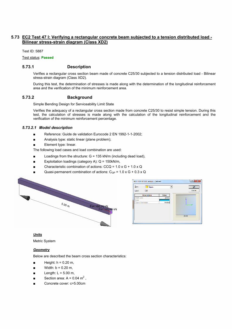
5.73 EC2 Test 47 I: Verifying a rectangular concrete beam subjected to a tension distributed load - Bilinear stress-strain diagram (Class XD2)
Test ID: 5887
Test status: Passed
5.73.1 Description
Verifies a rectangular cross section beam made of concrete C25/30 subjected to a tension distributed load - Bilinear stress-strain diagram (Class XD2).
During this test, the determination of stresses is made along with the determination of the longitudinal reinforcement area and the verification of the minimum reinforcement area.
5.73.2 Background
Simple Bending Design for Serviceability Limit State
Verifies the adequacy of a rectangular cross section made from concrete C25/30 to resist simple tension. During this test, the calculation of stresses is made along with the calculation of the longitudinal reinforcement and the verification of the minimum reinforcement percentage.
5.73.2.1 Model description
■ Reference: Guide de validation Eurocode 2 EN 1992-1-1-2002;
■ Analysis type: static linear (plane problem);
■ Element type: linear.
The following load cases and load combination are used:
■ Loadings from the structure: G = 135 kN/m (including dead load),
■ Exploitation loadings (category A): Q = 150kN/m,
■ Characteristic combination of actions: CCQ = 1.0 x G + 1.0 x Q
■ Quasi-permanent combination of actions: CQP = 1.0 x G + 0.3 x Q
Units
Metric System
Geometry
Below are described the beam cross section characteristics:
■ Height: h = 0.20 m,
■ Width: b = 0.20 m,
■ Length: L = 5.00 m,
■ Section area: A = 0.04 m2 ,
■ Concrete cover: c=5.00cm

ADVANCE VALIDATION GUIDE
681
Materials properties
Rectangular solid concrete C25/30 and S500, class A reinforcement steel is used. The following characteristics are used in relation to this material:
■ Exposure class XD2
■ Concrete density: 25kN/m3
■ Stress-strain law for reinforcement: Bilinear stress-strain diagram
■ The concrete age t0=28 days
■ Humidity RH=50%
Boundary conditions
The boundary conditions are described below:
■ Outer:
► Support at start point (x=0) , fixed connection,
► Support at end point (x = 5.80) restrained in translation along Z.
■ Inner: None.
Loading
The beam is subjected to the following load combinations:
Load combinations:
■ Characteristic combination of actions:
KNQGN cq,ser 285150135
■ Quasi-permanent combination of actions:
KN*.Q*.GN qp,ser 1801503013530
5.73.2.2 Reference results in calculating the longitudinal and the minimum reinforcement
Calculating the longitudinal reinforcement for serviceability limit state:
S
sersers
NA
,
Mpaf yks 400500*8,0*8,0
²13.7²10*13.7400
285.0 4, cmmA sers
Calculating the minimum reinforcement:
²04.020.0*20.0 mAc
²05.2500
56.2*04.0* cm
f
fAA
yk
ctmcs
Finite elements modeling
■ Linear element: S beam,
■ 6 nodes,
■ 1 linear element.
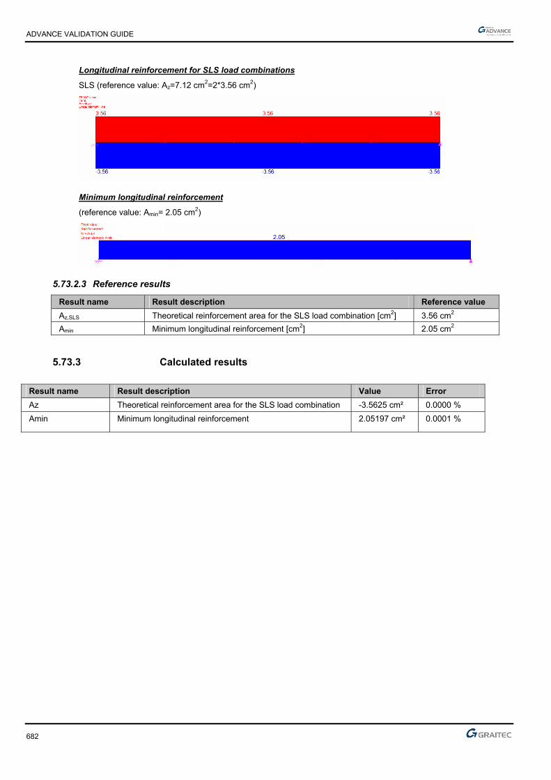
ADVANCE VALIDATION GUIDE
682
Longitudinal reinforcement for SLS load combinations
SLS (reference value: Az=7.12 cm2=2*3.56 cm2)
Minimum longitudinal reinforcement
(reference value: Amin= 2.05 cm2)
5.73.2.3 Reference results
Result name Result description Reference value
Az,SLS Theoretical reinforcement area for the SLS load combination [cm2] 3.56 cm2
Amin Minimum longitudinal reinforcement [cm2] 2.05 cm2
5.73.3 Calculated results
Result name Result description Value Error
Az Theoretical reinforcement area for the SLS load combination -3.5625 cm² 0.0000 %
Amin Minimum longitudinal reinforcement 2.05197 cm² 0.0001 %


031514-0409-0418