advanced accelerator concepts - stanford university · pdf fileadvanced acce le rat0 ... luke...
TRANSCRIPT
Advanced Accelerator Concepts
Lecture 15
Dr Dave Whittum
May 221998
Advanced Acce le rat0 r Research
1 High-Gradient Acceleration amp You
2 A High Gradient Collider Concept
3 Proof-of - P ri nci ple Experi men ts
STANFORD UNIVERSITY
S L A C
httpllwwwslacstanfordedulgrplarb
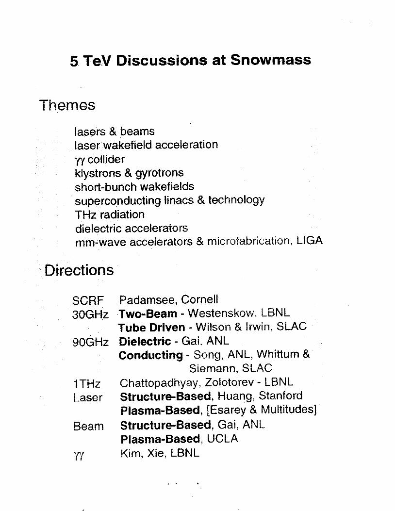
5 TeV Discussions at Snowrnass
Themes
lasers amp beams
yy collider klystrons amp gyrotrons short-bunch wakefields superconducting linacs amp technology THz radiation dielectric accelerators mm-wave accelerators tk microfabrication LlGA
akefieid acceleration
Directions
SCRF 30GHz
SOGHz
I THz Laser
Beam
Padarnsee Cornell Two-Beam - Westenskow L B N t Tube Driven - Wilson amp Irwin SLAC Dielectric - Gai ANL Conducting - ANL Whitturn 8t
Siemann SLAC Chattopadhyay Zolotorev - LBNL Structu re-Based ti uang Stanford Plasma-Based [Esarey amp Multitudes] Structure-Based Gai ANL Plasma-Based UCLA Kim Xie LBNL
-
1010 hb td Q) 1 0 8 a
106
104
102
1 oo
The Frontier is the Acce le rat0 r
I I I I I t I I I I I I I
1900 1950 2000 2050 2100 2150 2200 Year
Gradient amp Wavelength Today
10
E 101 s 3 100 I
0 1 0 -l
10 -2 10 -3 10 -2 10 -1 10 O 10 10
mi I I i meter wave microwave
plasma - slac-pu b-7805
Problems for a Col I ider
site power
charge heating emittance wakefields luminosity
magnets
field emission breakdown structure damage instrumentation backgrounds positrons polarization
reliability sociology economics international partners graduate students
Exercise No 1 Devise solutions to all problems at 1 GeVIm 5 TeV c0m
Snowmass lsquo96
Neutral Beam or yy Collisions
e - amp e + e e- amp e+
charge separation instability
A - - 1 I p-+ I +
I I
5
slac-pub-7808
s 1
I 1
t - 9
dt W T
ampe
t-2 = - c) L
_ L -
d 1
1 0
c- 8Vnymd - - - -
- Or4 66 08 1 - -
I
p I _ 7
-
lt
A
gt
Figure 2 Centroid separation wnnaiized to the initial offset for the right moving beams that were initially offset The circles are from the simulation and the solid curve is the analytical result
LA
~ 1 1
100
i 1
I 011 -03 -06 -02 0 yL
Figurz 3 Centroid separation normalized to the initial offset for the left moving beams that were not offset inirially The circles are from the simulation and the solid curve is the analytical result
The separation of the left moving beams for this case is
Tmse two m n s be complnad with simdstiorr msdts Fistlres 2 and 3 show rhe results for rhe case of for D = 5 and 2 A h r = 005 The simulation aad calculation are in good agreement We consider this to indicate that the simulation is correct and can be used to study tolerances for realistic situations including Gaussian profiles and unequal charges
4 C O N C L U S I O N S
Collision of neutral beams permits operation in a region of IP parameter space that for simple M- collisions wouldmrrcspond to Y 6 gtgt I With neutral beams much larger emittances higher bunch charges and shorter wavelength linacs may be contemplated Control of 25 TeV neutral beams in collision are likely to require an uncompensated disruption parameter D lt 10 md a correspondingly short bunch len-mh
We have dewbped and tested a simulation that can be used to make quantitative estimates of tolerances in neuual beam collisions
REFERENCES [I] Robert N Cahn and Gerson Goldkber The
Experillsebtal Foundations of Particle Physics (Cambridge University Press Cambridge 1989)
[2] Proceedings of rhe 1996 DPBDPFWorkshop on New Directions for High Energy Physics (AIP New York to be published)
[3] R Hollebeek Nuci Instrum Meth 184 (1981) 33 G Bonvicini et al Phys Rev Lett 6 2 (1989) 3381
[4] P Chen and V Telnov Phys Rev Lett 6 3 (1989) 1796
[5] K Brown Conceptual Design of Final Focus Sys t em for Linear Colliders in Fontiers of Particle Beams M Month and S Turner (eds) Lecture Notes in Physics (Springer-Verlag Xew York 1983) pp 431-494
[6] D Whittum E Henke and P J Chou (rhs2 proceedings)
[7l K Oide PhTs Rev Len 61 (1988) 1713 [SI V E B a l a h and N A Solyak Proc XI11 e
Inrenmonal Conference oil High Eixrgi Accelerators Novosibirsk USSR 1986
[9] J B Rosenzweig B Autin and P Chen Proc 989 Luke Arrowhad Workshop on Advanced iiccelemor Concepts
[IO] S Krishnagopal and R Siemann Phys Rev Let 67 2461 (1991)
[ I 11 B Podobebov and R H Siemann Phys Rev E 5 2 3066 (1995)
Note that the last two equations are exact solutions
Synchrotron Radiation
10 n
E E 0 -
o W
-
-
-20 I -20 -10 0 10 20
x (nm)
h -10
1 2
1 0
0 8
0 6
0 4
0 2
0 0 1
i i
-20 4 -20 -10 0 10 20
x (4
I
1 0 7 E~ (m-rad)
rl rl rl r(
0
n
E W
cl
099
104
103
102
I I I - I I
I - I I I
I I Unloaded -
Final Focus
E (GeV)
098 s
097
096
I I I I I I I
Beam I
I I
I I I I I I I I I I I
I I I 1 I I 2
095 -1 0 - 0 5 00 05 10 1 5 0
tT
slac-pu b-774 1
Harmonic Acceleration 1 oo
099
098
097
096
I I I I --_ I
I I I I
Beam
I I I I I 095
-1 0 -0 5 0 0 05 tT
10 15 20
0-
0-
1 00
2
1
10- -1
-2 10- 0 0 0 2 04 06 0 8 1 o
tT
24 n
W
-
16 I I I 1 I I
0 5 10 15 20 25 30 6 (10-5)
Fig 6 Energy bandwidth for the final-focus optics of Fig 5 as obtained from a tracking simulation with the program MADrdquo
24 Earmonic Acceleration
As discussed in the previous section without sextupole correction the control of the chromatic spot-size increase requires a very small energy spread across each bunch We may attain this energy spread by employing rf acceleration sections operated at harmonics of the fundamental The energy kick imparted by a linac with harmonic acceleration and single-bunch beam loading takes the forin
v(t) = vh cos(hwlt+ $ I ) - dtrsquo ~ ( t rsquo ) ~ ~ ~ rsquo - l ( t - tlsquo) (14) h J
with V bhe angular frequency for the fundamental The function Wl describies the longitudinai wakefield of the linac and I gt 0 the bunch current waveform For the sake G definiteness iec us consider a model wakefield varying with tiine as JV-J x t-ldquo sud a -9ix-t-ioplsquo current profile turning on at t = 0 and extending to t = T with tom1 charge Q
For the case of a single harmonic thc ftndamental voae aiid the xakefield may be expressed as
the voltage and phase for the harinonic h i 1 ~ 1
Vr( t ) = COS(Ult+ 0) - dtrsquo Itrsquo)lv-$ - KI (15)
the total voltage is V ( t ) = VL(t) + F C O S ( h w l t i h) (16)
We wish to select the amplitude and phase of the harmonic rf Vtl and l j h such that
the rins voltage is minimized In terms of
gtE dC + ids ( 1 i ) SE = e i h ~ l t - lt e i h ~ l t dV(t) = V ( t ) - lt v gt
one may express the optimal phasc as
Im(lt dV d E gtlt bC ciE gt) hi(lt bV dE gtlt bS dE- gt)
$5 = tan-
and the amplitude as lt d V sc gt lt bc gt
V = -
This is approximately ViVl x -lh2 In Eqs (li)-(19) lt gt denotes an average over the bunch and dC and 65 are the real and imaginary p u t s of dE respectively
As an example we take v = 05 and h = 10 In this case by op~iniiiing rhc threc parameters fundamental inode phuc harmonic phase ltand liariiionic amplitude it is possible to achieve an rms energy spread of 16 x with a iioririalized harmonic amplitude of 12 x lo- If one excludes the front 5 of thc beam thc energy spread drops to 39 x 10-I excludiiig the front 10 it is ony 14 x lo- close to the required value Adding a third frequency (h z 30) and opLimizing its phase and amplitude as well the energy spread can be further reduced to 9 x excluding the front 5 of the beam and to 35 x excludiug the front 10 Figurc 7 coinpares thc loaded and unloaded waveform that can bc ittained in a conventioiial single-frequency linac with those for a two and tliree frequency linac
The tot rf input energy per pulse for all harmonic sections togehe 2s a fraction of riiar fo rhe fundmiental mode rf system is
25 Charge Conzpensator
Tie ia-out of tie switched ini7iiih accclermr can be a r rxged such lei eectron and p o ~ i i ~ o n Dunciies are copiopitgnting iii parallel tiannes 7vhich 2re separated -- vtiicaiiy r by about 3 iiini as illussraced in Fig 1 111 she Sua1 focils die pairs of co-pxpagating buiiches can ihcii be coiiibiued into singe iieutrai bunches As s txed h e h e tile motimtion for this charge compeiisatio is to reduce the energy OS dio to beamstr~hlunnl
Tie Iombiiiitiion of eectroii and positron buiichcs is accompishcd using a mag- netic half-chicane consisting of two successive vertical bending magnets each of length io and with opposite deflection angles X B and bending radii f p = amp108
All-Beam Collisions Cluster Collision
H-Chicane I
r
2500 m
Multiplexed Collisions
Triplets
V-Chicane -
1300 m 250 m
Half-Chicane - - -
Crab Triplets Injector Matrix Linac Collimation Cavities
4 b 4 b 25 km 150 m
IR
e f I - a I E 0 m (rs
E 0 0 m 1
I I E 0 0 m N I
I
cl
lsquok e
250
200-
- 150 8
250
200
150
I
I lsquo (4
I I
I 8 lsquo - 1
I
- - - - - --- - - - - _ _ I I (d fix I
I I
1
Fig 12 Horizontal and vertical beta functions caculated from he interactioc point bxkwards through the final triplet for an energy deviation relative to the design optiw of (a) -IO (b) -5 and (c] 0 T h e IP beta fiinctions are held constant a 8y z 150 LE
1 a 8 a a a a a I a a 1
I I I I
0 0 m
0 0 N
0 0 T-
O rn
0
I oo I I 0YY -
0 Y R - gt 3 097 - -
1196 -
0 Y S -10 4 5 01) 05 10 15 20
VI
0 Y Y
gt 5
I - - - I
I I
j Unloidrd 1 - I
I I
2 I o - J
I 1 0 - 5 - - $ 0 1 0 0 - v)
I IO -
- 2 01 04 06 0R 10
vr Fig 7 Loaded and unloaded voltage waveforms for a wakefield parameter v = 05 (a) in a conventional single frequency linac with a total rms energy spread of Srms (b) in a two frequency linac with S excluding the first 10 of the beam (shown here is the difference from the average voltage note the magnified scale)
16 x (c) in a three frequency linac with 6 = 25 x
If the initial vertical separation of the electron and positron bunches is Ay the condition for beam combining in the half-chicme is
(21)
The miminum length of the bending magnets is deterinined by the einittauce growth due to synchrotron radiation an effect which was analyzed by Sands12 Crosbie12 and Spence14 and by the induced energy spread In the limit of many photoiis (ea- gtgt 1 with cy z 1137 the fine structure constant) the emittance at the end of the half chicane (for zero initial emittance) is
For = 3 x lo6 this amounts to
(32)
(33)
If we restrict the emittance growth to a value not larger than -er 5 m rad
i
Table 1 IP beam parameters for a W-band h e a r collider The abbreviation neutr stands for neutralization t e charge ComDensation
symbol
E
v
parameter scheme k scheme ZZ cluster collision multiplexing
25 TeV beam energy charge per bunch at ZP particles per bunch number of equal-charge bunches
number of collisions per bunch number of species per bunch
hor bunch separation in linac bunch-bunch time separation longitudinal bunch spacing repetition frequency average beam power (per side) rns bunch length rxns intrabunch energy spread horizontal emittance vertical emittance hor euroP spot size vert IP spot size hor I diver uence vert P divergence hor euroP Seta function vert IP beta function average hac Sera fimction disrup ticn parwieterccllisicn
hewistr parameter wo neutr beanis 30 OF photonselectron
collision wo iieutr beamarrahiung average energy
loss ncllision wo neuer total iuninosiv phch k -A- G Qide eEect Sr w ne1itr
per pulse
(+ir = 2 means neutralization)
e 11- d C L L 1
720 pC 60 pC 45 x io9 375 x 108
a
1 1 or 2
14 mm 300 ps 9 a n
130 Hz 07 MW 30 P a
10-5 100 nm 100 11111 17 Ul
17 Lull 115 prad 1 1 3 mad 150 pm 130 p l u
25 lu 262
200 0S
loo
25
25 a
30 ps 6 m m
22
16 1s
440
Matrix Linac
0
primary 0 0
0 0 0
0
0 0
0
0 OaO 0 0 0 e0 0
0 0 0
0
parallel beamlines
primary transmission line
0 secondary transmission lines I f i c
L t Y Y 0 0 0
t
e - I e -
L 4-- c
3 2 3 M
c13 l A L
I
Circuit Model
primary
e - I e
0 a 0
I n=l n=2 n=3 u v---
~~ VR+- I n v n v3 A
i X
IVI
1 4
1 2
1 0
0 8
0 6
0 4
0 2
0 0 0 0 2 0 4 0 6 0 8 1
t(ns)
1 2
1 0
0 8
0 4
0 2
0 0
1 3
1 2
- E 1 1
1 0 M 8 0 9
0 8
- +
Dispersion attenuation tapering amp beam-loading
0 1 2 4 5 t(ns
1 1 1 1
lsquoI 0 7
0 1 0 2 0 3 0 4 0 5 0 cell number
Cell Design v00
Y
[RQ]=I 44 Ohm Qw=2300
goal is
[RQ]=221 Ohm Qw=2700
Matched Test Section
o 1
Y
I
0
8 b 8 8 9 0 9 2 9 4 9 b
f(GHz)
Wa kef i e I ds
60 pC bunches 15 m pat 10 GeV small aperture miniature magnets
1 0 1
dx 0
L=60 cm Injection at 10 GeV Unit Offset 16 m initial beta scaled inversely with energy
numerical
1 0 0 00 05 10 20 25
z(krnrsquo
t
i
1 09
I 03
xxa 02
1 0
1 00
I I I I 1 I
Ls60 cm Inection at 10 GeV Unit Offset k o 1attice
rC I 1
~
0 5 1 0 15 2 0 2 5 0 0
z(km)
FIG-URG 1 Comparison of the steepest-descents result with simulation for the case of a perfectly aligned linac and an initial beam offset No focusing lattice is present
L=60 cm Injection a1 18 GeV Constant Sinusoid amp Random Offsets No Lattice
-uniform -100 m sinusoid -10 m sinusoid
1 03 random (05m)
i _ - _
- ________
I
0 5 10 1 5 2 0 2 5 1 00 0 0
O m )
FIGURE 2 Results of simulation for a variety of linac structure misalignments uniform offset by x sinusoidal offsets d 100 m and 10 m wavelength with amplitude x and random offsets every 05 m with amplitude x
A Study oE a Planar ampWire Quadwpole Magaet Design
Abstract Thc use of simple cumnt carrying wires embedded in a silicon subsuate laas kcn posed for the puqwsc of quabpole focusing A srmll t t d y has do to show that fyld is quite lierr d that Ibe field sotngth is ampiWt for f- Mug a qeick oprimisation of the wire gcmnw diamp E n c u i y wasfouod~to -1 a d the field padicnt warr found to be 30 Tm using a peak current of 20 A
ReAection and Transmission for First ARDB W-Band Structure 1
09
08
07
5 06 II +
- cu - -- 05
II 04
03
- - nrsquo
0
02
01
I 1 I
06 88 90 92 94 96 98 0 a4
Frequency ( G W
z e u = - c
c
I
c 3 8
Power Source Secondaries
e- I e- e-
1 0 7
1 L=150 cm 1 1 0 6 s
J
1 0 4
1 0 3 1 o 2 0 3 0 4 0 5 0 6 0
slac-pu b-7809
section of a cylindrical diode 480kV 300A
cm- of x75 pasduces 7 H ) A I C d at mode convergeace Q 8 c~rrespoads 80
f 400 hrlf-mgle 1247cm cathode radius 0154 cm mode radius
5iamphr 7 5 dk hput S W requiw4IPW source to keep gain UDamp 98d
lkmampamp rmdb vi WRlO taper and comer reflector ma- cut off to RF
C oll t c t or coasideriag dispersing beam on side-wall with the help of a sbort q d focusing in tbe ve at lOHz l5OJ beam dispersed over 5cm in t
and 4cm in x cmesponds to 4 O W c d
Output power in cxccss for tube U1 VSWRltWeuroE to inhibit oscillation
106
EEV
varian Canada microwave products
MILLIMETER WA VE POWER MODULE
Ihe -82783 series of Miniaturized Millimeter Wave Power
Module u e ideal for airborne urd mobile applications
lhese modules are 8 ComPIct h i h power alternative where
solid UIte souras CIIlllOt provide RF power at high
ampkiency Efficiencies over 10 times that of solid stae can
be achieved with expected life times of 5 - 10 years The
s d l fbotprint power module is under development Please
call Varian for details
PERFORMANCE
ELECTRICAL MECHANICAL
FREQUENCY 0 WEIGHT 7 Ibs PEAK OUTPUT POWER 0 DIMENSIONS- - 3 118 x 3 718 x 9 In- AVERAGE POWER WAVEGUIDE WR 10 (OS0 X I O 0 ins) BANDWIDTH 10 GHz FLANGE UG-387N-modified GAIN COOLING FORCED AIR PRF PULSE WIDTH DUTY PRIME POWER 270 V DC
amp ~ - _ - - - - -
variana
( R E G I S T E R E D I
- I
9 oc
rp
T 0 c
0
H
f
i
z c 0 u
f f 0
E euro
v m d
I
I
f
I
I I I 1 I
i I
I
4 I 1
i I
1 t
I
0 - d k
H n
+
A I
k a
4 u X 0
-I=- d O k 4 0 as
a 0 0
0 0 v-
0 00
0 0 s cu 0 co
_
0 0 d-
I I
0
3
25
2 -
15
1 -
05
0
I 1 1 I
DDS - S f d w z 1 - 0 -
b 0
b 0
(I b 0
b b
b e b
0 b o b - b
b
b b b
b - b
b - b - b
0 - -
- - - e - - - - -
0 -
I I I I 1 I
I
100
50
0 -
-
-
0 i
e 0
e 0
-150 I 6 I I I
-60 -40 -20 0 20 40 60 80 100
beam posiition um
ACCL1560
Mew +via ACCL 1 660
TOR01750
WIRE1950 PROFlO
Proof-of-Principle Experiments
mm-wave structure Dennis Palmer fabrication amp bonding bench measurement
Ping Chou 4 samp
com posi te structures Eddie Lin design bonding of Cu and Diamond
active circuits Sami Tantawi switch test - bench amp high-power
mm-wave source klystrino high-power tube two-beam accelerator
FNW 4 Eric Colbv
structure studies with beam wa kef ie Id i nst ru men t sub-harmonic drive
high-power studies pulsed heating field emission breakdown
Liqun So ig amp Jeff Li c uta) Randy Fowkes amp The Klystron Dept
Marc Hill IHAPGIPPb) amp The NLCTA Mike Seidel 4 PS y
David Pritzkau Lisa Laurent CIKD) Glenn Scheitrum amp The Klystron Dept
Dennis Palmer 1 GeV - I m Test Linac End Station B
harmonic acceleration THz linac plasma acceleration laser linac
amp EFD
(tune in next week)
I
0) c S 0
Q) a
I
E
I
I I (Ib (Ib 4)
4 0 0 I __ c
I
I L= v) f = a o c I + 520
+ Q) 5 I 9 i~ Y
2 - K a 2 b K o h 0 2 0 0 =E zg
CI c 0
CI 0 Q) z
+--- -j
=
CI E s
z
~~~~
-I 0
v) v) Q) 0
2 0
The Reach of High Energy Physics is limited by its instruments
accelerators
Today m245 60-M W klystrons running af 120 Hz fo power a Two-Mile Linac producing 4000 Zrsquos per
Two 2200 m rings being commissioned for a B-Factory
day
Next Week Bring Worked Exercises Exercise No 1 Devise solutions to all problems at 1 GeVm 5 TeV com Exercise No 2 Devise Proof-of-Principle Experiments
Radio convezaation released hy the Chief of Naval Operat ions 40 - 1 - 9amp+
Americans to avoid a collision
Pleaae ampvert your m u s e 15 degrees to the North
Canadians Recommend you divert YOUR course 15 degrees to the South to avoid a collision
Americans This is the Captain of a US Navy ship I say again divert YOUR course
Canadians No f bay again you divert YOUR course
Americans THIS IS TFEE AIRCRAFT CARRIER USS LINCOLN THE SECOND LARGEST SHIP IN THE UNITED STATES ATLANTIC FLEET WE ARE ACCOMPANIED BY THREE DESTROYERS THREE CRUISERS AND NUMEROUS SUPPORT VESSELS I DEMAND THAT YOU CHANGE YOUR COURSE 15 DEGREES NORTH THATS ONE FIVE DEGREES NORTH OR COUNTER-MEASURES WILL BE UNDERTAKEN TO ENSURE THE SAFETY OF THIS SHIP
Canadians This is a lighthouse Your call

Advanced Acce le rat0 r Research
1 High-Gradient Acceleration amp You
2 A High Gradient Collider Concept
3 Proof-of - P ri nci ple Experi men ts
STANFORD UNIVERSITY
S L A C
httpllwwwslacstanfordedulgrplarb
5 TeV Discussions at Snowrnass
Themes
lasers amp beams
yy collider klystrons amp gyrotrons short-bunch wakefields superconducting linacs amp technology THz radiation dielectric accelerators mm-wave accelerators tk microfabrication LlGA
akefieid acceleration
Directions
SCRF 30GHz
SOGHz
I THz Laser
Beam
Padarnsee Cornell Two-Beam - Westenskow L B N t Tube Driven - Wilson amp Irwin SLAC Dielectric - Gai ANL Conducting - ANL Whitturn 8t
Siemann SLAC Chattopadhyay Zolotorev - LBNL Structu re-Based ti uang Stanford Plasma-Based [Esarey amp Multitudes] Structure-Based Gai ANL Plasma-Based UCLA Kim Xie LBNL
-
1010 hb td Q) 1 0 8 a
106
104
102
1 oo
The Frontier is the Acce le rat0 r
I I I I I t I I I I I I I
1900 1950 2000 2050 2100 2150 2200 Year
Gradient amp Wavelength Today
10
E 101 s 3 100 I
0 1 0 -l
10 -2 10 -3 10 -2 10 -1 10 O 10 10
mi I I i meter wave microwave
plasma - slac-pu b-7805
Problems for a Col I ider
site power
charge heating emittance wakefields luminosity
magnets
field emission breakdown structure damage instrumentation backgrounds positrons polarization
reliability sociology economics international partners graduate students
Exercise No 1 Devise solutions to all problems at 1 GeVIm 5 TeV c0m
Snowmass lsquo96
Neutral Beam or yy Collisions
e - amp e + e e- amp e+
charge separation instability
A - - 1 I p-+ I +
I I
5
slac-pub-7808
s 1
I 1
t - 9
dt W T
ampe
t-2 = - c) L
_ L -
d 1
1 0
c- 8Vnymd - - - -
- Or4 66 08 1 - -
I
p I _ 7
-
lt
A
gt
Figure 2 Centroid separation wnnaiized to the initial offset for the right moving beams that were initially offset The circles are from the simulation and the solid curve is the analytical result
LA
~ 1 1
100
i 1
I 011 -03 -06 -02 0 yL
Figurz 3 Centroid separation normalized to the initial offset for the left moving beams that were not offset inirially The circles are from the simulation and the solid curve is the analytical result
The separation of the left moving beams for this case is
Tmse two m n s be complnad with simdstiorr msdts Fistlres 2 and 3 show rhe results for rhe case of for D = 5 and 2 A h r = 005 The simulation aad calculation are in good agreement We consider this to indicate that the simulation is correct and can be used to study tolerances for realistic situations including Gaussian profiles and unequal charges
4 C O N C L U S I O N S
Collision of neutral beams permits operation in a region of IP parameter space that for simple M- collisions wouldmrrcspond to Y 6 gtgt I With neutral beams much larger emittances higher bunch charges and shorter wavelength linacs may be contemplated Control of 25 TeV neutral beams in collision are likely to require an uncompensated disruption parameter D lt 10 md a correspondingly short bunch len-mh
We have dewbped and tested a simulation that can be used to make quantitative estimates of tolerances in neuual beam collisions
REFERENCES [I] Robert N Cahn and Gerson Goldkber The
Experillsebtal Foundations of Particle Physics (Cambridge University Press Cambridge 1989)
[2] Proceedings of rhe 1996 DPBDPFWorkshop on New Directions for High Energy Physics (AIP New York to be published)
[3] R Hollebeek Nuci Instrum Meth 184 (1981) 33 G Bonvicini et al Phys Rev Lett 6 2 (1989) 3381
[4] P Chen and V Telnov Phys Rev Lett 6 3 (1989) 1796
[5] K Brown Conceptual Design of Final Focus Sys t em for Linear Colliders in Fontiers of Particle Beams M Month and S Turner (eds) Lecture Notes in Physics (Springer-Verlag Xew York 1983) pp 431-494
[6] D Whittum E Henke and P J Chou (rhs2 proceedings)
[7l K Oide PhTs Rev Len 61 (1988) 1713 [SI V E B a l a h and N A Solyak Proc XI11 e
Inrenmonal Conference oil High Eixrgi Accelerators Novosibirsk USSR 1986
[9] J B Rosenzweig B Autin and P Chen Proc 989 Luke Arrowhad Workshop on Advanced iiccelemor Concepts
[IO] S Krishnagopal and R Siemann Phys Rev Let 67 2461 (1991)
[ I 11 B Podobebov and R H Siemann Phys Rev E 5 2 3066 (1995)
Note that the last two equations are exact solutions
Synchrotron Radiation
10 n
E E 0 -
o W
-
-
-20 I -20 -10 0 10 20
x (nm)
h -10
1 2
1 0
0 8
0 6
0 4
0 2
0 0 1
i i
-20 4 -20 -10 0 10 20
x (4
I
1 0 7 E~ (m-rad)
rl rl rl r(
0
n
E W
cl
099
104
103
102
I I I - I I
I - I I I
I I Unloaded -
Final Focus
E (GeV)
098 s
097
096
I I I I I I I
Beam I
I I
I I I I I I I I I I I
I I I 1 I I 2
095 -1 0 - 0 5 00 05 10 1 5 0
tT
slac-pu b-774 1
Harmonic Acceleration 1 oo
099
098
097
096
I I I I --_ I
I I I I
Beam
I I I I I 095
-1 0 -0 5 0 0 05 tT
10 15 20
0-
0-
1 00
2
1
10- -1
-2 10- 0 0 0 2 04 06 0 8 1 o
tT
24 n
W
-
16 I I I 1 I I
0 5 10 15 20 25 30 6 (10-5)
Fig 6 Energy bandwidth for the final-focus optics of Fig 5 as obtained from a tracking simulation with the program MADrdquo
24 Earmonic Acceleration
As discussed in the previous section without sextupole correction the control of the chromatic spot-size increase requires a very small energy spread across each bunch We may attain this energy spread by employing rf acceleration sections operated at harmonics of the fundamental The energy kick imparted by a linac with harmonic acceleration and single-bunch beam loading takes the forin
v(t) = vh cos(hwlt+ $ I ) - dtrsquo ~ ( t rsquo ) ~ ~ ~ rsquo - l ( t - tlsquo) (14) h J
with V bhe angular frequency for the fundamental The function Wl describies the longitudinai wakefield of the linac and I gt 0 the bunch current waveform For the sake G definiteness iec us consider a model wakefield varying with tiine as JV-J x t-ldquo sud a -9ix-t-ioplsquo current profile turning on at t = 0 and extending to t = T with tom1 charge Q
For the case of a single harmonic thc ftndamental voae aiid the xakefield may be expressed as
the voltage and phase for the harinonic h i 1 ~ 1
Vr( t ) = COS(Ult+ 0) - dtrsquo Itrsquo)lv-$ - KI (15)
the total voltage is V ( t ) = VL(t) + F C O S ( h w l t i h) (16)
We wish to select the amplitude and phase of the harmonic rf Vtl and l j h such that
the rins voltage is minimized In terms of
gtE dC + ids ( 1 i ) SE = e i h ~ l t - lt e i h ~ l t dV(t) = V ( t ) - lt v gt
one may express the optimal phasc as
Im(lt dV d E gtlt bC ciE gt) hi(lt bV dE gtlt bS dE- gt)
$5 = tan-
and the amplitude as lt d V sc gt lt bc gt
V = -
This is approximately ViVl x -lh2 In Eqs (li)-(19) lt gt denotes an average over the bunch and dC and 65 are the real and imaginary p u t s of dE respectively
As an example we take v = 05 and h = 10 In this case by op~iniiiing rhc threc parameters fundamental inode phuc harmonic phase ltand liariiionic amplitude it is possible to achieve an rms energy spread of 16 x with a iioririalized harmonic amplitude of 12 x lo- If one excludes the front 5 of thc beam thc energy spread drops to 39 x 10-I excludiiig the front 10 it is ony 14 x lo- close to the required value Adding a third frequency (h z 30) and opLimizing its phase and amplitude as well the energy spread can be further reduced to 9 x excluding the front 5 of the beam and to 35 x excludiug the front 10 Figurc 7 coinpares thc loaded and unloaded waveform that can bc ittained in a conventioiial single-frequency linac with those for a two and tliree frequency linac
The tot rf input energy per pulse for all harmonic sections togehe 2s a fraction of riiar fo rhe fundmiental mode rf system is
25 Charge Conzpensator
Tie ia-out of tie switched ini7iiih accclermr can be a r rxged such lei eectron and p o ~ i i ~ o n Dunciies are copiopitgnting iii parallel tiannes 7vhich 2re separated -- vtiicaiiy r by about 3 iiini as illussraced in Fig 1 111 she Sua1 focils die pairs of co-pxpagating buiiches can ihcii be coiiibiued into singe iieutrai bunches As s txed h e h e tile motimtion for this charge compeiisatio is to reduce the energy OS dio to beamstr~hlunnl
Tie Iombiiiitiion of eectroii and positron buiichcs is accompishcd using a mag- netic half-chicane consisting of two successive vertical bending magnets each of length io and with opposite deflection angles X B and bending radii f p = amp108
All-Beam Collisions Cluster Collision
H-Chicane I
r
2500 m
Multiplexed Collisions
Triplets
V-Chicane -
1300 m 250 m
Half-Chicane - - -
Crab Triplets Injector Matrix Linac Collimation Cavities
4 b 4 b 25 km 150 m
IR
e f I - a I E 0 m (rs
E 0 0 m 1
I I E 0 0 m N I
I
cl
lsquok e
250
200-
- 150 8
250
200
150
I
I lsquo (4
I I
I 8 lsquo - 1
I
- - - - - --- - - - - _ _ I I (d fix I
I I
1
Fig 12 Horizontal and vertical beta functions caculated from he interactioc point bxkwards through the final triplet for an energy deviation relative to the design optiw of (a) -IO (b) -5 and (c] 0 T h e IP beta fiinctions are held constant a 8y z 150 LE
1 a 8 a a a a a I a a 1
I I I I
0 0 m
0 0 N
0 0 T-
O rn
0
I oo I I 0YY -
0 Y R - gt 3 097 - -
1196 -
0 Y S -10 4 5 01) 05 10 15 20
VI
0 Y Y
gt 5
I - - - I
I I
j Unloidrd 1 - I
I I
2 I o - J
I 1 0 - 5 - - $ 0 1 0 0 - v)
I IO -
- 2 01 04 06 0R 10
vr Fig 7 Loaded and unloaded voltage waveforms for a wakefield parameter v = 05 (a) in a conventional single frequency linac with a total rms energy spread of Srms (b) in a two frequency linac with S excluding the first 10 of the beam (shown here is the difference from the average voltage note the magnified scale)
16 x (c) in a three frequency linac with 6 = 25 x
If the initial vertical separation of the electron and positron bunches is Ay the condition for beam combining in the half-chicme is
(21)
The miminum length of the bending magnets is deterinined by the einittauce growth due to synchrotron radiation an effect which was analyzed by Sands12 Crosbie12 and Spence14 and by the induced energy spread In the limit of many photoiis (ea- gtgt 1 with cy z 1137 the fine structure constant) the emittance at the end of the half chicane (for zero initial emittance) is
For = 3 x lo6 this amounts to
(32)
(33)
If we restrict the emittance growth to a value not larger than -er 5 m rad
i
Table 1 IP beam parameters for a W-band h e a r collider The abbreviation neutr stands for neutralization t e charge ComDensation
symbol
E
v
parameter scheme k scheme ZZ cluster collision multiplexing
25 TeV beam energy charge per bunch at ZP particles per bunch number of equal-charge bunches
number of collisions per bunch number of species per bunch
hor bunch separation in linac bunch-bunch time separation longitudinal bunch spacing repetition frequency average beam power (per side) rns bunch length rxns intrabunch energy spread horizontal emittance vertical emittance hor euroP spot size vert IP spot size hor I diver uence vert P divergence hor euroP Seta function vert IP beta function average hac Sera fimction disrup ticn parwieterccllisicn
hewistr parameter wo neutr beanis 30 OF photonselectron
collision wo iieutr beamarrahiung average energy
loss ncllision wo neuer total iuninosiv phch k -A- G Qide eEect Sr w ne1itr
per pulse
(+ir = 2 means neutralization)
e 11- d C L L 1
720 pC 60 pC 45 x io9 375 x 108
a
1 1 or 2
14 mm 300 ps 9 a n
130 Hz 07 MW 30 P a
10-5 100 nm 100 11111 17 Ul
17 Lull 115 prad 1 1 3 mad 150 pm 130 p l u
25 lu 262
200 0S
loo
25
25 a
30 ps 6 m m
22
16 1s
440
Matrix Linac
0
primary 0 0
0 0 0
0
0 0
0
0 OaO 0 0 0 e0 0
0 0 0
0
parallel beamlines
primary transmission line
0 secondary transmission lines I f i c
L t Y Y 0 0 0
t
e - I e -
L 4-- c
3 2 3 M
c13 l A L
I
Circuit Model
primary
e - I e
0 a 0
I n=l n=2 n=3 u v---
~~ VR+- I n v n v3 A
i X
IVI
1 4
1 2
1 0
0 8
0 6
0 4
0 2
0 0 0 0 2 0 4 0 6 0 8 1
t(ns)
1 2
1 0
0 8
0 4
0 2
0 0
1 3
1 2
- E 1 1
1 0 M 8 0 9
0 8
- +
Dispersion attenuation tapering amp beam-loading
0 1 2 4 5 t(ns
1 1 1 1
lsquoI 0 7
0 1 0 2 0 3 0 4 0 5 0 cell number
Cell Design v00
Y
[RQ]=I 44 Ohm Qw=2300
goal is
[RQ]=221 Ohm Qw=2700
Matched Test Section
o 1
Y
I
0
8 b 8 8 9 0 9 2 9 4 9 b
f(GHz)
Wa kef i e I ds
60 pC bunches 15 m pat 10 GeV small aperture miniature magnets
1 0 1
dx 0
L=60 cm Injection at 10 GeV Unit Offset 16 m initial beta scaled inversely with energy
numerical
1 0 0 00 05 10 20 25
z(krnrsquo
t
i
1 09
I 03
xxa 02
1 0
1 00
I I I I 1 I
Ls60 cm Inection at 10 GeV Unit Offset k o 1attice
rC I 1
~
0 5 1 0 15 2 0 2 5 0 0
z(km)
FIG-URG 1 Comparison of the steepest-descents result with simulation for the case of a perfectly aligned linac and an initial beam offset No focusing lattice is present
L=60 cm Injection a1 18 GeV Constant Sinusoid amp Random Offsets No Lattice
-uniform -100 m sinusoid -10 m sinusoid
1 03 random (05m)
i _ - _
- ________
I
0 5 10 1 5 2 0 2 5 1 00 0 0
O m )
FIGURE 2 Results of simulation for a variety of linac structure misalignments uniform offset by x sinusoidal offsets d 100 m and 10 m wavelength with amplitude x and random offsets every 05 m with amplitude x
A Study oE a Planar ampWire Quadwpole Magaet Design
Abstract Thc use of simple cumnt carrying wires embedded in a silicon subsuate laas kcn posed for the puqwsc of quabpole focusing A srmll t t d y has do to show that fyld is quite lierr d that Ibe field sotngth is ampiWt for f- Mug a qeick oprimisation of the wire gcmnw diamp E n c u i y wasfouod~to -1 a d the field padicnt warr found to be 30 Tm using a peak current of 20 A
ReAection and Transmission for First ARDB W-Band Structure 1
09
08
07
5 06 II +
- cu - -- 05
II 04
03
- - nrsquo
0
02
01
I 1 I
06 88 90 92 94 96 98 0 a4
Frequency ( G W
z e u = - c
c
I
c 3 8
Power Source Secondaries
e- I e- e-
1 0 7
1 L=150 cm 1 1 0 6 s
J
1 0 4
1 0 3 1 o 2 0 3 0 4 0 5 0 6 0
slac-pu b-7809
section of a cylindrical diode 480kV 300A
cm- of x75 pasduces 7 H ) A I C d at mode convergeace Q 8 c~rrespoads 80
f 400 hrlf-mgle 1247cm cathode radius 0154 cm mode radius
5iamphr 7 5 dk hput S W requiw4IPW source to keep gain UDamp 98d
lkmampamp rmdb vi WRlO taper and comer reflector ma- cut off to RF
C oll t c t or coasideriag dispersing beam on side-wall with the help of a sbort q d focusing in tbe ve at lOHz l5OJ beam dispersed over 5cm in t
and 4cm in x cmesponds to 4 O W c d
Output power in cxccss for tube U1 VSWRltWeuroE to inhibit oscillation
106
EEV
varian Canada microwave products
MILLIMETER WA VE POWER MODULE
Ihe -82783 series of Miniaturized Millimeter Wave Power
Module u e ideal for airborne urd mobile applications
lhese modules are 8 ComPIct h i h power alternative where
solid UIte souras CIIlllOt provide RF power at high
ampkiency Efficiencies over 10 times that of solid stae can
be achieved with expected life times of 5 - 10 years The
s d l fbotprint power module is under development Please
call Varian for details
PERFORMANCE
ELECTRICAL MECHANICAL
FREQUENCY 0 WEIGHT 7 Ibs PEAK OUTPUT POWER 0 DIMENSIONS- - 3 118 x 3 718 x 9 In- AVERAGE POWER WAVEGUIDE WR 10 (OS0 X I O 0 ins) BANDWIDTH 10 GHz FLANGE UG-387N-modified GAIN COOLING FORCED AIR PRF PULSE WIDTH DUTY PRIME POWER 270 V DC
amp ~ - _ - - - - -
variana
( R E G I S T E R E D I
- I
9 oc
rp
T 0 c
0
H
f
i
z c 0 u
f f 0
E euro
v m d
I
I
f
I
I I I 1 I
i I
I
4 I 1
i I
1 t
I
0 - d k
H n
+
A I
k a
4 u X 0
-I=- d O k 4 0 as
a 0 0
0 0 v-
0 00
0 0 s cu 0 co
_
0 0 d-
I I
0
3
25
2 -
15
1 -
05
0
I 1 1 I
DDS - S f d w z 1 - 0 -
b 0
b 0
(I b 0
b b
b e b
0 b o b - b
b
b b b
b - b
b - b - b
0 - -
- - - e - - - - -
0 -
I I I I 1 I
I
100
50
0 -
-
-
0 i
e 0
e 0
-150 I 6 I I I
-60 -40 -20 0 20 40 60 80 100
beam posiition um
ACCL1560
Mew +via ACCL 1 660
TOR01750
WIRE1950 PROFlO
Proof-of-Principle Experiments
mm-wave structure Dennis Palmer fabrication amp bonding bench measurement
Ping Chou 4 samp
com posi te structures Eddie Lin design bonding of Cu and Diamond
active circuits Sami Tantawi switch test - bench amp high-power
mm-wave source klystrino high-power tube two-beam accelerator
FNW 4 Eric Colbv
structure studies with beam wa kef ie Id i nst ru men t sub-harmonic drive
high-power studies pulsed heating field emission breakdown
Liqun So ig amp Jeff Li c uta) Randy Fowkes amp The Klystron Dept
Marc Hill IHAPGIPPb) amp The NLCTA Mike Seidel 4 PS y
David Pritzkau Lisa Laurent CIKD) Glenn Scheitrum amp The Klystron Dept
Dennis Palmer 1 GeV - I m Test Linac End Station B
harmonic acceleration THz linac plasma acceleration laser linac
amp EFD
(tune in next week)
I
0) c S 0
Q) a
I
E
I
I I (Ib (Ib 4)
4 0 0 I __ c
I
I L= v) f = a o c I + 520
+ Q) 5 I 9 i~ Y
2 - K a 2 b K o h 0 2 0 0 =E zg
CI c 0
CI 0 Q) z
+--- -j
=
CI E s
z
~~~~
-I 0
v) v) Q) 0
2 0
The Reach of High Energy Physics is limited by its instruments
accelerators
Today m245 60-M W klystrons running af 120 Hz fo power a Two-Mile Linac producing 4000 Zrsquos per
Two 2200 m rings being commissioned for a B-Factory
day
Next Week Bring Worked Exercises Exercise No 1 Devise solutions to all problems at 1 GeVm 5 TeV com Exercise No 2 Devise Proof-of-Principle Experiments
Radio convezaation released hy the Chief of Naval Operat ions 40 - 1 - 9amp+
Americans to avoid a collision
Pleaae ampvert your m u s e 15 degrees to the North
Canadians Recommend you divert YOUR course 15 degrees to the South to avoid a collision
Americans This is the Captain of a US Navy ship I say again divert YOUR course
Canadians No f bay again you divert YOUR course
Americans THIS IS TFEE AIRCRAFT CARRIER USS LINCOLN THE SECOND LARGEST SHIP IN THE UNITED STATES ATLANTIC FLEET WE ARE ACCOMPANIED BY THREE DESTROYERS THREE CRUISERS AND NUMEROUS SUPPORT VESSELS I DEMAND THAT YOU CHANGE YOUR COURSE 15 DEGREES NORTH THATS ONE FIVE DEGREES NORTH OR COUNTER-MEASURES WILL BE UNDERTAKEN TO ENSURE THE SAFETY OF THIS SHIP
Canadians This is a lighthouse Your call
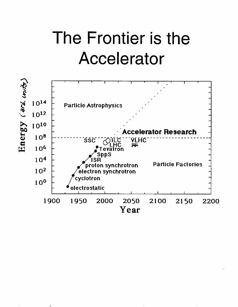
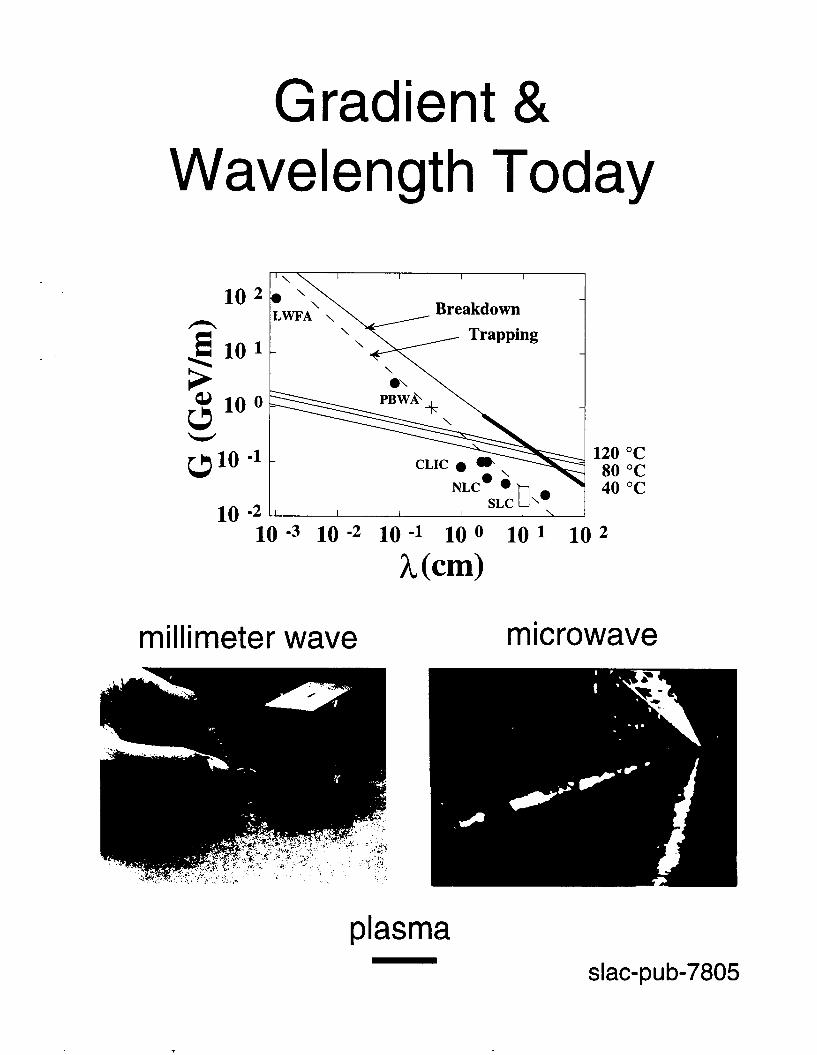
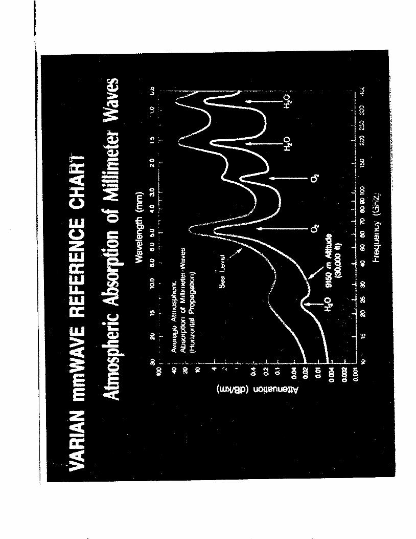
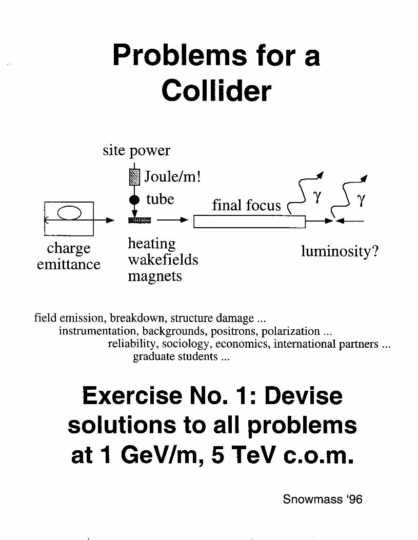
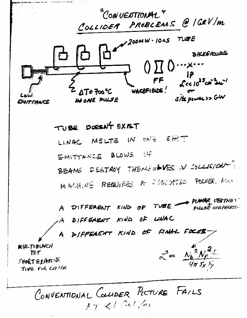
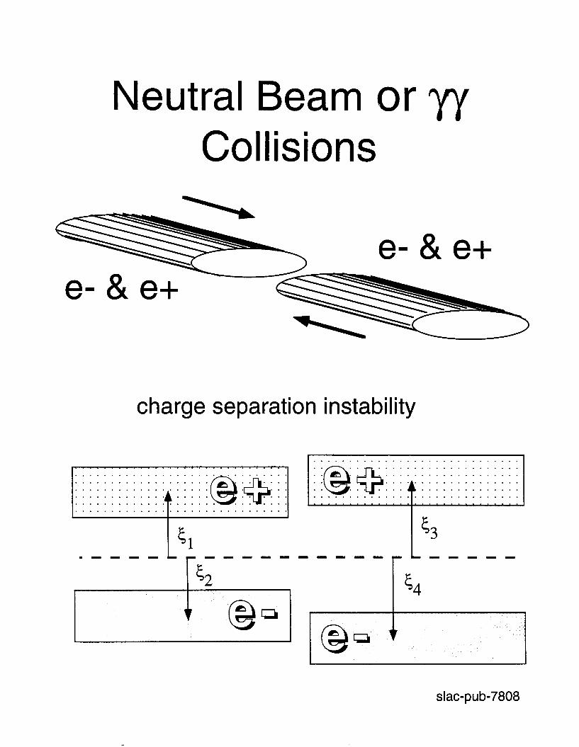
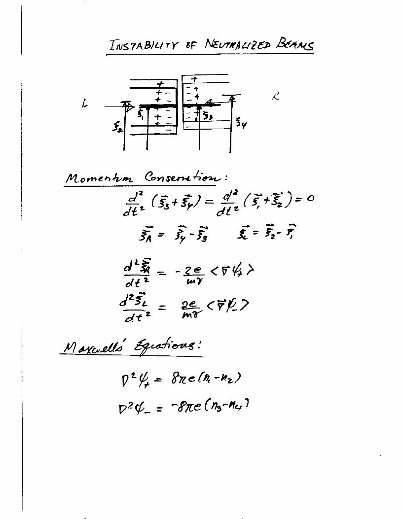
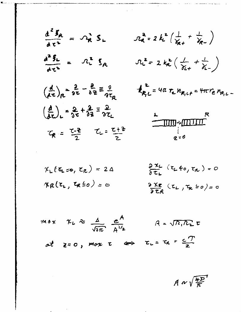
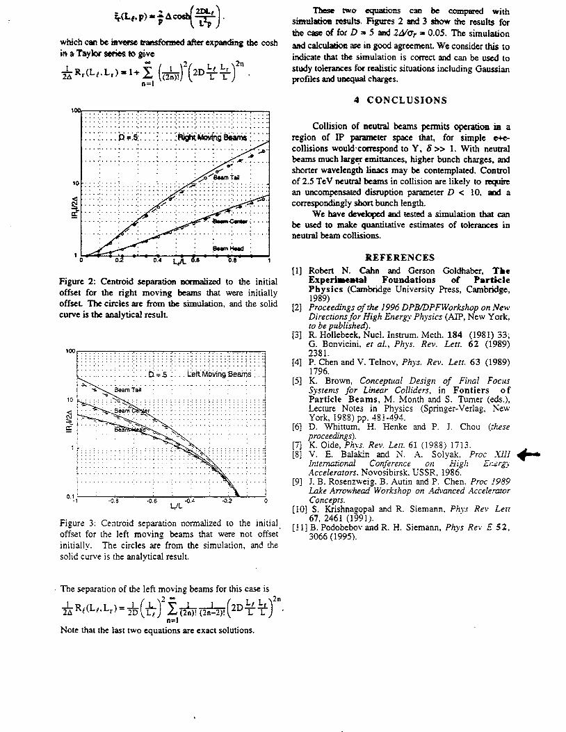
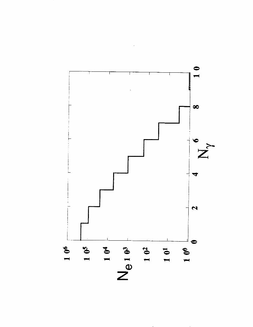
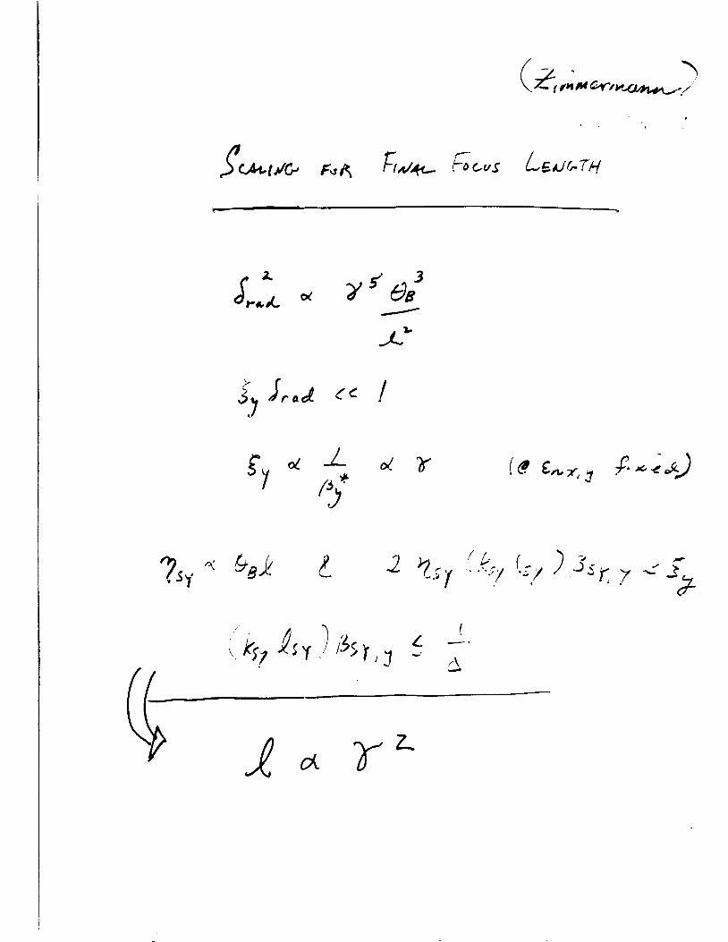
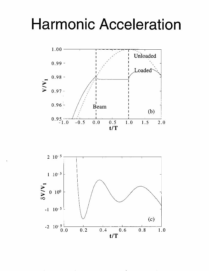
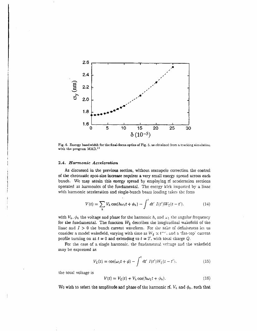
250
200-
- 150 8
250
200
150
I
I lsquo (4
I I
I 8 lsquo - 1
I
- - - - - --- - - - - _ _ I I (d fix I
I I
1
Fig 12 Horizontal and vertical beta functions caculated from he interactioc point bxkwards through the final triplet for an energy deviation relative to the design optiw of (a) -IO (b) -5 and (c] 0 T h e IP beta fiinctions are held constant a 8y z 150 LE
1 a 8 a a a a a I a a 1
I I I I
0 0 m
0 0 N
0 0 T-
O rn
0
I oo I I 0YY -
0 Y R - gt 3 097 - -
1196 -
0 Y S -10 4 5 01) 05 10 15 20
VI
0 Y Y
gt 5
I - - - I
I I
j Unloidrd 1 - I
I I
2 I o - J
I 1 0 - 5 - - $ 0 1 0 0 - v)
I IO -
- 2 01 04 06 0R 10
vr Fig 7 Loaded and unloaded voltage waveforms for a wakefield parameter v = 05 (a) in a conventional single frequency linac with a total rms energy spread of Srms (b) in a two frequency linac with S excluding the first 10 of the beam (shown here is the difference from the average voltage note the magnified scale)
16 x (c) in a three frequency linac with 6 = 25 x
If the initial vertical separation of the electron and positron bunches is Ay the condition for beam combining in the half-chicme is
(21)
The miminum length of the bending magnets is deterinined by the einittauce growth due to synchrotron radiation an effect which was analyzed by Sands12 Crosbie12 and Spence14 and by the induced energy spread In the limit of many photoiis (ea- gtgt 1 with cy z 1137 the fine structure constant) the emittance at the end of the half chicane (for zero initial emittance) is
For = 3 x lo6 this amounts to
(32)
(33)
If we restrict the emittance growth to a value not larger than -er 5 m rad
i
Table 1 IP beam parameters for a W-band h e a r collider The abbreviation neutr stands for neutralization t e charge ComDensation
symbol
E
v
parameter scheme k scheme ZZ cluster collision multiplexing
25 TeV beam energy charge per bunch at ZP particles per bunch number of equal-charge bunches
number of collisions per bunch number of species per bunch
hor bunch separation in linac bunch-bunch time separation longitudinal bunch spacing repetition frequency average beam power (per side) rns bunch length rxns intrabunch energy spread horizontal emittance vertical emittance hor euroP spot size vert IP spot size hor I diver uence vert P divergence hor euroP Seta function vert IP beta function average hac Sera fimction disrup ticn parwieterccllisicn
hewistr parameter wo neutr beanis 30 OF photonselectron
collision wo iieutr beamarrahiung average energy
loss ncllision wo neuer total iuninosiv phch k -A- G Qide eEect Sr w ne1itr
per pulse
(+ir = 2 means neutralization)
e 11- d C L L 1
720 pC 60 pC 45 x io9 375 x 108
a
1 1 or 2
14 mm 300 ps 9 a n
130 Hz 07 MW 30 P a
10-5 100 nm 100 11111 17 Ul
17 Lull 115 prad 1 1 3 mad 150 pm 130 p l u
25 lu 262
200 0S
loo
25
25 a
30 ps 6 m m
22
16 1s
440
Matrix Linac
0
primary 0 0
0 0 0
0
0 0
0
0 OaO 0 0 0 e0 0
0 0 0
0
parallel beamlines
primary transmission line
0 secondary transmission lines I f i c
L t Y Y 0 0 0
t
e - I e -
L 4-- c
3 2 3 M
c13 l A L
I
Circuit Model
primary
e - I e
0 a 0
I n=l n=2 n=3 u v---
~~ VR+- I n v n v3 A
i X
IVI
1 4
1 2
1 0
0 8
0 6
0 4
0 2
0 0 0 0 2 0 4 0 6 0 8 1
t(ns)
1 2
1 0
0 8
0 4
0 2
0 0
1 3
1 2
- E 1 1
1 0 M 8 0 9
0 8
- +
Dispersion attenuation tapering amp beam-loading
0 1 2 4 5 t(ns
1 1 1 1
lsquoI 0 7
0 1 0 2 0 3 0 4 0 5 0 cell number
Cell Design v00
Y
[RQ]=I 44 Ohm Qw=2300
goal is
[RQ]=221 Ohm Qw=2700
Matched Test Section
o 1
Y
I
0
8 b 8 8 9 0 9 2 9 4 9 b
f(GHz)
Wa kef i e I ds
60 pC bunches 15 m pat 10 GeV small aperture miniature magnets
1 0 1
dx 0
L=60 cm Injection at 10 GeV Unit Offset 16 m initial beta scaled inversely with energy
numerical
1 0 0 00 05 10 20 25
z(krnrsquo
t
i
1 09
I 03
xxa 02
1 0
1 00
I I I I 1 I
Ls60 cm Inection at 10 GeV Unit Offset k o 1attice
rC I 1
~
0 5 1 0 15 2 0 2 5 0 0
z(km)
FIG-URG 1 Comparison of the steepest-descents result with simulation for the case of a perfectly aligned linac and an initial beam offset No focusing lattice is present
L=60 cm Injection a1 18 GeV Constant Sinusoid amp Random Offsets No Lattice
-uniform -100 m sinusoid -10 m sinusoid
1 03 random (05m)
i _ - _
- ________
I
0 5 10 1 5 2 0 2 5 1 00 0 0
O m )
FIGURE 2 Results of simulation for a variety of linac structure misalignments uniform offset by x sinusoidal offsets d 100 m and 10 m wavelength with amplitude x and random offsets every 05 m with amplitude x
A Study oE a Planar ampWire Quadwpole Magaet Design
Abstract Thc use of simple cumnt carrying wires embedded in a silicon subsuate laas kcn posed for the puqwsc of quabpole focusing A srmll t t d y has do to show that fyld is quite lierr d that Ibe field sotngth is ampiWt for f- Mug a qeick oprimisation of the wire gcmnw diamp E n c u i y wasfouod~to -1 a d the field padicnt warr found to be 30 Tm using a peak current of 20 A
ReAection and Transmission for First ARDB W-Band Structure 1
09
08
07
5 06 II +
- cu - -- 05
II 04
03
- - nrsquo
0
02
01
I 1 I
06 88 90 92 94 96 98 0 a4
Frequency ( G W
z e u = - c
c
I
c 3 8
Power Source Secondaries
e- I e- e-
1 0 7
1 L=150 cm 1 1 0 6 s
J
1 0 4
1 0 3 1 o 2 0 3 0 4 0 5 0 6 0
slac-pu b-7809
section of a cylindrical diode 480kV 300A
cm- of x75 pasduces 7 H ) A I C d at mode convergeace Q 8 c~rrespoads 80
f 400 hrlf-mgle 1247cm cathode radius 0154 cm mode radius
5iamphr 7 5 dk hput S W requiw4IPW source to keep gain UDamp 98d
lkmampamp rmdb vi WRlO taper and comer reflector ma- cut off to RF
C oll t c t or coasideriag dispersing beam on side-wall with the help of a sbort q d focusing in tbe ve at lOHz l5OJ beam dispersed over 5cm in t
and 4cm in x cmesponds to 4 O W c d
Output power in cxccss for tube U1 VSWRltWeuroE to inhibit oscillation
106
EEV
varian Canada microwave products
MILLIMETER WA VE POWER MODULE
Ihe -82783 series of Miniaturized Millimeter Wave Power
Module u e ideal for airborne urd mobile applications
lhese modules are 8 ComPIct h i h power alternative where
solid UIte souras CIIlllOt provide RF power at high
ampkiency Efficiencies over 10 times that of solid stae can
be achieved with expected life times of 5 - 10 years The
s d l fbotprint power module is under development Please
call Varian for details
PERFORMANCE
ELECTRICAL MECHANICAL
FREQUENCY 0 WEIGHT 7 Ibs PEAK OUTPUT POWER 0 DIMENSIONS- - 3 118 x 3 718 x 9 In- AVERAGE POWER WAVEGUIDE WR 10 (OS0 X I O 0 ins) BANDWIDTH 10 GHz FLANGE UG-387N-modified GAIN COOLING FORCED AIR PRF PULSE WIDTH DUTY PRIME POWER 270 V DC
amp ~ - _ - - - - -
variana
( R E G I S T E R E D I
- I
9 oc
rp
T 0 c
0
H
f
i
z c 0 u
f f 0
E euro
v m d
I
I
f
I
I I I 1 I
i I
I
4 I 1
i I
1 t
I
0 - d k
H n
+
A I
k a
4 u X 0
-I=- d O k 4 0 as
a 0 0
0 0 v-
0 00
0 0 s cu 0 co
_
0 0 d-
I I
0
3
25
2 -
15
1 -
05
0
I 1 1 I
DDS - S f d w z 1 - 0 -
b 0
b 0
(I b 0
b b
b e b
0 b o b - b
b
b b b
b - b
b - b - b
0 - -
- - - e - - - - -
0 -
I I I I 1 I
I
100
50
0 -
-
-
0 i
e 0
e 0
-150 I 6 I I I
-60 -40 -20 0 20 40 60 80 100
beam posiition um
ACCL1560
Mew +via ACCL 1 660
TOR01750
WIRE1950 PROFlO
Proof-of-Principle Experiments
mm-wave structure Dennis Palmer fabrication amp bonding bench measurement
Ping Chou 4 samp
com posi te structures Eddie Lin design bonding of Cu and Diamond
active circuits Sami Tantawi switch test - bench amp high-power
mm-wave source klystrino high-power tube two-beam accelerator
FNW 4 Eric Colbv
structure studies with beam wa kef ie Id i nst ru men t sub-harmonic drive
high-power studies pulsed heating field emission breakdown
Liqun So ig amp Jeff Li c uta) Randy Fowkes amp The Klystron Dept
Marc Hill IHAPGIPPb) amp The NLCTA Mike Seidel 4 PS y
David Pritzkau Lisa Laurent CIKD) Glenn Scheitrum amp The Klystron Dept
Dennis Palmer 1 GeV - I m Test Linac End Station B
harmonic acceleration THz linac plasma acceleration laser linac
amp EFD
(tune in next week)
I
0) c S 0
Q) a
I
E
I
I I (Ib (Ib 4)
4 0 0 I __ c
I
I L= v) f = a o c I + 520
+ Q) 5 I 9 i~ Y
2 - K a 2 b K o h 0 2 0 0 =E zg
CI c 0
CI 0 Q) z
+--- -j
=
CI E s
z
~~~~
-I 0
v) v) Q) 0
2 0
The Reach of High Energy Physics is limited by its instruments
accelerators
Today m245 60-M W klystrons running af 120 Hz fo power a Two-Mile Linac producing 4000 Zrsquos per
Two 2200 m rings being commissioned for a B-Factory
day
Next Week Bring Worked Exercises Exercise No 1 Devise solutions to all problems at 1 GeVm 5 TeV com Exercise No 2 Devise Proof-of-Principle Experiments
Radio convezaation released hy the Chief of Naval Operat ions 40 - 1 - 9amp+
Americans to avoid a collision
Pleaae ampvert your m u s e 15 degrees to the North
Canadians Recommend you divert YOUR course 15 degrees to the South to avoid a collision
Americans This is the Captain of a US Navy ship I say again divert YOUR course
Canadians No f bay again you divert YOUR course
Americans THIS IS TFEE AIRCRAFT CARRIER USS LINCOLN THE SECOND LARGEST SHIP IN THE UNITED STATES ATLANTIC FLEET WE ARE ACCOMPANIED BY THREE DESTROYERS THREE CRUISERS AND NUMEROUS SUPPORT VESSELS I DEMAND THAT YOU CHANGE YOUR COURSE 15 DEGREES NORTH THATS ONE FIVE DEGREES NORTH OR COUNTER-MEASURES WILL BE UNDERTAKEN TO ENSURE THE SAFETY OF THIS SHIP
Canadians This is a lighthouse Your call
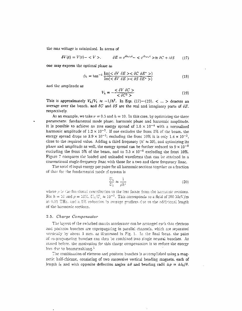
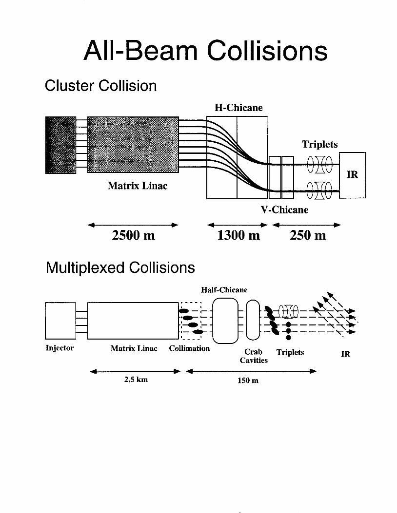
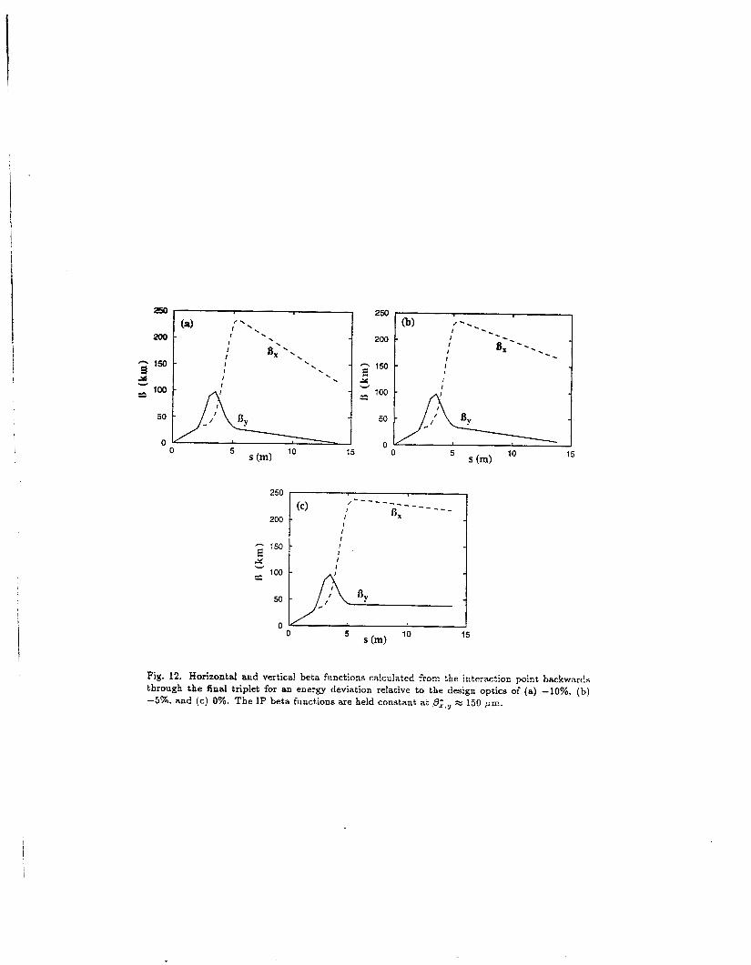
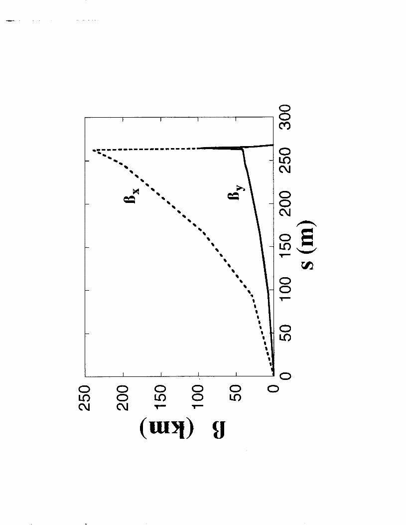
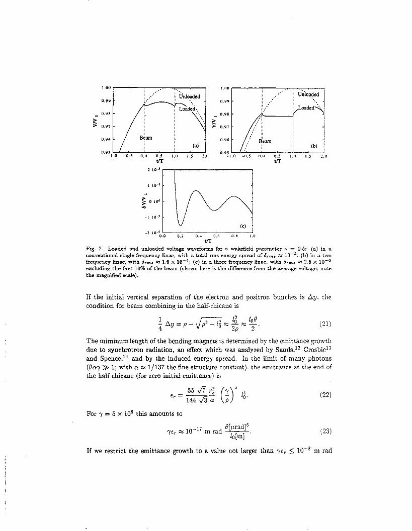
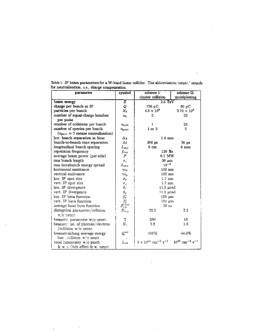
1 2
1 0
0 8
0 4
0 2
0 0
1 3
1 2
- E 1 1
1 0 M 8 0 9
0 8
- +
Dispersion attenuation tapering amp beam-loading
0 1 2 4 5 t(ns
1 1 1 1
lsquoI 0 7
0 1 0 2 0 3 0 4 0 5 0 cell number
Cell Design v00
Y
[RQ]=I 44 Ohm Qw=2300
goal is
[RQ]=221 Ohm Qw=2700
Matched Test Section
o 1
Y
I
0
8 b 8 8 9 0 9 2 9 4 9 b
f(GHz)
Wa kef i e I ds
60 pC bunches 15 m pat 10 GeV small aperture miniature magnets
1 0 1
dx 0
L=60 cm Injection at 10 GeV Unit Offset 16 m initial beta scaled inversely with energy
numerical
1 0 0 00 05 10 20 25
z(krnrsquo
t
i
1 09
I 03
xxa 02
1 0
1 00
I I I I 1 I
Ls60 cm Inection at 10 GeV Unit Offset k o 1attice
rC I 1
~
0 5 1 0 15 2 0 2 5 0 0
z(km)
FIG-URG 1 Comparison of the steepest-descents result with simulation for the case of a perfectly aligned linac and an initial beam offset No focusing lattice is present
L=60 cm Injection a1 18 GeV Constant Sinusoid amp Random Offsets No Lattice
-uniform -100 m sinusoid -10 m sinusoid
1 03 random (05m)
i _ - _
- ________
I
0 5 10 1 5 2 0 2 5 1 00 0 0
O m )
FIGURE 2 Results of simulation for a variety of linac structure misalignments uniform offset by x sinusoidal offsets d 100 m and 10 m wavelength with amplitude x and random offsets every 05 m with amplitude x
A Study oE a Planar ampWire Quadwpole Magaet Design
Abstract Thc use of simple cumnt carrying wires embedded in a silicon subsuate laas kcn posed for the puqwsc of quabpole focusing A srmll t t d y has do to show that fyld is quite lierr d that Ibe field sotngth is ampiWt for f- Mug a qeick oprimisation of the wire gcmnw diamp E n c u i y wasfouod~to -1 a d the field padicnt warr found to be 30 Tm using a peak current of 20 A
ReAection and Transmission for First ARDB W-Band Structure 1
09
08
07
5 06 II +
- cu - -- 05
II 04
03
- - nrsquo
0
02
01
I 1 I
06 88 90 92 94 96 98 0 a4
Frequency ( G W
z e u = - c
c
I
c 3 8
Power Source Secondaries
e- I e- e-
1 0 7
1 L=150 cm 1 1 0 6 s
J
1 0 4
1 0 3 1 o 2 0 3 0 4 0 5 0 6 0
slac-pu b-7809
section of a cylindrical diode 480kV 300A
cm- of x75 pasduces 7 H ) A I C d at mode convergeace Q 8 c~rrespoads 80
f 400 hrlf-mgle 1247cm cathode radius 0154 cm mode radius
5iamphr 7 5 dk hput S W requiw4IPW source to keep gain UDamp 98d
lkmampamp rmdb vi WRlO taper and comer reflector ma- cut off to RF
C oll t c t or coasideriag dispersing beam on side-wall with the help of a sbort q d focusing in tbe ve at lOHz l5OJ beam dispersed over 5cm in t
and 4cm in x cmesponds to 4 O W c d
Output power in cxccss for tube U1 VSWRltWeuroE to inhibit oscillation
106
EEV
varian Canada microwave products
MILLIMETER WA VE POWER MODULE
Ihe -82783 series of Miniaturized Millimeter Wave Power
Module u e ideal for airborne urd mobile applications
lhese modules are 8 ComPIct h i h power alternative where
solid UIte souras CIIlllOt provide RF power at high
ampkiency Efficiencies over 10 times that of solid stae can
be achieved with expected life times of 5 - 10 years The
s d l fbotprint power module is under development Please
call Varian for details
PERFORMANCE
ELECTRICAL MECHANICAL
FREQUENCY 0 WEIGHT 7 Ibs PEAK OUTPUT POWER 0 DIMENSIONS- - 3 118 x 3 718 x 9 In- AVERAGE POWER WAVEGUIDE WR 10 (OS0 X I O 0 ins) BANDWIDTH 10 GHz FLANGE UG-387N-modified GAIN COOLING FORCED AIR PRF PULSE WIDTH DUTY PRIME POWER 270 V DC
amp ~ - _ - - - - -
variana
( R E G I S T E R E D I
- I
9 oc
rp
T 0 c
0
H
f
i
z c 0 u
f f 0
E euro
v m d
I
I
f
I
I I I 1 I
i I
I
4 I 1
i I
1 t
I
0 - d k
H n
+
A I
k a
4 u X 0
-I=- d O k 4 0 as
a 0 0
0 0 v-
0 00
0 0 s cu 0 co
_
0 0 d-
I I
0
3
25
2 -
15
1 -
05
0
I 1 1 I
DDS - S f d w z 1 - 0 -
b 0
b 0
(I b 0
b b
b e b
0 b o b - b
b
b b b
b - b
b - b - b
0 - -
- - - e - - - - -
0 -
I I I I 1 I
I
100
50
0 -
-
-
0 i
e 0
e 0
-150 I 6 I I I
-60 -40 -20 0 20 40 60 80 100
beam posiition um
ACCL1560
Mew +via ACCL 1 660
TOR01750
WIRE1950 PROFlO
Proof-of-Principle Experiments
mm-wave structure Dennis Palmer fabrication amp bonding bench measurement
Ping Chou 4 samp
com posi te structures Eddie Lin design bonding of Cu and Diamond
active circuits Sami Tantawi switch test - bench amp high-power
mm-wave source klystrino high-power tube two-beam accelerator
FNW 4 Eric Colbv
structure studies with beam wa kef ie Id i nst ru men t sub-harmonic drive
high-power studies pulsed heating field emission breakdown
Liqun So ig amp Jeff Li c uta) Randy Fowkes amp The Klystron Dept
Marc Hill IHAPGIPPb) amp The NLCTA Mike Seidel 4 PS y
David Pritzkau Lisa Laurent CIKD) Glenn Scheitrum amp The Klystron Dept
Dennis Palmer 1 GeV - I m Test Linac End Station B
harmonic acceleration THz linac plasma acceleration laser linac
amp EFD
(tune in next week)
I
0) c S 0
Q) a
I
E
I
I I (Ib (Ib 4)
4 0 0 I __ c
I
I L= v) f = a o c I + 520
+ Q) 5 I 9 i~ Y
2 - K a 2 b K o h 0 2 0 0 =E zg
CI c 0
CI 0 Q) z
+--- -j
=
CI E s
z
~~~~
-I 0
v) v) Q) 0
2 0
The Reach of High Energy Physics is limited by its instruments
accelerators
Today m245 60-M W klystrons running af 120 Hz fo power a Two-Mile Linac producing 4000 Zrsquos per
Two 2200 m rings being commissioned for a B-Factory
day
Next Week Bring Worked Exercises Exercise No 1 Devise solutions to all problems at 1 GeVm 5 TeV com Exercise No 2 Devise Proof-of-Principle Experiments
Radio convezaation released hy the Chief of Naval Operat ions 40 - 1 - 9amp+
Americans to avoid a collision
Pleaae ampvert your m u s e 15 degrees to the North
Canadians Recommend you divert YOUR course 15 degrees to the South to avoid a collision
Americans This is the Captain of a US Navy ship I say again divert YOUR course
Canadians No f bay again you divert YOUR course
Americans THIS IS TFEE AIRCRAFT CARRIER USS LINCOLN THE SECOND LARGEST SHIP IN THE UNITED STATES ATLANTIC FLEET WE ARE ACCOMPANIED BY THREE DESTROYERS THREE CRUISERS AND NUMEROUS SUPPORT VESSELS I DEMAND THAT YOU CHANGE YOUR COURSE 15 DEGREES NORTH THATS ONE FIVE DEGREES NORTH OR COUNTER-MEASURES WILL BE UNDERTAKEN TO ENSURE THE SAFETY OF THIS SHIP
Canadians This is a lighthouse Your call
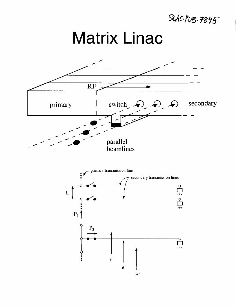
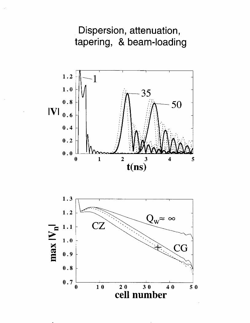
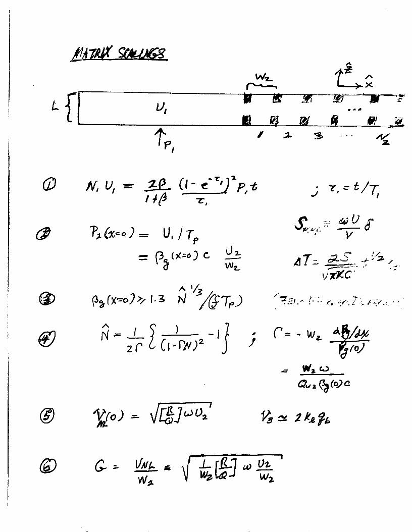
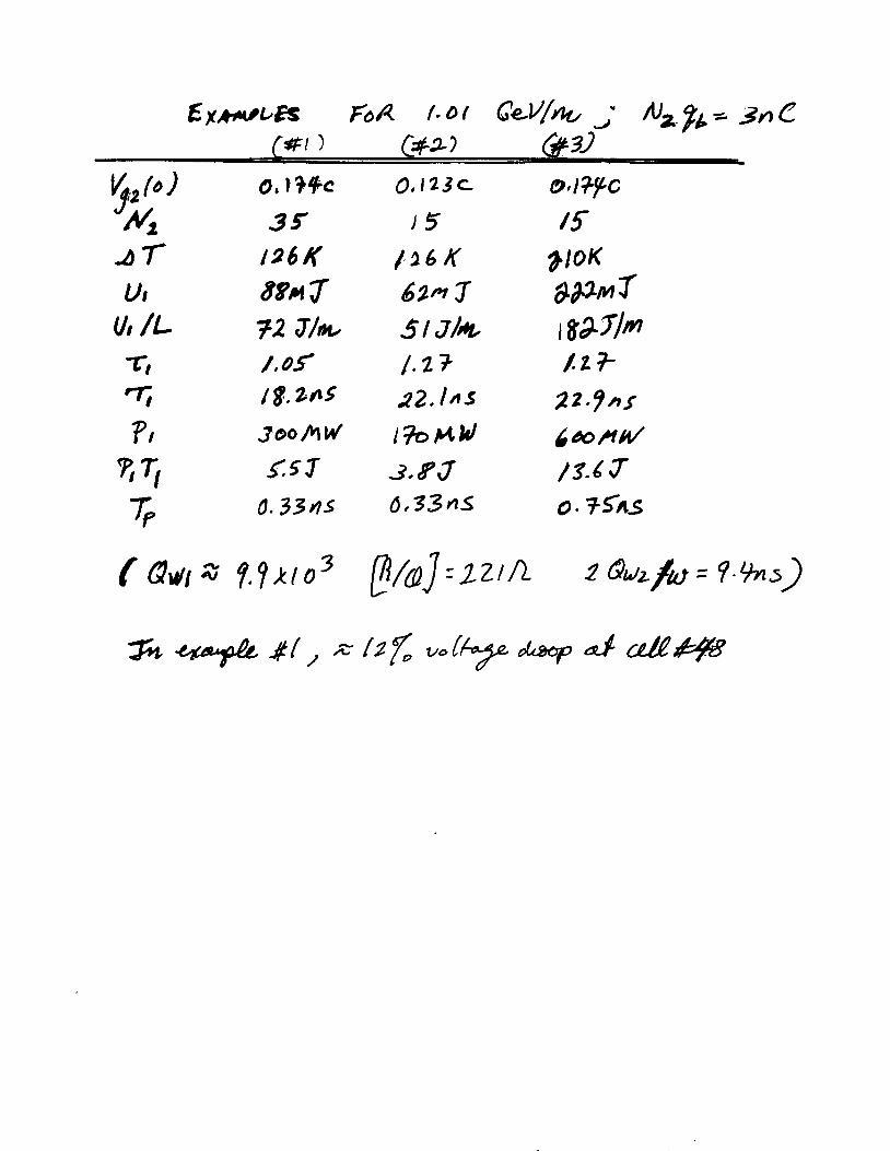
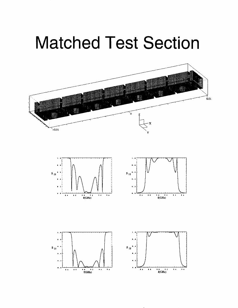
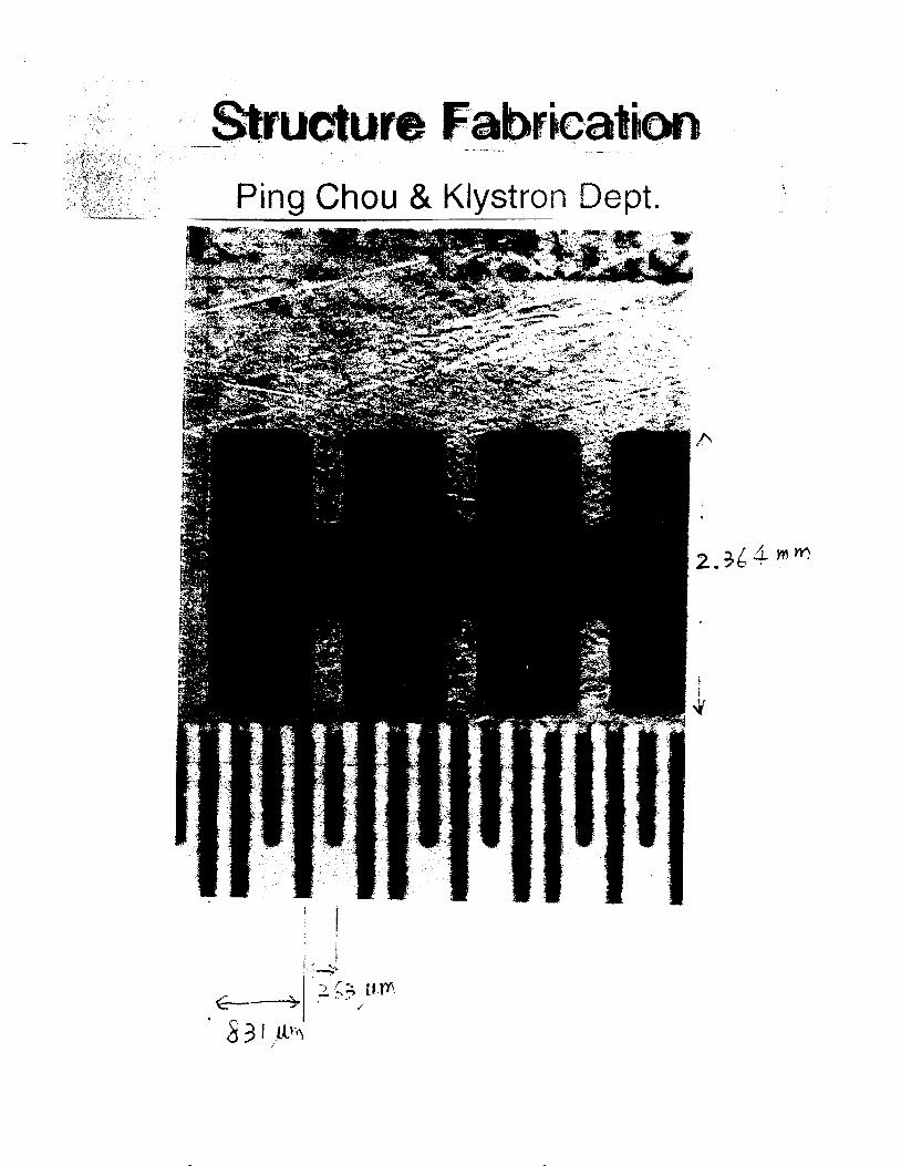
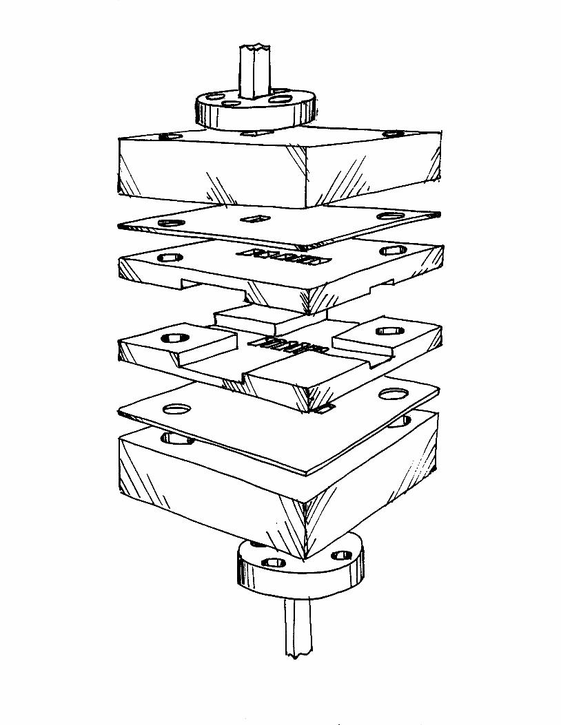
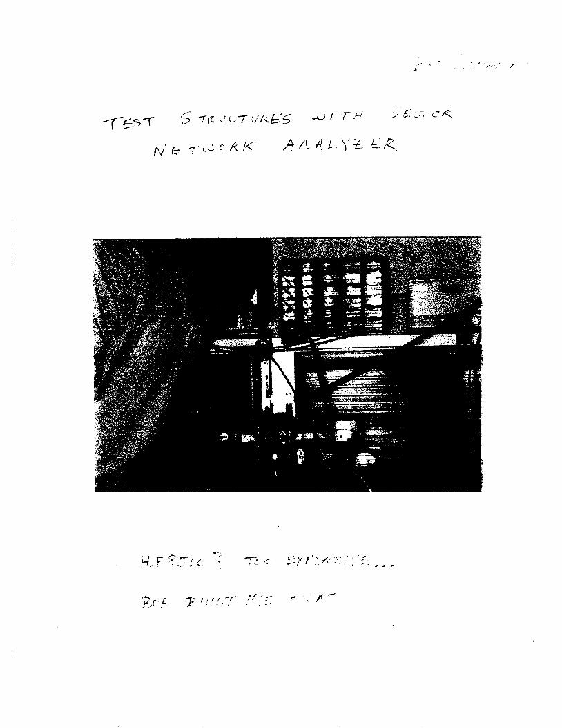
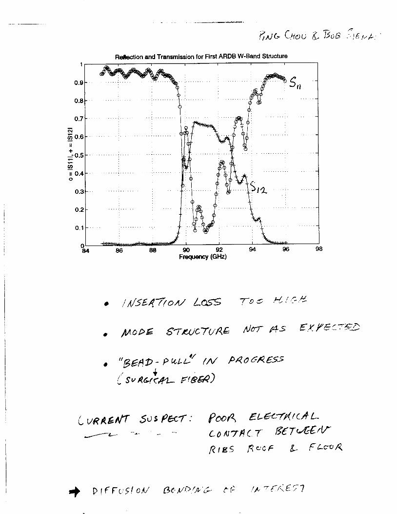
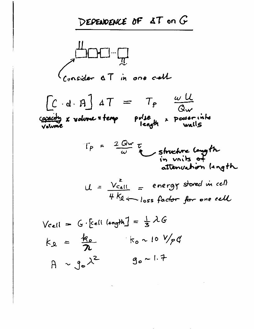
I
I
f
I
I I I 1 I
i I
I
4 I 1
i I
1 t
I
0 - d k
H n
+
A I
k a
4 u X 0
-I=- d O k 4 0 as
a 0 0
0 0 v-
0 00
0 0 s cu 0 co
_
0 0 d-
I I
0
3
25
2 -
15
1 -
05
0
I 1 1 I
DDS - S f d w z 1 - 0 -
b 0
b 0
(I b 0
b b
b e b
0 b o b - b
b
b b b
b - b
b - b - b
0 - -
- - - e - - - - -
0 -
I I I I 1 I
I
100
50
0 -
-
-
0 i
e 0
e 0
-150 I 6 I I I
-60 -40 -20 0 20 40 60 80 100
beam posiition um
ACCL1560
Mew +via ACCL 1 660
TOR01750
WIRE1950 PROFlO
Proof-of-Principle Experiments
mm-wave structure Dennis Palmer fabrication amp bonding bench measurement
Ping Chou 4 samp
com posi te structures Eddie Lin design bonding of Cu and Diamond
active circuits Sami Tantawi switch test - bench amp high-power
mm-wave source klystrino high-power tube two-beam accelerator
FNW 4 Eric Colbv
structure studies with beam wa kef ie Id i nst ru men t sub-harmonic drive
high-power studies pulsed heating field emission breakdown
Liqun So ig amp Jeff Li c uta) Randy Fowkes amp The Klystron Dept
Marc Hill IHAPGIPPb) amp The NLCTA Mike Seidel 4 PS y
David Pritzkau Lisa Laurent CIKD) Glenn Scheitrum amp The Klystron Dept
Dennis Palmer 1 GeV - I m Test Linac End Station B
harmonic acceleration THz linac plasma acceleration laser linac
amp EFD
(tune in next week)
I
0) c S 0
Q) a
I
E
I
I I (Ib (Ib 4)
4 0 0 I __ c
I
I L= v) f = a o c I + 520
+ Q) 5 I 9 i~ Y
2 - K a 2 b K o h 0 2 0 0 =E zg
CI c 0
CI 0 Q) z
+--- -j
=
CI E s
z
~~~~
-I 0
v) v) Q) 0
2 0
The Reach of High Energy Physics is limited by its instruments
accelerators
Today m245 60-M W klystrons running af 120 Hz fo power a Two-Mile Linac producing 4000 Zrsquos per
Two 2200 m rings being commissioned for a B-Factory
day
Next Week Bring Worked Exercises Exercise No 1 Devise solutions to all problems at 1 GeVm 5 TeV com Exercise No 2 Devise Proof-of-Principle Experiments
Radio convezaation released hy the Chief of Naval Operat ions 40 - 1 - 9amp+
Americans to avoid a collision
Pleaae ampvert your m u s e 15 degrees to the North
Canadians Recommend you divert YOUR course 15 degrees to the South to avoid a collision
Americans This is the Captain of a US Navy ship I say again divert YOUR course
Canadians No f bay again you divert YOUR course
Americans THIS IS TFEE AIRCRAFT CARRIER USS LINCOLN THE SECOND LARGEST SHIP IN THE UNITED STATES ATLANTIC FLEET WE ARE ACCOMPANIED BY THREE DESTROYERS THREE CRUISERS AND NUMEROUS SUPPORT VESSELS I DEMAND THAT YOU CHANGE YOUR COURSE 15 DEGREES NORTH THATS ONE FIVE DEGREES NORTH OR COUNTER-MEASURES WILL BE UNDERTAKEN TO ENSURE THE SAFETY OF THIS SHIP
Canadians This is a lighthouse Your call
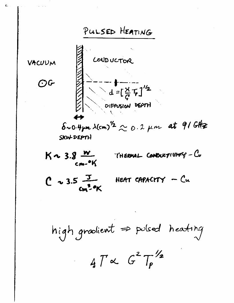
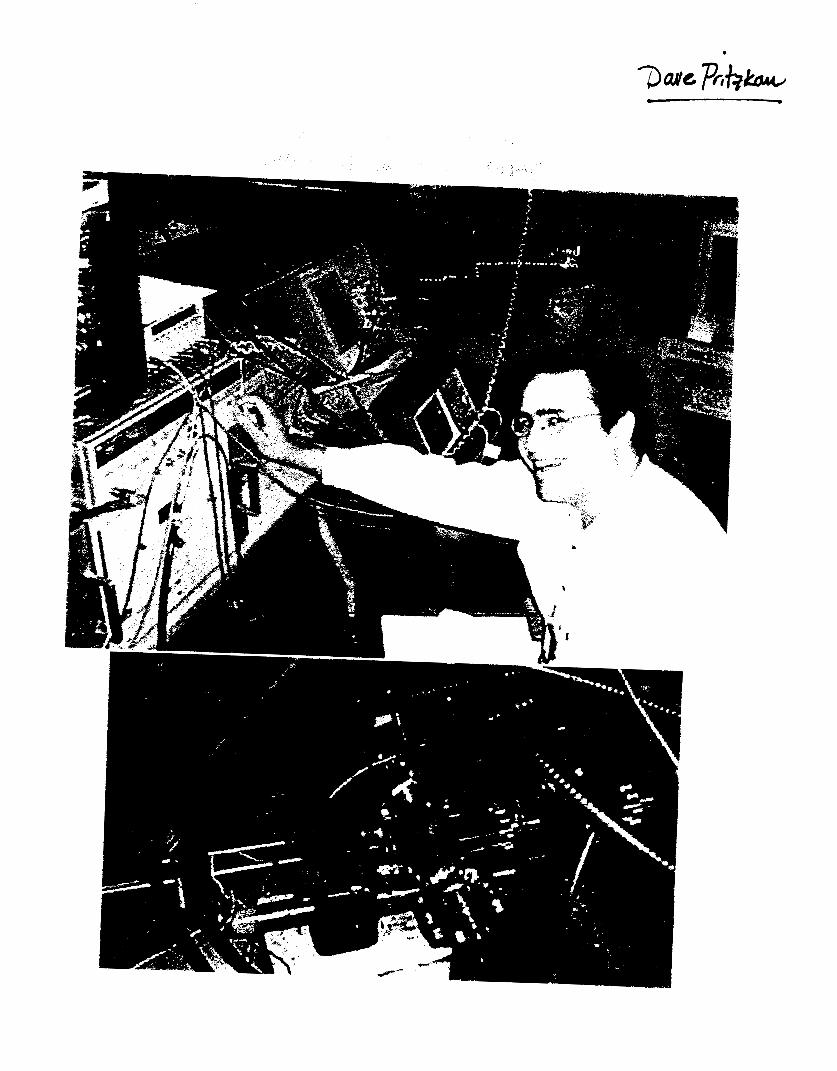
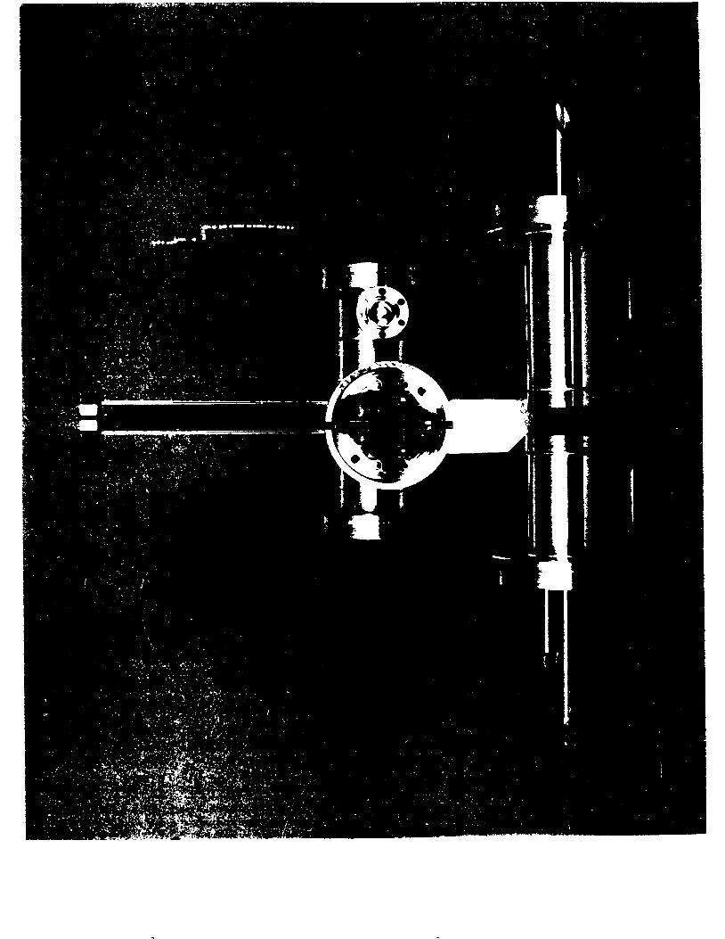
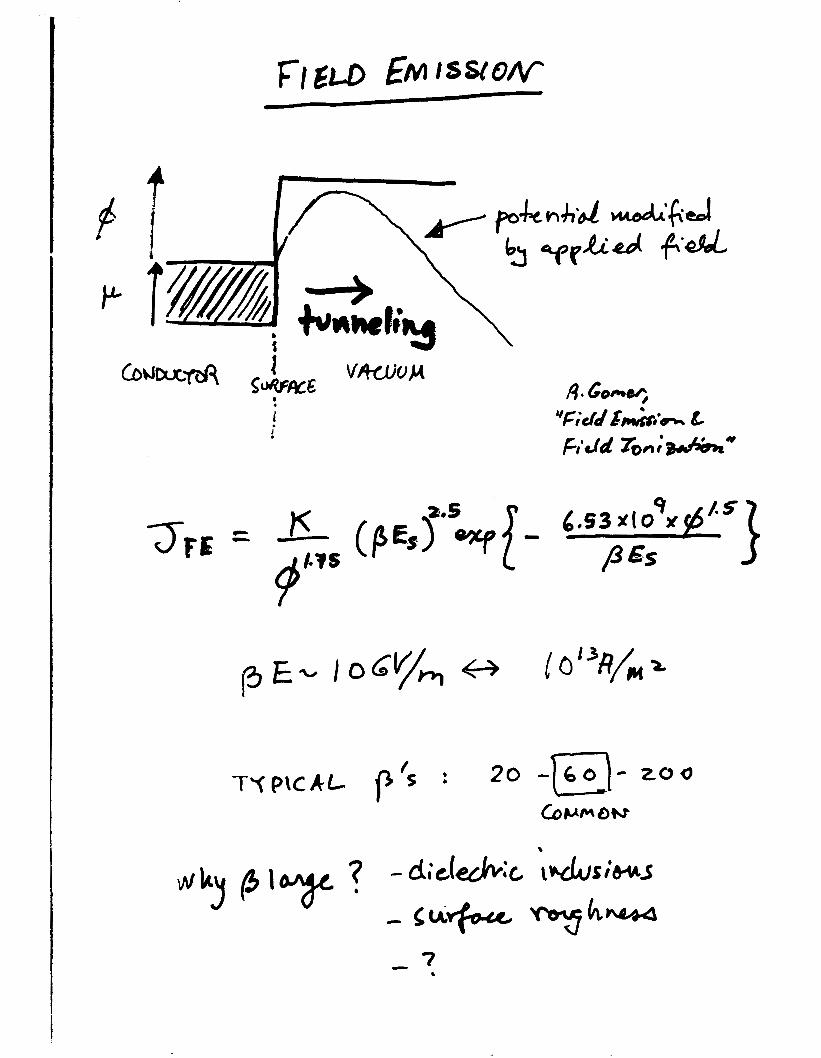
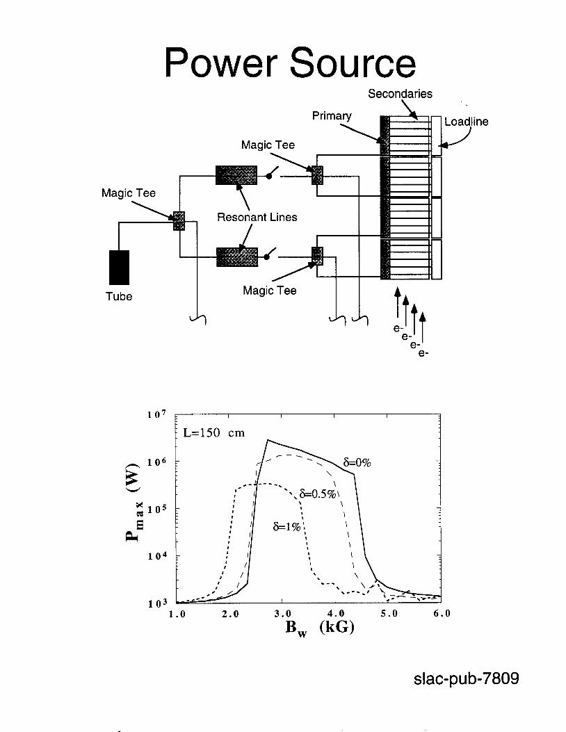
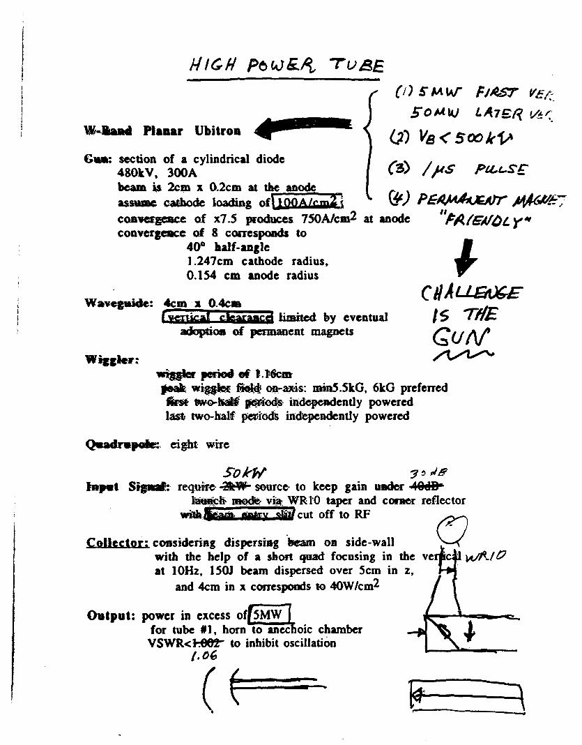
I
0) c S 0
Q) a
I
E
I
I I (Ib (Ib 4)
4 0 0 I __ c
I
I L= v) f = a o c I + 520
+ Q) 5 I 9 i~ Y
2 - K a 2 b K o h 0 2 0 0 =E zg
CI c 0
CI 0 Q) z
+--- -j
=
CI E s
z
~~~~
-I 0
v) v) Q) 0
2 0
The Reach of High Energy Physics is limited by its instruments
accelerators
Today m245 60-M W klystrons running af 120 Hz fo power a Two-Mile Linac producing 4000 Zrsquos per
Two 2200 m rings being commissioned for a B-Factory
day
Next Week Bring Worked Exercises Exercise No 1 Devise solutions to all problems at 1 GeVm 5 TeV com Exercise No 2 Devise Proof-of-Principle Experiments
Radio convezaation released hy the Chief of Naval Operat ions 40 - 1 - 9amp+
Americans to avoid a collision
Pleaae ampvert your m u s e 15 degrees to the North
Canadians Recommend you divert YOUR course 15 degrees to the South to avoid a collision
Americans This is the Captain of a US Navy ship I say again divert YOUR course
Canadians No f bay again you divert YOUR course
Americans THIS IS TFEE AIRCRAFT CARRIER USS LINCOLN THE SECOND LARGEST SHIP IN THE UNITED STATES ATLANTIC FLEET WE ARE ACCOMPANIED BY THREE DESTROYERS THREE CRUISERS AND NUMEROUS SUPPORT VESSELS I DEMAND THAT YOU CHANGE YOUR COURSE 15 DEGREES NORTH THATS ONE FIVE DEGREES NORTH OR COUNTER-MEASURES WILL BE UNDERTAKEN TO ENSURE THE SAFETY OF THIS SHIP
Canadians This is a lighthouse Your call
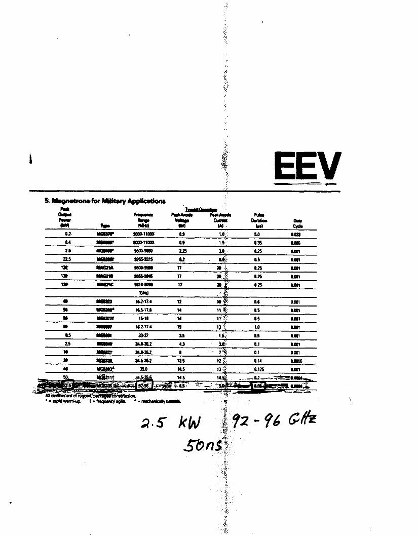
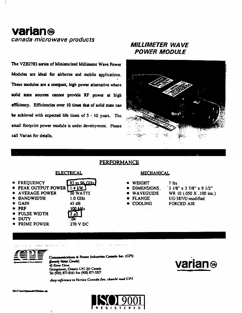