advanced air pipe system - transair aluminum pipe air pipe system ... material transairtechnology...
TRANSCRIPT
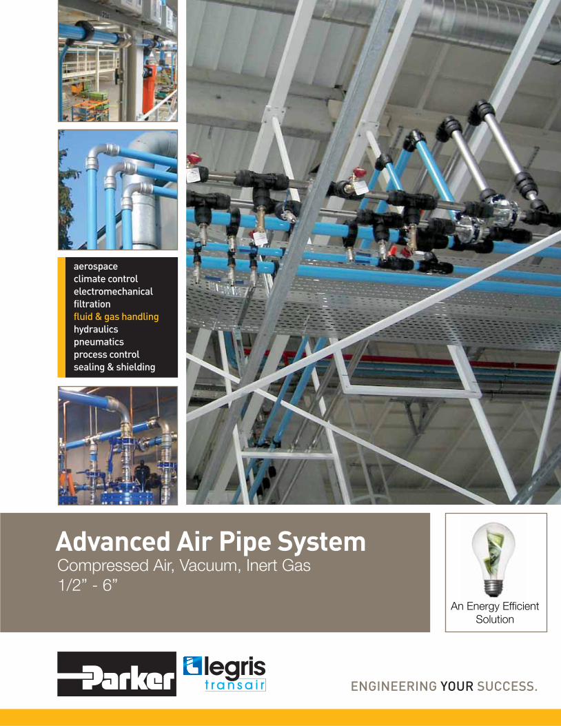
Advanced Air Pipe SystemCompressed Air, Vacuum, Inert Gas
1/2” - 6”An Energy Effi cient
Solution

TransairInnovative TechnologyTransair’s aluminum compressed air pipe system is quick to install and easy to modify. Transair components are removable and interchangeable, which allows immediate and easy layout modi� ca-tions. Unlike the performance of steel and copper, which degrades over time due to corrosion, Transair provides clean air quality with optimum � ow rate performance.
Transair also offers signi� cant savings on installation, maintenance and operating costs compared to traditional pipe. The quick, instant connections eliminate the need to thread or solder pipe. Labor accounts for only 20% of the cost of installing Transair, while labor accounts for 50% to 80% of the cost of installing steel or copper systems. Transair’s aluminum pipe system signi� cantly reduces plant energy costs by increasing ef� ciency, reducing pressure drops, and eliminating leaks.
Available in ½” to 6” pipe sizes, the Parker Transair system features quick connect technology that secures connections with a simple push and provides a leak-free guarantee. The aluminum pipe eliminates corrosion, ensuring the longevity of equipment and helps to avoid frequent changes of � ltration elements. Transair can also be integrated into existing copper and steel piping without compromising performance, making it perfect for upgrades or expansion projects.
Transair‘s additional bene� ts include:• Energy ef� cient • Lower install costs• Quick connect technology • Immediate pressurization• Removable and reusable • Modular design• No corrosion • Leak-free guarantee• Full bore design • 1/2“ - 6“ pipe sizes
! WARNINGFAILURE, IMPROPER SELECTION OR IMPROPER USE OF THE PRODUCTS AND/OR SYSTEMS DESCRIBED HEREIN OR RELATED ITEMS CAN CAUSE DEATH, PERSONAL INJURY AND PROPERTY DAMAGE.
This document and other information from Parker Hanni� n Corporation, its subsidiaries and authorized distributors provide product and/or system options for further investigation by users having technical expertise. The user, through its own analysis and testing, is solely responsible for making the � nal selection of the system and components and assuring that all performance, endurance, maintenance, safety and warning requirements of the application are met. The user must analyze all aspects of the application, follow applicable industry standards, and follow the information concerning the product in the current product catalog and in any other materials provided from Parker or its subsidiaries or authorized distributors. To the extent that Parker or its subsidiaries or authorized distributors provide component or system options based upon data or speci� cations provided by the user, the user is responsible for determining that such data and speci� cations are suitable and suf� cient for all applications and reasonably foreseeable uses of the components or systems.
>
>
>
>
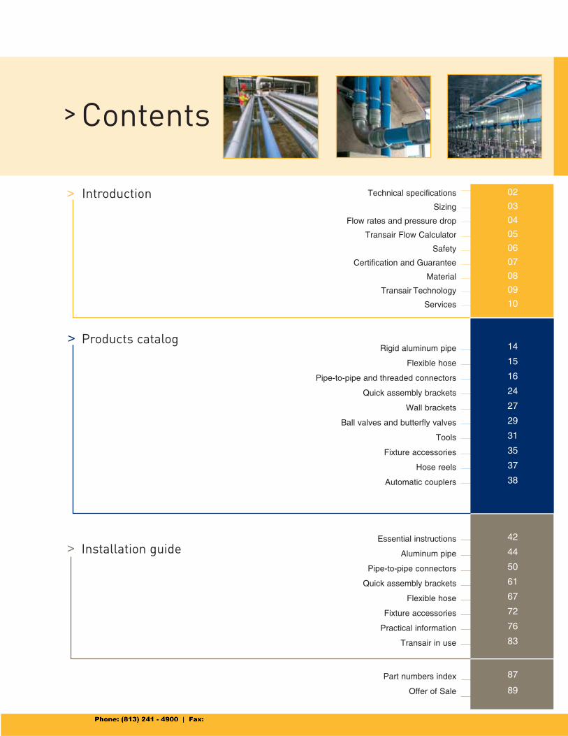
Introduction
Contents
Technical specifications
Sizing
Flow rates and pressure drop
Transair Flow Calculator
Safety
Certification and Guarantee
Material
Transair Technology
Services
Rigid aluminum pipe
Flexible hose
Pipe-to-pipe and threaded connectors
Quick assembly brackets
Wall brackets
Ball valves and butterfly valves
Tools
Fixture accessories
Hose reels
Automatic couplers
Essential instructions
Aluminum pipe
Pipe-to-pipe connectors
Quick assembly brackets
Flexible hose
Fixture accessories
Practical information
Transair in use
Part numbers index
Offer of Sale
Products catalog
Installation guide
02
03
04
05
06
07
08
09
10
14
15
16
24
27
29
31
35
37
38
42
44
50
61
67
72
76
83
87
89
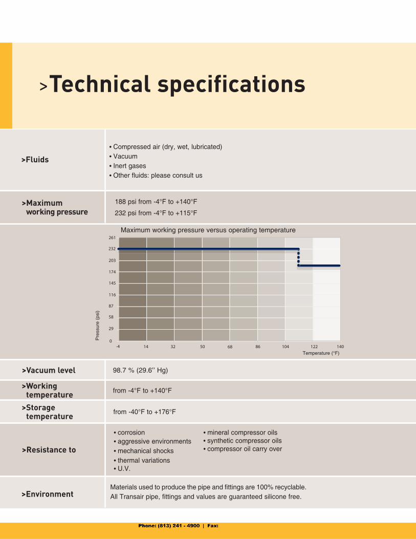
>Technical specifications
> Maximum working pressure
>Fluids
• Compressed air (dry, wet, lubricated)• Vacuum• Inert gases • Other fluids: please consult us
188 psi from -4°F to +140°F
232 psi from -4°F to +115°F
98.7 % (29.6’’ Hg)>Vacuum level
from -4°F to +140°F> Working
temperature
from -40°F to +176°F> Storage temperature
Maximum working pressure versus operating temperature
Pre
ssur
e (p
si)
Temperature (°F)
>Resistance to
• corrosion • mineral compressor oils • aggressive environments • synthetic compressor oils
• mechanical shocks • compressor oil carry over
• thermal variations • U.V.
> EnvironmentMaterials used to produce the pipe and fittings are 100% recyclable.All Transair pipe, fittings and values are guaranteed silicone free.
2/3
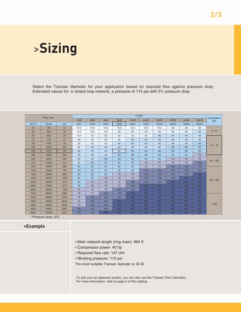
164ft 328ft 492ft 984ft 1640ft 2460ft 3280ft 4265ft 5249ft 6561ft
Nm3/h Nl/min cfm 50m 100m 150m 300m 500m 750m 1000m 1300m 1600m 2000m
10 167 6 16.5 16.5 16.5 16.5 16.5 16.5 16.5 25 25 252 - 1030 500 18 16.5 16.5 16.5 25 25 25 25 25 25 40
50 833 29 16.5 25 25 25 25 25 40 40 40 40
10 - 40
70 1167 41 25 25 25 25 40 40 40 40 40 40
100 1667 59 25 25 25 40 40 40 40 40 40 63
150 2500 88 25 40 40 40 40 40 40 63 63 63
250 4167 147 40 40 40 40 63 63 63 63 63 63
350 5833 206 40 40 40 63 63 63 63 63 63 76
40 - 100500 8333 294 40 40 63 63 63 63 63 76 76 76
750 12500 441 40 63 63 63 63 76 76 76 76 100
1000 16667 589 63 63 63 63 63 76 76 100 100 100
100 - 425
1250 20833 736 63 63 63 63 63 100 100 100 100 100
1500 25000 883 63 63 63 76 76 100 100 100 100 100*
1750 29167 1030 63 63 76 76 76 100 100 100 100* 100*
2000 33333 1177 63 76 76 76 100 100 100 100* 100* 100*
2500 41667 1471 63 76 76 76 100 100* 100* 100* 100* 100*
3000 50000 1766 76 76 76 100 100 100* 100* 100* 100* 100*
3500 58333 2060 76 76 100 100 100* 100* 100* 100* 100* 100*
> 425
4000 66667 2354 76 100 100 100 100* 100* 100* 100* 100* 100*
4500 75000 2649 76 100 100 100* 100* 100* 100* 100* 100* 100*
5000 83333 2943 76 100 100 100* 100* 100* 100* 100* 100* 100*
5500 91667 3237 100 100 100 100* 100* 100* 100* 100* 100* 100*
6000 100000 3531 100 100 100* 100* 100* 100* 100* 100* 100* 100*
>Sizing
Select the Transair diameter for your application based on required flow against pressure drop. Estimated values for: a closed loop network, a pressure of 115 psi with 5% pressure drop.
> Example
• Main network length (ring main): 984 ft• Compressor power: 40 hp • Required flow rate: 147 cfm• Working pressure: 115 psiThe most suitable Transair diameter is: Ø 40.
To size your air pipework system, you can also use the Transair Flow Calculator. For more information, refer to page 5 of this catalog.
*Pressure drop >5%
Flow rateLength
Compressor (hp)

>Flow rates and pressure drop
Measurements provided by the official French testing body CETIM - Centre Technique des Industries Mecaniques. Charts are based on a 100 feet straight Transair line.
Flo
w r
ate
(Nm
3/h)
Pressure (psi)
Flo
w r
ate
(Nm
3/h)
Pressure (psi)
Maximum flow rate with 1.45 psi pressure drop. (To convert to cfm, use a coefficient of 0.588.)
Maximum flow rate with 5% pressure drop (To convert to cfm, use a coefficient of 0.588.)

4/5
> DownloadThe new Transair Flow Calculator from our web site: www.parkertransair.com
The Transair Flow Calculator helps you to choose the most suitable diameter for your installation. Enter the flow of your compressor, the system pressure rating and the total equivalent length of the system. Select ring main or straight line layout, enter your preferred unit of calculation and then click for an immediate indication of the most suitable Transair
diameter (with a pressure drop of less than 5%).
>Transair Flow Calculator
> Example> Flow rate: 850 cfm at 109 psi > Ring main: 1788 feet> The recommended Transair diameter is Ø 100mm (pressure drop of 145 psi = less than 5 %)

>Safety
All Transair components are non-flammable with no propagation of flame.• pipe-to-pipe and male connectors, ball valves and butterfly valves: conform to UL94HB standard• fixture clips: conform to UL94V-2 standard• flexible hoses: conform to ISO 8030 norm for compressed air applications and to EN 12115 norm for vacuum applications• pipe powder coat finish classified M0
>Fire resistance
In areas of potential risk, the earthing and electrical continuity of metallic components are obligatory. The Transair system can be used in such environments by undertaking the appropriate precautions. For more information, please consult us.
>Electrical conductivity
>CE conformity Transair conforms to European standard 97/23 CEE - §3.3 (equipment under pressure).
DECLARATION OF CE CONFORMITY
Supplied in conformity with the
DIRECTIVE on EQUIPMENT UNDER PRESSURE
97/23/CEE
We hereby declare that all Transair connectors manufactured by Parker should be considered as piping
components which designed according to sound working practice. “Piping includes in particular a pipe or
system of pipes, tubing, fi ttings, expansion joints, hoses, or other pressure-bearing components as appro-
priate” – cf acceptance by the «pressure working group» dated 28/01/1999 and by the GTP Commission
dated 27/11/1998.
Products designed according to the code of practice.
Product description: Transair connectors Ø 16.5 - Ø 25 - Ø 40 - Ø 63 - Ø 76 - Ø 100
Applicable approvals: AFAQ Certifi cate of Approval, EN ISO 9001

6/7
>Certification and Guarantee
Legris S.A. is certified ISO 9001 version 2000 and ope-rates a Quality Management System in order to ensure the level of quality and ser-vice that is expected by its customers.
>Certification ISO 9001 version 2000
A product certified TÜV is a pledge of safety and quality. The Group TÜV thus certifies independent test results – in particular, the properties of the pro-ducts and the standards whereby they were exa-mined.
>TÜV certification
QUALICOAT certification is a guarantee of the qua-lity of the lacquer finish applied to Transair alumi-num pipe.
>QUALICOAT certification
Transair meets the require-ment of ASME B31.1 and B31.3. - which stipulates “the minimum require-ments for the design, materials, fabrication, erection, test and inspection of power and auxiliary piping systems for industrial insti-tutional plants”.
>ASME B31.1>ASME B31.3
All Transair components are guaranteed for 10 years.
- TRANSAIR GUARANTEE -
Parker-Hannifi n Corporation warrants its Transair products to be free of defects in material and workmanship for a period
of ten (10) years from the date of purchase of the products. Parker-Hannifi n Corporation makes no other warranties,
express or implied. This limitation explicitly excludes any implied warranty of merchantability or fi tness for a particular
purpose. The sole remedy for breach of this warranty of material and workmanship or for negligence in manufacture or
design is limited to replacement or repair, at the sole option of Parker-Hannifi n Corporation, of any defective parts which
are returned to Parker-Hannifi n Corporation (prepaid) within ten (10) years of original purchase. In no event shall Parker-
Hannifi n Corporation be liable for indirect, special, incidental or consequential damages of any kind. No allowance will
be made for repairs made by the purchaser.
THIS WARRANTY IS EXPRESSLY IN LIEU OF ANY AND ALL OTHER WARRANTIES AND REPRESENTATIONS,
EXPRESS OR IMPLIED, INCLUDING BUT NOT LIMITED TO, THE WARRANTY OF FITNESS FOR A PARTICULAR
PURPOSE AND THE WARRANTY OF MERCHANTABILITY. PARKER-HANNIFIN CORPORATIONMAKES NO WAR-
RANTY THAT THE GOODS SOLD HEREUNDER ARE DELIVERED FREE OF THE RIGHTFUL CLAIM OF ANY THIRD
PARTY BY WAY OF INFRINGEMENT OR OTHERWISE. THERE ARE NO WARRANTIES THAT EXTEND BEYOND
THE DESCRIPTION ON THE FACE HEREOF. THE EXCLUSIVE REMEDY FOR DEFECTIVE PRODUCTS SHALL BE
ONLY AS STATED HEREIN.
Parker-Hannifi n Corporation does not warrant the design, assembly or installation of the system, but only the Transair
components as stated herein. Parker-Hannifi n Corporation is not responsible for improper design, assembly or instal-
lation, or for any modifi cations of the Transair products. The warranty herein is void upon (a) failure to follow any of the
assembly or installation guidelines, (b) installation, repair or relocation of the components by a person other than a trai-
ned and qualifi ed installer; (c) alteration, misuse or abuse of, or damage to, any of the Transair products, (d) operation
beyond the design range, excessive pressure of stress, or mishandling in any way, (e) use other than for the intended
purpose or in a manner other than as specifi ed by Parker-Hannifi n Corporation, or (f) improper assembly, installation,
service or maintenance. This Limited Warranty, and Parker-Hannifi n Corporation’s responsibility, may be further limited,
but may not be expanded, by Parker-Hannifi n Corporation’s terms and conditions of sale, as set forth on the reverse side
of the Parker-Hannifi n Corporation invoice.
Ø 16.5 - Ø 25 - Ø 40 Ø 63 Ø 76 - Ø 1001013A TA16
1016A TA16
EW05
FP01
4002 RP01
4088 - 4099 RR01
Anti whip-lash strapSteel
6602 - 6604 RR61
6605 RX02
6606 RX12
6612 RX04
6621 RX20
6625 RX24
6651 RX64
6663 RX66
6662 RX30
6666 VR02
6676 VR03
6684
6688
EA98
RA68 - RA69
RA65
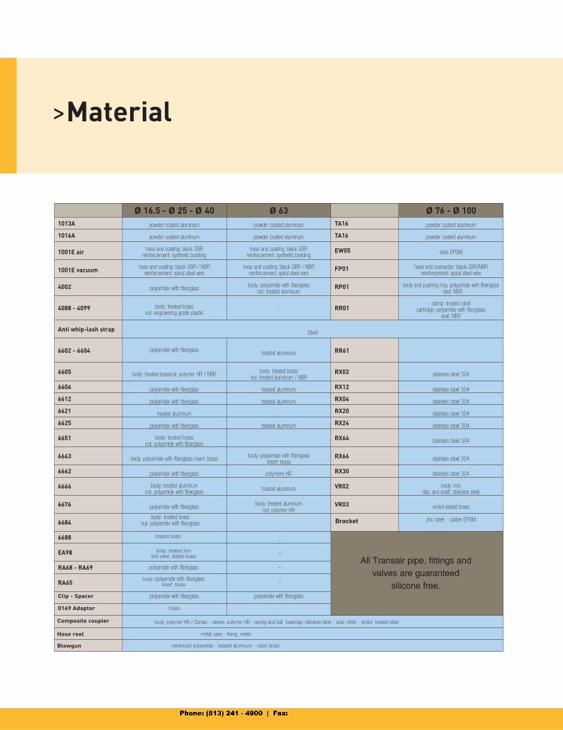
>Material
powder coated aluminum powder coated aluminum powder coated aluminum
powder coated aluminum powder coated aluminum powder coated aluminum
1001E air hose and coating: black SBRreinforcement: synthetic braiding
hose and coating: black SBRreinforcement: synthetic braiding
seal: EPDM
1001E vacuum hose and coating: black SBR / NBRreinforcement: spiral steel wire
hose and coating: black SBR / NBRreinforcement: spiral steel wire
hose and connector: black SBR/NBRreinforcement: spiral steel wire
polyamide with fiberglassbody: polyamide with fiberglass
nut: treated aluminumbody and pushing ring: polyamide with fiberglass
- seal: NBR
body: treated brassnut: engineering grade plastic
-clamp: treated steel
cartridge: polyamide with fiberglassseal: NBR
polyamide with fiberglasstreated aluminum
body: treated brassnut: polymer HR / NBRbody: treated brass
nut: treated aluminum / NBRstainless steel 304
polyamide with fiberglass treated aluminum stainless steel 304
polyamide with fiberglass treated aluminum stainless steel 304
treated aluminum - stainless steel 304
polyamide with fiberglass treated aluminum stainless steel 304
body: treated brassnut: polyamide with fiberglass
- stainless steel 304
body: polyamide with fiberglass insert: brassbody: polyamide with fiberglass
insert: brassstainless steel 304
polyamide with fiberglass polymère HR stainless steel 304
body: treated aluminumnut: polyamide with fiberglass
treated aluminumbody: iron
disc and shaft: stainless steel
polyamide with fiberglassbody: treated aluminum
nut: polymer HRnickel-plated brass
-
All Transair pipe, fittings and valves are guaranteed
silicone free.
-
body: treated ironball valve: plated brass
-
polyamide with fiberglass -
body: polyamide with fiberglassinsert: brass
-
Composite coupler
body: treated brassnut: polyamide with fiberglass
zinc steel - rubber EPDMBracket
Clip - Spacer polyamide with fiberglass polyamide with fiberglass
0169 Adaptor brass -
body: polymer HR / Zamac - sleeve: polymer HR - spring and ball bearings: stainless steel - seal: nitrile - probe: treated steel
treated brass
Hose reel metal case - fixing: metal
Blowgun reinforced polyamide - treated aluminum - insert brass
8/9
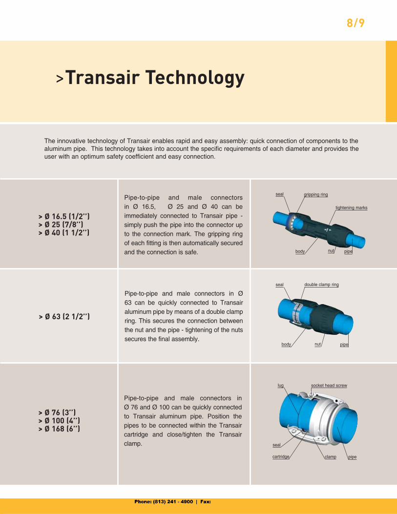
> Ø 16.5 (1/2’’)> Ø 25 (7/8’’)> Ø 40 (1 1/2’’)
> Ø 63 (2 1/2’’)
> Ø 76 (3’’)> Ø 100 (4’’)> Ø 168 (6’’)
>Transair Technology
The innovative technology of Transair enables rapid and easy assembly: quick connection of components to the aluminum pipe. This technology takes into account the specific requirements of each diameter and provides the user with an optimum safety coefficient and easy connection.
Pipe-to-pipe and male connectors in Ø 16.5, Ø 25 and Ø 40 can be immediately connected to Transair pipe - simply push the pipe into the connector up to the connection mark. The gripping ring of each fitting is then automatically secured and the connection is safe.
Pipe-to-pipe and male connectors in Ø 63 can be quickly connected to Transair aluminum pipe by means of a double clamp ring. This secures the connection between the nut and the pipe - tightening of the nuts secures the final assembly.
Pipe-to-pipe and male connectors in Ø 76 and Ø 100 can be quickly connected to Transair aluminum pipe. Position the pipes to be connected within the Transair cartridge and close/tighten the Transair clamp.
cartridge clamp pipe
lug socket head screw
seal
gripping ringseal
tightening marks
body nut pipe
body nut pipe
seal double clamp ring

>Services
A number of additional Transair services help you throughout your projects.
> Project assistance
Understanding, Proximity, Responsiveness.Transair technical teams are at your disposal to study and help design your air system. In particular, they assist you in your project with:
• Information on the Transair products and services• Guidance and training on how to assemble the system• Advice on “best practice” in order to reduce your consumption of energy• Ongoing assistance and follow-up• On-site advisory presence at construction and installation locations
Our customer service teams will coordinate a quick response to your requirements.
> Customer service • Product availability
• Order processing and follow-up
• Delivery time-phasing and modification
• Technical information
> Costing service• Advice• Design software
Contact Parker Legris Transair
> Wherever you are in the world, you can contact us:• by phone• by fax• by mail• by e-mail
7205 E. Hampton Ave.Mesa, AZ 85209Ph. (480) 830-7764 Fax (480) 325-3571www.parkertransair.com

ØGL
Z
ØD
Z
TransairSignifi cant Energy SavingsCompressed air represents one of the largest opportunities for immediate energy savings. Plant management is often surprised to hear that compressed air can represent 20-50% of a plant’s electric bill. Plant management is truly amazed when they fi nd out that using an effi cient piping system specifi cally designed for compressed air can reduce their energy bill by 30-60%, many times within a24-month period.
For instance, a large industrial plant recently redesigned their compressed air system with Transair. This accounted for 35% savings in the plant’s monthly energy bill, which paid for the system in 15 months. The plant continues to save by:
• Increased air system reliability • Reduced maintenance cost and extended equipment life • Reduced system downtime, increased production rates
The results speak for themselves and show that Transair is the best performing system and the best long-term choice, no matter whether the project is for an extension, the modifi cation of an existing pipe system or a new installation.
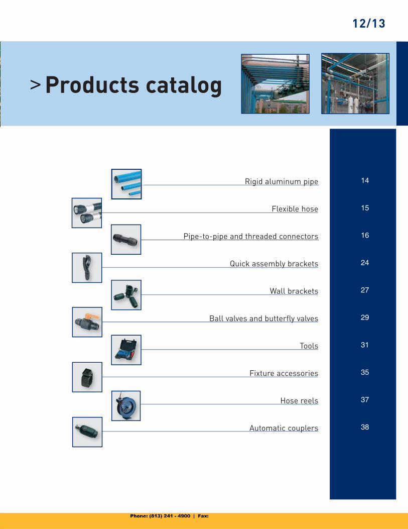
14
15
16
24
27
29
31
35
37
38
12/13
Rigid aluminum pipe
Flexible hose
Pipe-to-pipe and threaded connectors
Quick assembly brackets
Wall brackets
Ball valves and butterfly valves
Tools
Fixture accessories
Hose reels
Automatic couplers
> Products catalog
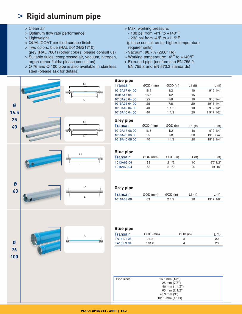
1013A17 04 00 16.5 1/2 10 9’ 9 1/4’’1004A17 04 16.5 1/2 15 1013A25 04 00 25 7/8 10 9’ 8 1/4’’1016A25 04 00 25 7/8 20 19’ 8 1/4’’1013A40 04 00 40 1 1/2 10 9’ 7 1/2’’1016A40 04 00 40 1 1/2 20 1 9’ 7 1/2’’
L1
L
Transair
Transair
Transair
L1
L
1013A17 06 00 16.5 1/2 10 9’ 9 1/4’’1016A25 06 00 25 7/8 20 19’ 9 3/4’’1016A40 06 00 40 1 1/2 20 19’ 8 1/4’’
Transair
L
L1
L1016A63 06 63 2 1/2 20 19’ 7 1/8’’
Transair
L1
L
1013A63 04 63 2 1/2 10 9’7 1/2’’1016A63 04 63 2 1/2 20 19’ 10’’
TA16 L1 04 76.3 3 20TA16 L3 04 101.8 4 20
Ø63
Ø76
100
Ø16.52540
> Rigid aluminum pipe
ØOD (mm) ØOD (in) L (ft)
L (ft)
> Clean air > Optimum flow rate performance > Lightweight > QUALICOAT certified surface finish > Two colors: blue (RAL 5012/BS1710),
grey (RAL 7001) (other colors: please consult us) > Suitable fluids: compressed air, vacuum, nitrogen,
argon (other fluids: please consult us) > Ø 76 and Ø 100 pipe is also available in stainless
steel (please ask for details)
> Max. working pressure: - 188 psi from -4°F to +140°F
- 232 psi from -4°F to +115°F (please consult us for higher temperature requirements)> Vacuum: 98.7% (29.6’’ Hg)> Working temperature: -4°F to +140°F > Extruded pipe (conforms to EN 755.2,
EN 755.8 and EN 573.3 standards)
Blue pipe L1 (ft)
Grey pipe
Blue pipe
Grey pipe
Blue pipe
L (ft)L1 (ft)
L (ft)L1 (ft)
L (ft)L1 (ft)
ØOD (mm) ØOD (in)
ØOD (mm) ØOD (in)
ØOD (mm) ØOD (in)
ØOD (mm) ØOD (in)
Pipe sizes: 16.5 mm (1/2’’) 25 mm (7/8’’) 40 mm (1 1/2’’) 63 mm (2 1/2’’) 76.3 mm (3’’) 101.8 mm (4’’ ID)
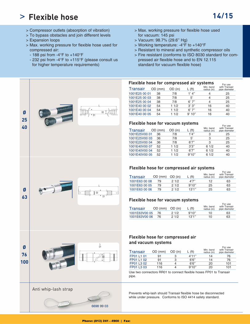
1001E63 00 08 79 2 1/2 4’7’’ 12 631001E63 00 05 79 2 1/2 9’10’’ 25 631001E63 00 06 79 2 1/2 13’1’’ 25 63
1001E63V00 05 76 2 1/2 9’10’’ 10 631001E63V00 06 76 2 1/2 13’1’’ 10 63
1001E25 00 01 38 7/8 1’ 4’’ 4 251001E25 00 03 38 7/8 5’ 4 251001E25 00 04 38 7/8 6’ 7’’ 4 251001E40 00 02 54 1 1/2 3’ 3’’ 16 401001E40 00 04 54 1 1/2 6’ 7’’ 16 401001E40 00 05 54 1 1/2 9’ 10’’ 16 40
1001E25V00 01 36 7/8 1’4’’ 3 251001E25V00 03 36 7/8 5’ 3 251001E25V00 04 36 7/8 6’7’’ 3 251001E40V00 07 52 1 1/2 3’3’’ 6 1/2 401001E40V00 04 52 1 1/2 6’7’’ 6 1/2 401001E40V00 05 52 1 1/2 9’10’’ 6 1/2 40
FP01 L1 01 91 3 4’11’’ 14 76FP01 L1 02 91 3 6’6’’ 14 76FP01 L3 02 116 4 6’6’’ 20 101FP01 L3 03 116 4 9’10’’ 20 101
Transair
Transair
Transair
Ø2540
Transair
Transair
L
Ø63
Ø76
100
14/15> Flexible hose
L (ft)Min. bend radius (in)
For usewith Transair pipe diameter
> Compressor outlets (absorption of vibration) > To bypass obstacles and join different levels > Expansion loops > Max. working pressure for flexible hose used for compressed air: - 188 psi from -4°F to +140°F - 232 psi from -4°F to +115°F (please consult us for higher temperature requirements)
> Max. working pressure for flexible hose usedfor vacuum: 145 psi
> Vacuum: 98.7% (29.6’’ Hg)> Working temperature: -4°F to +140°F> Resistant to mineral and synthetic compressor oils> Fire resistant (conforms to ISO 8030 standard for com-
pressed air flexible hose and to EN 12.115standard for vacuum flexible hose)
Flexible hose for compressed air systems
Flexible hose for vacuum systems
Flexible hose for vacuum systems
Flexible hose for compressed air systems
Anti whip-lash strapPrevents whip-lash should Transair flexible hose be disconnectedwhile under pressure. Conforms to ISO 4414 safety standard.
Use two connectors RR01 to connect flexible hoses FP01 to Transair pipe.
L (ft)
L (ft)
L (ft)
L (ft)
Flexible hose for compressed airand vacuum systems
Min. bend radius (in)
For usewith Transair pipe diameter
Min. bend radius (in)
For usewith Transair pipe diameter
Min. bend radius (in)
For usewith Transair pipe diameter
Min. bend radius (in)
For usewith Transair pipe diameter
whip lash strap
6698 99 03
L
L
D1
D2
D1
D2
D2D1
OD (mm) OD (in)
OD (mm) OD (in)
OD (mm) OD (in)
OD (mm) OD (in)
OD (mm) OD (in)
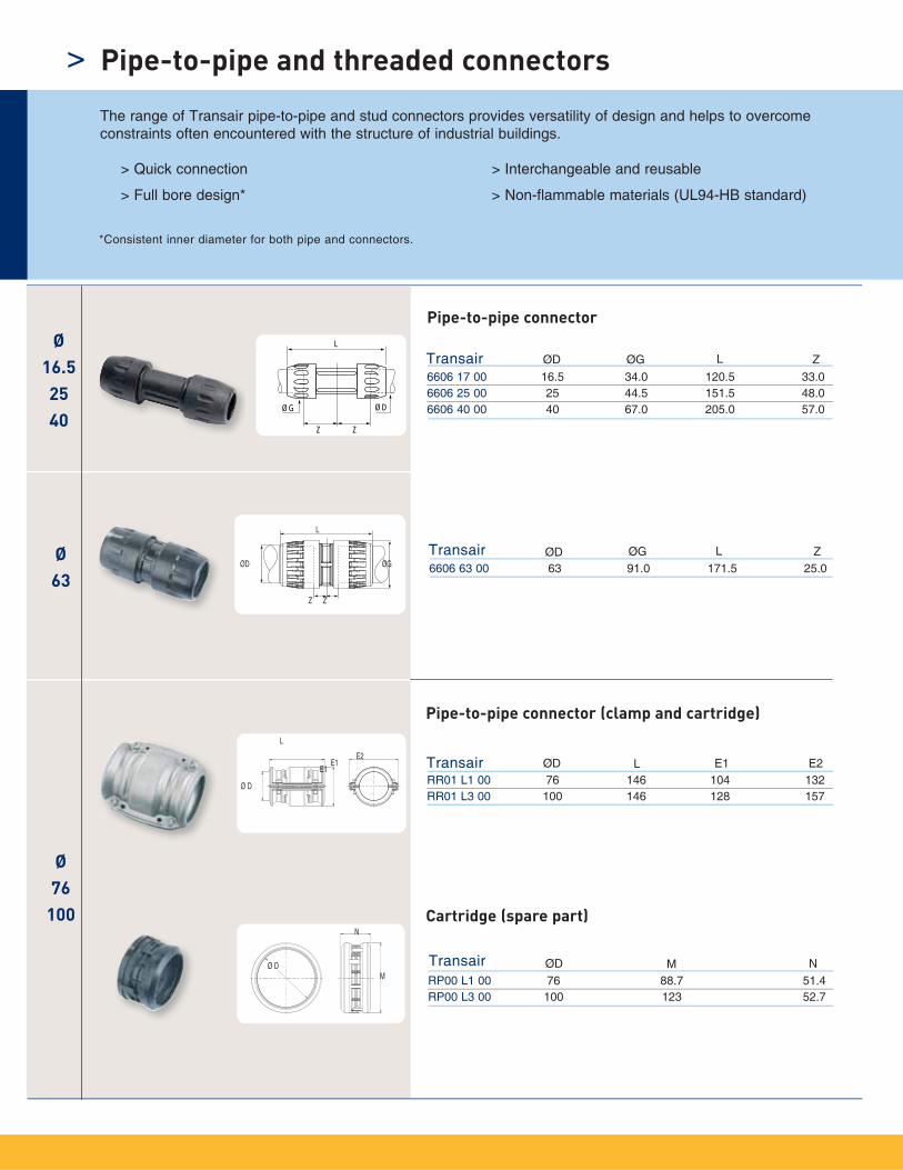
6606 17 00 16.5 34.0 120.5 33.06606 25 00 25 44.5 151.5 48.06606 40 00 40 67.0 205.0 57.0
TransairØ
16.52540
Ø63
Ø76
100
ØG
L
ØD
Z Z
6606 63 00 63 91.0 171.5 25.0
RR01 L1 00 76 146 104 132RR01 L3 00 100 146 128 157
Transair
Transair
L
E2E1
Ø D
E1
Ø D
N
M
ØD ØG ZL
ØD ØG ZL
ØD L E1 E2
RP00 L1 00 76 88.7 51.4RP00 L3 00 100 123 52.7
Transair ØD M N
L
Z Z
ØGØD
>
Pipe-to-pipe connector
Pipe-to-pipe and threaded connectors
> Quick connection
> Full bore design*
> Interchangeable and reusable
> Non-flammable materials (UL94-HB standard)
Pipe-to-pipe connector (clamp and cartridge)
Cartridge (spare part)
The range of Transair pipe-to-pipe and stud connectors provides versatility of design and helps to overcome constraints often encountered with the structure of industrial buildings.
*Consistent inner diameter for both pipe and connectors.
Ø63
Ø2540 ØG
L
ØD
Z Z
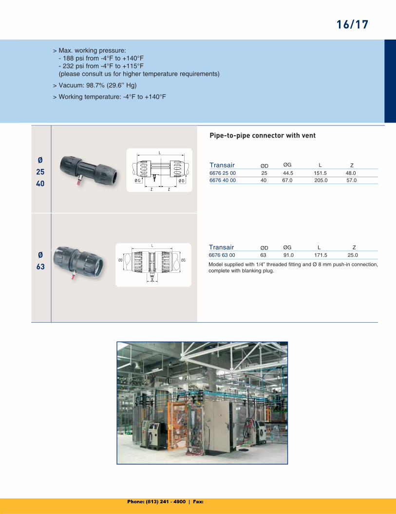
6676 25 00 25 44.5 151.5 48.06676 40 00 40 67.0 205.0 57.0
6676 63 00 63 91.0 171.5 25.0
Transair
Transair
ØD ØG ZL
ØD ØG ZLL
ØGØD
Z Z
16/17
Pipe-to-pipe connector with vent
> Max. working pressure: - 188 psi from -4°F to +140°F - 232 psi from -4°F to +115°F(please consult us for higher temperature requirements)
> Vacuum: 98.7% (29.6’’ Hg)
> Working temperature: -4°F to +140°F
Model supplied with 1/4” threaded fitting and Ø 8 mm push-in connection, complete with blanking plug.
Ø63
Ø76
100
Ø16.5254063
ØGL
Z
ØD
Z
H
CE
JZ2
Z1
L
ØDØG
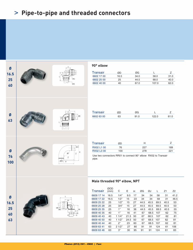
6602 17 00 16.5 34.0 58.0 31.06602 25 00 25 44.5 68.0 40.06602 40 00 40 67.0 107.0 62.0
Transair
6602 63 00 63 91.0 122.0 61.0
Transair
RX02 L1 00 76 227 189RX02 L3 00 100 278 221
Transair
Ø D
Ø D
90°H
H
ØD ØG ZL
ØD H
Ø16.52540
ØD ØG ZL
Z
Z
Z
Z
Z
ØDØG
L
L
6609 17 14 16.5 1/4’’ 9.5 17 34 34 58 31 41.26609 17 22 16.5 1/2’’ 15 23 34 34 58 31 46.56609 25 22 25 1/2’’ 15 27 44.5 45.5 69.5 40.5 53 6609 25 28 25 3/4’’ 15 27 44.5 45.5 69.5 40.5 53 6609 25 35 25 1’’ 16 36 44.5 45.5 69.5 40.5 55 6609 40 35 40 1’’ 16 41 67 68.5 107 62 75 6609 40 43 40 1 1/4’’ 21.5 50 67 68.5 107 62 816609 40 50 40 1 1/2’’ 24.5 50 67 68.5 107 62 816609 40 44 40 2’’ 23 60 67 68.5 107 62 816609 63 41 63 2 1/2’’ 27 80 91 91 124 61 1066609 63 46 63 3’’ 30 95 91 91 124 61 83
TransairØOD (mm) C L Z1 Z2ØJØGHE
> Pipe-to-pipe and threaded connectors
90° elbow
Male threaded 90° elbow, NPT
Use two connectors RR01 to connect 90° elbow RX02 to Transair pipe.
Ø63
ØDØG
L
Z
ØG
ØD
Z2
CE
H
J
ØG
L
Z
ØD
ZØ2540
Ø76
100
Ø2540
Ø63
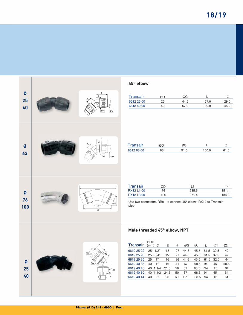
6612 63 00 63 91.0 100.0 61.0
Transair
6612 25 00 25 44.5 57.0 29.06612 40 00 40 67.0 90.0 45.0
Transair
RX12 L1 00 76 235.5 151.4RX12 L3 00 100 271.4 184.3
Transair
ØD ØG ZL
ØD L1 L2
ØD ØG ZL
135°
L2
ØD
6619 25 22 25 1/2’’ 15 27 44.5 45.5 61.5 32.5 426619 25 28 25 3/4’’ 15 27 44.5 45.5 61.5 32.5 426619 25 35 25 1’’ 16 36 44.5 45.5 61.5 32.5 44 6619 40 35 40 1’’ 16 41 67 68.5 94 45 58.5 6619 40 43 40 1 1/4’’ 21.5 50 67 68.5 94 45 64 6619 40 50 40 1 1/2’’ 24.5 50 67 68.5 94 45 64 6619 40 44 40 2’’ 23 60 67 68.5 94 45 61
TransairØOD (mm) C L Z1 Z2ØJØGHE
Male threaded 45° elbow, NPT
18/19
45° elbow
Use two connectors RR01 to connect 45° elbow RX12 to Transair pipe.
Ø76
100
Ø63
Ø16.52540
Ø76
100
Ø63
Ø162540
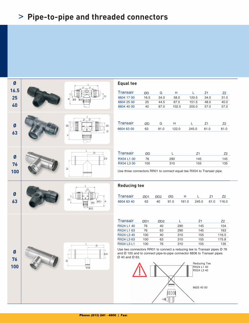
6604 17 00 16.5 34.0 58.0 120.5 34.0 31.06604 25 00 25 44.5 67.5 151.5 48.0 40.06604 40 00 40 67.0 102.5 205.0 57.0 57.0
Transair ØD G Z1H L Z2
6604 63 00 63 91.0 122.0 245.0 61.0 61.0
Transair
RX04 L1 00 76 290 145 145RX04 L3 00 100 310 155 135
Transair ØD L Z1 Z2
ØG
LZ1
ØDHZ2
Z1
Ø63
Ø16.52540
Ø63
Ø76
100
Ø76
100
ØG
L
Z1
ØD2
ØD1Z2
H 6604 63 40 63 40 91.0 161.0 245.0 61.0 116.0
Transair ØD1 ØG Z1H L Z2ØD2
RX24 L1 40 76 40 290 145 104RX24 L1 63 76 63 290 145 163RX24 L3 40 100 40 310 155 116.5RX24 L3 63 100 63 310 155 175.8RX04 L3 L1 100 76 310 155 135
Transair ØD1 LØD2 Z1 Z2
L
Z2
Z1
Ø D
Ø D2
LZ1
Ø D1
Z2
ØD G Z1H L Z2
LZ1 Z1
Z2
ØGØD
H
>
Equal tee
Reducing tee
Pipe-to-pipe and threaded connectors
Use three connectors RR01 to connect equal tee RX04 to Transair pipe.
Use two connectors RR01 to connect a reducing tee to Transair pipes Ø 76 and Ø 100 and to connect pipe-to-pipe connector 6606 to Transair pipes Ø 40 and Ø 63.
Reducing TeeRX24 L1 40RX24 L3 40
6625 40 00
ØG ØD2ØD1
Z
L
L
ØGØD2
Ø76
100
Ø16.52540
Ø63
Ø76
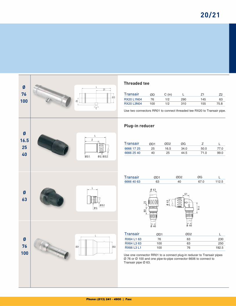
100 RX20 L1N04 76 1/2 290 145 63RX20 L3N04 100 1/2 310 155 75.8
Transair ØD C (in) Z1L Z2
6666 17 25 25 16.5 34.0 50.0 77.06666 25 40 40 25 44.5 71.0 99.0
Transair ØD1 ØD2 ZØG L
6666 40 63 63 40 67.0 112.5Transair ØD1 ØD2 ØG L
RX64 L1 63 76 63 230RX64 L3 63 100 63 250RX66 L3 L1 100 76 192.5
Transair ØD1 ØD2 L
C
Z2
Z1L
Ø D
Ø 6
3
Ø 40
61
116
2580
Ø 63
Ø 40
L
ØD1 ØD2
20/21
Threaded tee
Plug-in reducer
Use two connectors RR01 to connect threaded tee RX20 to Transair pipe.
Use one connector RR01 to a connect plug-in reducer to Transair pipes Ø 76 or Ø 100 and one pipe-to-pipe connector 6606 to connect to Transair pipe Ø 63.
Ø16.52540
Ø63
Ø76
100
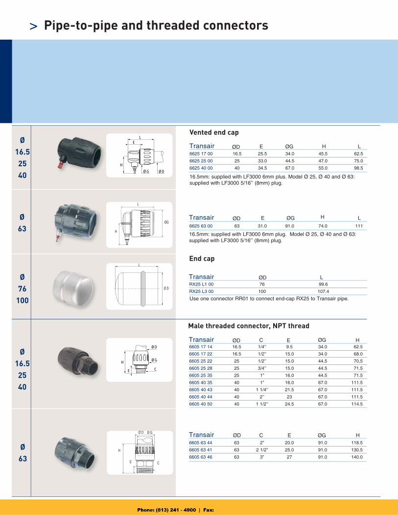
6625 17 00 16.5 25.5 34.0 45.5 62.5
6625 25 00 25 33.0 44.5 47.0 75.0
6625 40 00 40 34.5 67.0 55.0 98.5
Transair ØD ØGE H L
6625 63 00 63 31.0 91.0 74.0 111
Transair ØD ØGE H L
RX25 L1 00 76 99.6
RX25 L3 00 100 107.4
Transair ØD L
ØG
E
ØD
L
H
L
Ø D
Ø16.52540
ØG
E
ØD
C
H
Ø63
6605 17 14 16.5 1/4’’ 9.5 34.0 62.5
6605 17 22 16.5 1/2’’ 15.0 34.0 68.0
6605 25 22 25 1/2’’ 15.0 44.5 70,5
6605 25 28 25 3/4’’ 15.0 44.5 71.5
6605 25 35 25 1” 16.0 44.5 71.5
6605 40 35 40 1” 16.0 67.0 111.5
6605 40 43 40 1 1/4’’ 21.5 67.0 111.5
6605 40 44 40 2’’ 23 67.0 111.5
6605 40 50 40 1 1/2’’ 24.5 67.0 114.5
Transair ØD EC ØG H
6605 63 44 63 2” 20.0 91.0 118.5
6605 63 41 63 2 1/2” 25.0 91.0 130.5
6605 63 46 63 3” 27 91.0 140.0
Transair ØD EC H
L
ØG
H
Ø GØ D
H
E C
ØG
Ø16.52540
> Pipe-to-pipe and threaded connectors
Vented end cap
Male threaded connector, NPT thread
Use one connector RR01 to connect end-cap RX25 to Transair pipe.
16.5mm: supplied with LF3000 6mm plus. Model Ø 25, Ø 40 and Ø 63: supplied with LF3000 5/16’’ (8mm) plug.
16.5mm: supplied with LF3000 6mm plug. Model Ø 25, Ø 40 and Ø 63: supplied with LF3000 5/16’’ (8mm) plug.
End cap
Ø16.52540
Ø76
Ø2540
L1
Ø12
L2 N N N
ØG
ØD
L
Z Z
LZ
NC
L2
46
N N
L1
N N
NM
19,5
ZH
K
ØD
ØD
C
L
H
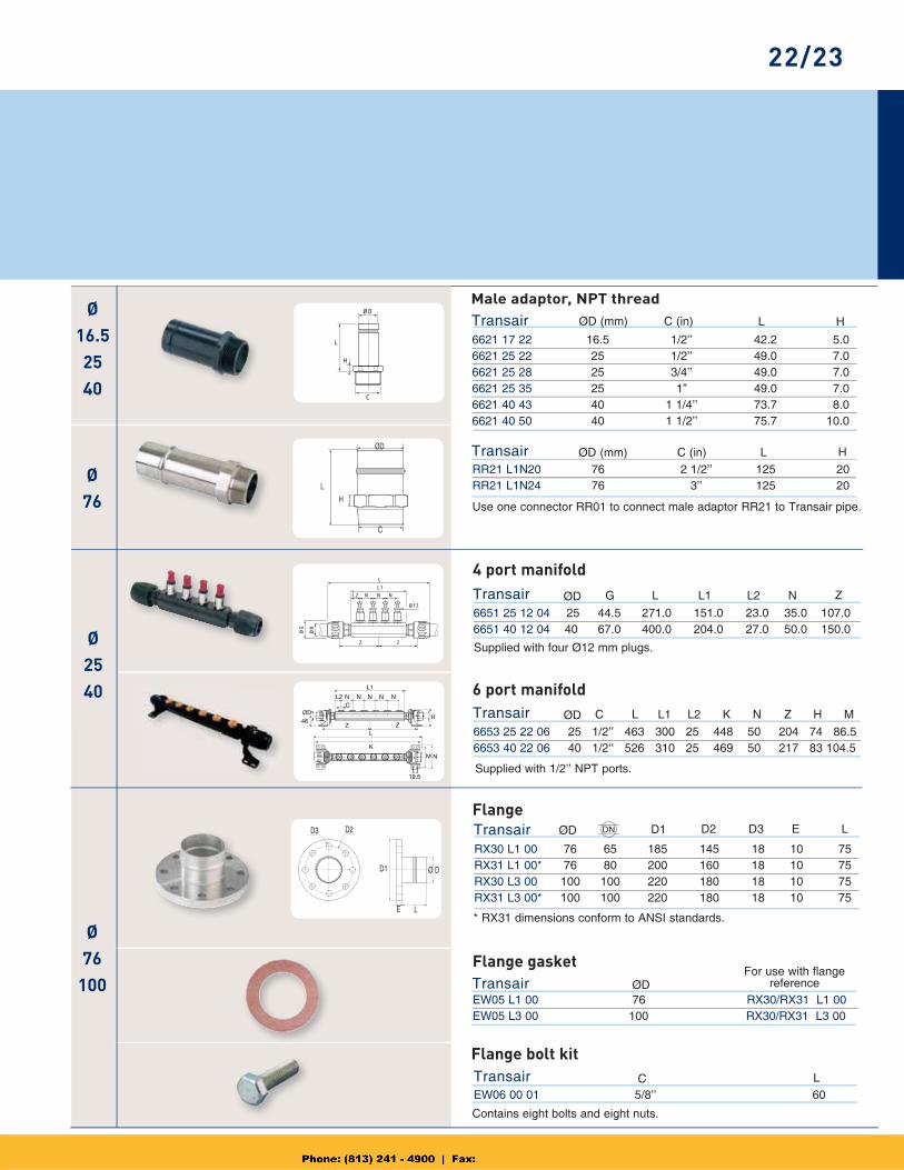
6621 17 22 16.5 1/2’’ 42.2 5.06621 25 22 25 1/2’’ 49.0 7.06621 25 28 25 3/4’’ 49.0 7.06621 25 35 25 1” 49.0 7.06621 40 43 40 1 1/4’’ 73.7 8.06621 40 50 40 1 1/2’’ 75.7 10.0
Transair ØD (mm) LC (in) H
RR21 L1N20 76 2 1/2’’ 125 20RR21 L1N24 76 3’’ 125 20
Transair ØD (mm) LC (in) H
6651 25 12 04 25 44.5 271.0 151.0 23.0 35.0 107.06651 40 12 04 40 67.0 400.0 204.0 27.0 50.0 150.0
6653 25 22 06 25 1/2’’ 463 300 25 448 50 204 74 86.56653 40 22 06 40 1/2 ‘‘ 526 310 25 469 50 217 83 104.5
Transair
Transair
ØD
ØD
L
L
G
C
Z
N Z H M
L1
L1
L2
L2
N
K
Ø76
100
RX30 L1 00 76 65 185 145 18 10 75RX31 L1 00* 76 80 200 160 18 10 75RX30 L3 00 100 100 220 180 18 10 75RX31 L3 00* 100 100 220 180 18 10 75
Transair ØD D1
EW05 L1 00 76 RX30/RX31 L1 00EW05 L3 00 100 RX30/RX31 L3 00
Transair ØD
EW06 00 01 5/8’’ 60
Transair C L
D2D3
D1 Ø D
LE
D2 D3 E LDN
ØD
L
H
C
22/23
Male adaptor, NPT thread
4 port manifold
6 port manifold
Supplied with four Ø12 mm plugs.
Supplied with 1/2’’ NPT ports.
Flange
* RX31 dimensions conform to ANSI standards.
Flange gasket
Flange bolt kit
Contains eight bolts and eight nuts.
Use one connector RR01 to connect male adaptor RR21 to Transair pipe.
For use with flange reference
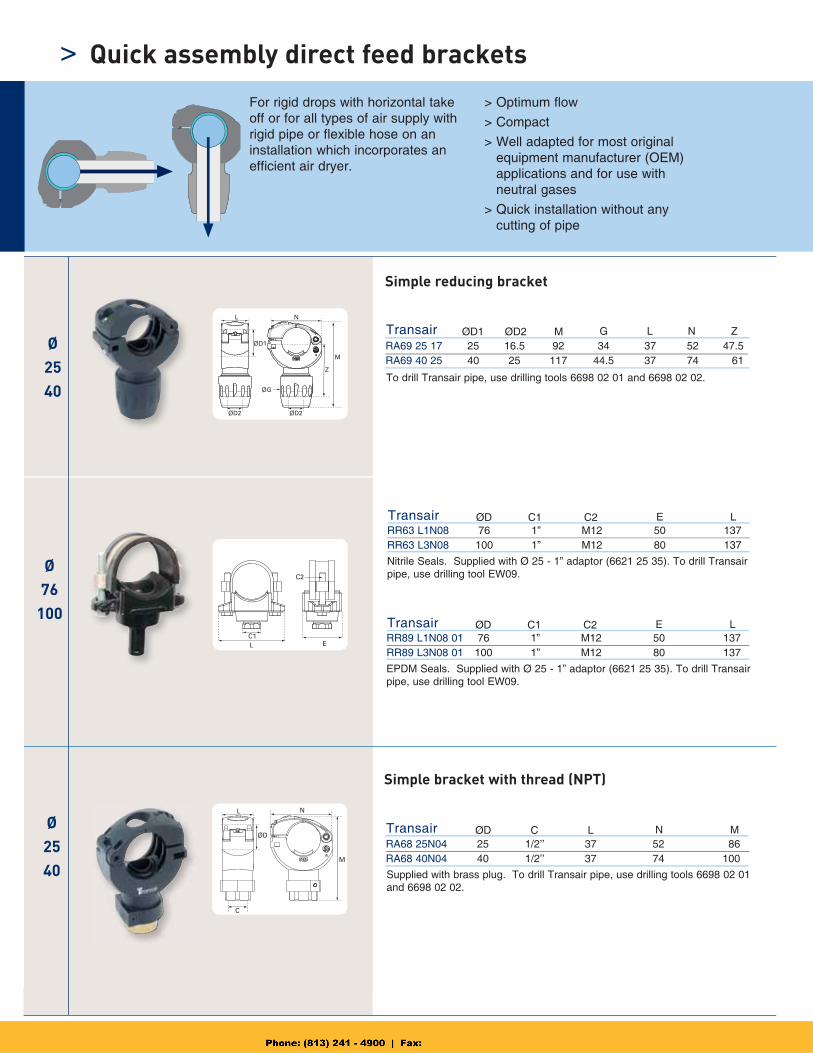
RA69 25 17 25 16.5 92 34 37 52 47.5RA69 40 25 40 25 117 44.5 37 74 61
Transair ØD1 ØD2 M G L N Z
Ø2540
Ø76
100
Ø2540
RR63 L1N08 76 1” M12 50 137RR63 L3N08 100 1” M12 80 137
RR89 L1N08 01 76 1” M12 50 137RR89 L3N08 01 100 1” M12 80 137
Transair
Transair
ØD
ØD
C1
C1
C2
C2
E
E
L
L
RA68 25N04 25 1/2’’ 37 52 86RA68 40N04 40 1/2’’ 37 74 100
Transair ØD C L N M
ØD1
ØG
L N
Z
M
ØD2 ØD2
LC1
E
C2
N
ØD
L
M
C
> Quick assembly direct feed brackets
Simple reducing bracket
Simple bracket with thread (NPT)
To drill Transair pipe, use drilling tools 6698 02 01 and 6698 02 02.
Nitrile Seals. Supplied with Ø 25 - 1” adaptor (6621 25 35). To drill Transair pipe, use drilling tool EW09.
EPDM Seals. Supplied with Ø 25 - 1” adaptor (6621 25 35). To drill Transair pipe, use drilling tool EW09.
Supplied with brass plug. To drill Transair pipe, use drilling tools 6698 02 01 and 6698 02 02.
For rigid drops with horizontal take off or for all types of air supply with rigid pipe or flexible hose on an installation which incorporates an efficient air dryer.
> Optimum flow
> Compact
> Well adapted for most original equipment manufacturer (OEM)applications and for use with neutral gases
> Quick installation without any cutting of pipe
Ø2540
Ø254063
Ø63
Ø2540
Ø63
D2
ØG
L N
MZ
ØD1
N
L2
L
C
L1
ØD1
M
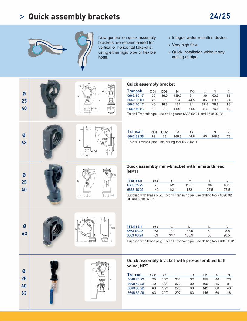
6668 25 22 25 1/2’’ 256 32 155 40 236668 40 22 40 1/2’’ 270 39 162 45 316668 63 22 63 1/2’’ 275 63 142 60 486668 63 28 63 3/4’’ 297 63 146 60 48
Transair ØD1 C L L1 L2 M N
6662 63 25 63 25 166.5 44.5 50 108.5 75Transair ØD1 ØD2 M G L N Z
6663 25 22 25 1/2’’ 117.5 36 63.56663 40 22 40 1/2’’ 132 37.5 76.5
Transair ØD1 C M L N
6663 63 22 63 1/2’’ 138.9 50 98.56663 63 28 63 3/4’’ 138.9 50 98.5
Transair ØD1 C M L N
> 24/25Quick assembly brackets
New generation quick assemblybrackets are recommended forvertical or horizontal take-offs,using either rigid pipe or flexiblehose.
> Integral water retention device
> Very high flow
> Quick installation without any cutting of pipe
Quick assembly bracket
Quick assembly mini-bracket with female thread (NPT)
Quick assembly bracket with pre-assembled ball valve, NPT
To drill Transair pipe, use drilling tools 6698 02 01 and 6698 02 02.
To drill Transair pipe, use drilling tool 6698 02 02.
Supplied with brass plug. To drill Transair pipe, use drilling tool 6698 02 01.
Supplied with brass plug. To drill Transair pipe, use drilling tools 6698 02 01 and 6698 02 02.
6662 25 17 25 16.5 139.5 34 36 63.5 826662 25 00 25 25 134 44.5 36 63.5 746662 40 17 40 16.5 154 34 37.5 76.5 896662 40 25 40 25 149.5 44.5 37.5 76.5 82
Transair ØD1 ØD2 M ØG L N Z
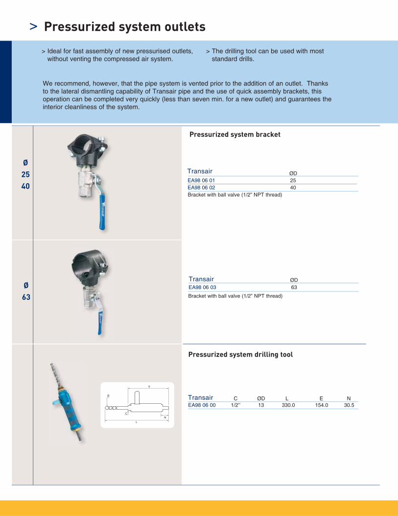
EA98 06 01 25EA98 06 02 40
Transair ØD
EA98 06 03 63
Transair ØD
EA98 06 00 1/2’’ 13 330.0 154.0 30.5Transair ØDC L E N
Ø63
Ø2540
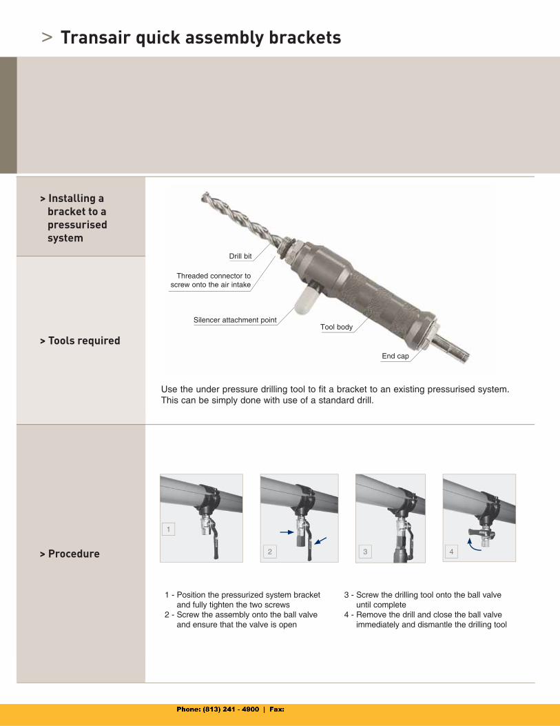
> Pressurized system outlets
> Ideal for fast assembly of new pressurised outlets, without venting the compressed air system.
> The drilling tool can be used with moststandard drills.
We recommend, however, that the pipe system is vented prior to the addition of an outlet. Thanks to the lateral dismantling capability of Transair pipe and the use of quick assembly brackets, this operation can be completed very quickly (less than seven min. for a new outlet) and guarantees the interior cleanliness of the system.
Pressurized system bracket
Pressurized system drilling tool
Bracket with ball valve (1/2” NPT thread)
Bracket with ball valve (1/2” NPT thread)
H
K N C2
ØG
ØD
C1
66.5
19,5
C346K
N
19,5
M
H
C1
C2
N
K
46 C2C1
H19,5
66,5
Z
ØD
N
M
C1
C2
H
K
19,5
C3
66,5
Z19,5
N
K
46
H
C2 C1
ØD
C246 C3
C1
H
K
N
19,5
M
Transair ØD C1 H Z K N
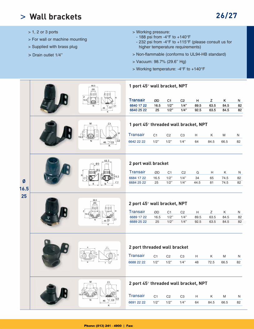
6684 17 22 16.5 1/2’’ 1/4’’ 34 65 74.5 826684 25 22 25 1/2’’ 1/4’’ 44.5 81 74.5 82
Transair C1 C2 H K N
6688 22 22 1/2’’ 1/2’’ 1/4’’ 48 72.5 66.5 82
6691 22 22 1/2’’ 1/2’’ 1/4’’ 64 84.5 66.5 82
6642 22 22 1/2’’ 1/2’’ 1/4’’ 64 84.5 66.5 82
C2
Transair ØD C1 G H K NC2
C3
Transair
Transair
M
C1
C1
C2
C2
H
H
K
K
N
N
C3
C3
M
M
Ø16.525
6640 17 22 16.5 1/2’’ 1/4’’ 89.5 63.5 84.5 826640 25 22 25 1/2’’ 1/4’’ 92.5 63.5 84.5 82
Transair ØD C1 H Z K NC2
6689 17 22 16.5 1/2’’ 1/4’’ 89.5 63.5 84.5 826689 25 22 25 1/2’’ 1/4’’ 92.5 63.5 84.5 82
Transair ØD C1 H Z K NC2
6640 17 22 16.5 1/2’’ 1/4’’ 89.5 63.5 84.5 826640 25 22 25 1/2’’ 1/4’’ 92.5 63.5 84.5 82
> 26/27Wall brackets
> 1, 2 or 3 ports
> For wall or machine mounting
> Supplied with brass plug
> Drain outlet 1/4’’
> Working pressure: - 188 psi from -4°F to +140°F - 232 psi from -4°F to +115°F (please consult us for higher temperature requirements)
> Non-flammable (conforms to UL94-HB standard)
> Vacuum: 98.7% (29.6’’ Hg)
> Working temperature: -4°F to +140°F
1 port 45° wall bracket, NPT
2 port 45° wall bracket, NPT
2 port wall bracket
1 port 45° threaded wall bracket, NPT
2 port threaded wall bracket
2 port 45° threaded wall bracket, NPT
Transair ØD C1 H Z K N
Transair C1 C2 H K N
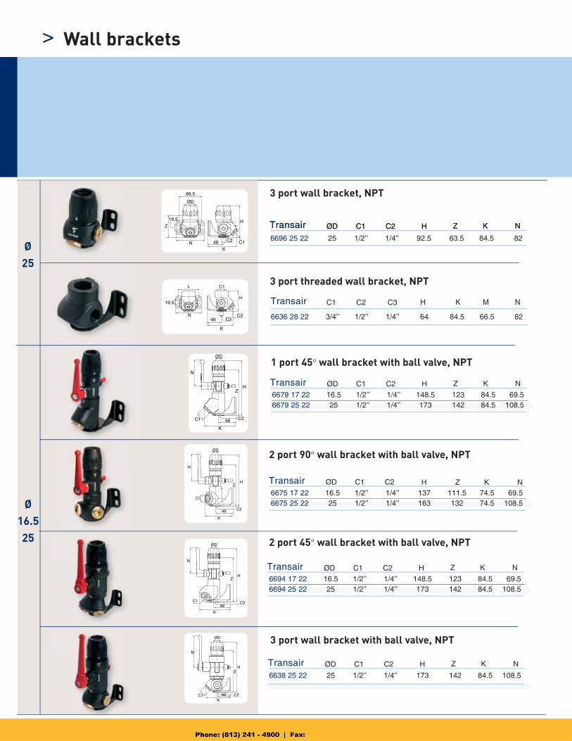
6636 28 22 3/4’’ 1/2’’ 1/4’’ 64 84.5 66.5 82
6638 25 22 25 1/2’’ 1/4’’ 173 142 84.5 108.5
6696 25 22 25 1/2’’ 1/4’’ 92.5 63.5 84.5 82
C2
C3 M
H Z NK
Transair
Transair
Transair
Transair
ØD
ØD
ØD
ØD
C1
C1
C1
C1
H
H
H
Z
Z
Z
K
K
K
N
N
N
C2
C2
C2
C2
6694 17 22 16.5 1/2’’ 1/4’’ 148.5 123 84.5 69.56694 25 22 25 1/2’’ 1/4’’ 173 142 84.5 108.5
6675 17 22 16.5 1/2’’ 1/4’’ 137 111.5 74.5 69.56675 25 22 25 1/2’’ 1/4’’ 163 132 74.5 108.5
6679 17 22 16.5 1/2’’ 1/4’’ 148.5 123 84.5 69.56679 25 22 25 1/2’’ 1/4’’ 173 142 84.5 108.5
Transair ØD C1 H Z K NC2
Ø25
Ø16.525
C1C2
KN
19,5
Z
66,5
46
H
ØD
L
N
K
C3C2
C1
46
19,5H
HZ
C246
K
C1
N
ØD
46C2C1
N
K
HZ
ØD
H
K46 C2
ØD
C1
N
Z
46 C2
K
C1
N
HZ
ØD
> Wall brackets
3 port wall bracket, NPT
2 port 45° wall bracket with ball valve, NPT
3 port wall bracket with ball valve, NPT
3 port threaded wall bracket, NPT
1 port 45° wall bracket with ball valve, NPT
2 port 90° wall bracket with ball valve, NPT
ØG
L
Z2Z1
ØD
N
Ø76
100
Ø63
Ø16.525
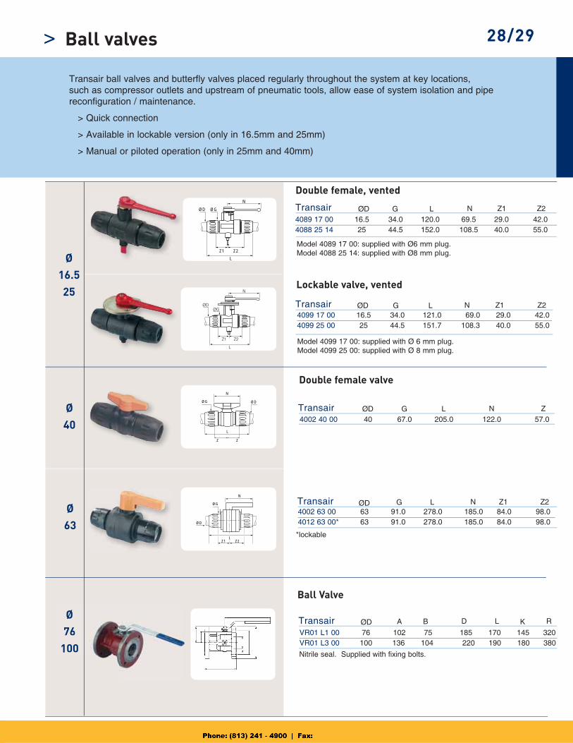
4089 17 00 16.5 34.0 120.0 69.5 29.0 42.04088 25 14 25 44.5 152.0 108.5 40.0 55.0
Transair ØD G L N
4099 17 00 16.5 34.0 121.0 69.0 29.0 42.04099 25 00 25 44.5 151.7 108.3 40.0 55.0
4002 40 00 40 67.0 205.0 122.0 57.0
Transair
VR01 L1 00 76 102 75 185 170 145 320VR01 L3 00 100 136 104 220 190 180 380
Transair ØD
ØG
Z Z
L
ØD
N
ØG
L
N
ØD
Z1 Z2
Z1 Z2
ØD G L N Z
4002 63 00 63 91.0 278.0 185.0 84.0 98.04012 63 00* 63 91.0 278.0 185.0 84.0 98.0
Transair ØD G L N Z1 Z2
Ø40
Transair ØD G L N Z1 Z2
B D L RØ76
100
A K
28/29
Model 4089 17 00: supplied with Ø6 mm plug.Model 4088 25 14: supplied with Ø8 mm plug.
Nitrile seal. Supplied with fixing bolts.
Model 4099 17 00: supplied with Ø 6 mm plug.Model 4099 25 00: supplied with Ø 8 mm plug.
*lockable
Transair ball valves and butterfly valves placed regularly throughout the system at key locations,such as compressor outlets and upstream of pneumatic tools, allow ease of system isolation and pipereconfiguration / maintenance.
> Quick connection
> Available in lockable version (only in 16.5mm and 25mm)
> Manual or piloted operation (only in 25mm and 40mm)
Double female, vented
Lockable valve, vented
Double female valve
Ball Valve
Ball valves>
Ø40
Ø76
100
ØG
L
Z Z
ØD
Ø4 Ø4
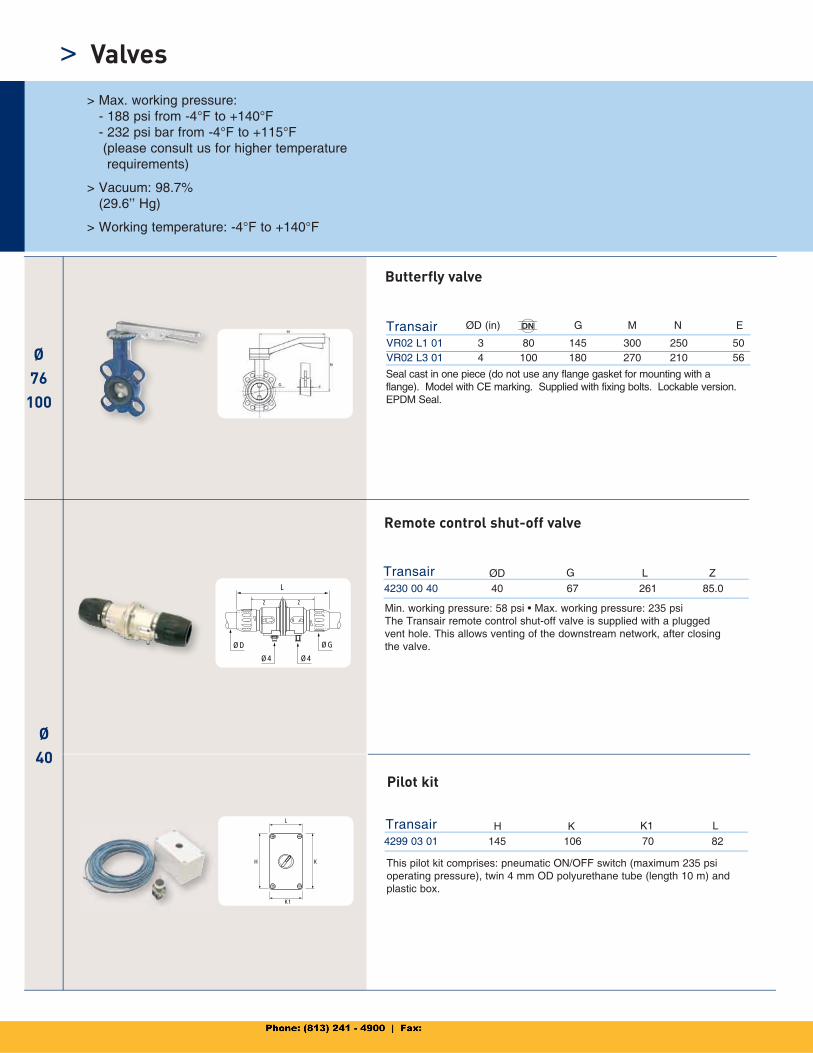
4230 00 40 40 67 261 85.0
Transair
Transair
ØD G L Z
H K
L
K1
4299 03 01 145 106 70 82
Transair H K K1 L
Min. working pressure: 58 psi • Max. working pressure: 235 psiThe Transair remote control shut-off valve is supplied with a plugged vent hole. This allows venting of the downstream network, after closing the valve.
This pilot kit comprises: pneumatic ON/OFF switch (maximum 235 psi operating pressure), twin 4 mm OD polyurethane tube (length 10 m) and plastic box.
Remote control shut-off valve
Butterfly valve
Pilot kit
VR02 L1 01 3 80 145 300 250 50VR02 L3 01 4 100 180 270 210 56
ØD (in) DN G M N E
Seal cast in one piece (do not use any flange gasket for mounting with a flange). Model with CE marking. Supplied with fixing bolts. Lockable version. EPDM Seal.
> Valves> Max. working pressure:
- 188 psi from -4°F to +140°F - 232 psi bar from -4°F to +115°F (please consult us for higher temperature requirements)
> Vacuum: 98.7% (29.6’’ Hg)
> Working temperature: -4°F to +140°F
Ø76
100
Ø63
Ø162540 Ø
16.5to40
Ø16.5
to100
Ø63
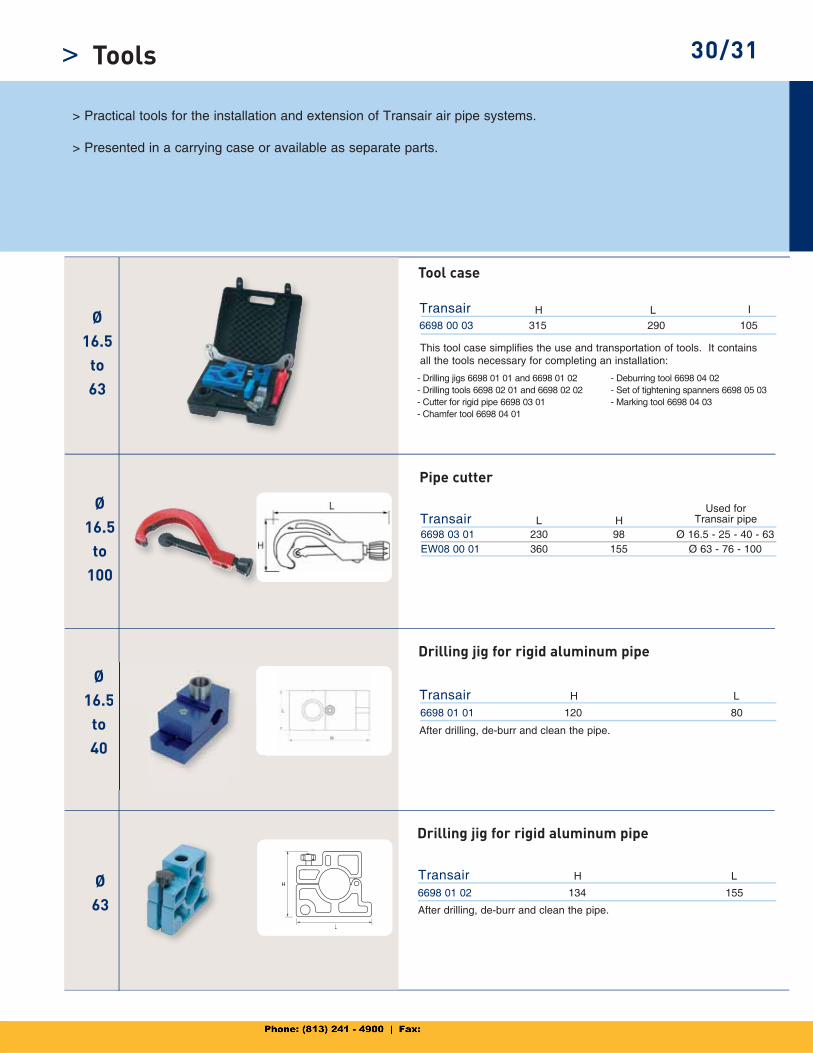
6698 00 03 315 290 105 Ø
16.5to63
6698 03 01 230 98 Ø 16.5 - 25 - 40 - 63EW08 00 01 360 155 Ø 63 - 76 - 100
Transair L
Transair H L I
H
H
L
6698 01 02 134 155
Transair H L
6698 01 01 120 80
Transair H L5
30/31
> Practical tools for the installation and extension of Transair air pipe systems.
> Presented in a carrying case or available as separate parts.
Tool case
Pipe cutter
Drilling jig for rigid aluminum pipe
After drilling, de-burr and clean the pipe.
Drilling jig for rigid aluminum pipe
After drilling, de-burr and clean the pipe.
- Drilling jigs 6698 01 01 and 6698 01 02- Drilling tools 6698 02 01 and 6698 02 02- Cutter for rigid pipe 6698 03 01- Chamfer tool 6698 04 01
- Deburring tool 6698 04 02- Set of tightening spanners 6698 05 03- Marking tool 6698 04 03
This tool case simplifies the use and transportation of tools. It contains all the tools necessary for completing an installation:
Used forTransair pipe
Tools>
Ø25
Ø40 63
Ø16.52540
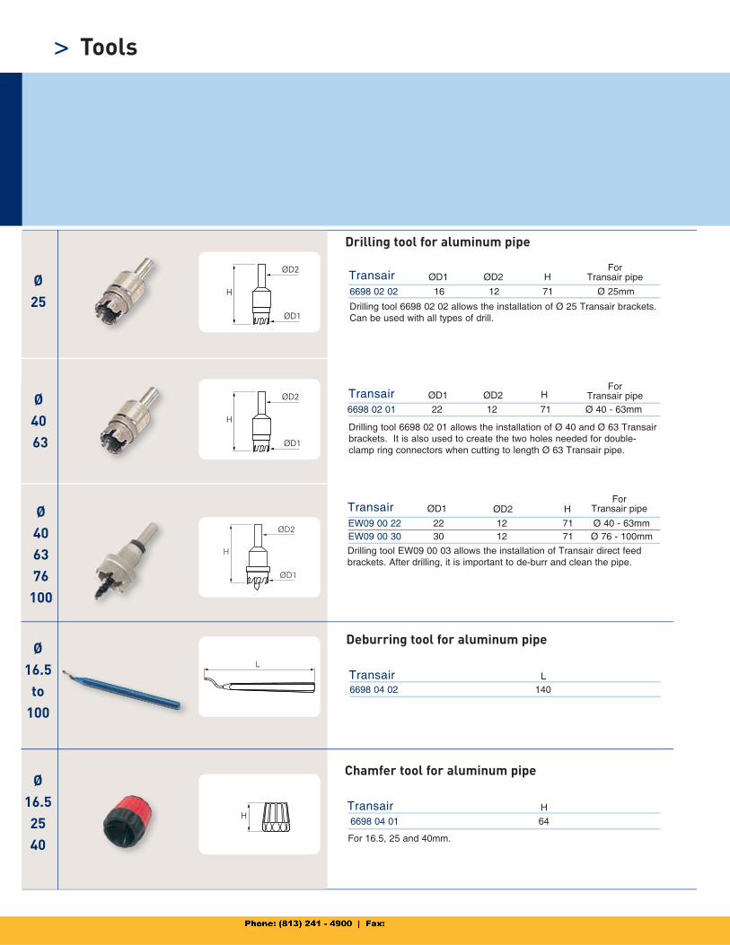
EW09 00 22 22 12 71 Ø 40 - 63mmEW09 00 30 30 12 71 Ø 76 - 100mm
Ø40 63 76
100
6698 02 02 16 12 71 Ø 25mm
6698 02 01 22 12 71 Ø 40 - 63mm
Transair ØD1 ØD2 H
6698 04 02 140
Transair L
6698 04 01 64
Transair H
Transair ØD1 ØD2 H
Transair ØD1 ØD2 H
Ø16.5
to 100
> Tools
Drilling tool 6698 02 02 allows the installation of Ø 25 Transair brackets. Can be used with all types of drill.
Drilling tool for aluminum pipe
Deburring tool for aluminum pipe
Chamfer tool for aluminum pipe
Drilling tool 6698 02 01 allows the installation of Ø 40 and Ø 63 Transair brackets. It is also used to create the two holes needed for double-clamp ring connectors when cutting to length Ø 63 Transair pipe.
ForTransair pipe
Drilling tool EW09 00 03 allows the installation of Transair direct feed brackets. After drilling, it is important to de-burr and clean the pipe.
ForTransair pipe
ForTransair pipe
For 16.5, 25 and 40mm.
Ø63
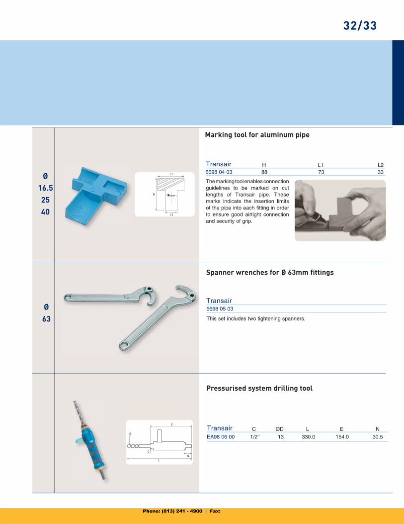
6698 04 03 88 73 33Transair H
L1
L2
H
L1 L2
6698 05 03Transair
EA98 06 00 1/2’’ 13 330.0 154.0 30.5
Transair ØDC L E N
Ø16.52540
32/33
The marking tool enables connectionguidelines to be marked on cut lengths of Transair pipe. These marks indicate the insertion limits of the pipe into each fitting in order to ensure good airtight connection and security of grip.
Marking tool for aluminum pipe
Spanner wrenches for Ø 63mm fittings
This set includes two tightening spanners.
Pressurised system drilling tool
Ø63
Ø76
100
Ø16.52540
Ø76
100
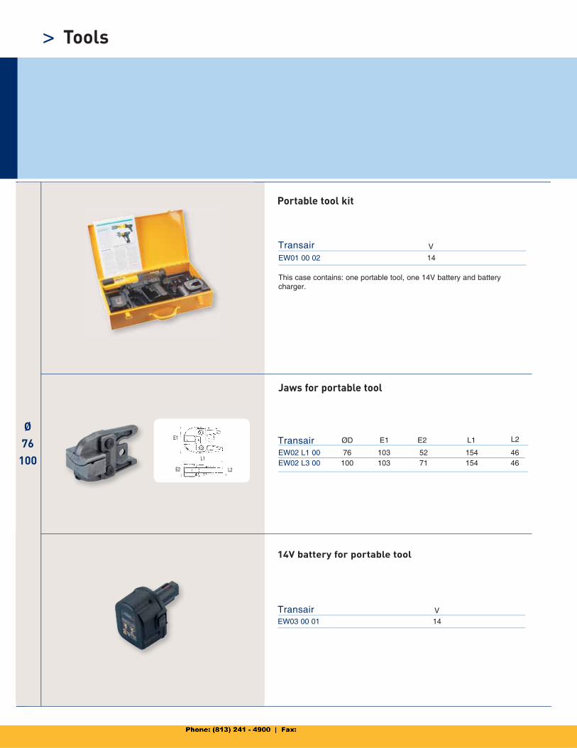
EW01 00 02 14
Transair V
EW02 L1 00 76 103 52 154 46EW02 L3 00 100 103 71 154 46
Transair ØD E1 E2 L1 L2
EW03 00 01 14
Transair
E1
L1
L2E2
V
> Tools
Portable tool kit
This case contains: one portable tool, one 14V battery and battery charger.
Jaws for portable tool
14V battery for portable tool
6697 17 01 16.5 1/4’’ 46 61 30 32.5
6697 25 01 25 1/4’’ 46 65.5 30 38.5
6697 40 01 40 1/4’’ 46 74.5 30 50
Transair C H1 LC
L
ØD
K
HH1
C
L
ØD
K
HH1
Ø DC
ER01 L1 00 76 3/8’’
ER01 L3 00 100 3/8’’
Transair ØD C
ØD H K
6697 63 01 63 3/8’’ 90 127.5 30 73.5
Transair C H1 LØD H K
Ø16.52540
Ø63
Ø76
100
Ø76
100
EX01 L1 00 76 3/8’’
EX01 L3 00 100 3/8’’
Transair ØD C
34/35
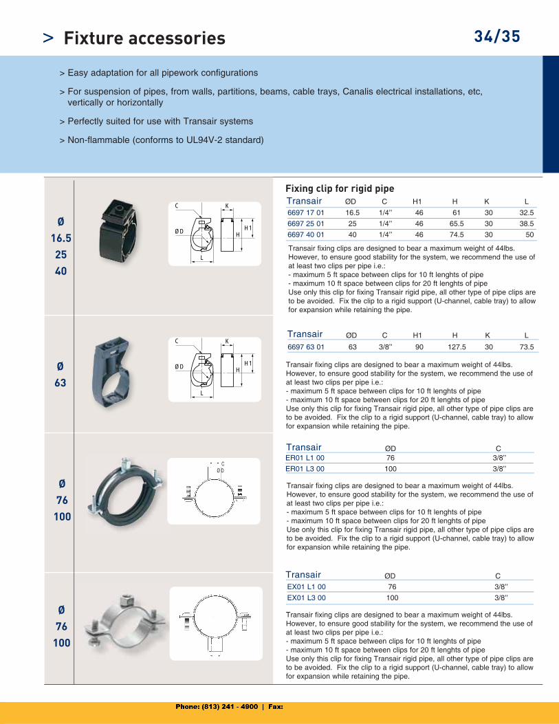
> Easy adaptation for all pipework configurations
> For suspension of pipes, from walls, partitions, beams, cable trays, Canalis electrical installations, etc,vertically or horizontally
> Perfectly suited for use with Transair systems
> Non-flammable (conforms to UL94V-2 standard)
Fixing clip for rigid pipe
Transair fixing clips are designed to bear a maximum weight of 44lbs. However, to ensure good stability for the system, we recommend the use of at least two clips per pipe i.e.: - maximum 5 ft space between clips for 10 ft lenghts of pipe - maximum 10 ft space between clips for 20 ft lenghts of pipe Use only this clip for fixing Transair rigid pipe, all other type of pipe clips are to be avoided. Fix the clip to a rigid support (U-channel, cable tray) to allow for expansion while retaining the pipe.
Transair fixing clips are designed to bear a maximum weight of 44lbs. However, to ensure good stability for the system, we recommend the use of at least two clips per pipe i.e.: - maximum 5 ft space between clips for 10 ft lenghts of pipe - maximum 10 ft space between clips for 20 ft lenghts of pipe Use only this clip for fixing Transair rigid pipe, all other type of pipe clips are to be avoided. Fix the clip to a rigid support (U-channel, cable tray) to allow for expansion while retaining the pipe.
Transair fixing clips are designed to bear a maximum weight of 44lbs. However, to ensure good stability for the system, we recommend the use of at least two clips per pipe i.e.: - maximum 5 ft space between clips for 10 ft lenghts of pipe - maximum 10 ft space between clips for 20 ft lenghts of pipe Use only this clip for fixing Transair rigid pipe, all other type of pipe clips are to be avoided. Fix the clip to a rigid support (U-channel, cable tray) to allow for expansion while retaining the pipe.
Transair fixing clips are designed to bear a maximum weight of 44lbs. However, to ensure good stability for the system, we recommend the use of at least two clips per pipe i.e.: - maximum 5 ft space between clips for 10 ft lenghts of pipe - maximum 10 ft space between clips for 20 ft lenghts of pipe Use only this clip for fixing Transair rigid pipe, all other type of pipe clips are to be avoided. Fix the clip to a rigid support (U-channel, cable tray) to allow for expansion while retaining the pipe.
Fixture accessories>
H H1
ØD
L K 6697 00 03 11 49.5 44 34 33
Transair ØD H1 LH K
L
L1
H
L
H
6699 01 01 25 6’6’’ 25
Transair L(ft)H L1
6699 01 02 106 40
Transair LH
90mm
46mm
44mm
Ø63 Ø40
Ø16.5
to 63
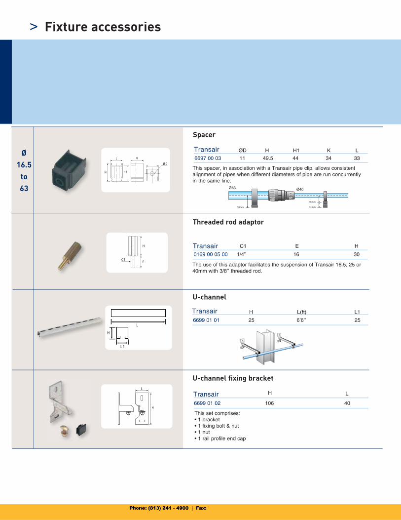
Spacer
This spacer, in association with a Transair pipe clip, allows consistent alignment of pipes when different diameters of pipe are run concurrently in the same line.
U-channel fixing bracket
This set comprises: • 1 bracket • 1 fixing bolt & nut• 1 nut • 1 rail profile end cap
H
C1E
0169 00 05 00 1/4’’ 16 30
Transair HC1 E
Threaded rod adaptor
The use of this adaptor facilitates the suspension of Transair 16.5, 25 or 40mm with 3/8’’ threaded rod.
U-channel
Fixture accessories>
L
H
ØD
L
H
ØD
6698 11 11 3/8 250 251 300
Transair H L
6698 11 12 3/8 250 251 390
Transair H L
50 ft
25 ft
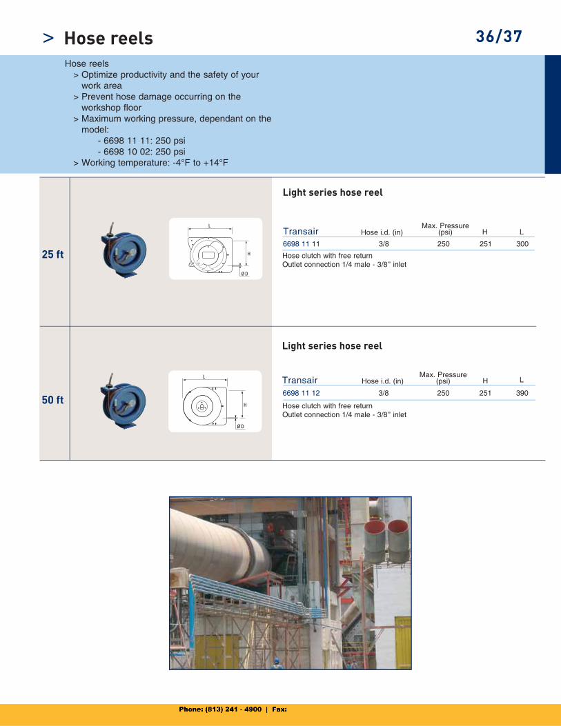
> 36/37Hose reels > Optimize productivity and the safety of your
work area > Prevent hose damage occurring on the
workshop floor > Maximum working pressure, dependant on the
model: - 6698 11 11: 250 psi - 6698 10 02: 250 psi > Working temperature: -4°F to +14°F
Light series hose reel
Hose clutch with free returnOutlet connection 1/4 male - 3/8’’ inlet
Hose i.d. (in)
Light series hose reel
Hose clutch with free returnOutlet connection 1/4 male - 3/8’’ inlet
Hose i.d. (in)Max. Pressure
(psi)
Max. Pressure (psi)
Hose reels
ARO1/4’’
ISO B3/8’’
ISO B1/4’’
Safety
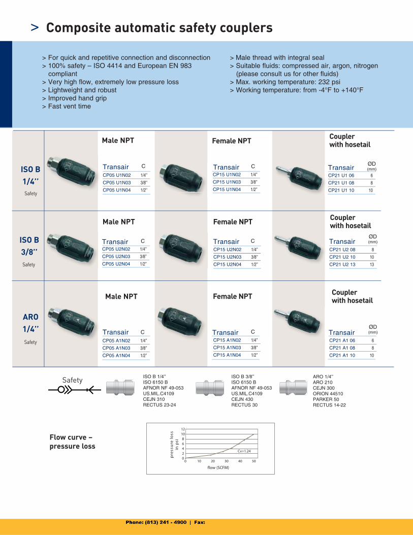
> For quick and repetitive connection and disconnection> 100% safety – ISO 4414 and European EN 983 compliant> Very high flow, extremely low pressure loss> Lightweight and robust > Improved hand grip> Fast vent time
> Male thread with integral seal> Suitable fluids: compressed air, argon, nitrogen (please consult us for other fluids) > Max. working temperature: 232 psi > Working temperature: from -4°F to +140°F
Flow curve –pressure loss
ISO B 3/8’’ISO 6150 BAFNOR NF 49-053US.MIL.C4109CEJN 430RECTUS 30
Male NPT Female NPT Couplerwith hosetail
Male NPT Female NPT Couplerwith hosetail
Male NPT Female NPT Couplerwith hosetail
SafetyISO B 1/4’’ISO 6150 BAFNOR NF 49-053US.MIL.C4109CEJN 310RECTUS 23-24
ARO 1/4’’ARO 210CEJN 300ORION 44510PARKER 50RECTUS 14-22
Safety
Safety
Composite automatic safety couplers>
Transair
Transair
Transair
Transair
Transair
Transair
Transair
Transair
Transair
CP05 U1N02 1/4’’
CP05 U1N03 3/8’’
CP05 U1N04 1/2’’
CP15 U1N02 1/4’’
CP15 U1N03 3/8’’
CP15 U1N04 1/2’’
CP21 U1 06 6
CP21 U1 08 8
CP21 U1 10 10
CP05 U2N02 1/4’’
CP05 U2N03 3/8’’
CP05 U2N04 1/2’’
CP15 U2N02 1/4’’
CP15 U2N03 3/8’’
CP15 U2N04 1/2’’
CP21 U2 08 8
CP21 U2 10 10
CP21 U2 13 13
CP05 A1N02 1/4’’
CP05 A1N03 3/8’’
CP05 A1N04 1/2’’
CP15 A1N02 1/4’’
CP15 A1N03 3/8’’
CP15 A1N04 1/2’’
CP21 A1 06 6
CP21 A1 08 8
CP21 A1 10 10
C
C
C
C
C
C
ØD (mm)
ØD (mm)
ØD (mm)
flow (SCFM)
12108642
0 10 20 30 40 50
ssol e r
usse rp
isp
ni
0
Cv=1.24•
••
•• •
•
•
ISO B
3/8’’
ISO B
1/4’’
ISO B 1/4’’
ISO B 3/8’’
ARO1/4’’
100/10138/39
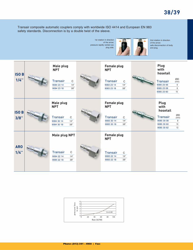
Transair composite automatic couplers comply with worldwide ISO 4414 and European EN 983safety standards. Disconnection is by a double twist of the sleeve.
1st rotation in directionof the arrow:
pressure rapidly vented out,plug side.
2nd rotation in directionof the arrow:safe disconnection of bodyand plug.
Male plugNPT
Female plug NPT
Plugwithhosetail
Male plugNPT
Female plug NPT
Male plug NPT Female plug NPT
Plugwithhosetail
ØD (mm)Transair
Transair
Transair
Transair
Transair
Transair
Transair
Transair
9084 23 14 1/4’’
9084 23 18 3/8’’
9083 23 14 1/4’’
9083 23 18 3/8’’
9085 23 56 6
9085 23 08 8
9085 23 60 10
9084 30 14 1/4’’
9084 30 18 3/8’’
9083 30 14 1/4’’
9083 30 18 3/8’’
9085 30 08 8
9085 30 60 10
9085 30 62 13
9084 22 14 1/4’’
9084 22 18 3/8’’
9083 22 14 1/4’’
9083 22 18 3/8’’
C
C
C
C
C
C
ØD (mm)
flow (SCFM)
ssol er
uss erp
isp
ni
12108642
0•
20 40 60 80 1000
Cv=2.49•
••
•• •
•

TransairOptimal Machine and Tool Effi ciency
The clean air quality and “full bore” design of Transair provides optimal machine and tool effi ciency. Transair’s aluminum pipe ensures a total absence of corrosion. The inner pipe surface consistently delivers clean com-pressed air. Transair prevents the problems caused by rust, which affects galvanized steel systems. Due to consistent clean quality air, from compressor outlets to machines, Transair aluminum pipe ensures higher longevity of equipment and avoids frequent changes of fi ltration elements.
The “full bore” design of Transair’s components, the low friction coeffi cient of aluminum pipe, and the sealing characteristics of the system ensure optimal and constant fl ow throughout. Due to its innovative technology, Transair gives better performance in terms of improved fl ow and reduced pressure drop.
Example: • A 63mm Transair system gives a fl ow performance better than that of a nominal (2 1/2”) galvanized steel system.
Example:• S teel pipe can erode by a 40% factor over its lifetime. Transair maintains its smooth bore through out its lifetime.
ØGL
Z
ØD
Z
42
43
44
46
50
52
55
59
61
62
65
67
68
71
72
74
76
77
81
83
40/41
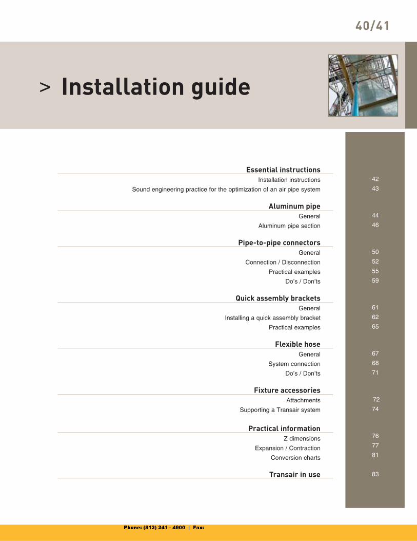
> Installation guide
Essential instructionsInstallation instructions
Sound engineering practice for the optimization of an air pipe system
Aluminum pipeGeneral
Aluminum pipe section
Pipe-to-pipe connectorsGeneral
Connection / Disconnection
Practical examples
Do’s / Don’ts
Quick assembly bracketsGeneral
Installing a quick assembly bracket
Practical examples
Flexible hoseGeneral
System connection
Do’s / Don’ts
Fixture accessoriesAttachments
Supporting a Transair system
Practical informationZ dimensions
Expansion / Contraction
Conversion charts
Transair in use
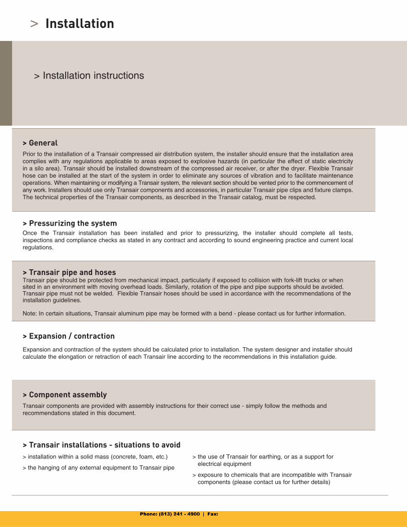
> Installation
Prior to the installation of a Transair compressed air distribution system, the installer should ensure that the installation area complies with any regulations applicable to areas exposed to explosive hazards (in particular the effect of static electricity in a silo area). Transair should be installed downstream of the compressed air receiver, or after the dryer. Flexible Transair hose can be installed at the start of the system in order to eliminate any sources of vibration and to facilitate maintenance operations. When maintaining or modifying a Transair system, the relevant section should be vented prior to the commencement of any work. Installers should use only Transair components and accessories, in particular Transair pipe clips and fixture clamps.The technical properties of the Transair components, as described in the Transair catalog, must be respected.
Once the Transair installation has been installed and prior to pressurizing, the installer should complete all tests,inspections and compliance checks as stated in any contract and according to sound engineering practice and current local regulations.
Transair pipe should be protected from mechanical impact, particularly if exposed to collision with fork-lift trucks or when sited in an environment with moving overhead loads. Similarly, rotation of the pipe and pipe supports should be avoided.Transair pipe must not be welded. Flexible Transair hoses should be used in accordance with the recommendations of the installation guidelines.
Note: In certain situations, Transair aluminum pipe may be formed with a bend - please contact us for further information.
Expansion and contraction of the system should be calculated prior to installation. The system designer and installer shouldcalculate the elongation or retraction of each Transair line according to the recommendations in this installation guide.
Transair components are provided with assembly instructions for their correct use - simply follow the methods andrecommendations stated in this document.
> installation within a solid mass (concrete, foam, etc.)
> the hanging of any external equipment to Transair pipe
> the use of Transair for earthing, or as a support forelectrical equipment
> exposure to chemicals that are incompatible with Transair components (please contact us for further details)
> General
> Pressurizing the system
> Transair pipe and hoses
> Expansion / contraction
> Component assembly
> Transair installations - situations to avoid
> Installation instructions
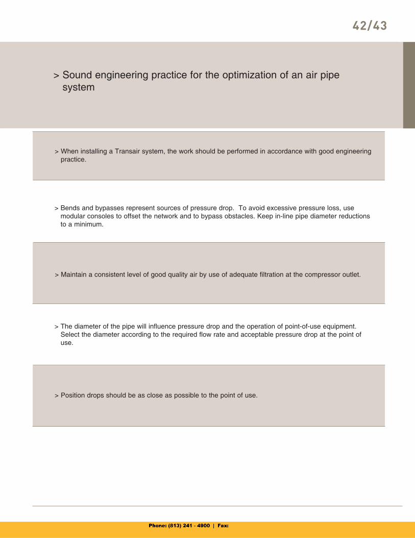
> Bends and bypasses represent sources of pressure drop. To avoid excessive pressure loss, use modular consoles to offset the network and to bypass obstacles. Keep in-line pipe diameter reductionsto a minimum.
> Maintain a consistent level of good quality air by use of adequate filtration at the compressor outlet.
> The diameter of the pipe will influence pressure drop and the operation of point-of-use equipment. Select the diameter according to the required flow rate and acceptable pressure drop at the point of use.
> Position drops should be as close as possible to the point of use.
> Sound engineering practice for the optimization of an air pipesystem
42/43
> When installing a Transair system, the work should be performed in accordance with good engineeringpractice.
>
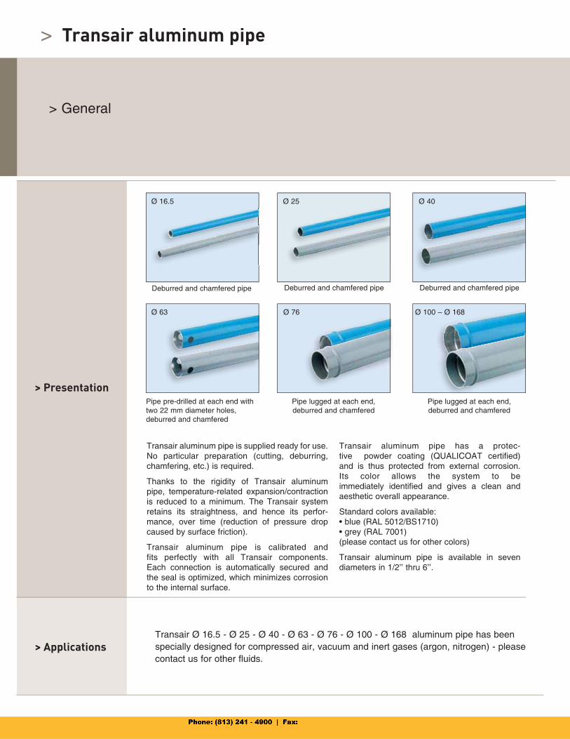
Transair aluminum pipe is supplied ready for use. No particular preparation (cutting, deburring, chamfering, etc.) is required.
Thanks to the rigidity of Transair aluminum pipe, temperature-related expansion/contraction is reduced to a minimum. The Transair system retains its straightness, and hence its perfor-mance, over time (reduction of pressure drop caused by surface friction).
Transair aluminum pipe is calibrated and fits perfectly with all Transair components.Each connection is automatically secured and the seal is optimized, which minimizes corrosion to the internal surface.
Transair aluminum pipe has a protec-tive powder coating (QUALICOAT certified) and is thus protected from external corrosion.Its color allows the system to beimmediately identified and gives a clean and aesthetic overall appearance.
Standard colors available:• blue (RAL 5012/BS1710)• grey (RAL 7001)(please contact us for other colors)
Transair aluminum pipe is available in sevendiameters in 1/2’’ thru 6’’.
Transair aluminum pipe
> Presentation
> ApplicationsTransair Ø 16.5 - Ø 25 - Ø 40 - Ø 63 - Ø 76 - Ø 100 - Ø 168 aluminum pipe has been specially designed for compressed air, vacuum and inert gases (argon, nitrogen) - please contact us for other fluids.
> General
Deburred and chamfered pipe Deburred and chamfered pipe
Pipe pre-drilled at each end with two 22 mm diameter holes,deburred and chamfered
Pipe lugged at each end,deburred and chamfered
Pipe lugged at each end,deburred and chamfered
Deburred and chamfered pipe
Ø 16.5 Ø 25 Ø 40
Ø 63 Ø 76 Ø 100 – Ø 168
44/45
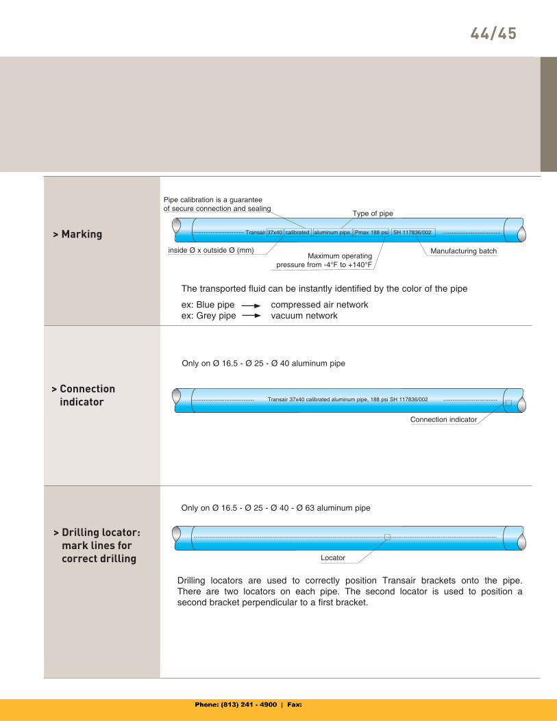
> Connectionindicator
> Drilling locator:mark lines for correct drilling
Only on Ø 16.5 - Ø 25 - Ø 40 aluminum pipe
Drilling locators are used to correctly position Transair brackets onto the pipe. There are two locators on each pipe. The second locator is used to position asecond bracket perpendicular to a first bracket.
> Marking
Only on Ø 16.5 - Ø 25 - Ø 40 - Ø 63 aluminum pipe
The transported fluid can be instantly identified by the color of the pipe
ex: Blue pipe compressed air networkex: Grey pipe vacuum network
Connection indicator
Transair 37x40 calibrated aluminum pipe, 188 psi SH 117836/002
Locator
Pipe calibration is a guarantee of secure connection and sealing
Transair 37x40 calibrated aluminum pipe, Pmax 188 psi SH 117836/002
inside Ø x outside Ø (mm)
Type of pipe
Maximum operatingpressure from -4°F to +140°F
Manufacturing batch
>
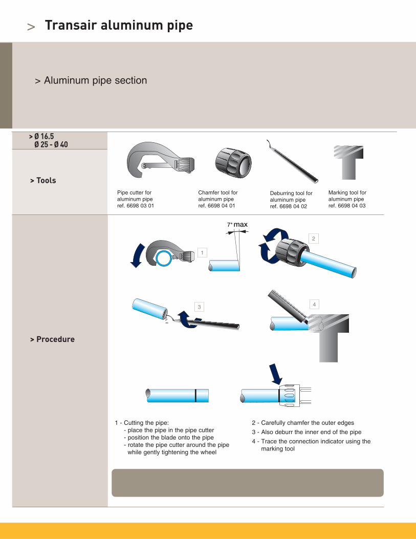
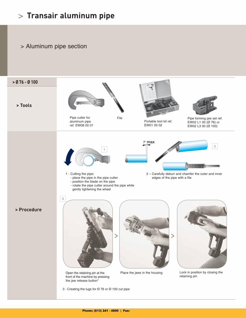
> Aluminum pipe section
> Ø 16.5 Ø 25 - Ø 40
> Procedure
1 - Cutting the pipe:- place the pipe in the pipe cutter- position the blade onto the pipe- rotate the pipe cutter around the pipe while gently tightening the wheel
2 - Carefully chamfer the outer edges
3 - Also deburr the inner end of the pipe
4 - Trace the connection indicator using the marking tool
> ToolsPipe cutter foraluminum piperef. 6698 03 01
Deburring tool for aluminum piperef. 6698 04 02
Chamfer tool foraluminum piperef. 6698 04 01
Marking tool foraluminum piperef. 6698 04 03
The insertion lengths for Ø 16.5 - Ø 25 - Ø 40 connectors are 25 mm, 27 mm and 45 mm respectively,with the exception of the end cap, ref. 6625, for which the insertion lengths are of 39 mm, 42 mm and 64 mm respectively.
Transair aluminum pipe
1
2
3 4
46/47
> Tools
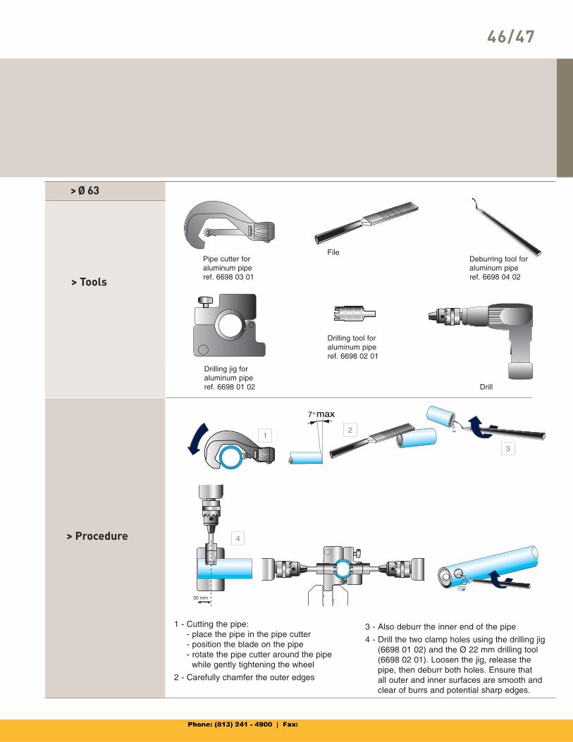
> Procedure
1 - Cutting the pipe:- place the pipe in the pipe cutter- position the blade on the pipe- rotate the pipe cutter around the pipe while gently tightening the wheel
2 - Carefully chamfer the outer edges
3 - Also deburr the inner end of the pipe
4 - Drill the two clamp holes using the drilling jig (6698 01 02) and the Ø 22 mm drilling tool (6698 02 01). Loosen the jig, release the pipe, then deburr both holes. Ensure that all outer and inner surfaces are smooth and clear of burrs and potential sharp edges.
> Ø 63
Pipe cutter foraluminum piperef. 6698 03 01
Deburring tool for aluminum piperef. 6698 04 02
File
Drilling jig foraluminum piperef. 6698 01 02 Drill
Drilling tool foraluminum piperef. 6698 02 01
4
3
21
>
> Aluminum pipe section
1 - Cutting the pipe:- place the pipe in the pipe cutter- position the blade on the pipe- rotate the pipe cutter around the pipe while gently tightening the wheel
2 – Carefully deburr and chamfer the outer and inner edges of the pipe with a file
> Ø 76 - Ø 100
> Procedure
> Tools
Pipe cutter foraluminum piperef. EW08 00 01
FilePortable tool kit ref. EW01 00 02
Pipe forming jaw set ref. EW02 L1 00 (Ø 76) or EW02 L3 00 (Ø 100)
Open the retaining pin at the front of the machine by pressing the jaw release button*
Place the jaws in the housing Lock in position by closing the retaining pin
*
3 - Creating the lugs for Ø 76 or Ø 100 cut pipe
Transair aluminum pipe
Pipe forming jaw set re
12
3
> >
46/47
48/49
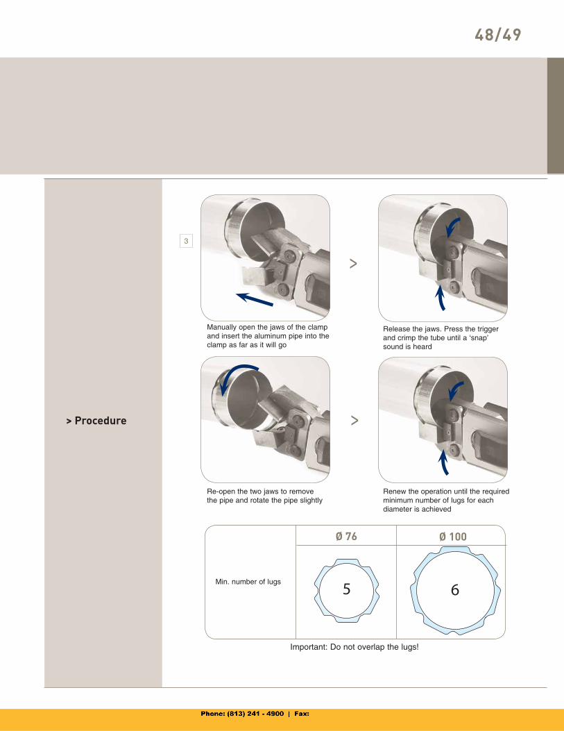
> Procedure
Manually open the jaws of the clamp and insert the aluminum pipe into the clamp as far as it will go
Release the jaws. Press the trigger and crimp the tube until a ‘snap’ sound is heard
Re-open the two jaws to remove the pipe and rotate the pipe slightly
Renew the operation until the required minimum number of lugs for eachdiameter is achieved
Min. number of lugs
Important: Do not overlap the lugs!
Ø 76 Ø 100
3
>
>
5 6
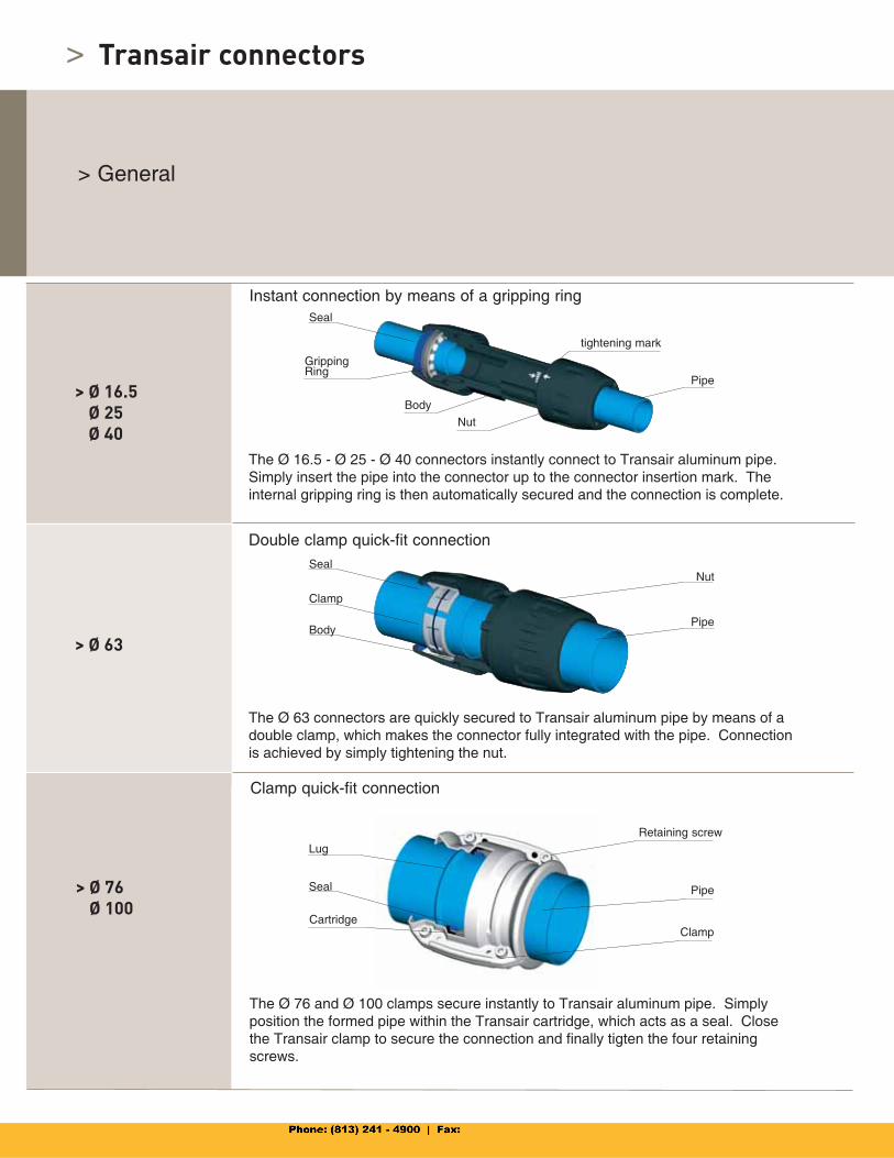
> Transair connectors
> General
> Ø 16.5Ø 25Ø 40
> Ø 63
> Ø 76Ø 100
Instant connection by means of a gripping ring
Double clamp quick-fit connection
Clamp quick-fit connection
Lug
Seal
Cartridge
Retaining screw
Pipe
Clamp
Seal
Clamp
Body
Nut
Pipe
Seal
GrippingRing
Body
Nut
Pipe
tightening mark
The Ø 16.5 - Ø 25 - Ø 40 connectors instantly connect to Transair aluminum pipe. Simply insert the pipe into the connector up to the connector insertion mark. The internal gripping ring is then automatically secured and the connection is complete.
The Ø 63 connectors are quickly secured to Transair aluminum pipe by means of a double clamp, which makes the connector fully integrated with the pipe. Connection is achieved by simply tightening the nut.
The Ø 76 and Ø 100 clamps secure instantly to Transair aluminum pipe. Simply position the formed pipe within the Transair cartridge, which acts as a seal. Close the Transair clamp to secure the connection and finally tigten the four retaining screws.
50/51
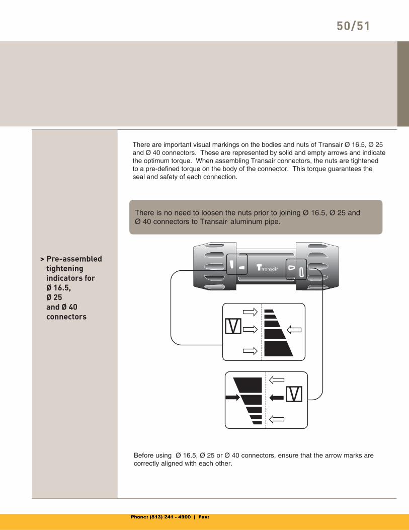
> Pre-assembled tighteningindicators for Ø 16.5,Ø 25and Ø 40connectors
Before using Ø 16.5, Ø 25 or Ø 40 connectors, ensure that the arrow marks are correctly aligned with each other.
There are important visual markings on the bodies and nuts of Transair Ø 16.5, Ø 25 and Ø 40 connectors. These are represented by solid and empty arrows and indicate the optimum torque. When assembling Transair connectors, the nuts are tightened to a pre-defined torque on the body of the connector. This torque guarantees the seal and safety of each connection.
There is no need to loosen the nuts prior to joining Ø 16.5, Ø 25 and Ø 40 connectors to Transair. aluminum pipe.
> Transair connectors
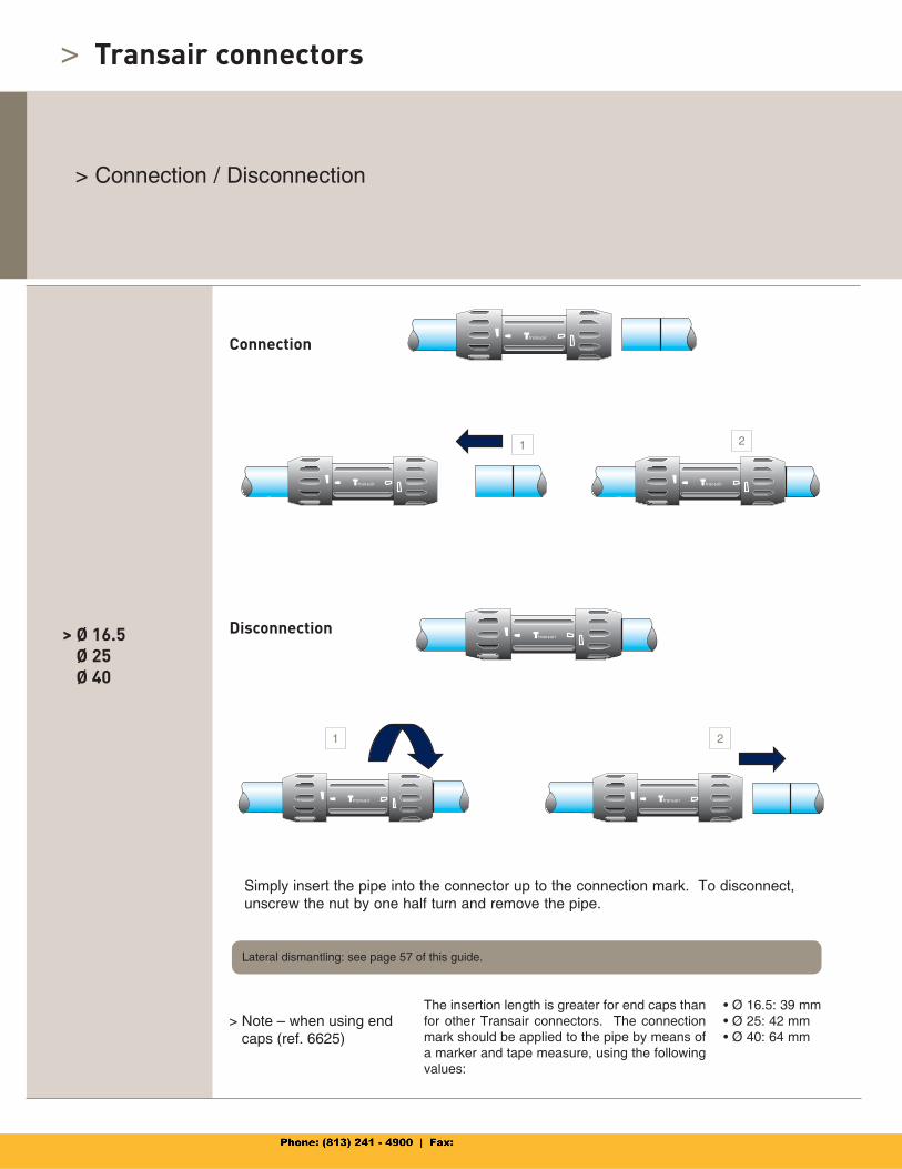
> Connection / Disconnection
Simply insert the pipe into the connector up to the connection mark. To disconnect, unscrew the nut by one half turn and remove the pipe.
> Ø 16.5Ø 25Ø 40
> Note – when using end caps (ref. 6625)
The insertion length is greater for end caps than for other Transair connectors. The connection mark should be applied to the pipe by means of a marker and tape measure, using the following values:
• Ø 16.5: 39 mm• Ø 25: 42 mm• Ø 40: 64 mm
Connection
Disconnection
Lateral dismantling: see page 57 of this guide.
1 2
1 2
52/53
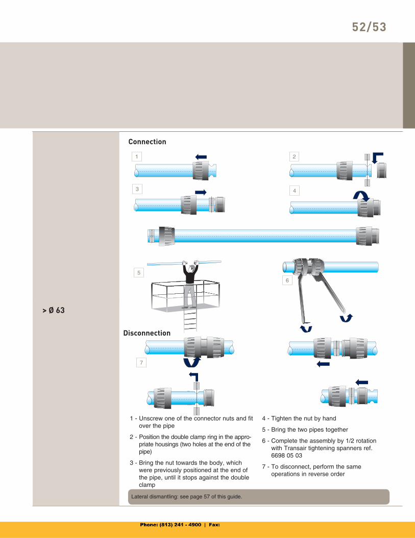
> Ø 63
1 - Unscrew one of the connector nuts and fit over the pipe
2 - Position the double clamp ring in the appro-priate housings (two holes at the end of the pipe)
3 - Bring the nut towards the body, which were previously positioned at the end of the pipe, until it stops against the double clamp
4 - Tighten the nut by hand
5 - Bring the two pipes together
6 - Complete the assembly by 1/2 rotation with Transair tightening spanners ref. 6698 05 03
7 - To disconnect, perform the same operations in reverse order
Connection
Disconnection
Lateral dismantling: see page 57 of this guide.
1 2
3 4
56
7
> Transair connectors
> Connection / Disconnection
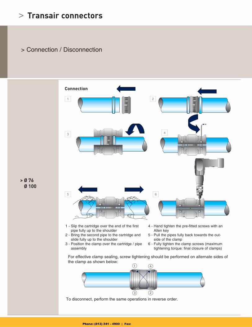
> Ø 76Ø 100
1 - Slip the cartridge over the end of the first pipe fully up to the shoulder
2 - Bring the second pipe to the cartridge and slide fully up to the shoulder
3 - Position the clamp over the cartridge / pipe assembly
4 - Hand tighten the pre-fitted screws with an Allen key
5 - Pull the pipes fully back towards the out-side of the clamp
6 - Fully tighten the clamp screws (maximum tightening torque: final closure of clamps)
Connection
For effective clamp sealing, screw tightening should be performed on alternate sides of the clamp as shown below:
To disconnect, perform the same operations in reverse order.
1
1 2
3 4
5 6
4
3 2
54/55
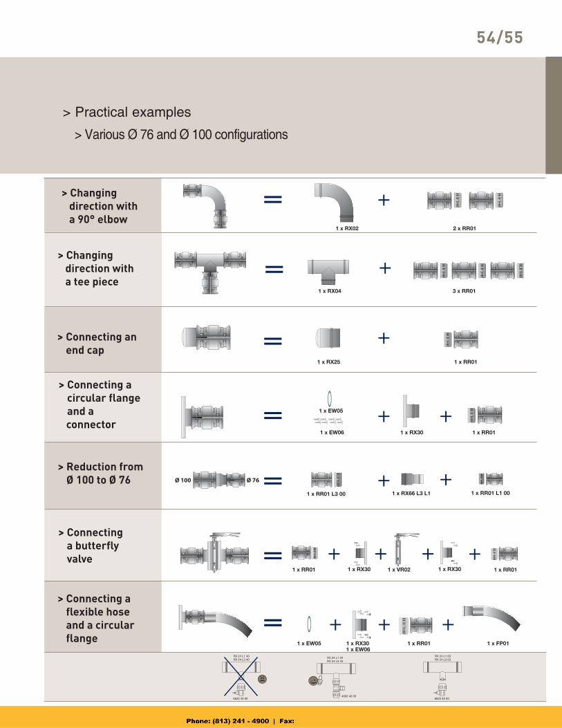
> Practical examples
> Changing direction with a 90° elbow
> Various Ø 76 and Ø 100 configurations
> Changing direction with a tee piece
> Connecting anend cap
> Connecting acircular flangeand a
connector
> Reduction fromØ 100 to Ø 76
> Connectinga butterfly valve
> Connecting a flexible hose and a circular flange
Ø 76 Ø 100
> Transair connectors
> Practical examples
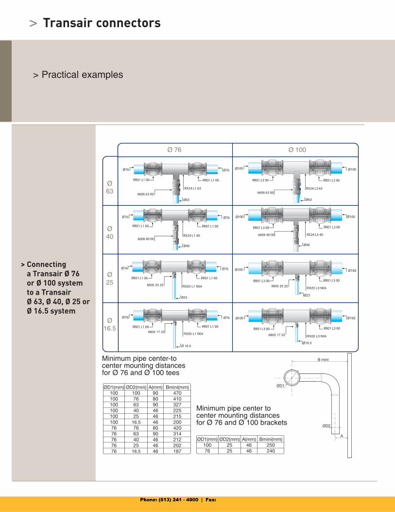
> Connectinga Transair Ø 76 or Ø 100 system to a TransairØ 63, Ø 40, Ø 25 orØ 16.5 system
Minimum pipe center-tocenter mounting distancesfor Ø 76 and Ø 100 tees
Minimum pipe center tocenter mounting distancesfor Ø 76 and Ø 100 brackets
Ø63
Ø40
Ø25
Ø16.5
Ø 76 Ø 100
16.5
16.5
6605 25 22 RX20 L1 N04 6605 25 22RX20 L3 N04
RX20 L3 N04
16.5
6605 17 226605 17 22RX20 L1 N04
16.5
56/57
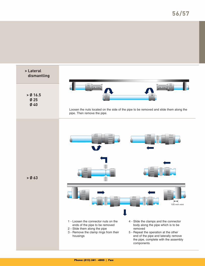
> Ø 16.5Ø 25Ø 40
Loosen the nuts located on the side of the pipe to be removed and slide them along the pipe. Then remove the pipe.
> Ø 63
1 - Loosen the connector nuts on the ends of the pipe to be removed
2 - Slide them along the pipe3 - Remove the clamp rings from their housings
4 - Slide the clamps and the connector body along the pipe which is to be removed
5 - Repeat the operation at the other end of the pipe and laterally remove the pipe, complete with the assembly components
> Lateraldismantling
>
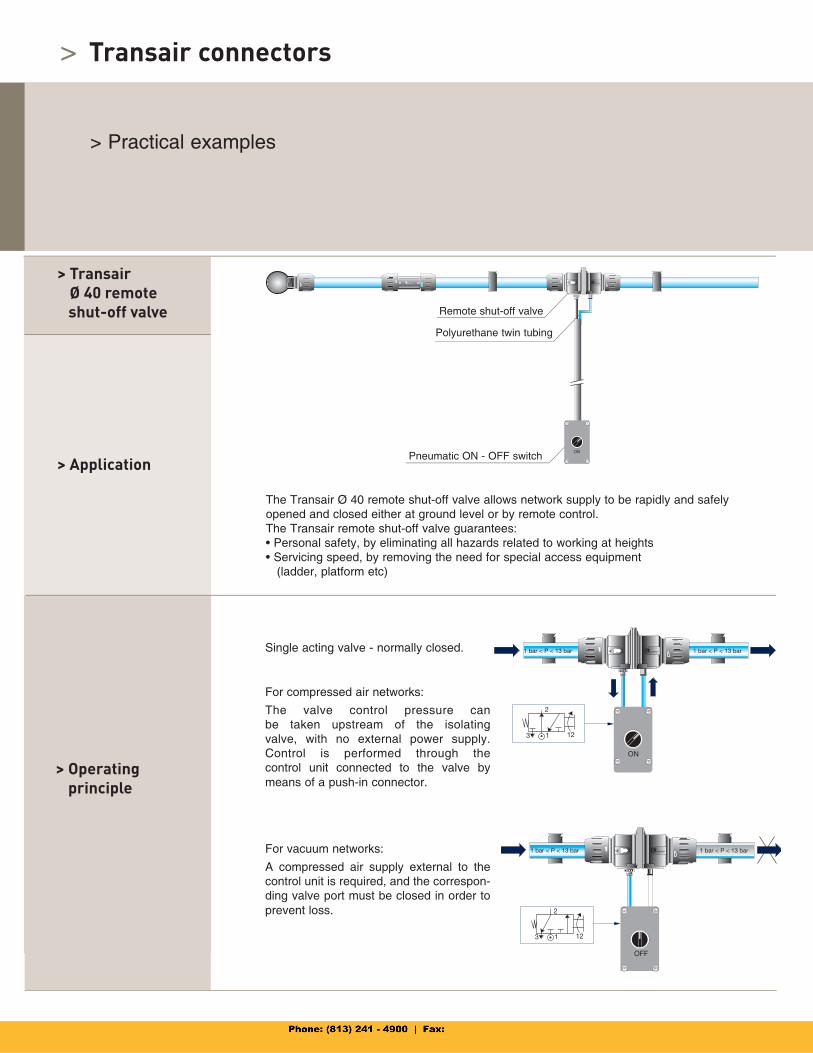
> Application
The Transair Ø 40 remote shut-off valve allows network supply to be rapidly and safely opened and closed either at ground level or by remote control. The Transair remote shut-off valve guarantees: • Personal safety, by eliminating all hazards related to working at heights • Servicing speed, by removing the need for special access equipment (ladder, platform etc)
> Operatingprinciple
Single acting valve - normally closed.
For compressed air networks:
The valve control pressure can be taken upstream of the isolatingvalve, with no external power supply.Control is performed through thecontrol unit connected to the valve by means of a push-in connector.
For vacuum networks:
A compressed air supply external to the control unit is required, and the correspon-ding valve port must be closed in order to prevent loss.
> TransairØ 40 remote
shut-off valve Remote shut-off valve
Pneumatic ON - OFF switch
Polyurethane twin tubing
Transair connectors
> Practical examples
58/59
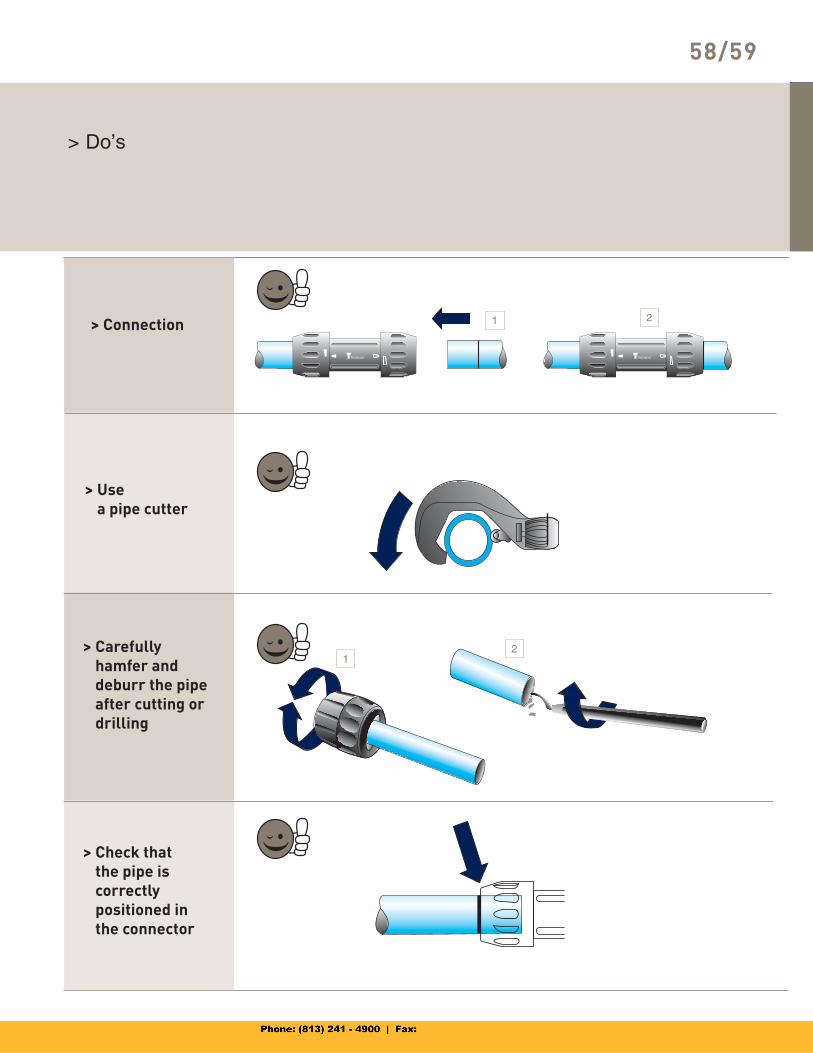
> Do’s
> Connection
> Carefully hamfer and deburr the pipe after cutting or drilling
> Usea pipe cutter
> Check thatthe pipe iscorrectlypositioned in the connector
1
1
2
2
>
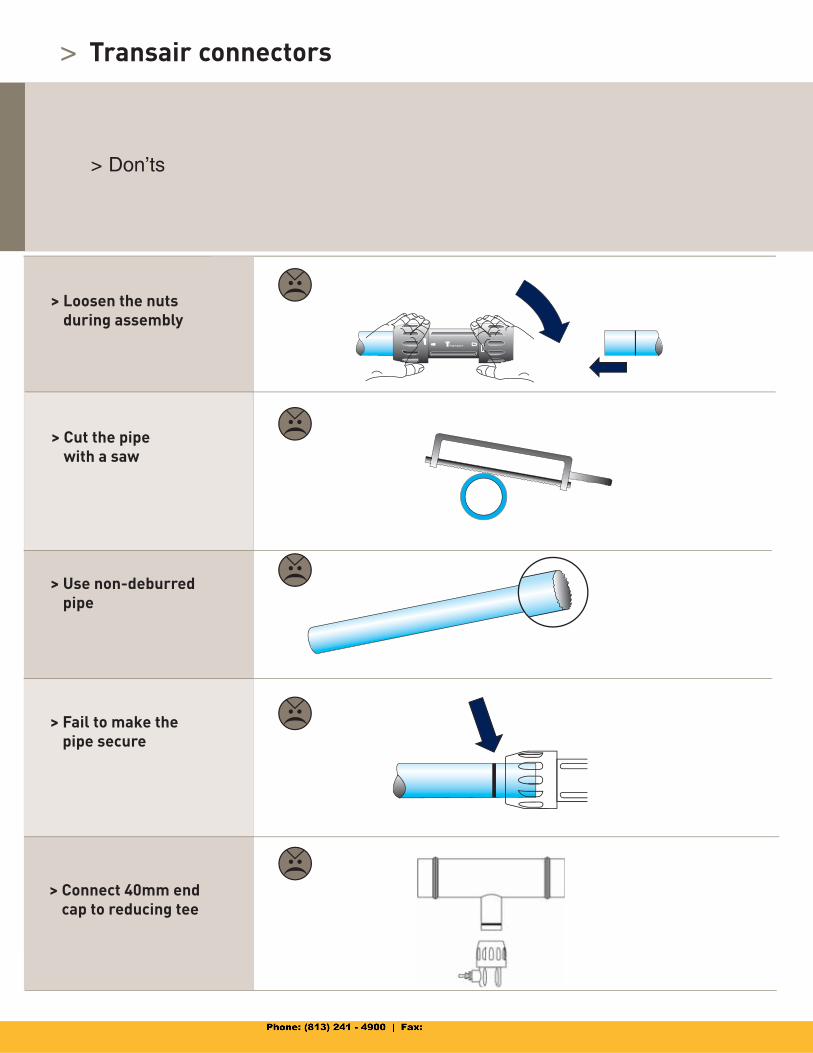
> Don’ts
> Loosen the nutsduring assembly
> Cut the pipewith a saw
> Use non-deburredpipe
> Fail to make thepipe secure
> Connect 40mm end cap to reducing tee
Transair connectors
>
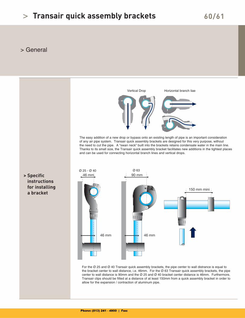
> General
> Specificinstructionsfor installing a bracket
Ø 25 - Ø 40 Ø 63
Vertical Drop Horizontal branch liae
For the Ø 25 and Ø 40 Transair quick assembly brackets, the pipe center to wall distrance is equal to the bracket center to wall distance, i.e. 46mm. For the Ø 63 Transair quick assembly brackets, the pipe center to wall distance is 90mm and the Ø 25 and Ø 40 bracket center distance is 46mm. Furthermore, Transair clips should be fitted at a distance of at least 150mm from a quick assembly bracket in order to allow for the expansion / contraction of aluminum pipe.
60/61Transair quick assembly brackets
The easy addition of a new drop or bypass onto an existing length of pipe is an important consideration of any air pipe system. Transair quick assembly brackets are designed for this very purpose, without the need to cut the pipe. A “swan neck” built into the brackets retains condensate water in the main line. Thanks to its small size, the Transair quick assembly bracket facilitates new additions in the tightest places and can be used for connecting horizontal branch lines and vertical drops.
>
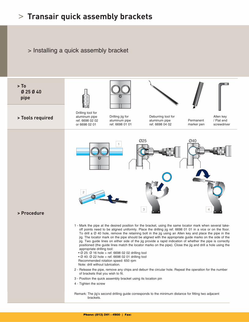
> Installing a quick assembly bracket
> Tools required
> Procedure
1 - Mark the pipe at the desired position for the bracket, using the same locator mark when several take-off points need to be aligned uniformly. Place the drilling jig ref. 6698 01 01 in a vice or on the floor.To drill a Ø 40 hole, remove the retaining bolt in the jig using an Allen key and place the pipe in the jig. The locator mark on the pipe should be aligned with the appropriate guide marks on the side of the jig. Two guide lines on either side of the jig provide a rapid indication of whether the pipe is correctly positioned (the guide lines match the locator marks on the pipe). Close the jig and drill a hole using the appropriate drilling tool:
• Ø 25: Ø 16 hole > ref. 6698 02 02 drilling tool • Ø 40: Ø 22 hole > ref. 6698 02 01 drilling tool Recommended rotation speed: 650 rpm Note: drill without lubrication.
2 - Release the pipe, remove any chips and deburr the circular hole. Repeat the operation for the number of brackets that you wish to fit.
3 - Position the quick assembly bracket using its location pin
4 - Tighten the screw
Remark: The jig’s second drilling guide corresponds to the minimum distance for fitting two adjacent brackets.
> ToØ 25 Ø 40
pipe
Drilling tool foraluminum piperef. 6698 02 02or 6698 02 01
Drilling jig foraluminum piperef. 6698 01 01
Deburring tool for aluminum piperef. 6698 04 02
Permanent marker pen
Allen key / Flat end screwdriver
Transair quick assembly brackets
1
2
3 4
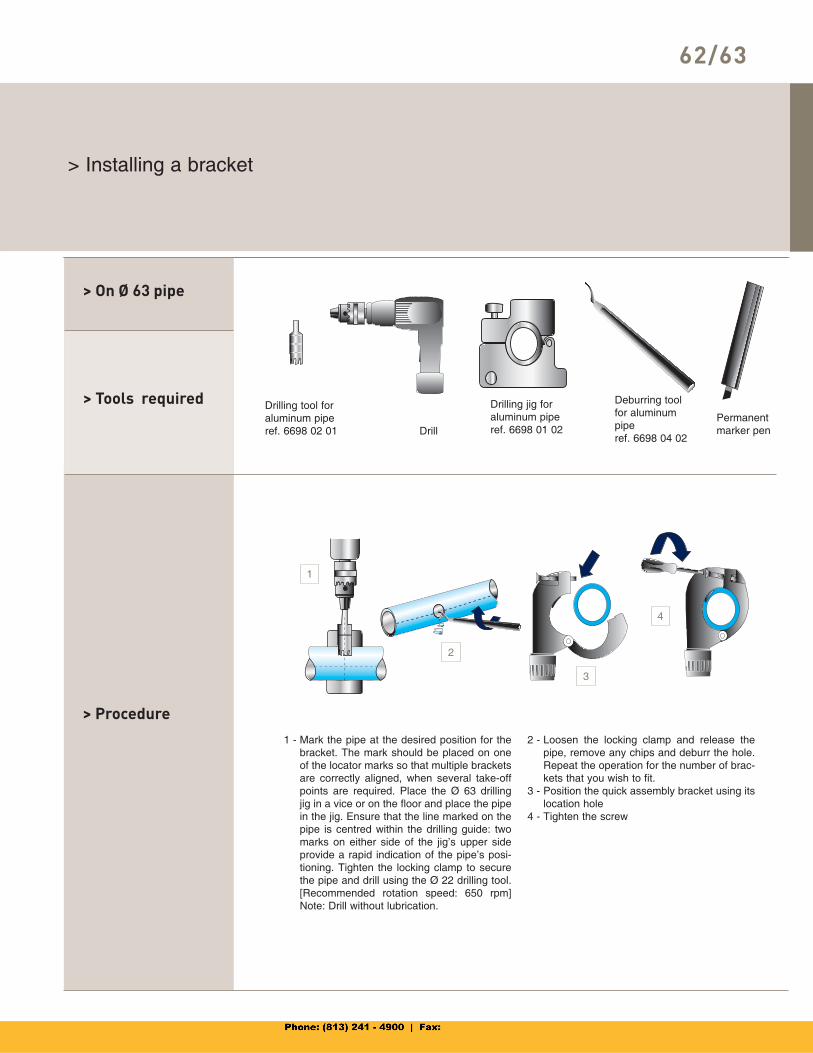
> Installing a bracket
> Tools required
> Procedure1 - Mark the pipe at the desired position for the
bracket. The mark should be placed on one of the locator marks so that multiple brackets are correctly aligned, when several take-off points are required. Place the Ø 63 drilling jig in a vice or on the floor and place the pipe in the jig. Ensure that the line marked on the pipe is centred within the drilling guide: two marks on either side of the jig’s upper side provide a rapid indication of the pipe’s posi-tioning. Tighten the locking clamp to secure the pipe and drill using the Ø 22 drilling tool.[Recommended rotation speed: 650 rpm] Note: Drill without lubrication.
2 - Loosen the locking clamp and release the pipe, remove any chips and deburr the hole. Repeat the operation for the number of brac-kets that you wish to fit.
3 - Position the quick assembly bracket using its location hole
4 - Tighten the screw
> On Ø 63 pipe
Drilling tool foraluminum piperef. 6698 02 01
Drilling jig foraluminum piperef. 6698 01 02
Deburring tool for aluminum piperef. 6698 04 02
Permanent marker penDrill
62/63
1
2
3
4
>
> Installing a bracket
> Tools required
> Procedure
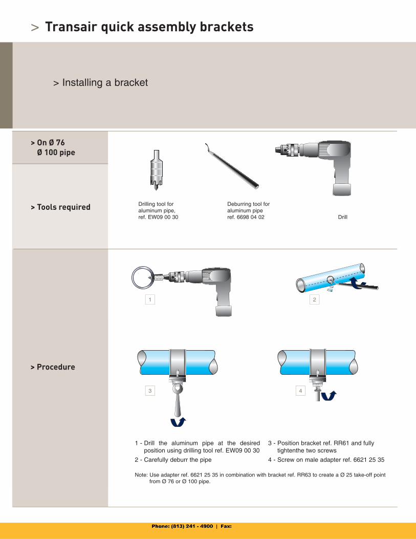
> On Ø 76Ø 100 pipe
Drilling tool foraluminum pipe,ref. EW09 00 30 Drill
1 - Drill the aluminum pipe at the desired position using drilling tool ref. EW09 00 30
2 - Carefully deburr the pipe
3 - Position bracket ref. RR61 and fully tighten the two screws
4 - Screw on male adapter ref. 6621 25 35
Note: Use adapter ref. 6621 25 35 in combination with bracket ref. RR63 to create a Ø 25 take-off point from Ø 76 or Ø 100 pipe.
Deburring tool for aluminum piperef. 6698 04 02
Transair quick assembly brackets
1 2
3 4
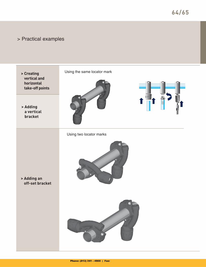
> Practical examples
> Addinga verticalbracket
> Adding anoff-set bracket
> Creatingvertical andhorizontaltake-off points
Using the same locator mark
Using two locator marks
64/65
1 2
>
> Practical Examples
> Tools required
> Procedure
Use the under pressure drilling tool to fit a bracket to an existing pressurised system. This can be simply done with use of a standard drill.
> Installing a bracket to a pressurised system
Drill bit
Threaded connector to screw onto the air intake
Silencer attachment pointTool body
End cap
1 - Position the pressurized system bracket and fully tighten the two screws
2 - Screw the assembly onto the ball valve and ensure that the valve is open
3 - Screw the drilling tool onto the ball valve until complete
4 - Remove the drill and close the ball valveimmediately and dismantle the drilling tool
Transair quick assembly brackets
1
2 3 4
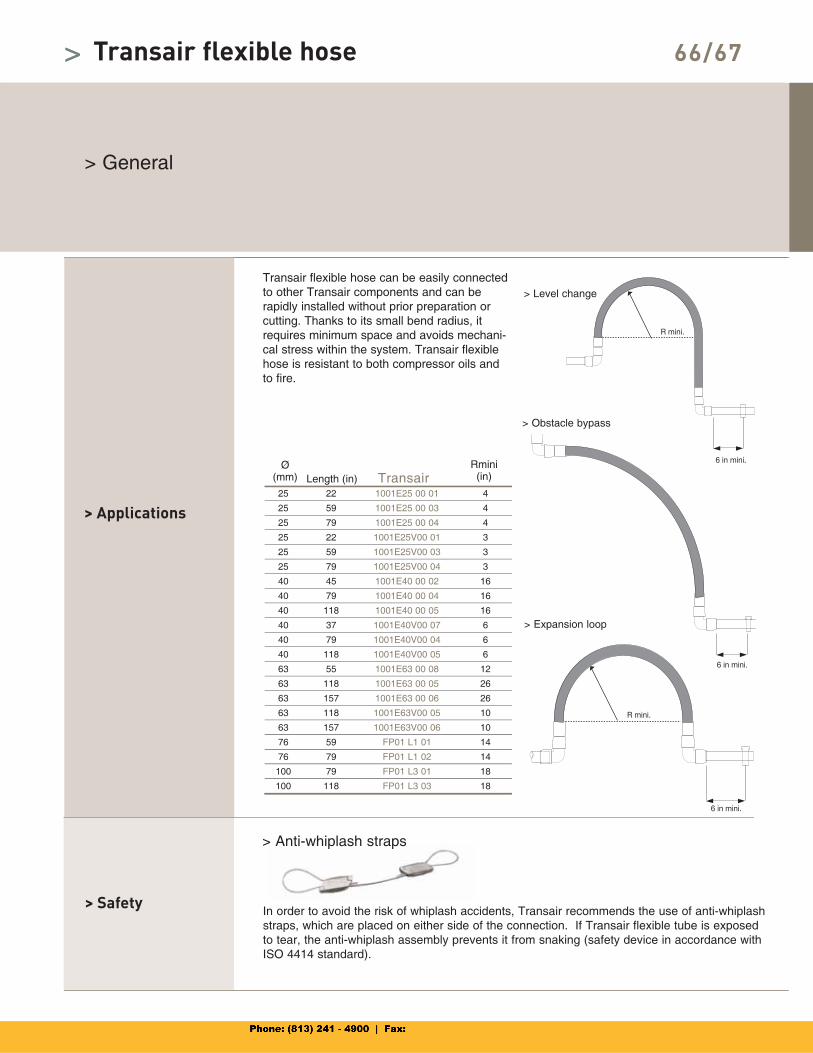
Transair
> Transair flexible hose
> General
> Applications
> Safety
Transair flexible hose can be easily connected to other Transair components and can berapidly installed without prior preparation or cutting. Thanks to its small bend radius, it requires minimum space and avoids mechani-cal stress within the system. Transair flexible hose is resistant to both compressor oils and to fire.
> Anti-whiplash straps
Ø(mm) Length (in)
Rmini(in)
> Level change
> Obstacle bypass
> Expansion loop
In order to avoid the risk of whiplash accidents, Transair recommends the use of anti-whiplash straps, which are placed on either side of the connection. If Transair flexible tube is exposed to tear, the anti-whiplash assembly prevents it from snaking (safety device in accordance with ISO 4414 standard).
66/67>
25 22 1001E25 00 01 4
25 59 1001E25 00 03 4
25 79 1001E25 00 04 4
25 22 1001E25V00 01 3
25 59 1001E25V00 03 3
25 79 1001E25V00 04 3
40 45 1001E40 00 02 16
40 79 1001E40 00 04 16
40 118 1001E40 00 05 16
40 37 1001E40V00 07 6
40 79 1001E40V00 04 6
40 118 1001E40V00 05 6
63 55 1001E63 00 08 12
63 118 1001E63 00 05 26
63 157 1001E63 00 06 26
63 118 1001E63V00 05 10
63 157 1001E63V00 06 10
76 59 FP01 L1 01 14
76 79 FP01 L1 02 14
100 79 FP01 L3 01 18
100 118 FP01 L3 03 18
> Anti whiplash straps
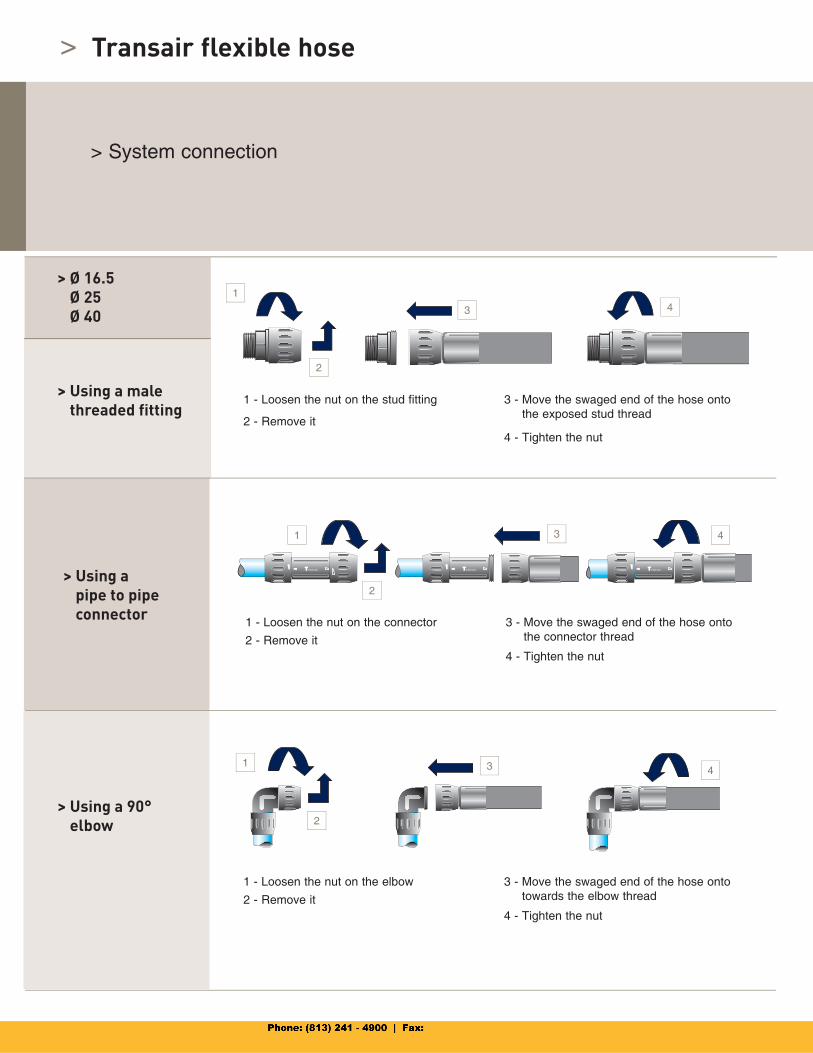
>
1 - Loosen the nut on the stud fitting
2 - Remove it
3 - Move the swaged end of the hose onto the exposed stud thread
4 - Tighten the nut
> Ø 16.5Ø 25Ø 40
> Using a 90°elbow
> System connection
> Using a male threaded fitting
> Using apipe to pipe connector 1 - Loosen the nut on the connector
2 - Remove it
3 - Move the swaged end of the hose onto the connector thread
4 - Tighten the nut
1 - Loosen the nut on the elbow
2 - Remove it
3 - Move the swaged end of the hose onto towards the elbow thread
4 - Tighten the nut
Transair flexible hose
1
3 4
1
2
3 4
1
2
3 4
2
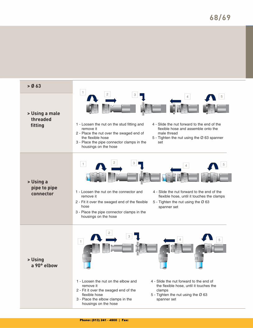
68/69
> Using a malethreaded
fitting
1 - Loosen the nut on the connector and remove it
2 - Fit it over the swaged end of the flexible hose
3 - Place the pipe connector clamps in the housings on the hose
4 - Slide the nut forward to the end of the flexible hose, until it touches the clamps
5 - Tighten the nut using the Ø 63 spanner set
> Using apipe to pipe connector
1 - Loosen the nut on the stud fitting and remove it
2 - Place the nut over the swaged end of the flexible hose
3 - Place the pipe connector clamps in the housings on the hose
4 - Slide the nut forward to the end of the flexible hose and assemble onto the male thread
5 - Tighten the nut using the Ø 63 spanner set
1 - Loosen the nut on the elbow and remove it
2 - Fit it over the swaged end of theflexible hose
3 - Place the elbow clamps in the housings on the hose
4 - Slide the nut forward to the end of the flexible hose, until it touches the clamps
5 - Tighten the nut using the Ø 63spanner set
> Usinga 90° elbow
> Ø 631
2 34 5
1 2 34 5
1
23
4 5
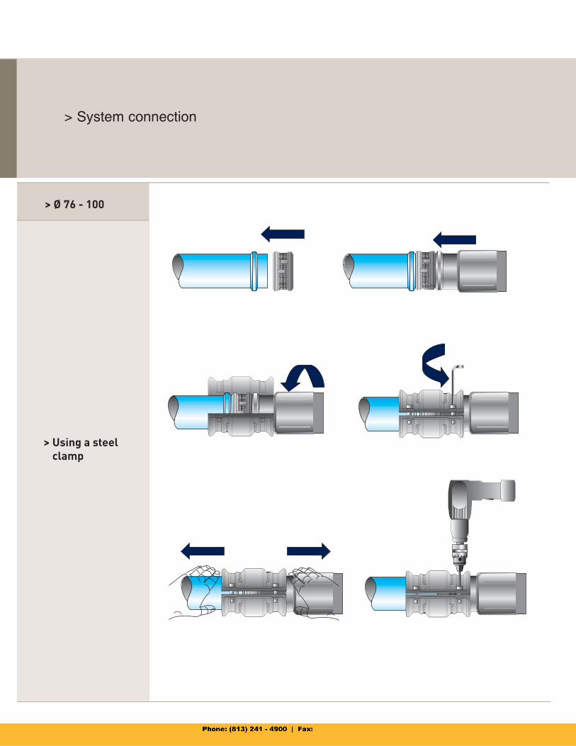
Transair flexible hose> System connection
> Ø 76 - 100
> Using a steelclamp
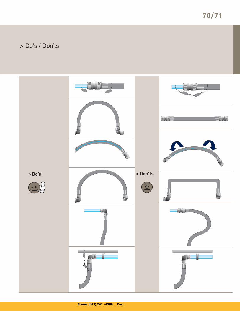
68/69
70/71
> Do’s > Don’ts
> Do’s / Don’ts
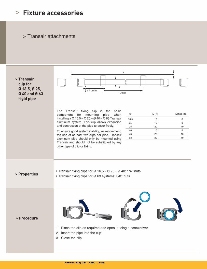
>
The Transair fixing clip is the basiccomponent for mounting pipe wheninstalling a Ø 16.5 – Ø 25 – Ø 40 – Ø 63 Transairaluminum system. This clip allows expansion and contraction of the pipe to occur freely.
To ensure good system stability, we recommend the use of at least two clips per pipe. Transair aluminum pipe should only be mounted using Transair and should not be substituted by any other type of clip or fixing.
Fixture accessories
> Transair attachments
> Transairclip forØ 16.5, Ø 25,Ø 40 and Ø 63rigid pipe
> Procedure
1 - Place the clip as required and open it using a screwdriver
2 - Insert the pipe into the clip
3 - Close the clip
> Properties• Transair fixing clips for Ø 16.5 - Ø 25 - Ø 40: 1/4’’ nuts
• Transair fixing clips for Ø 63 systems: 3/8’’ nuts
Ø L (ft) Dmax (ft)
ø
16.5 10 8
25 10 8
25 20 10
40 10 8
40 20 10
63 20 10
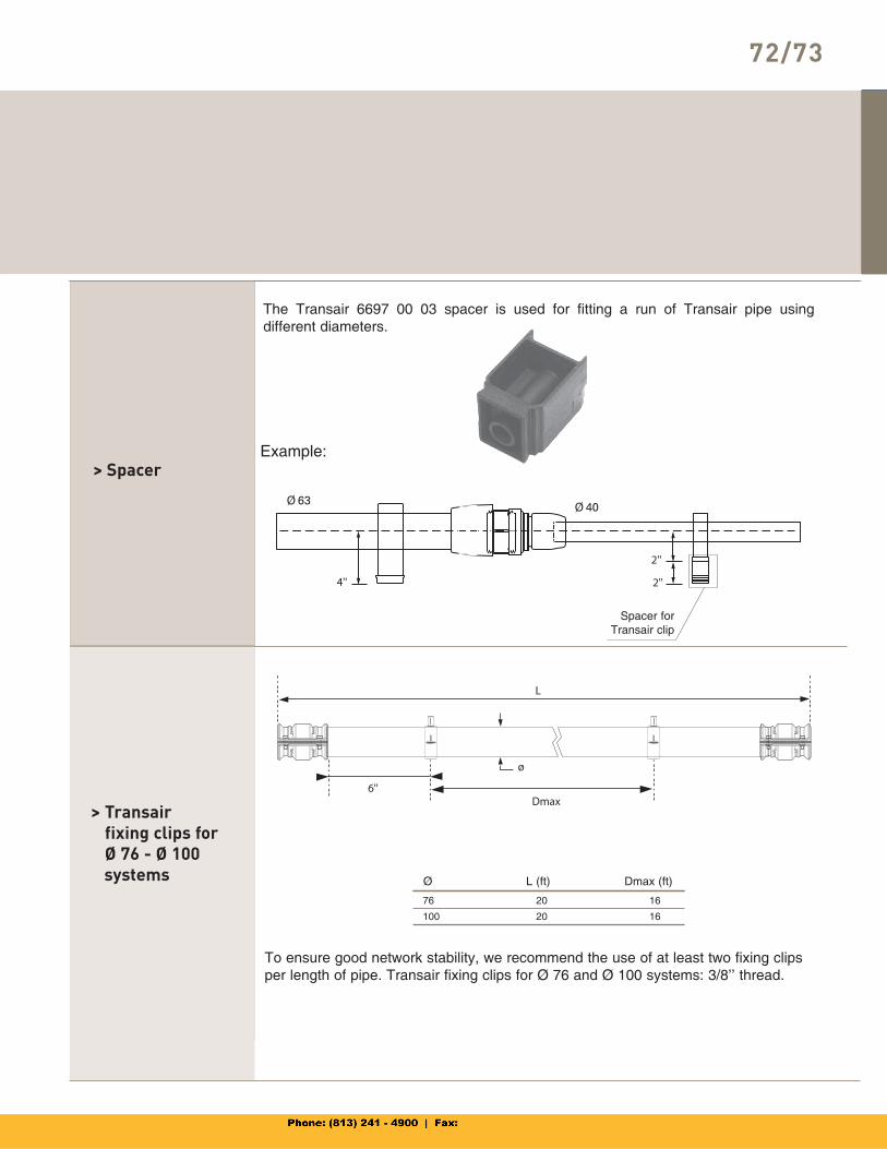
72/73
> Spacer
The Transair 6697 00 03 spacer is used for fitting a run of Transair pipe usingdifferent diameters.
> Transair fixing clips forØ 76 - Ø 100
systems
To ensure good network stability, we recommend the use of at least two fixing clips per length of pipe. Transair fixing clips for Ø 76 and Ø 100 systems: 3/8’’ thread.
Example:
Spacer for Transair clip
76 20 16
100 20 16
Ø L (ft) Dmax (ft)
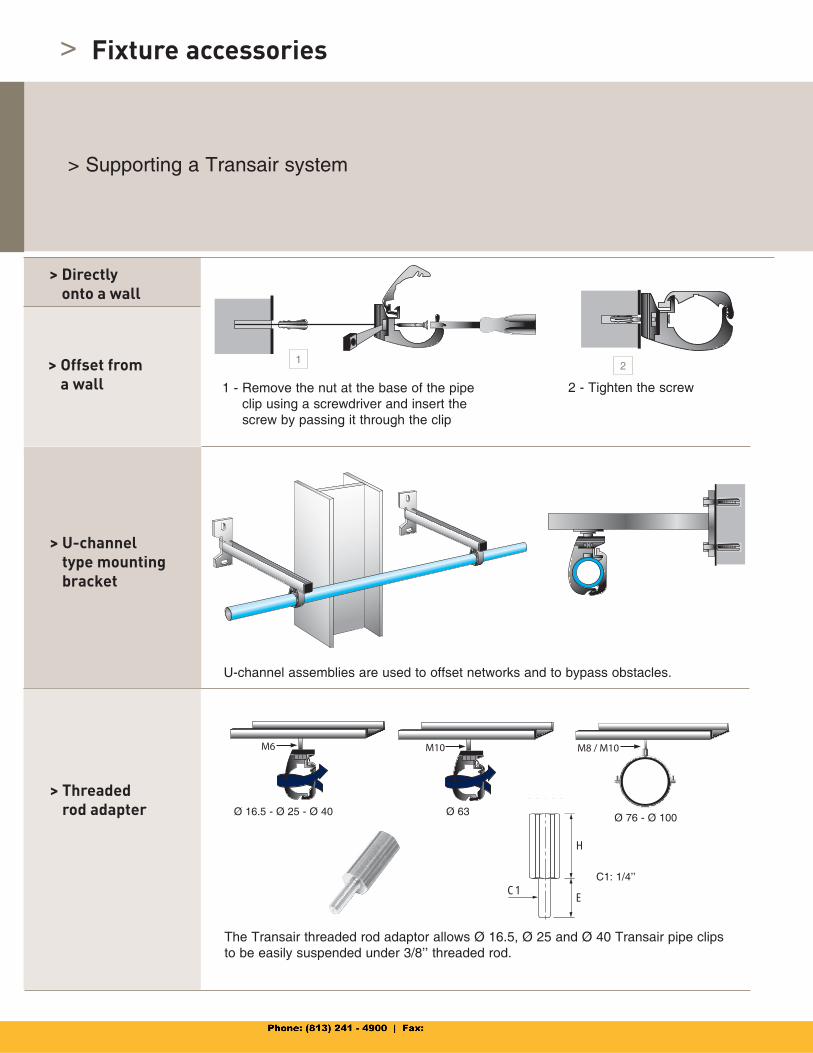
> Fixture accessories
> Supporting a Transair system
> Offset froma wall 1 - Remove the nut at the base of the pipe
clip using a screwdriver and insert the screw by passing it through the clip
> U-channeltype mounting bracket
U-channel assemblies are used to offset networks and to bypass obstacles.
> Directlyonto a wall
> Threadedrod adapter
The Transair threaded rod adaptor allows Ø 16.5, Ø 25 and Ø 40 Transair pipe clips to be easily suspended under 3/8’’ threaded rod.
Ø 16.5 - Ø 25 - Ø 40 Ø 63Ø 76 - Ø 100
C1: 1/4’’
2 - Tighten the screw
H
C1E
12
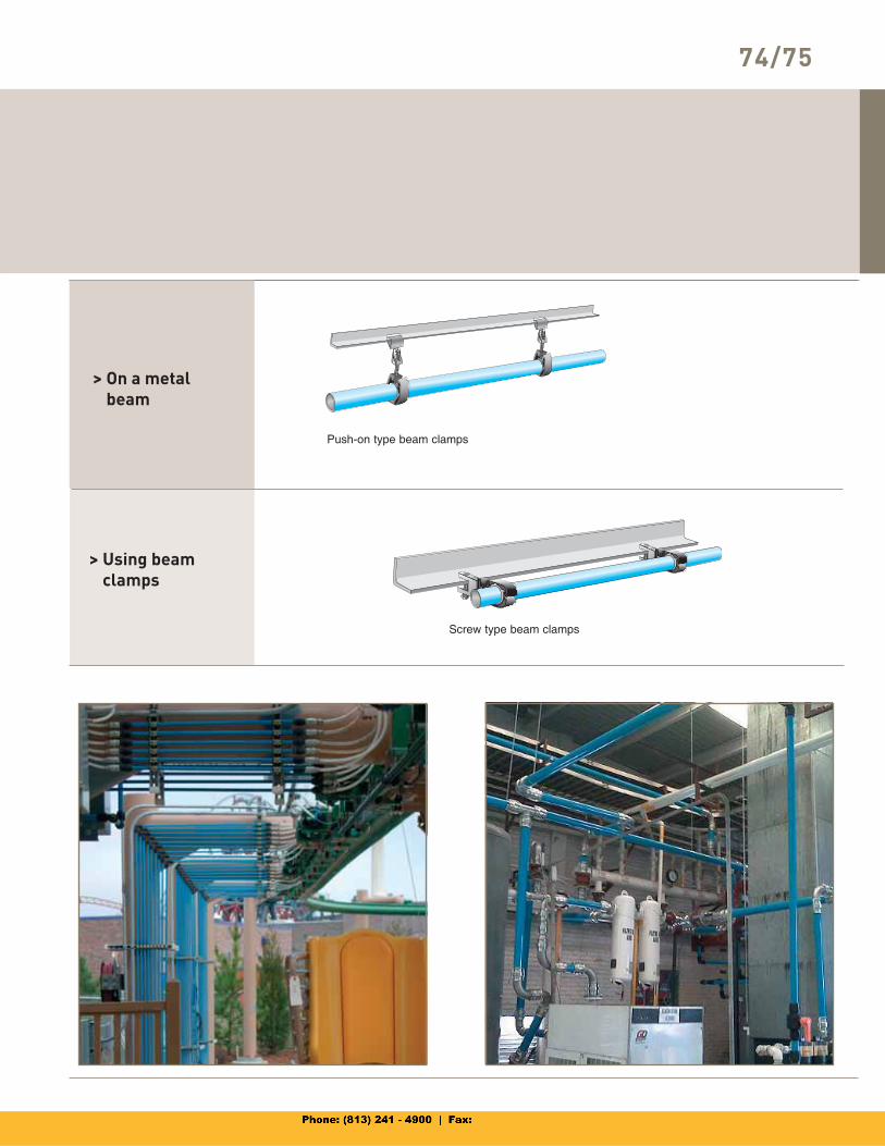
74/75
> Using beamclamps
> On a metalbeam
Push-on type beam clamps
Screw type beam clamps
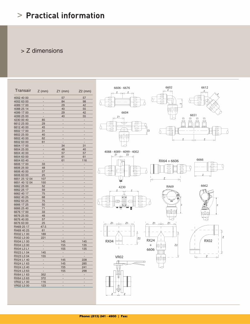
Transair
> Practical information
> Z dimensions
Z (mm) Z1 (mm) Z2 (mm)
6666
Z
4088 - 4089 - 4099 - 4002Z1 Z2
4230Z Z
6651
Z Z
6602Z
Z
6606 - 6676Z Z
6612Z
Z
6604Z1
Z2
RA69
Z
6662
RX04Z2
Z1 Z1
RX24+
6606
Z1 Z1
Z2
RX02
Z
Z
RX64 + 6606
Z
VR02
Z Z
4002 40 00 - 57 574002 63 00 - 84 984089 17 00 - 29 424088 25 14 - 40 554099 17 00 - 29 424099 25 00 - 40 554230 00 40 85 - -6612 25 00 29 - -6612 40 00 45 - -6602 17 00 31 - -6602 25 00 40 - -6602 40 00 62 - -6602 63 00 61 - -6604 17 00 - 34 316604 25 00 - 48 406604 40 00 - 57 576604 63 00 - 61 616604 63 40 - 61 1166606 17 00 33 - -6606 25 00 48 - -6606 40 00 57 - -6606 63 00 25 - -6651 25 12 04 107 - -6651 40 12 04 150 - -6662 25 00 52 - -6662 25 17 59 - -6662 40 17 75 - -6662 40 25 68 - -6662 63 25 75 - -6666 17 25 50 - -6666 25 40 71 - -6676 17 00 33 - -6676 25 00 48 - -6676 40 00 57 - -6676 63 00 25 - -RA69 25 17 47.5 - -RA69 40 25 61 - -RX02 L1 00 189 - -RX02 L3 00 221 - -RX04 L1 00 - 145 145RX04 L3 00 - 155 135RX04 L3 L1 - 155 135RX23 L1 04 145 - -RX23 L3 04 155 - -RX24 L1 40 - 145 228RX24 L1 63 - 145 285RX24 L3 40 - 155 241RX24 L3 63 - 155 298RX64 L1 63 352 - -RX64 L3 63 372 - -VR02 L1 00 116 - -VR02 L3 00 123 - -
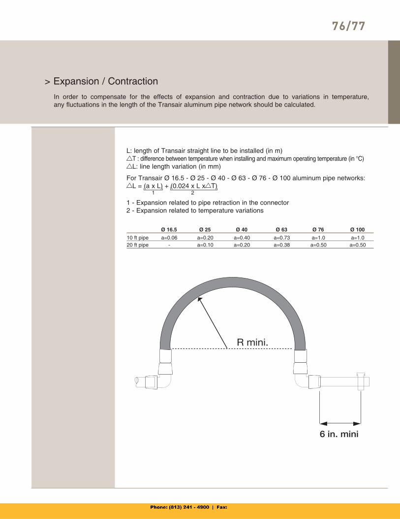
76/77
> Expansion / Contraction
L: length of Transair straight line to be installed (in m) T : difference between temperature when installing and maximum operating temperature (in °C) L: line length variation (in mm)
For Transair Ø 16.5 - Ø 25 - Ø 40 - Ø 63 - Ø 76 - Ø 100 aluminum pipe networks: L = (a x L) + (0.024 x L x T)
In order to compensate for the effects of expansion and contraction due to variations in temperature,any fluctuations in the length of the Transair aluminum pipe network should be calculated.
1 2
1 - Expansion related to pipe retraction in the connector 2 - Expansion related to temperature variations
10 ft pipe a=0.06 a=0.20 a=0.40 a=0.73 a=1.0 a=1.020 ft pipe - a=0.10 a=0.20 a=0.38 a=0.50 a=0.50
Ø 16.5 Ø 25 Ø 40 Ø 63 Ø 76 Ø 100
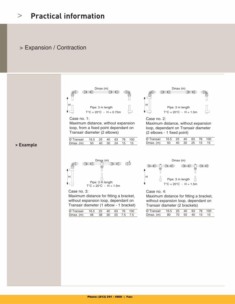
>
> Expansion / Contraction
Case no. 1:Maximum distance, without expansion loop, from a fixed point dependant on Transair diameter (2 elbows)
Case no. 2:Maximum distance, without expansion loop, dependant on Transair diameter(2 elbows - 1 fixed point)
Fixed point
Ø Transair 16.5 25 40 63 76 100Dmax. (m) 50 40 30 24 15 15
Ø Transair 16.5 25 40 63 76 100Dmax. (m) 50 40 30 25 15 15
Practical information
Case no. 4:Maximum distance for fitting a bracket, without expansion loop, dependant on Transair diameter (2 brackets)
Ø Transair 16.5 25 40 63 76 100Dmax. (m) 48 38 30 25 7.5 7.5
Ø Transair 16.5 25 40 63 76 100Dmax. (m) 80 70 55 40 15 15
Case no. 3:Maximum distance for fitting a bracket, without expansion loop, dependant on Transair diameter (1 elbow - 1 bracket)
> Example
T°C = 20°C - H = 0.75m T°C = 20°C - H = 1.5m
T°C = 20°C - H = 1.5m T°C = 20°C - H = 1.5m
H
Dmax (m)
H
Dmax (m)
Dmax (m) Dmax (m)
HH
Pipe: 3 m lengthPipe: 3 m length
Pipe: 3 m lengthPipe: 3 m length
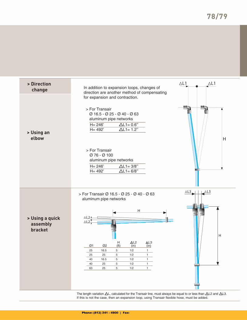
78/79
In addition to expansion loops, changes of direction are another method of compensating for expansion and contraction.
> Using anelbow
> Using a quick assemblybracket
> For TransairØ 16.5 - Ø 25 - Ø 40 - Ø 63aluminum pipe networks
> For TransairØ 76 - Ø 100aluminum pipe networks
Ø1 Ø2H(ft)
L2(in)
L3 (in)
The length variation L, calculated for the Transair line, must always be equal to or less than L2 and L3.If this is not the case, then an expansion loop, using Transair flexible hose, must be added.
> For Transair Ø 16.5 - Ø 25 - Ø 40 - Ø 63aluminum pipe networks
> Direction change
H= 246’ L1= 0.6’’H= 492’ L1= 1.2’’
25 16.5 5 1/2 1
25 25 5 1/2 1
40 16.5 5 1/2 1
40 25 5 1/2 1
63 25 5 1/2 1
H= 246’ L1= 3/8’’H= 492’ L1= 6/8’’
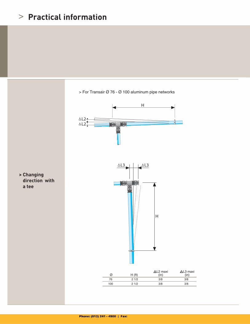
>
> Changingdirection with a tee
> For Transair Ø 76 - Ø 100 aluminum pipe networks
L2 maxi (in)
L3 maxi(in)H (ft)Ø
Practical information
76 2 1/2 3/8 3/8
100 2 1/2 3/8 3/8
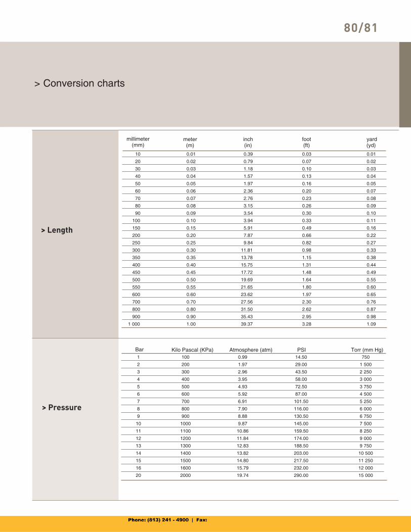
80/81
> Conversion charts
> Length
> Pressure
1 100 0.99 14.50 750
2 200 1.97 29.00 1 500
3 300 2.96 43.50 2 250
4 400 3.95 58.00 3 000
5 500 4.93 72.50 3 750
6 600 5.92 87.00 4 500
7 700 6.91 101.50 5 250
8 800 7.90 116.00 6 000
9 900 8.88 130.50 6 750
10 1000 9.87 145.00 7 500
11 1100 10.86 159.50 8 250
12 1200 11.84 174.00 9 000
13 1300 12.83 188.50 9 750
14 1400 13.82 203.00 10 500
15 1500 14.80 217.50 11 250
16 1600 15.79 232.00 12 000
20 2000 19.74 290.00 15 000
Bar Kilo Pascal (KPa) Atmosphere (atm) PSI Torr (mm Hg)
10 0.01 0.39 0.03 0.01
20 0.02 0.79 0.07 0.02
30 0.03 1.18 0.10 0.03
40 0.04 1.57 0.13 0.04
50 0.05 1.97 0.16 0.05
60 0.06 2.36 0.20 0.07
70 0.07 2.76 0.23 0.08
80 0.08 3.15 0.26 0.09
90 0.09 3.54 0.30 0.10
100 0.10 3.94 0.33 0.11
150 0.15 5.91 0.49 0.16
200 0.20 7.87 0.66 0.22
250 0.25 9.84 0.82 0.27
300 0.30 11.81 0.98 0.33
350 0.35 13.78 1.15 0.38
400 0.40 15.75 1.31 0.44
450 0.45 17.72 1.48 0.49
500 0.50 19.69 1.64 0.55
550 0.55 21.65 1.80 0.60
600 0.60 23.62 1.97 0.65
700 0.70 27.56 2.30 0.76
800 0.80 31.50 2.62 0.87
900 0.90 35.43 2.95 0.98
1 000 1.00 39.37 3.28 1.09
millimeter(mm)
meter(m)
inch(in)
foot (ft)
yard (yd)
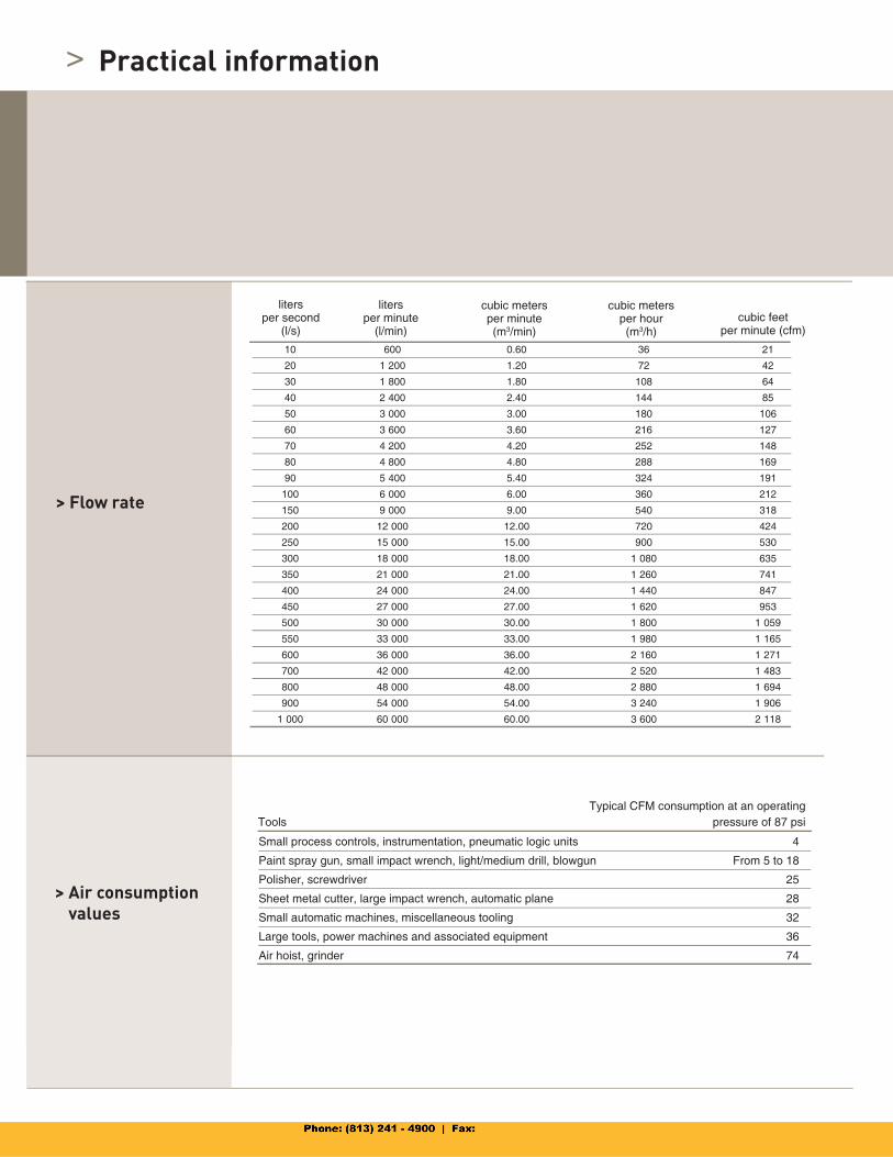
>
> Flow rate
> Air consumption values
10 600 0.60 36 21
20 1 200 1.20 72 42
30 1 800 1.80 108 64
40 2 400 2.40 144 85
50 3 000 3.00 180 106
60 3 600 3.60 216 127
70 4 200 4.20 252 148
80 4 800 4.80 288 169
90 5 400 5.40 324 191
100 6 000 6.00 360 212
150 9 000 9.00 540 318
200 12 000 12.00 720 424
250 15 000 15.00 900 530
300 18 000 18.00 1 080 635
350 21 000 21.00 1 260 741
400 24 000 24.00 1 440 847
450 27 000 27.00 1 620 953
500 30 000 30.00 1 800 1 059
550 33 000 33.00 1 980 1 165
600 36 000 36.00 2 160 1 271
700 42 000 42.00 2 520 1 483
800 48 000 48.00 2 880 1 694
900 54 000 54.00 3 240 1 906
1 000 60 000 60.00 3 600 2 118
litersper second
(l/s)
cubic metersper minute(m3/min)
cubic metersper hour(m3/h)
cubic feetper minute (cfm)
litersper minute
(l/min)
Small process controls, instrumentation, pneumatic logic units 4
Paint spray gun, small impact wrench, light/medium drill, blowgun From 5 to 18
Polisher, screwdriver 25
Sheet metal cutter, large impact wrench, automatic plane 28
Small automatic machines, miscellaneous tooling 32
Large tools, power machines and associated equipment 36
Air hoist, grinder 74
ToolsTypical CFM consumption at an operating
pressure of 87 psi
Practical information
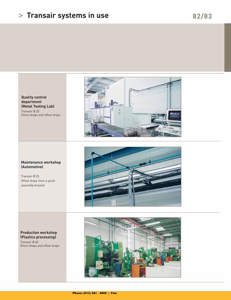
> 82/83Transair systems in use
Quality controldepartment (Metal Testing Lab)Transair Ø 25
Direct drops and offset drops
Maintenance workshop(Automotive)
Transair Ø 25
Offset drops from a quick
assembly bracket
Production workshop(Plastics processing)Transair Ø 40
Direct drops and offset drops
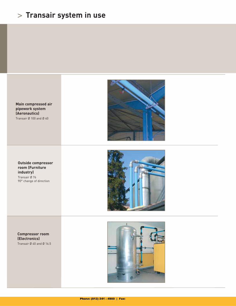
>
Main compressed air pipework system(Aeronautics)Transair Ø 100 and Ø 40
Outside compressor room (Furniture industry)Transair Ø 76
90° change of direction
Compressor room(Electronics)Transair Ø 40 and Ø 16.5
Transair system in use
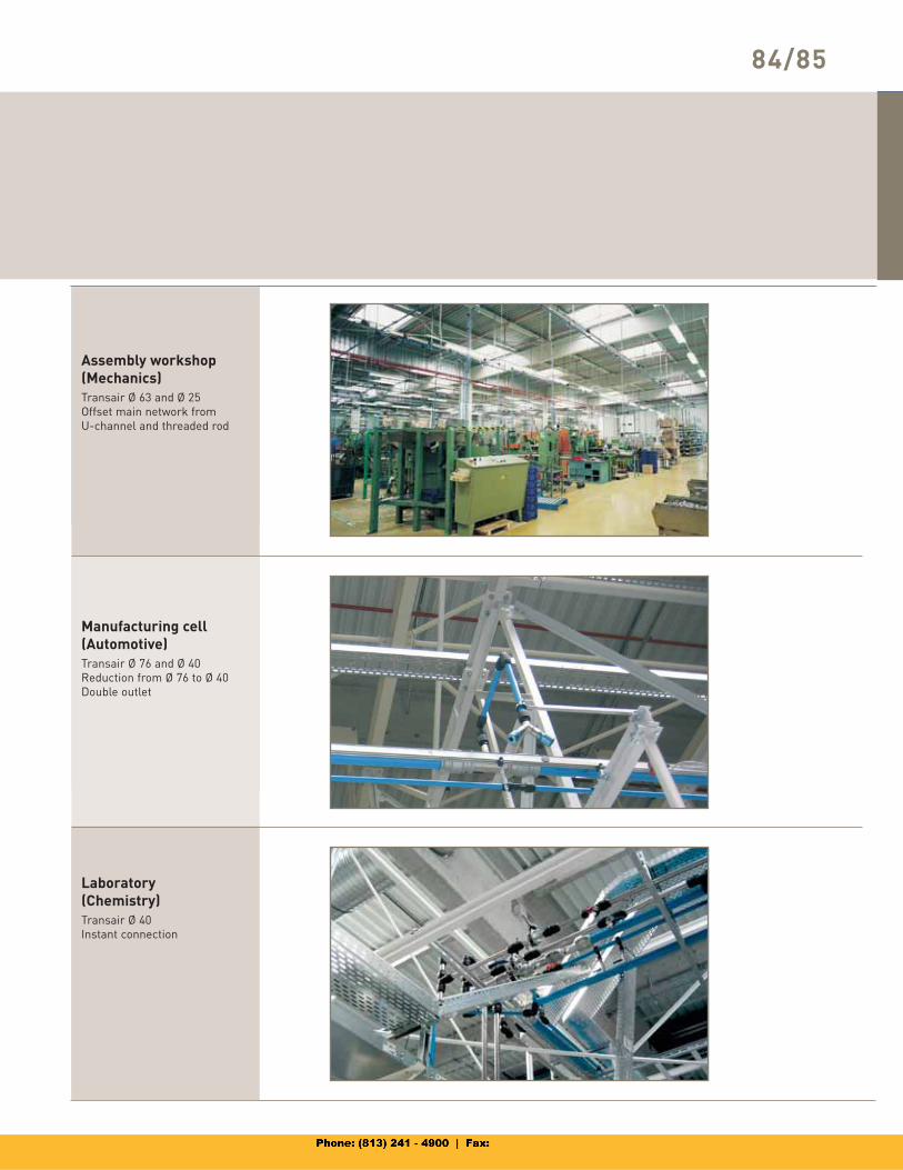
84/85
Assembly workshop (Mechanics)Transair Ø 63 and Ø 25
Offset main network from
U-channel and threaded rod
Manufacturing cell(Automotive)Transair Ø 76 and Ø 40
Reduction from Ø 76 to Ø 40
Double outlet
Laboratory(Chemistry)Transair Ø 40
Instant connection
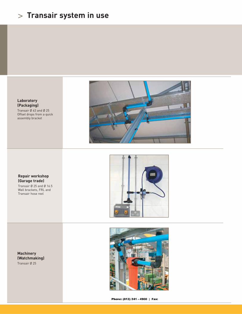
>
Laboratory(Packaging)Transair Ø 63 and Ø 25
Offset drops from a quick
assembly bracket
Repair workshop(Garage trade)Transair Ø 25 and Ø 16.5
Wall brackets, FRL and
Transair hose reel
Machinery(Watchmaking)Transair Ø 25
Transair system in use
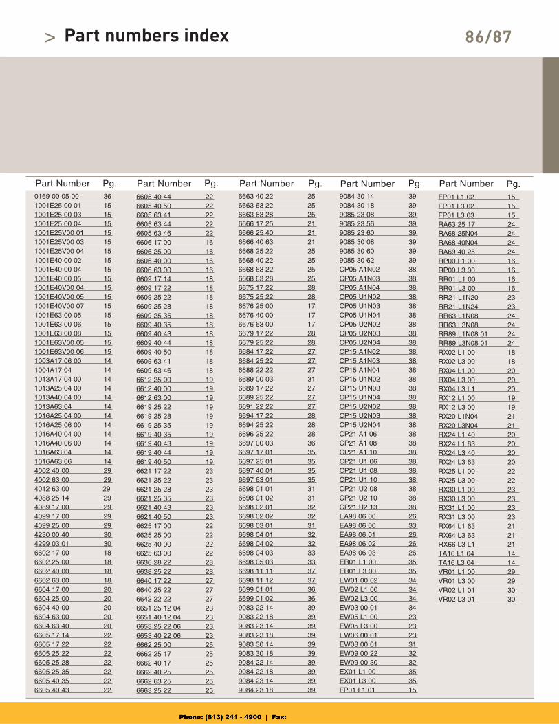
Part Number Part Number Part Number Part Number Part Number0169 00 05 00 361001E25 00 01 151001E25 00 03 151001E25 00 04 151001E25V00 01 151001E25V00 03 151001E25V00 04 151001E40 00 02 151001E40 00 04 151001E40 00 05 151001E40V00 04 151001E40V00 05 151001E40V00 07 151001E63 00 05 151001E63 00 06 151001E63 00 08 151001E63V00 05 151001E63V00 06 151003A17 06 00 141004A17 04 141013A17 04 00 141013A25 04 00 141013A40 04 00 141013A63 04 141016A25 04 00 141016A25 06 00 141016A40 04 00 141016A40 06 00 141016A63 04 141016A63 06 144002 40 00 294002 63 00 294012 63 00 294088 25 14 294089 17 00 294099 17 00 294099 25 00 294230 00 40 304299 03 01 306602 17 00 186602 25 00 186602 40 00 186602 63 00 186604 17 00 206604 25 00 206604 40 00 206604 63 00 206604 63 40 206605 17 14 226605 17 22 226605 25 22 226605 25 28 226605 25 35 226605 40 35 226605 40 43 22
6605 40 44 226605 40 50 226605 63 41 226605 63 44 226605 63 46 226606 17 00 166606 25 00 166606 40 00 166606 63 00 166609 17 14 186609 17 22 186609 25 22 186609 25 28 186609 25 35 186609 40 35 186609 40 43 186609 40 44 186609 40 50 186609 63 41 186609 63 46 186612 25 00 196612 40 00 196612 63 00 196619 25 22 196619 25 28 196619 25 35 196619 40 35 196619 40 43 196619 40 44 196619 40 50 196621 17 22 236621 25 22 236621 25 28 236621 25 35 236621 40 43 236621 40 50 236625 17 00 226625 25 00 226625 40 00 226625 63 00 226636 28 22 286638 25 22 286640 17 22 276640 25 22 276642 22 22 276651 25 12 04 236651 40 12 04 236653 25 22 06 236653 40 22 06 236662 25 00 256662 25 17 256662 40 17 256662 40 25 256662 63 25 256663 25 22 25
6663 40 22 256663 63 22 256663 63 28 256666 17 25 216666 25 40 216666 40 63 216668 25 22 256668 40 22 256668 63 22 256668 63 28 256675 17 22 286675 25 22 286676 25 00 176676 40 00 176676 63 00 176679 17 22 286679 25 22 286684 17 22 276684 25 22 276688 22 22 276689 00 03 316689 17 22 276689 25 22 276691 22 22 276694 17 22 286694 25 22 286696 25 22 286697 00 03 366697 17 01 356697 25 01 356697 40 01 356697 63 01 356698 01 01 316698 01 02 316698 02 01 326698 02 02 326698 03 01 316698 04 01 326698 04 02 326698 04 03 336698 05 03 336698 11 11 376698 11 12 376699 01 01 366699 01 02 369083 22 14 399083 22 18 399083 23 14 399083 23 18 399083 30 14 399083 30 18 399084 22 14 399084 22 18 399084 23 14 399084 23 18 39
9084 30 14 399084 30 18 399085 23 08 399085 23 56 399085 23 60 399085 30 08 399085 30 60 399085 30 62 39CP05 A1N02 38CP05 A1N03 38CP05 A1N04 38CP05 U1N02 38CP05 U1N03 38CP05 U1N04 38CP05 U2N02 38CP05 U2N03 38CP05 U2N04 38CP15 A1N02 38CP15 A1N03 38CP15 A1N04 38CP15 U1N02 38CP15 U1N03 38CP15 U1N04 38CP15 U2N02 38CP15 U2N03 38CP15 U2N04 38CP21 A1 06 38CP21 A1 08 38CP21 A1 10 38CP21 U1 06 38CP21 U1 08 38CP21 U1 10 38CP21 U2 08 38CP21 U2 10 38CP21 U2 13 38EA98 06 00 26EA98 06 00 33EA98 06 01 26EA98 06 02 26EA98 06 03 26ER01 L1 00 35ER01 L3 00 35EW01 00 02 34EW02 L1 00 34EW02 L3 00 34EW03 00 01 34EW05 L1 00 23EW05 L3 00 23EW06 00 01 23EW08 00 01 31EW09 00 22 32EW09 00 30 32EX01 L1 00 35EX01 L3 00 35FP01 L1 01 15
FP01 L1 02 15FP01 L3 02 15FP01 L3 03 15RA63 25 17 24RA68 25N04 24RA68 40N04 24RA69 40 25 24RP00 L1 00 16RP00 L3 00 16RR01 L1 00 16RR01 L3 00 16RR21 L1N20 23RR21 L1N24 23RR63 L1N08 24RR63 L3N08 24RR89 L1N08 01 24RR89 L3N08 01 24RX02 L1 00 18RX02 L3 00 18RX04 L1 00 20RX04 L3 00 20RX04 L3 L1 20RX12 L1 00 19RX12 L3 00 19RX20 L1N04 21RX20 L3N04 21RX24 L1 40 20RX24 L1 63 20RX24 L3 40 20RX24 L3 63 20RX25 L1 00 22RX25 L3 00 22RX30 L1 00 23RX30 L3 00 23RX31 L1 00 23RX31 L3 00 23RX64 L1 63 21RX64 L3 63 21RX66 L3 L1 21TA16 L1 04 14TA16 L3 04 14VR01 L1 00 29VR01 L3 00 29VR02 L1 01 30VR02 L3 01 30
Pg. Pg. Pg. Pg. Pg.
86/87Part numbers index>