advanced digital receiver for distributed instrument … · conclusion. goals enable next ... what...
TRANSCRIPT

Advanced Digital Receiver for Distributed Instrument Arrays
Patrick Smith – University of Florida
MIT Haystack Observatory REU 2012

Overview
● Goals● What is a Digital Receiver?● Hardware● Development Tools● Firmware● Results● Conclusion

Goals
● Enable next generation of radio signal data acquisition
● Use a commercial 'off the shelf' solution– 4DSP FMC104
● Analog to Digital Converter Card
● Interface the 4DSP card with a Xilinx Field Programmable Gate Array (FPGA)
● Develop firmware to implement the interface using a high-level Hardware Description Language (VHDL)

What is a Digital Receiver?
● Radio using Digital Signal Processing● Eliminate most analog components● Can be implemented using:
– Application Specific Integrated Circuit (ASIC)
– Field Programmable Gate Array
– Software
AnalogElectronics
RadioAntenna
Digital Signal Processing
FMC104
A/D Converter Data Network
Xilinx FPGA

Field Programmable Gate Array (FPGA)
● An FPGA is an integrated circuit that is configured after manufacturing
– Reconfigurable
● Used in digital interfacing and signal processing
● Modern tools are simplifying a traditionally complex development cycle

FPGA: South African Rhino Board
● Reconfigurable Hardware Interface for Computing and Radio (open source)
● Developed by the Radar and Remote Sensing Group – University of Cape Town, South Africa
However...However...

FPGA: Xilinx Virtex 6 ML605
● Since the Rhino board has been delayed, we turned to the Virtex 6 ML605 board
EthernetTransfer data
Xilinx FPGA chip
FPGA Mezzanine CardConnect analog-to-digital converter card
USBConnect PC for programming and debugging

Analog-to-Digital Conversion
● 4DSP FMC104 ADC card– 4 channel
– 14-bit
– 250 Msps
● Serial Control– Inter-Integrated Circuit (I2C)
● 2 wire bidirectional serial bus
– Serial Interface for ADC and Clock Control● 4 wire bidirectional serial bus
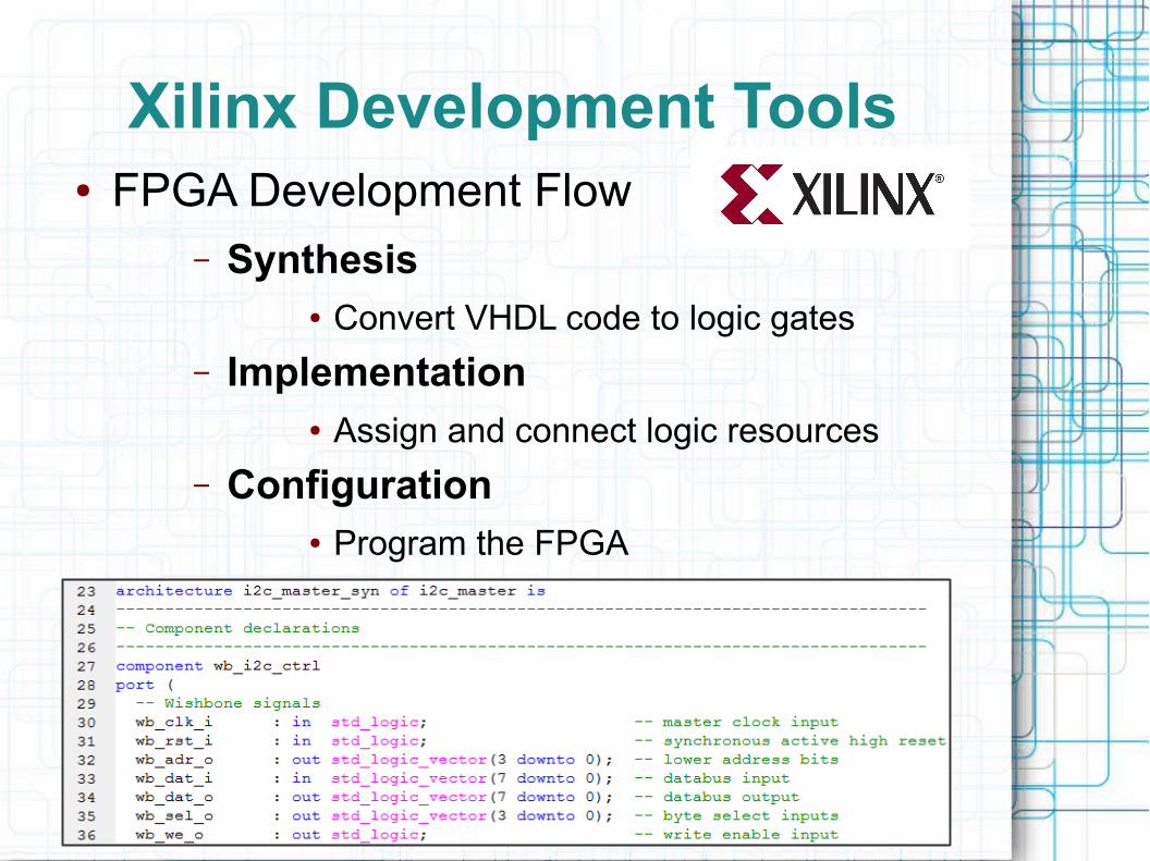
Xilinx Development Tools● FPGA Development Flow
– Synthesis● Convert VHDL code to logic gates
– Implementation ● Assign and connect logic resources
– Configuration● Program the FPGA

Xilinx Debugging Tools
● ChipScope– Integrated CONtroller (ICON)
– Virtual Inputs/Outputs (VIO)
– Integrated Logic Analyzer (ILA)

Firmware
● The ADC to FPGA interface logic– Enables control of the ADC, Clock Chip,
onboard Sensors
– Interfaces data and transfers it for use
● Ultimately the goal is to transfer data out over ethernet
● The Firmware is complex, need to break into smaller pieces for implementation

Results
● 4DSP Provided Firmware for Testing
Pow
er S
pect
rum
(d
b)
Log Periodic FM radio antenna passed through band-pass filter

Results● Focused on interfacing a serial
temperature sensor:– Design approach is similar for control of
other onboard components

Conclusion
● FPGA's are complicated● Xilinx Development tools are 'buggy'● Obscure error messages

Acknowledgments
● My Mentors– Dr. Frank Lind
– Dr. Phil Erickson
● Special thanks– Ching Lue
– K.T. Paul
● The MIT Haystack Community● NSF● My Peers