advanced fibre placement farnborough air show 2012
DESCRIPTION
Advanced Fibre Placement Farnborough Air Show 2012TRANSCRIPT

Confidential 1
Advanced Fibre Placement
Chris Gear

2

Customer Base
Market
Business
Mix
Sector
Market & Customers

Product Strategy
Current Product Portfolio
Engine
Rotatives
Transparencies
& Coatings
Fuselage
Sections Engine
Structures
Nacelle &
Pylon Flying
Surfaces
Protection
Systems
4

Technology – Targeted Innovation
Future Wing
Technologies
Engine
Structures
Engine
Rotatives Transparencies
& Coatings
Ice Protection
Systems
Advanced
Fuselage
Nacelle &
Pylon
Future Product Differentiation
Advanced Process Development
Advanced Metallic Processes
Next Generation Composite Processes
5

6
Advance Fuselages & Flying Surfaces
Current Products
6

BACKGROUND
Automated fibre placement (AFP) started as a development project
in 1982 between Boeing and Cincinnati Machine Tools
After initial development Cincinnati filed a patent in1989
7

Hand Lay Up
Manual processing dominated
composite manufacture
Reliant on optimisation of
material through operator or
ply cutting machines
High waste, but able to
produce complex shapes
Constrained by material life
and operator skill level
Low non recurring cost
8

Filament Winding
First step to automation for the
deposition of tows
Dry fibre has to pass through
resin before deposition on
mandrel
Used in production of
composite parts such as
fishing rods, yacht masts and
missile bodies
Low non recurring cost
9

Automatic Tape Laying
One of the first steps in
automation led to the
introduction of automated tape
laying (ATL) for large, flat panels
Deposition rates around 10kg/ hr
Material widths of 300 or 600mm
25%-40% material waste
Produces large flat or minimal
shaped panels
Mid non recurring cost
10

ATL vs AFP Waste
Quasi Isotropic lay ups require material to be laid in the 0, 45, 90
and 135 degree directions. As the majority of fibre orientation is in
the 45 and 135 degree direction excess material is generated in the
triangle that over hangs the edge of part
Material Waste
Material Waste
11
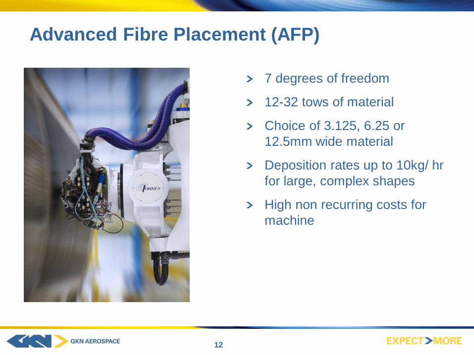
Advanced Fibre Placement (AFP)
7 degrees of freedom
12-32 tows of material
Choice of 3.125, 6.25 or
12.5mm wide material
Deposition rates up to 10kg/ hr
for large, complex shapes
High non recurring costs for
machine
12
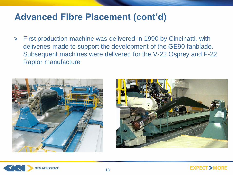
Advanced Fibre Placement (cont’d)
First production machine was delivered in 1990 by Cincinatti, with
deliveries made to support the development of the GE90 fanblade.
Subsequent machines were delivered for the V-22 Osprey and F-22
Raptor manufacture
13

Advanced Fibre Placement (cont’d)
First European research project that established fuselage barrel
manufactures viability was FUBA-COMP, running between 2001-
2006
Fibre placed fuselages in production today include the Hawker
Beechcraft
14

Fuselage Sections
First large scale civil
application of AFP was for
panels of Section 19 for the
A380 manufactured by Airbus
at its Illescas facility near
Madrid
Boeing’s 787 was the first
large commercial use of single
piece fuselage barrel sections
with integrated stiffeners
Typical fuselage single piece
Invar tool weight 80T
15

AFP – the step change
First generation machines utilised on low volume programmes or
high value complex parts
Low deposition rates of around 1kg/ hr on complex shapes
“The change”
Demand for greater deposition rates driven by 787 and A350 XWB
needs
Market opens up to new entrants
Innovation in head designs mean reduced number of movements
and the ability to lay material faster
16

Outer Spar
Mid Spar Inner Spar
A350 XWB Fixed Trailing Edge and Assembly
Design
Contract awarded in 2008 with Airbus
Inner, mid and outer rear carbon spars and fixed trailing (FTE) assembly package
Total length of three spars 27m with a surface accuracy of +/-0.3mm
Required AFP machines for spar lay-up and a robotic assembly area for the fixing of
spars to ribs
Robotic “large scale” assembly operation undertaken by GKN Aerospace (leveraging
skills from the GKN Aerospace – Filton acquisition)
17

Main Wing Spar Manufacture
Machine footprint: 8m x 16m
Working envelope: 13m x 2m x 2m
Band width: 101.6mm (4”)
Tows: 16 off 6.35mm (1/4”) tows
Max. tool weight 3t
18

Engine Fan Case
Machine Footprint: 12 x 6m^2
Fan cases up to Ø of 3.5m
Twin robot configuration, 23 axes in total
Each robot laying-up 75mm wide
prepreg tape
Lay-up rate target: >10kg/hr
Integrated flange forming mechanism
and self heating tool for OoA cure
Latest light weight ATL head
development for robot handling
Cut on the fly capability and advanced
paper tensioning system
19

But It Is Not Just The AFP Machine!
AFP is not just about a machine, it is also about a holistic approach
to a design and manufacturing solution
Compatability between design and manufacturing systems, ie Catia
V5. Can you simulate the manufacturing cycle? What is the right
programming language for your business?
Tooling solutions can be optimised for shape where ATL’s have
been used to produce blanks for forming, offering lower total cost
and reduced manufacturing lead times
20

Where next?
Lightweight robotic systems
Dry fabric
Out of autoclave solutions
Increased agility to produce even more complex shapes
Analytical tools to support complex designs
Consolidation and reduction in parts required to produce assemblies
Multiple heads, multiple tools
21