advanced fuel cells – engineering challenges
TRANSCRIPT

Low temperature acid fuel cells Past Present & Future
S Roy Choudhury
Naval Materials Research Laboratory, Ambernath

Naval Materials Research Laboratory, DRDO
Fuel cellOur mission
To develop totally indigenous fuel cell for Indian armed forces & commercial useAll necessary subsystems like fuel processor, startup systems etc.Spin off benefits
Naval Materials Research Laboratory, DRDO

content
• Attention areas of PAFC and PEMFCs• Improvement options tried by NMRL • Balance of plant developed at NMRL
– Hydrogen provision– Control system– Accessories
• New product range from NMRL

Our Choices …Mission mode systems• Phosphoric acid fuel cell (PAFC)
– The main workhorse• Polymer electrolyte fuel cell (PEMFC)
– Mobile and small systems• Direct borohydride fuel cells with integrated fuel bank
– Handheld systems– UAVs– Soldier as a system
R&D systems• Solid oxide fuel cell (SOFC)
– Material / component stage• Direct carbon fuel cell (DCFC)
Naval Materials Research Laboratory, DRDONaval Materials Research Laboratory, DRDO

Mission mode fuel cell development…
Materials• Fuel cell catalyst• Electrode / acid matrix
• Bipolar plate
Fuel cell system•Process design•Fabrication & installation
Field trials
Accessory design &
development
Product development & packaging
integration
Power conditioner / control electronics
H2 generation / source
development
Testing
Technology transfer
Naval Materials Research Laboratory, DRDO

Achievements so far in fuel cell systems…PAFC
Catalyst Carbon paperElectrodeAcid holder matrixLow cost Graphite gas distributor plate materials
Acid management systemsHumidifiersThermal systemsPower conditioners
Online hydrogen generation devicesNovel hydrogen storage materials
Status :- Limited production for army – Through industry –upto 10kW complete power packs
Naval Materials Research Laboratory, DRDO

Naval Materials Research Laboratory, DRDO
Achievements so far in fuel cell systems…PEMFC /DMFC
Alloy Catalyst (PEMFC,DMFC)
Carbon paperElectrode, (PEMFC/DMFC)
Novel low cost membrane as Nafion substituteMEAs & CCMs (PEMFC)
Graphite gas distributor plate (PEMFC/DMFC)
Humidifiers internal & externalThermal systems & Power conditioners
Status :- Prototypes with all accessories upto 100w – Beta models (PEMFC)

Generation of H2 for possible fuel cell applications
From organic feed stocks
From inorganic feed stocks
Alcohols Hydrocarbons
methanol
ethanol
CNG LPG Naptha, diesel etc.
NH3
Hydrazine
NMRL’s interest
Bio H2 using algae

storage of H2 for possible fuel cell applications
Compressed gas Metal hydrideNaAlH4 etc.
Occluded H2C SWNT, Organo-metallic
framework etc.
Chemical hydrides
Low temperature
storage
High pressure
light weight storage
NaBH4 , CaH2 etc.
NMRL’s interest

Phosphoric Acid Fuel Cells (PAFC)Phosphoric Acid Fuel Cells (PAFC)
Electrolyte Phosphoric Acid
Operating temperature
160°C-200°C
Charge carrier
H+
Prime cell components
Graphite based
Catalyst Platinum
Product water management
Evaporative
Product heat management
Process gas + Independent cooling medium
Moderate power Moderate power densitydensity

Naval Materials Research Laboratory, DRDO
PAFC Materials
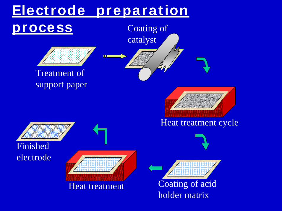
Treatment of support paper
Coating of catalyst
Heat treatment cycle
Finished electrode
Coating of acid holder matrix
Heat treatment
Electrode preparation process

Proton Exchange Membrane Fuel Cells (PEMFC)Proton Exchange Membrane Fuel Cells (PEMFC)
Electrolyte Ion Exchange Membranes
Operating temperature
80°C
Charge carrier
H+
Prime cell components
Carbon based
Catalyst Platinum
Product water management
Evaporative
Product heat management
Process gas + independent cooling medium
Technology ScenarioTechnology Scenario
At R & D stage in IndiaAt R & D stage in IndiaVery sensitive to CO Very sensitive to CO poisoningpoisoning

Naval Materials Research Laboratory, DRDO
anode Pt on carbon (Vulcan XC72) typically 0.1-0.5mg/cm2, bonded on carbon paper/cloth support with nafion binder for ionic bridge
cathode Pt on carbon (Vulcan XC72) typically 5-0.5mg/cm2, bonded on carbon paper/cloth support with nafion binder for ionic bridge
electrolyte Fluro sulphonic acid based proton conducting polymer membrane like nafion, dow membrane etc.
PEMFC materials

Naval Materials Research Laboratory, DRDO
Catalyst layer thicker, Pt/C ~20%Hot pressed assy
Catalyst layer coated on membrane, Pt/C 20-50%Press contact assy
MEACCM
PEMFC basic configuration

Observations -the present systems

Naval Materials Research Laboratory, DRDO
Problems with PAFC are …• Highly corrosive environment allows only graphite / carbon
components•Enhances cost•Special manufacturing
• Higher operating temperature•High startup time
• Need to be run continuously • frequent stopping of hydrogen (start/stop) reduces life
Advantages of PAFC are …• Mature technology with proven very high availability (~85%)• Higher operating temp allows high CO (<2%) allows direct reformer
gas• Multi fuel option• Novel methods promises cost reduction• Highly rugged with long proven life 10,000-50,000 hour

Naval Materials Research Laboratory, DRDO
Problems with PEMFC are …• Low operating temperature limits CO tolerance (in ppm)• High cost of membrane • Fragile in nature & require comprehensive humidification• Low membrane life in actual stack condition• Local overheating melts membrane allowing direct crossover &
failure
Advantages of PEMFC are …• Pressurized versions have high current density• Relatively quicker startup• Only pure H2O as output / spillage• Multiple option for bipolar plate • Suitable for small vehicle / portable power applications

Naval Materials Research Laboratory, DRDO
anode: H2 → 2H+ + 2e−cathode: ½O2 + 2e− + 2H+ → H2OCell : ½O2 + H2 → H2O

Start/stop induced diffusion problem of PAFC
Diffusion layer
Acid holder matrix
Catalyst layer
Normal condition
Acid absorbs water, expands and oozes out by hydraulic pressure
unused condition After restart
Acid shrink back, leaves islands of acid trapped in hydrophobic zone
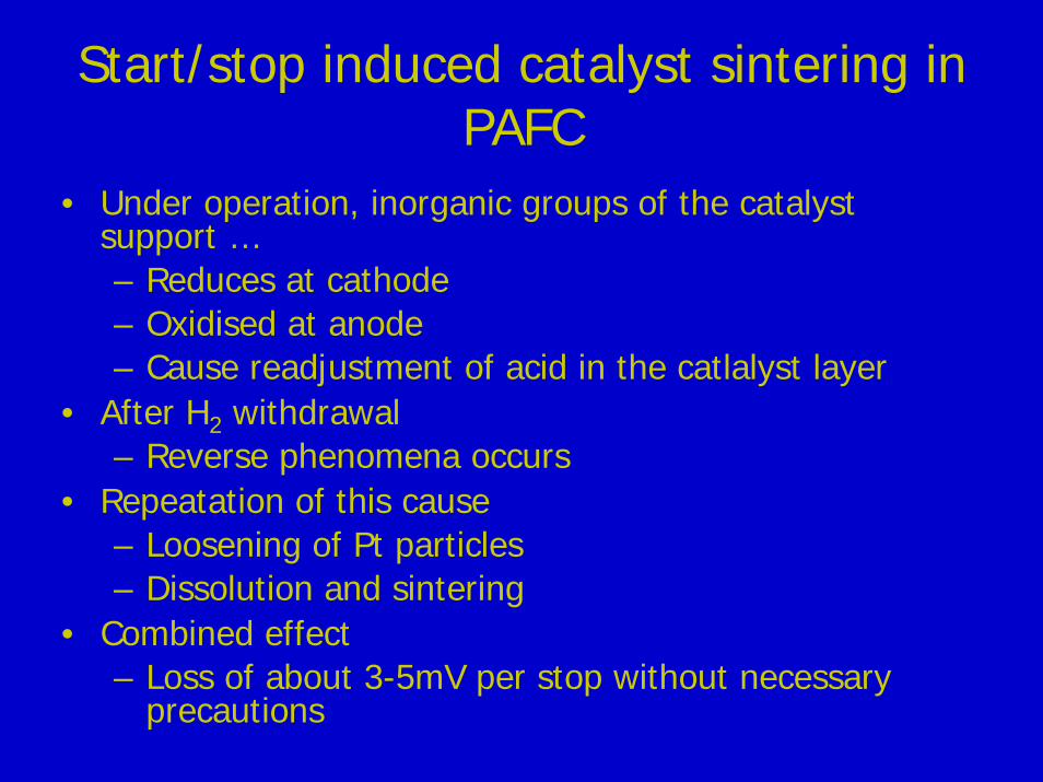
Start/stop induced catalyst sintering in PAFC
• Under operation, inorganic groups of the catalyst support …– Reduces at cathode – Oxidised at anode – Cause readjustment of acid in the catlalyst layer
• After H2 withdrawal– Reverse phenomena occurs
• Repeatation of this cause– Loosening of Pt particles– Dissolution and sintering
• Combined effect – Loss of about 3-5mV per stop without necessary
precautions

The peroxide problem for PEMFC
O2 + 4H+ + 4e => 2H2O E0 = 1.229The peroxide route:-O2 + 2H+ + 2e => 2H2O2 E0 = 0.67H2O2 + 2H+ + 2e => 2H2O E0 = 1.72H2O2 => 2H2O + O2
Zurilla et al. model :-
O2,b -> O2,* H2O2,a H2O
H2O2,* H2O2,b
Cathode kinetics of acid fuel cells

Membrane degradation of PEMFC
• The peroxide generated at cathode attacks and oxidises membrane network– Cleavage of SO3H- chains from the main
backbone– Also oxidises the ionizing polymer in the
cathode– Resulted in low membrane life

Diffusion layer corrosion of PAFC/PEMFC
Used electrode
Carbon paperHydrophobised carbon
paper

The new wave of development

The PEMFC membrane development
Target 1– To make more CO tolerant – Long life– High temperature composite membrane
• H3PO4 doped PBI, PBSH etc.Target 2
– To use pure hydrogen with simple subsystem– Long life– High performance
• Chemically stabilized membranes

Issues for acid doped high temperature membranes
• Will face similar component problems like PAFC
• Low conductivity of the electrolyte • Higher temperature reduces reactant
solubility• Combined effect
– Low performance– High cost

The electrolyte conductivities
Jens et al. Source .. internet

NMRL tries low temperature chemical stabilized membranes with pure H2
generation systems• Control
– PEMFC stacks based on Nafion – 117 membranes with nafion in the electrode
• SPEEK membranes with Nafion and SPEEK in the electrode
• SPEEK membranes chemically stabilized with modified phenolic resin network and Nafion in the electrode

Stabilization of SPEEK
-O- C-
O
CH
-CH -
-C- -O-
-[- O- -O-]--
CH OH OH OH CH-]-
SPEEK+
SPEEK
OH
CH[--
OH
CH OHPF Resin
O
-O-]-
+
-[-O-
SO H
CROSS-LINKED SPEEK
Fig.1
SO H3
2
2
3
2
2
2
2
2
-2H O2CH

Coating of catalyst +binder
Support layer
electrode
Treated membrane
electrode
Hot Press
MEA{
Treated membrane
{
Press assembled
{Support layer
Screen printing of catalyst under vacuum on exfoliated membrane
vacuum
Development of Membrane electrode assembly (MEA) & catalyst coated membrane (CCM)
ME
A CC
M

Performance of PEMFC stack (Nafion), at 700C, 800C humidification
Performance of CCM Vs metal loadings
300
400
500
600
700
800
900
1000
0 200 400 600 800 1000current density mA/cm2
pote
ntia
l mV
0.1mg/cm2- 10%0.2 mg/cm2-20% Pt0.3mg/cm2-30% Pt

SPEEK performance
00.10.20.30.40.50.60.70.80.9
1
0 200 400 600current density(mA/sqcm)
Volta
ge(V
)
nafionSPEEK stabilized SPEEK
Life ~ 200hrs
Life ~1000 hrs

Start / stop tolerant PAFCH3PO4 absorbed Siloxane based microporous gel
• Objective– To develop a gel material that can be coated on
PAFC matrix to reduce crossover / enhance water retention
– To use as an alternative to membrane for PEMFC
• Tested in unit cell/s & stacks– As such like a membrane– Applied over SiC matrix – operated in PAFC mode
Raw materialsH3PO4 and organic siloxane
PO(OH)2-O-Si (OH)3
Followed by the condensation of OH groups and H2O elimination
resulting in the formation of 3-D network connected with bridging oxygen atoms (e.g.,P-O-Si ,Si-O-Si, P-O-P)
The process
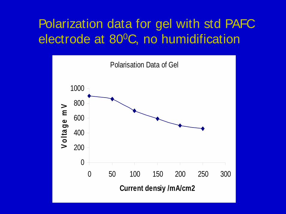
Polarisation Data of Gel
0
200
400
600
800
1000
0 50 100 150 200 250 300
Current densiy /mA/cm2
Vol
tage
mV
Polarization data for gel with std PAFC electrode at 800C, no humidification

Gel coated onto SiC matrix
0200400600800
1000
0 50 100 150 200 250 300 350 400 450
Current Density mA/cm2
Volta
ge m
V
Stable under continuous operation
Polarization data at 1500C, no humidification, excess H3PO4

Properties of Gel
• This gel material containing a large no. microporesand mesopores as revealed by SEM pictures, filled with” liquid “ for fast protonation.
• The gel material shows high thermal stability and lower Humidity dependence.
• The thermal stability was determined by TG-DTA at heating rate of 10 0C/min in air shows two endothermic peak at about 123 0C and 212 0Cdue to the removal of water from mesopores and dehydration of H3PO4.

Balance of plant
Hydrogen provision system

H2 Content & requirement
Material H2evolution wt %
H2 evolution lit/lit @NTP
CH3OH 18.75 5250
CNG 50.00 8
CaH2 9.52 2133**
NaBH4 21.05 4715**
Comp H2 @200atm
100.00 200
** considering powder density=1
~10At ~65% efficiency (~0.6V cell pot)
~6 At 100 % efficiency
~15(with non faradic loss ~18)
At ~65% efficiency (~0.6V cell pot)With 70% utilization
H2 consumption(lpm @ NTP)
1 kWatt power

Pilot methanol reformer – 8-10 lpmhydrogen output for process design and scale up studies (1997)
Compact reformer 1999 (80 lpm hydrogen)
Evolution of methanol
reformer at NMRL
Evolution of methanol
reformer at NMRL

Evolution of methanol
reformer at NMRL
Evolution of methanol
reformer at NMRL
Portable methanol reformerRequirements
• H2 provision for PAFC operation (3 lpm)
• Compact carry pack• No/low power consumption• Rugged, simple
Planar flameless burner
Reformer tubes
Wick holder
Metal blockBoiler/
Superheatertubes
flue
Characteristics • H2 output – 5 lpm (max); • Weight = 6 kg; • Carriable in a shoulder bag
H2 + CO2
CH3OH+H2O
gravity feed
CH3OH for burner
Scheme
reformer

High capacity methanol reformer , 50nM3/hr –2003 hydrogen, suitable to ~60kW PAFC power pack
Process design of reformer – NMRL
Detail engineering, control systems and installation – Xytel India
Commissioning - NMRL
Evolution of methanol
reformer at NMRL
Evolution of methanol
reformer at NMRL

Planar reformer for mobile platformFeatures
• H2 for PAFC operation 1-10kw
• Compact • Low power requirement• Burner efficiency ~55% (without flue heat recovery)
Evolution of methanol
reformer at NMRL
Evolution of methanol
reformer at NMRL

Hydrogen generator for small fuel cells
CaH2 based, one shot cartridge• Capacity 50-150 watt• Controlled water hydrolysis
NaBH4 cracker/sBased on catalytic cracking of alkaline NaBH4
100W (~3lpm H2)•On demand H2
5W (~150cc/min H2)•Pocket size •Orientation free

humidifiers
•650C saturation of H2– high humidification heat
(~150W / kW)•Uses tail H2 from PAFC•No mist carryover•Fast response
Membrane humidifier with tail-hydrogen burner
•Bayonet type moisture generatorConverts part of the inlet H2 to moistureCan be used as stack heater Insertable

Control philosophy and control elements
Control requirements
• Adjustment of H2& oxidant (air) wrt load change
• Adjustment of humidity• Power throttling – through power
electronics

Control scheme – 10kw decoupled mode
DC/DC_AC converter
load
A
Current controller
H2provisioning
system
FF map
Set point map
FT
+
-
++
Air blower /fan
V
HT
FT
HT
Humidity map
+integrator
humidifier
Battery bank
Fuel cell

Over TemperatureOver LoadUnder VoltageOver Voltage
H2 Inlet Solenoid Off
Fan Relay Off
Load Off
Aux Load On
Alarm O/P (individual)
Load On if V>10V
Start Up
Procedure
Pre Heating Timer ON
Heating ON by solenoid powering
Start H2 if temp reached/manual
Fan ON
Micro PLC system for 1kW

Micro Controller Based Control and Display Unit for 2-3 kW PAFC Generator
Controls
I.Temperature : 1.Stack
2.Humidifier
II.Pre heating time
III.H2 Inlet solenoid On/Off
Display
I.Temperature (Status)
II.Voltage (Stack and Converter)
III.Current(Stack and Converter)
Parameter Setting : Through
Panel keys

Products developed at NMRL

Products from NMRL’s stable
700-1000 watt PAFC based UPS / generator with built in compact methanol reformer
Delivers 220V AC, 700-1000VA
100 watt universal power pack (engineered)• Output :- 12+0.05 V DC upto 100 watt (max)
• Hydrogen source by hydride cracking or
by compact catalytic burner based reformer
Naval Materials Research Laboratory, DRDO

8 KW Phosphoric Acid Fuel Cell (PAFC) based power pack
Power output
o 8kW, 220V, 1φ, ac
PAFC stack
o H2/ref gas –air
o 6x1.5KW stacks

DRDO – REVA fuel cell vehicleAn electric vehicle that runs on combined power of fuel cell and battery
The fuel cell charges the battery during idle time and share the load with battery while the vehicle is in operation
Application areas• Patrolling at sensitive areas• Silent personnel transport• High efficiency very low
emission SUV – commercial
Range Battery mode: 80km Hybrid mode: 120km
Speed (max)- ~65kmph
Mileage: - 20km per lit of methyl alcohol
Operation mode – continuous
Other advantages: - silent and very little emissions

burner flue
Exhaust flue
Fuel cell exhaust
T
T
Vector air pump (P2)
MethanolWater
V2
V1
V3
V5V4
a
bc
Solenoid normal operation – a to bControl operation – a to c (exhaust mode)
Reformer
Fuel cell with end-
fitted burners
Burner sideH2 generation side
Spindle pump (P1)
FC burner air pump (P3) C
onve
rter
/Cha
rger Lo
ad
P & ID of Fuel Cell Based Battery Charger for Reva Car

10kW fuel cell based mobile generator car
SHy-Power generator carThe system
Power is generated by a novel electrochemical power device known as fuel cell
A fuel cell stack (a battery of fuel cells) produces DC power directly by reacting hydrogen gas with oxygen in the air.
The hydrogen is generated online by reforming methyl alcohol (CH3OH + H2O = CO2+3H2)
Primary fuel methyl alcohol – no need to carry hydrogen cylinder !!
Salient Features Mobile PowerStable & reliableSilent & Emission freeHighly efficientDuty – Continuous
Application areas• “Drive in” remote, continuous
power for land based troops• Power generation at sensitive
areas• Distributed, green power –
commercial application

The platform:-Infantry tactical vehicle from, VRDE
Fuel cell stacks
H2 generators (methanol reformers)
Control systems
10kW skid mount power pack
reformer

Application areas• Remote onsite power
generation• Can be towed easily by a
small vehicle• Methanol as primary fuel
Trolley mounted version of Shy Power generator
Capacity 10kw continuous

New approaches
System simplification•Hydrogen carrying conduit
– Borone hydride based systems–NaBH4 regeneration for cost reduction–Dimethyl ether based carrier
•Simple Reformer •Can be used like LPG directly in engines•Has high calorific value• low toxicity

Achievement summary
Our fuel cells operate at the top of the world !!