advanced heat exchangers - onda-it.com · pdf file3 rev 1.1 del 2016 note/notes: (1) ps 16 bar...
TRANSCRIPT
A D VA N C E D H E AT E X C H A N G E R S
SSE
SHELL & TUBE EVAPORATORS

2
SHELL & TUBE EVAPORATORSSSE
REV 1.1 del 2016

3 REV 1.1 del 2016
Note/Notes:(1) PS 16 bar lato mantello su richiesta. PS 16 bar shell side on request.
(2) Tmin a -20 °C su richiesta. Tmin at -20 °C on request
ApprovazioneApproval
PS (1)
TS min (2) TS max Categoria (Marcatura)Category (Stamp)Lato Tubi Tubes Side Lato Mantello Shell Side
CE 18 bar 10 (16) bar -10 (-20) °C 90 °C Fino a Cat. IV, 97/23/CEUp to Cat. IV, 97/23/EC
ASME MAWP 235 p.s.i. @ 122 °FMAEWP 145 p.s.i. @ 122 °F - MDMT da rich. cliente
MDMT acc. to customer request 90 °C UM o UUM or U
INFORMAZIONI TECNICHELe principali applicazioni degli evaporatori ad espansione secca SSE sono il raffreddamento dell’acqua in impianti di condizionamento, il raffreddamento di liquidi o miscele incongelabili in impianti di refrigerazione, la produzione di acqua calda in impianti a pompa di calore.I modelli della serie SSE, ottimizzati per uso con R134a e R1234ze, sono tuttavia impiegabili con tutti i refrigeranti di comune utilizzo; tramite il software di selezione ed il supporto del nostro Ufficio Tecnico sarà possibile ottenere la soluzione migliore ad ogni condizione di lavoro.Gli evaporatori a fascio tubiero ONDA della serie SSE hanno capacità frigorifera fino a 2200 kW, e fino a 4 circuiti lato refrigerante.Il fascio tubiero è saldato direttamente al mantello, dunque non estraibile.Gli evaporatori della serie SSE garantiscono un’elevata resa termodinamica realizzando una precisa configurazione del moto controcorrente e la riduzione dei by-pass mediante strette tolleranze di lavorazione ed accoppiamento.L’ottimizzazione del coefficiente di scambio fa degli evaporatori SSE la soluzione per R134a, R1234ze e altri refrigeranti del tipo HFO, con resa specifica più elevata oggi presente sul mercato.In particolare, si raccomanda l’utilizzo degli evaporatori della serie SSE per applicazioni ad alta efficienza, con approcci ridotti (fino a 2 K) e perdite di carico attorno ai 50 ÷ 60 kPa.Le connessioni acqua sono posizionate orizzontalmente, a destra o sinistra con riferimento all’ingresso del refrigerante.I dati dimensionali contenuti in questo catalogo devono intendersi come indicativi in quanto soggetti a tolleranze di fabbricazione. Ci riserviamo di apportare a tali dati, in qualunque momento e senza preavviso, tutte le modifiche ritenute utili e convenienti.
MATERIALII materiali impiegati per la costruzione degli evaporatori a fascio tubiero ONDA sono conformi ai requisiti delle normative Europee e Americana che sovrintendono alla costruzione dei recipienti a pressione.La costruzione standard degli evaporatori a fascio tubiero prevede l’utilizzo dei seguenti materiali:• Testate, piastre tubiere, mantello, connessioni lato acqua e lato refrigerante in
acciaio al carbonio• Tubi scambiatori in rame• Diaframmi in materiale plastico• Guarnizioni esente amianto e O-Ring• Bulloneria in acciaio legatoSu richiesta possono essere utilizzati materiali alternativi.Per materiali non standard e relative rese frigorifere contattare la nostra sede operativa.
ACCESSORII seguenti optional sono fornibili a richiesta:• Staffe saldate• Supporti superiori per compressori• Connessioni flangiate lato acqua• Cavo scaldante• Isolamento standard ed anti UV• Resistenza elettrica• Verniciatura speciale
NORMATIVE, LIMITI D’IMPIEGO, COLLAUDIGli evaporatori della serie SSE sono fornibili sia in versione CE, in accordo alla Direttiva PED, che secondo normative ASME.In fase di produzione vengono effettuati, da personale qualificato, i controlli non distruttivi previsti da tali certificazioni (liquidi penetranti, radiografie, ultrasuoni, etc.)Tutte le unità sono poi sottoposte a prove di pressione e tenuta (a pressione differenziale nel caso di multi circuiti sul lato refrigerante) secondo norme CE o ASME.Tali apparecchi possono essere progettati, prodotti e collaudati in accordo ai regolamenti delle principali società di classifica navale (IACS), quali ABS, DNV-GL, RINA, LRS, BVM e altri.I limiti d’impiego di temperatura e pressione per approvazione CE o ASME sono riassunti nella tabella seguente.
TECHNICAL INFORMATIONThe main applications of SSE dry-expansion evaporators are the water chilling in air conditioning plants, the liquid or brine solutions cooling in refrigeration plants, the water heating in heat pump systems.SSE models are optimized for use with R134a and R1234ze, but can be used with the most common refrigerants; through the selection software and the support of our Technical Department, it will be possible to get the best solution for any working condition.The ONDA shell & tube compact evaporators, SSE series, have cooling capacity range up to 1600 kW and 4 refrigerant circuits.The tube bundle, directly welded to the shell, is non-removable.SSE evaporators can guarantee an elevated thermal performance through a perfect counter-current flow, and the reduction of by-pass flow, thanks to strict mechanical tolerances of the components.Thanks to the optimization of the heat transfer coefficient, the SSE ones are the heat exchangers for R134a, R1234ze and other HFO refrigerants with the highest specific performance today in the market.In particular, we recommend the adoption of the SSE evaporators for high efficiency applications, with low approach (up to 2 K) and pressure drop around 50 ÷ 60 kPa.The water connections are placed horizontally, right or left side when facing the refrigerant inlet header.The dimensional data contained in this catalogue are to be intended indicative taking into account the manufacturing tolerances. We reserve the right to make changes to this catalogue without prior notice
MATERIALSThe materials adopted for ONDA Shell & Tubes evaporators are compliant with the requirements of the European and American pressure vessels codes.The standard construction of the shell & Tubes evaporators consists of the following materials:• Carbon steel for headers, tube-sheets, shell, refrigerant and water connections• Copper for exchanger tubes• Plastic material for baffles• Asbestos free and O-Ring gaskets• Alloys steel bolts and nutsOn request, alternative materials can be used.For out of standard materials, and pertinent cooling capacities, please contact our Technical Department.
ACCESSORIESThe following optionals are available on request:• Welded saddles• Supports for compressors• Flanged water connections• Trace heating• Standard and UV protection insulation• Electrical resistance• Special painting
TESTS, VESSEL CODES, WORKING LIMITS SSE evaporators are available both with CE, and ASME certification.The required non-destructive examinations, as liquid penetrant, X ray, ultrasonic examination and so on, are carried out during the operational phases by qualified personnel.All units are subjected to final test, (at differential pressure in case of multi-circuit refrigerant side) according to CE and ASME standards.All the models of the SSE series can be designed, manufactured and tested in accordance with the rules of the most common naval classification societies (IACS), as ABS, DNV-GL, RINA, LRS, BVM and others.Temperature and pressure working limits for CE and ASME approvals are reported in the table below.

4
SSE
REV 1.1 del 2016
SHELL & TUBE EVAPORATORS
CONSIGLI PER UNA CORRETTA SELEZIONEIl fattore di sporcamento (f.f.) è un elemento importante per il dimensionamento di un evaporatore, quindi si suggerisce una scelta corretta del suo valore in base ai seguenti parametri:
• acqua in circuito chiuso f.f. = 0.000043 m2K/W• acqua in circuito aperto f.f. = 0.000086 m2K/W• soluzioni con glicole < 40% f.f. = 0.000086 m2K/W• soluzioni con glicole ≥ 40% f.f. = 0.000172 m2K/W
Allo scopo di evitare danni allo scambiatore in caso di basse temperature, si evidenziano i punti di congelamento delle soluzioni glicolate nelle varie percentuali.In caso di temperature di lavoro vicine a detti punti, aumentare opportunamente le percentuali di glicole indicate.
INSTALLAZIONE ED USOPer una corretta installazione ed uso dell’evaporatore si suggerisce di:• Montare l’evaporatore in posizione orizzontale.• Evacuare completamente l’aria dall’evaporatore prima dalla fase di caricamento
dell’impianto.• Verificare l’esistenza di un’adeguata contropressione all’uscita acqua
dell’evaporatore in modo da non lasciare lo scarico libero e di creare quindi all’interno dell’evaporatore stesso una perdita di carico almeno uguale a quella di catalogo o calcolo (se a circuito aperto installare all’uscita acqua una valvola di taratura).
• Evitare, a circuito aperto, che durante la fermata della pompa l’evaporatore si svuoti.
• Lasciare l’evaporatore completamente pieno d’acqua o totalmente vuoto in caso di lunghe fermate.
• Analizzare il tipo di acqua, verificandone la compatibilità prima di utilizzare l’evaporatore in circuito aperto.
• Impiegare, ove necessario, soluzioni incongelabili inibite e verificarle nel tempo evitandone il contatto con l’aria.
• Non invertire l’ingresso con l’uscita dell’acqua, per non penalizzare la resa dell’evaporatore.
• Non sottoporre l’evaporatore ad eccessive vibrazioni.• Evitare l’ingresso di corpi estranei nel circuito idraulico.• Evitare di operare con temperature dell’acqua prossime a 0 °C in assenza di
glicole.• Evitare il rischio di cavitazione della pompa e la presenza di gas nel circuito
idraulico.• Impiegare sempre acque o soluzioni incongelabili compatibili con i materiali
dell’evaporatore e non operare con temperature prossime al punto di congelamento.
• Evitare l’uso di acque ricche in cloro (3 ppm max.)• Collegare lo scambiatore alla messa a terra• Non superare la velocità dell’acqua consigliata (consultare le note del programma
di selezione).• Non prevedere parzializzazioni (lato refrigerante) oltre il 40% senza aver prima
contattato ONDA.• Nel caso di utilizzo di valvola elettronica di espansione On/Off, contattare ONDA
per verificarne la compatibilità con l’evaporatore.In caso sia necessario mantenere l’evaporatore a stock, a seguito del drenaggio dell’acqua all’interno, si raccomanda di riempire il mantello con azoto a pressione appena superiore a quella atmosferica.
HINTS FOR A CORRECT SELECTION The fouling factor (f.f.) is fundamental for a correct selection of an evaporator, therefore some useful values are given below: • closed circuit water f.f. = 0.000043 m2K/W• pen circuit water f.f. = 0.000086 m2K/W• solutions with glycol < 40% f.f. = 0.000086 m2K/W• solutions with glycol ≥ 40% f.f. = 0.000172 m2K/W
In order to avoid any damage to the heat exchanger when working at low temperature, the freezing points of the glycol mixtures (of primary brands), are shown.In case of temperatures close to such freezing points, indicated brine concentration should be increased.
INSTALLATION AND OPERATIONFor the most proper installation and operation of the evaporator, the following recommendations shall be observed:• Install the evaporator in horizontal position.• Purge completely the air from the evaporator before the water filling.• Check the presence of a proper pressure at the evaporator water outlet in order to
avoid unloading, and create inside the shell a pressure drop at least equivalent to that one shown in the catalogue or calculated (if operating in open circuit, install a setting valve at the evaporator water outlet).
• Avoid, in open circuit, the evaporator unloading during the circulating pump stopping.• Keep the evaporator completely full of water or leave it totally drained when not in
use for a long time.• Analyze the water properties for checking the compatibility before using the
evaporator in open circuit.• Adopt, when necessary, inhibited brine solutions to be periodically checked avoiding
contact with air.• For not decreasing the evaporator performance, don’t reverse the water inlet and
outlet.• Do not expose the evaporator to excessive vibrations.• Avoid foreign particles entering the water circuit.• Do not operate with water temperature close to 0°C if not mixed with glycol.• Avoid the risk of pump cavitation and the presence of gas in the water circuit.• Use only water or brine solutions compatible with the materials of the evaporator and
don’t operate with temperatures close to freezing point.• Avoid the use of the evaporator with water containing chlorine in high percentage
(content 3 ppm maximum).• Connect to earth ground.• Do not exceed the maximum allowable water flow (see information on software
selection program).• In case of load partialization more than 40%, please consult ONDA for performance
evaluation.• Please contact ONDA before using electrically operated expansion valves, in order
to verify the evaporator’s compatibility.In case the evaporator were kept in stock following the draining of water, it is recommended to fill the shell with nitrogen, at a pressure just above the atmospheric one.
Punto di congelamentoFreezing Point [°C]
Glicole Etilenico [% peso]Ethylene Glycol [% weight]
Glicole Propilenico [% peso]Propylene Glycol [% weight]
-5 12 16
-10 22 26
-15 30 34
-20 36 40
-25 40 44
-30 44 48
-35 48 52
-40 52 56
5 REV 1.1 del 2016
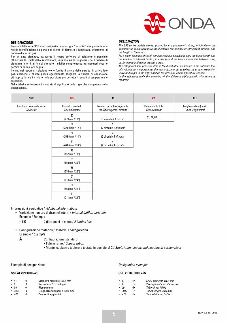
DESIGNAZIONEI modelli della serie SSE sono designati con una sigla “parlante”, che permette una rapida identificazione da parte del cliente di diametro e lunghezza, unitamente al numero di circuiti gas.Per un dato diametro, attraverso il nostro software di selezione è possibile ottimizzare la scelta dello scambiatore, variando sia la lunghezza che il numero di diaframmi interni, al fine di ottenere il miglior compromesso tra ingombri, resa, e perdite di carico lato acqua.Inoltre, nel report di selezione viene fornito il valore delle perdite di carico lato gas, cosicché il cliente possa agevolmente scegliere la valvola di espansione più appropriata e installare nella posizione più corretta i sensori di temperatura e pressione.Nella tabella sottostante è illustrato il significato delle sigle che compaiono nella designazione.
Esempio di designazione
SSE 41.209.3000 +2S
• 41 Diametro mantello 406.4 mm• 2 Versione a 2 circuiti gas• 09 Riempimento• 3000 Lunghezza tubi pari a 3000 mm• +2S Due setti aggiuntivi
DESIGNATIONThe SSE series models are designated by an alphanumeric string, which allows the customer to easily recognize the diameter, the number of refrigerant circuits, and the length of the tubes.For a given diameter, through our software it is possible to vary the tubes length and the number of internal baffles, in order to find the best compromise between size, performance and water pressure drop.The refrigerant side pressure drop in the distributor is indicated in the software too: this value is very important for the customer, in order to select the proper expansion valve and to put in the right position the pressure and temperature sensors.In the following table the meaning of the different alphanumeric characters is reported.
Designation example
SSE 41.209.3000 +2S
• 41 Shell diameter 406.4 mm• 2 2 refrigerant circuits version• 09 Tube-sheet filling• 3000 Tubes length 3000 mm• +2S Two additional baffles
SSE DD. C XX. LLLL
Identificazione della serieSeries ID
Diametro mantelloShell diameter
Numero circuiti refrigeranteNo. Of refrigerant circuits
Riempimento tubiTubes amount
Lunghezza tubi (mm)Tubes length (mm)
27(273 mm / 10”)
1(1 circuito / 1 circuit) 01, 02, 03,…
32(323.9 mm / 12”)
2(2 circuiti / 2 circuits)
36(355.6 mm / 14”)
3(3 circuiti / 3 circuits)
41(406.4 mm / 16”)
4(4 circuiti / 4 circuits)
46(457 mm / 18”)
51(508 mm / 20”)
56(558 mm / 22”)
61(610 mm / 24”)
66(660 mm / 26”)
71(711 mm / 28”)
Informazioni aggiuntive / Additional informations: • Variazione numero diaframmi interni / Internal baffles variation Esempio / Example - 2S 2 diaframmi in meno / 2 baffles less
• Configurazione materiali / Materials configuration Esempio / Example A Configurazione standard • Tubi in rame / Copper tubes • Mantello, piastre tubiere e testate in acciaio al C / Shell, tubes-sheets and headers in carbon steel
6
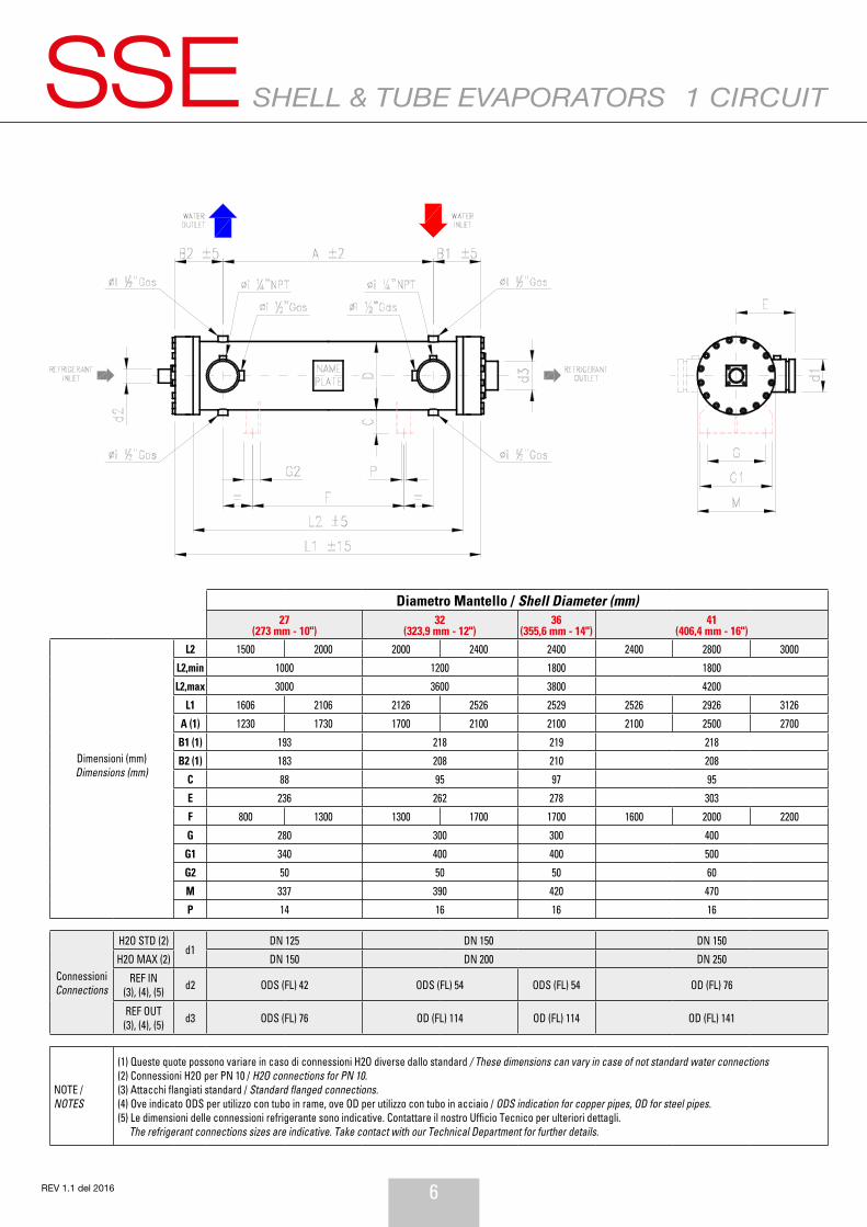
SHELL & TUBE EVAPORATORSSSE 1 CIRCUIT
REV 1.1 del 2016
Diametro Mantello / Shell Diameter (mm)27
(273 mm - 10")32
(323,9 mm - 12")36
(355,6 mm - 14")41
(406,4 mm - 16")
Dimensioni (mm)Dimensions (mm)
L2 1500 2000 2000 2400 2400 2400 2800 3000
L2,min 1000 1200 1800 1800
L2,max 3000 3600 3800 4200
L1 1606 2106 2126 2526 2529 2526 2926 3126
A (1) 1230 1730 1700 2100 2100 2100 2500 2700
B1 (1) 193 218 219 218
B2 (1) 183 208 210 208
C 88 95 97 95
E 236 262 278 303
F 800 1300 1300 1700 1700 1600 2000 2200
G 280 300 300 400
G1 340 400 400 500
G2 50 50 50 60
M 337 390 420 470
P 14 16 16 16
Connessioni Connections
H2O STD (2)d1
DN 125 DN 150 DN 150
H2O MAX (2) DN 150 DN 200 DN 250
REF IN(3), (4), (5) d2 ODS (FL) 42 ODS (FL) 54 ODS (FL) 54 OD (FL) 76
REF OUT(3), (4), (5) d3 ODS (FL) 76 OD (FL) 114 OD (FL) 114 OD (FL) 141
NOTE / NOTES
(1) Queste quote possono variare in caso di connessioni H2O diverse dallo standard / These dimensions can vary in case of not standard water connections(2) Connessioni H2O per PN 10 / H2O connections for PN 10.(3) Attacchi flangiati standard / Standard flanged connections.(4) Ove indicato ODS per utilizzo con tubo in rame, ove OD per utilizzo con tubo in acciaio / ODS indication for copper pipes, OD for steel pipes.(5) Le dimensioni delle connessioni refrigerante sono indicative. Contattare il nostro Ufficio Tecnico per ulteriori dettagli. The refrigerant connections sizes are indicative. Take contact with our Technical Department for further details.

7 REV 1.1 del 2016
2 CIRCUITS
Diametro Mantello / Shell Diameter (mm)27
(273 mm - 10”)32
(323,9 mm - 12”)36
(355,6 mm - 14”)41
(406,4 mm - 16”)46
(457 mm / 18”)51
(508 mm / 20”)56
(558 mm / 22”)61
(610 mm / 24”)
Dimensioni (mm) Dimensions (mm)
L2 1500 2000 2000 2400 2400 2400 2800 3000 3000 3000 3400 3000 3000 3400
L2,min 1000 1200 1800 1800 2000 2200 2400 2600
L2,max 3000 3600 3800 4200 4400 5000 5000 6000
L1 1606 2106 2126 2526 2529 2526 2926 3126 3126 3126 3526 3127 3133 3533
A (1) 1230 1730 1600 2000 2100 2100 2500 2700 2610 2610 3010 2550 2500 2900
B1 (1) 193 218 219 218 263 263 295 303
B2 (1) 183 208 210 208 253 253 282 280
C 88 95 95 97 94 94 97 130
E 236 262 278 303 328 354 380 425
F 1100 1600 1300 1700 2000 1600 2000 2200 2200 2200 2600 2200 2200 2600
G 280 300 300 400 400 400 400 500
G1 340 400 400 500 500 500 500 600
G2 50 50 50 60 60 60 60 80
M 337 390 420 470 520 572 620 680
P 14 16 16 16 16 18 18 18
Connessioni Connections
H2O STD (2)d1
DN 125 DN 150 DN 150 DN 200 DN 200 DN 200 DN 250 DN 250
H2O MAX (2) DN 150 DN 200 DN 250 DN 250 DN 250 DN 250 DN 250 DN 250
REF IN (3), (4), (5) d2 ODS (FL) 42 ODS (FL) 42 ODS (FL) 54 ODS (FL) 54 ODS (FL) 54 ODS (FL) 54 ODS (FL) 54 ODS (FL) 54
REF OUT (3), (4), (5) d3 ODS (FL) 77 OD (FL) 89 OD (FL) 89 OD (FL) 114 OD (FL) 114 OD (FL) 141 OD (FL) 141 OD (FL) 141
NOTE / NOTES
(1) Queste quote possono variare in caso di connessioni H2O diverse dallo standard / These dimensions can vary in case of not standard water connections(2) Connessioni H2O per PN 10 / H2O connections for PN 10.(3) Attacchi flangiati standard / Standard flanged connections.(4) Ove indicato ODS per utilizzo con tubo in rame, ove OD per utilizzo con tubo in acciaio / ODS indication for copper pipes, OD for steel pipes.(5) Le dimensioni delle connessioni refrigerante sono indicative. Contattare il nostro Ufficio Tecnico per ulteriori dettagli.The refrigerant connections sizes are indicative. Take contact with our Technical Department for further details.

8
SSE
REV 1.1 del 2016
SHELL & TUBE EVAPORATORS 3 CIRCUITS
Diametro Mantello / Shell Diameter (mm)32
(323,9 mm - 12”)36
(355,6 mm - 14”)41
(406,4 mm - 16”)46
(457 mm / 18”)51
(508 mm / 20”)56
(558 mm / 22”)61
(610 mm / 24”)66
(660 mm / 26”)71
(711 mm / 28”)
Dimensioni (mm) Dimensions (mm)
L2 2000 2400 2400 2400 2800 3000 3000 3000 3400 3000 3000 3400 3500 4000 3500 4000
L2,min 1200 1800 1800 2000 2200 2400 2600 2600 2600
L2,max 3600 3800 4200 4400 5000 5000 6000 6000 6000
L1 2126 2526 2529 2526 2926 3126 3126 3126 3526 3127 3133 3533 3650 4150 3680 4180
A (1) 1600 2000 2100 2100 2500 2700 2610 2610 3010 2550 2500 2900 2970 3470 2970 3470
B1 (1) 218 219 218 263 263 295 303 345 365
B2 (1) 208 210 208 253 253 282 280 335 345
C (6) 95 95 97 94 94 97 130 150 150
E 262 278 303 328 354 380 425 480 506
F 1300 1700 2000 1600 2000 2200 2200 2200 2600 2200 2200 2600 2350 2850 2350 2850
G 300 300 400 400 400 400 500 400 500
G1 400 400 500 500 500 500 600 570 620
G2 50 50 60 60 60 60 80 150 150
M 390 420 470 520 572 620 680 770 820
P 16 16 16 16 18 18 18 22 22
Connessioni Connections
H2O STD (2)d1
DN 150 DN 150 DN 200 DN 200 DN 200 DN 250 DN 250 DN 300 DN 300
H2O MAX (2) DN 200 DN 250 DN 250 DN 250 DN 250 DN 250 DN 250 DN 300 DN 300
REF IN (3), (4), (5) d2 ODS (FL) 35 ODS (FL) 35 ODS (FL) 42 ODS (FL) 42 ODS (FL) 54 ODS (FL) 54 ODS (FL) 64
REF OUT (3), (4), (5) d3 ODS (FL) 54 OD (FL) 89 OD (FL) 89 OD (FL) 114 OD (FL) 114 OD (FL) 141 OD (FL) 168
Note / Notes
(1) Queste quote possono variare in caso di connessioni H2O diverse dallo standard / These dimensions can vary in case of not standard water connections(2) Connessioni H2O per PN 10 / H2O connections for PN 10.(3) Attacchi flangiati standard / Standard flanged connections.(4) Ove indicato ODS per utilizzo con tubo in rame, ove OD per utilizzo con tubo in acciaio / ODS indication for copper pipes, OD for steel pipes.(5) Le dimensioni delle connessioni refrigerante sono indicative. Contattare il nostro Ufficio Tecnico per ulteriori dettagli. The refrigerant connections sizes are indicative. Take contact with our Technical Department for further details.(6) Le staffe per mantelli da 610, 660 e 711 mm presentano un design speciale rinforzato. / Saddles for 610 and 660 and 711 mm shell diameter have a special reinforced design.
9 REV 1.1 del 2016
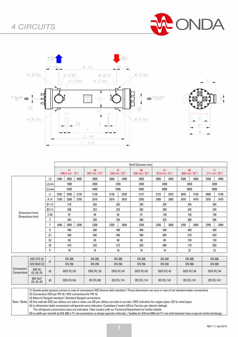
4 CIRCUITS
Shell Diameter (mm)
41 (406,4 mm - 16”)
46 (457 mm / 18”)
51 (508 mm / 20”)
56 (558 mm / 22”)
61 (610 mm / 24”)
66 (660 mm / 26”)
71 (711 mm / 28”)
Dimensioni (mm) Dimensions (mm)
L2 2400 2800 3000 3000 3000 3400 3000 3000 3400 3500 4000 3500 4000
L2,min 1800 2000 2200 2400 2600 2600 2600
L2,max 4200 4400 5000 5000 6000 6000 6000
L1 2526 2926 3126 3126 3126 3526 3127 3133 3533 3650 4150 3680 4180
A (1) 2100 2500 2700 2610 2610 3010 2550 2500 2900 2970 3470 2970 3470
B1 (1) 218 263 263 295 303 345 365
B2 (1) 208 253 253 282 280 335 345
C (6) 97 94 94 97 130 150 150
E 303 328 354 380 425 480 506
F 1600 2000 2200 2200 2200 2600 2200 2200 2600 2350 2850 2350 2850
G 400 400 400 400 500 400 500
G1 500 500 500 500 600 570 620
G2 60 60 60 60 80 150 150
M 470 520 572 620 680 770 820
P 16 16 18 18 18 22 22
Connessioni Connections
H2O STD (2)d1
DN 200 DN 200 DN 200 DN 250 DN 250 DN 300 DN 300
H2O MAX (2) DN 250 DN 250 DN 250 DN 250 DN 250 DN 300 DN 300
REF IN (3), (4), (5) d2 ODS (FL) 35 ODS (FL) 35 ODS (FL) 42 ODS (FL) 42 ODS (FL) 42 ODS (FL) 54 ODS (FL) 54
REF OUT (3), (4), (5) d3 ODS (FL) 64 OD (FL) 89 OD (FL) 114 OD (FL) 114 OD (FL) 141 OD (FL) 141 OD (FL) 141
Note / Notes
(1) Queste quote possono variare in caso di connessioni H2O diverse dallo standard / These dimensions can vary in case of not standard water connections(2) Connessioni H2O per PN 10 / H2O connections for PN 10.(3) Attacchi flangiati standard / Standard flanged connections.(4) Ove indicato ODS per utilizzo con tubo in rame, ove OD per utilizzo con tubo in acciaio / ODS indication for copper pipes, OD for steel pipes.(5) Le dimensioni delle connessioni refrigerante sono indicative. Contattare il nostro Ufficio Tecnico per ulteriori dettagli. The refrigerant connections sizes are indicative. Take contact with our Technical Department for further details.(6) Le staffe per mantelli da 610, 660 e 711 mm presentano un design speciale rinforzato. / Saddles for 610 and 660 and 711 mm shell diameter have a special reinforced design.
10
SHELL & TUBE EVAPORATORSSSE
REV 1.1 del 2016
1 CIRCUIT
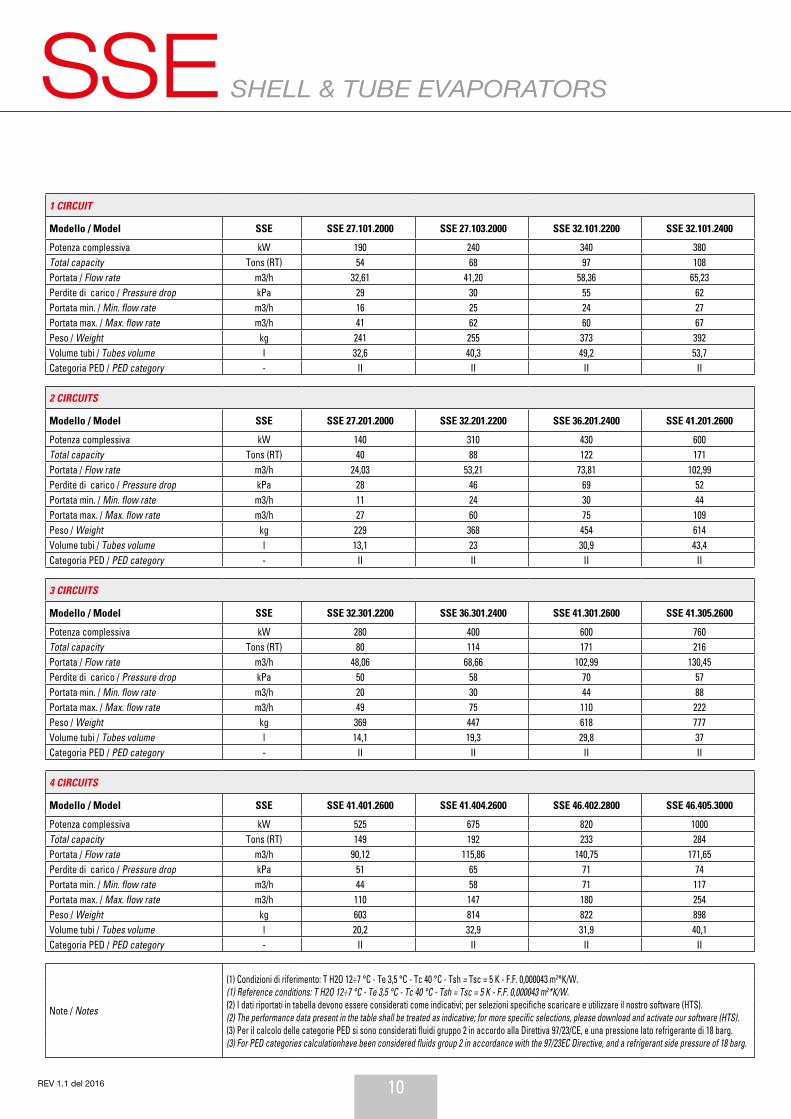
Modello / Model SSE SSE 27.101.2000 SSE 27.103.2000 SSE 32.101.2200 SSE 32.101.2400 SSE 36.101.2400 SSE 41.101.2400 SSE 41.102.2600 SSE 41.103.2800 SSE 41.105.2800 SSE 41.105.3000
Potenza complessiva kW 190 240 340 380 480 550 665 790 885 950Total capacity Tons (RT) 54 68 97 108 136 156 189 225 252 270Portata / Flow rate m3/h 32,61 41,20 58,36 65,23 82,39 94,41 114,15 135,60 151,91 163,07Perdite di carico / Pressure drop kPa 29 30 55 62 56 59 55 77 67 74Portata min. / Min. flow rate m3/h 16 25 24 27 36 40 59 65 97 106Portata max. / Max. flow rate m3/h 41 62 60 67 90 100 148 163 246 254Peso / Weight kg 241 255 373 392 461 595 636 678 706 736Volume tubi / Tubes volume l 32,6 40,3 49,2 53,7 65,6 84,2 98,9 114,6 130 139,3Categoria PED / PED category - II II II II III III III III III III
2 CIRCUITS
Modello / Model SSE SSE 27.201.2000 SSE 32.201.2200 SSE 36.201.2400 SSE 41.201.2600 SSE 41.206.2600 SSE 46.202.2800 SSE 51.201.3000 SSE 51.204.3000 SSE 56.203.3400 SSE 61.201.3400
Potenza complessiva kW 140 310 430 600 730 860 1010 1200 1550 1700Total capacity Tons (RT) 40 88 122 171 208 245 287 341 441 483Portata / Flow rate m3/h 24,03 53,21 73,81 102,99 125,30 147,62 173,37 205,98 266,06 291,80Perdite di carico / Pressure drop kPa 28 46 69 52 58 72 76 80 86 97Portata min. / Min. flow rate m3/h 11 24 30 44 58 73 88 132 164 175Portata max. / Max. flow rate m3/h 27 60 75 109 146 184 222 254 397 397Peso / Weight kg 229 368 454 614 647 827 1002 1062 1385 1716Volume tubi / Tubes volume l 13,1 23 30,9 43,4 52,5 65,1 79,3 96,1 129,4 148,5Categoria PED / PED category - II II II II II III III III III III
3 CIRCUITS
Modello / Model SSE SSE 32.301.2200 SSE 36.301.2400 SSE 41.301.2600 SSE 41.305.2600 SSE 46.304.2800 SSE 51.304.3000 SSE 56.303.3000 SSE 61.301.3200 SSE 66.301.3200 SSE 71.301.3200
Potenza complessiva kW 280 400 600 760 900 1150 1380 1500 2000 2200Total capacity Tons (RT) 80 114 171 216 256 327 392 427 569 626Portata / Flow rate m3/h 48,06 68,66 102,99 130,45 154,48 197,40 236,88 257,47 343,30 377,63Perdite di carico / Pressure drop kPa 50 58 70 57 56 73 88 77 140 124Portata min. / Min. flow rate m3/h 20 30 44 88 109 132 136 162 160 177Portata max. / Max. flow rate m3/h 49 75 110 222 254 254 344 397 407 449Peso / Weight kg 369 447 618 777 853 1060 1289 1633 2069 2397Volume tubi / Tubes volume l 14,1 19,3 29,8 37 48,3 63,7 80,1 88,6 112,5 128,3Categoria PED / PED category - II II II II II III III III III III
4 CIRCUITS
Modello / Model SSE SSE 41.401.2600 SSE 41.404.2600 SSE 46.402.2800 SSE 46.405.3000 SSE 51.404.3200 SSE 56.403.3200 SSE 61.401.3200 SSE 66.401.3200 SSE 66.401.3400 SSE 71.401.3200
Potenza complessiva kW 525 675 820 1000 1200 1400 1500 1800 2000 2200Total capacity Tons (RT) 149 192 233 284 341 398 427 512 569 626Portata / Flow rate m3/h 90,12 115,86 140,75 171,65 205,98 240,31 257,47 308,97 343,30 377,63Perdite di carico / Pressure drop kPa 51 65 71 74 76 83 77 92 107 124Portata min. / Min. flow rate m3/h 44 58 71 117 143 147 162 166 179 177Portata max. / Max. flow rate m3/h 110 147 180 254 254 374 397 420 455 449Peso / Weight kg 603 814 822 898 1093 1307 1632 2042 2107 2400Volume tubi / Tubes volume l 20,2 32,9 31,9 40,1 49,9 60,1 66,4 80,7 85,8 96,6Categoria PED / PED category - II II II II II III III III III III
Note / Notes
(1) Condizioni di riferimento: T H2O 12÷7 °C - Te 3,5 °C - Tc 40 °C - Tsh = Tsc = 5 K - F.F. 0,000043 m2*K/W.(1) Reference conditions: T H2O 12÷7 °C - Te 3,5 °C - Tc 40 °C - Tsh = Tsc = 5 K - F.F. 0,000043 m2*K/W.(2) I dati riportati in tabella devono essere considerati come indicativi; per selezioni specifiche scaricare e utilizzare il nostro software (HTS).(2) The performance data present in the table shall be treated as indicative; for more specific selections, please download and activate our software (HTS).(3) Per il calcolo delle categorie PED si sono considerati fluidi gruppo 2 in accordo alla Direttiva 97/23/CE, e una pressione lato refrigerante di 18 barg.(3) For PED categories calculationhave been considered fluids group 2 in accordance with the 97/23EC Directive, and a refrigerant side pressure of 18 barg.
(4) Il volume lato tubi è per singolo circuito refrigerante.(4) The tubes side volume is for single refrigerant circuit.(5) Verificare sempre le perdite di carico lato refrigerante, come riportate nel software di selezione, onde dimensionare correttamente la valvola di espansione.(5) The refrigerant pressure drop in the evaporator shall always be checked in the selection software, in order to select the most reliable expansion valve.
11 REV 1.1 del 2016
PERFORMANCE TABLE
1 CIRCUIT
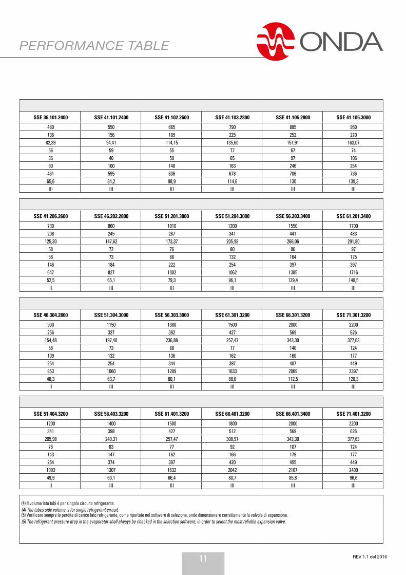
Modello / Model SSE SSE 27.101.2000 SSE 27.103.2000 SSE 32.101.2200 SSE 32.101.2400 SSE 36.101.2400 SSE 41.101.2400 SSE 41.102.2600 SSE 41.103.2800 SSE 41.105.2800 SSE 41.105.3000
Potenza complessiva kW 190 240 340 380 480 550 665 790 885 950Total capacity Tons (RT) 54 68 97 108 136 156 189 225 252 270Portata / Flow rate m3/h 32,61 41,20 58,36 65,23 82,39 94,41 114,15 135,60 151,91 163,07Perdite di carico / Pressure drop kPa 29 30 55 62 56 59 55 77 67 74Portata min. / Min. flow rate m3/h 16 25 24 27 36 40 59 65 97 106Portata max. / Max. flow rate m3/h 41 62 60 67 90 100 148 163 246 254Peso / Weight kg 241 255 373 392 461 595 636 678 706 736Volume tubi / Tubes volume l 32,6 40,3 49,2 53,7 65,6 84,2 98,9 114,6 130 139,3Categoria PED / PED category - II II II II III III III III III III
2 CIRCUITS
Modello / Model SSE SSE 27.201.2000 SSE 32.201.2200 SSE 36.201.2400 SSE 41.201.2600 SSE 41.206.2600 SSE 46.202.2800 SSE 51.201.3000 SSE 51.204.3000 SSE 56.203.3400 SSE 61.201.3400
Potenza complessiva kW 140 310 430 600 730 860 1010 1200 1550 1700Total capacity Tons (RT) 40 88 122 171 208 245 287 341 441 483Portata / Flow rate m3/h 24,03 53,21 73,81 102,99 125,30 147,62 173,37 205,98 266,06 291,80Perdite di carico / Pressure drop kPa 28 46 69 52 58 72 76 80 86 97Portata min. / Min. flow rate m3/h 11 24 30 44 58 73 88 132 164 175Portata max. / Max. flow rate m3/h 27 60 75 109 146 184 222 254 397 397Peso / Weight kg 229 368 454 614 647 827 1002 1062 1385 1716Volume tubi / Tubes volume l 13,1 23 30,9 43,4 52,5 65,1 79,3 96,1 129,4 148,5Categoria PED / PED category - II II II II II III III III III III
3 CIRCUITS
Modello / Model SSE SSE 32.301.2200 SSE 36.301.2400 SSE 41.301.2600 SSE 41.305.2600 SSE 46.304.2800 SSE 51.304.3000 SSE 56.303.3000 SSE 61.301.3200 SSE 66.301.3200 SSE 71.301.3200
Potenza complessiva kW 280 400 600 760 900 1150 1380 1500 2000 2200Total capacity Tons (RT) 80 114 171 216 256 327 392 427 569 626Portata / Flow rate m3/h 48,06 68,66 102,99 130,45 154,48 197,40 236,88 257,47 343,30 377,63Perdite di carico / Pressure drop kPa 50 58 70 57 56 73 88 77 140 124Portata min. / Min. flow rate m3/h 20 30 44 88 109 132 136 162 160 177Portata max. / Max. flow rate m3/h 49 75 110 222 254 254 344 397 407 449Peso / Weight kg 369 447 618 777 853 1060 1289 1633 2069 2397Volume tubi / Tubes volume l 14,1 19,3 29,8 37 48,3 63,7 80,1 88,6 112,5 128,3Categoria PED / PED category - II II II II II III III III III III
4 CIRCUITS
Modello / Model SSE SSE 41.401.2600 SSE 41.404.2600 SSE 46.402.2800 SSE 46.405.3000 SSE 51.404.3200 SSE 56.403.3200 SSE 61.401.3200 SSE 66.401.3200 SSE 66.401.3400 SSE 71.401.3200
Potenza complessiva kW 525 675 820 1000 1200 1400 1500 1800 2000 2200Total capacity Tons (RT) 149 192 233 284 341 398 427 512 569 626Portata / Flow rate m3/h 90,12 115,86 140,75 171,65 205,98 240,31 257,47 308,97 343,30 377,63Perdite di carico / Pressure drop kPa 51 65 71 74 76 83 77 92 107 124Portata min. / Min. flow rate m3/h 44 58 71 117 143 147 162 166 179 177Portata max. / Max. flow rate m3/h 110 147 180 254 254 374 397 420 455 449Peso / Weight kg 603 814 822 898 1093 1307 1632 2042 2107 2400Volume tubi / Tubes volume l 20,2 32,9 31,9 40,1 49,9 60,1 66,4 80,7 85,8 96,6Categoria PED / PED category - II II II II II III III III III III
Note / Notes
(1) Condizioni di riferimento: T H2O 12÷7 °C - Te 3,5 °C - Tc 40 °C - Tsh = Tsc = 5 K - F.F. 0,000043 m2*K/W.(1) Reference conditions: T H2O 12÷7 °C - Te 3,5 °C - Tc 40 °C - Tsh = Tsc = 5 K - F.F. 0,000043 m2*K/W.(2) I dati riportati in tabella devono essere considerati come indicativi; per selezioni specifiche scaricare e utilizzare il nostro software (HTS).(2) The performance data present in the table shall be treated as indicative; for more specific selections, please download and activate our software (HTS).(3) Per il calcolo delle categorie PED si sono considerati fluidi gruppo 2 in accordo alla Direttiva 97/23/CE, e una pressione lato refrigerante di 18 barg.(3) For PED categories calculationhave been considered fluids group 2 in accordance with the 97/23EC Directive, and a refrigerant side pressure of 18 barg.
(4) Il volume lato tubi è per singolo circuito refrigerante.(4) The tubes side volume is for single refrigerant circuit.(5) Verificare sempre le perdite di carico lato refrigerante, come riportate nel software di selezione, onde dimensionare correttamente la valvola di espansione.(5) The refrigerant pressure drop in the evaporator shall always be checked in the selection software, in order to select the most reliable expansion valve.
12
SHELL & TUBE EVAPORATORSSSE
REV 1.1 del 2016
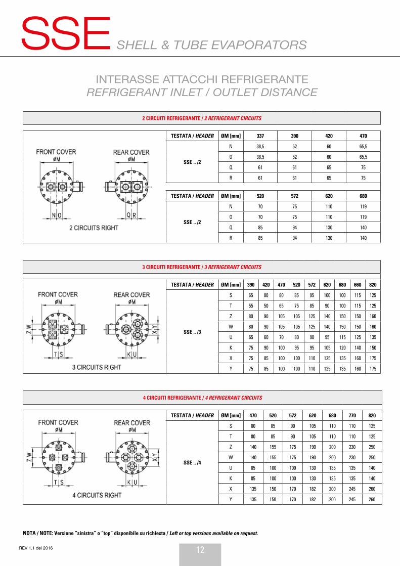
INTERASSE ATTACCHI REFRIGERANTEREFRIGERANT INLET / OUTLET DISTANCE
4 CIRCUITI REFRIGERANTE / 4 REFRIGERANT CIRCUITS
TESTATA / HEADER ØM [mm] 470 520 572 620 680 770 820
SSE .. /4
S 80 85 90 105 110 110 125
T 80 85 90 105 110 110 125
Z 140 155 175 190 200 230 250
W 140 155 175 190 200 230 250
U 85 100 100 130 135 135 140
K 85 100 100 130 135 135 140
X 135 150 170 182 200 245 260
Y 135 150 170 182 200 245 260
2 CIRCUITI REFRIGERANTE / 2 REFRIGERANT CIRCUITS
TESTATA / HEADER ØM [mm] 337 390 420 470
SSE .. /2
N 38,5 52 60 65,5
O 38,5 52 60 65,5
Q 61 61 65 75
R 61 61 65 75
TESTATA / HEADER ØM [mm] 520 572 620 680
SSE .. /2
N 70 75 110 119
O 70 75 110 119
Q 85 94 130 140
R 85 94 130 140
3 CIRCUITI REFRIGERANTE / 3 REFRIGERANT CIRCUITS
TESTATA / HEADER ØM [mm] 390 420 470 520 572 620 680 660 820
SSE .. /3
S 65 80 80 85 95 100 100 115 125
T 55 50 65 75 85 90 100 115 125
Z 80 90 105 105 125 140 150 150 160
W 80 90 105 105 125 140 150 150 160
U 65 60 70 80 90 95 115 125 135
K 75 90 100 95 95 105 120 140 150
X 75 85 100 100 110 125 135 160 175
Y 75 85 100 100 110 125 135 160 175
NOTA / NOTE: Versione “sinistra” o “top” disponibile su richiesta / Left or top versions available on request.
13 REV 1.1 del 2016
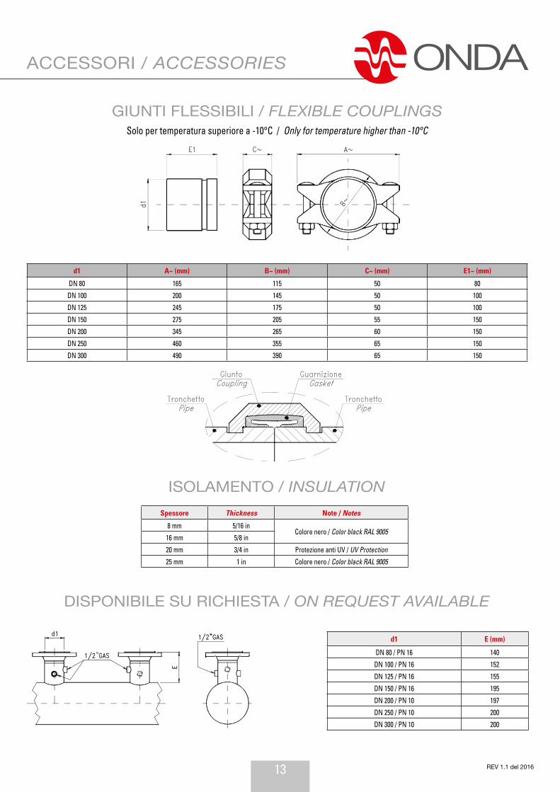
ACCESSORI / ACCESSORIES
GIUNTI FLESSIBILI / FLEXIBLE COUPLINGSSolo per temperatura superiore a -10°C / Only for temperature higher than -10°C
ISOLAMENTO / INSULATION
DISPONIBILE SU RICHIESTA / ON REQUEST AVAILABLE
d1 E (mm)
DN 80 / PN 16 140
DN 100 / PN 16 152
DN 125 / PN 16 155
DN 150 / PN 16 195
DN 200 / PN 10 197
DN 250 / PN 10 200
DN 300 / PN 10 200
d1 A~ (mm) B~ (mm) C~ (mm) E1~ (mm)
DN 80 165 115 50 80
DN 100 200 145 50 100
DN 125 245 175 50 100
DN 150 275 205 55 150
DN 200 345 265 60 150
DN 250 460 355 65 150
DN 300 490 390 65 150
Spessore Thickness Note / Notes
8 mm 5/16 inColore nero / Color black RAL 9005
16 mm 5/8 in
20 mm 3/4 in Protezione anti UV / UV Protection
25 mm 1 in Colore nero / Color black RAL 9005

14REV 1.1 del 2016
NOTE / NOTES

15 REV 1.1 del 2016
GARANZIAA - Onda S.p.A. garantisce l’assenza di vizi e difetti nella lavorazione e nei materiali nei Prodotti per 18 mesi dalla data della consegna.Pertanto ove, durante il periodo di garanzia, i contestati difetti dei Prodotti risultino ogget-tivamente fondati e siano riconosciuti per iscritto da Onda S.p.A., quest’ultima provvederà gratuitamente alla riparazione o, a sua discrezione, alla sostituzione dei Prodotti difettosi, con consegna effettuata franco fabbrica (Ex Works – Incoterms 2000) Stabilimento di Onda S.p.A. in Via Lord Baden Powell, 11 – 36045 Lonigo (VI).
B - Pena di decadenza dalla garanzia, il Cliente dovrà denunziare per iscritto, a mezzo raccomandata con ricevuta di ritorno, i vizi o i difetti riscontrati entro e non oltre 10 (dieci) giorni dal ricevimento dei Prodotti o evidenziati dalla messa in funzione dell’impianto, op-pure, trattandosi di vizi e/o difetti occulti, entro e non oltre 10 (dieci) giorni dalla scoperta degli stessi. In questo caso, l’onere della prova della data della scoperta graverà sul Cliente.
C - Onda S.p.A. garantisce inoltre che i Prodotti sono fabbricati in conformità alle leggi italiane e alle normative comunitarie vigenti alla data di conferma da parte di Onda S.p.A. del relativo ordine del Cliente.Salvo diverso accordo scritto tra le parti, tutte le altre spese accessorie agli interventi di sostituzione e/o di riparazione, saranno a carico e a rischio del Cliente.
D - La garanzia è esclusa qualora i vizi o difetti dei Prodotti siano stati determinati dalle seguenti cause:- Naturale usura e deterioramento.- Riparazioni, manomissioni o modifiche non autorizzate.- Uso e applicazione impropri.- Eccessiva sollecitazione termica, anche occasionale.- Eccessiva sollecitazione elettrica o meccanica.- Mancato rispetto dei parametri funzionali e ambientali indicati da Onda S.p.A. per il corretto impiego e funzionamento dei Prodotti.- Installazione dei Prodotti difforme da quella indicate nelle specifiche tecniche fornite da Onda S.p.A.- Mancata messa a terra dello scambiatore.- Qualsiasi altra causa imputabile a negligenza del Cliente.
E - La garanzia è inoltre esclusa in caso di:- Eventuale non conformità dei Prodotti a normative italiane e/o comunitarie entrate in vigore dopo la data della trasmissione della conferma d’ordine di Onda S.p.A.;- Eventuale non conformità dei Prodotti a leggi e/o normative in vigore nel luogo in cui i Prodotti sono installati e/o assemblati dal Cliente e/o nel luogo di finale utilizzazione dei Prodotti, qualora il Cliente non abbia espressamente richiesto la conformità dei Prodotti a tali leggi e/o normative e non abbia regolarmente informato ONDA S.p.A. del loro contenuto prima della data di trasmissione della conferma d’ordine di quest’ultima. Resta inteso che la presente limitazione si intende efficace anche con riferimento a specifiche normative vigenti in Stati dell’Unione Europea ed applicabili in via autonoma rispetto alle normative comunitarie.
F - Il Cliente non dovrà vendere o commercializzare Prodotti non conformi alle leggi e/o normative indicate nella precedente lettera E. In caso contrario, il Cliente manleverà ONDA S.p.A. da ogni danno e/o perdita dalla stessa sofferto in seguito a contestazioni, sollevate in via giudiziale o stragiudiziale, da qualsiasi soggetto terzo o da pubblica autorità in conseg-uenza della fabbricazione da parte di ONDA S.p.A. di prodotti non conformi alle summenzi-onate leggi e/o normative.
G - Ferma restando l’applicazione del DPR 224/1988, in materia di responsabilità per dan-no da prodotti difettosi, e la responsabilità di Onda S.p.A. in caso di dolo o colpa grave, quest’ultima non sarà in alcun caso responsabile per i danni diretti, indiretti o incidentali che dovessero in qualsiasi modo derivare dalla difettosità dei Prodotti.
WARRANTYA - Onda S.p.A. warrants that the Products shall be free from defects in material and work-manship for a period of 18 months from the date of the delivery.Therefore, should Onda S.p.A., within the warranty period, acknowledge and recognise in writing the existence of the defects in the products and said defects be materially grounded, Onda S.p.A. shall, at its discretion, repair the defective Products at no costs for the Client or replace them by delivering the substitutive products Ex works (Incoterms 2000) at Onda S.p.A.’s premises (Via Lord Baden Powell, 11 – 36045 Lonigo (VI) – Italy).
B - Subject to loss of the warranty, notice of any defect shall be given by the Client in writing with return receipt registered letter within, and not later than, 10 (ten) days from the date of receipt of the products or from the start up of the plant. Subject to loss of the warranty, notice of any latent defect of the Products by the Client shall be given in writing, by return receipt registered letter, within and not later than 10 (ten) days from the date of the relevant discovery. It is hereby understood that the burden of the proof of the date of the discovery shall be borne by the Client.
C - Onda S.p.A. also warrants that the Products are manufactured in compliance with the Italian and European Laws and Regulations in force on the date of the confirmation by Onda S.p.A. of the relevant Client’s order. Unless otherwise expressly agreed in writings by the parties, Client shall bear any other additional expenses related to the operations of repairing or replacing of the defective products.
D - This warranty shall not apply should the defects of the Products be caused by:- Natural wear and tear.- Unauthorised repairs, interventions or modifications.- Unsuited use or application.- Thermal overexposure, also when occasional.- Electrical or mechanical over-stress.- Failure of respecting the functional and environmental parameters suggested by Onda S.p.A. for the correct use and exploitation of the products.- Installation of the products not in compliance with the technical specifications provided by Onda S.p.A.- Missing earth grounding.- Any other cause due to the Client’s negligence.
E - This warranty shall also not apply in case of:- Non compliance of the Products with Italian and European Laws and/or Regulations entered in force after the date of transmission of the order confirmation by Onda S.p.A..- Non compliance of the Products with Laws and/or Regulations in force in the place where the Products are installed and/or assembled by the Client and/or in the place of their final use, should the Client not expressly require the conformity of the Products to said Laws and Regulations and not duly inform Onda S.p.A. of their content before the date of transmission of the latter’s order confirmation. This limitation of the warranty is also applicable with reference to peculiar Laws and Regulations valid and binding in States of the European Union independently of the European Laws and Regulations.
F - The Client shall not sell or market Products not in compliance with the Laws and Reg-ulations mentioned under letter E above. In the negative, the Client shall keep ONDA S.p.A. harmless of any damage or loss suffered by the latter, due to any third party’s and/or au-thority’s claim raised as a consequence of the manufacture by ONDA S.p.A. of Products not in compliance with the above mentioned Laws and Regulations.
G - Without prejudice to the application of DPR 224/1988 on product liability and liability for gross negligence or wilful misconduct, Onda S.p.A. shall never be liable for direct, indirect or occasional damages which in any manner derived from defective products.

Onda France S.A.R.L.320, Avenue Berthelot69008 Lyon Francet. +33 472784606m. +33 608341000www.onda-fr.com [email protected]
Onda USA L.L.C.600 London RdDelaware, OH 43015t. +1 614 321 3342f. +1 614 279 [email protected]
Onda RU Mayakovskogo Street, 18a, Khimki, Moscow Region, Russia 141400 t. +7 495 971 88 53 m. +7 916 676 16 54 www.onda-it.com [email protected]
ONDA (Nanjing) Heat Exchanger Trading Co., Ltd Nanjing Yuhuatai District Yulan Rd. N. 99 Mingfa Commercial Plaza Bld. 1 Office 2498 P.R.China t. +8617712884246 [email protected]
[email protected] www.onda-it.com
PLANT 1 HeadquartersVia Dante Alighieri, 27B36065 Mussolente (VI)Italyt. +39 0424 87633f. +39 0424 578667
PLANT 3Via Vittoria, 158A36065 Mussolente (VI)Italyt. +39 0424 87506f. +39 0424 87744
PLANT 2Via L. Baden Powell, 1136045 Lonigo (VI)Italyt. +39 0444 720720f. +39 0444 720721
ONDA S.p.A.