advanced liquid cooling for a traction drive inverter ... impingement and microfinned enhanced...
TRANSCRIPT

NREL is a national laboratory of the U.S. Department of Energy Office of Energy Efficiency & Renewable Energy Operated by the Alliance for Sustainable Energy, LLC This report is available at no cost from the National Renewable Energy Laboratory (NREL) at www.nrel.gov/publications.
Contract No. DE-AC36-08GO28308
Advanced Liquid Cooling for a Traction Drive Inverter Using Jet Impingement and Microfinned Enhanced Surfaces Preprint S.K. Waye, S. Narumanchi, M. Mihalic, G. Moreno, K. Bennion, and J. Jeffers
Presented at ITherm 2014 Orlando, Florida May 27 – 30, 2014
Conference Paper NREL/CP-5400-61060 August 2014

NOTICE
The submitted manuscript has been offered by an employee of the Alliance for Sustainable Energy, LLC (Alliance), a contractor of the US Government under Contract No. DE-AC36-08GO28308. Accordingly, the US Government and Alliance retain a nonexclusive royalty-free license to publish or reproduce the published form of this contribution, or allow others to do so, for US Government purposes.
This report was prepared as an account of work sponsored by an agency of the United States government. Neither the United States government nor any agency thereof, nor any of their employees, makes any warranty, express or implied, or assumes any legal liability or responsibility for the accuracy, completeness, or usefulness of any information, apparatus, product, or process disclosed, or represents that its use would not infringe privately owned rights. Reference herein to any specific commercial product, process, or service by trade name, trademark, manufacturer, or otherwise does not necessarily constitute or imply its endorsement, recommendation, or favoring by the United States government or any agency thereof. The views and opinions of authors expressed herein do not necessarily state or reflect those of the United States government or any agency thereof.
This report is available at no cost from the National Renewable Energy Laboratory (NREL) at www.nrel.gov/publications.
Available electronically at http://www.osti.gov/scitech
Available for a processing fee to U.S. Department of Energy and its contractors, in paper, from:
U.S. Department of Energy Office of Scientific and Technical Information P.O. Box 62 Oak Ridge, TN 37831-0062 phone: 865.576.8401 fax: 865.576.5728 email: mailto:[email protected]
Available for sale to the public, in paper, from:
U.S. Department of Commerce National Technical Information Service 5285 Port Royal Road Springfield, VA 22161 phone: 800.553.6847 fax: 703.605.6900 email: [email protected] online ordering: http://www.ntis.gov/help/ordermethods.aspx
Cover Photos: (left to right) photo by Pat Corkery, NREL 16416, photo from SunEdison, NREL 17423, photo by Pat Corkery, NREL 16560, photo by Dennis Schroeder, NREL 17613, photo by Dean Armstrong, NREL 17436, photo by Pat Corkery, NREL 17721.
NREL prints on paper that contains recycled content.

1
This report is available at no cost from the National Renewable Energy Laboratory (NREL) at www.nrel.gov/publications.
Advanced Liquid Cooling for a Traction Drive Inverter Using Jet Impingement and Microfinned Enhanced Surfaces
Scot K. Waye, Sreekant Narumanchi, Mark Mihalic, Gilbert Moreno, Kevin Bennion, Jana Jeffers
National Renewable Energy Laboratory 15013 Denver West Parkway
Golden, Colorado 80401 Email: [email protected]
ABSTRACT
This study evaluates a jet impingement based cooling strategy combined with microfinned enhanced surfaces as a means of improving thermal management for power electronic devices. For comparison, a baseline channel flow heat exchanger and jet impingement on plain surfaces are characterized. The jets, augmented with enhanced microfinned surfaces, provide localized cooling to areas heated by the insulated-gate bipolar transistors and diode devices. Lighter materials and simpler manufacturing while managing required pumping power increase the overall performance while reducing weight, volume, and cost. Computational fluid dynamics modeling validated by experiments was used to characterize the baseline as well as jet-impingement-based heat exchangers at typical automotive flow rates using a 50%–50% mixture by volume of water and ethylene glycol. The three cooling configurations were tested at full inverter power (40 to 100 kW output power) on a dynamometer. An increased thermal performance was observed for the jet-impingement configurations. Experiments were also performed to investigate the long-term reliability of the jets impinging on enhanced surfaces.
KEY WORDS: jet-impingement, enhanced surfaces, microfinned surfaces, single-phase liquid cooling, power electronics, inverter thermal management, heat transfer
NOMENCLATURE CFD computational fluid dynamics DBA direct-bond-aluminum DBC direct-bond-copper IGBT insulated gate bipolar transistor P pressure, Pa Q heat, W R resistance, K/W T temperature, K or ºC V volumetric flow rate WEG water-ethylene glycol coolant
Subscripts avg average hx heat exchanger j junction j-l junction to liquid coolant l liquid coolant max maximum th thermal
INTRODUCTION With the increasing trend towards miniaturization and
advancements in devices, thermal management of power electronics is becoming more challenging. With more power passing through smaller areas, the heat flux increases and necessitates more aggressive cooling to maintain device operational temperatures. Reducing the component costs and allowing for increased power density and specific power are key objectives of the U.S. Department of Energy’s Advanced Power Electronics and Electric Motors Program. The program targets are intended to increase market penetration of hybrid-electric and all-electric vehicles.
The objective of this work is to design, develop, characterize, and demonstrate a light-weight, low-cost, inverter-scale (based on a commercially available inverter), single-phase liquid-cooled heat exchanger that is a significant improvement over conventional channel-flow-based heat exchangers. The purpose is to use a conventional coolant (water-ethylene glycol [WEG]) to maintain existing cooling architecture while improving thermal management of the inverter.
In previous work, we developed a first prototype [1] that showed promising thermal improvements using a submerged liquid jet-impingement array, but with an increase in the pumping power. A second prototype was designed, fabricated, and tested. The results from this second prototype will be compared to the first jet-based prototype as well as the baseline channel flow configuration.
General studies of single-phase liquid jets are extensive in the literature [2-5], including experimental, theoretical, and numerical approaches. Different configurations of impinging jets have been studied, including single free-surface jets [6], multiple free-surface jets [7-10], single submerged jets [6, 11, 12], multiple submerged jets [7, 10, 11, 13], and confined single submerged jets [4, 14-16]. Both planar and circular jets have been studied.
For power electronics cooling applications, a large number of experimental correlations have been developed for the local and average heat transfer coefficients for impinging jets on the surface of a simulated chip [3-5], usually 10-mm by 10-mm or 12.7–mm by 12.7-mm in area. Further parametric and optimization study examined potential improvements [17]. Ndao et al. [18] compare single and multiple submerged jet-impingement cooling strategies for electronics cooling with other technologies such as parallel micro-channel, in-line and staggered circular pin-fin, and offset strip-fin heat exchangers. Jet impingement combined with a mini-channel heat exchanger or flows through narrow gaps has also been investigated [19, 20]. Skuriat and Johnson [21] discuss direct

2
This report is available at no cost from the National Renewable Energy Laboratory (NREL) at www.nrel.gov/publications.
cooling on an aluminum nitride substrate with two insulated gate bipolar transistors (IGBTs) and two diode dies. Of high interest is cooling of wide band-gap devices, including gallium nitride devices, because maximum junction temperatures can be higher than silicon devices, and this was recently examined by Bhunia et al. [22].
Air jets have also been studied extensively [11]. Some of the non-dimensional heat transfer correlations developed from studies on air jets [11] can also be applied to liquid jets. Researchers have explored the impact of a vast array of parameters such as jet velocity, jet diameter, impact angle, nozzle-to-chip spacing, nozzle-to-nozzle spacing, turbulence levels, nozzle shapes, nozzle length, jet pulsations, jet confinement, chip-surface enhancement, and fluid properties on the chip-surface heat transfer coefficients. All these are covered in detail in comprehensive reviews and studies on liquid and air jets [2, 3, 4, 11, 23].
Moreover, studies have demonstrated that jet impingement heat transfer can be further enhanced through the use of surface roughening techniques for both liquid and air jets [24-27]. Moreno et al. [28] showed superior performance of submerged jets impinging on a microfinned enhanced surface. These results were noteworthy because submerged/flooded jet configuration is a more practical application than free jets [29, 30].
In automotive power electronics, it is important to reduce cost, increase power density and specific power to help make electric-drive vehicles more cost-effective and increase their market acceptance and penetration. Traditionally, channel flow-based cold plates using a WEG mixture (50%–50% by volume) are used in a majority of hybrid electric vehicles for cooling power electronics components [29].
This work focuses on using existing liquid coolant (WEG) loops with improved cooling technologies on the inverter scale. Through experiments and numerical modeling, we investigate submerged liquid jet impingement on plain and enhanced surfaces. By modeling the system and validating the model with low-power experiments, we predict the thermal performance of a full inverter-scale system. We also test the inverter at full power conditions using a dynamometer with full switching controls. We conduct a few fundamental reliability tests in order to investigate potential concerns of clogged jets and surface degradation over time.
APPROACH Design and Fabrication
Building on lessons learned from the first prototype fabrication and testing [1], a second prototype heat exchanger utilizing a submerged jet-impingement cooling approach and a light-weight plastic material was fabricated. The main differences of this prototype from the first are the material and manufacturing process and the flow path. The first prototype was fabricated using a selective-laser-sintering rapid prototyping process using automotive-grade glass-fiber-reinforced nylon plastic. The second prototype was machined from Delrin, a high-temperature plastic, although this component could be injection molded from a variety of high-temperature plastics.
The first prototype replaced the channel flow configuration with jets that impinge on the module surfaces. The flow path remained similar to that of the baseline design. The jets increased the overall pressure drop, so the second prototype, shown in Fig. 1, removed unnecessary flow path to reduce the pressure drop back to levels similar to the channel-flow baseline. The first prototype used screwed in nozzles while the second prototype implemented plates with drilled holes serving as nozzles. The nozzles are 1.4 mm in diameter. Note eight nozzles in each nozzle plate. Each power module contains 8 diodes and 8 IGBTs. Each nozzle is located nearly under the center of a diode or IGBT. Parts of the manifold have been omitted from fabrication for ease of testing. The jet impingement cooling approach eliminates the use of thermal interface material between the base plate and the heat sink/cold plate and therefore is expected to improve thermal performance. Further details on the previous design are discussed by Narumanchi [31].
Fig. 1 Second light-weight, inverter-scale plastic heat
exchanger prototype. Schematic of one of three power modules overlaid with location of thermocouples (embedded in base plate) for full inverter testing.
Experiments Three half bridge power modules, fabricated by PowerEx,
were used in all testing. Low power testing. Experiments were conducted to
characterize the performance of the new heat exchanger (Fig. 2). In these tests, four diodes on the center module were powered with approximately 105W.
Previous experiments characterized the first prototype as well as the baseline channel-flow-based aluminum heat exchanger [31]. The tests were carried out using WEG (50%–50% mixture by volume) as the coolant at a temperature of 70°C. A typical industry flow rate of 1.67x10⁻⁴ m3/s (10 L/min) as well as 3.34x10⁻⁵, 8.35x10⁻⁵, and 1.34x10⁻⁴ m3/s (2, 5, and 8 L/min) were examined for the various heat exchangers. Using 70ºC WEG (50%–50% by volume), these flow rates correspond to jet Reynolds number values based on nozzle diameter of approximately 500, 1,250, 2,000, and 2,500 for the four flow rates. The average temperature of the diodes was measured using a transient thermal tester. Based on the information of diode junction temperature as well as the total power dissipated in the diodes, the total thermal resistance was computed.
Inlet
Flow path
Nozzle
Electrical connections
Thermocouple locations
Outlet

3
This report is available at no cost from the National Renewable Energy Laboratory (NREL) at www.nrel.gov/publications.
Fig. 2 Second prototype testing on the WEG loop.
Fig. 3 Wolverine Tube MicroCool finned surface technology
on module (top left) and close-up (top right and bottom).
Two sets of modules were used on the second prototype testing. The first set had standard plain copper base plates. The second set had microfinned surface enhancement located under each IGBT/diode pair, as seen in Fig. 3, with a close-up
of the microfinned surface. The microfinned surface was created by skiving copper base plate, neither adding nor removing material. The increase in surface area is estimated to be approximately eleven times the plain surface. The microfins were approximately 100 µm wide and added approximately 200 µm to the base plate (the space between fins is cut into the original surface).
Full inverter testing. Full-scale inverter testing was conducted on a dynamometer at UQM Technologies Inc. Three configurations were run: channel flow with plain surfaces, jet impingement with plain surfaces, and jet impingement with microfinned enhanced surfaces, as seen in Fig. 4. The tests were run at power levels of 40, 60, 80, and 100 kW inverter power at set points of 360 V and 2,000 rpm. A 40%–60% water-ethylene glycol (by volume) coolant flowing at 30ºC and 10 L/min was used.
Fig. 4 Full power inverter testing on dynamometer (channel
flow with plain modules configuration shown).
Two k-type thermocouples on each module were inserted into the mid-point of the copper base plate nearly centered under the IGBT/diode pair, as shown in Fig. 5 and Fig. 6, and centered above the microfinned surface when applicable. Note the difference in locations of the thermocouples relative to the cooling path. For the channel flow configuration, the thermocouples are not located near aluminum wall-fluid interfaces. For the jet configuration, the thermocouples are located nearly between two jets, each centered on the device above. At equilibrium, these thermocouple temperatures, the inlet and outlet coolant temperatures, and ambient temperature were recorded.
The average coolant temperature (inlet to outlet) was subtracted from the average thermocouple temperature to yield a temperature difference to compare thermal performance. Although an estimate of the heat dissipated by the devices could be calculated using the fluid thermal properties and temperature rise in the coolant, it is not very accurate as there could be other heat dissipation pathways in the inverter. We assumed that the heat dissipated by the devices at each power level is the same for each configuration since the comparison between configurations is the main metric being examined.
4
This report is available at no cost from the National Renewable Energy Laboratory (NREL) at www.nrel.gov/publications.
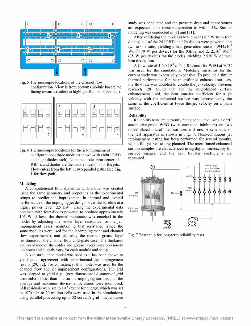
Fig. 5 Thermocouple locations of the channel flow
configuration. View is from bottom (module base plate facing towards reader) to highlight fluid path (shaded).
Fig. 6 Thermocouple locations for the jet-impingement
configurations (three modules shown with eight IGBTs and eight diodes each). Note the circles near center of IGBTs and diodes are the nozzle locations for the jets. Flow enters from the left in two parallel paths (see Fig. 1 for flow path).
Modeling A computational fluid dynamics CFD model was created
using the same geometry and properties as the experimental setups to predict the improvement in thermal and overall performance of the impinging jet designs over the baseline at a higher power level (2.5 kW). Using the experimental data obtained with four diodes powered to produce approximately 105 W of heat, the thermal resistance was matched in the model by adjusting the solder layer resistance for the jet-impingement cases, maintaining that resistance (since the same modules were used for the jet-impingement and channel flow experiments), and adjusting the thermal grease layer resistance for the channel flow cold-plate case. The thickness and resistance of the solder and grease layers were previously unknown and slightly vary for each module and setup.
A k-ω turbulence model was used as it has been shown to yield good agreement with experimental jet impingement results [29, 32]. For consistency, this model was used for the channel flow and jet impingement configurations. The grid was adapted to yield a y+ (non-dimensional distance of grid centroids) of less than one on the impinging surface, and the average and maximum device temperatures were monitored. (All residuals were set to 10-3 except for energy, which was set to 10-6). Up to 20 million cells were used in the simulations, using parallel processing up to 32 cores. A grid independence
study was conducted and the pressure drop and temperatures are expected to be mesh-independent to within 5%. Similar modeling was conducted in [1] and [31].
After validating the model at low power (105 W from four diodes), all of the 24 IGBTs and 24 diodes were powered at a two-to-one ratio, yielding a heat generation rate of 1.944x10⁹ W/m3 (70 W per device) for the IGBTs and 2.12x10⁹ W/m3 (35 W per device) for the diodes, yielding 2,520 W of total heat dissipation.
A flow rate of 1.67x10⁻⁴ m3/s (10 L/min) for WEG at 70°C was used for the simulations. Modeling microfins for the current study was excessively expensive. To produce a similar thermal performance for the microfinned enhanced surfaces, the flow rate was doubled to double the jet velocity. Previous research [28] found that for the microfinned surface enhancement used, the heat transfer coefficient for a jet velocity with the enhanced surface was approximately the same as the coefficient at twice the jet velocity on a plain surface.
Reliability Reliability tests are currently being conducted using a 65°C
automotive-grade WEG (with corrosion inhibitors) on two nickel-plated microfinned surfaces at 5 m/s. A schematic of the test apparatus is shown in Fig. 7. Near-continuous jet impingement testing has been performed for several months, with a full year of testing planned. The microfinned enhanced surface samples are characterized using digital microscopy for surface images, and the heat transfer coefficients are measured.
Fig. 7 Test setup for long-term reliability tests.

5
This report is available at no cost from the National Renewable Energy Laboratory (NREL) at www.nrel.gov/publications.
Table 1. Thermal resistance based on four powered diodes, Rth,j-l [K/W], and improvement over channel flow heat exchanger for 8 L/min and 10 L/min: (1) designates first prototype, (2) designates the second prototype.
RESULTS AND DISCUSSION
Low Power Experimentation Experimentation using a transient thermal tester (T3ster)
yields structure functions that provide information on the thermal capacitance and the thermal resistance. This information can be used to differentiate the thermal resistance of the passive stack and the cooling technology. By mapping all the resistances for various flow rates and cooling technologies (channel flow cold plate, impingement on plain surfaces, impingement on enhanced surfaces), the point where they diverge indicates the boundary between the passive stack in the module and the convective cooling technology. A map of thermal resistance for various heat exchanger configurations at 1.67x10⁻⁴ m3/s (10 L/min) are given in Fig. 8. In the case of the channel flow, the cold plate layer is included in the convective cooling technology as it is omitted for the impinging jet configurations. For the modules used in this testing, the thermal resistance of the passive stack was approximately 0.09 K/W under the condition of four diodes being powered.
Fig. 8 Thermal resistance map from T3ster for thermal
response of four powered diodes.
For 1.34x10⁻⁴ m3/s and 1.67x10⁻⁴ m3/s flow rates (8 L/min and 10 L/min), the junction to liquid thermal resistances (Rth,j-l [K/W]) and percent reduction as compared to the baseline channel flow cold plate are provided in Table 1. Uncertainty in the resistance values were ±0.001 K/W and in the percent reduction were ±1%. The test cases included the channel flow, the first prototype jet-impingement heat exchanger with plain
surfaces, and the second prototype jet-impingement heat exchanger with plain and microfinned enhanced surfaces.
The thermal performance for the first and second prototypes with jets impinging on plain surfaces was nearly the same, which was expected because the jet design was essentially the same for both cases. For the jet impingement on a plain surface, the thermal resistance was reduced by 5.1% as compared with the performance of the baseline channel flow heat exchanger. On the microfinned surface, the reduction was 10.3% at the nominally designed target distance (0.5 mm).
The resistance of the passive stack was estimated to be approximately 0.09 K/W. By subtracting this resistance from the total resistance, the convective resistance (the resistance from the solid-to-fluid), Rth,hx [K/W], was 15.2% lower for jet impingement on plain surfaces, and 37.0% lower for jet impingement on enhanced surfaces, both with respect to the baseline system. Additional reduction to the junction-to-liquid resistance can be achieved by more aggressive cooling strategies or reducing the resistance in the passive stack.
For the jet-impingement heat exchangers, the nozzle-to-base plate distance (target distance) was also examined. The nominal target distance was 0.5 mm. Offsets of 1.45 mm and 3.25 mm were introduced to examine the effect of increased distance between the nozzle and surface. For the microfinned enhanced surface, the microfins extended approximately 200 µm into the flow, reducing the jet length to 1.75 mm and 3.55 mm with the two offsets, respectively.
Increased distance between the nozzle and the target reduces the submerged jet momentum. The interaction of the jet with the surface to create a thin boundary layer and turbulence are important aspects to transfer the heat from the solid to the fluid. For very low velocities (flow rate) and large target distances, the momentum of the jet decreases and the jet core spreads, decreasing heat transfer on the surface. For the plain surface, this leads to reduced heat transfer. For the microfinned surface, the interaction between the jet and the increased surface area over which it impinges is slightly increased, which helps increase the heat transfer. This effect is reduced with further distance since the jet is weakened further. For enhanced surfaces, there is an optimal distance depending on the jet characteristics.
Table 2 shows the experimental pressure drop across the heat exchanger configurations at 1.34x10⁻⁴ and 1.67x10⁻⁴ m3/s (8 and 10 L/min). As previously discussed, the first prototype had a large increase in pressure loss due to the introduction of the jets. By removing unnecessary flow path in the second prototype, the pressure loss was closer to the baseline channel
Channel Flow Jet/Plain (1) Jet/Plain (2) Jet/Microfinned (2) Target distance (mm) N/A 0.5 0.5 1.95 0.3 1.75 3.55
Resistance, Rth,j-l [K/W] 1.34x10⁻⁴ m3/s (8 L/min) 0.139 0.136 0.143 0.126 0.126 0.128 1.67x10⁻⁴ m3/s (10 L/min) 0.136 0.128 0.129 0.136 0.122 0.119 0.122
Improvement over baseline 1.34x10⁻⁴ m3/s (8 L/min) 2.2% -2.9% 9.4% 9.4% 7.9% 1.67x10⁻⁴ m3/s (10 L/min) 5.9% 5.1% 0.0% 10.3% 12.5% 10.3%

6
This report is available at no cost from the National Renewable Energy Laboratory (NREL) at www.nrel.gov/publications.
flow heat exchanger. Therefore, the improvement in the coefficient of performance, defined as the inverse product of the resistance and pumping power (1/RthΔPV), was nearly the same for the jet impingement on the plain surface heat exchanger and 13% better for the jet impingement on the microfinned surfaces heat exchanger.
Table 2. Experimental pressure drop [Pa] across heat exchanger. (1) denotes first prototype, (2) denotes second prototype. Nozzle diameter 1.4 mm (48 nozzles).
Flow Rate [m3/s] (L/min) 1.34x10⁻⁴ (8) 1.67x10⁻⁴ (10) Channel Flow 12,686 19,598 Jet/Plain (1) 24,407 Jet/Plain (2) 13,221 20,581 Jet/Microfinned (2) 12,755 19,995
Heat Exchanger Modeling The focus of the modeling was for an IGBT-to-diode
power ratio of two to one and a total heat generation of 2,520 W. Flow rates, pressure drops, average and maximum temperatures, and junction to liquid thermal resistances based on the respective temperatures are given in Table 3.
The thermal resistance for the jet-impingement heat exchanger was reduced by 9% and 32% for the plain and microfinned surfaces, respectively. These improvements translated to reductions in the average and maximum temperatures of approximately 5°C (Fig. 9) and 15°C for the plain and microfinned surfaces with jet impingement, respectively, as compared to the baseline heat exchanger.
The reductions in thermal resistance from the inverter power modeling can be considered an idealized situation yielding the highest potential improvement in thermal performance. In the experiments, some heat from the devices goes into the module packaging and inverter case, so not all heat transfers to the coolant. Therefore, the thermal resistance is artificially reduced (Rth,j-l = ΔT/Q). Validation of the model assumed that all heat transferred to coolant. The geometry in the model included up to the device (no module casing), with boundary conditions on external faces being adiabatic.
The localized and directed cooling from impinging jets creates high local heat transfer coefficients where the heat flux is the highest, under the devices, as shown in Fig. 10.
The thermal resistance is subject to the convective cooling resistance, which relies on the cooling strategy or technology, and the heat flux magnitude and distribution. As the heat seeks the path of least resistance, either due to a low convective cooling resistance at the solid-fluid interface or the absence of multiple heat generating devices, it will manifest as a lower thermal resistance due to reduced heat spreading. The low power test only heated four diodes while the full model heats all diodes and IGBTs.
Using basic analytical equations for device losses, the increase in potential power can be calculated from the increased heat dissipated due to the decreased thermal resistance. The specific power increased 29% and 55%, and power density increased 6% and 28% over the baseline for the plain and microfinned surfaces with jet impingement, respectively. The coefficient of performance improved by up to 5% and 40%, respectively.
A 9% decrease in thermal resistance allows for 10% more heat to be dissipated. Using the same analytical equations mentioned before, this correlates to an approximate 6% increase in power per device area, or a 6% decrease in device area per power by varying only the current. Therefore, 6% of the device area (such as silicon) or number of devices could theoretically be removed, creating a cost savings. Similarly, a 32% decrease in thermal resistance translates to an approximate device area reduction of 22%.
Fig. 9 Temperatures of modules for baseline (top) and jet impingement on the plain surface for the first prototype (bottom). The second prototype has similar thermal performance.
Fig. 10 Heat transfer coefficient at the solid-fluid interface for baseline (top) and jet impingement on the plain surface of the first prototype (bottom). The second prototype has similar thermal performance.

7
This report is available at no cost from the National Renewable Energy Laboratory (NREL) at www.nrel.gov/publications.
Table 3. Thermal resistance and device temperatures for modeled heat exchangers. (Rth,j-l = (Tdevices-Tcoolant)/Q, where Tcoolant is 70ºC [343.2 K] and Q is 2,520 W). *Flow rate doubled to match heat transfer coefficient of microfinned enhanced surface.
Full Inverter Experimentation Information provided by the UQM Technologies Inc., who
supplied the baseline inverter and conducted the dynamometer testing, estimated several outputs using a model that they have developed. For the inverter power levels (output shaft power) of 40, 60, 80, and 100 kW, the heat dissipated (losses) were estimated to be 0.9, 1.3, 1.6, and 2.2 kW. For comparison, by using the mass flow rate, the specific heat, and the inlet-outlet coolant temperature difference, the heat dissipated was estimated to be 0.9, 1.2, 1.7, and 1.9 kW, respectively, an estimate expected to be low since all the heat is not transferred to the liquid coolant. The estimated junction temperatures of the IGBTs and diodes at the four power levels for the baseline inverter from their model are shown in Table 4. Recall that the coolant temperature for these tests was 30ºC. The model that predicts these values has an estimated 15% uncertainty.
Table 4. Predicted IGBT and diode junction temperatures [ºC].
Power [kW] 40 60 80 100 IGBT 46.6 54.5 62.2 73.2 Diode 47.7 52.6 56.3 64.1 Average 47.2 53.6 59.3 68.7
The average measured temperatures at the thermocouple locations are given in Table 5. The agreement with the model is relatively close, although the measured temperatures overall are lower than modeling results because the location of the thermocouples is in the base plate rather than at the device junction.
Table 5. Average thermocouple temperatures for three configurations [ºC].
Power [kW] 40 60 80 100 Channel, Plain 46.6 52.5 60.2 68.7 Jet, Plain 53.5 60.0 67.6 Jet, Microfinned 44.8 50.2 56.1 62.3
The thermocouple locations caused a greater variation in temperatures for the channel flow configuration than the jet impingement configurations, as seen in Fig. 11. For the impinging jets, the temperatures (±0.8ºC) for thermocouples 1, 3, and 5 are generally slightly higher than thermocouples 2, 4, and 6, indicating that the flow through the flow paths with thermocouples 2, 4, and 6 is likely higher than for 1, 3, 5 (higher flow rate equates to a higher jet velocity and heat transfer coefficient).
Fig. 11 Thermocouple (TC) temperatures for channel flow
with plain modules and jet impingement with microfinned modules.
The temperature reading for the channel flow configuration was more dependent on the location of the thermocouple relative to the channel flow path. As seen in Fig. 5, the thermocouples were located nearly above solid-fluid interfaces of the coolant flow paths. Each jet provides nearly the same jet velocity and coolant temperature, whereas the coolant in the channel flow varies along the parallel and serial paths. This temperature variation between the hottest and coldest thermocouple temperature measurement is shown in Table 6. The jet configuration provides more temperature uniformity in the system than the channel flow configuration, thus cooling devices more equally.
Table 6. Temperature variation [ºC] (isothermality) between hottest and coldest thermocouple temperatures.
Power [kW] 40 60 80 100 Channel, Plain 7.7 11.2 14.3 15.8 Jet, Plain 7.6 10.0 12.3 Jet, Microfinned 4.3 5.9 7.2 9.8
The local cooling afforded by the jets is one advantage to the technology, as the highest cooling is located near the highest heat flux and temperature. This provides for a more uniform temperature distribution among the various devices whereas for the channel flow technology, some devices are hotter than others. In the channel flow heat exchanger, the heat is spread by the additional cold plate layer and then is removed by the fluid. Thus, more conduction (and thermal
Flow rate [m3/s] (L/min)
∆P [Pa]
Tavg,devices [K]
Rth,j-l [K/W]
Tmax,devices [K]
Rth,j-l [K/W]
Channel Flow Cold Plate 1.67x10⁻⁴ (10) 17,891 391.6 0.0192 395.8 0.0209 Jet/Plain (1) 1.67x10⁻⁴ (10) 20,800 386.7 0.0173 390.6 0.0188 Jet/Microfinned (1) 3.34x10⁻⁴ (20)* 376.6 0.0132 380.1 0.0147 Jet/Plain (2) 1.67x10⁻⁴ (10) 18,732 387.2 0.0174 391.2 0.0190 Jet/Microfinned (2) 3.34x10⁻⁴ (20)* 376.2 0.0131 380.2 0.0147

8
This report is available at no cost from the National Renewable Energy Laboratory (NREL) at www.nrel.gov/publications.
resistance) is present. The localized cooling from the jets eliminates the need for the additional spreading. However, the time constant for the heat transfer is decreased, so care should be exercised to account for thermal transient effects on the instantaneous junction temperature tolerance of the power electronic devices.
From previous experiments and modeling, the jet-impingement configurations were expected to have lower junction temperatures for the same power level as compared to the channel flow configuration. For the full inverter testing, the difference (±1.5ºC) between thermocouple (±0.8ºC) and coolant temperatures (±1.2ºC) did decrease for the jet impingement with microfinned surfaces configuration, but remained nearly the same for the jet impingement with plain surfaces configuration, as seen in Fig. 12.
Fig. 12 Temperature difference between average thermocouple
and average coolant temperatures.
The location of the thermocouples also affects the perceived reduction in temperature between the various configurations. They are located near, but not at the hottest spot or highest heat flux area. They are also somewhat insulated by additional thermal resistance due to thermal grease between the modules and cold plate that is used to create a more uniform thermal path. The thermocouples are at discrete points. It would be ideal to have temperature sensors/measurements at each device junction.
Because the thermocouples are embedded in the middle of the module base plate, the difference in temperatures between the thermocouples and the coolant represents a thermal resistance greater than just the convective resistance and less than the total resistance including the stack.
Using the inverter model, we obtained the virtual temperature difference between the thermocouple locations and the coolant. Using these temperature differences to obtain the a comparison of thermal performance between the baseline and jet impingement configurations yielded very similar reductions to those obtained from comparing the temperature differences using the average or maximum device temperatures.
When comparing the thermal performance of the jet impingement with a plain module configuration to the baseline channel flow at full inverter power (all devices powered), we
observed only a slight improvement in the reduction of the temperature difference between the thermocouples and the coolant: just -3.4%, 1.2%, 3.6%, and 1.5% for 40, 60, 80, and 100 kW power levels, respectively (Fig. 13). Adding the microfinned enhanced surfaces reduced the temperature difference by 6.5%, 14.2%, 16.2%, and 16.5% for 40, 60, 80, and 100 kW power levels, respectively. At 100 kW, the uncertainty in this reduction was ±6.1%. The reduction in the temperature difference is directly proportional to the reduction in thermal resistance.
Fig. 13 Reduction in temperature difference from baseline
channel flow to jet impingement configurations.
Using the reduction in temperature difference and pressure drop across the heat exchanger, the improvement in the coefficient of performance is given in Table 7. Similar to the analysis conducted with the modeling, the increase in specific power [kW/kg] and power density [kW/L] is also given.
Table 7. Improvement in coefficient of performance, specific power, and power density over baseline channel flow.
Power [kW] 40 60 80 100 Coefficient of performance
Jet, Plain -28.5% -0.8% 1.7% -0.5% Jet, Microfinned 4.8% 14.2% 17.0% 17.4%
Specific Power Jet, Plain 15.8% 20.1% 22.5% 21.1% Jet, Microfinned 26.4% 33.6% 35.6% 35.9%
Power Density Jet, Plain -4.5% -0.9% 1.1% -0.1% Jet, Microfinned 4.3% 10.2% 11.9% 12.1%
Reliability Over four months of reliability experimental observations
are available for this work. After 60 and 120 days, the microfinned surface samples were examined for defects and thermal conductivity. After an initial break in period, the thermal conductivity has remained relatively steady (Fig. 14). There is no clogging or change in diameter of the nozzles.

9
This report is available at no cost from the National Renewable Energy Laboratory (NREL) at www.nrel.gov/publications.
Fig. 14 Heat transfer coefficients of microfinned enhanced
surface samples subject to jet impingement.
CONCLUSIONS A light-weight inverter-level heat exchanger tested at
inverter power (40-100 kW) using liquid jet impingement and microfinned enhanced surfaces showed improved thermal performance by up to 17% when compared to a channel flow design. Along with a weight reduction of approximately 3 kg, the specific power (kW/kg) is improved by up to 36% and power density (kW/L) by 12% over the baseline channel flow heat exchanger. Jet impingement on plain surfaces yielded a slight thermal performance improvement (3%) over the baseline.
Experiments at low power (105 W) demonstrated that the thermal resistance is reduced 5% to 13% with plain and microfinned enhanced surfaces, respectively, compared to the baseline heat exchanger. The base plate-to-coolant (convective) resistance was reduced by up to 37% for the jet-based configuration as compared to the baseline, suggesting that while improvements to the cooling side reduce the overall resistance, efforts to reduce the passive stack resistance may also greatly contribute to lowering the overall junction-to-coolant resistance.
CFD modeling at inverter power, resulting in 2.5 kW of heat dissipation predicted a thermal resistance reduction of 9% and 32% for the plain and microfinned-enhanced surfaces, respectively. The modeling represents an idealized limit if all heat from the devices was transferred to the coolant.
Fabrication of the heat exchanger out of light-weight plastic may provide additional cost savings associated with inexpensive materials and cost-effective manufacturing techniques. The cost of surface enhancement must be weighed. Effective reliable sealing between the modules and the heat exchanger is also vital.
Experiments were conducted to evaluate the reliability of the microfinned enhanced surfaces when subjected to near-continuous impinging WEG jets. Testing is ongoing, but after an initial break-in period, the nozzles and the nickel-plated enhanced surfaces have not degraded.
ACKNOWLEDGMENTS The authors would like to acknowledge the support
provided by Susan Rogers and Steven Boyd, Technology Development Managers for Advanced Power Electronics and Electric Motors, Vehicle Technologies Office, U.S. Department of Energy Office of Energy Efficiency and Renewable Energy. The authors thank Titus Herschberger (UQM Technologies Inc.) for full-inverter testing of three configurations. The authors would also like to acknowledge Jon Lutz (UQM Technologies Inc.) for providing very useful information on the UQM inverter, Sy-Jenq Loong (Wolverine Tube Inc.) for providing microfinned surface enhancements, as well as Ralph Taylor (Delphi) for providing the DBA/DBC substrates.
REFERENCES [1] S. Narumanchi, M. Mihalic, G. Moreno and K. Bennion,
"Design of Light-Weight, Single-Phase Liquid-Cooled Heat Exchanger for Power Electronics," in 13th IEEE Intersociety Conference on Thermal and Thermomechanical Phenomena in Electric Systems, San Diego, 2012.
[2] B. Webb and C.-F. Ma, "Single-phase liquid jet impingement heat transfer," Advances in Heat Transfer, vol. 26, pp. 105-217, 1995.
[3] J. Lienhard, "Liquid jet impingement," Annual Review of Heat Transfer, pp. 199-270, 1995.
[4] S. Garimella, "Heat transfer and flow fields in confined jet impingement," Annual Review of Heat Transfer, pp. 413-494, 2000.
[5] S. Narumanchi, C. Amon and J. Murthy, "Influence of pulsating submerged liquid jets on chip-level thermal phenomena," ASME Journal of Electronic Packing, vol. 125, pp. 354-361, 2003.
[6] D. Womac, S. Ramadhyani and F. Incropera, "Correlation equations for impingement cooling of small heat sources with single circular liquid jets," ASME Journal of Heat Transfer, vol. 116, pp. 482-486, 1994.
[7] D. Womac and F. R. S. Incropera, "Correlating equations for impingement cooling of small heat sources with multiple circular liquid jets," ASME Jormal of Heat Transfer, vol. 116, pp. 482-486, 1994.
[8] Y. Pan and B. Webb, "Heat transfer characteristics of arrays of free-surface liquid jets," General Papers in Heat and Mass Transfer, Insulation and Turbomachinery, vol. 271, pp. 23-28, 1994.
[9] N. Yonehara and I. Ito, "Cooling characteristics of impinging multiple water jets on a horizontal plane," Technical Report - Kansai University, 1982.
[10] A. Robinson and E. Schnitzler, "An experimental investigation of free and submerged miniature liquid jet array impingement heat transfer," Experimental Thermal and Fluid Science, vol. 32, pp. 1-13, 2007.
[11] H. Martin, "Heat and mass transfer between impinging gas jets and solid surfaces," Advances in Heat Transfer, vol. 13, pp. 1-60, 1977.

10
This report is available at no cost from the National Renewable Energy Laboratory (NREL) at www.nrel.gov/publications.
[12] D. Wadsworth and I. Mudawar, "Cooling of a multichip electronic codule by means of confined two-dimensional jets of dielectric liquid," ASME Journal of Heat Transfer, vol. 112, pp. 891-898, 1990.
[13] Z. Wang, T. Wong, F. Duan, K. Toh, K. Choo, S. Tan, C. Loh and S. Yeo, "Submerged liquid jet impingement cooling," in 2011 IEEE 13th Electronics Packaging Technology Conference, Singapore, 2011.
[14] S. Garimella and R. Rice, "Confined and submerged liquid jet impingement heat transfer," ASME Journal of Heat Transfer, vol. 117, pp. 871-877, 1995.
[15] S. Garimella and B. Nenaydykh, "Nozzle-geometry effects in liquid jet impingement heat transfer," International Journal of Heat and Mass Transfer, vol. 39, no. 14, pp. 2915-2923, 1996.
[16] C. Li and S. Garimella, "Prandtl-number effects and generalized correlations for confined and submerged jet impingement," International Journal of Heat and Mass Transfer, vol. 44, pp. 3471-3480, 2001.
[17] P. Panda, S. Ekkad and K. Ngo, "Impingement-based high performance cooling configurations for automotive power converters," International Journal of Heat and Mass Transfer, vol. 55, no. 4, pp. 834-847, 2012.
[18] S. Ndao, Y. Peles and M. Jensen, "Multi-objective thermal design optimization and comparative analysis of electronics cooling technologies," International Journal of Heat and Mass Transfer, vol. 52, pp. 4317-4326, 2009.
[19] J. Bintoro, A. Akbarzadeh and M. Mochizuki, "A closed-loop electronics cooling by implementing single phase impinging jet and mini channels heat exchanger," Applied Thermal Engineering, vol. 25, pp. 2740-2753, 2005.
[20] S. Roy and B. Avenic, "An active cold plate for power electronics," in 19th Annual IEEE Semiconductor Thermal Measurement and Management Symposium, San Jose, CA, 2003.
[21] R. Skuriat and C. Johnson, "Direct substrate cooling of power electronics," in 13th European Conference on Power Electronics and Applications, Barcelona, Spain, 2009.
[22] A. Bhunia, A. Brackley, C. Nguyen and B. Brar, "Device scale heat removal for high power density GaN devices," in 2012 IEE Compound Semiconductor Integrated Circuit Symposium, La Jolla, CA, 2012.
[23] B. Whelan and A. Robinson, "Nozzle geometry effects in liquid jet array impingement," Applied Thermal Engineering, vol. 29, pp. 2211-2221, 2009.
[24] F. Incropera, Liquid cooling of electronic devices by single-phase convection, John Wiley & Sons, Inc., 1989.
[25] A. Beitelmal, M. Saad and C. Patel, "Effects of surface roughness on the average heat transfer of an impinging air jet," International Communications in Heat and Mass Transfer, vol. 27, no. 1, pp. 1-12, 2000.
[26] L. Gabour and J. Lienhard, "Wall roughness effects on stagnation-point heat transfer beneath an impinging liquid jet," Journal of Heat Transfer, vol. 116, no. 1, pp. 81-87, 1994.
[27] P. Sullivan, S. Ramadhyani and F. Incropera, "Use of smooth and roughened spreader plates to enhance impingement cooling of small heat sources with single circular liquid jets," ASTM HTD, vol. 206-2, pp. 103-110, 1992.
[28] G. Moreno, S. Narumanchi and T. Venson, "Micro-structured surfaces for single-phase jet impingement heat transfer enhancement," ASME Journal of Thermal Science and Engineering Application, vol. 5, pp. 1-9, 2013.
[29] S. Narumanchi, V. Hassani and D. Bharathan, "Modeling single phase and boiling liquid jet impingement cooling in power electronics," NREL Technical Report, NREL/TP-540-38787, 2005.
[30] V. Hassani, A. Clahinos and D. Bharathan, "Low thermal resistance power module assembly". United States Patent 719058, 2007.
[31] S. Narumanchi, "Light-Weight, Single-Phase, Liquid-Cooled Heat Exchanger," FY2012 DOE Advanced Power Electronics and Electric Motors 2012 Annual Progress Report, 2012.
[32] J. Barrau, M. Omri, D. Chemisana, J. Rosell, M. Ibanez and L. Tadrist, "Numerical study of a hybrid jet impingement/micro-channel cooling scheme," Applied Thermal Engineering, Vols. 33-34, pp. 237-245, 2012.