advanced mechatronics 1st mini project remote control car
TRANSCRIPT

Advanced Mechatronics
1st Mini Project
Remote Control Car
Jose Antonio De Gracia Gómez, Amartya Barua
March, 25th 2014

Remote Control Car
Manual Control with the
remote and direction buttons
Automatic control detecting
and avoiding obstacles.
The car is controlled by
Radio frequency using the
remote control
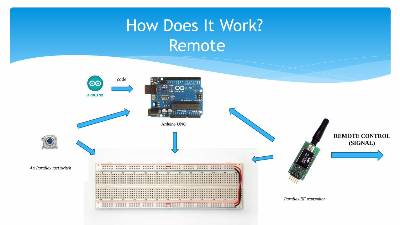
How Does It Work?
Remote
Arduino UNO
code
REMOTE CONTROL
(SIGNAL)
Parallax RF transmitor
4 x Parallax tact switch

How Does It Work?
Car
Boe Bot Chasis1 x parallax standard servo motor
Arduino UNO
codeUltrasonic Sensor
2 x parallax standard continuous servo motor
REMOTE CONTROL
(SIGNAL)
Parallax RF receiver
Arduino UNO
code

How Does It Work?
Remote
Arduino constantly monitors the pushbuttons
Each button is assigned a number i.e. 1, 2 ..
Cyclic Redundancy Check is performed on the input
Data (byte) is sent over RF using the SoftwareSerial library

How Does It Work?Cyclic Redundancy Check:
Used to detect accidental changes to raw data
Simple protection against noise in the transmission channel
A generator polynomial is used in conjunction with the data to perform polynomial long division.
The generator polynomial (x^2 + 1, in this case) is the divisor and the data is the dividend.
Only the remainder is used

How Does It Work?CRC Implementation
Counter – How many individual piece of information (byte)
Data – User input
Save user input in a byte
Pack Counter and Data into a single value (int)
Pad the data with 0’s i.e. shift left by 3 bits
Padded data XOR 101 = Result
Result XOR 0101 (shifted right) until remainder is found

How Does It Work?
Data Transmission
Counter – How many individual piece of information (2 bits)
Data – User input (3 bits)
CRC check value – remainder (3 LSB’s only mask the MSB’s)
Pack all these information in a byte
(Counter << 6) | (Data << 3) | CRC
Send over RF

How Does It Work?Receiver
Unpack the data
Mask out irrelevant bits in each case and then shift i.e.
Counter >> 6, Data >> 3
Calculate CRC value and compare with the received value to verify integrity
Make decision based on the data (i.e. drive pins high or low)

How Does It Work?Boe-bot
It goes on autonomous mode if no data is sent (no buttons are pressed)
During the autonomous mode it will go forward, if it detects an obstacle, it
will check distances in both sides and it will go to side of bigger distance.
Monitor the pins constantly, if any button is pressed, it will change to the
Manual mode
Based on the data received it determines servo angles

3 x Arduino UNO
Ultrasonic Distance Sensor
Parallax Standard Servo Motor
2 x Parallax Continuous Rotation Servo
Parallax RF Transmitter
Parallax RF Receiver
4 x Parallax tact switch
Parallax Boe bot chasis
Piezo Speaker
Components

Arduino UNO
This is the body and the brain of our project. We use
Arduino to receive signals, interpret them and control all
the components in our project.
Arduino is a tool for making smart devices that can sense
and control.
The physical world Arduino is an open-source electronics
prototyping platform based on flexible, easy-to-use
hardware and software.
Arduino microcontroller is programmed using:
Arduino programming language (based on Wiring—C
libraries)
Arduino development environment (based on
Processing), Arduino integrated development
environment (IDE)

Ultrasonic Distance Sensor
The ultrasonic distance sensor provides an easy method of distance measurement. This sensor is perfect for any number of applications that require you to perform measurements between moving or stationary objects.
Interfacing to a microcontroller is a snap. A single I/O pin is used to trigger an ultrasonic burst (well above human hearing) and then "listen" for the echo return pulse. The sensor measures the time required for the echo return, and returns this value to the microcontroller as a variable-width pulse via the same I/O pin.
We have used the ultrasonic distance sensor to detect the objects that avoid us to follow a path. If there is an object in front of the car, the sensor will detect both sides, compare both distances and will go in the direction of the bigger distance.

Parallax Standard Servo Motor
A servo motor is a rotary actuator that allows for precise control of angular position, velocity and acceleration. It consists of a suitable motor coupled to a sensor for position feedback.
The way in which the standard servomotor works in our project is easy. Once the Ultra sonic distance sensor detects that there is an object in front of the car, the servo will rotate to make the ultra sonic distance detector check right and left sides.
This Servo can oscillate from 0 to 180 degrees. And this is all we need, since we don’t have to care about back distances, we only have to turn 90 degrees to check one side, and 180 degrees from there to check the other. This is the reason because we use this servo and not Parallax Continious Rotation.

Parallax Cotinuous Rotation Servo
It has the same characteristics as the Parallax Standard Servo Motor, with the main difference that it can rotate continuosly, whitout 180 degrees limitation.
0 to 50 RPM, with linear response to PWM for easy ramping
In our mini project, the purpose of the Parallax Continuous servos is to move the Boe Bot. To move the car forward, servomotor has to move in different directions, as for moving backward, and to turn one side or the other, one of the servos has to stop turning, and the other will turn max speed, during a short amount of time.

Parallax RF Module (Transmitter & Receiver)
This easy-to-use module is capable of sending and receiving serial data
wirelessly between microcontrollers or to a PC. Low power consumption
makes it ideal for use in battery-powered applications.
Data is sent and received by AM or CPCA modulation, thus offering a
higher average output power which extends the range. This module is
equipped with an RSSI feature that can be utilized to improve power
efficiency by waking up circuitry only when an external signal is
detected and it has a frequency band of 433 MHz.
These transmitter and receiver are the modules that we use to
communicate the Remote control with the Car. The transmitter will
send the signals what we want, the receiver will receive them, and
thanks to Arduino, the signal will be processed and the car will move as
we like.

Parallax tact switch
This tact switch is a normally-open pushbutton
suitable for breadboard or through-hole.
We have used four tact switches to control the manual
mode on out car. Each of the buttons will send a signal
to Arduino on the remote control, and through the RF
Module, the signal will be sent to the car and it will
move the way that we want.

Parallax Piezo-Speaker
Commonly said, it’s as an inexpensive speaker.
In the Manual mode, we have used the Piezo Speaker
imitating the beeping of a car.
In the autonomous mode, the Piezo speaker will beep
when there is an obstacle in front of the car, and it will
beep differently for right and left sides.
For doing that, we should program a code, using
different frequencies for each position, front, right side
and left side.

Parallax Boe bot chasis
This chasis is part of the Parallax Boe Bot Kit and it
has been used to built out car. It comes with two
wheels on the sides, a little ball on the back and a
battery pack that we used to feed Arduino, Ultra
Sonic Sensor and Parallax Standard Servo.
As we will explain in the mechanical design,
Arduino and the servomotors are connected to the
Boe Bot, so we can use the servomotors to move
the wheels and the Arduino to control them
without using difficult and complex wiring.

Car Design
For the mechanical design we have plugged two Arduino UNO and a breadboard into the Boe Bot Kit.
The first Arduino is constantly receiving data from the RF Module and sending the commands to the second Arduino, which controlls the car.
The Parallax Standard Servo in plugged in front of the Boe Bot and the Parallax continuous rotation servos are attached to the wheels.
The Ultrasonic Distance Sensor (used in the autonomous mode) is plugged over the Parallax Standard Servo, which will rotate when an obstacle is in front of the Boe Bot, to make the Ultrasonic Distance Sensor check the distances on the sides.

Remote Design
For the remote we have used a breaboard with four switches and the RF Module Transmitter.
Depending on the switch we press, the car will move in one direction or another

Code
Remote

Code
Remote

Code Receiver

Code Receiver

Code Receiver

Code
Boe Bot

Code
Boe Bot

Code
Boe Bot

Purpose
The main purpose of this first miniproject was to get familiarized with Arduino and its way of programming.
Different components as buttons, Ultrasonic distance sensor, piezo speaker, servos and RF Modules have been used in this Miniproject to have a better understanding of them in Arduino world.
Thanks to this project we have learned how to communicate, how to program and how to use those components with Arduino.

Budget
Name Units Costs
Arduino UNO 3 $44.85
Parallax Standard Servo Motor 1 $12.99
Parallax Continuous Rotation Servo 2 $27.98
Boe Boe Kit 1 $34.99
Parallax tact Switches 4 $2
Ultrasonic Distance Sensor 1 $29.99
RF Module Transmitter and Receiver 1 $24.99
Piezo Speaker 1 $2
Resistors and Batteries Various $10
Approximate Value $189.79

Questions?