advanced natural gas reciprocating engines (ares) · pdf file•not currently applied to...
TRANSCRIPT
Martin L Willi Gas Engines and Alternative Fuels
Global Energy and Technology [email protected] 309-578-8787
U.S. DOE Industrial Distributed Energy Portfolio Review Meeting Washington, D.C.
June 1-2, 2011
Advanced Natural Gas Reciprocating Engines
(ARES)DE-FC26-01CH11079
Caterpillar, Inc.May 2001 – June 2011
The Caterpillar ARES program has developed improvements in power density and fuel consumption that have delivered substantial improvement in owning and operating costs thereby improving the economics of distributed power generation using reciprocating gas engines.
Market impact:•Phase I technologies commercialized in the G3500C/E engines•As of 2009 more than 3.84 gigawatts of ARES technology deployed worldwide•Strong market pull continues
Milestones delivered:•Phase I: 44% efficiency and 0.50 g/hp-hr NOx demonstrated (2004)•Phase II: 47% efficiency and 0.10 g/hp-hr NOx demonstrated (2008)•Phase III: 50% efficiency and 0.10 g/hp-hr NOx technologies under development (demo targeted for 2013)
Executive Summary
Projects and Objectives
System level… Organic Rankine Cycle for heat recovery to power
Problem – efficiency for high hour applications Difficulty – 50% of energy rejected as lower grade heat
Use of alternative fuels – producer gas Problem – need to reduce environmental impact Difficulty – process and feedstock variations
Turbocompound Problem – high value efficiency measure for applications
still requiring waste heat Difficulty – design and integration of turbomachinery and
the effect on the combustion system
Projects and Objectives (cont’d)
Component level… Variable Inlet Valve Actuation
Problem – need to control combustion cylinder to cylinder and cycle to cycle – improve efficiency and response
Difficulty – dynamics of valve train – integration with combustion system
Cylinder Pressure Monitoring Problem – need detailed combustion feedback for control Difficulty – durability at acceptable cost
Laser Ignition Problem – provide energetic, robust, long-life ignition Difficulty – packaging and durability at acceptable cost
Organic Rankine Cycle
Turbine
Pump
Condenser
Evaporator
QW
Q
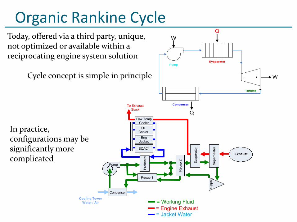
WCycle concept is simple in principle
Today, offered via a third party, unique, not optimized or available within a reciprocating engine system solution
In practice, configurations may be significantly more complicated
To ExhaustStack
Exhaust
Pump
Pre
heat
er
Recup 1
Sup
erhe
ater
Condenser
Turbine
Cooling TowerWater / Air = Working Fluid
= Engine Exhaust
Low TempCooler
OilCooler
Eng JacketWaterSCAC1
Eva
pora
tor
Rec
up 2
= Jacket Water
Organic Rankine Cycle
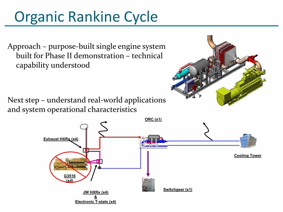
Approach – purpose-built single engine system built for Phase II demonstration – technical capability understood
Next step – understand real-world applications and system operational characteristics
Exhaust HXRs (x4)
ORC (x1)
Switchgear (x1)
G3516 (x4)
JW HXRs (x4)&
Electronic T-stats (x4)
Cooling Tower
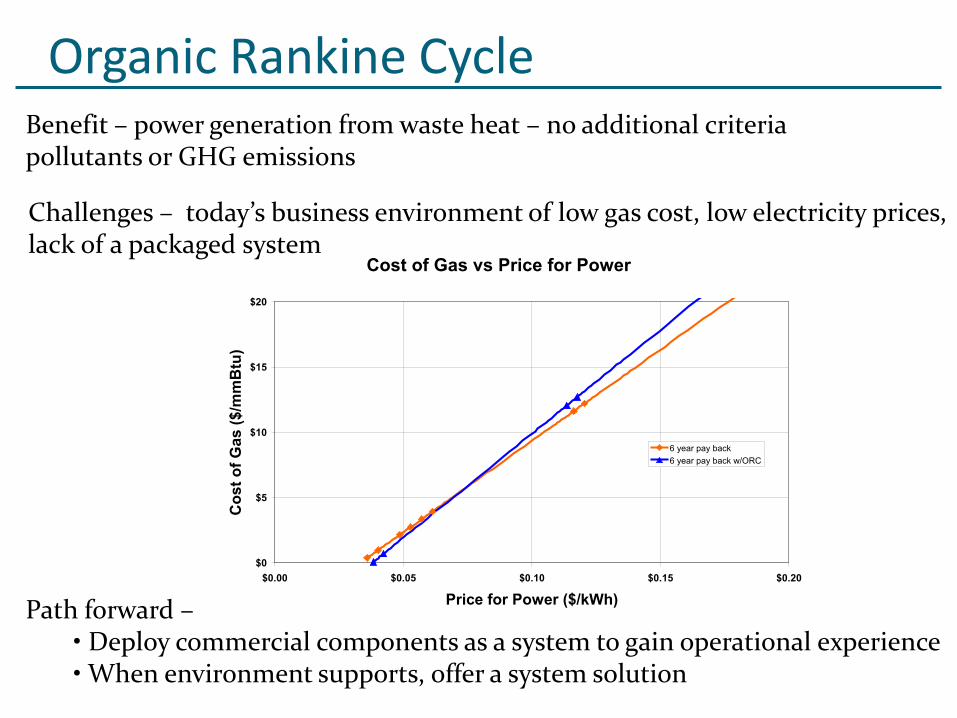
Organic Rankine CycleBenefit – power generation from waste heat – no additional criteria pollutants or GHG emissions
Challenges – today’s business environment of low gas cost, low electricity prices, lack of a packaged system
Path forward –• Deploy commercial components as a system to gain operational experience•When environment supports, offer a system solution
Cost of Gas vs Price for Power
$0
$5
$10
$15
$20
$0.00 $0.05 $0.10 $0.15 $0.20
Price for Power ($/kWh)
Cos
t of G
as ($
/mm
Btu
)
6 year pay back6 year pay back w/ORC
Alternative Fuels – Producer GasConcept
• Provide a system to convert renewable energy feedstocks to low greenhouse gas (GHG) electric power in an ARES-class genset• Define an engine configuration that is flexible over the range of fuels likely to be encountered
Today• Offered with a unique combination of components for each application
• Costly to engineer and deploy
Approach• Engineer a combination of system components that work well together for a variety of feedstocks• Purpose-built engine, generator set combination with appropriate fuel and combustion systems• Deploy first unit and learn what’s required to offer as a “standard” product• Develop fuel characterization tool via work with Colorado State University
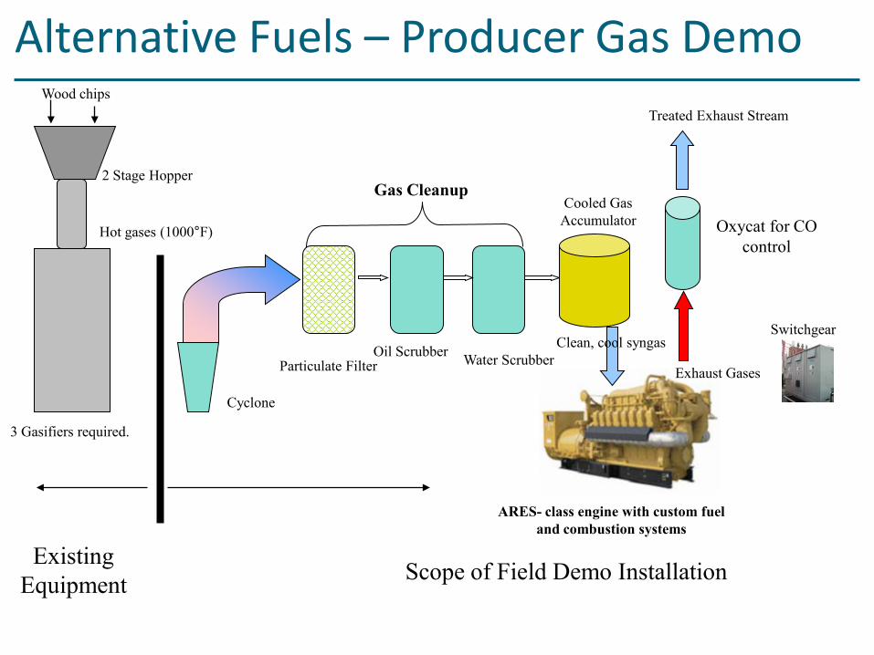
3 Gasifiers required.
Existing Equipment Scope of Field Demo Installation
Gas Cleanup
Cyclone
Wood chips
2 Stage Hopper
Hot gases (1000°F)
ARES- class engine with custom fuel and combustion systems
Cooled Gas Accumulator
Oil Scrubber Water Scrubber
Oxycat for CO control
Exhaust Gases
Clean, cool syngasSwitchgear
Treated Exhaust Stream
Particulate Filter
Alternative Fuels – Producer Gas Demo
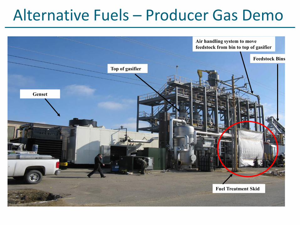
Feedstock Bins
Air handling system to move feedstock from bin to top of gasifier
Fuel Treatment Skid
Top of gasifier
Genset
Alternative Fuels – Producer Gas Demo
Alternative Fuels – Producer Gas
Current status• Engine and gasifier system on-site and under test• Have operated on producer gas for 40 minutes at 50% of targeted load• Next testing will be with genset paralleled to grid • Expect full power demonstration within next two months
Future plans• Operate power system for one year and then transfer ownership to customer• Offer the complete system, gasifier, cleanup, genset, control system as a one stop solution for biomass gasification to electric power
Turbocompound
Concept• Use an additional turbine downstream of the turbocharger turbine to convert exhaust energy to power
Today• Not offered for reciprocating gas engine power generation applications• Used in a few mobile diesel products
Approach• Evaluate impact via single cylinder engine evaluation• Target new high efficiency platform• Concept design to evaluate value proposition• If favorable cost/value, design and procure proof of concept iron –potential Phase III building block
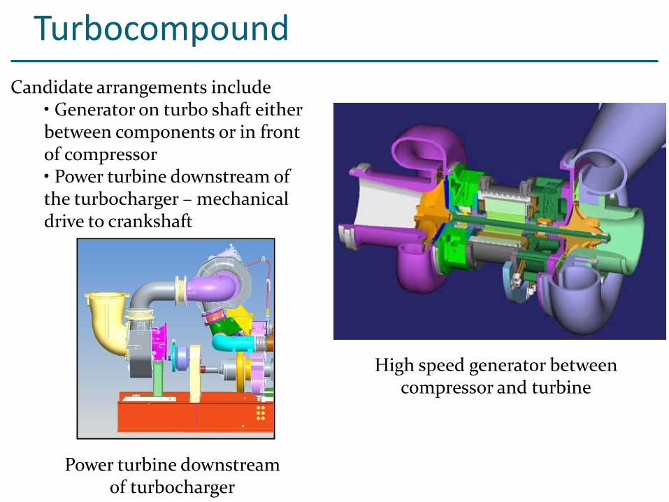
TurbocompoundCandidate arrangements include
• Generator on turbo shaft either between components or in front of compressor• Power turbine downstream of the turbocharger – mechanical drive to crankshaft
High speed generator between compressor and turbine
Power turbine downstream of turbocharger
Turbocompound
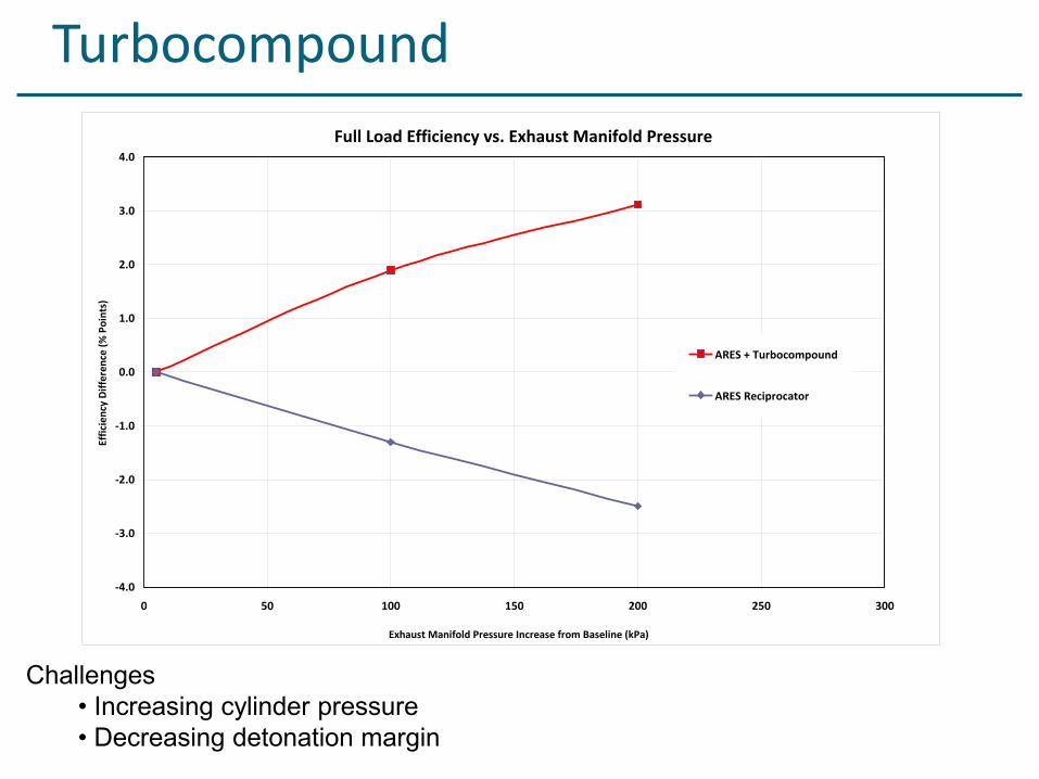
Challenges• Increasing cylinder pressure• Decreasing detonation margin
Full Load Efficiency vs. Exhaust Manifold Pressure
-4.0
-3.0
-2.0
-1.0
0.0
1.0
2.0
3.0
4.0
0 50 100 150 200 250 300
Exhaust Manifold Pressure Increase from Baseline (kPa)
Effic
ienc
y D
iffer
ence
(% P
oint
s)
ARES + Turbocompound
ARES Reciprocator
Current Status Testing on single cylinder test engine indicates potential
benefits Work underway to test concept on new high efficiency
ARES platform
Future Plans Complete concept design based on results from high
efficiency ARES platform tests Evaluate cost/value relationship relative to to other
Phase III technologies If attractive proceed to detailed design and procurement
for multicylinder demonstration
Turbocompound
Variable Inlet Valve Actuation
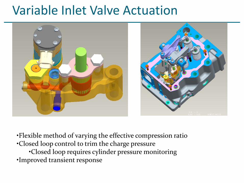
Concept• Use of variable inlet valve timing on a Miller cycle engine allows manipulation of fuel/air charge on a per cycle basis
Today• Offered in some diesel applications for variable compression ratio and compression braking (when applied to exhaust)• Not currently applied to ARES-class reciprocating gas engines
Approach• Design and procure system for single cylinder engine evaluation • Performance test on G3500C/E• Evaluate value proposition relative to other control solutions• If most favorable cost/value, procure proof of concept system for multicylinder engine – potential Phase III building block
Variable Inlet Valve Actuation
•Flexible method of varying the effective compression ratio•Closed loop control to trim the charge pressure
•Closed loop requires cylinder pressure monitoring•Improved transient response
Current Status Testing on single cylinder test engine verifies
performance is as predicted Work underway on alternative method of
cylinder balancing
Future Plans Results of VIVA learning captured,
multicylinder work on hold pending results of alternative method
VIVA work will be taken to multicylinder engine if cost/value analysis supports, relative to other solution
Variable Inlet Valve Actuation
Cylinder Pressure Monitoring
Concept• Cylinder pressure monitoring provides more combustion information than provided today by detonation detection system• Useful for feedback control for per cylinder actuators during “normal” combustion
Today• Complete system is not commercially available for heavy duty engine operation at an attractive cost.• Used in engines much larger than ARES-class engines
Approach• Evaluate sensors from three suppliers• Endurance test the two most attractive options
Cylinder Pressure Monitoring - Sorting
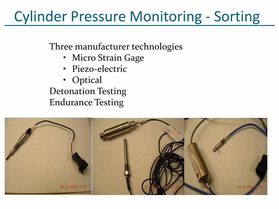
Three manufacturer technologies• Micro Strain Gage • Piezo-electric• Optical
Detonation TestingEndurance Testing
Cylinder Pressure Monitoring
Status - G3520C landfill engine in Massachusetts 20 sensors from two different suppliers Over 9000 hrs per sensor Failure modes identified
Mfr “A” has a manufacturing (batch) issue Mfr “B” has an insulation issue (fix identified)
Heads will be changed in June and sensors collected for retesting against baseline performance
Future plans Summarize post test results Complete the cost/value analysis
Laser IgnitionConcept
• Laser ignition holds promise as a robust, long life ignition source option• Enabler for lean mixture ignition at very high cylinder pressures/loads• Low NOx enabler• Long life and low maintenance attractive as means to extend engine service interval
Today• Not commercially available as a reciprocating engine ignition system
Approach• Team with experts at Colorado State University to identify and remove technology obstacles• Target demonstration on Phase III platform
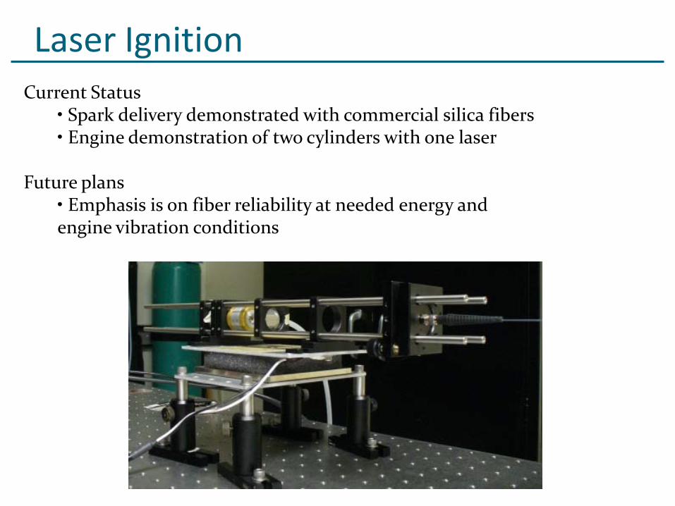
Laser IgnitionCurrent Status
• Spark delivery demonstrated with commercial silica fibers• Engine demonstration of two cylinders with one laser
Future plans• Emphasis is on fiber reliability at needed energy and engine vibration conditions
Phase I technologies successfully deployed beginning in 2004 – demand has validated value
Phase II technologies are on a commercial development path
System and component technology development projects are underway to address efficiency, fuel flexibility, and owning and operating cost
Fuel and electricity pricing will determine the path to lowest owning and operating cost
Summary
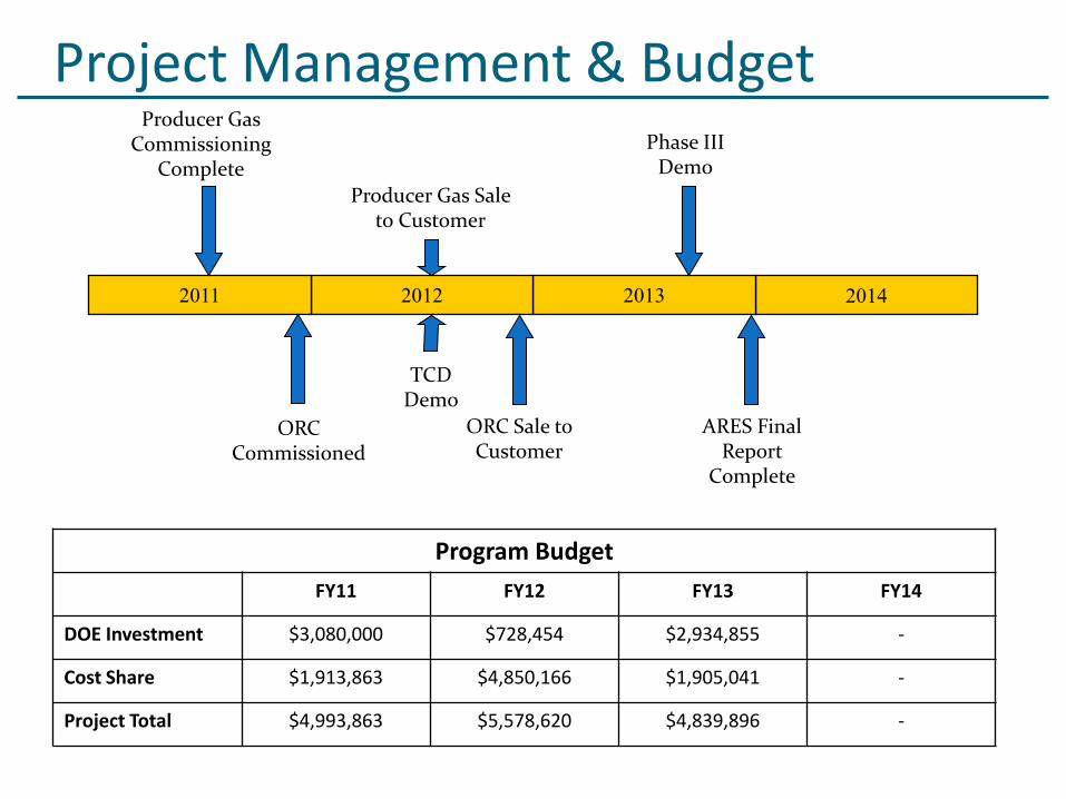
Program BudgetFY11 FY12 FY13 FY14
DOE Investment $3,080,000 $728,454 $2,934,855 -
Cost Share $1,913,863 $4,850,166 $1,905,041 -
Project Total $4,993,863 $5,578,620 $4,839,896 -
Project Management & Budget
2014201320122011
Producer Gas Commissioning
CompleteProducer Gas Sale
to Customer
ORC Commissioned
ORC Sale to Customer
TCD Demo
Phase III Demo
ARES Final Report
Complete
Questions?